communication protocol manual - abb group communication protocol manual describes the communication...
TRANSCRIPT

Relion® Protection and Control
650 seriesIEC 61850 Communication protocol manual

Document ID: 1MRK 511 281-UENIssued: October 2016
Revision: AProduct version: 1.3
© Copyright 2013 ABB. All rights reserved
Copyright
This document and parts thereof must not be reproduced or copied without writtenpermission from ABB, and the contents thereof must not be imparted to a third party,nor used for any unauthorized purpose.
The software and hardware described in this document is furnished under a license andmay be used or disclosed only in accordance with the terms of such license.
This product includes software developed by the OpenSSL Project for use in theOpenSSL Toolkit. (http://www.openssl.org/)
This product includes cryptographic software written/developed by: Eric Young([email protected]) and Tim Hudson ([email protected]).
TrademarksABB and Relion are registered trademarks of the ABB Group. All other brand orproduct names mentioned in this document may be trademarks or registeredtrademarks of their respective holders.
WarrantyPlease inquire about the terms of warranty from your nearest ABB representative.
ABB AB
Grid Automation Products
SE-721 59 Västerås
Sweden
Telephone: +46 (0) 21 32 50 00
Facsimile: +46 (0) 21 14 69 18
http://www.abb.com/protection-control
Disclaimer
The data, examples and diagrams in this manual are included solely for the concept orproduct description and are not to be deemed as a statement of guaranteed properties.All persons responsible for applying the equipment addressed in this manual mustsatisfy themselves that each intended application is suitable and acceptable, includingthat any applicable safety or other operational requirements are complied with. Inparticular, any risks in applications where a system failure and/or product failurewould create a risk for harm to property or persons (including but not limited topersonal injuries or death) shall be the sole responsibility of the person or entityapplying the equipment, and those so responsible are hereby requested to ensure thatall measures are taken to exclude or mitigate such risks.
This document has been carefully checked by ABB but deviations cannot becompletely ruled out. In case any errors are detected, the reader is kindly requested tonotify the manufacturer. Other than under explicit contractual commitments, in noevent shall ABB be responsible or liable for any loss or damage resulting from the useof this manual or the application of the equipment.
Conformity
This product complies with the directive of the Council of the European Communitieson the approximation of the laws of the Member States relating to electromagneticcompatibility (EMC Directive 2004/108/EC) and concerning electrical equipment foruse within specified voltage limits (Low-voltage directive 2006/95/EC). Thisconformity is the result of tests conducted by ABB in accordance with the productstandards EN 50263 and EN 60255-26 for the EMC directive, and with the productstandards EN 60255-1 and EN 60255-27 for the low voltage directive. The product isdesigned in accordance with the international standards of the IEC 60255 series.
Table of contents
Section 1 Introduction.......................................................................7This manual........................................................................................ 7Intended audience.............................................................................. 7Product documentation.......................................................................8
Product documentation set............................................................8Document revision history............................................................. 9Related documents........................................................................9
Symbols and conventions.................................................................11Symbols.......................................................................................11Document conventions................................................................11Functions included in 650 series IEDs........................................ 12
Section 2 Introduction to IEC 61850...............................................17Related documentation to IEC 61850..........................................18
Section 3 Substation Configuration description Language (SCL).. 21The substation section......................................................................22The communication section..............................................................22The IED section................................................................................ 23Tool concept..................................................................................... 26Engineering concept in IEC 61850-6................................................27
Section 4 Communication profile....................................................29
Section 5 Supported services.........................................................31
Section 6 Data sets and control blocks.......................................... 35Data sets.......................................................................................... 35Report control block (URCB/BRCB)................................................. 36GOOSE Control Blocks (GoCB)....................................................... 39
Section 7 Logical node data model................................................ 43Common data objects in each logical node......................................43Logical nodes for automatic control..................................................44
Automatic tap changer control ATCC..........................................44Automatic voltage control for tapchanger, parallel controlTR8ATCC ..............................................................................44Tap changer control and supervision, 6 binary inputsTCMYLTC ............................................................................. 55
Logical nodes for control.................................................................. 58Bay control CBAY........................................................................58
Table of contents
650 series 1Communication protocol manual

Bay control QCBAY................................................................58Logical node for interlocking SCILO ...........................................60Switch controller CSWI................................................................61
Switch controller SCSWI........................................................ 61Logical nodes for conversion functions............................................ 63
Integer to Boolean converter FCVB.............................................63Integer to Boolean 16 conversion with logic noderepresentation IB16FCVB...................................................... 63
Boolean to integer converter FCVI.............................................. 64Boolean 16 to Integer conversion with logic noderepresentation B16IFCVI........................................................64
Logical nodes for protection functions.............................................. 65Differential protection PDIF......................................................... 65
Transformer differential protection, two winding T2WPDIF ...65Transformer differential protection, three windingT3WPDIF ...............................................................................67Restricted earth-fault protection, low impedance REFPDIF ..69Generator differential protection GENPDIF ...........................701Ph High impedance differential protection HZPDIF .............73
Distance protection PDIS............................................................ 74Five zone distance protection, quadrilateral and mhocharacteristic ZQMPDIS.........................................................74Phase selection with load encroachment, quadrilateralcharacteristic FDPSPDIS....................................................... 78Faulty phase identification with load enchroachment formho FMPSPDIS..................................................................... 81Underimpedance protection for generators andtransformers ZGCPDIS.......................................................... 81Loss of excitation LEXPDIS................................................... 84Load enchroachment LEPDIS................................................85
Directional overpower PDOP.......................................................86Directional over-power protection GOPPDOP....................... 86
Directional underpower PDUP.....................................................88Rate of change of frequency PFRC.............................................89
Rate-of-change frequency protection SAPFRC .................... 89Instantaneous overcurrent PIOC.................................................90
Instantaneous phase overcurrent protection 3-phaseoutput PHPIOC ......................................................................90Instantaneous residual overcurrent protection EFPIOC ........91
Local acceleration logic PLAL..................................................... 92Local acceleration logic ZCLCPLAL.......................................92
Protection scheme PSCH............................................................92Scheme communication logic with delta based blockingscheme signal transmit ZCPSCH...........................................92
Table of contents
2 650 seriesCommunication protocol manual

Current reversal and WEI logic for distance protection 3-phase ZCRWPSCH................................................................94Scheme communication logic for residual overcurrentprotection ECPSCH................................................................95Current reversal and weak-end infeed logic for residualovercurrent protection ECRWPSCH...................................... 96
Sensitive directional earth fault PSDE.........................................98Sensitive directional residual overcurrent and powerprotection SDEPSDE ............................................................ 98
Switch onto fault logic PSOF.....................................................100Automatic switch onto fault logic, voltage and currentbased ZCVPSOF .................................................................100
Time over current PTOC........................................................... 100Four step residual overcurrent protection, zero, negativesequence direction EF4PTOC .............................................100Four step phase overcurrent protection 3-phase outputOC4PTOC ........................................................................... 104Four step phase overcurrent protection, phasesegregated output OC4SPTOC............................................107Stub protection STBPTOC .................................................. 111Broken conductor check BRCPTOC ................................... 112Negative sequence based overcurrent function DNSPTOC 112Negative-sequence time overcurrent protection formachines NS2PTOC ........................................................... 115
Overfrequency PTOF................................................................ 117Overfrequency protection SAPTOF .....................................117
Overvoltage PTOV.................................................................... 117Two step overvoltage protection OV2PTOV ....................... 117Two step residual overvoltage protection ROV2PTOV ....... 119
Protection trip conditioning PTRC............................................. 121Tripping logic common 3-phase output SMPPTRC..............121
Thermal overload PTTR............................................................ 123Thermal overload protection, one time constant, CelsiusLCPTTR............................................................................... 123Thermal overload protection, one time constant,Fahrenheit LFPTTR..............................................................124Thermal overload protection, two time constants TRPTTR .126
Time undercurrent PTUC.......................................................... 127Time delayed 2-step undercurrent protection UC2PTUC.....127
Undervoltage PTUV...................................................................130Two step undervoltage protection UV2PTUV ......................130Loss of voltage check LOVPTUV ........................................ 132
Underfrequency PTUF...............................................................133Underfrequency protection SAPTUF ...................................133
Volts per Hz PVPH.................................................................... 134
Table of contents
650 series 3Communication protocol manual
Overexcitation protection OEXPVPH .................................. 134Multipurpose analog protection GAPC...................................... 135
Accidental energizing protection for synchronousgenerator AEGGAPC........................................................... 135
Out-of-step protection PPAM.....................................................136Out-of-step protection OOSPPAM....................................... 136
Earth fault protection PHIZ........................................................ 137100% Stator earth fault protection, 3rd harmonic basedSTEFPHIZ............................................................................ 137
Voltage-restrained time overcurrent PVOC...............................140Voltage-restrained time overcurrent protection VRPVOC.... 140
System logical nodes......................................................................142Physical device information LPHD............................................ 142
Product information PRODINF............................................. 142Logical nodes for protection related functions................................ 142
Breaker failure RBRF................................................................ 142Breaker failure protection 3-phase activation and outputCCRBRF ............................................................................. 142Breaker failure protection phase segregated activationand output CSPRBRF.......................................................... 143
Differential supervision RDIF.....................................................144Current circuit supervision CCSRDIF ..................................144
Disturbance recorder RDRE......................................................145Disturbance report DRPRDRE............................................. 145
Fault locator RFLO.................................................................... 146Fault locator LMBRFLO........................................................146
Fuse failure supervision RFUF..................................................147Fuse failure supervision SDDRFUF..................................... 147
Pole discordance protection RPLD ...........................................147Pole discordance protection CCRPLD ................................ 147
Power swing detection RPSB....................................................148Power swing detection ZMRPSB ........................................ 148
Autoreclosing RREC..................................................................149Autorecloser for 3-phase operation SMBRREC .................. 149Autorecloser for 1/3-phase operation STBRREC ................153
Synchronising RSYN.................................................................156Synchrocheck, energizing check, andsynchronizing SESRSYN..................................................... 156
Logical nodes for generic references............................................. 161Generic process I/O GGIO........................................................ 161
Select Release SELGGIO.................................................... 161Logic rotating switch for function selection and LHMIpresentation SLGGIO...........................................................162Selector mini switch VSGGIO.............................................. 163
Table of contents
4 650 seriesCommunication protocol manual
IEC61850 generic communication I/O functions DPGGIO...165Single point generic control 8 signals SPC8GGIO............... 166Event counter CNTGGIO..................................................... 169Event counter with limit supervision L4UFCNT.................... 170IEC61850 generic communication I/O functions SPGGIO... 172IEC61850 generic communication I/O functions 16 inputsSP16GGIO........................................................................... 173IEC 61850 generic communication I/O functions MVGGIO. 174Pulse-counter logic PCGGIO............................................... 175Trip matrix logic TMAGGIO.................................................. 176Elapsed time integrator with limit transgression andoverflow supervision TEIGGIO.............................................177
Logical nodes for metering and measurement............................... 179Metering MMTR.........................................................................179
Function for energy calculation and demand handlingETPMMTR............................................................................179
Non phase related measurement MMXN.................................. 182Measurements CVMMXN.....................................................182
Measurement MMXU.................................................................186Phase current measurement CMMXU................................. 186Phase-phase voltage measurement VMMXU...................... 187Phase-neutral voltage measurement VNMMXU.................. 189
Sequence and imbalance MSQI................................................191Current sequence component measurement CMSQI.......... 191Voltage sequence measurement VMSQI............................. 193
Logical nodes for sensors and monitoring......................................195Circuit breaker monitoring SCBR.............................................. 195
Breaker close/trip circuit monitoring TCSSCBR................... 195Circuit breaker condition monitoring SSCBR....................... 195
Insulation medium supervision (gas) SIMG...............................200Insulation gas monitoring function SSIMG........................... 200
Insulation medium supervision (liquid) SIML.............................201Insulation liquid monitoring function SSIML......................... 201
Logical nodes for switchgear.......................................................... 203Circuit breaker XCBR................................................................ 203
Circuit breaker SXCBR.........................................................203Switch XSWI..............................................................................205
Circuit switch SXSWI............................................................205Logical nodes for power transformers............................................ 207
Tap changer YLTC.................................................................... 207Tap changer control and supervision, 6 binary inputsTCMYLTC ........................................................................... 207
Logical nodes for further power system equipment........................210Battery ZBAT.............................................................................210
Table of contents
650 series 5Communication protocol manual
Station battery supervision SPVNZBAT............................... 210
Section 8 GOOSE receive blocks................................................ 213Interlock receive - INTLKRCV........................................................ 213
Horizontal communication via GOOSE for interlockingGOOSEINTLKRCV....................................................................213
Binary Receive - BINRCV ..............................................................214Goose binary receive GOOSEBINRCV.....................................214
VCTR Receive - VCTRRCV........................................................... 215Voltage control receiving block for GOOSE GOOSEVCTRRCV215
Double point Receive (DP) - DPRCV ............................................ 216GOOSE function block to receive a double point valueGOOSEDPRCV.........................................................................216
Integer Receive - INTRCV..............................................................217GOOSE function block to receive an integer valueGOOSEINTRCV........................................................................217
Measured Value Receive - MVRCV............................................... 217GOOSE function block to receive a measurand valueGOOSEMVRCV........................................................................ 217
Single Point Receive (SP) - SPRCV...............................................217GOOSE function block to receive a single point valueGOOSESPRCV.........................................................................217
Section 9 Glossary....................................................................... 219
Table of contents
6 650 seriesCommunication protocol manual

Section 1 Introduction
1.1 This manual
The communication protocol manual describes the communication protocolssupported by the IED. The manual concentrates on the vendor-specificimplementations.
1.2 Intended audience
This manual addresses the communication system engineer or system integratorresponsible for pre-engineering and engineering for communication setup in asubstation from an IED perspective.
The system engineer or system integrator must have a basic knowledge ofcommunication in protection and control systems and thorough knowledge of thespecific communication protocol.
1MRK 511 281-UEN A Section 1Introduction
650 series 7Communication protocol manual

1.3 Product documentation
1.3.1 Product documentation set
IEC07000220-3-en.vsd
Pla
nnin
g &
pur
chas
e
Eng
inee
ring
Inst
allin
g
Com
mis
sion
ing
Ope
ratio
n
Mai
nten
ance
Dec
omm
issi
onin
gD
eins
talli
ng &
dis
posa
l
Application manual
Operation manual
Installation manual
Engineering manual
Communication protocol manual
Technical manual
Commissioning manual
IEC07000220 V3 EN
Figure 1: The intended use of manuals throughout the product lifecycle
The engineering manual contains instructions on how to engineer the IEDs using thevarious tools available within the PCM600 software. The manual providesinstructions on how to set up a PCM600 project and insert IEDs to the projectstructure. The manual also recommends a sequence for the engineering of protectionand control functions, LHMI functions as well as communication engineering for IEC60870-5-103, IEC 61850 and DNP 3.0.
The installation manual contains instructions on how to install the IED. The manualprovides procedures for mechanical and electrical installation. The chapters areorganized in the chronological order in which the IED should be installed.
The commissioning manual contains instructions on how to commission the IED. Themanual can also be used by system engineers and maintenance personnel forassistance during the testing phase. The manual provides procedures for the checkingof external circuitry and energizing the IED, parameter setting and configuration aswell as verifying settings by secondary injection. The manual describes the process oftesting an IED in a substation which is not in service. The chapters are organized in the
Section 1 1MRK 511 281-UEN AIntroduction
8 650 seriesCommunication protocol manual
chronological order in which the IED should be commissioned. The relevantprocedures may be followed also during the service and maintenance activities.
The operation manual contains instructions on how to operate the IED once it has beencommissioned. The manual provides instructions for the monitoring, controlling andsetting of the IED. The manual also describes how to identify disturbances and how toview calculated and measured power grid data to determine the cause of a fault.
The application manual contains application descriptions and setting guidelinessorted per function. The manual can be used to find out when and for what purpose atypical protection function can be used. The manual can also provides assistance forcalculating settings.
The technical manual contains application and functionality descriptions and listsfunction blocks, logic diagrams, input and output signals, setting parameters andtechnical data, sorted per function. The manual can be used as a technical referenceduring the engineering phase, installation and commissioning phase, and duringnormal service.
The communication protocol manual describes the communication protocolssupported by the IED. The manual concentrates on the vendor-specificimplementations.
The point list manual describes the outlook and properties of the data points specificto the IED. The manual should be used in conjunction with the correspondingcommunication protocol manual.
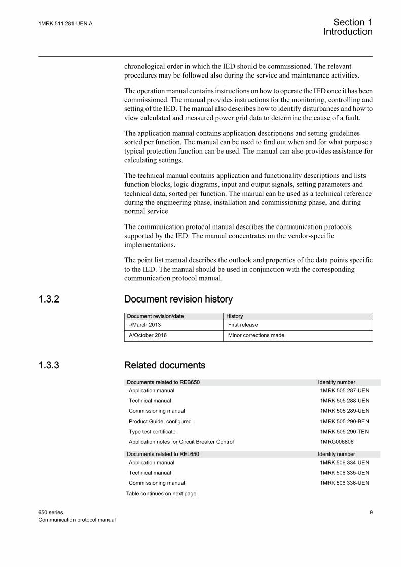
1.3.2 Document revision historyDocument revision/date History-/March 2013 First release
A/October 2016 Minor corrections made
1.3.3 Related documentsDocuments related to REB650 Identity numberApplication manual 1MRK 505 287-UEN
Technical manual 1MRK 505 288-UEN
Commissioning manual 1MRK 505 289-UEN
Product Guide, configured 1MRK 505 290-BEN
Type test certificate 1MRK 505 290-TEN
Application notes for Circuit Breaker Control 1MRG006806
Documents related to REL650 Identity numberApplication manual 1MRK 506 334-UEN
Technical manual 1MRK 506 335-UEN
Commissioning manual 1MRK 506 336-UEN
Table continues on next page
1MRK 511 281-UEN A Section 1Introduction
650 series 9Communication protocol manual

Documents related to REL650 Identity numberProduct Guide 1MRK 506 337-BEN
Type test certificate 1MRK 506 337-TEN
Application notes for Circuit Breaker Control 1MRG006806
Documents related to RET650 Identity numberApplication manual 1MRK 504 134-UEN
Technical manual 1MRK 504 135-UEN
Commissioning manual 1MRK 504 136-UEN
Product Guide, configured 1MRK 504 137-BEN
Type test certificate 1MRK 504 137-TEN
Application notes for Circuit Breaker Control 1MRG006806
Documents related to REC650 Identity numberApplication manual 1MRK 511 286-UEN
Technical manual 1MRK 511 287-UEN
Commissioning manual 1MRK 511 288-UEN
Product Guide 1MRK 511 289-BEN
Type test certificate 1MRK 511 289-TEN
Documents related to REG650 Identity numberApplication manual 1MRK 502 047-UEN
Technical manual 1MRK 502 048-UEN
Commissioning manual 1MRK 502 049-UEN
Product Guide 1MRK 502 050-BEN
Type test certificate 1MRK 502 050-TEN
Rotor Earth Fault Protection with Injection Unit RXTTE4 and REG670 1MRG001910
Application notes for Circuit Breaker Control 1MRG006806
Documents related to REQ650 Identity numberApplication manual 1MRK 505 291-UEN
Technical manual 1MRK 505 292-UEN
Commissioning manual 1MRK 505 293-UEN
Product Guide 1MRK 505 294-BEN
Type test certificate 1MRK 505 294-TEN
Application notes for Circuit Breaker Control 1MRG006806
650 series manuals Identity numberCommunication protocol manual, DNP 3.0 1MRK 511 280-UEN
Communication protocol manual, IEC 61850–8–1 1MRK 511 281-UEN
Communication protocol manual, IEC 60870-5-103 1MRK 511 282-UEN
Cyber Security deployment guidelines 1MRK 511 285-UEN
Point list manual, DNP 3.0 1MRK 511 283-UEN
Engineering manual 1MRK 511 284-UEN
Operation manual 1MRK 500 096-UEN
Installation manual 1MRK 514 016-UEN
Table continues on next page
Section 1 1MRK 511 281-UEN AIntroduction
10 650 seriesCommunication protocol manual

650 series manuals Identity numberAccessories, 650 series 1MRK 513 023-BEN
MICS 1MRG 010 656
PICS 1MRG 010 660
PIXIT 1MRG 010 658
1.4 Symbols and conventions
1.4.1 Symbols
The caution icon indicates important information or warning relatedto the concept discussed in the text. It might indicate the presence ofa hazard which could result in corruption of software or damage toequipment or property.
The information icon alerts the reader of important facts andconditions.
The tip icon indicates advice on, for example, how to design yourproject or how to use a certain function.
Although warning hazards are related to personal injury, it is necessary to understandthat under certain operational conditions, operation of damaged equipment may resultin degraded process performance leading to personal injury or death. It is importantthat the user fully complies with all warning and cautionary notices.
1.4.2 Document conventions
• Abbreviations and acronyms in this manual are spelled out in the glossary. Theglossary also contains definitions of important terms.
• Push button navigation in the LHMI menu structure is presented by using thepush button icons.For example, to navigate between the options, use and .
• HMI menu paths are presented in bold.For example, select Main menu/Settings.
• LHMI messages are shown in Courier font.For example, to save the changes in non-volatile memory, select Yes and press
.• Parameter names are shown in italics.
For example, the function can be enabled and disabled with the Operation setting.• Each function block symbol shows the available input/output signal.
1MRK 511 281-UEN A Section 1Introduction
650 series 11Communication protocol manual
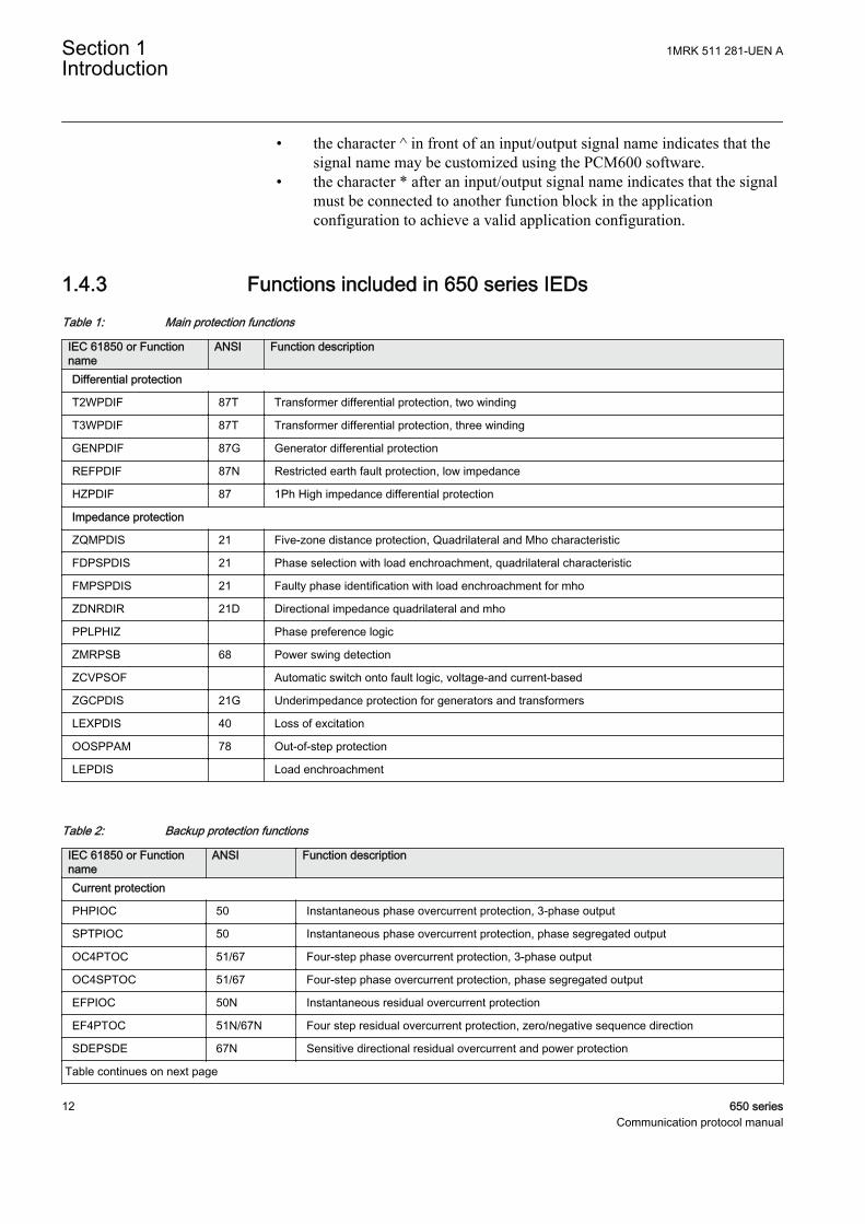
• the character ^ in front of an input/output signal name indicates that thesignal name may be customized using the PCM600 software.
• the character * after an input/output signal name indicates that the signalmust be connected to another function block in the applicationconfiguration to achieve a valid application configuration.
1.4.3 Functions included in 650 series IEDsTable 1: Main protection functions
IEC 61850 or Functionname
ANSI Function description
Differential protection
T2WPDIF 87T Transformer differential protection, two winding
T3WPDIF 87T Transformer differential protection, three winding
GENPDIF 87G Generator differential protection
REFPDIF 87N Restricted earth fault protection, low impedance
HZPDIF 87 1Ph High impedance differential protection
Impedance protection
ZQMPDIS 21 Five-zone distance protection, Quadrilateral and Mho characteristic
FDPSPDIS 21 Phase selection with load enchroachment, quadrilateral characteristic
FMPSPDIS 21 Faulty phase identification with load enchroachment for mho
ZDNRDIR 21D Directional impedance quadrilateral and mho
PPLPHIZ Phase preference logic
ZMRPSB 68 Power swing detection
ZCVPSOF Automatic switch onto fault logic, voltage-and current-based
ZGCPDIS 21G Underimpedance protection for generators and transformers
LEXPDIS 40 Loss of excitation
OOSPPAM 78 Out-of-step protection
LEPDIS Load enchroachment
Table 2: Backup protection functions
IEC 61850 or Functionname
ANSI Function description
Current protection
PHPIOC 50 Instantaneous phase overcurrent protection, 3-phase output
SPTPIOC 50 Instantaneous phase overcurrent protection, phase segregated output
OC4PTOC 51/67 Four-step phase overcurrent protection, 3-phase output
OC4SPTOC 51/67 Four-step phase overcurrent protection, phase segregated output
EFPIOC 50N Instantaneous residual overcurrent protection
EF4PTOC 51N/67N Four step residual overcurrent protection, zero/negative sequence direction
SDEPSDE 67N Sensitive directional residual overcurrent and power protection
Table continues on next page
Section 1 1MRK 511 281-UEN AIntroduction
12 650 seriesCommunication protocol manual
IEC 61850 or Functionname
ANSI Function description
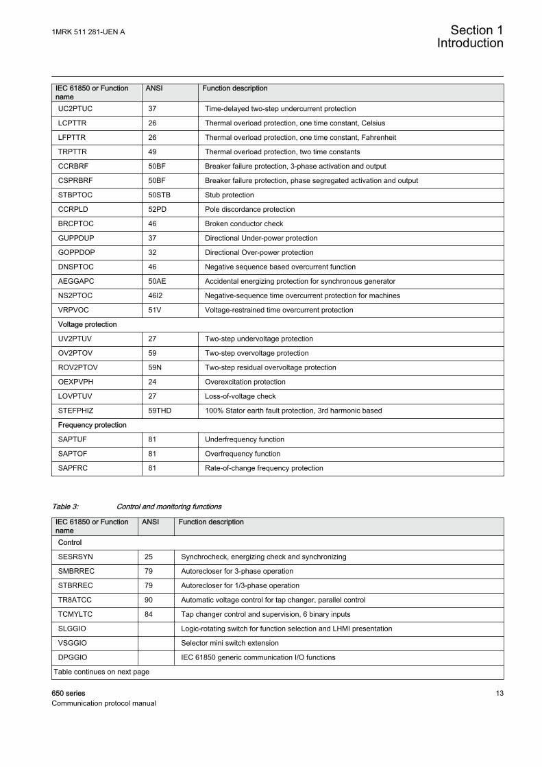
UC2PTUC 37 Time-delayed two-step undercurrent protection
LCPTTR 26 Thermal overload protection, one time constant, Celsius
LFPTTR 26 Thermal overload protection, one time constant, Fahrenheit
TRPTTR 49 Thermal overload protection, two time constants
CCRBRF 50BF Breaker failure protection, 3-phase activation and output
CSPRBRF 50BF Breaker failure protection, phase segregated activation and output
STBPTOC 50STB Stub protection
CCRPLD 52PD Pole discordance protection
BRCPTOC 46 Broken conductor check
GUPPDUP 37 Directional Under-power protection
GOPPDOP 32 Directional Over-power protection
DNSPTOC 46 Negative sequence based overcurrent function
AEGGAPC 50AE Accidental energizing protection for synchronous generator
NS2PTOC 46I2 Negative-sequence time overcurrent protection for machines
VRPVOC 51V Voltage-restrained time overcurrent protection
Voltage protection
UV2PTUV 27 Two-step undervoltage protection
OV2PTOV 59 Two-step overvoltage protection
ROV2PTOV 59N Two-step residual overvoltage protection
OEXPVPH 24 Overexcitation protection
LOVPTUV 27 Loss-of-voltage check
STEFPHIZ 59THD 100% Stator earth fault protection, 3rd harmonic based
Frequency protection
SAPTUF 81 Underfrequency function
SAPTOF 81 Overfrequency function
SAPFRC 81 Rate-of-change frequency protection
Table 3: Control and monitoring functions
IEC 61850 or Functionname
ANSI Function description
Control
SESRSYN 25 Synchrocheck, energizing check and synchronizing
SMBRREC 79 Autorecloser for 3-phase operation
STBRREC 79 Autorecloser for 1/3-phase operation
TR8ATCC 90 Automatic voltage control for tap changer, parallel control
TCMYLTC 84 Tap changer control and supervision, 6 binary inputs
SLGGIO Logic-rotating switch for function selection and LHMI presentation
VSGGIO Selector mini switch extension
DPGGIO IEC 61850 generic communication I/O functions
Table continues on next page
1MRK 511 281-UEN A Section 1Introduction
650 series 13Communication protocol manual
IEC 61850 or Functionname
ANSI Function description
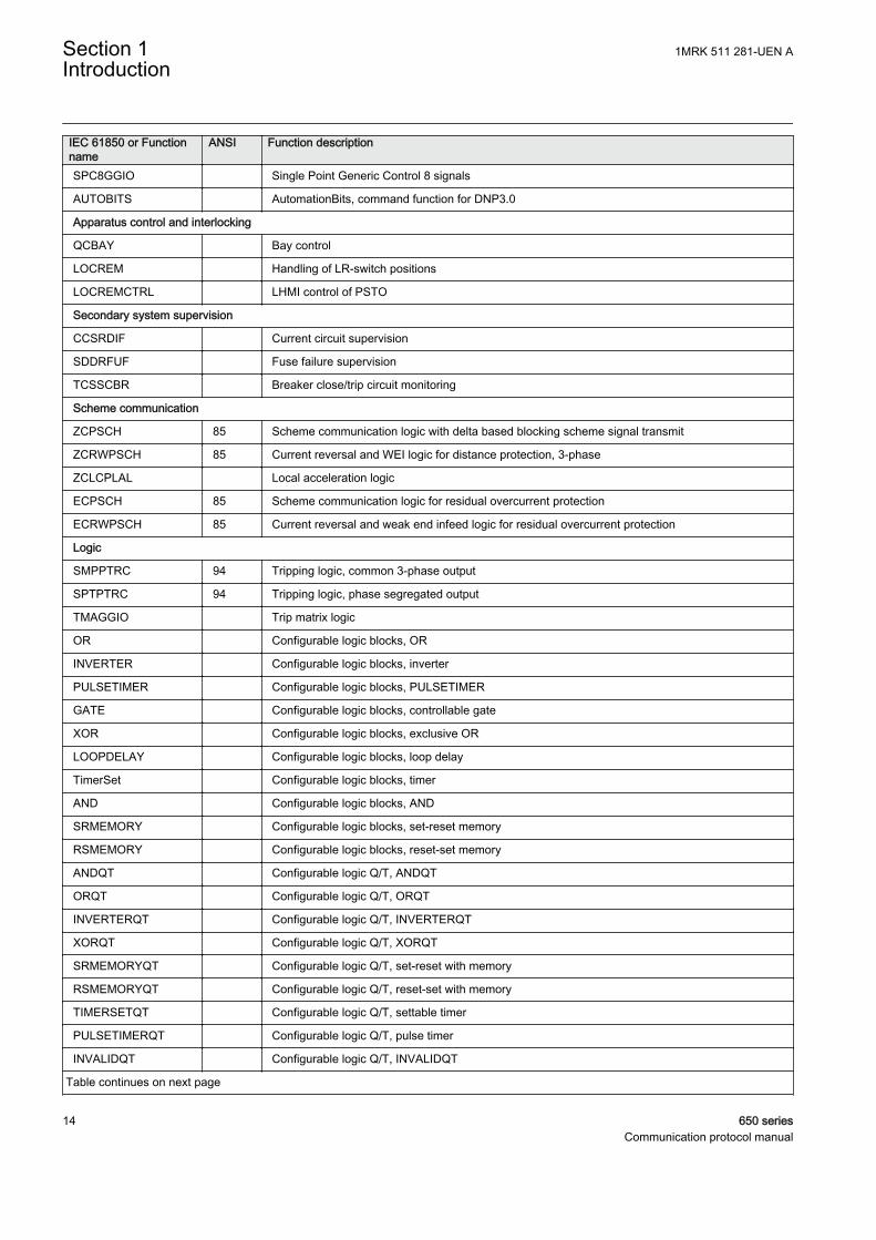
SPC8GGIO Single Point Generic Control 8 signals
AUTOBITS AutomationBits, command function for DNP3.0
Apparatus control and interlocking
QCBAY Bay control
LOCREM Handling of LR-switch positions
LOCREMCTRL LHMI control of PSTO
Secondary system supervision
CCSRDIF Current circuit supervision
SDDRFUF Fuse failure supervision
TCSSCBR Breaker close/trip circuit monitoring
Scheme communication
ZCPSCH 85 Scheme communication logic with delta based blocking scheme signal transmit
ZCRWPSCH 85 Current reversal and WEI logic for distance protection, 3-phase
ZCLCPLAL Local acceleration logic
ECPSCH 85 Scheme communication logic for residual overcurrent protection
ECRWPSCH 85 Current reversal and weak end infeed logic for residual overcurrent protection
Logic
SMPPTRC 94 Tripping logic, common 3-phase output
SPTPTRC 94 Tripping logic, phase segregated output
TMAGGIO Trip matrix logic
OR Configurable logic blocks, OR
INVERTER Configurable logic blocks, inverter
PULSETIMER Configurable logic blocks, PULSETIMER
GATE Configurable logic blocks, controllable gate
XOR Configurable logic blocks, exclusive OR
LOOPDELAY Configurable logic blocks, loop delay
TimerSet Configurable logic blocks, timer
AND Configurable logic blocks, AND
SRMEMORY Configurable logic blocks, set-reset memory
RSMEMORY Configurable logic blocks, reset-set memory
ANDQT Configurable logic Q/T, ANDQT
ORQT Configurable logic Q/T, ORQT
INVERTERQT Configurable logic Q/T, INVERTERQT
XORQT Configurable logic Q/T, XORQT
SRMEMORYQT Configurable logic Q/T, set-reset with memory
RSMEMORYQT Configurable logic Q/T, reset-set with memory
TIMERSETQT Configurable logic Q/T, settable timer
PULSETIMERQT Configurable logic Q/T, pulse timer
INVALIDQT Configurable logic Q/T, INVALIDQT
Table continues on next page
Section 1 1MRK 511 281-UEN AIntroduction
14 650 seriesCommunication protocol manual
IEC 61850 or Functionname
ANSI Function description
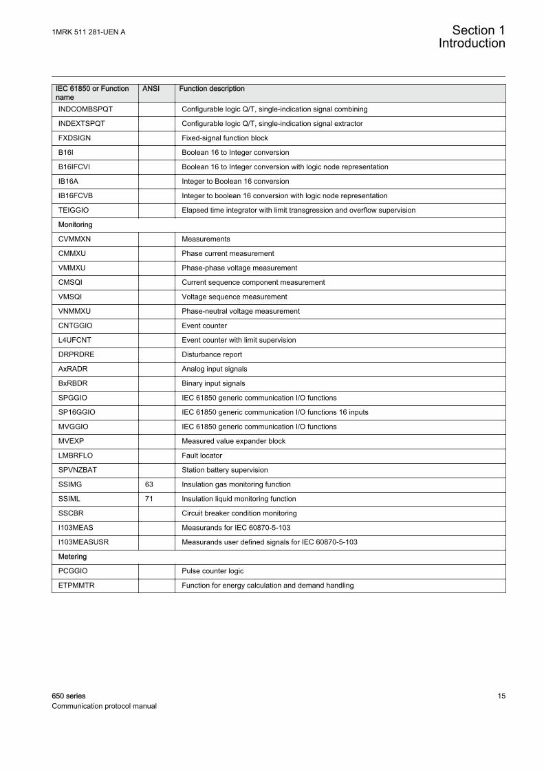
INDCOMBSPQT Configurable logic Q/T, single-indication signal combining
INDEXTSPQT Configurable logic Q/T, single-indication signal extractor
FXDSIGN Fixed-signal function block
B16I Boolean 16 to Integer conversion
B16IFCVI Boolean 16 to Integer conversion with logic node representation
IB16A Integer to Boolean 16 conversion
IB16FCVB Integer to boolean 16 conversion with logic node representation
TEIGGIO Elapsed time integrator with limit transgression and overflow supervision
Monitoring
CVMMXN Measurements
CMMXU Phase current measurement
VMMXU Phase-phase voltage measurement
CMSQI Current sequence component measurement
VMSQI Voltage sequence measurement
VNMMXU Phase-neutral voltage measurement
CNTGGIO Event counter
L4UFCNT Event counter with limit supervision
DRPRDRE Disturbance report
AxRADR Analog input signals
BxRBDR Binary input signals
SPGGIO IEC 61850 generic communication I/O functions
SP16GGIO IEC 61850 generic communication I/O functions 16 inputs
MVGGIO IEC 61850 generic communication I/O functions
MVEXP Measured value expander block
LMBRFLO Fault locator
SPVNZBAT Station battery supervision
SSIMG 63 Insulation gas monitoring function
SSIML 71 Insulation liquid monitoring function
SSCBR Circuit breaker condition monitoring
I103MEAS Measurands for IEC 60870-5-103
I103MEASUSR Measurands user defined signals for IEC 60870-5-103
Metering
PCGGIO Pulse counter logic
ETPMMTR Function for energy calculation and demand handling
1MRK 511 281-UEN A Section 1Introduction
650 series 15Communication protocol manual
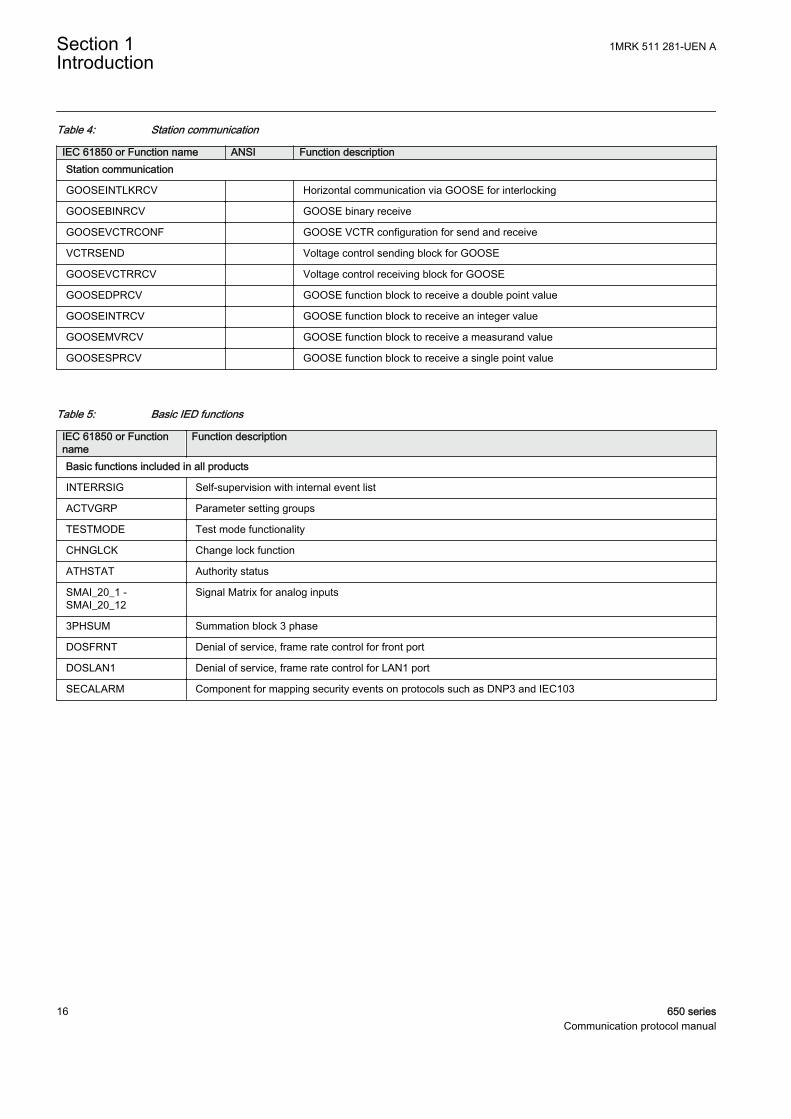
Table 4: Station communication
IEC 61850 or Function name ANSI Function descriptionStation communication
GOOSEINTLKRCV Horizontal communication via GOOSE for interlocking
GOOSEBINRCV GOOSE binary receive
GOOSEVCTRCONF GOOSE VCTR configuration for send and receive
VCTRSEND Voltage control sending block for GOOSE
GOOSEVCTRRCV Voltage control receiving block for GOOSE
GOOSEDPRCV GOOSE function block to receive a double point value
GOOSEINTRCV GOOSE function block to receive an integer value
GOOSEMVRCV GOOSE function block to receive a measurand value
GOOSESPRCV GOOSE function block to receive a single point value
Table 5: Basic IED functions
IEC 61850 or Functionname
Function description
Basic functions included in all products
INTERRSIG Self-supervision with internal event list
ACTVGRP Parameter setting groups
TESTMODE Test mode functionality
CHNGLCK Change lock function
ATHSTAT Authority status
SMAI_20_1 -SMAI_20_12
Signal Matrix for analog inputs
3PHSUM Summation block 3 phase
DOSFRNT Denial of service, frame rate control for front port
DOSLAN1 Denial of service, frame rate control for LAN1 port
SECALARM Component for mapping security events on protocols such as DNP3 and IEC103
Section 1 1MRK 511 281-UEN AIntroduction
16 650 seriesCommunication protocol manual
Section 2 Introduction to IEC 61850
The general scope of the IEC 61850 protocol standard is designed to support thecommunication of all functions being performed in the substation. Its’ main goal isinteroperability; this is the ability for IEDs from one or different manufacturers toexchange information and use the information for their own functions. Moreover, thestandard allows a free allocation of these functions and accepts any systemphilosophy, from a distributed architecture (for example, decentralised substationautomation) to a centralised configuration (for example, RTU based).
The standard separates the functionality represented by the data model and the relatedcommunication services from the communication implementation (stack).
The data model of the standard is an object-oriented one, grouping the data into thesmallest possible sets referring to the smallest possible functions to be implementedindependently. These smallest possible data groups or functions are named logicalnodes. The logical nodes and all data and attributes contained are named according toa standardised semantic, which is mandatory.
This manual describes how the IEC61850 standard is in the 650 series IEDs.References and brief descriptions of the standard are also included. It is assumed thatthe reader has basic knowledge of the IEC 61850 standard.
The following parts of the IEC61850 standard are of importance as they relate to thismanual:
• Station Configuration description Language (SCL) is described in IEC 61850-6.The SCL is an XML based definition of how to describe the parts of a substation.This part of the standard also includes the roles of different tools as well as theengineering concepts.
• Communication profile (IEC 61850 stack) is described in IEC 61850-8-1. Thispart of the standard includes a number of possible communication profiles, andhow the services defined in IEC 61850-7-2 are mapped to the communicationprofile.
• Communication services are described in IEC 61850-7-2. This part deals mainlywith the communication facilities from client and server point of view. It includesthe different possibilities of communication functionality.
• Logical node data model. This is described in IEC 61850-7-3 and IEC61850-7-4.
• Conformance tests and the basis for conformance documents are handled in IEC61850-10.
Detailed information regarding the IEC61850 implementation of the IED 650 isdescribed inside the conformance documents.
1MRK 511 281-UEN A Section 2Introduction to IEC 61850
650 series 17Communication protocol manual
• MICS, Modeling Information Conformance Statement, contains the declarationof the used logical node types.
• PICS, Protocol Information Conformance Statement, contains the details andwhat is supported regarding protocol facilities.
• PIXIT, Protocol Extra Information, contains additional information on how theIEC 61850 is implemented and used.
• TICS, Tissue Information Conformance Statement, contains the supportedTissues, which are handled in the Tissues process as defined by UCA, UtilityCommunication Architecture forum. The Tissues handling is found in http://www.tissue.iec61850.com.
The conformance documents are unique for each product release and refer to eachother; the identities included in the related documents refer to a specific version of the650 series.
The communication profile in IEC 61850 uses the MMS standard, which usesEthernet and TCP/IP to handle the information transport within the substation.
The data modelling uses the concept of logical nodes to identify the publishedinformation for communication. The standard defines a set of logical nodes, eachrepresenting a communication view of a process function with a number of dataobjects. For example, a transformer differential - or line differential protection,because the standard defines only a differential protection. Therefore, it is possible toadapt the logical node, which is defined in the standard, as a logical node class. Thestandard defines methods to describe the actually used logical node as a logical nodetype which is then based upon the logical node class. This allows all partners tointerpret the logical node type information because the description is completelygiven in the standard. The type description of all logical nodes is part of the Data TypeTemplate (DTT) section in the SCL description file of a station or the IED.
Besides the information about the configuration of the communication facilities, thismanual contains the full description of all logical nodes available in the 650 seriesIED. The information about the logical nodes and their data objects may be used toidentify which signals are available for the functions as described in the technicalmanual. The link to the technical manual is done in the logical node tables by listingthe signal name as given in the function block, or as seen in PCM600 or the LHMI.
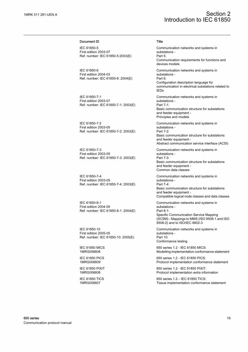
2.1.1 Related documentation to IEC 61850
Use the latest revision of the documents listed, unless stated otherwise.
Section 2 1MRK 511 281-UEN AIntroduction to IEC 61850
18 650 seriesCommunication protocol manual
Document ID Title
IEC 61850-5First edition 2003-07Ref. number: IEC 61850-5:2003(E)
Communication networks and systems insubstations -Part 5:Communication requirements for functions anddevices models
IEC 61850-6First edition 2004-03Ref. number: IEC 61850-6: 2004(E)
Communication networks and systems insubstations -Part 6:Configuration description language forcommunication in electrical substations related toIEDs
IEC 61850-7-1First edition 2003-07Ref. number: IEC 61850-7-1: 2003(E)
Communication networks and systems insubstations -Part 7-1:Basic communication structure for substationsand feeder equipment -Principles and models
IEC 61850-7-2First edition 2003-05Ref. number: IEC 61850-7-2: 2003(E)
Communication networks and systems insubstations -Part 7-2:Basic communication structure for substationsand feeder equipment -Abstract communication service interface (ACSI)
IEC 61850-7-3First edition 2003-05Ref. number: IEC 61850-7-3: 2003(E)
Communication networks and systems insubstations -Part 7-3:Basic communication structure for substationsand feeder equipment -Common data classes
IEC 61850-7-4First edition 2003-05Ref. number: IEC 61850-7-4: 2003(E)
Communication networks and systems insubstations -Part 7-4:Basic communication structure for substationsand feeder equipment -Compatible logical node classes and data classes
IEC 61850-8-1First edition 2004-05Ref. number: IEC 61850-8-1: 2004(E)
Communication networks and systems insubstations -Part 8-1:Specific Communication Service Mapping(SCSM) - Mappings to MMS (ISO 9506-1 and ISO9506-2) and to ISO/IEC 8802-3
IEC 61850-10First edition 2005-05Ref. number: IEC 61850-10: 2005(E)
Communication networks and systems insubstations -Part 10:Conformance testing
IEC 61850 MICS1MRG006606
650 series 1.2 - IEC 61850 MICS:Modelling implementation conformance statement
IEC 61850 PICS1MRG006609
650 series 1.2 - IEC 61850 PICS:Protocol implementation conformance statement
IEC 61850 PIXIT1MRG006608
650 series 1.2 - IEC 61850 PIXIT:Protocol implementation extra information
IEC 61850 TICS1MRG006607
650 series 1.2 – IEC 61850 TICS:Tissue implementation conformance statement
1MRK 511 281-UEN A Section 2Introduction to IEC 61850
650 series 19Communication protocol manual

20

Section 3 Substation Configuration descriptionLanguage (SCL)
Three different types of SCL files - SCD, CID and ICD, can be exported from PCM600.
The SCL language is based on XML. However, detailed knowledge of the XMLcontents is not needed.
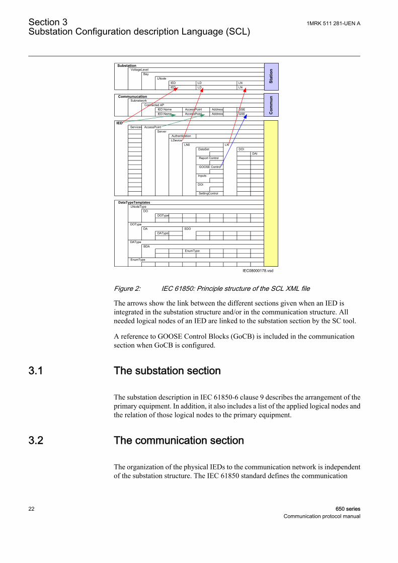
The SCL XML file (ICD/SCD/CID) contains five sections, which are specified in IEC61850–6 clause 9.
• Header• Substation section describes the functional structure and its relation to primary
devices.• Communication section describes the connection between the IED access points
to the respective subnetwork. and includes also the properties (addresses) of theaccess points.
• IED section contains a description of the supported communication services, theaccess point(s) and the IEDs logical devices, logical nodes and their attributes.
• Data type template section contains a declaration of all types used in the SCL file,logical nodes type, DO types, attributes and enums.
The system structure is defined by the organization of the plant structure in PCM600.The signal engineering and the signal routing are IET600 tasks. The IED needs to beconfigured with PCM600 before the system is configured with IET600.
The IED section contains the logical node types included in the respective IEDconfiguration and the data sets and the control blocks configured by IET600. The datasets and the control blocks are logically defined as part of the logical nodes (see IEC61850–7–2 clause 9). IET600 also needs a correctly configured communicationsection for GOOSE engineering.
The data type templates section provides the correct content description of eachlogical node type to all tools and users (clients) of the information. Each IED andvendor may have their own logical node type definitions included in the data typetemplate section together with all other logical node types based on the standard.
1MRK 511 281-UEN A Section 3Substation Configuration description Language (SCL)
650 series 21Communication protocol manual
IEC08000178.vsd
IED Name AccessPoint Address GSEIED Name AccessPoint Address GSE
Services
AuthenticationLDevice
DAI
DOType
DAType
EnumType
SubstationVoltageLevel
BayLNode
IED LD LNIED LD LN
CommunucationSubnetwork
Connected AP
IEDAccessPoint
Server
GOOSE Control
LN0 LNDataSet DOI
DataTypeTemplates
Report Control
Inputs
DOI
SettingControl
LNodeType
DOType
DAType
EnumType
DO
DA
IED
SDO
BDA
Station
Com
mun
IEC08000178 V1 EN
Figure 2: IEC 61850: Principle structure of the SCL XML file
The arrows show the link between the different sections given when an IED isintegrated in the substation structure and/or in the communication structure. Allneeded logical nodes of an IED are linked to the substation section by the SC tool.
A reference to GOOSE Control Blocks (GoCB) is included in the communicationsection when GoCB is configured.
3.1 The substation section
The substation description in IEC 61850-6 clause 9 describes the arrangement of theprimary equipment. In addition, it also includes a list of the applied logical nodes andthe relation of those logical nodes to the primary equipment.
3.2 The communication section
The organization of the physical IEDs to the communication network is independentof the substation structure. The IEC 61850 standard defines the communication
Section 3 1MRK 511 281-UEN ASubstation Configuration description Language (SCL)
22 650 seriesCommunication protocol manual
network with no relation to an existing media or protocol. The mapping to an existingmedia and protocol is specified in IEC 61850–8–1.
The IEC 61850 standard describes in part 7–2 the ACSI in a media and protocolindependent form. Part 8–1 specifies the mapping of this ACSI to the existing MMS.
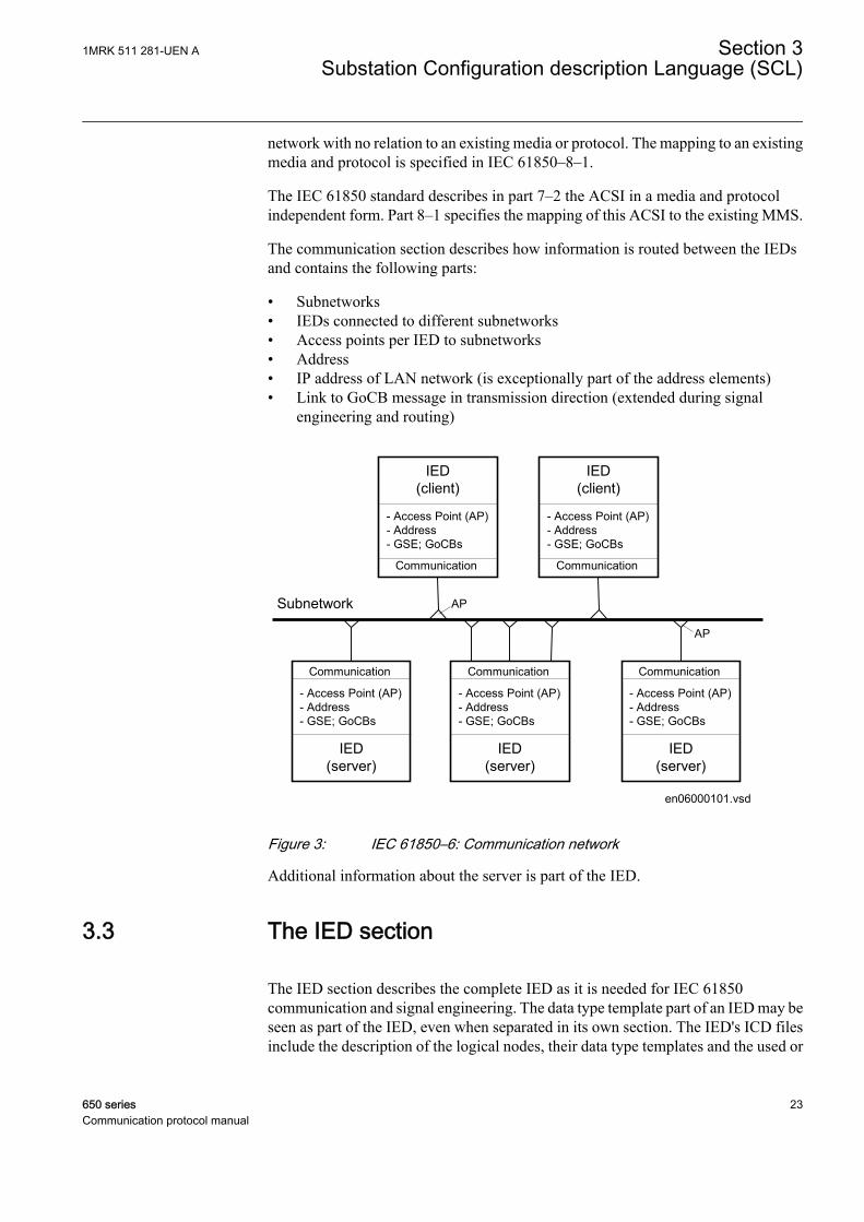
The communication section describes how information is routed between the IEDsand contains the following parts:
• Subnetworks• IEDs connected to different subnetworks• Access points per IED to subnetworks• Address• IP address of LAN network (is exceptionally part of the address elements)• Link to GoCB message in transmission direction (extended during signal
engineering and routing)
en06000101.vsd
IED(server)
- Access Point (AP)- Address- GSE; GoCBs
Communication
AP
IED(server)
- Access Point (AP)- Address- GSE; GoCBs
Communication
IED(server)
- Access Point (AP)- Address- GSE; GoCBs
Communication
AP
IED(client)
- Access Point (AP)- Address- GSE; GoCBs
Communication
IED(client)
- Access Point (AP)- Address- GSE; GoCBs
Communication
Subnetwork
IEC06000101 V1 EN
Figure 3: IEC 61850–6: Communication network
Additional information about the server is part of the IED.
3.3 The IED section
The IED section describes the complete IED as it is needed for IEC 61850communication and signal engineering. The data type template part of an IED may beseen as part of the IED, even when separated in its own section. The IED's ICD filesinclude the description of the logical nodes, their data type templates and the used or
1MRK 511 281-UEN A Section 3Substation Configuration description Language (SCL)
650 series 23Communication protocol manual
supported services. The structure of the IED section follows the definitions made inthe IEC 61850 standard.
Two basic IED types are used in system configuration.
• Station level IEDsare located on the station level and are identified as client IEDs when they read orwrite information from or to the bay IEDs. This functionality is represented bylogical nodes of group “Information (I)”. These are the logical nodes (LN) =ITCI, IHMI and ITMI. Client IEDs are the receiver of information in monitoringdirection and sender of commands (control). These logical nodes have no dataobjects. They are only used to link the report control blocks (BRCBs) from theserver IEDs. They have to read their information about the signals and the signalconfiguration from the bay IEDs. This is possible by checking all control blocksfor a link to it as a client.
• Bay level IEDsare located on the bay level and are identified as server IEDs when they read orwrite information vertically. When GOOSE messages are received, the bay levelIED also has the client role.
Section 3 1MRK 511 281-UEN ASubstation Configuration description Language (SCL)
24 650 seriesCommunication protocol manual

en06000104.vsd
AP
Subnetwork
Control
IED
CVMMXU1
SB1.LD0
Server
LPHD
SXCBR1
SCSWI1
SXSWI1
SCSWI2
SXSWI2
SCSWI3
SXSWI3
SCSWI4
SXSWI4
SCSWI5
LLN0
Mod
CBOpCap
Origin
Data
DataAttribute
Beh
Health
NamePlt
ctlValPos
Loc
OpCnt
BlkOpn
BlkCls
stVal
q
t
LogicalNode
ctlModel
IEC06000104 V2 EN
Figure 4: Organization of LDs, LNs, DOs and DAs in an IED
• A server represents the communication interface to the subnetwork (Ethernet).• One or more logical device(s) (LD) are connected to a server.• A set of logical nodes belong to a LD.• The LN LLN0 is a special logical node per LD and contains for example the data
sets, the various control blocks, inputs (from GOOSE messages). In IED 650series, the data sets and the control blocks shall be located to LD0.
• The LN LPHD is a special logical node per LD and contains data objects thatdescribe the status of the physical device (the IED)
• Each logical node represents a function and contains a number of data objects(DO)
• Each DO includes a number of data attributes (DA)
The data objects represent information signals that may be routed to station level IEDsor to other bay IEDs that are communicating via GOOSE. The signal engineering taskis to select the requested signals (DOs) and link them to the client IEDs as receiver.When using a dataset for MMS, the requested signals are DOs but when creating adataset for GOOSE messaging, DAs are used. The control services are not directly
1MRK 511 281-UEN A Section 3Substation Configuration description Language (SCL)
650 series 25Communication protocol manual
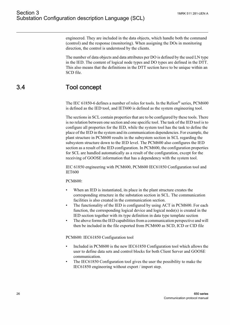
engineered. They are included in the data objects, which handle both the command(control) and the response (monitoring). When assigning the DOs in monitoringdirection, the control is understood by the clients.
The number of data objects and data attributes per DO is defined by the used LN typein the IED. The content of logical node types and DO types are defined in the DTT.This also means that the definitions in the DTT section have to be unique within anSCD file.
3.4 Tool concept
The IEC 61850-6 defines a number of roles for tools. In the Relion® series, PCM600is defined as the IED tool, and IET600 is defined as the system engineering tool.
The sections in SCL contain properties that are to be configured by these tools. Thereis no relation between one section and one specific tool. The task of the IED tool is toconfigure all properties for the IED, while the system tool has the task to define theplace of the IED in the system and its communication dependencies. For example, theplant structure in PCM600 results in the subsystem section in SCL regarding thesubsystem structure down to the IED level. The PCM600 also configures the IEDsection as a result of the IED configuration. In PCM600, the configuration propertiesfor SCL are handled automatically as a result of the configuration, except for thereceiving of GOOSE information that has a dependency with the system tool.
IEC 61850 engineering with PCM600, PCM600 IEC61850 Configuration tool andIET600
PCM600:
• When an IED is instantiated, its place in the plant structure creates thecorresponding structure in the substation section in SCL. The communicationfacilities is also created in the communication section.
• The functionality of the IED is configured by using ACT in PCM600. For eachfunction, the corresponding logical device and logical node(s) is created in theIED section together with its type definition in data type template section
• The above forms the IED capabilities from a communication perspective and willthen be included in the file exported from PCM600 as SCD, ICD or CID file
PCM600: IEC61850 Configuration tool
• Included in PCM600 is the new IEC61850 Configuration tool which allows theuser to define data sets and control blocks for both Client Server and GOOSEcommunication.
• The IEC61850 Configuration tool gives the user the possibility to make theIEC61850 engineering without export / import step.
Section 3 1MRK 511 281-UEN ASubstation Configuration description Language (SCL)
26 650 seriesCommunication protocol manual
It does NOT however allow the User to define the substation part.
IET600:
• Open a SCD file or import/merge a SCD, ICD or CID file for the particularIED(s).
• For each IED, the user defines the datasets, the control blocks for reporting (thismeans unbufffered/buffered reporting and GOOSE) and the properties for eachreport control block.
Data sets (DS) are generated automatically in PCM600. Reportcontrol blocks (RCBs) are not generated automatically inPCM600.
• If client definitions (like client. ICD) are required in the system configuration,they are merged into IET600 and connected to the unbuffered/buffered reportcontrol blocks.
• Logical nodes, which are not related to the conducting equipment, must beincluded in the bay level in the substation section.
• The resulting SCD file is exported from IET600.
PCM600:
Define the inputs for the client in IET600 and cross-reference the signals in SMT.Import the SCD file to PCM600 to receive GOOSE data. For each IED that shallreceive GOOSE information, the received data is connected to the applications usingSMT in PCM600.
If input signals are not defined for clients in IET600, they will not bevisible in SMT.
3.5 Engineering concept in IEC 61850-6
• Top-down approach means that the system engineering tool has ICD filesavailable for each IED to be included in the system configuration. The ICD filesmay be of the template type and represent a pre-configured IED.
• Bottom-up approach means that the configurations are produced by the IED tool,and that are exported as CID files (or SCD file) to be imported into the systemtools.
1MRK 511 281-UEN A Section 3Substation Configuration description Language (SCL)
650 series 27Communication protocol manual

….IED A IED B IED Z
Client A Client B
IEDtool
Systemtool
IEC09000151-1-en.vsd
IEC09000151 V1 EN
Figure 5: Relation between system and IED tools
Regardless of the engineering approach, the idea is that the IED tool provides the CIDor ICD file for each IED. These ICD/CID files are then imported into the system tooland merged into a SCD file, representing the complete substation or a part of thesubstation, like one for each voltage level.
Section 3 1MRK 511 281-UEN ASubstation Configuration description Language (SCL)
28 650 seriesCommunication protocol manual
Section 4 Communication profile
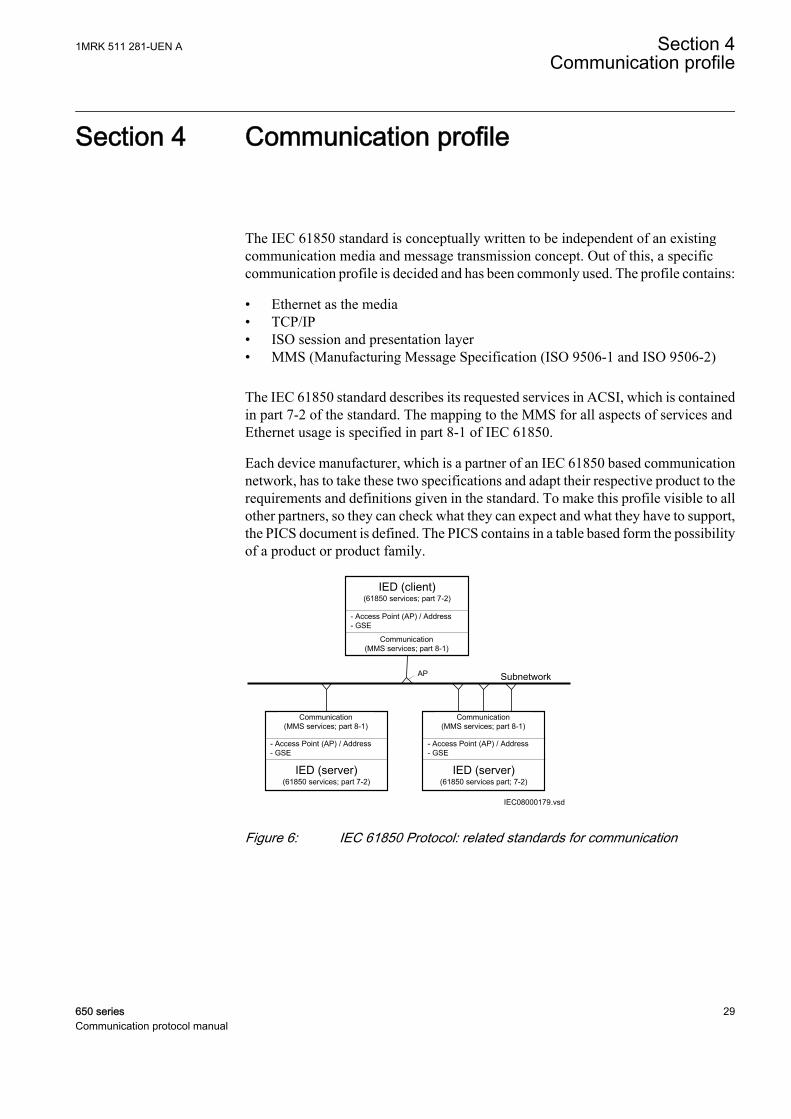
The IEC 61850 standard is conceptually written to be independent of an existingcommunication media and message transmission concept. Out of this, a specificcommunication profile is decided and has been commonly used. The profile contains:
• Ethernet as the media• TCP/IP• ISO session and presentation layer• MMS (Manufacturing Message Specification (ISO 9506-1 and ISO 9506-2)
The IEC 61850 standard describes its requested services in ACSI, which is containedin part 7-2 of the standard. The mapping to the MMS for all aspects of services andEthernet usage is specified in part 8-1 of IEC 61850.
Each device manufacturer, which is a partner of an IEC 61850 based communicationnetwork, has to take these two specifications and adapt their respective product to therequirements and definitions given in the standard. To make this profile visible to allother partners, so they can check what they can expect and what they have to support,the PICS document is defined. The PICS contains in a table based form the possibilityof a product or product family.
IED (server)(61850 services; part 7-2)
Communication(MMS services; part 8-1)
- Access Point (AP) / Address- GSE
IEC08000179.vsd
AP
IED (client)(61850 services; part 7-2)
Subnetwork
IED (server)(61850 services part; 7-2)
Communication(MMS services; part 8-1)
Communication(MMS services; part 8-1)
- Access Point (AP) / Address- GSE
- Access Point (AP) / Address- GSE
IEC08000179 V1 EN
Figure 6: IEC 61850 Protocol: related standards for communication
1MRK 511 281-UEN A Section 4Communication profile
650 series 29Communication protocol manual
SV GOOSE TimeSync(SNTP) MMS Protocol Suite GSSE
TCP/IPT-Profile
ISO COT-Profile
ISO/IEC 8802-2 LLC
GSSET-ProfileUDP/IP
ISO/IEC 8802-3 Ethertype
SampledValues(Multicast)
GenericObjectOrientedSubstationEvent
TimeSync
CoreACSIServices
GenericSubstationStatusEvent
ISO/IEC 8802-3
IEC09000153-1-en.vsd
IEC09000153 V1 EN
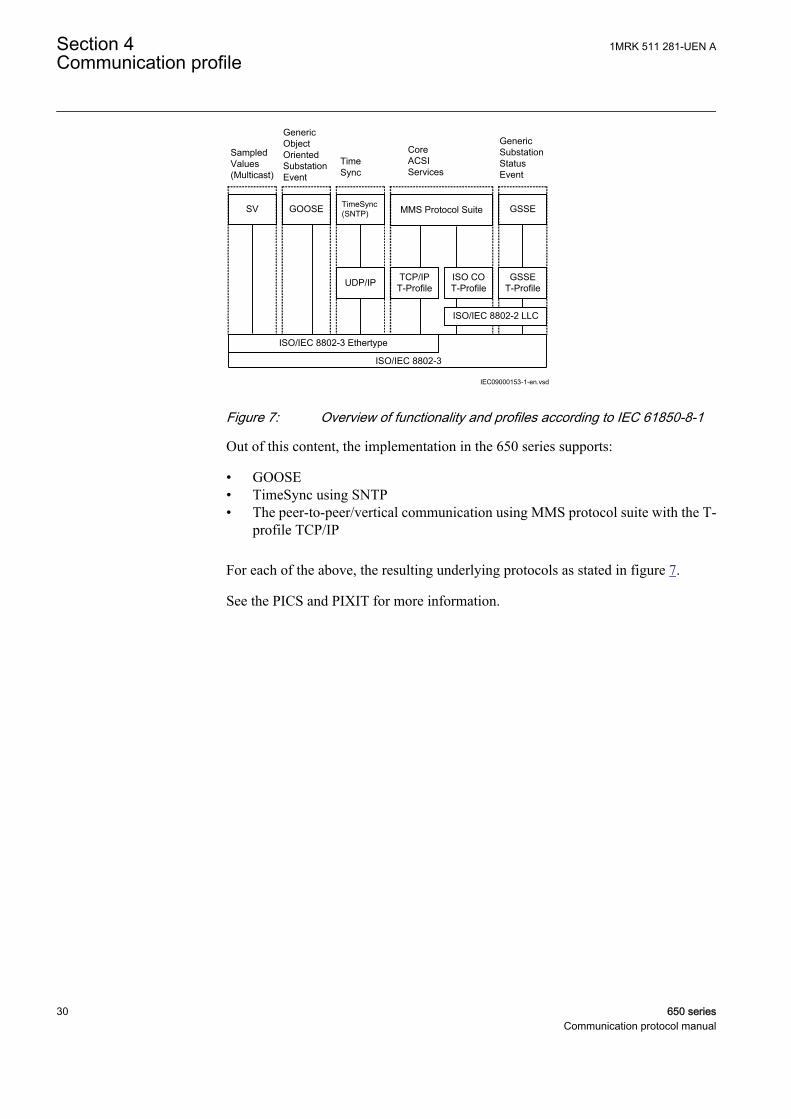
Figure 7: Overview of functionality and profiles according to IEC 61850-8-1
Out of this content, the implementation in the 650 series supports:
• GOOSE• TimeSync using SNTP• The peer-to-peer/vertical communication using MMS protocol suite with the T-
profile TCP/IP
For each of the above, the resulting underlying protocols as stated in figure 7.
See the PICS and PIXIT for more information.
Section 4 1MRK 511 281-UEN ACommunication profile
30 650 seriesCommunication protocol manual
Section 5 Supported services
IEC 61850-7-2 describes the services in the standard. IEC 61850-8-1 describes howthe services are applied in the communication. The conformance documents containthe description of the supported services in the IED.
Services that are not mentioned in this chapter or in the conformance document are notsupported by the IED 650.
Data setDefine data sets by the SCD description.
Create data sets under LD0/LLN0.
The maximum number of data sets (DS) in an IED is 100. Themaximum number of data objects (DO) in a data set for MMS is 100.The maximum data attributes (DA) in a data set for GOOSE is 150.
SubstitutionSubstitution is supported for the respective DATA, according to IEC 61850-7-4, thathave the substitution attributes defined.
Setting group control blockThe task of changing setting groups is supported via the actSG data attribute.
There is only one setting group control block, which is located in LD0/LLN0 (LogicalDevice/Logical Node 0).
Change or edit of setting values as well as reading of setting values is neithersupported nor visible in IEC 61850.
Note that the actual number of used setting groups is defined by theparameter MaxNoSetGRP in the function SETGRPS, which isconfigured in PST in PCM600.
Report control blockFor properties about report control blocks, see PIXIT.
UnBuffered reporting as well as Buffered reporting is supported.
Note that the parameters BufTm and IntPrd shall have the relationBufTm < IntPrd. For best efficiency, the BufTm should have IntPrd as
1MRK 511 281-UEN A Section 5Supported services
650 series 31Communication protocol manual
common denominator, for example: n*BufTm = IntPrd, n is anarbitrary number.
Generic object oriented substation event (GOOSE)The structured GOOSE is supported. This means that the data sets can be defined withFCDA as well as explicit attributes.
The supported data types to be published and received over GOOSE are binary values,double point values, integer values and measured values, together with their quality.One signal is available inside the application to validate the reception of a GOOSEmessage. Invalid means that the correct message is not received within the1.8*maxTime parameter for the GOOSE Control Block (as defined in IEC 61850-6).An incorrect message includes T=true, NeedsCom, wrong order of attributes or anydiscrepancy in the GOOSE message layout.
Note that the data sets that are used or referred to by GOOSE controlblocks can only include a data attribute once. In other words, theremay not be the same data attribute in more than one data set.
When publishing a measured value, the user must take care of which measured valuedata attributes are added to a data set. If the measured value is event-handled (like inthe case of MMXU functions), then one can add that value directly to the data set. Ifthe value is not event-handled, (like in the case of Synchrocheck function), it isrecommended to connect the value desired to be published to a MVGGIO functionblock (in ACT) and then use the measured value given by the MVGGIO.
Example of functions that have event-handled measured values (can be added directlyto the data set).
• CVMMXN - Measurements• CMMXU - Phase current measurement• VMMXU - Phase-phase voltage measurement• CMSQI - Current sequence component measurement• VMSQI - Voltage sequence measurement• VNMMXU - Phase-neutral voltage measurement• MVGGIO - IEC61850 generic communication I/ O functions
Generic function blocks are provided to make available to the 61850 bus signals thatare not defined inside any of the available function blocks. Example of such functionsinclude:
• SPGGIO - IEC61850 generic communication I/ O functions• DPGGIO - IEC61850 generic communication I/ O functions• MVGGIO - IEC61850 generic communication I/ O functions
Section 5 1MRK 511 281-UEN ASupported services
32 650 seriesCommunication protocol manual
ControlOf the different control sequences, the ‘direct-with-normal-security’ and ‘SBO-with-enhanced’ security are supported (defined by the ctlModel parameter, IEC61850-7-2).
Check bits; interlock check and synchrocheck check, are only valid for LN typesbased upon CSWI class.
Verification of Originator Category is supported, see also PIXIT.
1MRK 511 281-UEN A Section 5Supported services
650 series 33Communication protocol manual

34
Section 6 Data sets and control blocks
6.1 Data sets
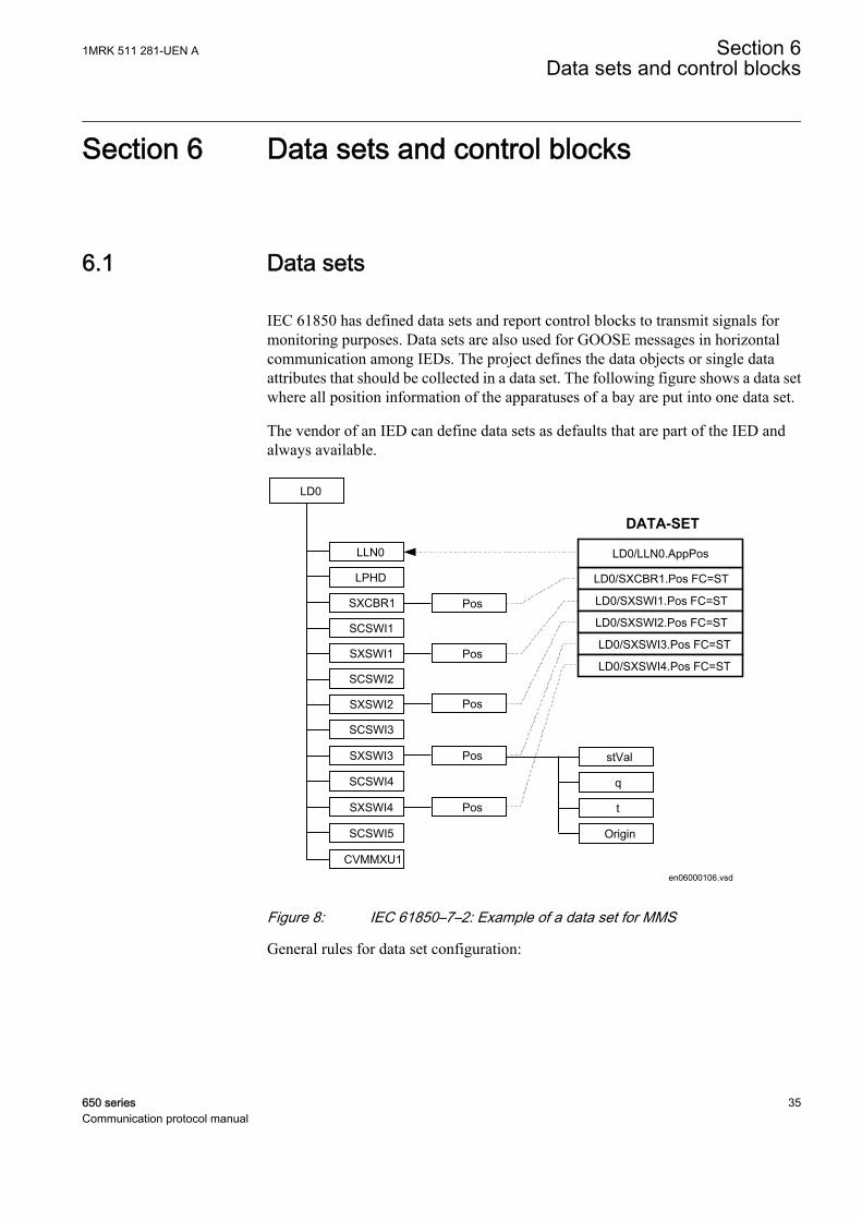
IEC 61850 has defined data sets and report control blocks to transmit signals formonitoring purposes. Data sets are also used for GOOSE messages in horizontalcommunication among IEDs. The project defines the data objects or single dataattributes that should be collected in a data set. The following figure shows a data setwhere all position information of the apparatuses of a bay are put into one data set.
The vendor of an IED can define data sets as defaults that are part of the IED andalways available.
en06000106.vsd
LD0/SXCBR1.Pos FC=ST
LD0/SXSWI1.Pos FC=ST
LD0/SXSWI2.Pos FC=ST
LD0/SXSWI3.Pos FC=ST
LD0/SXSWI4.Pos FC=ST
LD0/LLN0.AppPos
DATA-SET
CVMMXU1
LD0
LPHD
SXCBR1
SCSWI1
SXSWI1
SCSWI2
SXSWI2
SCSWI3
SXSWI3
SCSWI4
SXSWI4
SCSWI5
LLN0
Origin
stVal
q
t
Pos
Pos
Pos
Pos
Pos
IEC06000106 V2 EN
Figure 8: IEC 61850–7–2: Example of a data set for MMS
General rules for data set configuration:
1MRK 511 281-UEN A Section 6Data sets and control blocks
650 series 35Communication protocol manual

• All data objects or their data attributes can be selected for a data set.• Only those data attributes of a data object can/will be selected which have the
same function constraint (FC).• Data objects with different FC can be selected for a data set. For example, DOs
with FC = ST and DOs with FC=MX can be member in one data set.• A single data attribute can be selected when it is specified with a trigger option.
For example, the data attribute stVal of the data object Pos can be selected as amember of a data set, because it is specified with the trigger option data changedetected (dchg).
The description of the data sets with name and the list of data object members (FCDAsis included in the SCL file in the IED section in the Logical device subsection. Asspecified in IEC 61850–7–2 clause 9, the data sets are part of a logical node. They aremost likely included in the LLN0.
6.2 Report control block (URCB/BRCB)
To be able to transmit the signals configured in a DataSet, a report control block mustbe configured to handle and specify how the events are transmitted to the clients.There are two types of report control blocks; unbuffered and buffered. The bufferedreport control block stores the events during a communication interrupt, while theunbuffered is sent upon data change and not stored during interruption.
The content of a BRCB is listed in IEC 61850-7-2 in clause 14. The BRCB containsmany attributes which are of interest to handle and secure the communication betweenthe client and the server and may be set once as default in a project. Others are ofapplication interest in the way events are handled in a project.
• Buffer time (valid only for BRCB)• This parameter describes how long the report should wait for other
expected events before it sends the report to the client. When it is known,that additional events are generated as a follow up, it is useful to wait, forexample, 500 ms for additional events stored in the report. This featurereduces the number of telegrams transmitted in case of a burst of changes.But on the other side it increases the overall transaction time for events fromIED input to presentation on HSI.
• Trigger options• The data attributes know three different trigger options (dchg, qchg, dupd).
Within the BRCB, the two other can be defined (integrity and generalinterrogation). The attribute Trigger option is a multiple choice and allowsto mask the supported trigger options in this BRCB.
• Integrity period• When integrity is selected in the trigger option attribute, it is needed to
define an integrity period to force the transmission of all data listed in theDataSet. This is done by the attribute Integrity period. This feature can beused as a background cycle to ensure that the process image in all partners
Section 6 1MRK 511 281-UEN AData sets and control blocks
36 650 seriesCommunication protocol manual

is the same. The background cycle can repair a lost event in the chain fromthe NCC to an IED.
• General interrogation• A general interrogation is only done on request from a client. Not all Data-
sets may contain information which is needed for a general update of theclient. For example data with T(ransient) = TRUE are not part of a GI.When the BRCB attribute general interrogation is set to TRUE a GI requestfrom the client will be handled. The report handler will transmit all datadefined in the Data-set with their actual values. The IEC 61850 standarddefines that all buffered events shall be transmitted first before the GI isstarted. A running GI shall be stopped and a new GI shall be started, whena new GI request is received while a GI is running.
• Purge buffer (valid only for BRCB)• This BRCB attribute can be used by a client to clean the event buffer from
old events. The events are discarded on request of the client. This featurecan be used to delete old events not transmitted to the client due to stoppedcommunication. After the link is reestablished the client can decide to cleanthe buffer or to receive the history.
Trigger OptionsIEC 61850 has defined in total five different TrgOp. Three of them belonging to dataattributes and marked per data attribute in the column TrgOp of the CDC tables in part7–3. The other two belonging to the configuration of control blocks.
• dchg = data-change• Whenever a process value has changed its value either binary or a
measurement a transmission is done.• qchg = quality change
• Looking to the possibilities of the quality data attribute type (q) any changesin the quality description will be transmitted.
• dupd = data value update• This trigger option give the possibility to define that a transmission should
be done on a condition which can be controlled by the application.• integrity
• This trigger forces the transmission of all process values defined in the dataset when a timer value (the integrity period) expires.
• general interrogation• This trigger is forced by the clients (= station level IED; NCC gateway,
station HMI, ...). Normally a GI is asked for, when the client and the serverstart or restart a session. When the client is able to receive the actual valuesand when the logical device has scanned all process values at least once, animage of the actual process signal status can be transmitted to the client.
1MRK 511 281-UEN A Section 6Data sets and control blocks
650 series 37Communication protocol manual
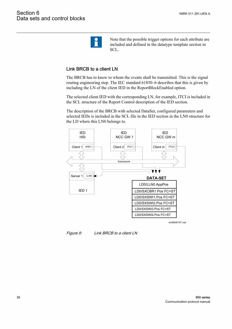
Note that the possible trigger options for each attribute areincluded and defined in the datatype template section inSCL.
Link BRCB to a client LNThe BRCB has to know to whom the events shall be transmitted. This is the signalrouting engineering step. The IEC standard 61850–6 describes that this is given byincluding the LN of the client IED in the ReportBlockEnabled option.
The selected client IED with the corresponding LN, for example, ITCI is included inthe SCL structure of the Report Control description of the IED section.
The description of the BRCB with selected DataSet, configured parameters andselected IEDs is included in the SCL file in the IED section in the LN0 structure forthe LD where this LN0 belongs to.
en06000107.vsd
LD0/SXCBR1.Pos FC=ST
LD0/SXSWI1.Pos FC=ST
LD0/SXSWI2.Pos FC=STLD0/SXSWI3.Pos FC=ST
LD0/SXSWI4.Pos FC=ST
LD0/LLN0.AppPos
DATA-SET
IEDHSI
Client 1
IEDNCC GW 1
Client 2
IEDNCC GW m
Client m
IED 1
Server 1
Subnetwork
ITCI2ITCI1IHSI1
LLN0
IEC06000107 V2 EN
Figure 9: Link BRCB to a client LN
Section 6 1MRK 511 281-UEN AData sets and control blocks
38 650 seriesCommunication protocol manual

6.3 GOOSE Control Blocks (GoCB)
en06000109.vsd
Sen
d
Data-set
Rec
eive
Rec
eive
LN
LN
LNLN
LN
Sen
d
Data-set
Rec
eive
Rec
eive
LNLN
LN LN
Sen
d
Data-set
Rec
eive
Rec
eive
LN
LNLN
LNLN
LN
Subnetwork
LN0
GoCB
DataSet
InputGoCBGoCB
DataSetDataSet
InputInput
Comm.GSE
LD0
Server
LN0
GoCB
DataSet
InputGoCBGoCB
DataSetDataSet
InputInput
Comm.GSE
LD0
Server
IEC06000109 V2 EN
Figure 10: IEC 61850: Principle operation of GOOSE messages
The Generic Object Oriented Substation Event (GOOSE) class model is used todistribute input and output data values between IEDs on bay level (in horizontaldirection) through the use of multicast services. GOOSE messages enable fasttransmission from a publisher to one or several subscribers (receivers).
The GOOSE service model of IEC 61850-7-2 provides the possibility for fast andreliable system-wide distribution of input and output data values. Thisimplementation uses a specific scheme of re-transmission to achieve the appropriatelevel of reliability. When a GOOSE server generates a SendGOOSEMessage request,the current data set values are encoded in a GOOSE message and transmitted on the
1MRK 511 281-UEN A Section 6Data sets and control blocks
650 series 39Communication protocol manual

multicast association. The event that causes the server to invoke a SendGOOSEservice is a local application issue as defined in IEC 61850-7-2. Each update maygenerate a message in order to minimize throughput time.
Additional reliability is achieved by re-transmitting the same data (with graduallyincreasing SqNum and retransmission time).
T0 retransmission in stable conditions (no event for a long time)
(T0) retransmission in stable conditions may be shortened by an event
T1 shortest retransmission time after the event
T2, T3 retransmission times until achieving the stable conditions time
Time of transmission
T0 (T0) T1 T1 T2 T3 T0
eventIEC09000152-1-en.vsd
IEC09000152 V1 EN
Figure 11: Transmission time for events
Each message in the retransmission sequence carries a timeAllowedToLiveparameter that informs the receiver of the maximum time to wait for the next re-transmission. If a new message is not received within that time interval, the receiverassumes that the association is lost. The specific intervals used by any GOOSEpublisher are a local issue. The timeAllowedtoLive parameter informs subscribers ofhow long to wait. In 650 series, the detection time is 1.8*timeAllowedToLive to copewith possible transmission delays.
The GOOSE message concept is used for all application functions where two or moreIEDs are involved. Typical example is the station-wide interlocking procedure orbreaker failure protection.
Figure 10 shows the GOOSE concept for three IEDs which interchange GOOSEmessages between each other.
To send GOOSE messages a GoCB must be defined and a data set is needed thatcontains the data objects of single data attributes to be sent.
A GOOSE message is forced to be transmitted when a trigger change is detected fora data attribute. All members of the data set are copied in the send buffer with their
Section 6 1MRK 511 281-UEN AData sets and control blocks
40 650 seriesCommunication protocol manual
actual value and the message is sent. The subscribers, who knows the address of thisGOOSE message, receives the telegram. The GOOSE message includes a sequencenumber to verify that all messages are received.
1MRK 511 281-UEN A Section 6Data sets and control blocks
650 series 41Communication protocol manual

42
Section 7 Logical node data model
The data model used by IEC 61850 is based on logical nodes containing a set of dataobjects. The data model is defined in the standards.
• IEC 61850-7-4 Compatible logical node classes and data classes• IEC 61850-7-3 Common data classes
The standard describes only classes of logical nodes and data objects on one side andcommon data classes for the data object attributes. Also here it is given has theelements in these classes are defined as:
• Mandatory (M)• Optional (O)• Conditional optional (Cxxx)• In addition, the IEC 61850 states rules for adding vendor-specific definitions to
the standard, in order to cope with extra functionality.
The possible description of the data model according to the standard allows to adapta logical node of a LN class to that what the product is supporting or using for this LN.This definition of what parts of a class is used in the actual product and possibleaddition is called a type, according to IEC 61850-6. There are LN types based uponLN classes. The LN type attributes are called Data Objects (or DATA) and are in ofDO types, base upon respective CDC class. This allows all partners in the IEC 61850project who need this LN to understand the LN in all details for the communicationpart.
The IEC 61850 standard does not describe the functionality and way of operation.Each supplier has to describe this separately. ABB has described their function blocksthat represent a logical node and all other function blocks in the technical manuals.This chapter in the communication protocol manual has two purposes:
• Describe the Logical Node types and their data object attribute types.• Make the link to the description of the function block.
7.1 Common data objects in each logical node
The IEC 61850 standard describes in part 7-5, a Common Logical Node. The dataobjects contained in that LN are both mandatory and optional. The mandatory dataobjects have to be included in each LN. This clause describes the general handling ofthe data objects within the 650 series products.
1MRK 511 281-UEN A Section 7Logical node data model
650 series 43Communication protocol manual
The mandatory data objects as defined in IEC 61850-7-4 as part of the CommonLogical Node are Mode, Behavior, Health and NamePlate.
Mode
The operation modes ON (enabled) and BLOCKED are supported remotely by acommand or locally from the LHMI of the IED. The TEST and the TEST/BLOCKEDmode can be operated locally from the LHMI or by using PCM600.
The state OFF can be set from the LHMI or by using PCM600 for the functions havingthe setting 'operation'.
Note also that for functions in other Logical devices than LD0, the Mod can only becontrolled by communication on LLN0.
Behaviour
The operational mode as given by the Mode control is shown in the data object Behwith the priority rules as described for Beh in clause 6 of IEC 61850-7-4.
The Beh shows the actual state of the function, dependent upon the hierarchydescribed in IEC 61850-7-4, clause 6.
Health
The 650 series products show always only the state "green" = Ok.
NamePlt
The name of the logical node and its relation to namespace definition are shown in thedata object NamePlt as specified for the SCL structure.
7.2 Logical nodes for automatic control
7.2.1 Automatic tap changer control ATCC
7.2.1.1 Automatic voltage control for tapchanger, parallel control TR8ATCC
LN type LN prefix LN class Function block name
TR8ATCC (revision 3) TR8 ATCC TR8ATCC
Section 7 1MRK 511 281-UEN ALogical node data model
44 650 seriesCommunication protocol manual
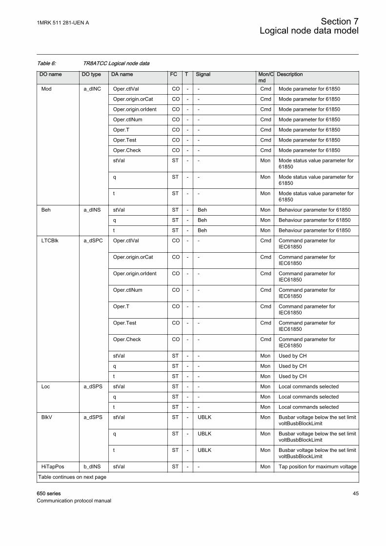
Table 6: TR8ATCC Logical node data
DO name DO type DA name FC T Signal Mon/Cmd
Description
Mod a_dINC Oper.ctlVal CO - - Cmd Mode parameter for 61850
Oper.origin.orCat CO - - Cmd Mode parameter for 61850
Oper.origin.orIdent CO - - Cmd Mode parameter for 61850
Oper.ctlNum CO - - Cmd Mode parameter for 61850
Oper.T CO - - Cmd Mode parameter for 61850
Oper.Test CO - - Cmd Mode parameter for 61850
Oper.Check CO - - Cmd Mode parameter for 61850
stVal ST - - Mon Mode status value parameter for61850
q ST - - Mon Mode status value parameter for61850
t ST - - Mon Mode status value parameter for61850
Beh a_dINS stVal ST - Beh Mon Behaviour parameter for 61850
q ST - Beh Mon Behaviour parameter for 61850
t ST - Beh Mon Behaviour parameter for 61850
LTCBlk a_dSPC Oper.ctlVal CO - - Cmd Command parameter forIEC61850
Oper.origin.orCat CO - - Cmd Command parameter forIEC61850
Oper.origin.orIdent CO - - Cmd Command parameter forIEC61850
Oper.ctlNum CO - - Cmd Command parameter forIEC61850
Oper.T CO - - Cmd Command parameter forIEC61850
Oper.Test CO - - Cmd Command parameter forIEC61850
Oper.Check CO - - Cmd Command parameter forIEC61850
stVal ST - - Mon Used by CH
q ST - - Mon Used by CH
t ST - - Mon Used by CH
Loc a_dSPS stVal ST - - Mon Local commands selected
q ST - - Mon Local commands selected
t ST - - Mon Local commands selected
BlkV a_dSPS stVal ST - UBLK Mon Busbar voltage below the set limitvoltBusbBlockLimit
q ST - UBLK Mon Busbar voltage below the set limitvoltBusbBlockLimit
t ST - UBLK Mon Busbar voltage below the set limitvoltBusbBlockLimit
HiTapPos b_dINS stVal ST - - Mon Tap position for maximum voltage
Table continues on next page
1MRK 511 281-UEN A Section 7Logical node data model
650 series 45Communication protocol manual
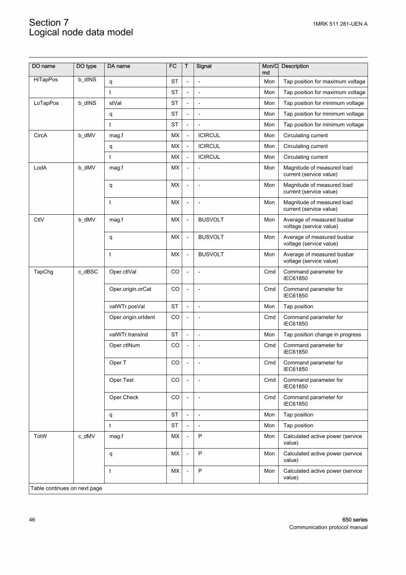
DO name DO type DA name FC T Signal Mon/Cmd
Description
HiTapPos b_dINS q ST - - Mon Tap position for maximum voltage
t ST - - Mon Tap position for maximum voltage
LoTapPos b_dINS stVal ST - - Mon Tap position for minimum voltage
q ST - - Mon Tap position for minimum voltage
t ST - - Mon Tap position for minimum voltage
CircA b_dMV mag.f MX - ICIRCUL Mon Circulating current
q MX - ICIRCUL Mon Circulating current
t MX - ICIRCUL Mon Circulating current
LodA b_dMV mag.f MX - - Mon Magnitude of measured loadcurrent (service value)
q MX - - Mon Magnitude of measured loadcurrent (service value)
t MX - - Mon Magnitude of measured loadcurrent (service value)
CtlV b_dMV mag.f MX - BUSVOLT Mon Average of measured busbarvoltage (service value)
q MX - BUSVOLT Mon Average of measured busbarvoltage (service value)
t MX - BUSVOLT Mon Average of measured busbarvoltage (service value)
TapChg c_dBSC Oper.ctlVal CO - - Cmd Command parameter forIEC61850
Oper.origin.orCat CO - - Cmd Command parameter forIEC61850
valWTr.posVal ST - - Mon Tap position
Oper.origin.orIdent CO - - Cmd Command parameter forIEC61850
valWTr.transInd ST - - Mon Tap position change in progress
Oper.ctlNum CO - - Cmd Command parameter forIEC61850
Oper.T CO - - Cmd Command parameter forIEC61850
Oper.Test CO - - Cmd Command parameter forIEC61850
Oper.Check CO - - Cmd Command parameter forIEC61850
q ST - - Mon Tap position
t ST - - Mon Tap position
TotW c_dMV mag.f MX - P Mon Calculated active power (servicevalue)
q MX - P Mon Calculated active power (servicevalue)
t MX - P Mon Calculated active power (servicevalue)
Table continues on next page
Section 7 1MRK 511 281-UEN ALogical node data model
46 650 seriesCommunication protocol manual
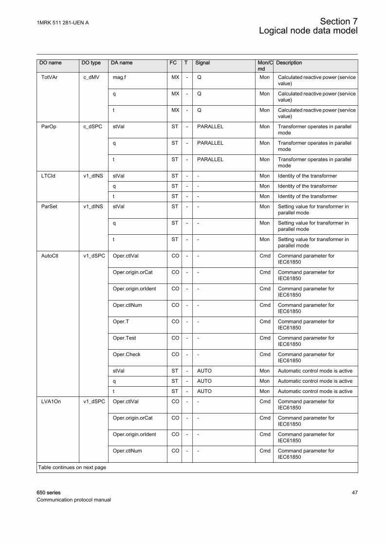
DO name DO type DA name FC T Signal Mon/Cmd
Description
TotVAr c_dMV mag.f MX - Q Mon Calculated reactive power (servicevalue)
q MX - Q Mon Calculated reactive power (servicevalue)
t MX - Q Mon Calculated reactive power (servicevalue)
ParOp c_dSPC stVal ST - PARALLEL Mon Transformer operates in parallelmode
q ST - PARALLEL Mon Transformer operates in parallelmode
t ST - PARALLEL Mon Transformer operates in parallelmode
LTCId v1_dINS stVal ST - - Mon Identity of the transformer
q ST - - Mon Identity of the transformer
t ST - - Mon Identity of the transformer
ParSet v1_dINS stVal ST - - Mon Setting value for transformer inparallel mode
q ST - - Mon Setting value for transformer inparallel mode
t ST - - Mon Setting value for transformer inparallel mode
AutoCtl v1_dSPC Oper.ctlVal CO - - Cmd Command parameter forIEC61850
Oper.origin.orCat CO - - Cmd Command parameter forIEC61850
Oper.origin.orIdent CO - - Cmd Command parameter forIEC61850
Oper.ctlNum CO - - Cmd Command parameter forIEC61850
Oper.T CO - - Cmd Command parameter forIEC61850
Oper.Test CO - - Cmd Command parameter forIEC61850
Oper.Check CO - - Cmd Command parameter forIEC61850
stVal ST - AUTO Mon Automatic control mode is active
q ST - AUTO Mon Automatic control mode is active
t ST - AUTO Mon Automatic control mode is active
LVA1On v1_dSPC Oper.ctlVal CO - - Cmd Command parameter forIEC61850
Oper.origin.orCat CO - - Cmd Command parameter forIEC61850
Oper.origin.orIdent CO - - Cmd Command parameter forIEC61850
Oper.ctlNum CO - - Cmd Command parameter forIEC61850
Table continues on next page
1MRK 511 281-UEN A Section 7Logical node data model
650 series 47Communication protocol manual
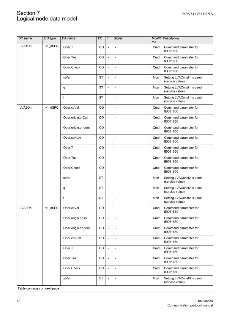
DO name DO type DA name FC T Signal Mon/Cmd
Description
LVA1On v1_dSPC Oper.T CO - - Cmd Command parameter forIEC61850
Oper.Test CO - - Cmd Command parameter forIEC61850
Oper.Check CO - - Cmd Command parameter forIEC61850
stVal ST - - Mon Setting LVAConst1 is used(service value)
q ST - - Mon Setting LVAConst1 is used(service value)
t ST - - Mon Setting LVAConst1 is used(service value)
LVA2On v1_dSPC Oper.ctlVal CO - - Cmd Command parameter forIEC61850
Oper.origin.orCat CO - - Cmd Command parameter forIEC61850
Oper.origin.orIdent CO - - Cmd Command parameter forIEC61850
Oper.ctlNum CO - - Cmd Command parameter forIEC61850
Oper.T CO - - Cmd Command parameter forIEC61850
Oper.Test CO - - Cmd Command parameter forIEC61850
Oper.Check CO - - Cmd Command parameter forIEC61850
stVal ST - - Mon Setting LVAConst2 is used(service value)
q ST - - Mon Setting LVAConst2 is used(service value)
t ST - - Mon Setting LVAConst2 is used(service value)
LVA3On v1_dSPC Oper.ctlVal CO - - Cmd Command parameter forIEC61850
Oper.origin.orCat CO - - Cmd Command parameter forIEC61850
Oper.origin.orIdent CO - - Cmd Command parameter forIEC61850
Oper.ctlNum CO - - Cmd Command parameter forIEC61850
Oper.T CO - - Cmd Command parameter forIEC61850
Oper.Test CO - - Cmd Command parameter forIEC61850
Oper.Check CO - - Cmd Command parameter forIEC61850
stVal ST - - Mon Setting LVAConst3 is used(service value)
Table continues on next page
Section 7 1MRK 511 281-UEN ALogical node data model
48 650 seriesCommunication protocol manual
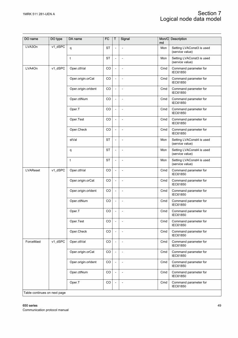
DO name DO type DA name FC T Signal Mon/Cmd
Description
LVA3On v1_dSPC q ST - - Mon Setting LVAConst3 is used(service value)
t ST - - Mon Setting LVAConst3 is used(service value)
LVA4On v1_dSPC Oper.ctlVal CO - - Cmd Command parameter forIEC61850
Oper.origin.orCat CO - - Cmd Command parameter forIEC61850
Oper.origin.orIdent CO - - Cmd Command parameter forIEC61850
Oper.ctlNum CO - - Cmd Command parameter forIEC61850
Oper.T CO - - Cmd Command parameter forIEC61850
Oper.Test CO - - Cmd Command parameter forIEC61850
Oper.Check CO - - Cmd Command parameter forIEC61850
stVal ST - - Mon Setting LVAConst4 is used(service value)
q ST - - Mon Setting LVAConst4 is used(service value)
t ST - - Mon Setting LVAConst4 is used(service value)
LVAReset v1_dSPC Oper.ctlVal CO - - Cmd Command parameter forIEC61850
Oper.origin.orCat CO - - Cmd Command parameter forIEC61850
Oper.origin.orIdent CO - - Cmd Command parameter forIEC61850
Oper.ctlNum CO - - Cmd Command parameter forIEC61850
Oper.T CO - - Cmd Command parameter forIEC61850
Oper.Test CO - - Cmd Command parameter forIEC61850
Oper.Check CO - - Cmd Command parameter forIEC61850
ForceMast v1_dSPC Oper.ctlVal CO - - Cmd Command parameter forIEC61850
Oper.origin.orCat CO - - Cmd Command parameter forIEC61850
Oper.origin.orIdent CO - - Cmd Command parameter forIEC61850
Oper.ctlNum CO - - Cmd Command parameter forIEC61850
Oper.T CO - - Cmd Command parameter forIEC61850
Table continues on next page
1MRK 511 281-UEN A Section 7Logical node data model
650 series 49Communication protocol manual
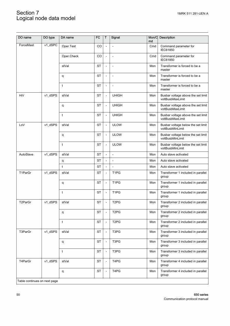
DO name DO type DA name FC T Signal Mon/Cmd
Description
ForceMast v1_dSPC Oper.Test CO - - Cmd Command parameter forIEC61850
Oper.Check CO - - Cmd Command parameter forIEC61850
stVal ST - - Mon Transformer is forced to be amaster
q ST - - Mon Transformer is forced to be amaster
t ST - - Mon Transformer is forced to be amaster
HiV v1_dSPS stVal ST - UHIGH Mon Busbar voltage above the set limitvoltBusbMaxLimit
q ST - UHIGH Mon Busbar voltage above the set limitvoltBusbMaxLimit
t ST - UHIGH Mon Busbar voltage above the set limitvoltBusbMaxLimit
LoV v1_dSPS stVal ST - ULOW Mon Busbar voltage below the set limitvoltBusbMinLimit
q ST - ULOW Mon Busbar voltage below the set limitvoltBusbMinLimit
t ST - ULOW Mon Busbar voltage below the set limitvoltBusbMinLimit
AutoSlave v1_dSPS stVal ST - - Mon Auto slave activated
q ST - - Mon Auto slave activated
t ST - - Mon Auto slave activated
T1ParGr v1_dSPS stVal ST - T1PG Mon Transformer 1 included in parallelgroup
q ST - T1PG Mon Transformer 1 included in parallelgroup
t ST - T1PG Mon Transformer 1 included in parallelgroup
T2ParGr v1_dSPS stVal ST - T2PG Mon Transformer 2 included in parallelgroup
q ST - T2PG Mon Transformer 2 included in parallelgroup
t ST - T2PG Mon Transformer 2 included in parallelgroup
T3ParGr v1_dSPS stVal ST - T3PG Mon Transformer 3 included in parallelgroup
q ST - T3PG Mon Transformer 3 included in parallelgroup
t ST - T3PG Mon Transformer 3 included in parallelgroup
T4ParGr v1_dSPS stVal ST - T4PG Mon Transformer 4 included in parallelgroup
q ST - T4PG Mon Transformer 4 included in parallelgroup
Table continues on next page
Section 7 1MRK 511 281-UEN ALogical node data model
50 650 seriesCommunication protocol manual
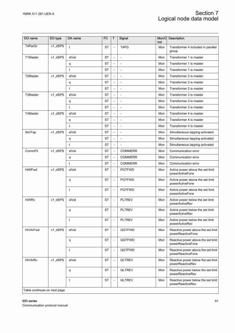
DO name DO type DA name FC T Signal Mon/Cmd
Description
T4ParGr v1_dSPS t ST - T4PG Mon Transformer 4 included in parallelgroup
T1Master v1_dSPS stVal ST - - Mon Transformer 1 is master
q ST - - Mon Transformer 1 is master
t ST - - Mon Transformer 1 is master
T2Master v1_dSPS stVal ST - - Mon Transformer 2 is master
q ST - - Mon Transformer 2 is master
t ST - - Mon Transformer 2 is master
T3Master v1_dSPS stVal ST - - Mon Transformer 3 is master
q ST - - Mon Transformer 3 is master
t ST - - Mon Transformer 3 is master
T4Master v1_dSPS stVal ST - - Mon Transformer 4 is master
q ST - - Mon Transformer 4 is master
t ST - - Mon Transformer 4 is master
SimTap v1_dSPS stVal ST - - Mon Simultaneous tapping activated
q ST - - Mon Simultaneous tapping activated
t ST - - Mon Simultaneous tapping activated
CommFlt v1_dSPS stVal ST - COMMERR Mon Communication error
q ST - COMMERR Mon Communication error
t ST - COMMERR Mon Communication error
HiWFwd v1_dSPS stVal ST - PGTFWD Mon Active power above the set limitpowerActiveForw
q ST - PGTFWD Mon Active power above the set limitpowerActiveForw
t ST - PGTFWD Mon Active power above the set limitpowerActiveForw
HiWRv v1_dSPS stVal ST - PLTREV Mon Active power below the set limitpowerActiveRev
q ST - PLTREV Mon Active power below the set limitpowerActiveRev
t ST - PLTREV Mon Active power below the set limitpowerActiveRev
HiVArFwd v1_dSPS stVal ST - QGTFWD Mon Reactive power above the set limitpowerReactiveForw
q ST - QGTFWD Mon Reactive power above the set limitpowerReactiveForw
t ST - QGTFWD Mon Reactive power above the set limitpowerReactiveForw
HiVArRv v1_dSPS stVal ST - QLTREV Mon Reactive power below the set limitpowerReactiveRev
q ST - QLTREV Mon Reactive power below the set limitpowerReactiveRev
t ST - QLTREV Mon Reactive power below the set limitpowerReactiveRev
Table continues on next page
1MRK 511 281-UEN A Section 7Logical node data model
650 series 51Communication protocol manual
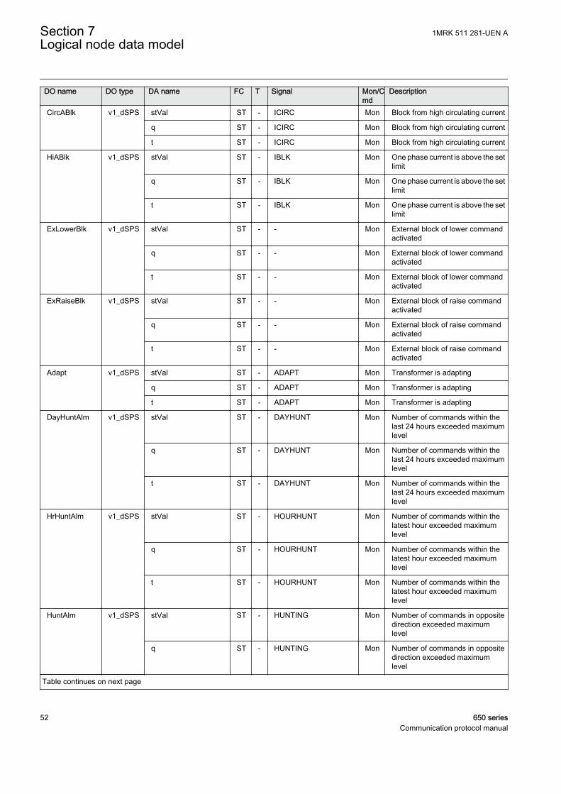
DO name DO type DA name FC T Signal Mon/Cmd
Description
CircABlk v1_dSPS stVal ST - ICIRC Mon Block from high circulating current
q ST - ICIRC Mon Block from high circulating current
t ST - ICIRC Mon Block from high circulating current
HiABlk v1_dSPS stVal ST - IBLK Mon One phase current is above the setlimit
q ST - IBLK Mon One phase current is above the setlimit
t ST - IBLK Mon One phase current is above the setlimit
ExLowerBlk v1_dSPS stVal ST - - Mon External block of lower commandactivated
q ST - - Mon External block of lower commandactivated
t ST - - Mon External block of lower commandactivated
ExRaiseBlk v1_dSPS stVal ST - - Mon External block of raise commandactivated
q ST - - Mon External block of raise commandactivated
t ST - - Mon External block of raise commandactivated
Adapt v1_dSPS stVal ST - ADAPT Mon Transformer is adapting
q ST - ADAPT Mon Transformer is adapting
t ST - ADAPT Mon Transformer is adapting
DayHuntAlm v1_dSPS stVal ST - DAYHUNT Mon Number of commands within thelast 24 hours exceeded maximumlevel
q ST - DAYHUNT Mon Number of commands within thelast 24 hours exceeded maximumlevel
t ST - DAYHUNT Mon Number of commands within thelast 24 hours exceeded maximumlevel
HrHuntAlm v1_dSPS stVal ST - HOURHUNT Mon Number of commands within thelatest hour exceeded maximumlevel
q ST - HOURHUNT Mon Number of commands within thelatest hour exceeded maximumlevel
t ST - HOURHUNT Mon Number of commands within thelatest hour exceeded maximumlevel
HuntAlm v1_dSPS stVal ST - HUNTING Mon Number of commands in oppositedirection exceeded maximumlevel
q ST - HUNTING Mon Number of commands in oppositedirection exceeded maximumlevel
Table continues on next page
Section 7 1MRK 511 281-UEN ALogical node data model
52 650 seriesCommunication protocol manual
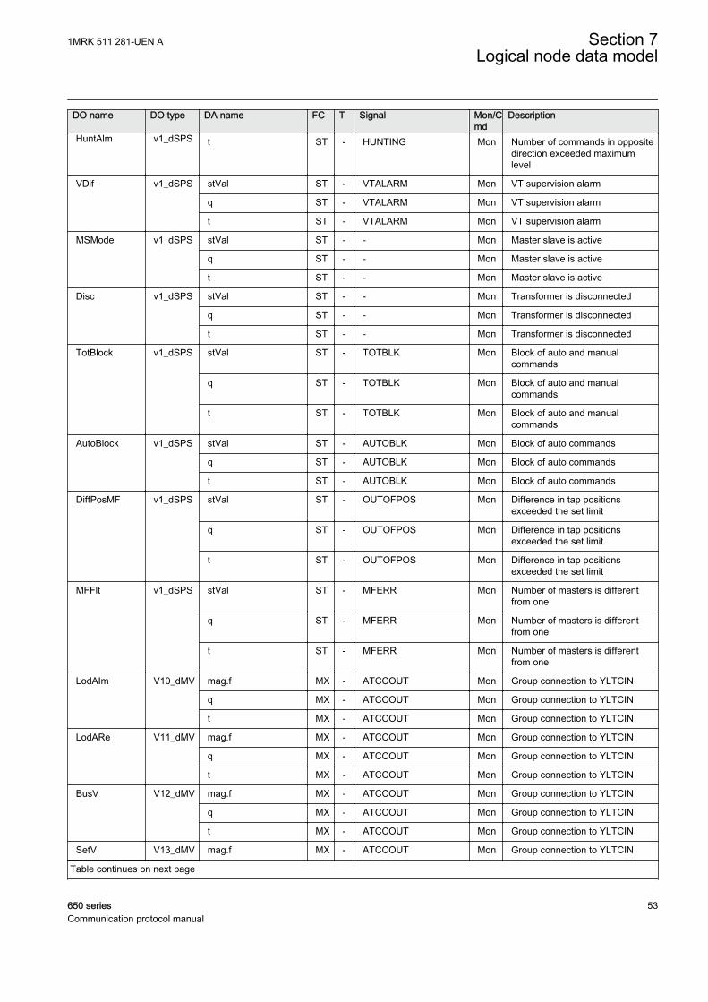
DO name DO type DA name FC T Signal Mon/Cmd
Description
HuntAlm v1_dSPS t ST - HUNTING Mon Number of commands in oppositedirection exceeded maximumlevel
VDif v1_dSPS stVal ST - VTALARM Mon VT supervision alarm
q ST - VTALARM Mon VT supervision alarm
t ST - VTALARM Mon VT supervision alarm
MSMode v1_dSPS stVal ST - - Mon Master slave is active
q ST - - Mon Master slave is active
t ST - - Mon Master slave is active
Disc v1_dSPS stVal ST - - Mon Transformer is disconnected
q ST - - Mon Transformer is disconnected
t ST - - Mon Transformer is disconnected
TotBlock v1_dSPS stVal ST - TOTBLK Mon Block of auto and manualcommands
q ST - TOTBLK Mon Block of auto and manualcommands
t ST - TOTBLK Mon Block of auto and manualcommands
AutoBlock v1_dSPS stVal ST - AUTOBLK Mon Block of auto commands
q ST - AUTOBLK Mon Block of auto commands
t ST - AUTOBLK Mon Block of auto commands
DiffPosMF v1_dSPS stVal ST - OUTOFPOS Mon Difference in tap positionsexceeded the set limit
q ST - OUTOFPOS Mon Difference in tap positionsexceeded the set limit
t ST - OUTOFPOS Mon Difference in tap positionsexceeded the set limit
MFFlt v1_dSPS stVal ST - MFERR Mon Number of masters is differentfrom one
q ST - MFERR Mon Number of masters is differentfrom one
t ST - MFERR Mon Number of masters is differentfrom one
LodAIm V10_dMV mag.f MX - ATCCOUT Mon Group connection to YLTCIN
q MX - ATCCOUT Mon Group connection to YLTCIN
t MX - ATCCOUT Mon Group connection to YLTCIN
LodARe V11_dMV mag.f MX - ATCCOUT Mon Group connection to YLTCIN
q MX - ATCCOUT Mon Group connection to YLTCIN
t MX - ATCCOUT Mon Group connection to YLTCIN
BusV V12_dMV mag.f MX - ATCCOUT Mon Group connection to YLTCIN
q MX - ATCCOUT Mon Group connection to YLTCIN
t MX - ATCCOUT Mon Group connection to YLTCIN
SetV V13_dMV mag.f MX - ATCCOUT Mon Group connection to YLTCIN
Table continues on next page
1MRK 511 281-UEN A Section 7Logical node data model
650 series 53Communication protocol manual

DO name DO type DA name FC T Signal Mon/Cmd
Description
SetV V13_dMV q MX - ATCCOUT Mon Group connection to YLTCIN
t MX - ATCCOUT Mon Group connection to YLTCIN
PosRel V14_dMV mag.f MX - ATCCOUT Mon Group connection to YLTCIN
q MX - ATCCOUT Mon Group connection to YLTCIN
t MX - ATCCOUT Mon Group connection to YLTCIN
X2 V15_dMV mag.f MX - ATCCOUT Mon Group connection to YLTCIN
q MX - ATCCOUT Mon Group connection to YLTCIN
t MX - ATCCOUT Mon Group connection to YLTCIN
BndCtrAct v2_dMV mag.f MX - - Mon Actual voltage setpoint
q MX - - Mon Actual voltage setpoint
t MX - - Mon Actual voltage setpoint
LodV v2_dMV mag.f MX - ULOAD Mon Calculated compensated voltage(service value)
q MX - ULOAD Mon Calculated compensated voltage(service value)
t MX - ULOAD Mon Calculated compensated voltage(service value)
AverA v2_dMV mag.f MX - IPRIM Mon Maximum of 3 phase currents(service value)
q MX - IPRIM Mon Maximum of 3 phase currents(service value)
t MX - IPRIM Mon Maximum of 3 phase currents(service value)
CCAV v2_dMV mag.f MX - CCAVolt Mon Circulating current adjustedvoltage
q MX - CCAVolt Mon Circulating current adjustedvoltage
t MX - CCAVolt Mon Circulating current adjustedvoltage
AutoRedV v2_dMV mag.f MX - - Mon Load dependent automaticreduction voltage
q MX - - Mon Load dependent automaticreduction voltage
t MX - - Mon Load dependent automaticreduction voltage
BndCtrSng v2_dMV mag.f MX - - Mon Voltage setpoint single
q MX - - Mon Voltage setpoint single
t MX - - Mon Voltage setpoint single
BndCtrPar v2_dMV mag.f MX - USETPAR Mon Average voltage setpoint used inparallel mode
q MX - USETPAR Mon Average voltage setpoint used inparallel mode
t MX - USETPAR Mon Average voltage setpoint used inparallel mode
BndCtrSet v2_dMV mag.f MX - - Mon Voltage setpoint set by user
Table continues on next page
Section 7 1MRK 511 281-UEN ALogical node data model
54 650 seriesCommunication protocol manual
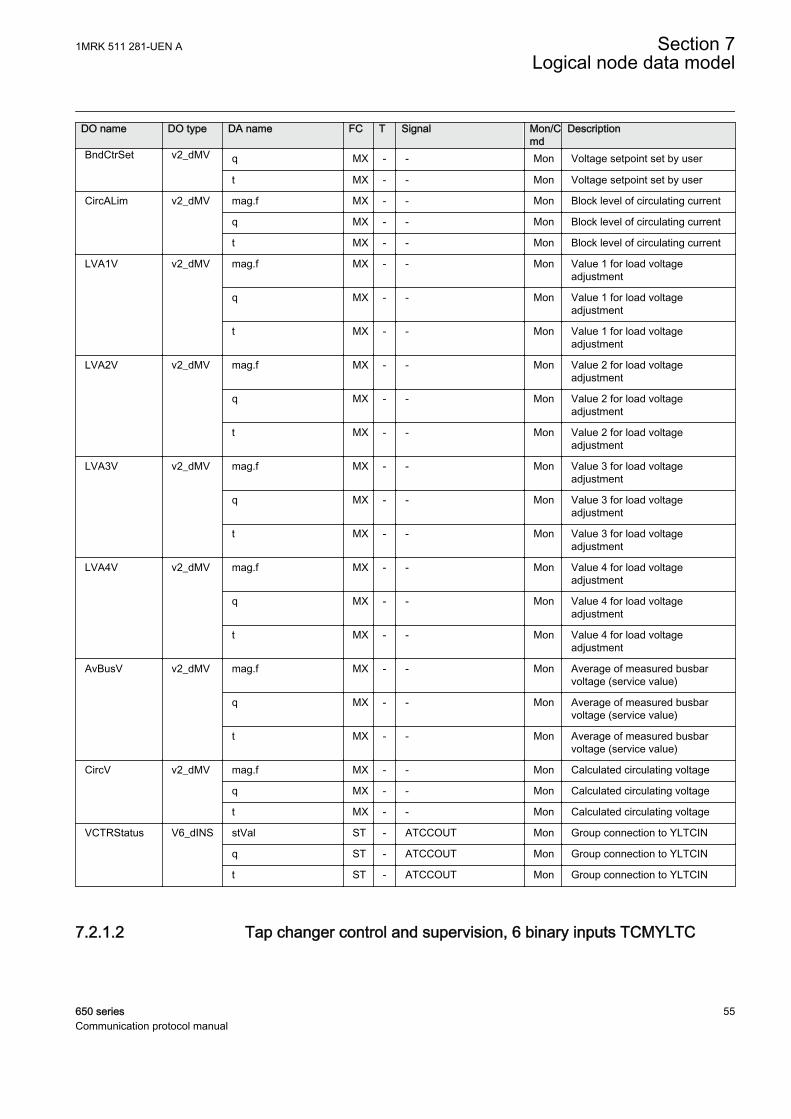
DO name DO type DA name FC T Signal Mon/Cmd
Description
BndCtrSet v2_dMV q MX - - Mon Voltage setpoint set by user
t MX - - Mon Voltage setpoint set by user
CircALim v2_dMV mag.f MX - - Mon Block level of circulating current
q MX - - Mon Block level of circulating current
t MX - - Mon Block level of circulating current
LVA1V v2_dMV mag.f MX - - Mon Value 1 for load voltageadjustment
q MX - - Mon Value 1 for load voltageadjustment
t MX - - Mon Value 1 for load voltageadjustment
LVA2V v2_dMV mag.f MX - - Mon Value 2 for load voltageadjustment
q MX - - Mon Value 2 for load voltageadjustment
t MX - - Mon Value 2 for load voltageadjustment
LVA3V v2_dMV mag.f MX - - Mon Value 3 for load voltageadjustment
q MX - - Mon Value 3 for load voltageadjustment
t MX - - Mon Value 3 for load voltageadjustment
LVA4V v2_dMV mag.f MX - - Mon Value 4 for load voltageadjustment
q MX - - Mon Value 4 for load voltageadjustment
t MX - - Mon Value 4 for load voltageadjustment
AvBusV v2_dMV mag.f MX - - Mon Average of measured busbarvoltage (service value)
q MX - - Mon Average of measured busbarvoltage (service value)
t MX - - Mon Average of measured busbarvoltage (service value)
CircV v2_dMV mag.f MX - - Mon Calculated circulating voltage
q MX - - Mon Calculated circulating voltage
t MX - - Mon Calculated circulating voltage
VCTRStatus V6_dINS stVal ST - ATCCOUT Mon Group connection to YLTCIN
q ST - ATCCOUT Mon Group connection to YLTCIN
t ST - ATCCOUT Mon Group connection to YLTCIN
7.2.1.2 Tap changer control and supervision, 6 binary inputs TCMYLTC
1MRK 511 281-UEN A Section 7Logical node data model
650 series 55Communication protocol manual
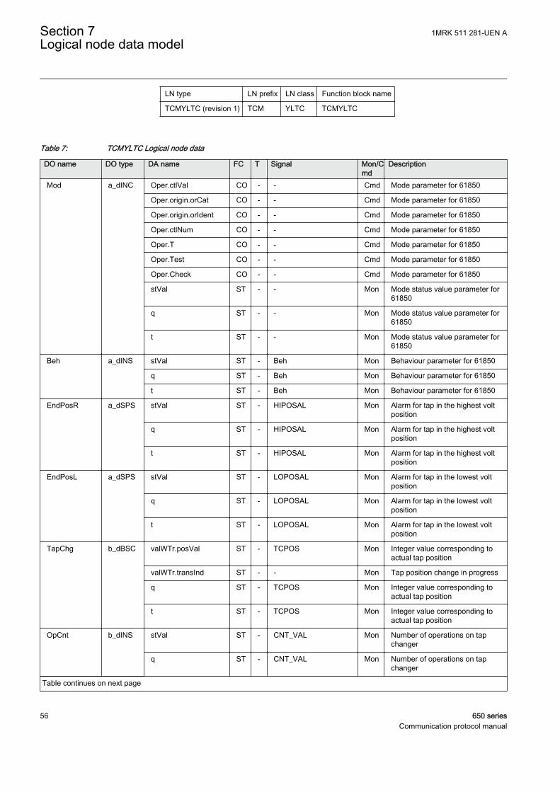
LN type LN prefix LN class Function block name
TCMYLTC (revision 1) TCM YLTC TCMYLTC
Table 7: TCMYLTC Logical node data
DO name DO type DA name FC T Signal Mon/Cmd
Description
Mod a_dINC Oper.ctlVal CO - - Cmd Mode parameter for 61850
Oper.origin.orCat CO - - Cmd Mode parameter for 61850
Oper.origin.orIdent CO - - Cmd Mode parameter for 61850
Oper.ctlNum CO - - Cmd Mode parameter for 61850
Oper.T CO - - Cmd Mode parameter for 61850
Oper.Test CO - - Cmd Mode parameter for 61850
Oper.Check CO - - Cmd Mode parameter for 61850
stVal ST - - Mon Mode status value parameter for61850
q ST - - Mon Mode status value parameter for61850
t ST - - Mon Mode status value parameter for61850
Beh a_dINS stVal ST - Beh Mon Behaviour parameter for 61850
q ST - Beh Mon Behaviour parameter for 61850
t ST - Beh Mon Behaviour parameter for 61850
EndPosR a_dSPS stVal ST - HIPOSAL Mon Alarm for tap in the highest voltposition
q ST - HIPOSAL Mon Alarm for tap in the highest voltposition
t ST - HIPOSAL Mon Alarm for tap in the highest voltposition
EndPosL a_dSPS stVal ST - LOPOSAL Mon Alarm for tap in the lowest voltposition
q ST - LOPOSAL Mon Alarm for tap in the lowest voltposition
t ST - LOPOSAL Mon Alarm for tap in the lowest voltposition
TapChg b_dBSC valWTr.posVal ST - TCPOS Mon Integer value corresponding toactual tap position
valWTr.transInd ST - - Mon Tap position change in progress
q ST - TCPOS Mon Integer value corresponding toactual tap position
t ST - TCPOS Mon Integer value corresponding toactual tap position
OpCnt b_dINS stVal ST - CNT_VAL Mon Number of operations on tapchanger
q ST - CNT_VAL Mon Number of operations on tapchanger
Table continues on next page
Section 7 1MRK 511 281-UEN ALogical node data model
56 650 seriesCommunication protocol manual
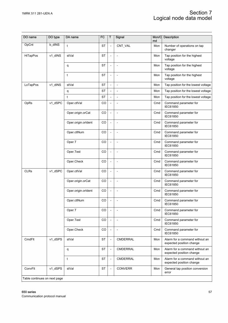
DO name DO type DA name FC T Signal Mon/Cmd
Description
OpCnt b_dINS t ST - CNT_VAL Mon Number of operations on tapchanger
HiTapPos v1_dINS stVal ST - - Mon Tap position for the highestvoltage
q ST - - Mon Tap position for the highestvoltage
t ST - - Mon Tap position for the highestvoltage
LoTapPos v1_dINS stVal ST - - Mon Tap position for the lowest voltage
q ST - - Mon Tap position for the lowest voltage
t ST - - Mon Tap position for the lowest voltage
OpRs v1_dSPC Oper.ctlVal CO - - Cmd Command parameter forIEC61850
Oper.origin.orCat CO - - Cmd Command parameter forIEC61850
Oper.origin.orIdent CO - - Cmd Command parameter forIEC61850
Oper.ctlNum CO - - Cmd Command parameter forIEC61850
Oper.T CO - - Cmd Command parameter forIEC61850
Oper.Test CO - - Cmd Command parameter forIEC61850
Oper.Check CO - - Cmd Command parameter forIEC61850
CLRs v1_dSPC Oper.ctlVal CO - - Cmd Command parameter forIEC61850
Oper.origin.orCat CO - - Cmd Command parameter forIEC61850
Oper.origin.orIdent CO - - Cmd Command parameter forIEC61850
Oper.ctlNum CO - - Cmd Command parameter forIEC61850
Oper.T CO - - Cmd Command parameter forIEC61850
Oper.Test CO - - Cmd Command parameter forIEC61850
Oper.Check CO - - Cmd Command parameter forIEC61850
CmdFlt v1_dSPS stVal ST - CMDERRAL Mon Alarm for a command without anexpected position change
q ST - CMDERRAL Mon Alarm for a command without anexpected position change
t ST - CMDERRAL Mon Alarm for a command without anexpected position change
ConvFlt v1_dSPS stVal ST - CONVERR Mon General tap position conversionerror
Table continues on next page
1MRK 511 281-UEN A Section 7Logical node data model
650 series 57Communication protocol manual

DO name DO type DA name FC T Signal Mon/Cmd
Description
ConvFlt v1_dSPS q ST - CONVERR Mon General tap position conversionerror
t ST - CONVERR Mon General tap position conversionerror
InvPosChg v1_dSPS stVal ST - INVALPOS Mon Last position change was aninvalid change
q ST - INVALPOS Mon Last position change was aninvalid change
t ST - INVALPOS Mon Last position change was aninvalid change
TapChgFlt v1_dSPS stVal ST - TCERRAL Mon Alarm for none or illegal tapposition change
q ST - TCERRAL Mon Alarm for none or illegal tapposition change
t ST - TCERRAL Mon Alarm for none or illegal tapposition change
TapPosFlt v1_dSPS stVal ST - POSERRAL Mon Alarm that indicates a problemwith the position indication
q ST - POSERRAL Mon Alarm that indicates a problemwith the position indication
t ST - POSERRAL Mon Alarm that indicates a problemwith the position indication
CLCnt v2_dMV mag.f MX - CLCNT_VAL Mon Remaining number of operationsat rated load
q MX - CLCNT_VAL Mon Remaining number of operationsat rated load
t MX - CLCNT_VAL Mon Remaining number of operationsat rated load
7.3 Logical nodes for control
7.3.1 Bay control CBAY
7.3.1.1 Bay control QCBAY
LN type LN prefix LN class Function block name
QCBAY (revision 1) Q CBAY QCBAY
Section 7 1MRK 511 281-UEN ALogical node data model
58 650 seriesCommunication protocol manual
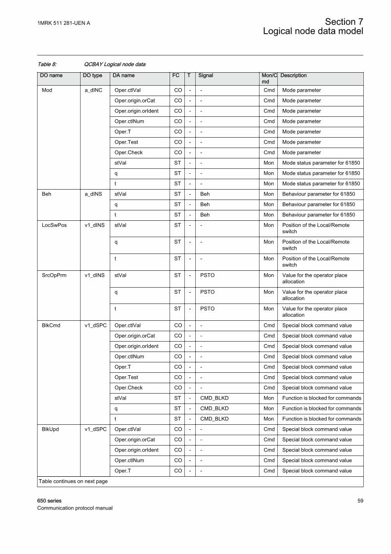
Table 8: QCBAY Logical node data
DO name DO type DA name FC T Signal Mon/Cmd
Description
Mod a_dINC Oper.ctlVal CO - - Cmd Mode parameter
Oper.origin.orCat CO - - Cmd Mode parameter
Oper.origin.orIdent CO - - Cmd Mode parameter
Oper.ctlNum CO - - Cmd Mode parameter
Oper.T CO - - Cmd Mode parameter
Oper.Test CO - - Cmd Mode parameter
Oper.Check CO - - Cmd Mode parameter
stVal ST - - Mon Mode status parameter for 61850
q ST - - Mon Mode status parameter for 61850
t ST - - Mon Mode status parameter for 61850
Beh a_dINS stVal ST - Beh Mon Behaviour parameter for 61850
q ST - Beh Mon Behaviour parameter for 61850
t ST - Beh Mon Behaviour parameter for 61850
LocSwPos v1_dINS stVal ST - - Mon Position of the Local/Remoteswitch
q ST - - Mon Position of the Local/Remoteswitch
t ST - - Mon Position of the Local/Remoteswitch
SrcOpPrm v1_dINS stVal ST - PSTO Mon Value for the operator placeallocation
q ST - PSTO Mon Value for the operator placeallocation
t ST - PSTO Mon Value for the operator placeallocation
BlkCmd v1_dSPC Oper.ctlVal CO - - Cmd Special block command value
Oper.origin.orCat CO - - Cmd Special block command value
Oper.origin.orIdent CO - - Cmd Special block command value
Oper.ctlNum CO - - Cmd Special block command value
Oper.T CO - - Cmd Special block command value
Oper.Test CO - - Cmd Special block command value
Oper.Check CO - - Cmd Special block command value
stVal ST - CMD_BLKD Mon Function is blocked for commands
q ST - CMD_BLKD Mon Function is blocked for commands
t ST - CMD_BLKD Mon Function is blocked for commands
BlkUpd v1_dSPC Oper.ctlVal CO - - Cmd Special block command value
Oper.origin.orCat CO - - Cmd Special block command value
Oper.origin.orIdent CO - - Cmd Special block command value
Oper.ctlNum CO - - Cmd Special block command value
Oper.T CO - - Cmd Special block command value
Table continues on next page
1MRK 511 281-UEN A Section 7Logical node data model
650 series 59Communication protocol manual
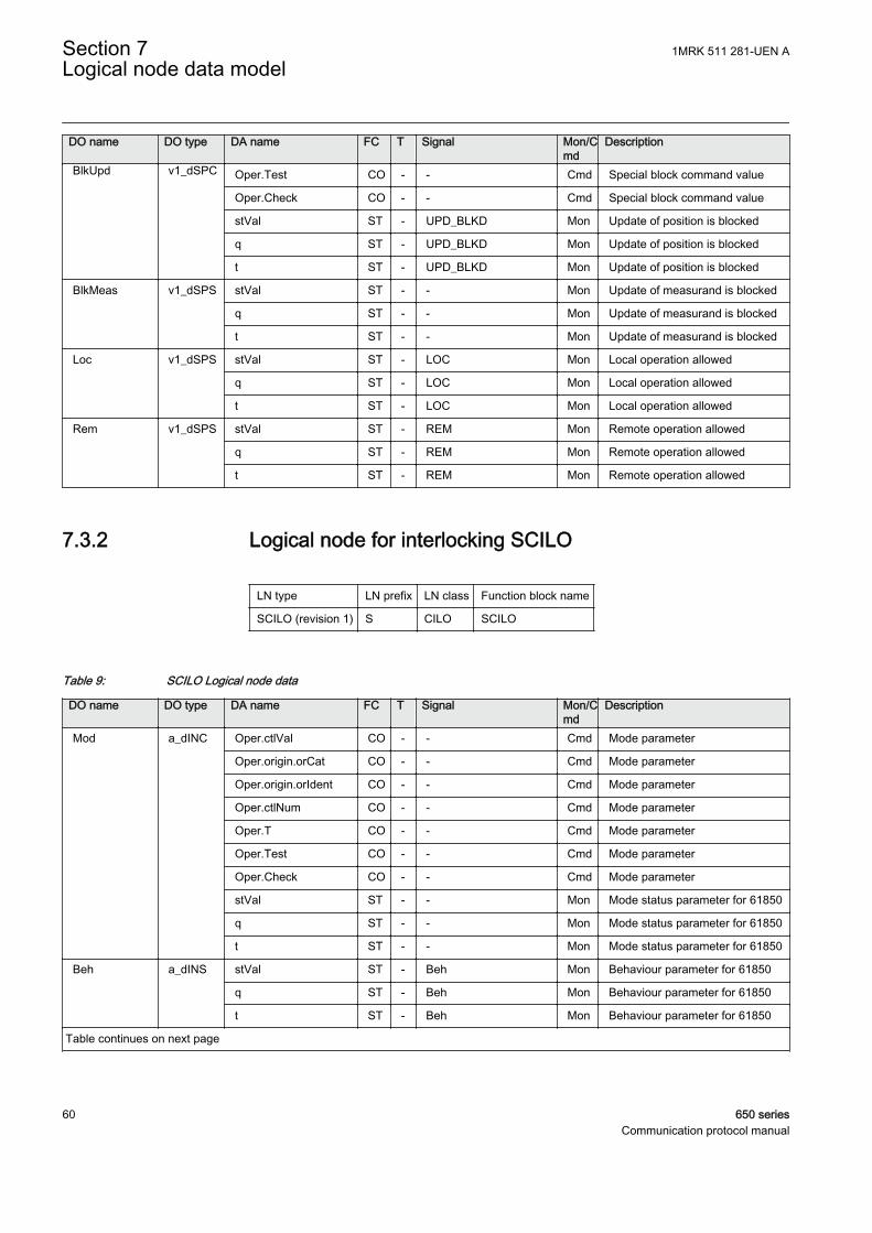
DO name DO type DA name FC T Signal Mon/Cmd
Description
BlkUpd v1_dSPC Oper.Test CO - - Cmd Special block command value
Oper.Check CO - - Cmd Special block command value
stVal ST - UPD_BLKD Mon Update of position is blocked
q ST - UPD_BLKD Mon Update of position is blocked
t ST - UPD_BLKD Mon Update of position is blocked
BlkMeas v1_dSPS stVal ST - - Mon Update of measurand is blocked
q ST - - Mon Update of measurand is blocked
t ST - - Mon Update of measurand is blocked
Loc v1_dSPS stVal ST - LOC Mon Local operation allowed
q ST - LOC Mon Local operation allowed
t ST - LOC Mon Local operation allowed
Rem v1_dSPS stVal ST - REM Mon Remote operation allowed
q ST - REM Mon Remote operation allowed
t ST - REM Mon Remote operation allowed
7.3.2 Logical node for interlocking SCILO
LN type LN prefix LN class Function block name
SCILO (revision 1) S CILO SCILO
Table 9: SCILO Logical node data
DO name DO type DA name FC T Signal Mon/Cmd
Description
Mod a_dINC Oper.ctlVal CO - - Cmd Mode parameter
Oper.origin.orCat CO - - Cmd Mode parameter
Oper.origin.orIdent CO - - Cmd Mode parameter
Oper.ctlNum CO - - Cmd Mode parameter
Oper.T CO - - Cmd Mode parameter
Oper.Test CO - - Cmd Mode parameter
Oper.Check CO - - Cmd Mode parameter
stVal ST - - Mon Mode status parameter for 61850
q ST - - Mon Mode status parameter for 61850
t ST - - Mon Mode status parameter for 61850
Beh a_dINS stVal ST - Beh Mon Behaviour parameter for 61850
q ST - Beh Mon Behaviour parameter for 61850
t ST - Beh Mon Behaviour parameter for 61850
Table continues on next page
Section 7 1MRK 511 281-UEN ALogical node data model
60 650 seriesCommunication protocol manual
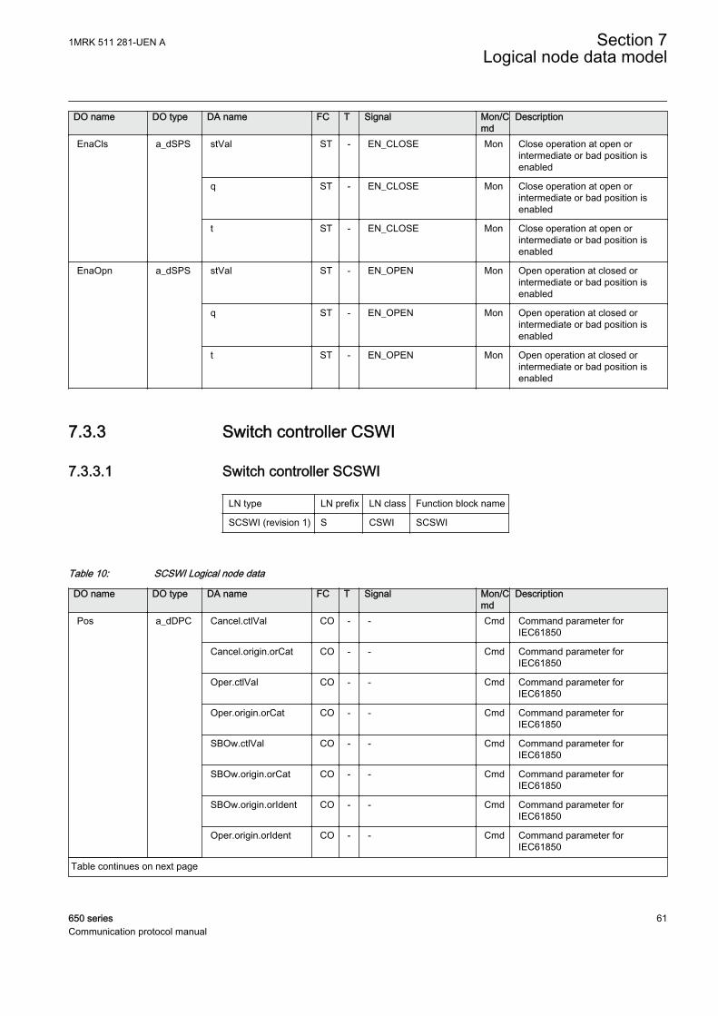
DO name DO type DA name FC T Signal Mon/Cmd
Description
EnaCls a_dSPS stVal ST - EN_CLOSE Mon Close operation at open orintermediate or bad position isenabled
q ST - EN_CLOSE Mon Close operation at open orintermediate or bad position isenabled
t ST - EN_CLOSE Mon Close operation at open orintermediate or bad position isenabled
EnaOpn a_dSPS stVal ST - EN_OPEN Mon Open operation at closed orintermediate or bad position isenabled
q ST - EN_OPEN Mon Open operation at closed orintermediate or bad position isenabled
t ST - EN_OPEN Mon Open operation at closed orintermediate or bad position isenabled
7.3.3 Switch controller CSWI
7.3.3.1 Switch controller SCSWI
LN type LN prefix LN class Function block name
SCSWI (revision 1) S CSWI SCSWI
Table 10: SCSWI Logical node data
DO name DO type DA name FC T Signal Mon/Cmd
Description
Pos a_dDPC Cancel.ctlVal CO - - Cmd Command parameter forIEC61850
Cancel.origin.orCat CO - - Cmd Command parameter forIEC61850
Oper.ctlVal CO - - Cmd Command parameter forIEC61850
Oper.origin.orCat CO - - Cmd Command parameter forIEC61850
SBOw.ctlVal CO - - Cmd Command parameter forIEC61850
SBOw.origin.orCat CO - - Cmd Command parameter forIEC61850
SBOw.origin.orIdent CO - - Cmd Command parameter forIEC61850
Oper.origin.orIdent CO - - Cmd Command parameter forIEC61850
Table continues on next page
1MRK 511 281-UEN A Section 7Logical node data model
650 series 61Communication protocol manual
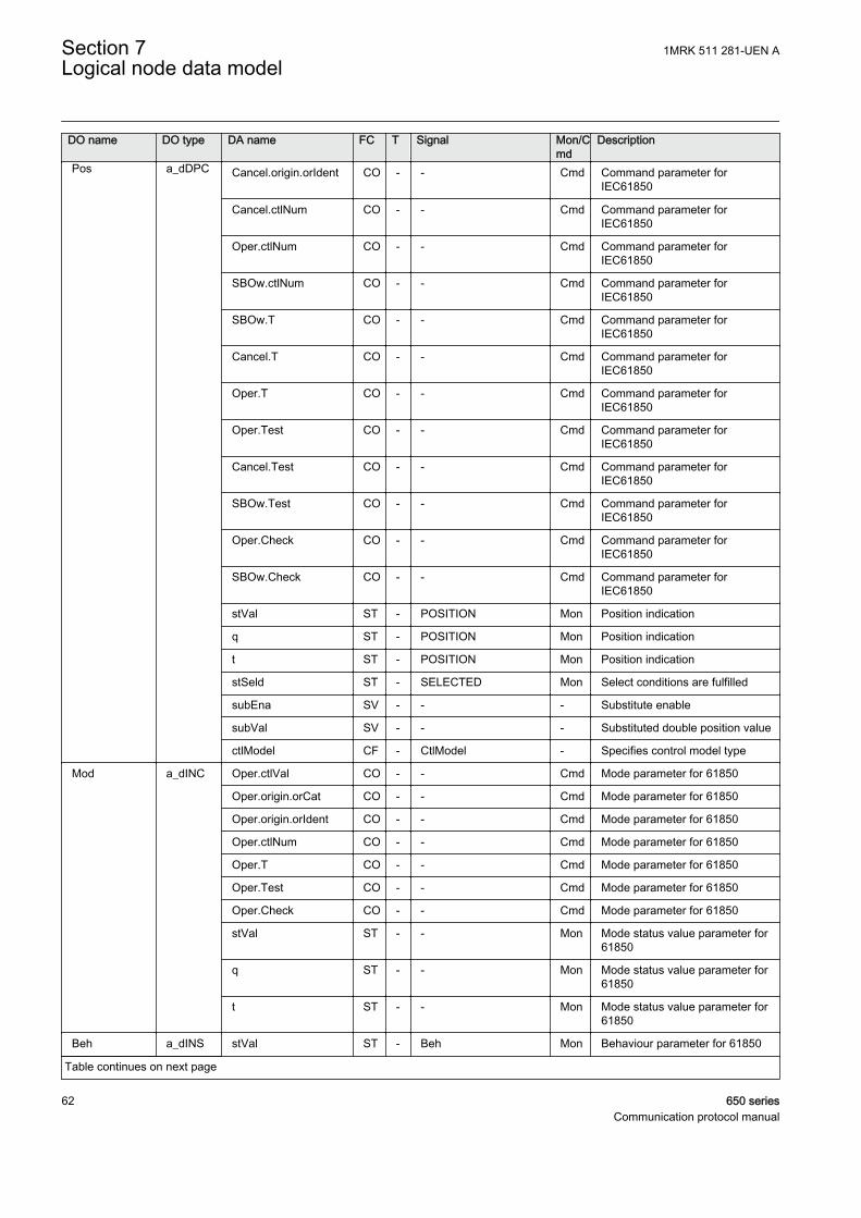
DO name DO type DA name FC T Signal Mon/Cmd
Description
Pos a_dDPC Cancel.origin.orIdent CO - - Cmd Command parameter forIEC61850
Cancel.ctlNum CO - - Cmd Command parameter forIEC61850
Oper.ctlNum CO - - Cmd Command parameter forIEC61850
SBOw.ctlNum CO - - Cmd Command parameter forIEC61850
SBOw.T CO - - Cmd Command parameter forIEC61850
Cancel.T CO - - Cmd Command parameter forIEC61850
Oper.T CO - - Cmd Command parameter forIEC61850
Oper.Test CO - - Cmd Command parameter forIEC61850
Cancel.Test CO - - Cmd Command parameter forIEC61850
SBOw.Test CO - - Cmd Command parameter forIEC61850
Oper.Check CO - - Cmd Command parameter forIEC61850
SBOw.Check CO - - Cmd Command parameter forIEC61850
stVal ST - POSITION Mon Position indication
q ST - POSITION Mon Position indication
t ST - POSITION Mon Position indication
stSeld ST - SELECTED Mon Select conditions are fulfilled
subEna SV - - - Substitute enable
subVal SV - - - Substituted double position value
ctlModel CF - CtlModel - Specifies control model type
Mod a_dINC Oper.ctlVal CO - - Cmd Mode parameter for 61850
Oper.origin.orCat CO - - Cmd Mode parameter for 61850
Oper.origin.orIdent CO - - Cmd Mode parameter for 61850
Oper.ctlNum CO - - Cmd Mode parameter for 61850
Oper.T CO - - Cmd Mode parameter for 61850
Oper.Test CO - - Cmd Mode parameter for 61850
Oper.Check CO - - Cmd Mode parameter for 61850
stVal ST - - Mon Mode status value parameter for61850
q ST - - Mon Mode status value parameter for61850
t ST - - Mon Mode status value parameter for61850
Beh a_dINS stVal ST - Beh Mon Behaviour parameter for 61850
Table continues on next page
Section 7 1MRK 511 281-UEN ALogical node data model
62 650 seriesCommunication protocol manual
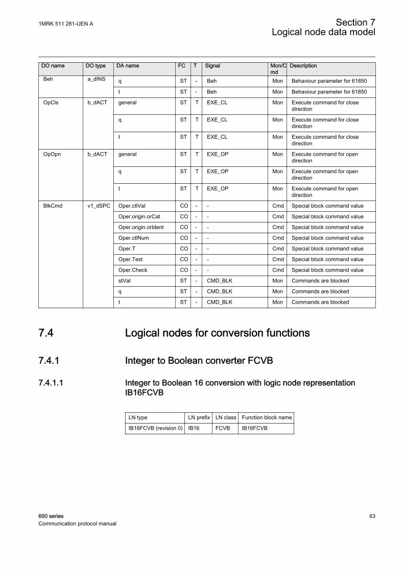
DO name DO type DA name FC T Signal Mon/Cmd
Description
Beh a_dINS q ST - Beh Mon Behaviour parameter for 61850
t ST - Beh Mon Behaviour parameter for 61850
OpCls b_dACT general ST T EXE_CL Mon Execute command for closedirection
q ST T EXE_CL Mon Execute command for closedirection
t ST T EXE_CL Mon Execute command for closedirection
OpOpn b_dACT general ST T EXE_OP Mon Execute command for opendirection
q ST T EXE_OP Mon Execute command for opendirection
t ST T EXE_OP Mon Execute command for opendirection
BlkCmd v1_dSPC Oper.ctlVal CO - - Cmd Special block command value
Oper.origin.orCat CO - - Cmd Special block command value
Oper.origin.orIdent CO - - Cmd Special block command value
Oper.ctlNum CO - - Cmd Special block command value
Oper.T CO - - Cmd Special block command value
Oper.Test CO - - Cmd Special block command value
Oper.Check CO - - Cmd Special block command value
stVal ST - CMD_BLK Mon Commands are blocked
q ST - CMD_BLK Mon Commands are blocked
t ST - CMD_BLK Mon Commands are blocked
7.4 Logical nodes for conversion functions
7.4.1 Integer to Boolean converter FCVB
7.4.1.1 Integer to Boolean 16 conversion with logic node representationIB16FCVB
LN type LN prefix LN class Function block name
IB16FCVB (revision 0) IB16 FCVB IB16FCVB
1MRK 511 281-UEN A Section 7Logical node data model
650 series 63Communication protocol manual
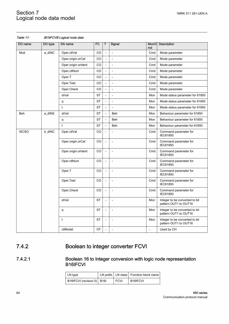
Table 11: IB16FCVB Logical node data
DO name DO type DA name FC T Signal Mon/Cmd
Description
Mod a_dINC Oper.ctlVal CO - - Cmd Mode parameter
Oper.origin.orCat CO - - Cmd Mode parameter
Oper.origin.orIdent CO - - Cmd Mode parameter
Oper.ctlNum CO - - Cmd Mode parameter
Oper.T CO - - Cmd Mode parameter
Oper.Test CO - - Cmd Mode parameter
Oper.Check CO - - Cmd Mode parameter
stVal ST - - Mon Mode status parameter for 61850
q ST - - Mon Mode status parameter for 61850
t ST - - Mon Mode status parameter for 61850
Beh a_dINS stVal ST - Beh Mon Behaviour parameter for 61850
q ST - Beh Mon Behaviour parameter for 61850
t ST - Beh Mon Behaviour parameter for 61850
ISCSO b_dINC Oper.ctlVal CO - - Cmd Command parameter forIEC61850
Oper.origin.orCat CO - - Cmd Command parameter forIEC61850
Oper.origin.orIdent CO - - Cmd Command parameter forIEC61850
Oper.ctlNum CO - - Cmd Command parameter forIEC61850
Oper.T CO - - Cmd Command parameter forIEC61850
Oper.Test CO - - Cmd Command parameter forIEC61850
Oper.Check CO - - Cmd Command parameter forIEC61850
stVal ST - - Mon Integer to be converted to bitpattern OUT1 to OUT16
q ST - - Mon Integer to be converted to bitpattern OUT1 to OUT16
t ST - - Mon Integer to be converted to bitpattern OUT1 to OUT16
ctlModel CF - - - Used by CH
7.4.2 Boolean to integer converter FCVI
7.4.2.1 Boolean 16 to Integer conversion with logic node representationB16IFCVI
LN type LN prefix LN class Function block name
B16IFCVI (revision 0) B16I FCVI B16IFCVI
Section 7 1MRK 511 281-UEN ALogical node data model
64 650 seriesCommunication protocol manual
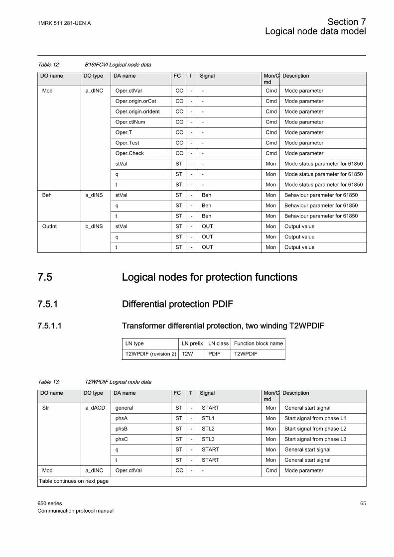
Table 12: B16IFCVI Logical node data
DO name DO type DA name FC T Signal Mon/Cmd
Description
Mod a_dINC Oper.ctlVal CO - - Cmd Mode parameter
Oper.origin.orCat CO - - Cmd Mode parameter
Oper.origin.orIdent CO - - Cmd Mode parameter
Oper.ctlNum CO - - Cmd Mode parameter
Oper.T CO - - Cmd Mode parameter
Oper.Test CO - - Cmd Mode parameter
Oper.Check CO - - Cmd Mode parameter
stVal ST - - Mon Mode status parameter for 61850
q ST - - Mon Mode status parameter for 61850
t ST - - Mon Mode status parameter for 61850
Beh a_dINS stVal ST - Beh Mon Behaviour parameter for 61850
q ST - Beh Mon Behaviour parameter for 61850
t ST - Beh Mon Behaviour parameter for 61850
OutInt b_dINS stVal ST - OUT Mon Output value
q ST - OUT Mon Output value
t ST - OUT Mon Output value
7.5 Logical nodes for protection functions
7.5.1 Differential protection PDIF
7.5.1.1 Transformer differential protection, two winding T2WPDIF
LN type LN prefix LN class Function block name
T2WPDIF (revision 2) T2W PDIF T2WPDIF
Table 13: T2WPDIF Logical node data
DO name DO type DA name FC T Signal Mon/Cmd
Description
Str a_dACD general ST - START Mon General start signal
phsA ST - STL1 Mon Start signal from phase L1
phsB ST - STL2 Mon Start signal from phase L2
phsC ST - STL3 Mon Start signal from phase L3
q ST - START Mon General start signal
t ST - START Mon General start signal
Mod a_dINC Oper.ctlVal CO - - Cmd Mode parameter
Table continues on next page
1MRK 511 281-UEN A Section 7Logical node data model
650 series 65Communication protocol manual
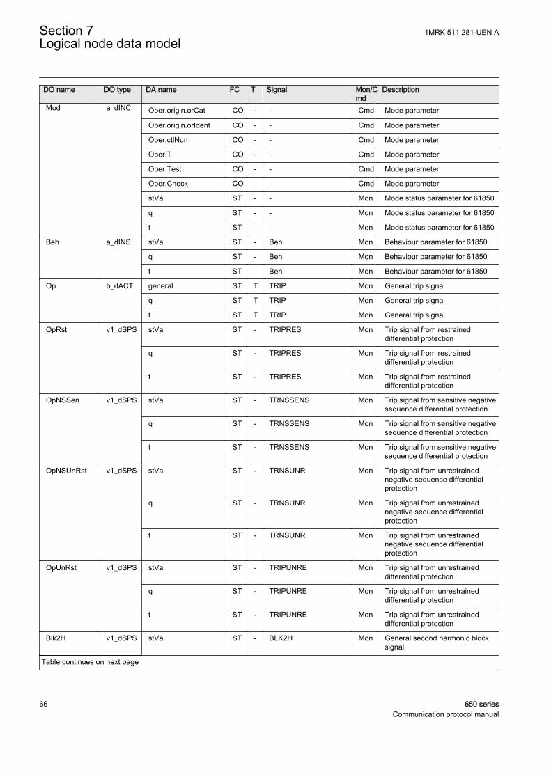
DO name DO type DA name FC T Signal Mon/Cmd
Description
Mod a_dINC Oper.origin.orCat CO - - Cmd Mode parameter
Oper.origin.orIdent CO - - Cmd Mode parameter
Oper.ctlNum CO - - Cmd Mode parameter
Oper.T CO - - Cmd Mode parameter
Oper.Test CO - - Cmd Mode parameter
Oper.Check CO - - Cmd Mode parameter
stVal ST - - Mon Mode status parameter for 61850
q ST - - Mon Mode status parameter for 61850
t ST - - Mon Mode status parameter for 61850
Beh a_dINS stVal ST - Beh Mon Behaviour parameter for 61850
q ST - Beh Mon Behaviour parameter for 61850
t ST - Beh Mon Behaviour parameter for 61850
Op b_dACT general ST T TRIP Mon General trip signal
q ST T TRIP Mon General trip signal
t ST T TRIP Mon General trip signal
OpRst v1_dSPS stVal ST - TRIPRES Mon Trip signal from restraineddifferential protection
q ST - TRIPRES Mon Trip signal from restraineddifferential protection
t ST - TRIPRES Mon Trip signal from restraineddifferential protection
OpNSSen v1_dSPS stVal ST - TRNSSENS Mon Trip signal from sensitive negativesequence differential protection
q ST - TRNSSENS Mon Trip signal from sensitive negativesequence differential protection
t ST - TRNSSENS Mon Trip signal from sensitive negativesequence differential protection
OpNSUnRst v1_dSPS stVal ST - TRNSUNR Mon Trip signal from unrestrainednegative sequence differentialprotection
q ST - TRNSUNR Mon Trip signal from unrestrainednegative sequence differentialprotection
t ST - TRNSUNR Mon Trip signal from unrestrainednegative sequence differentialprotection
OpUnRst v1_dSPS stVal ST - TRIPUNRE Mon Trip signal from unrestraineddifferential protection
q ST - TRIPUNRE Mon Trip signal from unrestraineddifferential protection
t ST - TRIPUNRE Mon Trip signal from unrestraineddifferential protection
Blk2H v1_dSPS stVal ST - BLK2H Mon General second harmonic blocksignal
Table continues on next page
Section 7 1MRK 511 281-UEN ALogical node data model
66 650 seriesCommunication protocol manual

DO name DO type DA name FC T Signal Mon/Cmd
Description
Blk2H v1_dSPS q ST - BLK2H Mon General second harmonic blocksignal
t ST - BLK2H Mon General second harmonic blocksignal
Blk5H v1_dSPS stVal ST - BLK5H Mon General fifth harmonic block signal
q ST - BLK5H Mon General fifth harmonic block signal
t ST - BLK5H Mon General fifth harmonic block signal
BlkWav v1_dSPS stVal ST - BLKWAV Mon General block signal fromwaveform criteria
q ST - BLKWAV Mon General block signal fromwaveform criteria
t ST - BLKWAV Mon General block signal fromwaveform criteria
ExFlt v1_dSPS stVal ST - - Mon Indication that external fault/disturbance has been detected
q ST - - Mon Indication that external fault/disturbance has been detected
t ST - - Mon Indication that external fault/disturbance has been detected
ItrFlt v1_dSPS stVal ST - - Mon Indication that internal fault hasbeen detected
q ST - - Mon Indication that internal fault hasbeen detected
t ST - - Mon Indication that internal fault hasbeen detected
DifAlm v1_dSPS stVal ST - IDALARM Mon General alarm for sustaineddifferential currents
q ST - IDALARM Mon General alarm for sustaineddifferential currents
t ST - IDALARM Mon General alarm for sustaineddifferential currents
7.5.1.2 Transformer differential protection, three winding T3WPDIF
LN type LN prefix LN class Function block name
T3WPDIF (revision 2) T3W PDIF T3WPDIF
Table 14: T3WPDIF Logical node data
DO name DO type DA name FC T Signal Mon/Cmd
Description
Str a_dACD general ST - START Mon General start signal
phsA ST - STL1 Mon Start signal from phase L1
phsB ST - STL2 Mon Start signal from phase L2
phsC ST - STL3 Mon Start signal from phase L3
Table continues on next page
1MRK 511 281-UEN A Section 7Logical node data model
650 series 67Communication protocol manual
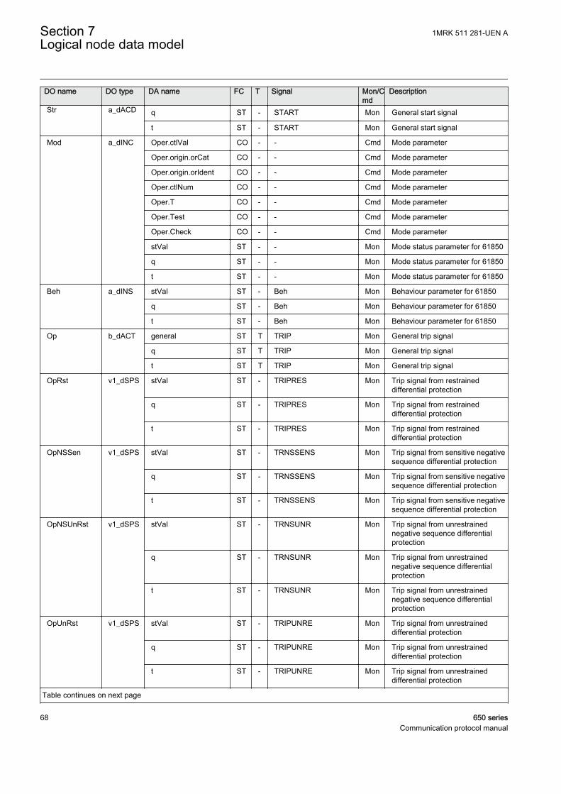
DO name DO type DA name FC T Signal Mon/Cmd
Description
Str a_dACD q ST - START Mon General start signal
t ST - START Mon General start signal
Mod a_dINC Oper.ctlVal CO - - Cmd Mode parameter
Oper.origin.orCat CO - - Cmd Mode parameter
Oper.origin.orIdent CO - - Cmd Mode parameter
Oper.ctlNum CO - - Cmd Mode parameter
Oper.T CO - - Cmd Mode parameter
Oper.Test CO - - Cmd Mode parameter
Oper.Check CO - - Cmd Mode parameter
stVal ST - - Mon Mode status parameter for 61850
q ST - - Mon Mode status parameter for 61850
t ST - - Mon Mode status parameter for 61850
Beh a_dINS stVal ST - Beh Mon Behaviour parameter for 61850
q ST - Beh Mon Behaviour parameter for 61850
t ST - Beh Mon Behaviour parameter for 61850
Op b_dACT general ST T TRIP Mon General trip signal
q ST T TRIP Mon General trip signal
t ST T TRIP Mon General trip signal
OpRst v1_dSPS stVal ST - TRIPRES Mon Trip signal from restraineddifferential protection
q ST - TRIPRES Mon Trip signal from restraineddifferential protection
t ST - TRIPRES Mon Trip signal from restraineddifferential protection
OpNSSen v1_dSPS stVal ST - TRNSSENS Mon Trip signal from sensitive negativesequence differential protection
q ST - TRNSSENS Mon Trip signal from sensitive negativesequence differential protection
t ST - TRNSSENS Mon Trip signal from sensitive negativesequence differential protection
OpNSUnRst v1_dSPS stVal ST - TRNSUNR Mon Trip signal from unrestrainednegative sequence differentialprotection
q ST - TRNSUNR Mon Trip signal from unrestrainednegative sequence differentialprotection
t ST - TRNSUNR Mon Trip signal from unrestrainednegative sequence differentialprotection
OpUnRst v1_dSPS stVal ST - TRIPUNRE Mon Trip signal from unrestraineddifferential protection
q ST - TRIPUNRE Mon Trip signal from unrestraineddifferential protection
t ST - TRIPUNRE Mon Trip signal from unrestraineddifferential protection
Table continues on next page
Section 7 1MRK 511 281-UEN ALogical node data model
68 650 seriesCommunication protocol manual
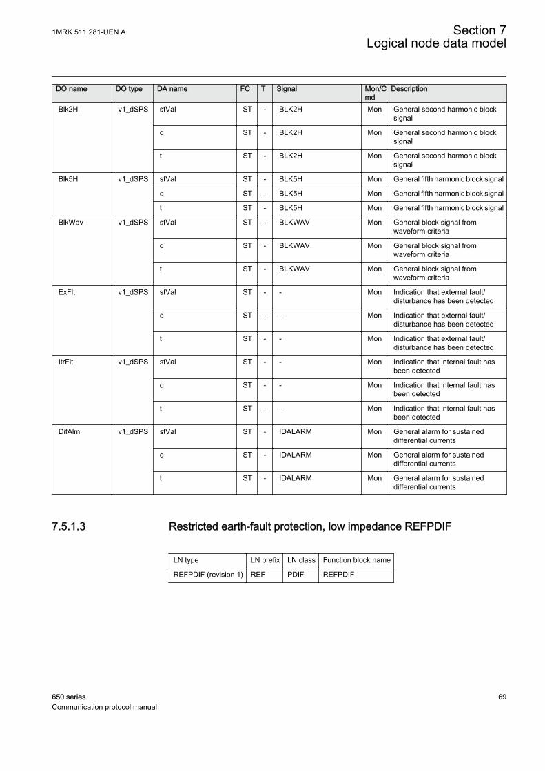
DO name DO type DA name FC T Signal Mon/Cmd
Description
Blk2H v1_dSPS stVal ST - BLK2H Mon General second harmonic blocksignal
q ST - BLK2H Mon General second harmonic blocksignal
t ST - BLK2H Mon General second harmonic blocksignal
Blk5H v1_dSPS stVal ST - BLK5H Mon General fifth harmonic block signal
q ST - BLK5H Mon General fifth harmonic block signal
t ST - BLK5H Mon General fifth harmonic block signal
BlkWav v1_dSPS stVal ST - BLKWAV Mon General block signal fromwaveform criteria
q ST - BLKWAV Mon General block signal fromwaveform criteria
t ST - BLKWAV Mon General block signal fromwaveform criteria
ExFlt v1_dSPS stVal ST - - Mon Indication that external fault/disturbance has been detected
q ST - - Mon Indication that external fault/disturbance has been detected
t ST - - Mon Indication that external fault/disturbance has been detected
ItrFlt v1_dSPS stVal ST - - Mon Indication that internal fault hasbeen detected
q ST - - Mon Indication that internal fault hasbeen detected
t ST - - Mon Indication that internal fault hasbeen detected
DifAlm v1_dSPS stVal ST - IDALARM Mon General alarm for sustaineddifferential currents
q ST - IDALARM Mon General alarm for sustaineddifferential currents
t ST - IDALARM Mon General alarm for sustaineddifferential currents
7.5.1.3 Restricted earth-fault protection, low impedance REFPDIF
LN type LN prefix LN class Function block name
REFPDIF (revision 1) REF PDIF REFPDIF
1MRK 511 281-UEN A Section 7Logical node data model
650 series 69Communication protocol manual
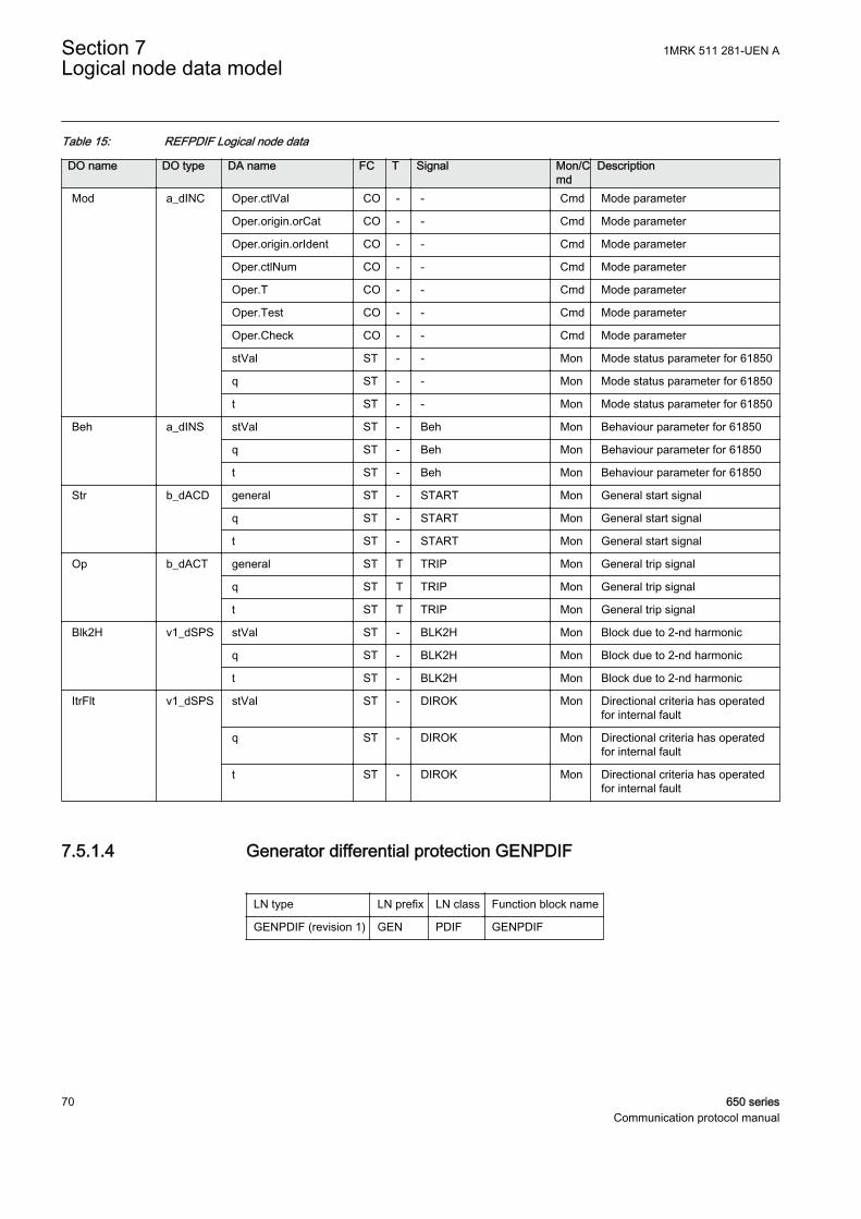
Table 15: REFPDIF Logical node data
DO name DO type DA name FC T Signal Mon/Cmd
Description
Mod a_dINC Oper.ctlVal CO - - Cmd Mode parameter
Oper.origin.orCat CO - - Cmd Mode parameter
Oper.origin.orIdent CO - - Cmd Mode parameter
Oper.ctlNum CO - - Cmd Mode parameter
Oper.T CO - - Cmd Mode parameter
Oper.Test CO - - Cmd Mode parameter
Oper.Check CO - - Cmd Mode parameter
stVal ST - - Mon Mode status parameter for 61850
q ST - - Mon Mode status parameter for 61850
t ST - - Mon Mode status parameter for 61850
Beh a_dINS stVal ST - Beh Mon Behaviour parameter for 61850
q ST - Beh Mon Behaviour parameter for 61850
t ST - Beh Mon Behaviour parameter for 61850
Str b_dACD general ST - START Mon General start signal
q ST - START Mon General start signal
t ST - START Mon General start signal
Op b_dACT general ST T TRIP Mon General trip signal
q ST T TRIP Mon General trip signal
t ST T TRIP Mon General trip signal
Blk2H v1_dSPS stVal ST - BLK2H Mon Block due to 2-nd harmonic
q ST - BLK2H Mon Block due to 2-nd harmonic
t ST - BLK2H Mon Block due to 2-nd harmonic
ItrFlt v1_dSPS stVal ST - DIROK Mon Directional criteria has operatedfor internal fault
q ST - DIROK Mon Directional criteria has operatedfor internal fault
t ST - DIROK Mon Directional criteria has operatedfor internal fault
7.5.1.4 Generator differential protection GENPDIF
LN type LN prefix LN class Function block name
GENPDIF (revision 1) GEN PDIF GENPDIF
Section 7 1MRK 511 281-UEN ALogical node data model
70 650 seriesCommunication protocol manual
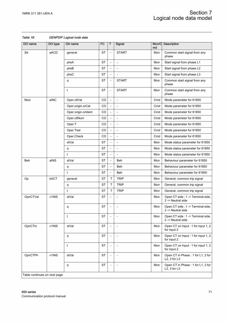
Table 16: GENPDIF Logical node data
DO name DO type DA name FC T Signal Mon/Cmd
Description
Str aACD general ST - START Mon Common start signal from anyphase
phsA ST - - Mon Start signal from phase L1
phsB ST - - Mon Start signal from phase L2
phsC ST - - Mon Start signal from phase L3
q ST - START Mon Common start signal from anyphase
t ST - START Mon Common start signal from anyphase
Mod aINC Oper.ctlVal CO - - Cmd Mode parameter for 61850
Oper.origin.orCat CO - - Cmd Mode parameter for 61850
Oper.origin.orIdent CO - - Cmd Mode parameter for 61850
Oper.ctlNum CO - - Cmd Mode parameter for 61850
Oper.T CO - - Cmd Mode parameter for 61850
Oper.Test CO - - Cmd Mode parameter for 61850
Oper.Check CO - - Cmd Mode parameter for 61850
stVal ST - - Mon Mode status parameter for 61850
q ST - - Mon Mode status parameter for 61850
t ST - - Mon Mode status parameter for 61850
Beh aINS stVal ST - Beh Mon Behaviour parameter for 61850
q ST - Beh Mon Behaviour parameter for 61850
t ST - Beh Mon Behaviour parameter for 61850
Op bACT general ST T TRIP Mon General, common trip signal
q ST T TRIP Mon General, common trip signal
t ST T TRIP Mon General, common trip signal
OpnCTVal v1INS stVal ST - - Mon Open CT side : 1 -> Terminal side,2 -> Neutral side
q ST - - Mon Open CT side : 1 -> Terminal side,2 -> Neutral side
t ST - - Mon Open CT side : 1 -> Terminal side,2 -> Neutral side
OpnCTIn v1INS stVal ST - - Mon Open CT on Input : 1 for input 1, 2for input 2
q ST - - Mon Open CT on Input : 1 for input 1, 2for input 2
t ST - - Mon Open CT on Input : 1 for input 1, 2for input 2
OpnCTPh v1INS stVal ST - - Mon Open CT in Phase : 1 for L1, 2 forL2, 3 for L3
q ST - - Mon Open CT in Phase : 1 for L1, 2 forL2, 3 for L3
Table continues on next page
1MRK 511 281-UEN A Section 7Logical node data model
650 series 71Communication protocol manual
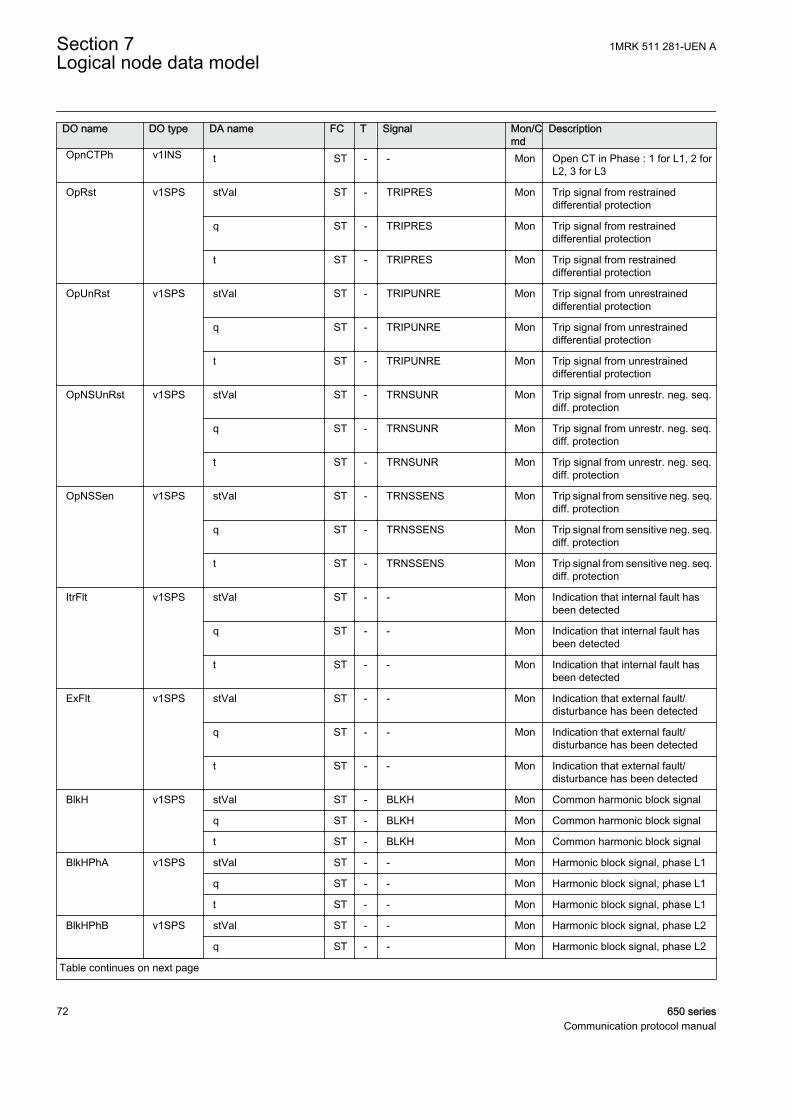
DO name DO type DA name FC T Signal Mon/Cmd
Description
OpnCTPh v1INS t ST - - Mon Open CT in Phase : 1 for L1, 2 forL2, 3 for L3
OpRst v1SPS stVal ST - TRIPRES Mon Trip signal from restraineddifferential protection
q ST - TRIPRES Mon Trip signal from restraineddifferential protection
t ST - TRIPRES Mon Trip signal from restraineddifferential protection
OpUnRst v1SPS stVal ST - TRIPUNRE Mon Trip signal from unrestraineddifferential protection
q ST - TRIPUNRE Mon Trip signal from unrestraineddifferential protection
t ST - TRIPUNRE Mon Trip signal from unrestraineddifferential protection
OpNSUnRst v1SPS stVal ST - TRNSUNR Mon Trip signal from unrestr. neg. seq.diff. protection
q ST - TRNSUNR Mon Trip signal from unrestr. neg. seq.diff. protection
t ST - TRNSUNR Mon Trip signal from unrestr. neg. seq.diff. protection
OpNSSen v1SPS stVal ST - TRNSSENS Mon Trip signal from sensitive neg. seq.diff. protection
q ST - TRNSSENS Mon Trip signal from sensitive neg. seq.diff. protection
t ST - TRNSSENS Mon Trip signal from sensitive neg. seq.diff. protection
ItrFlt v1SPS stVal ST - - Mon Indication that internal fault hasbeen detected
q ST - - Mon Indication that internal fault hasbeen detected
t ST - - Mon Indication that internal fault hasbeen detected
ExFlt v1SPS stVal ST - - Mon Indication that external fault/disturbance has been detected
q ST - - Mon Indication that external fault/disturbance has been detected
t ST - - Mon Indication that external fault/disturbance has been detected
BlkH v1SPS stVal ST - BLKH Mon Common harmonic block signal
q ST - BLKH Mon Common harmonic block signal
t ST - BLKH Mon Common harmonic block signal
BlkHPhA v1SPS stVal ST - - Mon Harmonic block signal, phase L1
q ST - - Mon Harmonic block signal, phase L1
t ST - - Mon Harmonic block signal, phase L1
BlkHPhB v1SPS stVal ST - - Mon Harmonic block signal, phase L2
q ST - - Mon Harmonic block signal, phase L2
Table continues on next page
Section 7 1MRK 511 281-UEN ALogical node data model
72 650 seriesCommunication protocol manual
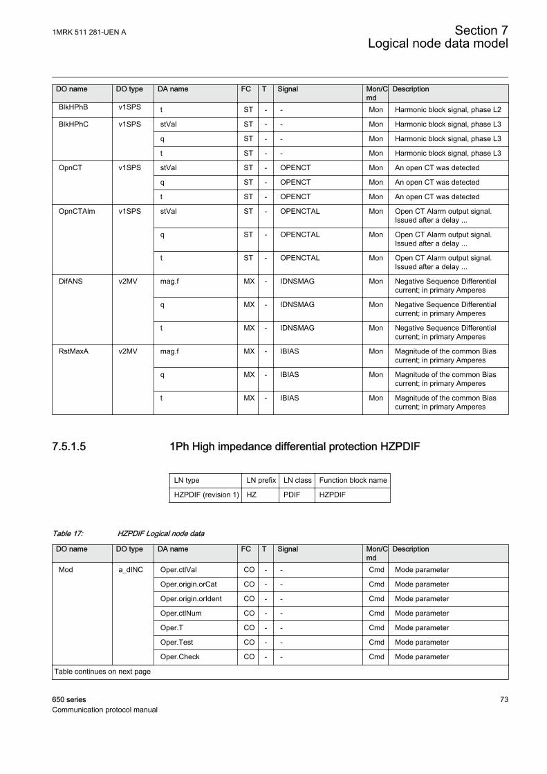
DO name DO type DA name FC T Signal Mon/Cmd
Description
BlkHPhB v1SPS t ST - - Mon Harmonic block signal, phase L2
BlkHPhC v1SPS stVal ST - - Mon Harmonic block signal, phase L3
q ST - - Mon Harmonic block signal, phase L3
t ST - - Mon Harmonic block signal, phase L3
OpnCT v1SPS stVal ST - OPENCT Mon An open CT was detected
q ST - OPENCT Mon An open CT was detected
t ST - OPENCT Mon An open CT was detected
OpnCTAlm v1SPS stVal ST - OPENCTAL Mon Open CT Alarm output signal.Issued after a delay ...
q ST - OPENCTAL Mon Open CT Alarm output signal.Issued after a delay ...
t ST - OPENCTAL Mon Open CT Alarm output signal.Issued after a delay ...
DifANS v2MV mag.f MX - IDNSMAG Mon Negative Sequence Differentialcurrent; in primary Amperes
q MX - IDNSMAG Mon Negative Sequence Differentialcurrent; in primary Amperes
t MX - IDNSMAG Mon Negative Sequence Differentialcurrent; in primary Amperes
RstMaxA v2MV mag.f MX - IBIAS Mon Magnitude of the common Biascurrent; in primary Amperes
q MX - IBIAS Mon Magnitude of the common Biascurrent; in primary Amperes
t MX - IBIAS Mon Magnitude of the common Biascurrent; in primary Amperes
7.5.1.5 1Ph High impedance differential protection HZPDIF
LN type LN prefix LN class Function block name
HZPDIF (revision 1) HZ PDIF HZPDIF
Table 17: HZPDIF Logical node data
DO name DO type DA name FC T Signal Mon/Cmd
Description
Mod a_dINC Oper.ctlVal CO - - Cmd Mode parameter
Oper.origin.orCat CO - - Cmd Mode parameter
Oper.origin.orIdent CO - - Cmd Mode parameter
Oper.ctlNum CO - - Cmd Mode parameter
Oper.T CO - - Cmd Mode parameter
Oper.Test CO - - Cmd Mode parameter
Oper.Check CO - - Cmd Mode parameter
Table continues on next page
1MRK 511 281-UEN A Section 7Logical node data model
650 series 73Communication protocol manual
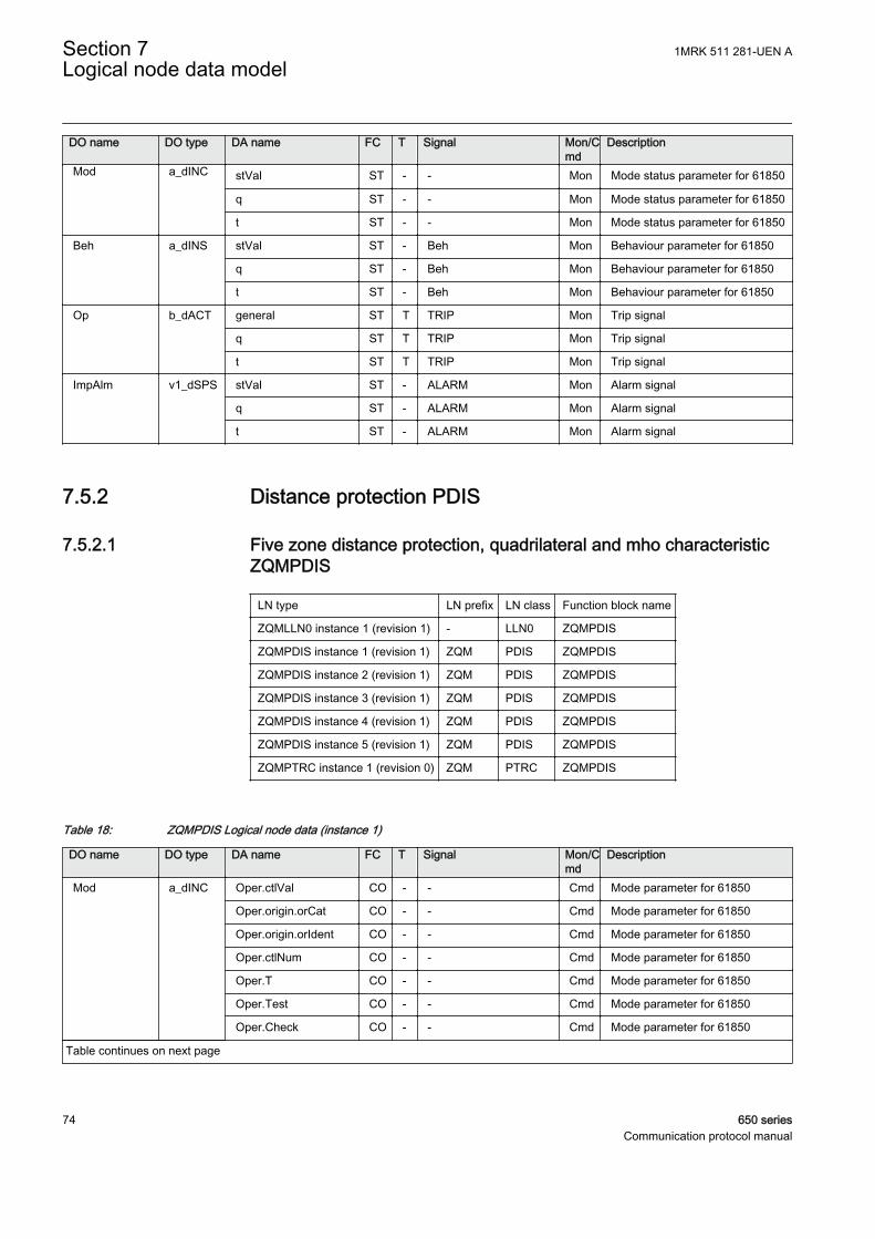
DO name DO type DA name FC T Signal Mon/Cmd
Description
Mod a_dINC stVal ST - - Mon Mode status parameter for 61850
q ST - - Mon Mode status parameter for 61850
t ST - - Mon Mode status parameter for 61850
Beh a_dINS stVal ST - Beh Mon Behaviour parameter for 61850
q ST - Beh Mon Behaviour parameter for 61850
t ST - Beh Mon Behaviour parameter for 61850
Op b_dACT general ST T TRIP Mon Trip signal
q ST T TRIP Mon Trip signal
t ST T TRIP Mon Trip signal
ImpAlm v1_dSPS stVal ST - ALARM Mon Alarm signal
q ST - ALARM Mon Alarm signal
t ST - ALARM Mon Alarm signal
7.5.2 Distance protection PDIS
7.5.2.1 Five zone distance protection, quadrilateral and mho characteristicZQMPDIS
LN type LN prefix LN class Function block name
ZQMLLN0 instance 1 (revision 1) - LLN0 ZQMPDIS
ZQMPDIS instance 1 (revision 1) ZQM PDIS ZQMPDIS
ZQMPDIS instance 2 (revision 1) ZQM PDIS ZQMPDIS
ZQMPDIS instance 3 (revision 1) ZQM PDIS ZQMPDIS
ZQMPDIS instance 4 (revision 1) ZQM PDIS ZQMPDIS
ZQMPDIS instance 5 (revision 1) ZQM PDIS ZQMPDIS
ZQMPTRC instance 1 (revision 0) ZQM PTRC ZQMPDIS
Table 18: ZQMPDIS Logical node data (instance 1)
DO name DO type DA name FC T Signal Mon/Cmd
Description
Mod a_dINC Oper.ctlVal CO - - Cmd Mode parameter for 61850
Oper.origin.orCat CO - - Cmd Mode parameter for 61850
Oper.origin.orIdent CO - - Cmd Mode parameter for 61850
Oper.ctlNum CO - - Cmd Mode parameter for 61850
Oper.T CO - - Cmd Mode parameter for 61850
Oper.Test CO - - Cmd Mode parameter for 61850
Oper.Check CO - - Cmd Mode parameter for 61850
Table continues on next page
Section 7 1MRK 511 281-UEN ALogical node data model
74 650 seriesCommunication protocol manual
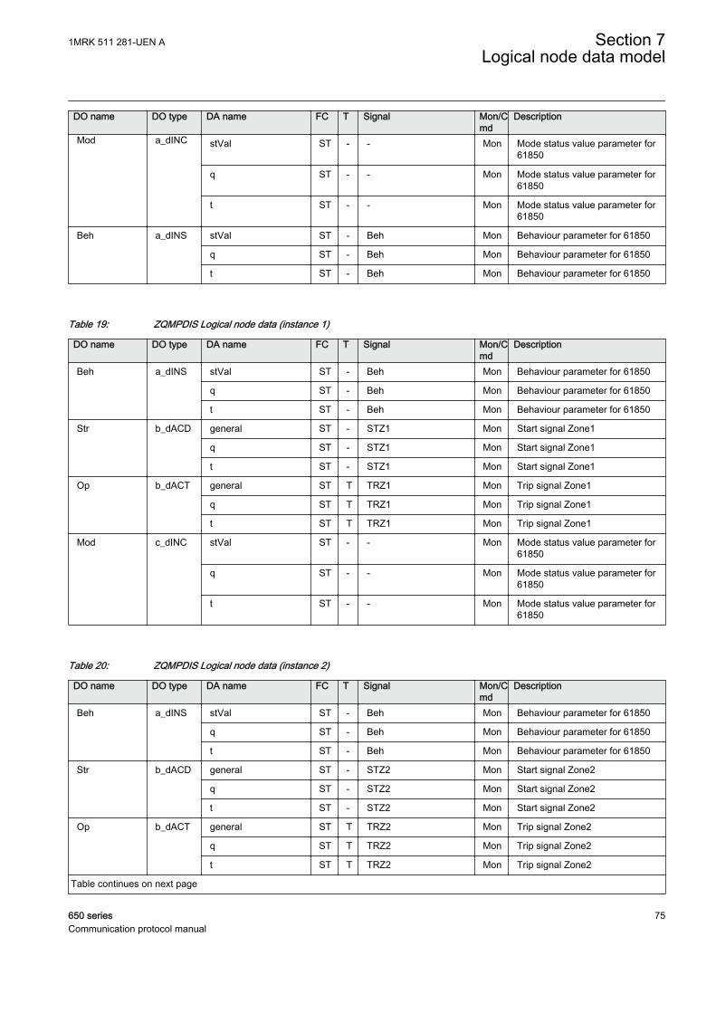
DO name DO type DA name FC T Signal Mon/Cmd
Description
Mod a_dINC stVal ST - - Mon Mode status value parameter for61850
q ST - - Mon Mode status value parameter for61850
t ST - - Mon Mode status value parameter for61850
Beh a_dINS stVal ST - Beh Mon Behaviour parameter for 61850
q ST - Beh Mon Behaviour parameter for 61850
t ST - Beh Mon Behaviour parameter for 61850
Table 19: ZQMPDIS Logical node data (instance 1)
DO name DO type DA name FC T Signal Mon/Cmd
Description
Beh a_dINS stVal ST - Beh Mon Behaviour parameter for 61850
q ST - Beh Mon Behaviour parameter for 61850
t ST - Beh Mon Behaviour parameter for 61850
Str b_dACD general ST - STZ1 Mon Start signal Zone1
q ST - STZ1 Mon Start signal Zone1
t ST - STZ1 Mon Start signal Zone1
Op b_dACT general ST T TRZ1 Mon Trip signal Zone1
q ST T TRZ1 Mon Trip signal Zone1
t ST T TRZ1 Mon Trip signal Zone1
Mod c_dINC stVal ST - - Mon Mode status value parameter for61850
q ST - - Mon Mode status value parameter for61850
t ST - - Mon Mode status value parameter for61850
Table 20: ZQMPDIS Logical node data (instance 2)
DO name DO type DA name FC T Signal Mon/Cmd
Description
Beh a_dINS stVal ST - Beh Mon Behaviour parameter for 61850
q ST - Beh Mon Behaviour parameter for 61850
t ST - Beh Mon Behaviour parameter for 61850
Str b_dACD general ST - STZ2 Mon Start signal Zone2
q ST - STZ2 Mon Start signal Zone2
t ST - STZ2 Mon Start signal Zone2
Op b_dACT general ST T TRZ2 Mon Trip signal Zone2
q ST T TRZ2 Mon Trip signal Zone2
t ST T TRZ2 Mon Trip signal Zone2
Table continues on next page
1MRK 511 281-UEN A Section 7Logical node data model
650 series 75Communication protocol manual
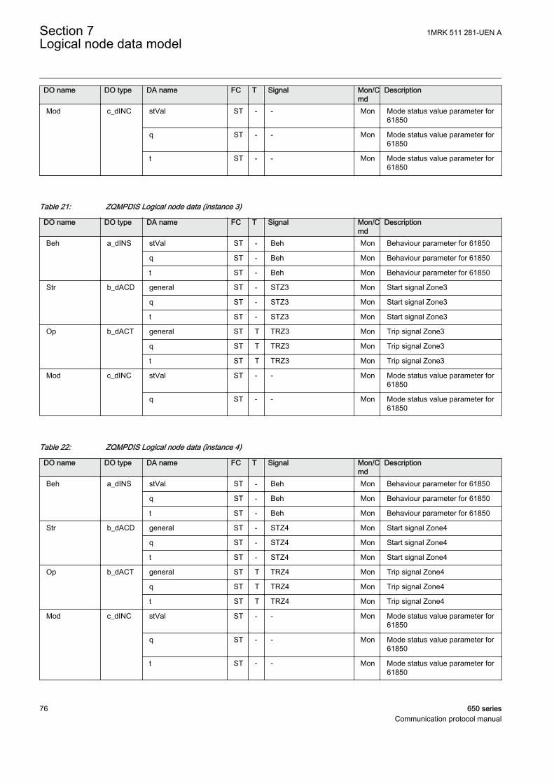
DO name DO type DA name FC T Signal Mon/Cmd
Description
Mod c_dINC stVal ST - - Mon Mode status value parameter for61850
q ST - - Mon Mode status value parameter for61850
t ST - - Mon Mode status value parameter for61850
Table 21: ZQMPDIS Logical node data (instance 3)
DO name DO type DA name FC T Signal Mon/Cmd
Description
Beh a_dINS stVal ST - Beh Mon Behaviour parameter for 61850
q ST - Beh Mon Behaviour parameter for 61850
t ST - Beh Mon Behaviour parameter for 61850
Str b_dACD general ST - STZ3 Mon Start signal Zone3
q ST - STZ3 Mon Start signal Zone3
t ST - STZ3 Mon Start signal Zone3
Op b_dACT general ST T TRZ3 Mon Trip signal Zone3
q ST T TRZ3 Mon Trip signal Zone3
t ST T TRZ3 Mon Trip signal Zone3
Mod c_dINC stVal ST - - Mon Mode status value parameter for61850
q ST - - Mon Mode status value parameter for61850
Table 22: ZQMPDIS Logical node data (instance 4)
DO name DO type DA name FC T Signal Mon/Cmd
Description
Beh a_dINS stVal ST - Beh Mon Behaviour parameter for 61850
q ST - Beh Mon Behaviour parameter for 61850
t ST - Beh Mon Behaviour parameter for 61850
Str b_dACD general ST - STZ4 Mon Start signal Zone4
q ST - STZ4 Mon Start signal Zone4
t ST - STZ4 Mon Start signal Zone4
Op b_dACT general ST T TRZ4 Mon Trip signal Zone4
q ST T TRZ4 Mon Trip signal Zone4
t ST T TRZ4 Mon Trip signal Zone4
Mod c_dINC stVal ST - - Mon Mode status value parameter for61850
q ST - - Mon Mode status value parameter for61850
t ST - - Mon Mode status value parameter for61850
Section 7 1MRK 511 281-UEN ALogical node data model
76 650 seriesCommunication protocol manual
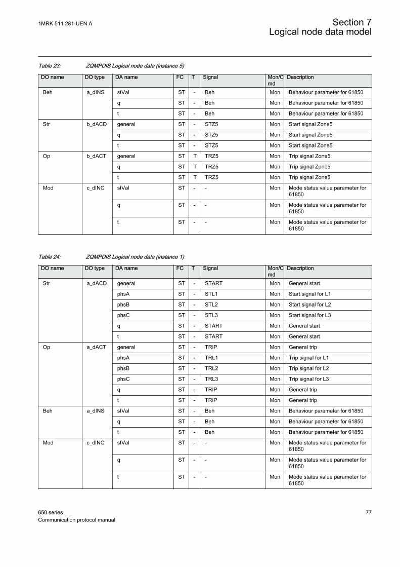
Table 23: ZQMPDIS Logical node data (instance 5)
DO name DO type DA name FC T Signal Mon/Cmd
Description
Beh a_dINS stVal ST - Beh Mon Behaviour parameter for 61850
q ST - Beh Mon Behaviour parameter for 61850
t ST - Beh Mon Behaviour parameter for 61850
Str b_dACD general ST - STZ5 Mon Start signal Zone5
q ST - STZ5 Mon Start signal Zone5
t ST - STZ5 Mon Start signal Zone5
Op b_dACT general ST T TRZ5 Mon Trip signal Zone5
q ST T TRZ5 Mon Trip signal Zone5
t ST T TRZ5 Mon Trip signal Zone5
Mod c_dINC stVal ST - - Mon Mode status value parameter for61850
q ST - - Mon Mode status value parameter for61850
t ST - - Mon Mode status value parameter for61850
Table 24: ZQMPDIS Logical node data (instance 1)
DO name DO type DA name FC T Signal Mon/Cmd
Description
Str a_dACD general ST - START Mon General start
phsA ST - STL1 Mon Start signal for L1
phsB ST - STL2 Mon Start signal for L2
phsC ST - STL3 Mon Start signal for L3
q ST - START Mon General start
t ST - START Mon General start
Op a_dACT general ST - TRIP Mon General trip
phsA ST - TRL1 Mon Trip signal for L1
phsB ST - TRL2 Mon Trip signal for L2
phsC ST - TRL3 Mon Trip signal for L3
q ST - TRIP Mon General trip
t ST - TRIP Mon General trip
Beh a_dINS stVal ST - Beh Mon Behaviour parameter for 61850
q ST - Beh Mon Behaviour parameter for 61850
t ST - Beh Mon Behaviour parameter for 61850
Mod c_dINC stVal ST - - Mon Mode status value parameter for61850
q ST - - Mon Mode status value parameter for61850
t ST - - Mon Mode status value parameter for61850
1MRK 511 281-UEN A Section 7Logical node data model
650 series 77Communication protocol manual
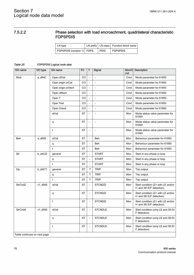
7.5.2.2 Phase selection with load encroachment, quadrilateral characteristicFDPSPDIS
LN type LN prefix LN class Function block name
FDPSPDIS (revision 1) FDPS PDIS FDPSPDIS
Table 25: FDPSPDIS Logical node data
DO name DO type DA name FC T Signal Mon/Cmd
Description
Mod a_dINC Oper.ctlVal CO - - Cmd Mode parameter for 61850
Oper.origin.orCat CO - - Cmd Mode parameter for 61850
Oper.origin.orIdent CO - - Cmd Mode parameter for 61850
Oper.ctlNum CO - - Cmd Mode parameter for 61850
Oper.T CO - - Cmd Mode parameter for 61850
Oper.Test CO - - Cmd Mode parameter for 61850
Oper.Check CO - - Cmd Mode parameter for 61850
stVal ST - - Mon Mode status value parameter for61850
q ST - - Mon Mode status value parameter for61850
t ST - - Mon Mode status value parameter for61850
Beh a_dINS stVal ST - Beh Mon Behaviour parameter for 61850
q ST - Beh Mon Behaviour parameter for 61850
t ST - Beh Mon Behaviour parameter for 61850
Str b_dACD general ST - START Mon Start in any phase or loop
q ST - START Mon Start in any phase or loop
t ST - START Mon Start in any phase or loop
Op b_dACT general ST T TRIP Mon Trip output
q ST T TRIP Mon Trip output
t ST T TRIP Mon Trip output
StrCndZ v1_dINS stVal ST - STCNDZI Mon Start condition (Z< with LE and/orI> and 3I0 E/F detection)
q ST - STCNDZI Mon Start condition (Z< with LE and/orI> and 3I0 E/F detection)
t ST - STCNDZI Mon Start condition (Z< with LE and/orI> and 3I0 E/F detection)
StrCndA v1_dINS stVal ST - STCNDLE Mon Start condition (only LE and 3I0 E/F detection)
q ST - STCNDLE Mon Start condition (only LE and 3I0 E/F detection)
t ST - STCNDLE Mon Start condition (only LE and 3I0 E/F detection)
Table continues on next page
Section 7 1MRK 511 281-UEN ALogical node data model
78 650 seriesCommunication protocol manual

DO name DO type DA name FC T Signal Mon/Cmd
Description
StrFwdPhA v1_dSPS stVal ST - STFWL1 Mon Fault detected in phase L1 -forward direction
q ST - STFWL1 Mon Fault detected in phase L1 -forward direction
t ST - STFWL1 Mon Fault detected in phase L1 -forward direction
StrFwdPhB v1_dSPS stVal ST - STFWL2 Mon Fault detected in phase L2 -forward direction
q ST - STFWL2 Mon Fault detected in phase L2 -forward direction
t ST - STFWL2 Mon Fault detected in phase L2 -forward direction
StrFwdPhC v1_dSPS stVal ST - STFWL3 Mon Fault detected in phase L3 -forward direction
q ST - STFWL3 Mon Fault detected in phase L3 -forward direction
t ST - STFWL3 Mon Fault detected in phase L3 -forward direction
StrFwdGnd v1_dSPS stVal ST - STFWPE Mon Earth fault detected in forwarddirection
q ST - STFWPE Mon Earth fault detected in forwarddirection
t ST - STFWPE Mon Earth fault detected in forwarddirection
StrRvPhA v1_dSPS stVal ST - STRVL1 Mon Fault detected in phase L1 -reverse direction
q ST - STRVL1 Mon Fault detected in phase L1 -reverse direction
t ST - STRVL1 Mon Fault detected in phase L1 -reverse direction
StrRvPhB v1_dSPS stVal ST - STRVL2 Mon Fault detected in phase L2 -reverse direction
q ST - STRVL2 Mon Fault detected in phase L2 -reverse direction
t ST - STRVL2 Mon Fault detected in phase L2 -reverse direction
StrRvPhC v1_dSPS stVal ST - STRVL3 Mon Fault detected in phase L3 -reverse direction
q ST - STRVL3 Mon Fault detected in phase L3 -reverse direction
t ST - STRVL3 Mon Fault detected in phase L3 -reverse direction
StrRvGnd v1_dSPS stVal ST - STRVPE Mon Earth fault detected in reversedirection
q ST - STRVPE Mon Earth fault detected in reversedirection
t ST - STRVPE Mon Earth fault detected in reversedirection
Table continues on next page
1MRK 511 281-UEN A Section 7Logical node data model
650 series 79Communication protocol manual
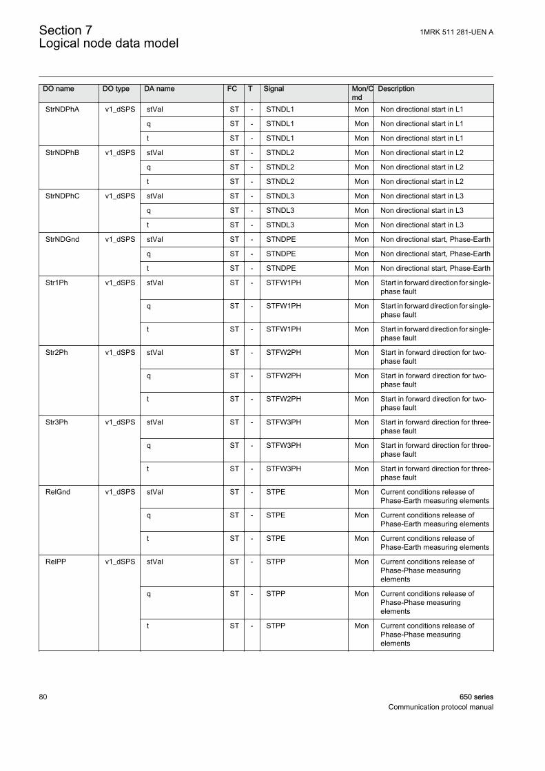
DO name DO type DA name FC T Signal Mon/Cmd
Description
StrNDPhA v1_dSPS stVal ST - STNDL1 Mon Non directional start in L1
q ST - STNDL1 Mon Non directional start in L1
t ST - STNDL1 Mon Non directional start in L1
StrNDPhB v1_dSPS stVal ST - STNDL2 Mon Non directional start in L2
q ST - STNDL2 Mon Non directional start in L2
t ST - STNDL2 Mon Non directional start in L2
StrNDPhC v1_dSPS stVal ST - STNDL3 Mon Non directional start in L3
q ST - STNDL3 Mon Non directional start in L3
t ST - STNDL3 Mon Non directional start in L3
StrNDGnd v1_dSPS stVal ST - STNDPE Mon Non directional start, Phase-Earth
q ST - STNDPE Mon Non directional start, Phase-Earth
t ST - STNDPE Mon Non directional start, Phase-Earth
Str1Ph v1_dSPS stVal ST - STFW1PH Mon Start in forward direction for single-phase fault
q ST - STFW1PH Mon Start in forward direction for single-phase fault
t ST - STFW1PH Mon Start in forward direction for single-phase fault
Str2Ph v1_dSPS stVal ST - STFW2PH Mon Start in forward direction for two-phase fault
q ST - STFW2PH Mon Start in forward direction for two-phase fault
t ST - STFW2PH Mon Start in forward direction for two-phase fault
Str3Ph v1_dSPS stVal ST - STFW3PH Mon Start in forward direction for three-phase fault
q ST - STFW3PH Mon Start in forward direction for three-phase fault
t ST - STFW3PH Mon Start in forward direction for three-phase fault
RelGnd v1_dSPS stVal ST - STPE Mon Current conditions release ofPhase-Earth measuring elements
q ST - STPE Mon Current conditions release ofPhase-Earth measuring elements
t ST - STPE Mon Current conditions release ofPhase-Earth measuring elements
RelPP v1_dSPS stVal ST - STPP Mon Current conditions release ofPhase-Phase measuringelements
q ST - STPP Mon Current conditions release ofPhase-Phase measuringelements
t ST - STPP Mon Current conditions release ofPhase-Phase measuringelements
Section 7 1MRK 511 281-UEN ALogical node data model
80 650 seriesCommunication protocol manual
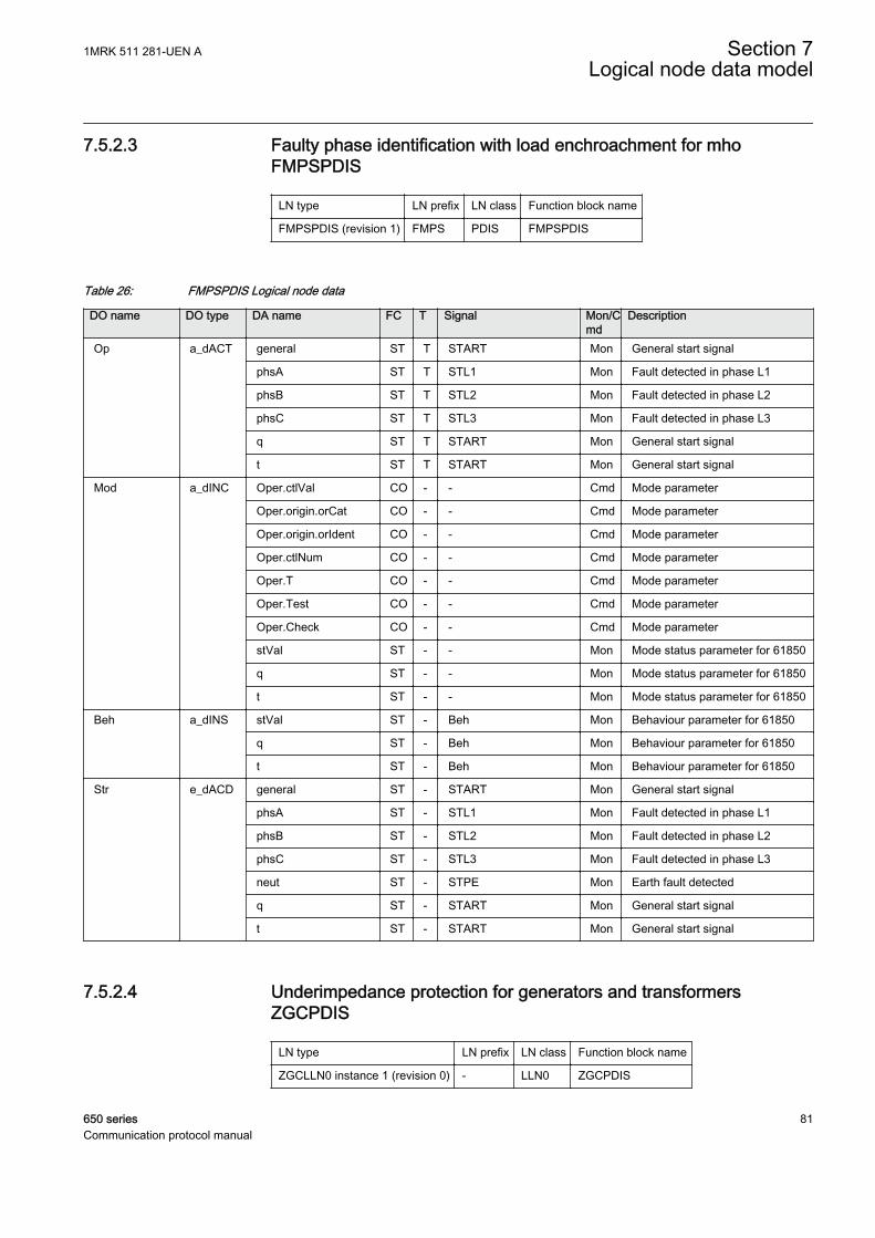
7.5.2.3 Faulty phase identification with load enchroachment for mhoFMPSPDIS
LN type LN prefix LN class Function block name
FMPSPDIS (revision 1) FMPS PDIS FMPSPDIS
Table 26: FMPSPDIS Logical node data
DO name DO type DA name FC T Signal Mon/Cmd
Description
Op a_dACT general ST T START Mon General start signal
phsA ST T STL1 Mon Fault detected in phase L1
phsB ST T STL2 Mon Fault detected in phase L2
phsC ST T STL3 Mon Fault detected in phase L3
q ST T START Mon General start signal
t ST T START Mon General start signal
Mod a_dINC Oper.ctlVal CO - - Cmd Mode parameter
Oper.origin.orCat CO - - Cmd Mode parameter
Oper.origin.orIdent CO - - Cmd Mode parameter
Oper.ctlNum CO - - Cmd Mode parameter
Oper.T CO - - Cmd Mode parameter
Oper.Test CO - - Cmd Mode parameter
Oper.Check CO - - Cmd Mode parameter
stVal ST - - Mon Mode status parameter for 61850
q ST - - Mon Mode status parameter for 61850
t ST - - Mon Mode status parameter for 61850
Beh a_dINS stVal ST - Beh Mon Behaviour parameter for 61850
q ST - Beh Mon Behaviour parameter for 61850
t ST - Beh Mon Behaviour parameter for 61850
Str e_dACD general ST - START Mon General start signal
phsA ST - STL1 Mon Fault detected in phase L1
phsB ST - STL2 Mon Fault detected in phase L2
phsC ST - STL3 Mon Fault detected in phase L3
neut ST - STPE Mon Earth fault detected
q ST - START Mon General start signal
t ST - START Mon General start signal
7.5.2.4 Underimpedance protection for generators and transformersZGCPDIS
LN type LN prefix LN class Function block name
ZGCLLN0 instance 1 (revision 0) - LLN0 ZGCPDIS
1MRK 511 281-UEN A Section 7Logical node data model
650 series 81Communication protocol manual
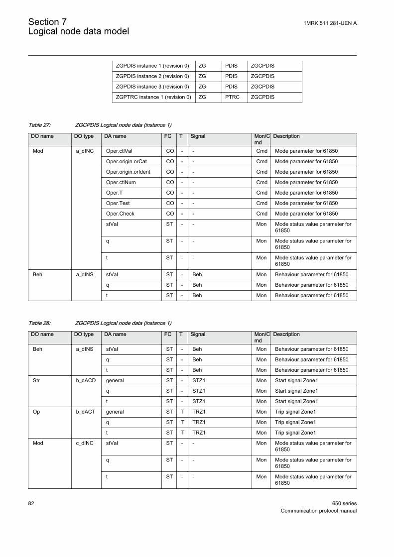
ZGPDIS instance 1 (revision 0) ZG PDIS ZGCPDIS
ZGPDIS instance 2 (revision 0) ZG PDIS ZGCPDIS
ZGPDIS instance 3 (revision 0) ZG PDIS ZGCPDIS
ZGPTRC instance 1 (revision 0) ZG PTRC ZGCPDIS
Table 27: ZGCPDIS Logical node data (instance 1)
DO name DO type DA name FC T Signal Mon/Cmd
Description
Mod a_dINC Oper.ctlVal CO - - Cmd Mode parameter for 61850
Oper.origin.orCat CO - - Cmd Mode parameter for 61850
Oper.origin.orIdent CO - - Cmd Mode parameter for 61850
Oper.ctlNum CO - - Cmd Mode parameter for 61850
Oper.T CO - - Cmd Mode parameter for 61850
Oper.Test CO - - Cmd Mode parameter for 61850
Oper.Check CO - - Cmd Mode parameter for 61850
stVal ST - - Mon Mode status value parameter for61850
q ST - - Mon Mode status value parameter for61850
t ST - - Mon Mode status value parameter for61850
Beh a_dINS stVal ST - Beh Mon Behaviour parameter for 61850
q ST - Beh Mon Behaviour parameter for 61850
t ST - Beh Mon Behaviour parameter for 61850
Table 28: ZGCPDIS Logical node data (instance 1)
DO name DO type DA name FC T Signal Mon/Cmd
Description
Beh a_dINS stVal ST - Beh Mon Behaviour parameter for 61850
q ST - Beh Mon Behaviour parameter for 61850
t ST - Beh Mon Behaviour parameter for 61850
Str b_dACD general ST - STZ1 Mon Start signal Zone1
q ST - STZ1 Mon Start signal Zone1
t ST - STZ1 Mon Start signal Zone1
Op b_dACT general ST T TRZ1 Mon Trip signal Zone1
q ST T TRZ1 Mon Trip signal Zone1
t ST T TRZ1 Mon Trip signal Zone1
Mod c_dINC stVal ST - - Mon Mode status value parameter for61850
q ST - - Mon Mode status value parameter for61850
t ST - - Mon Mode status value parameter for61850
Section 7 1MRK 511 281-UEN ALogical node data model
82 650 seriesCommunication protocol manual
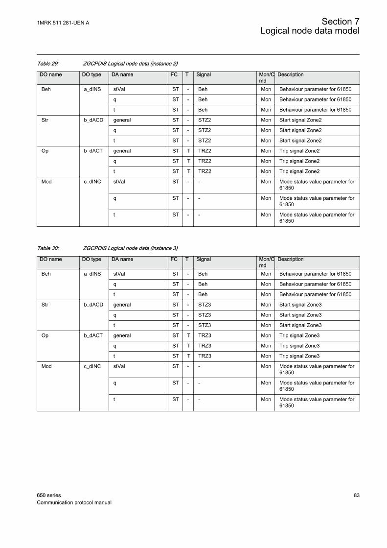
Table 29: ZGCPDIS Logical node data (instance 2)
DO name DO type DA name FC T Signal Mon/Cmd
Description
Beh a_dINS stVal ST - Beh Mon Behaviour parameter for 61850
q ST - Beh Mon Behaviour parameter for 61850
t ST - Beh Mon Behaviour parameter for 61850
Str b_dACD general ST - STZ2 Mon Start signal Zone2
q ST - STZ2 Mon Start signal Zone2
t ST - STZ2 Mon Start signal Zone2
Op b_dACT general ST T TRZ2 Mon Trip signal Zone2
q ST T TRZ2 Mon Trip signal Zone2
t ST T TRZ2 Mon Trip signal Zone2
Mod c_dINC stVal ST - - Mon Mode status value parameter for61850
q ST - - Mon Mode status value parameter for61850
t ST - - Mon Mode status value parameter for61850
Table 30: ZGCPDIS Logical node data (instance 3)
DO name DO type DA name FC T Signal Mon/Cmd
Description
Beh a_dINS stVal ST - Beh Mon Behaviour parameter for 61850
q ST - Beh Mon Behaviour parameter for 61850
t ST - Beh Mon Behaviour parameter for 61850
Str b_dACD general ST - STZ3 Mon Start signal Zone3
q ST - STZ3 Mon Start signal Zone3
t ST - STZ3 Mon Start signal Zone3
Op b_dACT general ST T TRZ3 Mon Trip signal Zone3
q ST T TRZ3 Mon Trip signal Zone3
t ST T TRZ3 Mon Trip signal Zone3
Mod c_dINC stVal ST - - Mon Mode status value parameter for61850
q ST - - Mon Mode status value parameter for61850
t ST - - Mon Mode status value parameter for61850
1MRK 511 281-UEN A Section 7Logical node data model
650 series 83Communication protocol manual
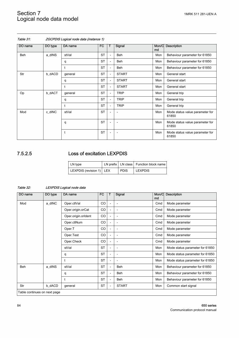
Table 31: ZGCPDIS Logical node data (instance 1)
DO name DO type DA name FC T Signal Mon/Cmd
Description
Beh a_dINS stVal ST - Beh Mon Behaviour parameter for 61850
q ST - Beh Mon Behaviour parameter for 61850
t ST - Beh Mon Behaviour parameter for 61850
Str b_dACD general ST - START Mon General start
q ST - START Mon General start
t ST - START Mon General start
Op b_dACT general ST - TRIP Mon General trip
q ST - TRIP Mon General trip
t ST - TRIP Mon General trip
Mod c_dINC stVal ST - - Mon Mode status value parameter for61850
q ST - - Mon Mode status value parameter for61850
t ST - - Mon Mode status value parameter for61850
7.5.2.5 Loss of excitation LEXPDIS
LN type LN prefix LN class Function block name
LEXPDIS (revision 1) LEX PDIS LEXPDIS
Table 32: LEXPDIS Logical node data
DO name DO type DA name FC T Signal Mon/Cmd
Description
Mod a_dINC Oper.ctlVal CO - - Cmd Mode parameter
Oper.origin.orCat CO - - Cmd Mode parameter
Oper.origin.orIdent CO - - Cmd Mode parameter
Oper.ctlNum CO - - Cmd Mode parameter
Oper.T CO - - Cmd Mode parameter
Oper.Test CO - - Cmd Mode parameter
Oper.Check CO - - Cmd Mode parameter
stVal ST - - Mon Mode status parameter for 61850
q ST - - Mon Mode status parameter for 61850
t ST - - Mon Mode status parameter for 61850
Beh a_dINS stVal ST - Beh Mon Behaviour parameter for 61850
q ST - Beh Mon Behaviour parameter for 61850
t ST - Beh Mon Behaviour parameter for 61850
Str b_dACD general ST - START Mon Common start signal
Table continues on next page
Section 7 1MRK 511 281-UEN ALogical node data model
84 650 seriesCommunication protocol manual

DO name DO type DA name FC T Signal Mon/Cmd
Description
Str b_dACD q ST - START Mon Common start signal
t ST - START Mon Common start signal
Op b_dACT general ST T TRIP Mon Common trip signal
q ST T TRIP Mon Common trip signal
t ST T TRIP Mon Common trip signal
OpZ1 v1_dSPS stVal ST - TRZ1 Mon Trip signal from impedance zoneZ1
q ST - TRZ1 Mon Trip signal from impedance zoneZ1
t ST - TRZ1 Mon Trip signal from impedance zoneZ1
OpZ2 v1_dSPS stVal ST - TRZ2 Mon Trip signal from impedance zoneZ2
q ST - TRZ2 Mon Trip signal from impedance zoneZ2
t ST - TRZ2 Mon Trip signal from impedance zoneZ2
StrZ1 v1_dSPS stVal ST - STZ1 Mon Start signal from impedance zoneZ1
q ST - STZ1 Mon Start signal from impedance zoneZ1
t ST - STZ1 Mon Start signal from impedance zoneZ1
StrZ2 v1_dSPS stVal ST - STZ2 Mon Start signal from impedance zoneZ2
q ST - STZ2 Mon Start signal from impedance zoneZ2
t ST - STZ2 Mon Start signal from impedance zoneZ2
PriRis v2_dMV mag.f MX - ROHM Mon Resistance in Primary Ohms
q MX - ROHM Mon Resistance in Primary Ohms
t MX - ROHM Mon Resistance in Primary Ohms
PriReact v2_dMV mag.f MX - XOHM Mon Reactance in Primary Ohms
q MX - XOHM Mon Reactance in Primary Ohms
t MX - XOHM Mon Reactance in Primary Ohms
7.5.2.6 Load enchroachment LEPDIS
LN type LN prefix LN class Function block name
LEPDIS (revision 0) LE PDIS LEPDIS
1MRK 511 281-UEN A Section 7Logical node data model
650 series 85Communication protocol manual
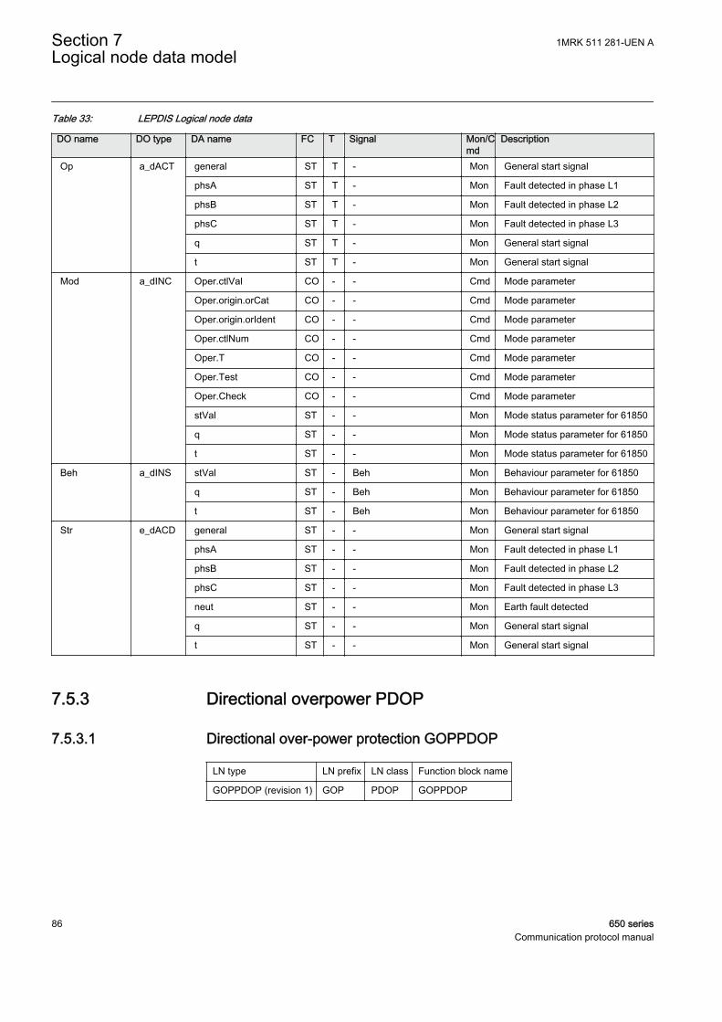
Table 33: LEPDIS Logical node data
DO name DO type DA name FC T Signal Mon/Cmd
Description
Op a_dACT general ST T - Mon General start signal
phsA ST T - Mon Fault detected in phase L1
phsB ST T - Mon Fault detected in phase L2
phsC ST T - Mon Fault detected in phase L3
q ST T - Mon General start signal
t ST T - Mon General start signal
Mod a_dINC Oper.ctlVal CO - - Cmd Mode parameter
Oper.origin.orCat CO - - Cmd Mode parameter
Oper.origin.orIdent CO - - Cmd Mode parameter
Oper.ctlNum CO - - Cmd Mode parameter
Oper.T CO - - Cmd Mode parameter
Oper.Test CO - - Cmd Mode parameter
Oper.Check CO - - Cmd Mode parameter
stVal ST - - Mon Mode status parameter for 61850
q ST - - Mon Mode status parameter for 61850
t ST - - Mon Mode status parameter for 61850
Beh a_dINS stVal ST - Beh Mon Behaviour parameter for 61850
q ST - Beh Mon Behaviour parameter for 61850
t ST - Beh Mon Behaviour parameter for 61850
Str e_dACD general ST - - Mon General start signal
phsA ST - - Mon Fault detected in phase L1
phsB ST - - Mon Fault detected in phase L2
phsC ST - - Mon Fault detected in phase L3
neut ST - - Mon Earth fault detected
q ST - - Mon General start signal
t ST - - Mon General start signal
7.5.3 Directional overpower PDOP
7.5.3.1 Directional over-power protection GOPPDOP
LN type LN prefix LN class Function block name
GOPPDOP (revision 1) GOP PDOP GOPPDOP
Section 7 1MRK 511 281-UEN ALogical node data model
86 650 seriesCommunication protocol manual
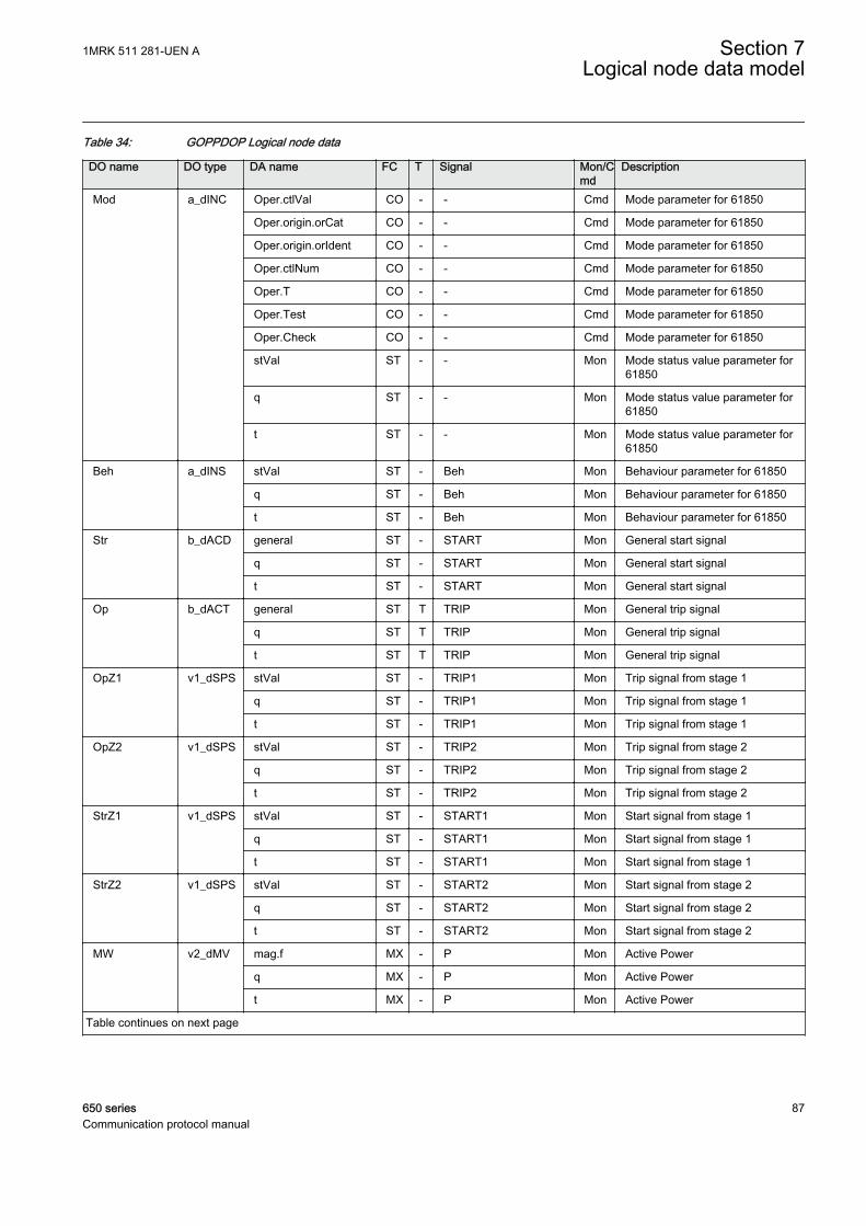
Table 34: GOPPDOP Logical node data
DO name DO type DA name FC T Signal Mon/Cmd
Description
Mod a_dINC Oper.ctlVal CO - - Cmd Mode parameter for 61850
Oper.origin.orCat CO - - Cmd Mode parameter for 61850
Oper.origin.orIdent CO - - Cmd Mode parameter for 61850
Oper.ctlNum CO - - Cmd Mode parameter for 61850
Oper.T CO - - Cmd Mode parameter for 61850
Oper.Test CO - - Cmd Mode parameter for 61850
Oper.Check CO - - Cmd Mode parameter for 61850
stVal ST - - Mon Mode status value parameter for61850
q ST - - Mon Mode status value parameter for61850
t ST - - Mon Mode status value parameter for61850
Beh a_dINS stVal ST - Beh Mon Behaviour parameter for 61850
q ST - Beh Mon Behaviour parameter for 61850
t ST - Beh Mon Behaviour parameter for 61850
Str b_dACD general ST - START Mon General start signal
q ST - START Mon General start signal
t ST - START Mon General start signal
Op b_dACT general ST T TRIP Mon General trip signal
q ST T TRIP Mon General trip signal
t ST T TRIP Mon General trip signal
OpZ1 v1_dSPS stVal ST - TRIP1 Mon Trip signal from stage 1
q ST - TRIP1 Mon Trip signal from stage 1
t ST - TRIP1 Mon Trip signal from stage 1
OpZ2 v1_dSPS stVal ST - TRIP2 Mon Trip signal from stage 2
q ST - TRIP2 Mon Trip signal from stage 2
t ST - TRIP2 Mon Trip signal from stage 2
StrZ1 v1_dSPS stVal ST - START1 Mon Start signal from stage 1
q ST - START1 Mon Start signal from stage 1
t ST - START1 Mon Start signal from stage 1
StrZ2 v1_dSPS stVal ST - START2 Mon Start signal from stage 2
q ST - START2 Mon Start signal from stage 2
t ST - START2 Mon Start signal from stage 2
MW v2_dMV mag.f MX - P Mon Active Power
q MX - P Mon Active Power
t MX - P Mon Active Power
Table continues on next page
1MRK 511 281-UEN A Section 7Logical node data model
650 series 87Communication protocol manual

DO name DO type DA name FC T Signal Mon/Cmd
Description
MVAr v2_dMV mag.f MX - Q Mon Reactive power
q MX - Q Mon Reactive power
t MX - Q Mon Reactive power
7.5.4 Directional underpower PDUP
LN type LN prefix LN class Function block name
GUPPDUP (revision 1) GUP PDUP GUPPDUP
Table 35: GUPPDUP Logical node data
DO name DO type DA name FC T Signal Mon/Cmd
Description
Mod a_dINC Oper.ctlVal CO - - Cmd Mode parameter for 61850
Oper.origin.orCat CO - - Cmd Mode parameter for 61850
Oper.origin.orIdent CO - - Cmd Mode parameter for 61850
Oper.ctlNum CO - - Cmd Mode parameter for 61850
Oper.T CO - - Cmd Mode parameter for 61850
Oper.Test CO - - Cmd Mode parameter for 61850
Oper.Check CO - - Cmd Mode parameter for 61850
stVal ST - - Mon Mode status value parameter for61850
q ST - - Mon Mode status value parameter for61850
t ST - - Mon Mode status value parameter for61850
Beh a_dINS stVal ST - Beh Mon Behaviour parameter for 61850
q ST - Beh Mon Behaviour parameter for 61850
t ST - Beh Mon Behaviour parameter for 61850
Str b_dACD general ST - START Mon General start signal
q ST - START Mon General start signal
t ST - START Mon General start signal
Op b_dACT general ST T TRIP Mon General trip signal
q ST T TRIP Mon General trip signal
t ST T TRIP Mon General trip signal
OpZ1 v1_dSPS stVal ST - TRIP1 Mon Trip signal from stage 1
q ST - TRIP1 Mon Trip signal from stage 1
t ST - TRIP1 Mon Trip signal from stage 1
OpZ2 v1_dSPS stVal ST - TRIP2 Mon Trip signal from stage 2
q ST - TRIP2 Mon Trip signal from stage 2
Table continues on next page
Section 7 1MRK 511 281-UEN ALogical node data model
88 650 seriesCommunication protocol manual

DO name DO type DA name FC T Signal Mon/Cmd
Description
OpZ2 v1_dSPS t ST - TRIP2 Mon Trip signal from stage 2
StrZ1 v1_dSPS stVal ST - START1 Mon Start signal from stage 1
q ST - START1 Mon Start signal from stage 1
t ST - START1 Mon Start signal from stage 1
StrZ2 v1_dSPS stVal ST - START2 Mon Start signal from stage 2
q ST - START2 Mon Start signal from stage 2
t ST - START2 Mon Start signal from stage 2
MW v2_dMV mag.f MX - P Mon Active Power
q MX - P Mon Active Power
t MX - P Mon Active Power
MVAr v2_dMV mag.f MX - Q Mon Reactive power
q MX - Q Mon Reactive power
t MX - Q Mon Reactive power
7.5.5 Rate of change of frequency PFRC
7.5.5.1 Rate-of-change frequency protection SAPFRC
LN type LN prefix LN class Function block name
SAPFRC (revision 1) SA PFRC SAPFRC
Table 36: SAPFRC Logical node data
DO name DO type DA name FC T Signal Mon/Cmd
Description
Mod a_dINC Oper.ctlVal CO - - Cmd Mode parameter
Oper.origin.orCat CO - - Cmd Mode parameter
Oper.origin.orIdent CO - - Cmd Mode parameter
Oper.ctlNum CO - - Cmd Mode parameter
Oper.T CO - - Cmd Mode parameter
Oper.Test CO - - Cmd Mode parameter
Oper.Check CO - - Cmd Mode parameter
stVal ST - - Mon Mode status parameter for 61850
q ST - - Mon Mode status parameter for 61850
t ST - - Mon Mode status parameter for 61850
Beh a_dINS stVal ST - Beh Mon Behaviour parameter for 61850
q ST - Beh Mon Behaviour parameter for 61850
t ST - Beh Mon Behaviour parameter for 61850
Table continues on next page
1MRK 511 281-UEN A Section 7Logical node data model
650 series 89Communication protocol manual
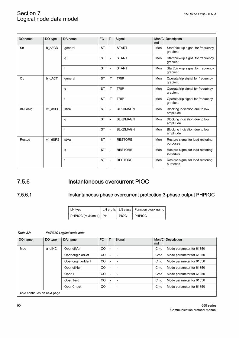
DO name DO type DA name FC T Signal Mon/Cmd
Description
Str b_dACD general ST - START Mon Start/pick-up signal for frequencygradient
q ST - START Mon Start/pick-up signal for frequencygradient
t ST - START Mon Start/pick-up signal for frequencygradient
Op b_dACT general ST T TRIP Mon Operate/trip signal for frequencygradient
q ST T TRIP Mon Operate/trip signal for frequencygradient
t ST T TRIP Mon Operate/trip signal for frequencygradient
BlkLoMg v1_dSPS stVal ST - BLKDMAGN Mon Blocking indication due to lowamplitude
q ST - BLKDMAGN Mon Blocking indication due to lowamplitude
t ST - BLKDMAGN Mon Blocking indication due to lowamplitude
RestLd v1_dSPS stVal ST - RESTORE Mon Restore signal for load restoringpurposes
q ST - RESTORE Mon Restore signal for load restoringpurposes
t ST - RESTORE Mon Restore signal for load restoringpurposes
7.5.6 Instantaneous overcurrent PIOC
7.5.6.1 Instantaneous phase overcurrent protection 3-phase output PHPIOC
LN type LN prefix LN class Function block name
PHPIOC (revision 1) PH PIOC PHPIOC
Table 37: PHPIOC Logical node data
DO name DO type DA name FC T Signal Mon/Cmd
Description
Mod a_dINC Oper.ctlVal CO - - Cmd Mode parameter for 61850
Oper.origin.orCat CO - - Cmd Mode parameter for 61850
Oper.origin.orIdent CO - - Cmd Mode parameter for 61850
Oper.ctlNum CO - - Cmd Mode parameter for 61850
Oper.T CO - - Cmd Mode parameter for 61850
Oper.Test CO - - Cmd Mode parameter for 61850
Oper.Check CO - - Cmd Mode parameter for 61850
Table continues on next page
Section 7 1MRK 511 281-UEN ALogical node data model
90 650 seriesCommunication protocol manual
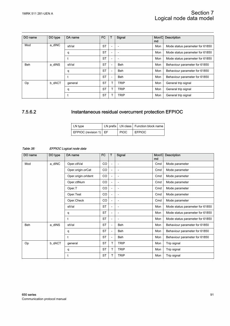
DO name DO type DA name FC T Signal Mon/Cmd
Description
Mod a_dINC stVal ST - - Mon Mode status parameter for 61850
q ST - - Mon Mode status parameter for 61850
t ST - - Mon Mode status parameter for 61850
Beh a_dINS stVal ST - Beh Mon Behaviour parameter for 61850
q ST - Beh Mon Behaviour parameter for 61850
t ST - Beh Mon Behaviour parameter for 61850
Op b_dACT general ST T TRIP Mon General trip signal
q ST T TRIP Mon General trip signal
t ST T TRIP Mon General trip signal
7.5.6.2 Instantaneous residual overcurrent protection EFPIOC
LN type LN prefix LN class Function block name
EFPIOC (revision 1) EF PIOC EFPIOC
Table 38: EFPIOC Logical node data
DO name DO type DA name FC T Signal Mon/Cmd
Description
Mod a_dINC Oper.ctlVal CO - - Cmd Mode parameter
Oper.origin.orCat CO - - Cmd Mode parameter
Oper.origin.orIdent CO - - Cmd Mode parameter
Oper.ctlNum CO - - Cmd Mode parameter
Oper.T CO - - Cmd Mode parameter
Oper.Test CO - - Cmd Mode parameter
Oper.Check CO - - Cmd Mode parameter
stVal ST - - Mon Mode status parameter for 61850
q ST - - Mon Mode status parameter for 61850
t ST - - Mon Mode status parameter for 61850
Beh a_dINS stVal ST - Beh Mon Behaviour parameter for 61850
q ST - Beh Mon Behaviour parameter for 61850
t ST - Beh Mon Behaviour parameter for 61850
Op b_dACT general ST T TRIP Mon Trip signal
q ST T TRIP Mon Trip signal
t ST T TRIP Mon Trip signal
1MRK 511 281-UEN A Section 7Logical node data model
650 series 91Communication protocol manual

7.5.7 Local acceleration logic PLAL
7.5.7.1 Local acceleration logic ZCLCPLAL
LN type LN prefix LN class Function block name
ZCLCPLAL (revision 1) ZCLC PLAL ZCLCPLAL
Table 39: ZCLCPLAL Logical node data
DO name DO type DA name FC T Signal Mon/Cmd
Description
Mod a_dINC Oper.ctlVal CO - - Cmd Mode parameter
Oper.origin.orCat CO - - Cmd Mode parameter
Oper.origin.orIdent CO - - Cmd Mode parameter
Oper.ctlNum CO - - Cmd Mode parameter
Oper.T CO - - Cmd Mode parameter
Oper.Test CO - - Cmd Mode parameter
Oper.Check CO - - Cmd Mode parameter
stVal ST - - Mon Mode status parameter for 61850
q ST - - Mon Mode status parameter for 61850
t ST - - Mon Mode status parameter for 61850
Beh a_dINS stVal ST - Beh Mon Behaviour parameter for 61850
q ST - Beh Mon Behaviour parameter for 61850
t ST - Beh Mon Behaviour parameter for 61850
OpLosLod v2_dACT general ST - TRLL Mon Trip by loss of load
q ST - TRLL Mon Trip by loss of load
t ST - TRLL Mon Trip by loss of load
OpZnExd v2_dACT general ST - TRZE Mon Trip by zone extension
q ST - TRZE Mon Trip by zone extension
t ST - TRZE Mon Trip by zone extension
7.5.8 Protection scheme PSCH
7.5.8.1 Scheme communication logic with delta based blocking scheme signaltransmit ZCPSCH
LN type LN prefix LN class Function block name
ZCPSCH (revision 2) ZC PSCH ZCPSCH
Section 7 1MRK 511 281-UEN ALogical node data model
92 650 seriesCommunication protocol manual

Table 40: ZCPSCH Logical node data
DO name DO type DA name FC T Signal Mon/Cmd
Description
Mod a_dINC Oper.ctlVal CO - - Cmd Mode parameter
Oper.origin.orCat CO - - Cmd Mode parameter
Oper.origin.orIdent CO - - Cmd Mode parameter
Oper.ctlNum CO - - Cmd Mode parameter
Oper.T CO - - Cmd Mode parameter
Oper.Test CO - - Cmd Mode parameter
Oper.Check CO - - Cmd Mode parameter
stVal ST - - Mon Mode status parameter for 61850
q ST - - Mon Mode status parameter for 61850
t ST - - Mon Mode status parameter for 61850
Beh a_dINS stVal ST - Beh Mon Behaviour parameter for 61850
q ST - Beh Mon Behaviour parameter for 61850
t ST - Beh Mon Behaviour parameter for 61850
LosOfGrd a_dSPS stVal ST - LCG Mon Loss of carrier guard signal
q ST - LCG Mon Loss of carrier guard signal
t ST - LCG Mon Loss of carrier guard signal
ProRx a_dSPS stVal ST T - Mon Carrier signal received or missingcarrier guard signal
q ST T - Mon Carrier signal received or missingcarrier guard signal
t ST T - Mon Carrier signal received or missingcarrier guard signal
ProTx a_dSPS stVal ST T - Mon Teleprotection signal transmittedfor a forward fault
q ST T - Mon Teleprotection signal transmittedfor a forward fault
t ST T - Mon Teleprotection signal transmittedfor a forward fault
Str b_dACD general ST - CS Mon Carrier Send signal
dirGeneral ST - - Mon Directional attribute of carrier sendsignal
q ST - CS Mon Carrier Send signal
t ST - CS Mon Carrier Send signal
CarRx b_dACT general ST - CRL Mon Carrier signal received or missingcarrier guard signal
q ST - CRL Mon Carrier signal received or missingcarrier guard signal
t ST - CRL Mon Carrier signal received or missingcarrier guard signal
Op b_dACT general ST T TRIP Mon Trip output
q ST T TRIP Mon Trip output
t ST T TRIP Mon Trip output
Table continues on next page
1MRK 511 281-UEN A Section 7Logical node data model
650 series 93Communication protocol manual
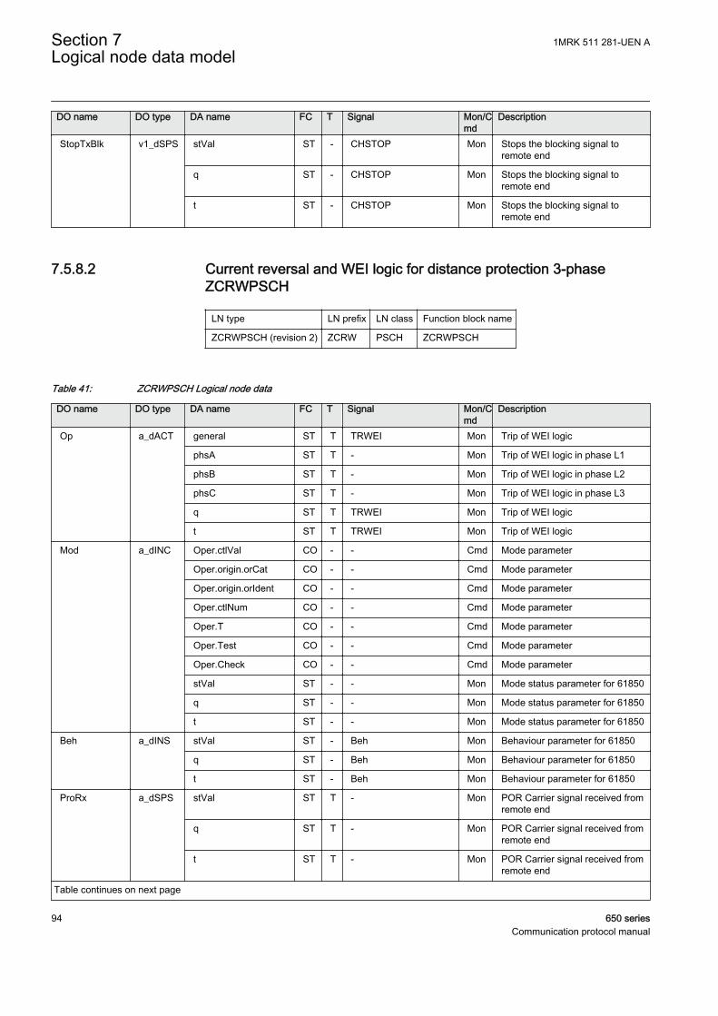
DO name DO type DA name FC T Signal Mon/Cmd
Description
StopTxBlk v1_dSPS stVal ST - CHSTOP Mon Stops the blocking signal toremote end
q ST - CHSTOP Mon Stops the blocking signal toremote end
t ST - CHSTOP Mon Stops the blocking signal toremote end
7.5.8.2 Current reversal and WEI logic for distance protection 3-phaseZCRWPSCH
LN type LN prefix LN class Function block name
ZCRWPSCH (revision 2) ZCRW PSCH ZCRWPSCH
Table 41: ZCRWPSCH Logical node data
DO name DO type DA name FC T Signal Mon/Cmd
Description
Op a_dACT general ST T TRWEI Mon Trip of WEI logic
phsA ST T - Mon Trip of WEI logic in phase L1
phsB ST T - Mon Trip of WEI logic in phase L2
phsC ST T - Mon Trip of WEI logic in phase L3
q ST T TRWEI Mon Trip of WEI logic
t ST T TRWEI Mon Trip of WEI logic
Mod a_dINC Oper.ctlVal CO - - Cmd Mode parameter
Oper.origin.orCat CO - - Cmd Mode parameter
Oper.origin.orIdent CO - - Cmd Mode parameter
Oper.ctlNum CO - - Cmd Mode parameter
Oper.T CO - - Cmd Mode parameter
Oper.Test CO - - Cmd Mode parameter
Oper.Check CO - - Cmd Mode parameter
stVal ST - - Mon Mode status parameter for 61850
q ST - - Mon Mode status parameter for 61850
t ST - - Mon Mode status parameter for 61850
Beh a_dINS stVal ST - Beh Mon Behaviour parameter for 61850
q ST - Beh Mon Behaviour parameter for 61850
t ST - Beh Mon Behaviour parameter for 61850
ProRx a_dSPS stVal ST T - Mon POR Carrier signal received fromremote end
q ST T - Mon POR Carrier signal received fromremote end
t ST T - Mon POR Carrier signal received fromremote end
Table continues on next page
Section 7 1MRK 511 281-UEN ALogical node data model
94 650 seriesCommunication protocol manual
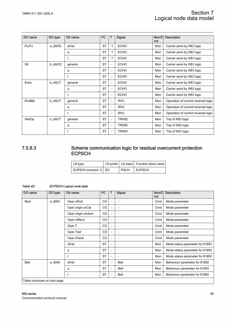
DO name DO type DA name FC T Signal Mon/Cmd
Description
ProTx a_dSPS stVal ST T ECHO Mon Carrier send by WEI logic
q ST T ECHO Mon Carrier send by WEI logic
t ST T ECHO Mon Carrier send by WEI logic
Str b_dACD general ST - ECHO Mon Carrier send by WEI logic
q ST - ECHO Mon Carrier send by WEI logic
t ST - ECHO Mon Carrier send by WEI logic
Echo b_dACT general ST - ECHO Mon Carrier send by WEI logic
q ST - ECHO Mon Carrier send by WEI logic
t ST - ECHO Mon Carrier send by WEI logic
RvABlk b_dACT general ST - IRVL Mon Operation of current reversal logic
q ST - IRVL Mon Operation of current reversal logic
t ST - IRVL Mon Operation of current reversal logic
WeiOp b_dACT general ST - TRWEI Mon Trip of WEI logic
q ST - TRWEI Mon Trip of WEI logic
t ST - TRWEI Mon Trip of WEI logic
7.5.8.3 Scheme communication logic for residual overcurrent protectionECPSCH
LN type LN prefix LN class Function block name
ECPSCH (revision 1) EC PSCH ECPSCH
Table 42: ECPSCH Logical node data
DO name DO type DA name FC T Signal Mon/Cmd
Description
Mod a_dINC Oper.ctlVal CO - - Cmd Mode parameter
Oper.origin.orCat CO - - Cmd Mode parameter
Oper.origin.orIdent CO - - Cmd Mode parameter
Oper.ctlNum CO - - Cmd Mode parameter
Oper.T CO - - Cmd Mode parameter
Oper.Test CO - - Cmd Mode parameter
Oper.Check CO - - Cmd Mode parameter
stVal ST - - Mon Mode status parameter for 61850
q ST - - Mon Mode status parameter for 61850
t ST - - Mon Mode status parameter for 61850
Beh a_dINS stVal ST - Beh Mon Behaviour parameter for 61850
q ST - Beh Mon Behaviour parameter for 61850
t ST - Beh Mon Behaviour parameter for 61850
Table continues on next page
1MRK 511 281-UEN A Section 7Logical node data model
650 series 95Communication protocol manual
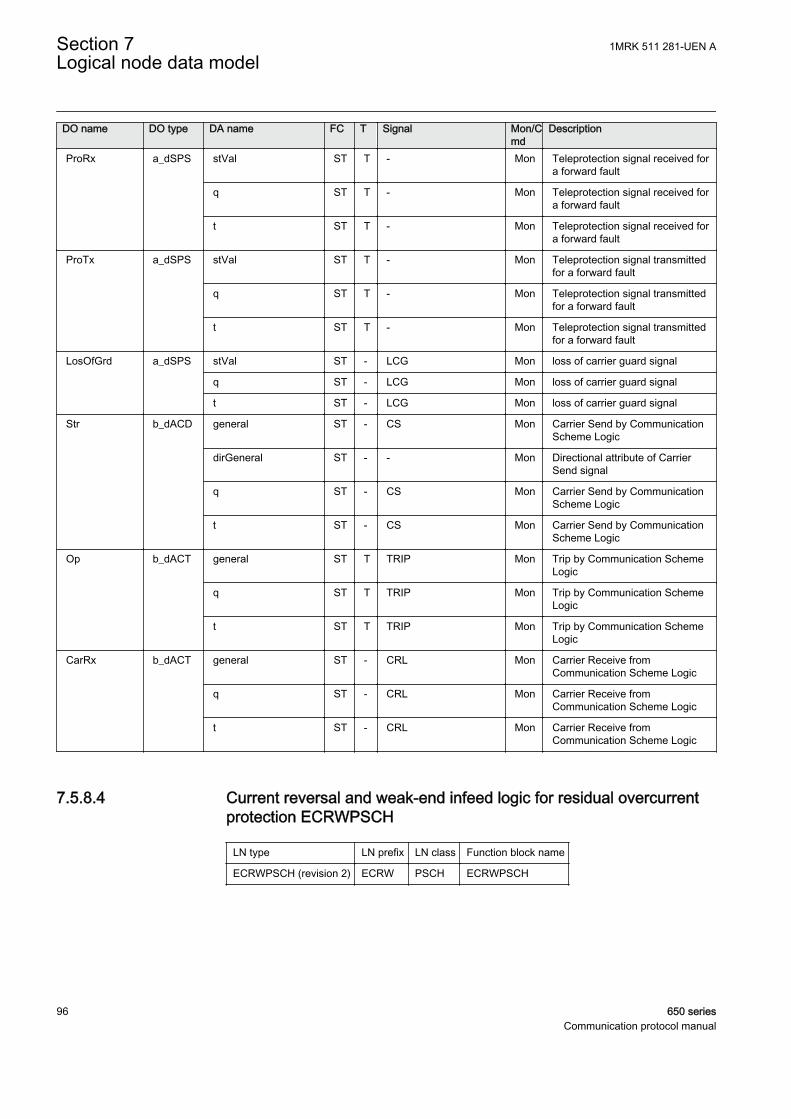
DO name DO type DA name FC T Signal Mon/Cmd
Description
ProRx a_dSPS stVal ST T - Mon Teleprotection signal received fora forward fault
q ST T - Mon Teleprotection signal received fora forward fault
t ST T - Mon Teleprotection signal received fora forward fault
ProTx a_dSPS stVal ST T - Mon Teleprotection signal transmittedfor a forward fault
q ST T - Mon Teleprotection signal transmittedfor a forward fault
t ST T - Mon Teleprotection signal transmittedfor a forward fault
LosOfGrd a_dSPS stVal ST - LCG Mon loss of carrier guard signal
q ST - LCG Mon loss of carrier guard signal
t ST - LCG Mon loss of carrier guard signal
Str b_dACD general ST - CS Mon Carrier Send by CommunicationScheme Logic
dirGeneral ST - - Mon Directional attribute of CarrierSend signal
q ST - CS Mon Carrier Send by CommunicationScheme Logic
t ST - CS Mon Carrier Send by CommunicationScheme Logic
Op b_dACT general ST T TRIP Mon Trip by Communication SchemeLogic
q ST T TRIP Mon Trip by Communication SchemeLogic
t ST T TRIP Mon Trip by Communication SchemeLogic
CarRx b_dACT general ST - CRL Mon Carrier Receive fromCommunication Scheme Logic
q ST - CRL Mon Carrier Receive fromCommunication Scheme Logic
t ST - CRL Mon Carrier Receive fromCommunication Scheme Logic
7.5.8.4 Current reversal and weak-end infeed logic for residual overcurrentprotection ECRWPSCH
LN type LN prefix LN class Function block name
ECRWPSCH (revision 2) ECRW PSCH ECRWPSCH
Section 7 1MRK 511 281-UEN ALogical node data model
96 650 seriesCommunication protocol manual

Table 43: ECRWPSCH Logical node data
DO name DO type DA name FC T Signal Mon/Cmd
Description
Mod a_dINC Oper.ctlVal CO - - Cmd Mode parameter
Oper.origin.orCat CO - - Cmd Mode parameter
Oper.origin.orIdent CO - - Cmd Mode parameter
Oper.ctlNum CO - - Cmd Mode parameter
Oper.T CO - - Cmd Mode parameter
Oper.Test CO - - Cmd Mode parameter
Oper.Check CO - - Cmd Mode parameter
stVal ST - - Mon Mode status parameter for 61850
q ST - - Mon Mode status parameter for 61850
t ST - - Mon Mode status parameter for 61850
Beh a_dINS stVal ST - Beh Mon Behaviour parameter for 61850
q ST - Beh Mon Behaviour parameter for 61850
t ST - Beh Mon Behaviour parameter for 61850
ProRx a_dSPS stVal ST T CR Mon POR Carrier signal received fromremote end
q ST T CR Mon POR Carrier signal received fromremote end
t ST T CR Mon POR Carrier signal received fromremote end
ProTx a_dSPS stVal ST T ECHO Mon Carrier send by WEI logic
q ST T ECHO Mon Carrier send by WEI logic
t ST T ECHO Mon Carrier send by WEI logic
Str b_dACD general ST - ECHO Mon Carrier send by WEI logic
q ST - ECHO Mon Carrier send by WEI logic
t ST - ECHO Mon Carrier send by WEI logic
Op b_dACT general ST T TRWEI Mon Trip of WEI logic
q ST T TRWEI Mon Trip of WEI logic
t ST T TRWEI Mon Trip of WEI logic
RvABlk b_dACT general ST - IRVL Mon Operation of current reversal logic
q ST - IRVL Mon Operation of current reversal logic
t ST - IRVL Mon Operation of current reversal logic
Echo b_dACT general ST - ECHO Mon Carrier send by WEI logic
q ST - ECHO Mon Carrier send by WEI logic
t ST - ECHO Mon Carrier send by WEI logic
WeiOp b_dACT general ST - TRWEI Mon Trip of WEI logic
q ST - TRWEI Mon Trip of WEI logic
t ST - TRWEI Mon Trip of WEI logic
1MRK 511 281-UEN A Section 7Logical node data model
650 series 97Communication protocol manual

7.5.9 Sensitive directional earth fault PSDE
7.5.9.1 Sensitive directional residual overcurrent and power protectionSDEPSDE
LN type LN prefix LN class Function block name
SDEPSDE (revision 1) SDE PSDE SDEPSDE
Table 44: SDEPSDE Logical node data
DO name DO type DA name FC T Signal Mon/Cmd
Description
Mod a_dINC Oper.ctlVal CO - - Cmd Mode parameter for 61850
Oper.origin.orCat CO - - Cmd Mode parameter for 61850
Oper.origin.orIdent CO - - Cmd Mode parameter for 61850
Oper.ctlNum CO - - Cmd Mode parameter for 61850
Oper.T CO - - Cmd Mode parameter for 61850
Oper.Test CO - - Cmd Mode parameter for 61850
Oper.Check CO - - Cmd Mode parameter for 61850
stVal ST - - Mon Mode status parameter for 61850
q ST - - Mon Mode status parameter for 61850
t ST - - Mon Mode status parameter for 61850
Beh a_dINS stVal ST - Beh Mon Behaviour parameter for 61850
q ST - Beh Mon Behaviour parameter for 61850
t ST - Beh Mon Behaviour parameter for 61850
Str b_dACD general ST - START Mon General start signal
dirGeneral ST - STDIR Mon Direction of fault
q ST - START Mon General start signal
t ST - START Mon General start signal
Op b_dACT general ST T TRIP Mon General trip signal
q ST T TRIP Mon General trip signal
t ST T TRIP Mon General trip signal
OpResA v1_dSPS stVal ST - TRNDIN Mon Trip of non-directional residualovercurrent
q ST - TRNDIN Mon Trip of non-directional residualovercurrent
t ST - TRNDIN Mon Trip of non-directional residualovercurrent
OpResV v1_dSPS stVal ST - TRUN Mon Trip of non-directional residualovervoltage
q ST - TRUN Mon Trip of non-directional residualovervoltage
Table continues on next page
Section 7 1MRK 511 281-UEN ALogical node data model
98 650 seriesCommunication protocol manual
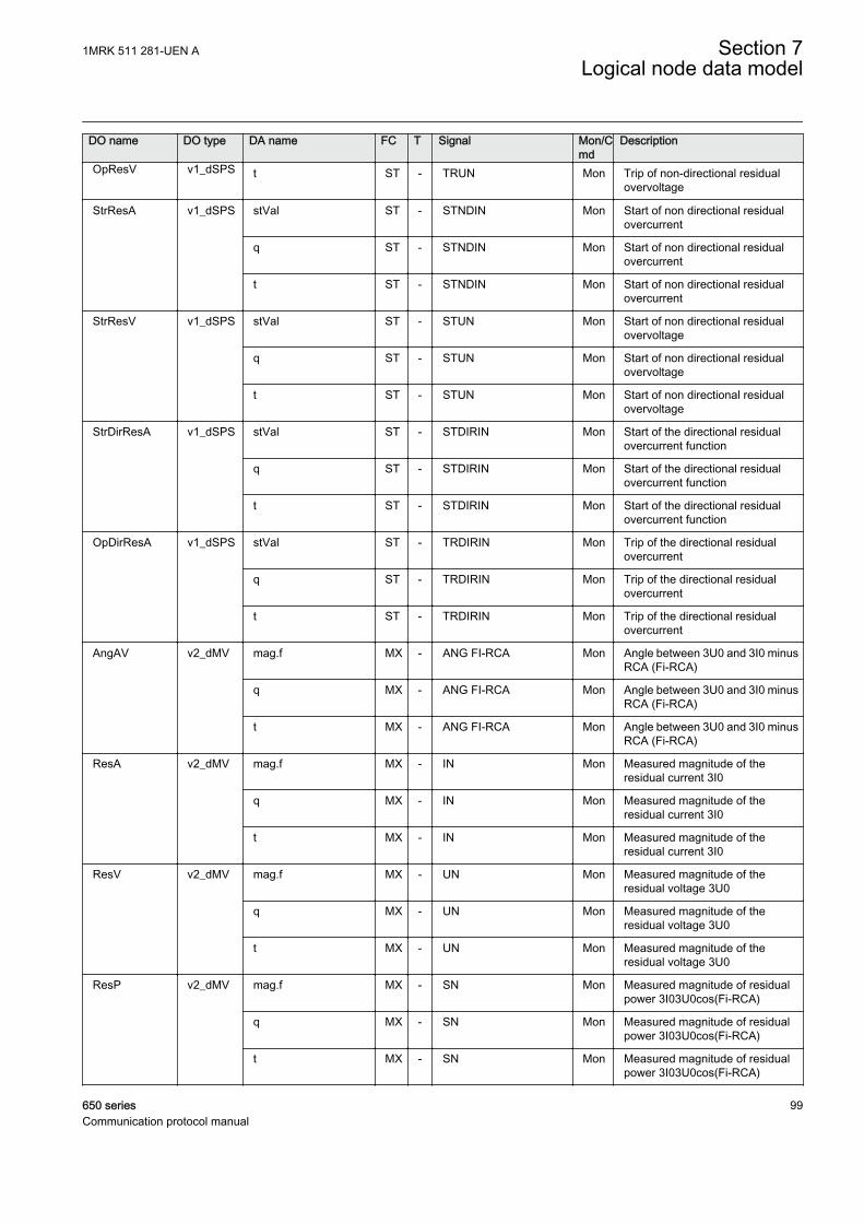
DO name DO type DA name FC T Signal Mon/Cmd
Description
OpResV v1_dSPS t ST - TRUN Mon Trip of non-directional residualovervoltage
StrResA v1_dSPS stVal ST - STNDIN Mon Start of non directional residualovercurrent
q ST - STNDIN Mon Start of non directional residualovercurrent
t ST - STNDIN Mon Start of non directional residualovercurrent
StrResV v1_dSPS stVal ST - STUN Mon Start of non directional residualovervoltage
q ST - STUN Mon Start of non directional residualovervoltage
t ST - STUN Mon Start of non directional residualovervoltage
StrDirResA v1_dSPS stVal ST - STDIRIN Mon Start of the directional residualovercurrent function
q ST - STDIRIN Mon Start of the directional residualovercurrent function
t ST - STDIRIN Mon Start of the directional residualovercurrent function
OpDirResA v1_dSPS stVal ST - TRDIRIN Mon Trip of the directional residualovercurrent
q ST - TRDIRIN Mon Trip of the directional residualovercurrent
t ST - TRDIRIN Mon Trip of the directional residualovercurrent
AngAV v2_dMV mag.f MX - ANG FI-RCA Mon Angle between 3U0 and 3I0 minusRCA (Fi-RCA)
q MX - ANG FI-RCA Mon Angle between 3U0 and 3I0 minusRCA (Fi-RCA)
t MX - ANG FI-RCA Mon Angle between 3U0 and 3I0 minusRCA (Fi-RCA)
ResA v2_dMV mag.f MX - IN Mon Measured magnitude of theresidual current 3I0
q MX - IN Mon Measured magnitude of theresidual current 3I0
t MX - IN Mon Measured magnitude of theresidual current 3I0
ResV v2_dMV mag.f MX - UN Mon Measured magnitude of theresidual voltage 3U0
q MX - UN Mon Measured magnitude of theresidual voltage 3U0
t MX - UN Mon Measured magnitude of theresidual voltage 3U0
ResP v2_dMV mag.f MX - SN Mon Measured magnitude of residualpower 3I03U0cos(Fi-RCA)
q MX - SN Mon Measured magnitude of residualpower 3I03U0cos(Fi-RCA)
t MX - SN Mon Measured magnitude of residualpower 3I03U0cos(Fi-RCA)
1MRK 511 281-UEN A Section 7Logical node data model
650 series 99Communication protocol manual
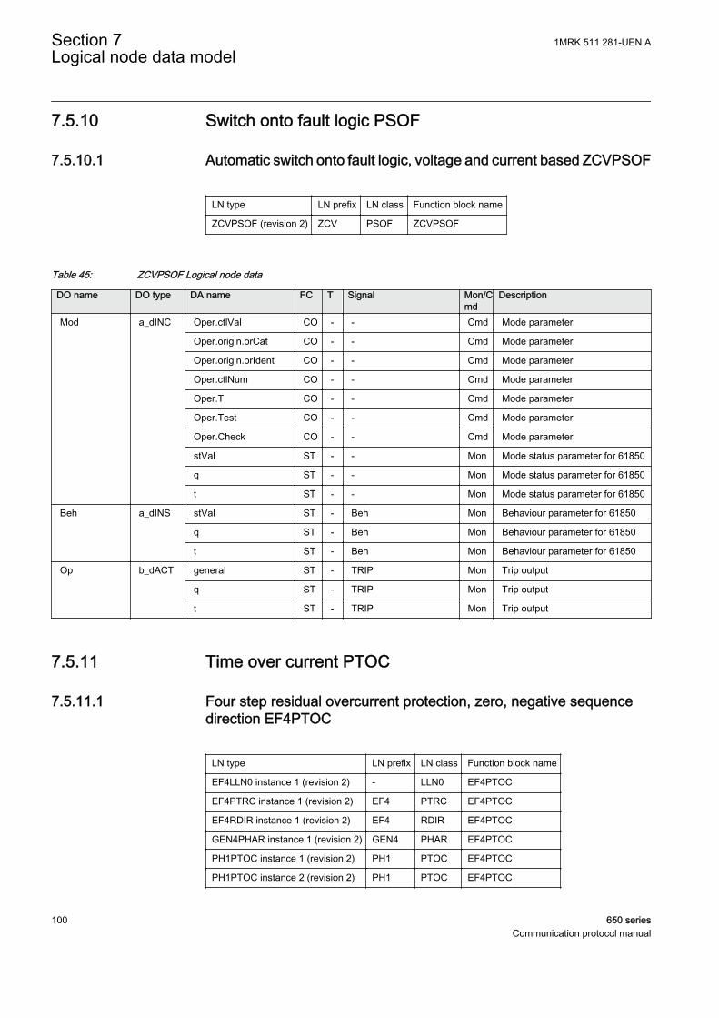
7.5.10 Switch onto fault logic PSOF
7.5.10.1 Automatic switch onto fault logic, voltage and current based ZCVPSOF
LN type LN prefix LN class Function block name
ZCVPSOF (revision 2) ZCV PSOF ZCVPSOF
Table 45: ZCVPSOF Logical node data
DO name DO type DA name FC T Signal Mon/Cmd
Description
Mod a_dINC Oper.ctlVal CO - - Cmd Mode parameter
Oper.origin.orCat CO - - Cmd Mode parameter
Oper.origin.orIdent CO - - Cmd Mode parameter
Oper.ctlNum CO - - Cmd Mode parameter
Oper.T CO - - Cmd Mode parameter
Oper.Test CO - - Cmd Mode parameter
Oper.Check CO - - Cmd Mode parameter
stVal ST - - Mon Mode status parameter for 61850
q ST - - Mon Mode status parameter for 61850
t ST - - Mon Mode status parameter for 61850
Beh a_dINS stVal ST - Beh Mon Behaviour parameter for 61850
q ST - Beh Mon Behaviour parameter for 61850
t ST - Beh Mon Behaviour parameter for 61850
Op b_dACT general ST - TRIP Mon Trip output
q ST - TRIP Mon Trip output
t ST - TRIP Mon Trip output
7.5.11 Time over current PTOC
7.5.11.1 Four step residual overcurrent protection, zero, negative sequencedirection EF4PTOC
LN type LN prefix LN class Function block name
EF4LLN0 instance 1 (revision 2) - LLN0 EF4PTOC
EF4PTRC instance 1 (revision 2) EF4 PTRC EF4PTOC
EF4RDIR instance 1 (revision 2) EF4 RDIR EF4PTOC
GEN4PHAR instance 1 (revision 2) GEN4 PHAR EF4PTOC
PH1PTOC instance 1 (revision 2) PH1 PTOC EF4PTOC
PH1PTOC instance 2 (revision 2) PH1 PTOC EF4PTOC
Section 7 1MRK 511 281-UEN ALogical node data model
100 650 seriesCommunication protocol manual

PH1PTOC instance 3 (revision 2) PH1 PTOC EF4PTOC
PH1PTOC instance 4 (revision 2) PH1 PTOC EF4PTOC
Table 46: EF4PTOC Logical node data (instance 1)
DO name DO type DA name FC T Signal Mon/Cmd
Description
Mod a_dINC Oper.ctlVal CO - - Cmd Mode parameter for 61850
Oper.origin.orCat CO - - Cmd Mode parameter for 61850
Oper.origin.orIdent CO - - Cmd Mode parameter for 61850
Oper.ctlNum CO - - Cmd Mode parameter for 61850
Oper.T CO - - Cmd Mode parameter for 61850
Oper.Test CO - - Cmd Mode parameter for 61850
Oper.Check CO - - Cmd Mode parameter for 61850
stVal ST - - Mon Mode status value parameter for61850
q ST - - Mon Mode status value parameter for61850
t ST - - Mon Mode status value parameter for61850
Beh a_dINS stVal ST - Beh Mon Behaviour parameter for 61850
q ST - Beh Mon Behaviour parameter for 61850
t ST - Beh Mon Behaviour parameter for 61850
Table 47: EF4PTOC Logical node data (instance 1)
DO name DO type DA name FC T Signal Mon/Cmd
Description
Beh a_dINS stVal ST - Beh Mon Behaviour parameter for 61850
q ST - Beh Mon Behaviour parameter for 61850
t ST - Beh Mon Behaviour parameter for 61850
Str b_dACD general ST - START Mon General start signal
q ST - START Mon General start signal
t ST - START Mon General start signal
Op b_dACT general ST T TRIP Mon General trip signal
q ST T TRIP Mon General trip signal
t ST T TRIP Mon General trip signal
Mod c_dINC stVal ST - - Mon Mode status value parameter for61850
q ST - - Mon Mode status value parameter for61850
t ST - - Mon Mode status value parameter for61850
1MRK 511 281-UEN A Section 7Logical node data model
650 series 101Communication protocol manual
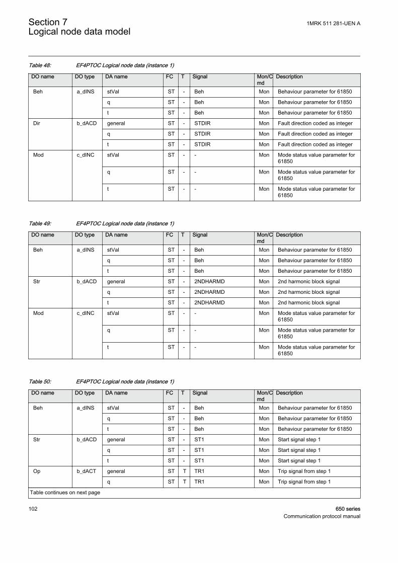
Table 48: EF4PTOC Logical node data (instance 1)
DO name DO type DA name FC T Signal Mon/Cmd
Description
Beh a_dINS stVal ST - Beh Mon Behaviour parameter for 61850
q ST - Beh Mon Behaviour parameter for 61850
t ST - Beh Mon Behaviour parameter for 61850
Dir b_dACD general ST - STDIR Mon Fault direction coded as integer
q ST - STDIR Mon Fault direction coded as integer
t ST - STDIR Mon Fault direction coded as integer
Mod c_dINC stVal ST - - Mon Mode status value parameter for61850
q ST - - Mon Mode status value parameter for61850
t ST - - Mon Mode status value parameter for61850
Table 49: EF4PTOC Logical node data (instance 1)
DO name DO type DA name FC T Signal Mon/Cmd
Description
Beh a_dINS stVal ST - Beh Mon Behaviour parameter for 61850
q ST - Beh Mon Behaviour parameter for 61850
t ST - Beh Mon Behaviour parameter for 61850
Str b_dACD general ST - 2NDHARMD Mon 2nd harmonic block signal
q ST - 2NDHARMD Mon 2nd harmonic block signal
t ST - 2NDHARMD Mon 2nd harmonic block signal
Mod c_dINC stVal ST - - Mon Mode status value parameter for61850
q ST - - Mon Mode status value parameter for61850
t ST - - Mon Mode status value parameter for61850
Table 50: EF4PTOC Logical node data (instance 1)
DO name DO type DA name FC T Signal Mon/Cmd
Description
Beh a_dINS stVal ST - Beh Mon Behaviour parameter for 61850
q ST - Beh Mon Behaviour parameter for 61850
t ST - Beh Mon Behaviour parameter for 61850
Str b_dACD general ST - ST1 Mon Start signal step 1
q ST - ST1 Mon Start signal step 1
t ST - ST1 Mon Start signal step 1
Op b_dACT general ST T TR1 Mon Trip signal from step 1
q ST T TR1 Mon Trip signal from step 1
Table continues on next page
Section 7 1MRK 511 281-UEN ALogical node data model
102 650 seriesCommunication protocol manual
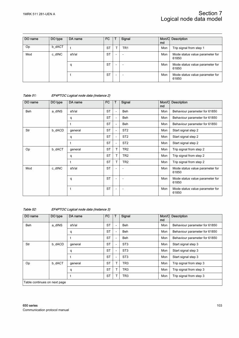
DO name DO type DA name FC T Signal Mon/Cmd
Description
Op b_dACT t ST T TR1 Mon Trip signal from step 1
Mod c_dINC stVal ST - - Mon Mode status value parameter for61850
q ST - - Mon Mode status value parameter for61850
t ST - - Mon Mode status value parameter for61850
Table 51: EF4PTOC Logical node data (instance 2)
DO name DO type DA name FC T Signal Mon/Cmd
Description
Beh a_dINS stVal ST - Beh Mon Behaviour parameter for 61850
q ST - Beh Mon Behaviour parameter for 61850
t ST - Beh Mon Behaviour parameter for 61850
Str b_dACD general ST - ST2 Mon Start signal step 2
q ST - ST2 Mon Start signal step 2
t ST - ST2 Mon Start signal step 2
Op b_dACT general ST T TR2 Mon Trip signal from step 2
q ST T TR2 Mon Trip signal from step 2
t ST T TR2 Mon Trip signal from step 2
Mod c_dINC stVal ST - - Mon Mode status value parameter for61850
q ST - - Mon Mode status value parameter for61850
t ST - - Mon Mode status value parameter for61850
Table 52: EF4PTOC Logical node data (instance 3)
DO name DO type DA name FC T Signal Mon/Cmd
Description
Beh a_dINS stVal ST - Beh Mon Behaviour parameter for 61850
q ST - Beh Mon Behaviour parameter for 61850
t ST - Beh Mon Behaviour parameter for 61850
Str b_dACD general ST - ST3 Mon Start signal step 3
q ST - ST3 Mon Start signal step 3
t ST - ST3 Mon Start signal step 3
Op b_dACT general ST T TR3 Mon Trip signal from step 3
q ST T TR3 Mon Trip signal from step 3
t ST T TR3 Mon Trip signal from step 3
Table continues on next page
1MRK 511 281-UEN A Section 7Logical node data model
650 series 103Communication protocol manual
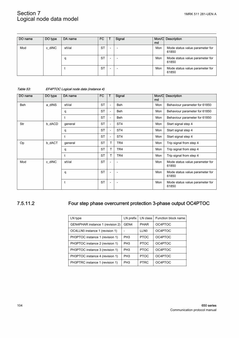
DO name DO type DA name FC T Signal Mon/Cmd
Description
Mod c_dINC stVal ST - - Mon Mode status value parameter for61850
q ST - - Mon Mode status value parameter for61850
t ST - - Mon Mode status value parameter for61850
Table 53: EF4PTOC Logical node data (instance 4)
DO name DO type DA name FC T Signal Mon/Cmd
Description
Beh a_dINS stVal ST - Beh Mon Behaviour parameter for 61850
q ST - Beh Mon Behaviour parameter for 61850
t ST - Beh Mon Behaviour parameter for 61850
Str b_dACD general ST - ST4 Mon Start signal step 4
q ST - ST4 Mon Start signal step 4
t ST - ST4 Mon Start signal step 4
Op b_dACT general ST T TR4 Mon Trip signal from step 4
q ST T TR4 Mon Trip signal from step 4
t ST T TR4 Mon Trip signal from step 4
Mod c_dINC stVal ST - - Mon Mode status value parameter for61850
q ST - - Mon Mode status value parameter for61850
t ST - - Mon Mode status value parameter for61850
7.5.11.2 Four step phase overcurrent protection 3-phase output OC4PTOC
LN type LN prefix LN class Function block name
GEN4PHAR instance 1 (revision 2) GEN4 PHAR OC4PTOC
OC4LLN0 instance 1 (revision 1) - LLN0 OC4PTOC
PH3PTOC instance 1 (revision 1) PH3 PTOC OC4PTOC
PH3PTOC instance 2 (revision 1) PH3 PTOC OC4PTOC
PH3PTOC instance 3 (revision 1) PH3 PTOC OC4PTOC
PH3PTOC instance 4 (revision 1) PH3 PTOC OC4PTOC
PH3PTRC instance 1 (revision 1) PH3 PTRC OC4PTOC
Section 7 1MRK 511 281-UEN ALogical node data model
104 650 seriesCommunication protocol manual
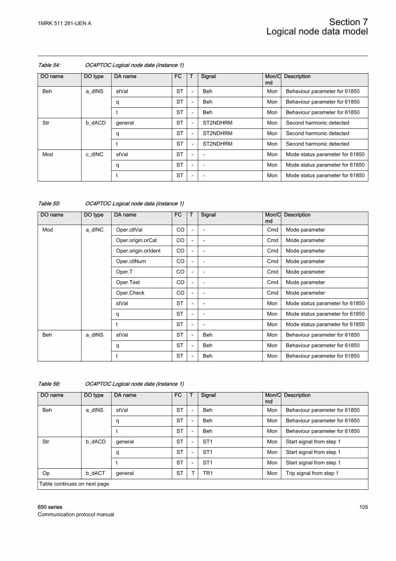
Table 54: OC4PTOC Logical node data (instance 1)
DO name DO type DA name FC T Signal Mon/Cmd
Description
Beh a_dINS stVal ST - Beh Mon Behaviour parameter for 61850
q ST - Beh Mon Behaviour parameter for 61850
t ST - Beh Mon Behaviour parameter for 61850
Str b_dACD general ST - ST2NDHRM Mon Second harmonic detected
q ST - ST2NDHRM Mon Second harmonic detected
t ST - ST2NDHRM Mon Second harmonic detected
Mod c_dINC stVal ST - - Mon Mode status parameter for 61850
q ST - - Mon Mode status parameter for 61850
t ST - - Mon Mode status parameter for 61850
Table 55: OC4PTOC Logical node data (instance 1)
DO name DO type DA name FC T Signal Mon/Cmd
Description
Mod a_dINC Oper.ctlVal CO - - Cmd Mode parameter
Oper.origin.orCat CO - - Cmd Mode parameter
Oper.origin.orIdent CO - - Cmd Mode parameter
Oper.ctlNum CO - - Cmd Mode parameter
Oper.T CO - - Cmd Mode parameter
Oper.Test CO - - Cmd Mode parameter
Oper.Check CO - - Cmd Mode parameter
stVal ST - - Mon Mode status parameter for 61850
q ST - - Mon Mode status parameter for 61850
t ST - - Mon Mode status parameter for 61850
Beh a_dINS stVal ST - Beh Mon Behaviour parameter for 61850
q ST - Beh Mon Behaviour parameter for 61850
t ST - Beh Mon Behaviour parameter for 61850
Table 56: OC4PTOC Logical node data (instance 1)
DO name DO type DA name FC T Signal Mon/Cmd
Description
Beh a_dINS stVal ST - Beh Mon Behaviour parameter for 61850
q ST - Beh Mon Behaviour parameter for 61850
t ST - Beh Mon Behaviour parameter for 61850
Str b_dACD general ST - ST1 Mon Start signal from step 1
q ST - ST1 Mon Start signal from step 1
t ST - ST1 Mon Start signal from step 1
Op b_dACT general ST T TR1 Mon Trip signal from step 1
Table continues on next page
1MRK 511 281-UEN A Section 7Logical node data model
650 series 105Communication protocol manual

DO name DO type DA name FC T Signal Mon/Cmd
Description
Op b_dACT q ST T TR1 Mon Trip signal from step 1
t ST T TR1 Mon Trip signal from step 1
Mod c_dINC stVal ST - - Mon Mode status parameter for 61850
q ST - - Mon Mode status parameter for 61850
t ST - - Mon Mode status parameter for 61850
Table 57: OC4PTOC Logical node data (instance 2)
DO name DO type DA name FC T Signal Mon/Cmd
Description
Beh a_dINS stVal ST - Beh Mon Behaviour parameter for 61850
q ST - Beh Mon Behaviour parameter for 61850
t ST - Beh Mon Behaviour parameter for 61850
Str b_dACD general ST - ST2 Mon Start signal from step 2
q ST - ST2 Mon Start signal from step 2
t ST - ST2 Mon Start signal from step 2
Op b_dACT general ST T TR2 Mon Trip signal from step 2
q ST T TR2 Mon Trip signal from step 2
t ST T TR2 Mon Trip signal from step 2
Mod c_dINC stVal ST - - Mon Mode status parameter for 61850
q ST - - Mon Mode status parameter for 61850
t ST - - Mon Mode status parameter for 61850
Table 58: OC4PTOC Logical node data (instance 3)
DO name DO type DA name FC T Signal Mon/Cmd
Description
Beh a_dINS stVal ST - Beh Mon Behaviour parameter for 61850
q ST - Beh Mon Behaviour parameter for 61850
t ST - Beh Mon Behaviour parameter for 61850
Str b_dACD general ST - ST3 Mon Start signal from step 3
q ST - ST3 Mon Start signal from step 3
t ST - ST3 Mon Start signal from step 3
Op b_dACT general ST T TR3 Mon Trip signal from step 3
q ST T TR3 Mon Trip signal from step 3
t ST T TR3 Mon Trip signal from step 3
Mod c_dINC stVal ST - - Mon Mode status parameter for 61850
q ST - - Mon Mode status parameter for 61850
t ST - - Mon Mode status parameter for 61850
Section 7 1MRK 511 281-UEN ALogical node data model
106 650 seriesCommunication protocol manual
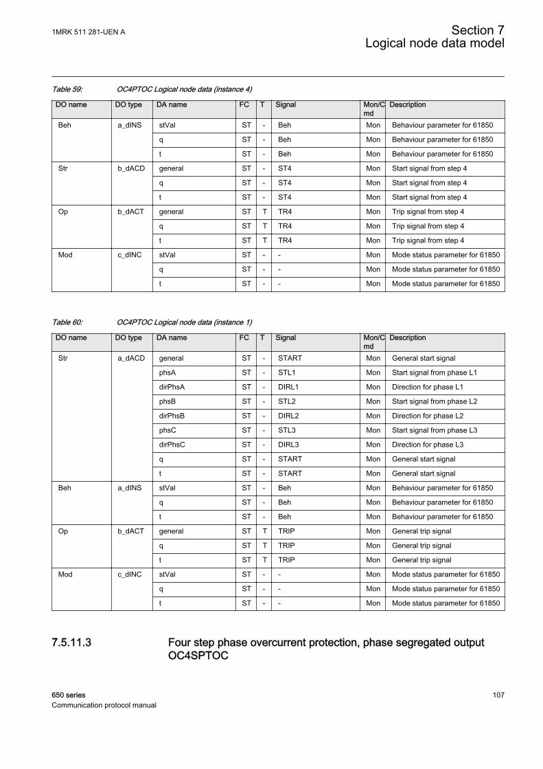
Table 59: OC4PTOC Logical node data (instance 4)
DO name DO type DA name FC T Signal Mon/Cmd
Description
Beh a_dINS stVal ST - Beh Mon Behaviour parameter for 61850
q ST - Beh Mon Behaviour parameter for 61850
t ST - Beh Mon Behaviour parameter for 61850
Str b_dACD general ST - ST4 Mon Start signal from step 4
q ST - ST4 Mon Start signal from step 4
t ST - ST4 Mon Start signal from step 4
Op b_dACT general ST T TR4 Mon Trip signal from step 4
q ST T TR4 Mon Trip signal from step 4
t ST T TR4 Mon Trip signal from step 4
Mod c_dINC stVal ST - - Mon Mode status parameter for 61850
q ST - - Mon Mode status parameter for 61850
t ST - - Mon Mode status parameter for 61850
Table 60: OC4PTOC Logical node data (instance 1)
DO name DO type DA name FC T Signal Mon/Cmd
Description
Str a_dACD general ST - START Mon General start signal
phsA ST - STL1 Mon Start signal from phase L1
dirPhsA ST - DIRL1 Mon Direction for phase L1
phsB ST - STL2 Mon Start signal from phase L2
dirPhsB ST - DIRL2 Mon Direction for phase L2
phsC ST - STL3 Mon Start signal from phase L3
dirPhsC ST - DIRL3 Mon Direction for phase L3
q ST - START Mon General start signal
t ST - START Mon General start signal
Beh a_dINS stVal ST - Beh Mon Behaviour parameter for 61850
q ST - Beh Mon Behaviour parameter for 61850
t ST - Beh Mon Behaviour parameter for 61850
Op b_dACT general ST T TRIP Mon General trip signal
q ST T TRIP Mon General trip signal
t ST T TRIP Mon General trip signal
Mod c_dINC stVal ST - - Mon Mode status parameter for 61850
q ST - - Mon Mode status parameter for 61850
t ST - - Mon Mode status parameter for 61850
7.5.11.3 Four step phase overcurrent protection, phase segregated outputOC4SPTOC
1MRK 511 281-UEN A Section 7Logical node data model
650 series 107Communication protocol manual
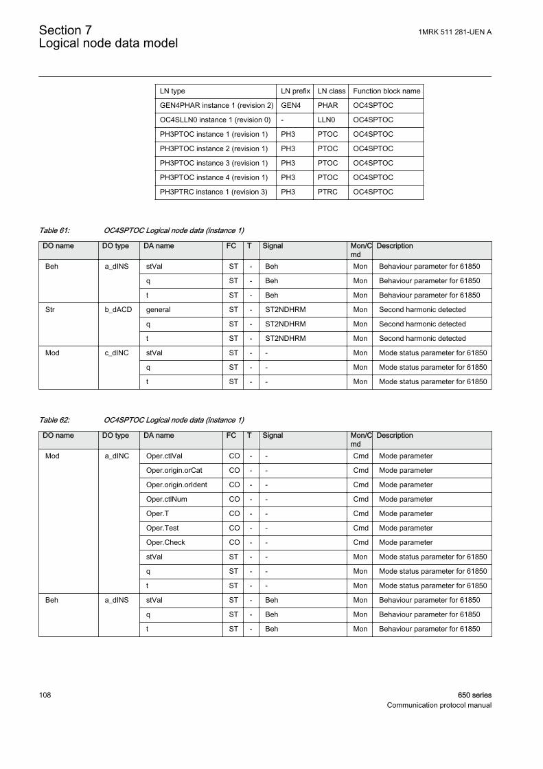
LN type LN prefix LN class Function block name
GEN4PHAR instance 1 (revision 2) GEN4 PHAR OC4SPTOC
OC4SLLN0 instance 1 (revision 0) - LLN0 OC4SPTOC
PH3PTOC instance 1 (revision 1) PH3 PTOC OC4SPTOC
PH3PTOC instance 2 (revision 1) PH3 PTOC OC4SPTOC
PH3PTOC instance 3 (revision 1) PH3 PTOC OC4SPTOC
PH3PTOC instance 4 (revision 1) PH3 PTOC OC4SPTOC
PH3PTRC instance 1 (revision 3) PH3 PTRC OC4SPTOC
Table 61: OC4SPTOC Logical node data (instance 1)
DO name DO type DA name FC T Signal Mon/Cmd
Description
Beh a_dINS stVal ST - Beh Mon Behaviour parameter for 61850
q ST - Beh Mon Behaviour parameter for 61850
t ST - Beh Mon Behaviour parameter for 61850
Str b_dACD general ST - ST2NDHRM Mon Second harmonic detected
q ST - ST2NDHRM Mon Second harmonic detected
t ST - ST2NDHRM Mon Second harmonic detected
Mod c_dINC stVal ST - - Mon Mode status parameter for 61850
q ST - - Mon Mode status parameter for 61850
t ST - - Mon Mode status parameter for 61850
Table 62: OC4SPTOC Logical node data (instance 1)
DO name DO type DA name FC T Signal Mon/Cmd
Description
Mod a_dINC Oper.ctlVal CO - - Cmd Mode parameter
Oper.origin.orCat CO - - Cmd Mode parameter
Oper.origin.orIdent CO - - Cmd Mode parameter
Oper.ctlNum CO - - Cmd Mode parameter
Oper.T CO - - Cmd Mode parameter
Oper.Test CO - - Cmd Mode parameter
Oper.Check CO - - Cmd Mode parameter
stVal ST - - Mon Mode status parameter for 61850
q ST - - Mon Mode status parameter for 61850
t ST - - Mon Mode status parameter for 61850
Beh a_dINS stVal ST - Beh Mon Behaviour parameter for 61850
q ST - Beh Mon Behaviour parameter for 61850
t ST - Beh Mon Behaviour parameter for 61850
Section 7 1MRK 511 281-UEN ALogical node data model
108 650 seriesCommunication protocol manual

Table 63: OC4SPTOC Logical node data (instance 1)
DO name DO type DA name FC T Signal Mon/Cmd
Description
Beh a_dINS stVal ST - Beh Mon Behaviour parameter for 61850
q ST - Beh Mon Behaviour parameter for 61850
t ST - Beh Mon Behaviour parameter for 61850
Str b_dACD general ST - ST1 Mon Start signal from step 1
q ST - ST1 Mon Start signal from step 1
t ST - ST1 Mon Start signal from step 1
Op b_dACT general ST T TR1 Mon Trip signal from step 1
q ST T TR1 Mon Trip signal from step 1
t ST T TR1 Mon Trip signal from step 1
Mod c_dINC stVal ST - - Mon Mode status parameter for 61850
q ST - - Mon Mode status parameter for 61850
t ST - - Mon Mode status parameter for 61850
Table 64: OC4SPTOC Logical node data (instance 2)
DO name DO type DA name FC T Signal Mon/Cmd
Description
Beh a_dINS stVal ST - Beh Mon Behaviour parameter for 61850
q ST - Beh Mon Behaviour parameter for 61850
t ST - Beh Mon Behaviour parameter for 61850
Str b_dACD general ST - ST2 Mon Start signal from step 2
q ST - ST2 Mon Start signal from step 2
t ST - ST2 Mon Start signal from step 2
Op b_dACT general ST T TR2 Mon Trip signal from step 2
q ST T TR2 Mon Trip signal from step 2
t ST T TR2 Mon Trip signal from step 2
Mod c_dINC stVal ST - - Mon Mode status parameter for 61850
q ST - - Mon Mode status parameter for 61850
t ST - - Mon Mode status parameter for 61850
Table 65: OC4SPTOC Logical node data (instance 3)
DO name DO type DA name FC T Signal Mon/Cmd
Description
Beh a_dINS stVal ST - Beh Mon Behaviour parameter for 61850
q ST - Beh Mon Behaviour parameter for 61850
t ST - Beh Mon Behaviour parameter for 61850
Str b_dACD general ST - ST3 Mon Start signal from step 3
q ST - ST3 Mon Start signal from step 3
Table continues on next page
1MRK 511 281-UEN A Section 7Logical node data model
650 series 109Communication protocol manual
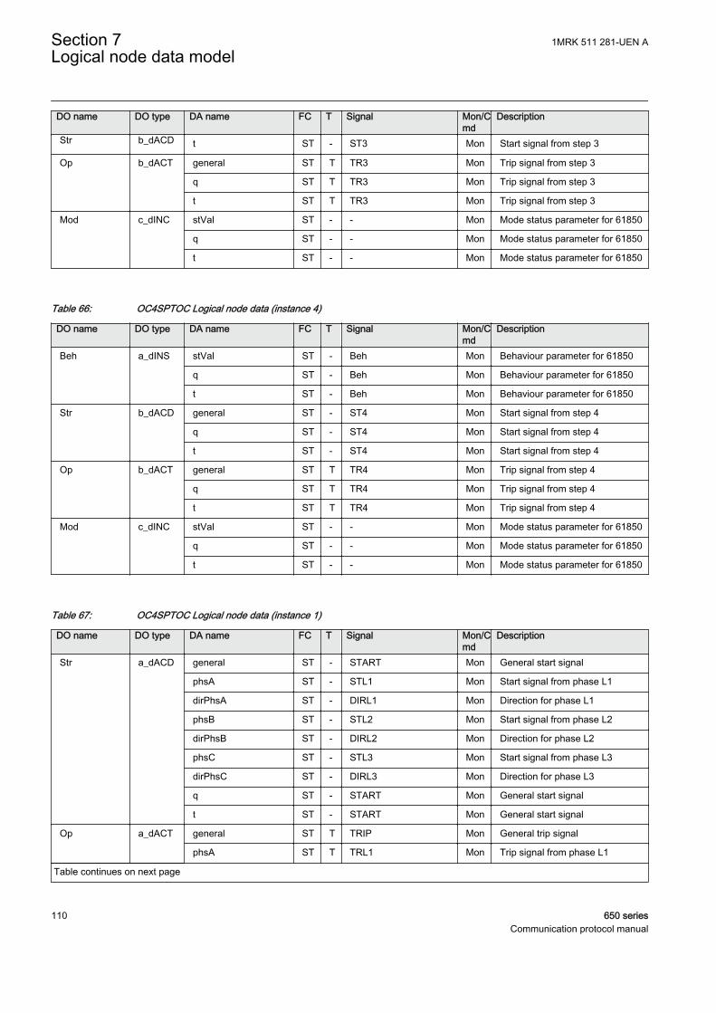
DO name DO type DA name FC T Signal Mon/Cmd
Description
Str b_dACD t ST - ST3 Mon Start signal from step 3
Op b_dACT general ST T TR3 Mon Trip signal from step 3
q ST T TR3 Mon Trip signal from step 3
t ST T TR3 Mon Trip signal from step 3
Mod c_dINC stVal ST - - Mon Mode status parameter for 61850
q ST - - Mon Mode status parameter for 61850
t ST - - Mon Mode status parameter for 61850
Table 66: OC4SPTOC Logical node data (instance 4)
DO name DO type DA name FC T Signal Mon/Cmd
Description
Beh a_dINS stVal ST - Beh Mon Behaviour parameter for 61850
q ST - Beh Mon Behaviour parameter for 61850
t ST - Beh Mon Behaviour parameter for 61850
Str b_dACD general ST - ST4 Mon Start signal from step 4
q ST - ST4 Mon Start signal from step 4
t ST - ST4 Mon Start signal from step 4
Op b_dACT general ST T TR4 Mon Trip signal from step 4
q ST T TR4 Mon Trip signal from step 4
t ST T TR4 Mon Trip signal from step 4
Mod c_dINC stVal ST - - Mon Mode status parameter for 61850
q ST - - Mon Mode status parameter for 61850
t ST - - Mon Mode status parameter for 61850
Table 67: OC4SPTOC Logical node data (instance 1)
DO name DO type DA name FC T Signal Mon/Cmd
Description
Str a_dACD general ST - START Mon General start signal
phsA ST - STL1 Mon Start signal from phase L1
dirPhsA ST - DIRL1 Mon Direction for phase L1
phsB ST - STL2 Mon Start signal from phase L2
dirPhsB ST - DIRL2 Mon Direction for phase L2
phsC ST - STL3 Mon Start signal from phase L3
dirPhsC ST - DIRL3 Mon Direction for phase L3
q ST - START Mon General start signal
t ST - START Mon General start signal
Op a_dACT general ST T TRIP Mon General trip signal
phsA ST T TRL1 Mon Trip signal from phase L1
Table continues on next page
Section 7 1MRK 511 281-UEN ALogical node data model
110 650 seriesCommunication protocol manual
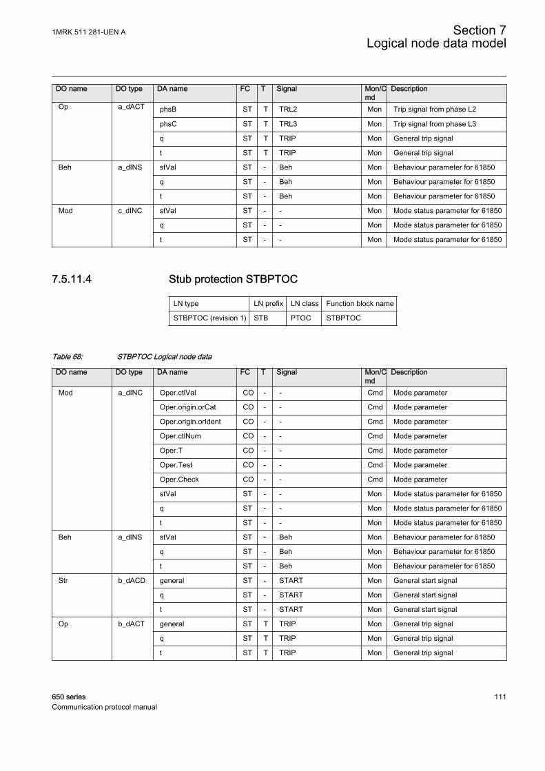
DO name DO type DA name FC T Signal Mon/Cmd
Description
Op a_dACT phsB ST T TRL2 Mon Trip signal from phase L2
phsC ST T TRL3 Mon Trip signal from phase L3
q ST T TRIP Mon General trip signal
t ST T TRIP Mon General trip signal
Beh a_dINS stVal ST - Beh Mon Behaviour parameter for 61850
q ST - Beh Mon Behaviour parameter for 61850
t ST - Beh Mon Behaviour parameter for 61850
Mod c_dINC stVal ST - - Mon Mode status parameter for 61850
q ST - - Mon Mode status parameter for 61850
t ST - - Mon Mode status parameter for 61850
7.5.11.4 Stub protection STBPTOC
LN type LN prefix LN class Function block name
STBPTOC (revision 1) STB PTOC STBPTOC
Table 68: STBPTOC Logical node data
DO name DO type DA name FC T Signal Mon/Cmd
Description
Mod a_dINC Oper.ctlVal CO - - Cmd Mode parameter
Oper.origin.orCat CO - - Cmd Mode parameter
Oper.origin.orIdent CO - - Cmd Mode parameter
Oper.ctlNum CO - - Cmd Mode parameter
Oper.T CO - - Cmd Mode parameter
Oper.Test CO - - Cmd Mode parameter
Oper.Check CO - - Cmd Mode parameter
stVal ST - - Mon Mode status parameter for 61850
q ST - - Mon Mode status parameter for 61850
t ST - - Mon Mode status parameter for 61850
Beh a_dINS stVal ST - Beh Mon Behaviour parameter for 61850
q ST - Beh Mon Behaviour parameter for 61850
t ST - Beh Mon Behaviour parameter for 61850
Str b_dACD general ST - START Mon General start signal
q ST - START Mon General start signal
t ST - START Mon General start signal
Op b_dACT general ST T TRIP Mon General trip signal
q ST T TRIP Mon General trip signal
t ST T TRIP Mon General trip signal
1MRK 511 281-UEN A Section 7Logical node data model
650 series 111Communication protocol manual

7.5.11.5 Broken conductor check BRCPTOC
LN type LN prefix LN class Function block name
BRCPTOC (revision 1) BRC PTOC BRCPTOC
Table 69: BRCPTOC Logical node data
DO name DO type DA name FC T Signal Mon/Cmd
Description
Mod a_dINC Oper.ctlVal CO - - Cmd Mode parameter
Oper.origin.orCat CO - - Cmd Mode parameter
Oper.origin.orIdent CO - - Cmd Mode parameter
Oper.ctlNum CO - - Cmd Mode parameter
Oper.T CO - - Cmd Mode parameter
Oper.Test CO - - Cmd Mode parameter
Oper.Check CO - - Cmd Mode parameter
stVal ST - - Mon Mode status parameter for 61850
q ST - - Mon Mode status parameter for 61850
t ST - - Mon Mode status parameter for 61850
Beh a_dINS stVal ST - Beh Mon Behaviour parameter for 61850
q ST - Beh Mon Behaviour parameter for 61850
t ST - Beh Mon Behaviour parameter for 61850
Str b_dACD general ST - START Mon Start signal of the protection logic
q ST - START Mon Start signal of the protection logic
t ST - START Mon Start signal of the protection logic
Op b_dACT general ST T TRIP Mon Operate signal of the protectionlogic
q ST T TRIP Mon Operate signal of the protectionlogic
t ST T TRIP Mon Operate signal of the protectionlogic
StrDur v2_dMV mag.f MX - - Mon Start duration in per cents of thetotal operating time
q MX - - Mon Start duration in per cents of thetotal operating time
t MX - - Mon Start duration in per cents of thetotal operating time
7.5.11.6 Negative sequence based overcurrent function DNSPTOC
LN type LN prefix LN class Function block name
NSDLLN0 instance 1 (revision 2) - LLN0 DNSPTOC
PH1PTOC instance 1 (revision 2) PH1 PTOC DNSPTOC
PH1PTOC instance 2 (revision 2) PH1 PTOC DNSPTOC
Section 7 1MRK 511 281-UEN ALogical node data model
112 650 seriesCommunication protocol manual
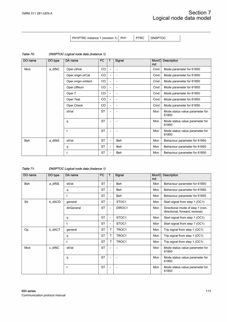
PH1PTRC instance 1 (revision 1) PH1 PTRC DNSPTOC
Table 70: DNSPTOC Logical node data (instance 1)
DO name DO type DA name FC T Signal Mon/Cmd
Description
Mod a_dINC Oper.ctlVal CO - - Cmd Mode parameter for 61850
Oper.origin.orCat CO - - Cmd Mode parameter for 61850
Oper.origin.orIdent CO - - Cmd Mode parameter for 61850
Oper.ctlNum CO - - Cmd Mode parameter for 61850
Oper.T CO - - Cmd Mode parameter for 61850
Oper.Test CO - - Cmd Mode parameter for 61850
Oper.Check CO - - Cmd Mode parameter for 61850
stVal ST - - Mon Mode status value parameter for61850
q ST - - Mon Mode status value parameter for61850
t ST - - Mon Mode status value parameter for61850
Beh a_dINS stVal ST - Beh Mon Behaviour parameter for 61850
q ST - Beh Mon Behaviour parameter for 61850
t ST - Beh Mon Behaviour parameter for 61850
Table 71: DNSPTOC Logical node data (instance 1)
DO name DO type DA name FC T Signal Mon/Cmd
Description
Beh a_dINS stVal ST - Beh Mon Behaviour parameter for 61850
q ST - Beh Mon Behaviour parameter for 61850
t ST - Beh Mon Behaviour parameter for 61850
Str b_dACD general ST - STOC1 Mon Start signal from step 1 (OC1)
dirGeneral ST - DIROC1 Mon Directional mode of step 1 (non-directional, forward, reverse)
q ST - STOC1 Mon Start signal from step 1 (OC1)
t ST - STOC1 Mon Start signal from step 1 (OC1)
Op b_dACT general ST T TROC1 Mon Trip signal from step 1 (OC1)
q ST T TROC1 Mon Trip signal from step 1 (OC1)
t ST T TROC1 Mon Trip signal from step 1 (OC1)
Mod c_dINC stVal ST - - Mon Mode status value parameter for61850
q ST - - Mon Mode status value parameter for61850
t ST - - Mon Mode status value parameter for61850
1MRK 511 281-UEN A Section 7Logical node data model
650 series 113Communication protocol manual

Table 72: DNSPTOC Logical node data (instance 2)
DO name DO type DA name FC T Signal Mon/Cmd
Description
Beh a_dINS stVal ST - Beh Mon Behaviour parameter for 61850
q ST - Beh Mon Behaviour parameter for 61850
t ST - Beh Mon Behaviour parameter for 61850
Str b_dACD general ST - STOC2 Mon Start signal from step 2 (OC2)
dirGeneral ST - DIROC2 Mon Directional mode of step 2 (non-directional, forward, reverse)
q ST - STOC2 Mon Start signal from step 2 (OC2)
t ST - STOC2 Mon Start signal from step 2 (OC2)
Op b_dACT general ST T TROC2 Mon Trip signal from step 2 (OC2)
q ST T TROC2 Mon Trip signal from step 2 (OC2)
t ST T TROC2 Mon Trip signal from step 2 (OC2)
Mod c_dINC stVal ST - - Mon Mode status value parameter for61850
q ST - - Mon Mode status value parameter for61850
t ST - - Mon Mode status value parameter for61850
Table 73: DNSPTOC Logical node data (instance 1)
DO name DO type DA name FC T Signal Mon/Cmd
Description
Beh a_dINS stVal ST - Beh Mon Behaviour parameter for 61850
q ST - Beh Mon Behaviour parameter for 61850
t ST - Beh Mon Behaviour parameter for 61850
Str b_dACD general ST - START Mon General start signal
q ST - START Mon General start signal
t ST - START Mon General start signal
Op b_dACT general ST T TRIP Mon General trip signal
q ST T TRIP Mon General trip signal
t ST T TRIP Mon General trip signal
Mod c_dINC stVal ST - - Mon Mode status value parameter for61850
q ST - - Mon Mode status value parameter for61850
t ST - - Mon Mode status value parameter for61850
Section 7 1MRK 511 281-UEN ALogical node data model
114 650 seriesCommunication protocol manual
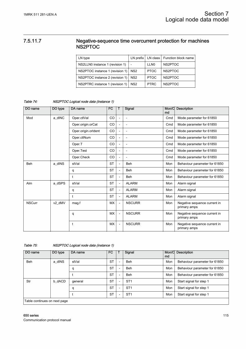
7.5.11.7 Negative-sequence time overcurrent protection for machinesNS2PTOC
LN type LN prefix LN class Function block name
NS2LLN0 instance 1 (revision 1) - LLN0 NS2PTOC
NS2PTOC instance 1 (revision 1) NS2 PTOC NS2PTOC
NS2PTOC instance 2 (revision 1) NS2 PTOC NS2PTOC
NS2PTRC instance 1 (revision 1) NS2 PTRC NS2PTOC
Table 74: NS2PTOC Logical node data (instance 1)
DO name DO type DA name FC T Signal Mon/Cmd
Description
Mod a_dINC Oper.ctlVal CO - - Cmd Mode parameter for 61850
Oper.origin.orCat CO - - Cmd Mode parameter for 61850
Oper.origin.orIdent CO - - Cmd Mode parameter for 61850
Oper.ctlNum CO - - Cmd Mode parameter for 61850
Oper.T CO - - Cmd Mode parameter for 61850
Oper.Test CO - - Cmd Mode parameter for 61850
Oper.Check CO - - Cmd Mode parameter for 61850
Beh a_dINS stVal ST - Beh Mon Behaviour parameter for 61850
q ST - Beh Mon Behaviour parameter for 61850
t ST - Beh Mon Behaviour parameter for 61850
Alm a_dSPS stVal ST - ALARM Mon Alarm signal
q ST - ALARM Mon Alarm signal
t ST - ALARM Mon Alarm signal
NSCurr v2_dMV mag.f MX - NSCURR Mon Negative sequence current inprimary amps
q MX - NSCURR Mon Negative sequence current inprimary amps
t MX - NSCURR Mon Negative sequence current inprimary amps
Table 75: NS2PTOC Logical node data (instance 1)
DO name DO type DA name FC T Signal Mon/Cmd
Description
Beh a_dINS stVal ST - Beh Mon Behaviour parameter for 61850
q ST - Beh Mon Behaviour parameter for 61850
t ST - Beh Mon Behaviour parameter for 61850
Str b_dACD general ST - ST1 Mon Start signal for step 1
q ST - ST1 Mon Start signal for step 1
t ST - ST1 Mon Start signal for step 1
Table continues on next page
1MRK 511 281-UEN A Section 7Logical node data model
650 series 115Communication protocol manual
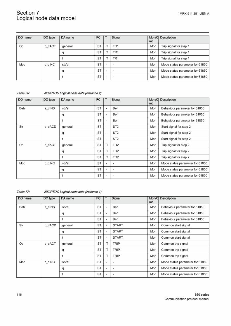
DO name DO type DA name FC T Signal Mon/Cmd
Description
Op b_dACT general ST T TR1 Mon Trip signal for step 1
q ST T TR1 Mon Trip signal for step 1
t ST T TR1 Mon Trip signal for step 1
Mod c_dINC stVal ST - - Mon Mode status parameter for 61850
q ST - - Mon Mode status parameter for 61850
t ST - - Mon Mode status parameter for 61850
Table 76: NS2PTOC Logical node data (instance 2)
DO name DO type DA name FC T Signal Mon/Cmd
Description
Beh a_dINS stVal ST - Beh Mon Behaviour parameter for 61850
q ST - Beh Mon Behaviour parameter for 61850
t ST - Beh Mon Behaviour parameter for 61850
Str b_dACD general ST - ST2 Mon Start signal for step 2
q ST - ST2 Mon Start signal for step 2
t ST - ST2 Mon Start signal for step 2
Op b_dACT general ST T TR2 Mon Trip signal for step 2
q ST T TR2 Mon Trip signal for step 2
t ST T TR2 Mon Trip signal for step 2
Mod c_dINC stVal ST - - Mon Mode status parameter for 61850
q ST - - Mon Mode status parameter for 61850
t ST - - Mon Mode status parameter for 61850
Table 77: NS2PTOC Logical node data (instance 1)
DO name DO type DA name FC T Signal Mon/Cmd
Description
Beh a_dINS stVal ST - Beh Mon Behaviour parameter for 61850
q ST - Beh Mon Behaviour parameter for 61850
t ST - Beh Mon Behaviour parameter for 61850
Str b_dACD general ST - START Mon Common start signal
q ST - START Mon Common start signal
t ST - START Mon Common start signal
Op b_dACT general ST T TRIP Mon Common trip signal
q ST T TRIP Mon Common trip signal
t ST T TRIP Mon Common trip signal
Mod c_dINC stVal ST - - Mon Mode status parameter for 61850
q ST - - Mon Mode status parameter for 61850
t ST - - Mon Mode status parameter for 61850
Section 7 1MRK 511 281-UEN ALogical node data model
116 650 seriesCommunication protocol manual
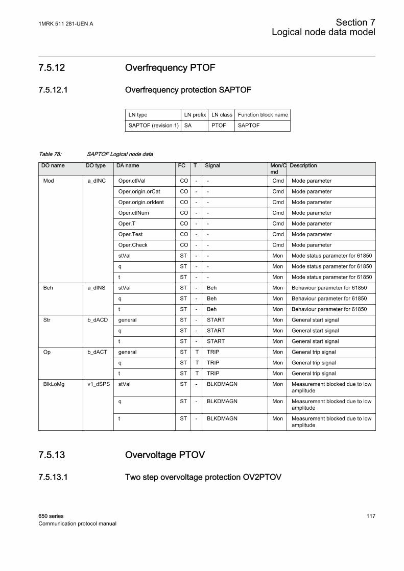
7.5.12 Overfrequency PTOF
7.5.12.1 Overfrequency protection SAPTOF
LN type LN prefix LN class Function block name
SAPTOF (revision 1) SA PTOF SAPTOF
Table 78: SAPTOF Logical node data
DO name DO type DA name FC T Signal Mon/Cmd
Description
Mod a_dINC Oper.ctlVal CO - - Cmd Mode parameter
Oper.origin.orCat CO - - Cmd Mode parameter
Oper.origin.orIdent CO - - Cmd Mode parameter
Oper.ctlNum CO - - Cmd Mode parameter
Oper.T CO - - Cmd Mode parameter
Oper.Test CO - - Cmd Mode parameter
Oper.Check CO - - Cmd Mode parameter
stVal ST - - Mon Mode status parameter for 61850
q ST - - Mon Mode status parameter for 61850
t ST - - Mon Mode status parameter for 61850
Beh a_dINS stVal ST - Beh Mon Behaviour parameter for 61850
q ST - Beh Mon Behaviour parameter for 61850
t ST - Beh Mon Behaviour parameter for 61850
Str b_dACD general ST - START Mon General start signal
q ST - START Mon General start signal
t ST - START Mon General start signal
Op b_dACT general ST T TRIP Mon General trip signal
q ST T TRIP Mon General trip signal
t ST T TRIP Mon General trip signal
BlkLoMg v1_dSPS stVal ST - BLKDMAGN Mon Measurement blocked due to lowamplitude
q ST - BLKDMAGN Mon Measurement blocked due to lowamplitude
t ST - BLKDMAGN Mon Measurement blocked due to lowamplitude
7.5.13 Overvoltage PTOV
7.5.13.1 Two step overvoltage protection OV2PTOV
1MRK 511 281-UEN A Section 7Logical node data model
650 series 117Communication protocol manual

LN type LN prefix LN class Function block name
GEN2LLN0 instance 1 (revision 1) - LLN0 OV2PTOV
OV2PTOV instance 1 (revision 1) OV2 PTOV OV2PTOV
OV2PTOV instance 2 (revision 1) OV2 PTOV OV2PTOV
PH3PTRC instance 1 (revision 1) PH3 PTRC OV2PTOV
Table 79: OV2PTOV Logical node data (instance 1)
DO name DO type DA name FC T Signal Mon/Cmd
Description
Mod a_dINC Oper.ctlVal CO - - Cmd Mode parameter
Oper.origin.orCat CO - - Cmd Mode parameter
Oper.origin.orIdent CO - - Cmd Mode parameter
Oper.ctlNum CO - - Cmd Mode parameter
Oper.T CO - - Cmd Mode parameter
Oper.Test CO - - Cmd Mode parameter
Oper.Check CO - - Cmd Mode parameter
stVal ST - - Mon Mode status parameter for 61850
q ST - - Mon Mode status parameter for 61850
t ST - - Mon Mode status parameter for 61850
Beh a_dINS stVal ST - Beh Mon Behaviour parameter for 61850
q ST - Beh Mon Behaviour parameter for 61850
t ST - Beh Mon Behaviour parameter for 61850
Table 80: OV2PTOV Logical node data (instance 1)
DO name DO type DA name FC T Signal Mon/Cmd
Description
Str a_dACD general ST - ST1 Mon Start signal from step 1
phsA ST - ST1L1 Mon Start signal from step 1 phase L1
phsB ST - ST1L2 Mon Start signal from step 1 phase L2
phsC ST - ST1L3 Mon Start signal from step 1 phase L3
q ST - ST1 Mon Start signal from step 1
t ST - ST1 Mon Start signal from step 1
Beh a_dINS stVal ST - Beh Mon Behaviour parameter for 61850
q ST - Beh Mon Behaviour parameter for 61850
t ST - Beh Mon Behaviour parameter for 61850
Op b_dACT general ST T TR1 Mon Trip signal from step 1
q ST T TR1 Mon Trip signal from step 1
t ST T TR1 Mon Trip signal from step 1
Mod c_dINC stVal ST - - Mon Mode status parameter for 61850
q ST - - Mon Mode status parameter for 61850
t ST - - Mon Mode status parameter for 61850
Section 7 1MRK 511 281-UEN ALogical node data model
118 650 seriesCommunication protocol manual

Table 81: OV2PTOV Logical node data (instance 2)
DO name DO type DA name FC T Signal Mon/Cmd
Description
Str a_dACD general ST - ST2 Mon Start signal from step 2
phsA ST - - Mon Start signal from step2 phase L1
phsB ST - - Mon Start signal from step2 phase L2
phsC ST - - Mon Start signal from step2 phase L3
q ST - ST2 Mon Start signal from step 2
t ST - ST2 Mon Start signal from step 2
Beh a_dINS stVal ST - Beh Mon Behaviour parameter for 61850
q ST - Beh Mon Behaviour parameter for 61850
t ST - Beh Mon Behaviour parameter for 61850
Op b_dACT general ST T TR2 Mon Trip signal from step 2
q ST T TR2 Mon Trip signal from step 2
t ST T TR2 Mon Trip signal from step 2
Mod c_dINC stVal ST - - Mon Mode status parameter for 61850
q ST - - Mon Mode status parameter for 61850
t ST - - Mon Mode status parameter for 61850
Table 82: OV2PTOV Logical node data (instance 1)
DO name DO type DA name FC T Signal Mon/Cmd
Description
Str a_dACD general ST - START Mon General start signal
q ST - START Mon General start signal
t ST - START Mon General start signal
Beh a_dINS stVal ST - Beh Mon Behaviour parameter for 61850
q ST - Beh Mon Behaviour parameter for 61850
t ST - Beh Mon Behaviour parameter for 61850
Op b_dACT general ST T TRIP Mon General trip signal
q ST T TRIP Mon General trip signal
t ST T TRIP Mon General trip signal
Mod c_dINC stVal ST - - Mon Mode status parameter for 61850
q ST - - Mon Mode status parameter for 61850
t ST - - Mon Mode status parameter for 61850
7.5.13.2 Two step residual overvoltage protection ROV2PTOV
LN type LN prefix LN class Function block name
GEN2LLN0 instance 1 (revision 1) - LLN0 ROV2PTOV
PH1PTRC instance 1 (revision 1) PH1 PTRC ROV2PTOV
ROV2PTOV instance 1 (revision 1) ROV2 PTOV ROV2PTOV
1MRK 511 281-UEN A Section 7Logical node data model
650 series 119Communication protocol manual
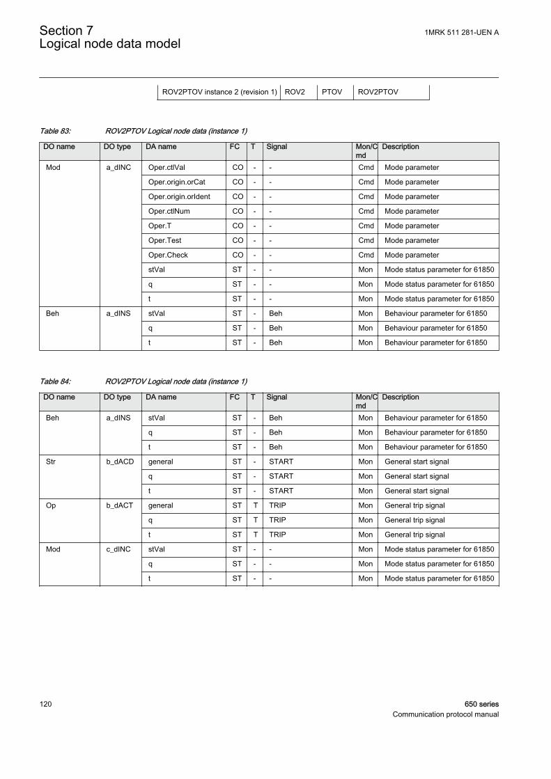
ROV2PTOV instance 2 (revision 1) ROV2 PTOV ROV2PTOV
Table 83: ROV2PTOV Logical node data (instance 1)
DO name DO type DA name FC T Signal Mon/Cmd
Description
Mod a_dINC Oper.ctlVal CO - - Cmd Mode parameter
Oper.origin.orCat CO - - Cmd Mode parameter
Oper.origin.orIdent CO - - Cmd Mode parameter
Oper.ctlNum CO - - Cmd Mode parameter
Oper.T CO - - Cmd Mode parameter
Oper.Test CO - - Cmd Mode parameter
Oper.Check CO - - Cmd Mode parameter
stVal ST - - Mon Mode status parameter for 61850
q ST - - Mon Mode status parameter for 61850
t ST - - Mon Mode status parameter for 61850
Beh a_dINS stVal ST - Beh Mon Behaviour parameter for 61850
q ST - Beh Mon Behaviour parameter for 61850
t ST - Beh Mon Behaviour parameter for 61850
Table 84: ROV2PTOV Logical node data (instance 1)
DO name DO type DA name FC T Signal Mon/Cmd
Description
Beh a_dINS stVal ST - Beh Mon Behaviour parameter for 61850
q ST - Beh Mon Behaviour parameter for 61850
t ST - Beh Mon Behaviour parameter for 61850
Str b_dACD general ST - START Mon General start signal
q ST - START Mon General start signal
t ST - START Mon General start signal
Op b_dACT general ST T TRIP Mon General trip signal
q ST T TRIP Mon General trip signal
t ST T TRIP Mon General trip signal
Mod c_dINC stVal ST - - Mon Mode status parameter for 61850
q ST - - Mon Mode status parameter for 61850
t ST - - Mon Mode status parameter for 61850
Section 7 1MRK 511 281-UEN ALogical node data model
120 650 seriesCommunication protocol manual

Table 85: ROV2PTOV Logical node data (instance 1)
DO name DO type DA name FC T Signal Mon/Cmd
Description
Beh a_dINS stVal ST - Beh Mon Behaviour parameter for 61850
q ST - Beh Mon Behaviour parameter for 61850
t ST - Beh Mon Behaviour parameter for 61850
Str b_dACD general ST - ST1 Mon Start signal from step 1
q ST - ST1 Mon Start signal from step 1
t ST - ST1 Mon Start signal from step 1
Op b_dACT general ST T TR1 Mon Trip signal from step 1
q ST T TR1 Mon Trip signal from step 1
t ST T TR1 Mon Trip signal from step 1
Mod c_dINC stVal ST - - Mon Mode status parameter for 61850
q ST - - Mon Mode status parameter for 61850
t ST - - Mon Mode status parameter for 61850
Table 86: ROV2PTOV Logical node data (instance 2)
DO name DO type DA name FC T Signal Mon/Cmd
Description
Beh a_dINS stVal ST - Beh Mon Behaviour parameter for 61850
q ST - Beh Mon Behaviour parameter for 61850
t ST - Beh Mon Behaviour parameter for 61850
Str b_dACD general ST - ST2 Mon Start signal from step 2
q ST - ST2 Mon Start signal from step 2
t ST - ST2 Mon Start signal from step 2
Op b_dACT general ST T TR2 Mon Trip signal from step 2
q ST T TR2 Mon Trip signal from step 2
t ST T TR2 Mon Trip signal from step 2
Mod c_dINC stVal ST - - Mon Mode status parameter for 61850
q ST - - Mon Mode status parameter for 61850
t ST - - Mon Mode status parameter for 61850
7.5.14 Protection trip conditioning PTRC
7.5.14.1 Tripping logic common 3-phase output SMPPTRC
LN type LN prefix LN class Function block name
SMPPTRC (revision 1) SMP PTRC SMPPTRC
1MRK 511 281-UEN A Section 7Logical node data model
650 series 121Communication protocol manual

Table 87: SMPPTRC Logical node data
DO name DO type DA name FC T Signal Mon/Cmd
Description
Mod a_dINC Oper.ctlVal CO - - Cmd Mode parameter
Oper.origin.orCat CO - - Cmd Mode parameter
Oper.origin.orIdent CO - - Cmd Mode parameter
Oper.ctlNum CO - - Cmd Mode parameter
Oper.T CO - - Cmd Mode parameter
Oper.Test CO - - Cmd Mode parameter
Oper.Check CO - - Cmd Mode parameter
stVal ST - - Mon Mode status parameter for 61850
q ST - - Mon Mode status parameter for 61850
t ST - - Mon Mode status parameter for 61850
Beh a_dINS stVal ST - Beh Mon Behaviour parameter for 61850
q ST - Beh Mon Behaviour parameter for 61850
t ST - Beh Mon Behaviour parameter for 61850
Op b_dACT general ST T TRIP Mon General trip signal
q ST T TRIP Mon General trip signal
t ST T TRIP Mon General trip signal
LORs v1_dSPC Oper.ctlVal CO - - Cmd Command parameter forIEC61850
Oper.origin.orCat CO - - Cmd Command parameter forIEC61850
Oper.origin.orIdent CO - - Cmd Command parameter forIEC61850
Oper.ctlNum CO - - Cmd Command parameter forIEC61850
Oper.T CO - - Cmd Command parameter forIEC61850
Oper.Test CO - - Cmd Command parameter forIEC61850
Oper.Check CO - - Cmd Command parameter forIEC61850
ClsLO v1_dSPS stVal ST - CLLKOUT Mon Circuit breaker lockout output (setuntil reset)
q ST - CLLKOUT Mon Circuit breaker lockout output (setuntil reset)
t ST - CLLKOUT Mon Circuit breaker lockout output (setuntil reset)
Section 7 1MRK 511 281-UEN ALogical node data model
122 650 seriesCommunication protocol manual
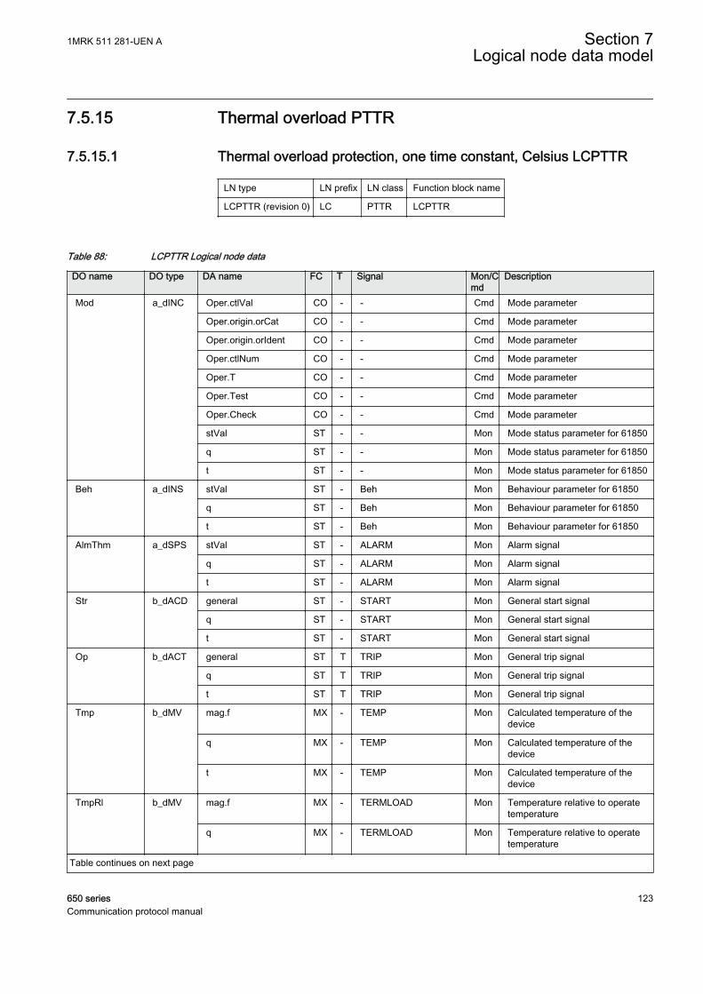
7.5.15 Thermal overload PTTR
7.5.15.1 Thermal overload protection, one time constant, Celsius LCPTTR
LN type LN prefix LN class Function block name
LCPTTR (revision 0) LC PTTR LCPTTR
Table 88: LCPTTR Logical node data
DO name DO type DA name FC T Signal Mon/Cmd
Description
Mod a_dINC Oper.ctlVal CO - - Cmd Mode parameter
Oper.origin.orCat CO - - Cmd Mode parameter
Oper.origin.orIdent CO - - Cmd Mode parameter
Oper.ctlNum CO - - Cmd Mode parameter
Oper.T CO - - Cmd Mode parameter
Oper.Test CO - - Cmd Mode parameter
Oper.Check CO - - Cmd Mode parameter
stVal ST - - Mon Mode status parameter for 61850
q ST - - Mon Mode status parameter for 61850
t ST - - Mon Mode status parameter for 61850
Beh a_dINS stVal ST - Beh Mon Behaviour parameter for 61850
q ST - Beh Mon Behaviour parameter for 61850
t ST - Beh Mon Behaviour parameter for 61850
AlmThm a_dSPS stVal ST - ALARM Mon Alarm signal
q ST - ALARM Mon Alarm signal
t ST - ALARM Mon Alarm signal
Str b_dACD general ST - START Mon General start signal
q ST - START Mon General start signal
t ST - START Mon General start signal
Op b_dACT general ST T TRIP Mon General trip signal
q ST T TRIP Mon General trip signal
t ST T TRIP Mon General trip signal
Tmp b_dMV mag.f MX - TEMP Mon Calculated temperature of thedevice
q MX - TEMP Mon Calculated temperature of thedevice
t MX - TEMP Mon Calculated temperature of thedevice
TmpRl b_dMV mag.f MX - TERMLOAD Mon Temperature relative to operatetemperature
q MX - TERMLOAD Mon Temperature relative to operatetemperature
Table continues on next page
1MRK 511 281-UEN A Section 7Logical node data model
650 series 123Communication protocol manual
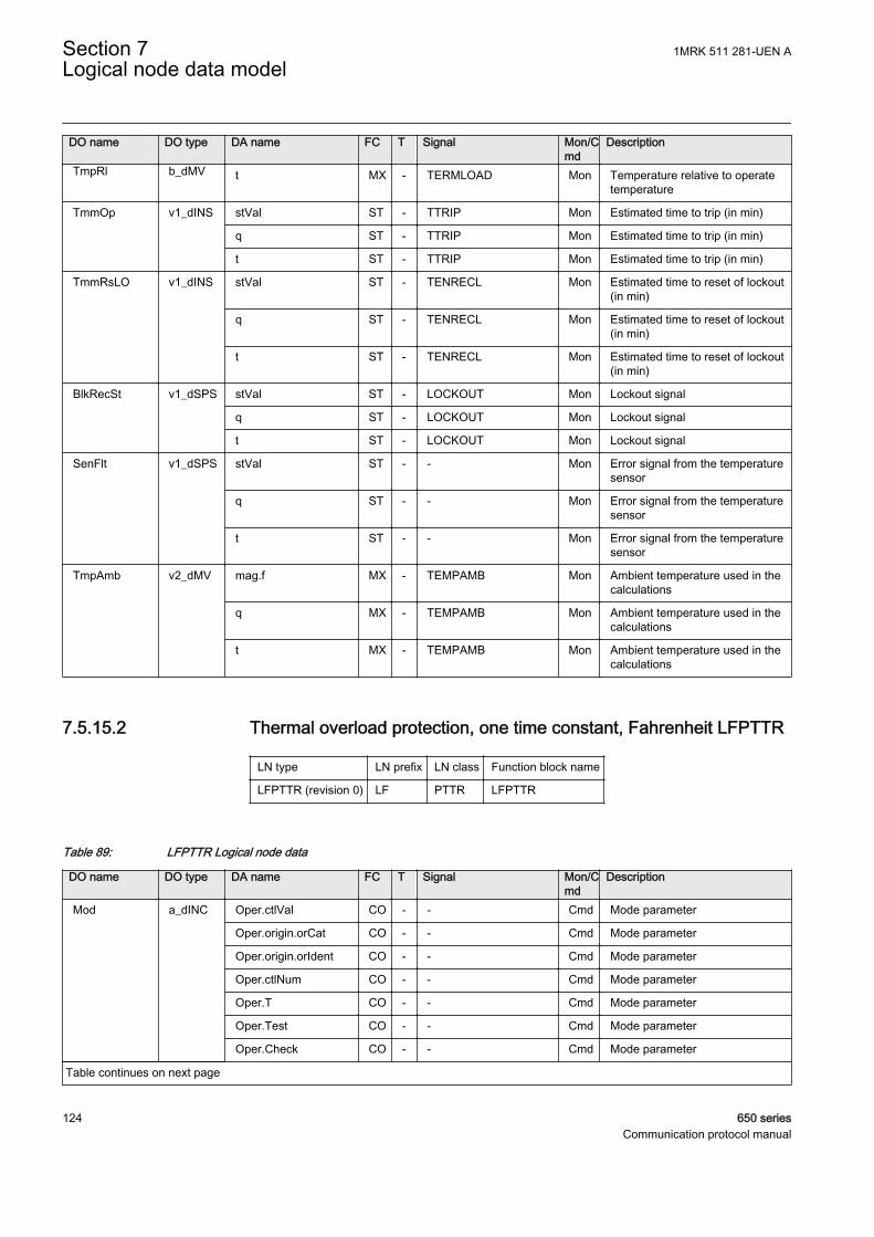
DO name DO type DA name FC T Signal Mon/Cmd
Description
TmpRl b_dMV t MX - TERMLOAD Mon Temperature relative to operatetemperature
TmmOp v1_dINS stVal ST - TTRIP Mon Estimated time to trip (in min)
q ST - TTRIP Mon Estimated time to trip (in min)
t ST - TTRIP Mon Estimated time to trip (in min)
TmmRsLO v1_dINS stVal ST - TENRECL Mon Estimated time to reset of lockout(in min)
q ST - TENRECL Mon Estimated time to reset of lockout(in min)
t ST - TENRECL Mon Estimated time to reset of lockout(in min)
BlkRecSt v1_dSPS stVal ST - LOCKOUT Mon Lockout signal
q ST - LOCKOUT Mon Lockout signal
t ST - LOCKOUT Mon Lockout signal
SenFlt v1_dSPS stVal ST - - Mon Error signal from the temperaturesensor
q ST - - Mon Error signal from the temperaturesensor
t ST - - Mon Error signal from the temperaturesensor
TmpAmb v2_dMV mag.f MX - TEMPAMB Mon Ambient temperature used in thecalculations
q MX - TEMPAMB Mon Ambient temperature used in thecalculations
t MX - TEMPAMB Mon Ambient temperature used in thecalculations
7.5.15.2 Thermal overload protection, one time constant, Fahrenheit LFPTTR
LN type LN prefix LN class Function block name
LFPTTR (revision 0) LF PTTR LFPTTR
Table 89: LFPTTR Logical node data
DO name DO type DA name FC T Signal Mon/Cmd
Description
Mod a_dINC Oper.ctlVal CO - - Cmd Mode parameter
Oper.origin.orCat CO - - Cmd Mode parameter
Oper.origin.orIdent CO - - Cmd Mode parameter
Oper.ctlNum CO - - Cmd Mode parameter
Oper.T CO - - Cmd Mode parameter
Oper.Test CO - - Cmd Mode parameter
Oper.Check CO - - Cmd Mode parameter
Table continues on next page
Section 7 1MRK 511 281-UEN ALogical node data model
124 650 seriesCommunication protocol manual

DO name DO type DA name FC T Signal Mon/Cmd
Description
Mod a_dINC stVal ST - - Mon Mode status parameter for 61850
q ST - - Mon Mode status parameter for 61850
t ST - - Mon Mode status parameter for 61850
Beh a_dINS stVal ST - Beh Mon Behaviour parameter for 61850
q ST - Beh Mon Behaviour parameter for 61850
t ST - Beh Mon Behaviour parameter for 61850
AlmThm a_dSPS stVal ST - ALARM Mon Alarm signal
q ST - ALARM Mon Alarm signal
t ST - ALARM Mon Alarm signal
Str b_dACD general ST - START Mon General start signal
q ST - START Mon General start signal
t ST - START Mon General start signal
Op b_dACT general ST T TRIP Mon General trip signal
q ST T TRIP Mon General trip signal
t ST T TRIP Mon General trip signal
Tmp b_dMV mag.f MX - TEMP Mon Calculated temperature of thedevice
q MX - TEMP Mon Calculated temperature of thedevice
t MX - TEMP Mon Calculated temperature of thedevice
TmpRl b_dMV mag.f MX - TERMLOAD Mon Temperature relative to operatetemperature
q MX - TERMLOAD Mon Temperature relative to operatetemperature
t MX - TERMLOAD Mon Temperature relative to operatetemperature
TmmOp v1_dINS stVal ST - TTRIP Mon Estimated time to trip (in min)
q ST - TTRIP Mon Estimated time to trip (in min)
t ST - TTRIP Mon Estimated time to trip (in min)
TmmRsLO v1_dINS stVal ST - TENRECL Mon Estimated time to reset of lockout(in min)
q ST - TENRECL Mon Estimated time to reset of lockout(in min)
t ST - TENRECL Mon Estimated time to reset of lockout(in min)
BlkRecSt v1_dSPS stVal ST - LOCKOUT Mon Lockout signal
q ST - LOCKOUT Mon Lockout signal
t ST - LOCKOUT Mon Lockout signal
SenFlt v1_dSPS stVal ST - - Mon Error signal from the temperaturesensor
q ST - - Mon Error signal from the temperaturesensor
Table continues on next page
1MRK 511 281-UEN A Section 7Logical node data model
650 series 125Communication protocol manual
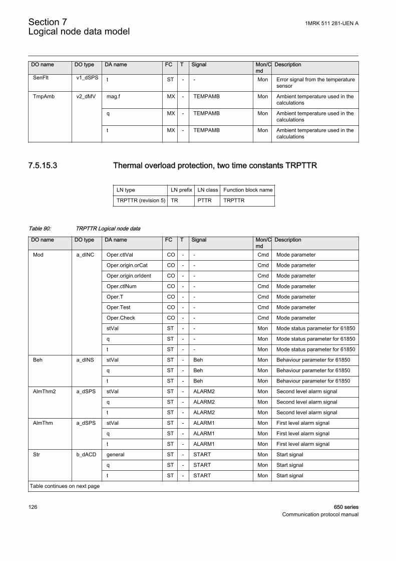
DO name DO type DA name FC T Signal Mon/Cmd
Description
SenFlt v1_dSPS t ST - - Mon Error signal from the temperaturesensor
TmpAmb v2_dMV mag.f MX - TEMPAMB Mon Ambient temperature used in thecalculations
q MX - TEMPAMB Mon Ambient temperature used in thecalculations
t MX - TEMPAMB Mon Ambient temperature used in thecalculations
7.5.15.3 Thermal overload protection, two time constants TRPTTR
LN type LN prefix LN class Function block name
TRPTTR (revision 5) TR PTTR TRPTTR
Table 90: TRPTTR Logical node data
DO name DO type DA name FC T Signal Mon/Cmd
Description
Mod a_dINC Oper.ctlVal CO - - Cmd Mode parameter
Oper.origin.orCat CO - - Cmd Mode parameter
Oper.origin.orIdent CO - - Cmd Mode parameter
Oper.ctlNum CO - - Cmd Mode parameter
Oper.T CO - - Cmd Mode parameter
Oper.Test CO - - Cmd Mode parameter
Oper.Check CO - - Cmd Mode parameter
stVal ST - - Mon Mode status parameter for 61850
q ST - - Mon Mode status parameter for 61850
t ST - - Mon Mode status parameter for 61850
Beh a_dINS stVal ST - Beh Mon Behaviour parameter for 61850
q ST - Beh Mon Behaviour parameter for 61850
t ST - Beh Mon Behaviour parameter for 61850
AlmThm2 a_dSPS stVal ST - ALARM2 Mon Second level alarm signal
q ST - ALARM2 Mon Second level alarm signal
t ST - ALARM2 Mon Second level alarm signal
AlmThm a_dSPS stVal ST - ALARM1 Mon First level alarm signal
q ST - ALARM1 Mon First level alarm signal
t ST - ALARM1 Mon First level alarm signal
Str b_dACD general ST - START Mon Start signal
q ST - START Mon Start signal
t ST - START Mon Start signal
Table continues on next page
Section 7 1MRK 511 281-UEN ALogical node data model
126 650 seriesCommunication protocol manual

DO name DO type DA name FC T Signal Mon/Cmd
Description
Op b_dACT general ST T TRIP Mon Trip Signal
q ST T TRIP Mon Trip Signal
t ST T TRIP Mon Trip Signal
LO v1_dSPS stVal ST - LOCKOUT Mon Lockout signal
q ST - LOCKOUT Mon Lockout signal
t ST - LOCKOUT Mon Lockout signal
Wrn v1_dSPS stVal ST - WARNING Mon Trip within set warning time
q ST - WARNING Mon Trip within set warning time
t ST - WARNING Mon Trip within set warning time
TmmOp v2_dMV mag.f MX - TTRIP Mon Estimated time to trip (in min)
q MX - TTRIP Mon Estimated time to trip (in min)
t MX - TTRIP Mon Estimated time to trip (in min)
TmmRsLO v2_dMV mag.f MX - TRESLO Mon Estimated time to reset of thefunction (in min)
q MX - TRESLO Mon Estimated time to reset of thefunction (in min)
t MX - TRESLO Mon Estimated time to reset of thefunction (in min)
AClcPct v2_dMV mag.f MX - I-MEASUR Mon Current measured by the functionin % of the rated current
q MX - I-MEASUR Mon Current measured by the functionin % of the rated current
t MX - I-MEASUR Mon Current measured by the functionin % of the rated current
TmpPct v2_dMV mag.f MX - HEATCONT Mon Percentage of the heat content ofthe transformer
q MX - HEATCONT Mon Percentage of the heat content ofthe transformer
t MX - HEATCONT Mon Percentage of the heat content ofthe transformer
7.5.16 Time undercurrent PTUC
7.5.16.1 Time delayed 2-step undercurrent protection UC2PTUC
LN type LN prefix LN class Function block name
PH3PTRC instance 1 (revision 1) PH3 PTRC UC2PTUC
PH3PTUC instance 1 (revision 0) PH3 PTUC UC2PTUC
PH3PTUC instance 2 (revision 0) PH3 PTUC UC2PTUC
UC2LLN0 instance 1 (revision 0) - LLN0 UC2PTUC
1MRK 511 281-UEN A Section 7Logical node data model
650 series 127Communication protocol manual
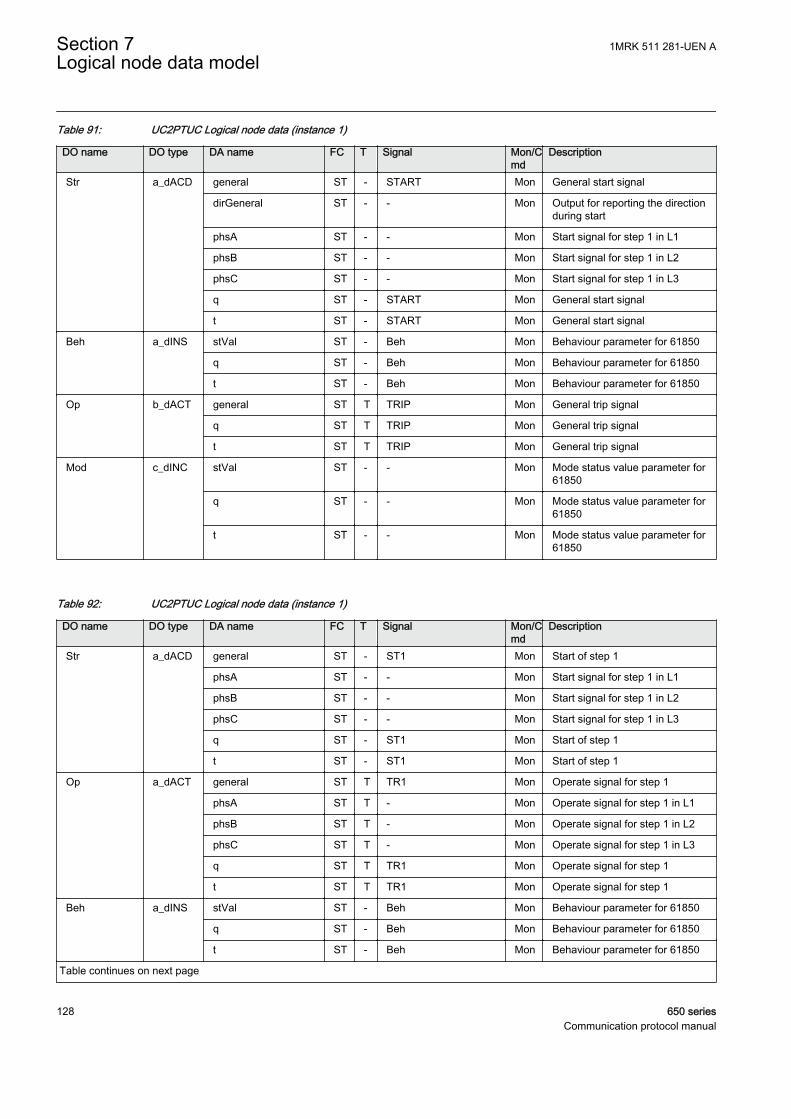
Table 91: UC2PTUC Logical node data (instance 1)
DO name DO type DA name FC T Signal Mon/Cmd
Description
Str a_dACD general ST - START Mon General start signal
dirGeneral ST - - Mon Output for reporting the directionduring start
phsA ST - - Mon Start signal for step 1 in L1
phsB ST - - Mon Start signal for step 1 in L2
phsC ST - - Mon Start signal for step 1 in L3
q ST - START Mon General start signal
t ST - START Mon General start signal
Beh a_dINS stVal ST - Beh Mon Behaviour parameter for 61850
q ST - Beh Mon Behaviour parameter for 61850
t ST - Beh Mon Behaviour parameter for 61850
Op b_dACT general ST T TRIP Mon General trip signal
q ST T TRIP Mon General trip signal
t ST T TRIP Mon General trip signal
Mod c_dINC stVal ST - - Mon Mode status value parameter for61850
q ST - - Mon Mode status value parameter for61850
t ST - - Mon Mode status value parameter for61850
Table 92: UC2PTUC Logical node data (instance 1)
DO name DO type DA name FC T Signal Mon/Cmd
Description
Str a_dACD general ST - ST1 Mon Start of step 1
phsA ST - - Mon Start signal for step 1 in L1
phsB ST - - Mon Start signal for step 1 in L2
phsC ST - - Mon Start signal for step 1 in L3
q ST - ST1 Mon Start of step 1
t ST - ST1 Mon Start of step 1
Op a_dACT general ST T TR1 Mon Operate signal for step 1
phsA ST T - Mon Operate signal for step 1 in L1
phsB ST T - Mon Operate signal for step 1 in L2
phsC ST T - Mon Operate signal for step 1 in L3
q ST T TR1 Mon Operate signal for step 1
t ST T TR1 Mon Operate signal for step 1
Beh a_dINS stVal ST - Beh Mon Behaviour parameter for 61850
q ST - Beh Mon Behaviour parameter for 61850
t ST - Beh Mon Behaviour parameter for 61850
Table continues on next page
Section 7 1MRK 511 281-UEN ALogical node data model
128 650 seriesCommunication protocol manual

DO name DO type DA name FC T Signal Mon/Cmd
Description
Mod c_dINC stVal ST - - Mon Mode status value parameter for61850
q ST - - Mon Mode status value parameter for61850
t ST - - Mon Mode status value parameter for61850
Table 93: UC2PTUC Logical node data (instance 2)
DO name DO type DA name FC T Signal Mon/Cmd
Description
Str a_dACD general ST - ST2 Mon Start of step 2
phsA ST - - Mon Start signal for step 2 in L1
phsB ST - - Mon Start signal for step 2 in L2
phsC ST - - Mon Start signal for step 2 in L3
q ST - ST2 Mon Start of step 2
t ST - ST2 Mon Start of step 2
Op a_dACT general ST T TR2 Mon Operate signal for step 2
phsA ST T - Mon Operate signal for step 2 in L1
phsB ST T - Mon Operate signal for step 2 in L2
phsC ST T - Mon Operate signal for step 2 in L3
q ST T TR2 Mon Operate signal for step 2
t ST T TR2 Mon Operate signal for step 2
Beh a_dINS stVal ST - Beh Mon Behaviour parameter for 61850
q ST - Beh Mon Behaviour parameter for 61850
t ST - Beh Mon Behaviour parameter for 61850
Mod c_dINC stVal ST - - Mon Mode status value parameter for61850
q ST - - Mon Mode status value parameter for61850
t ST - - Mon Mode status value parameter for61850
Table 94: UC2PTUC Logical node data (instance 1)
DO name DO type DA name FC T Signal Mon/Cmd
Description
Mod a_dINC Oper.ctlVal CO - - Cmd Mode parameter for 61850
Oper.origin.orCat CO - - Cmd Mode parameter for 61850
Oper.origin.orIdent CO - - Cmd Mode parameter for 61850
Oper.ctlNum CO - - Cmd Mode parameter for 61850
Oper.T CO - - Cmd Mode parameter for 61850
Oper.Test CO - - Cmd Mode parameter for 61850
Table continues on next page
1MRK 511 281-UEN A Section 7Logical node data model
650 series 129Communication protocol manual

DO name DO type DA name FC T Signal Mon/Cmd
Description
Mod a_dINC Oper.Check CO - - Cmd Mode parameter for 61850
stVal ST - - Mon Mode status value parameter for61850
q ST - - Mon Mode status value parameter for61850
t ST - - Mon Mode status value parameter for61850
Beh a_dINS stVal ST - Beh Mon Behaviour parameter for 61850
q ST - Beh Mon Behaviour parameter for 61850
t ST - Beh Mon Behaviour parameter for 61850
7.5.17 Undervoltage PTUV
7.5.17.1 Two step undervoltage protection UV2PTUV
LN type LN prefix LN class Function block name
GEN2LLN0 instance 1 (revision 1) - LLN0 UV2PTUV
PH3PTRC instance 1 (revision 1) PH3 PTRC UV2PTUV
UV2PTUV instance 1 (revision 1) UV2 PTUV UV2PTUV
UV2PTUV instance 2 (revision 1) UV2 PTUV UV2PTUV
Table 95: UV2PTUV Logical node data (instance 1)
DO name DO type DA name FC T Signal Mon/Cmd
Description
Mod a_dINC Oper.ctlVal CO - - Cmd Mode parameter
Oper.origin.orCat CO - - Cmd Mode parameter
Oper.origin.orIdent CO - - Cmd Mode parameter
Oper.ctlNum CO - - Cmd Mode parameter
Oper.T CO - - Cmd Mode parameter
Oper.Test CO - - Cmd Mode parameter
Oper.Check CO - - Cmd Mode parameter
stVal ST - - Mon Mode status parameter for 61850
q ST - - Mon Mode status parameter for 61850
t ST - - Mon Mode status parameter for 61850
Beh a_dINS stVal ST - Beh Mon Behaviour parameter for 61850
q ST - Beh Mon Behaviour parameter for 61850
t ST - Beh Mon Behaviour parameter for 61850
Section 7 1MRK 511 281-UEN ALogical node data model
130 650 seriesCommunication protocol manual
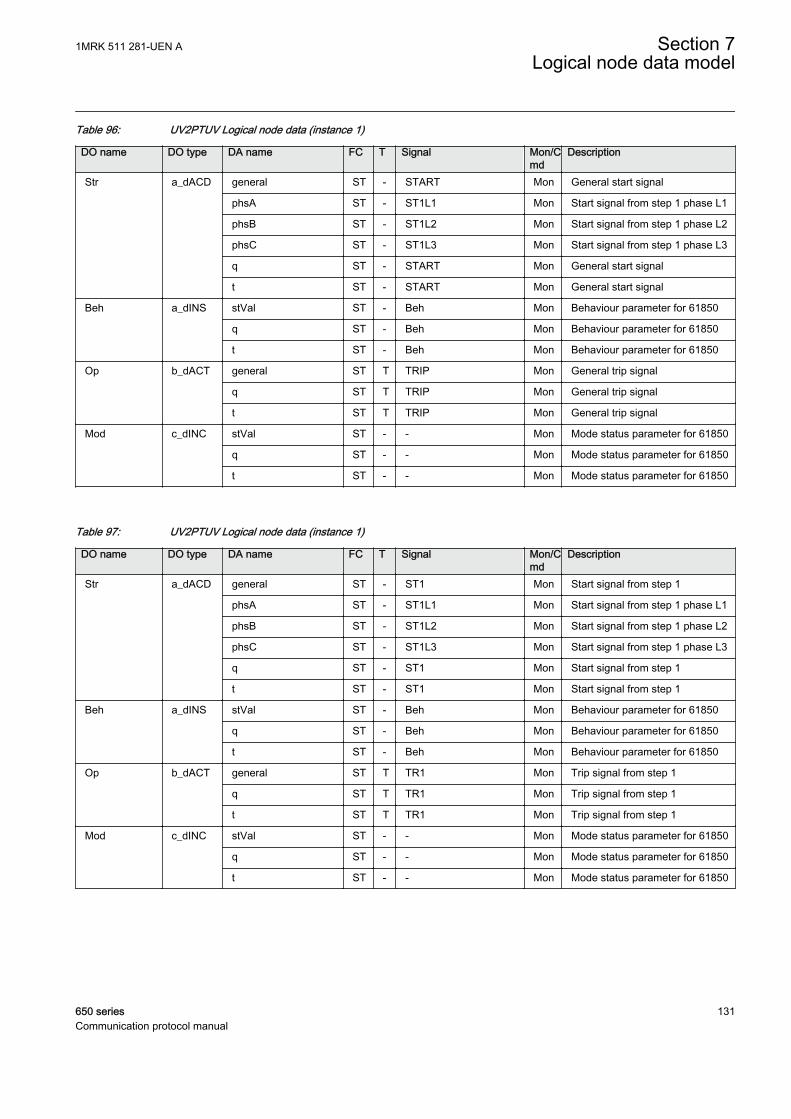
Table 96: UV2PTUV Logical node data (instance 1)
DO name DO type DA name FC T Signal Mon/Cmd
Description
Str a_dACD general ST - START Mon General start signal
phsA ST - ST1L1 Mon Start signal from step 1 phase L1
phsB ST - ST1L2 Mon Start signal from step 1 phase L2
phsC ST - ST1L3 Mon Start signal from step 1 phase L3
q ST - START Mon General start signal
t ST - START Mon General start signal
Beh a_dINS stVal ST - Beh Mon Behaviour parameter for 61850
q ST - Beh Mon Behaviour parameter for 61850
t ST - Beh Mon Behaviour parameter for 61850
Op b_dACT general ST T TRIP Mon General trip signal
q ST T TRIP Mon General trip signal
t ST T TRIP Mon General trip signal
Mod c_dINC stVal ST - - Mon Mode status parameter for 61850
q ST - - Mon Mode status parameter for 61850
t ST - - Mon Mode status parameter for 61850
Table 97: UV2PTUV Logical node data (instance 1)
DO name DO type DA name FC T Signal Mon/Cmd
Description
Str a_dACD general ST - ST1 Mon Start signal from step 1
phsA ST - ST1L1 Mon Start signal from step 1 phase L1
phsB ST - ST1L2 Mon Start signal from step 1 phase L2
phsC ST - ST1L3 Mon Start signal from step 1 phase L3
q ST - ST1 Mon Start signal from step 1
t ST - ST1 Mon Start signal from step 1
Beh a_dINS stVal ST - Beh Mon Behaviour parameter for 61850
q ST - Beh Mon Behaviour parameter for 61850
t ST - Beh Mon Behaviour parameter for 61850
Op b_dACT general ST T TR1 Mon Trip signal from step 1
q ST T TR1 Mon Trip signal from step 1
t ST T TR1 Mon Trip signal from step 1
Mod c_dINC stVal ST - - Mon Mode status parameter for 61850
q ST - - Mon Mode status parameter for 61850
t ST - - Mon Mode status parameter for 61850
1MRK 511 281-UEN A Section 7Logical node data model
650 series 131Communication protocol manual

Table 98: UV2PTUV Logical node data (instance 2)
DO name DO type DA name FC T Signal Mon/Cmd
Description
Str a_dACD general ST - ST2 Mon Start signal from step 2
phsA ST - - Mon Start signal from step2 phase L1
phsB ST - - Mon Start signal from step2 phase L2
phsC ST - - Mon Start signal from step2 phase L3
q ST - ST2 Mon Start signal from step 2
t ST - ST2 Mon Start signal from step 2
Beh a_dINS stVal ST - Beh Mon Behaviour parameter for 61850
q ST - Beh Mon Behaviour parameter for 61850
t ST - Beh Mon Behaviour parameter for 61850
Op b_dACT general ST T TR2 Mon Trip signal from step 2
q ST T TR2 Mon Trip signal from step 2
t ST T TR2 Mon Trip signal from step 2
Mod c_dINC stVal ST - - Mon Mode status parameter for 61850
q ST - - Mon Mode status parameter for 61850
t ST - - Mon Mode status parameter for 61850
7.5.17.2 Loss of voltage check LOVPTUV
LN type LN prefix LN class Function block name
LOVPTUV (revision 1) LOV PTUV LOVPTUV
Table 99: LOVPTUV Logical node data
DO name DO type DA name FC T Signal Mon/Cmd
Description
Mod a_dINC Oper.ctlVal CO - - Cmd Mode parameter for 61850
Oper.origin.orCat CO - - Cmd Mode parameter for 61850
Oper.origin.orIdent CO - - Cmd Mode parameter for 61850
Oper.ctlNum CO - - Cmd Mode parameter for 61850
Oper.T CO - - Cmd Mode parameter for 61850
Oper.Test CO - - Cmd Mode parameter for 61850
Oper.Check CO - - Cmd Mode parameter for 61850
stVal ST - - Mon Mode status parameter for 61850
q ST - - Mon Mode status parameter for 61850
t ST - - Mon Mode status parameter for 61850
Beh a_dINS stVal ST - Beh Mon Behaviour parameter for 61850
q ST - Beh Mon Behaviour parameter for 61850
t ST - Beh Mon Behaviour parameter for 61850
Table continues on next page
Section 7 1MRK 511 281-UEN ALogical node data model
132 650 seriesCommunication protocol manual
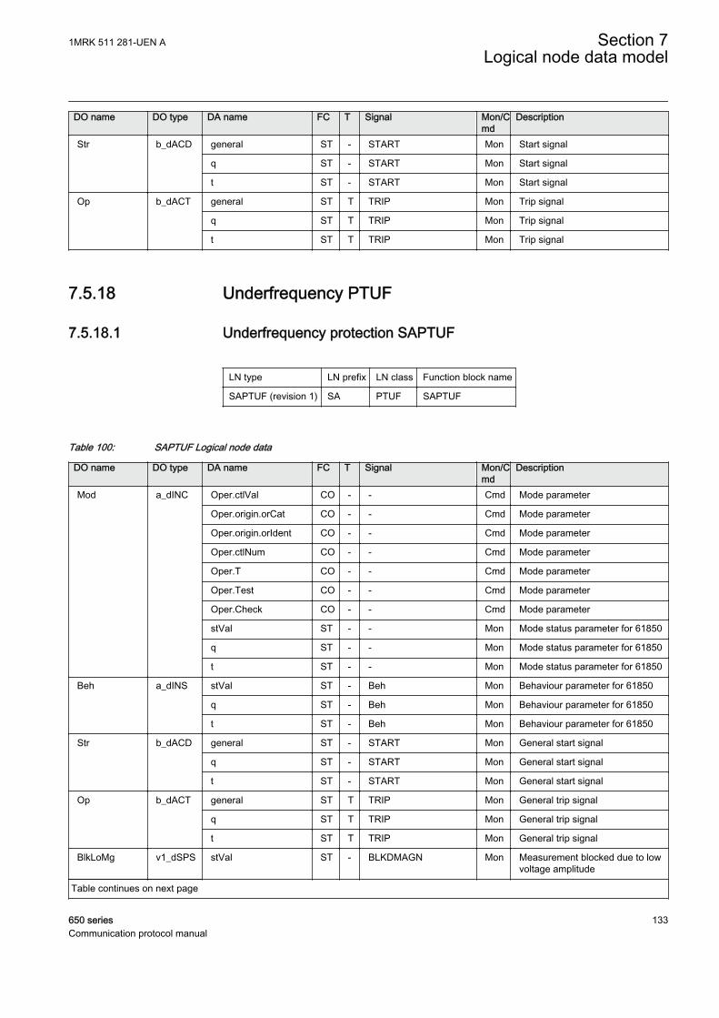
DO name DO type DA name FC T Signal Mon/Cmd
Description
Str b_dACD general ST - START Mon Start signal
q ST - START Mon Start signal
t ST - START Mon Start signal
Op b_dACT general ST T TRIP Mon Trip signal
q ST T TRIP Mon Trip signal
t ST T TRIP Mon Trip signal
7.5.18 Underfrequency PTUF
7.5.18.1 Underfrequency protection SAPTUF
LN type LN prefix LN class Function block name
SAPTUF (revision 1) SA PTUF SAPTUF
Table 100: SAPTUF Logical node data
DO name DO type DA name FC T Signal Mon/Cmd
Description
Mod a_dINC Oper.ctlVal CO - - Cmd Mode parameter
Oper.origin.orCat CO - - Cmd Mode parameter
Oper.origin.orIdent CO - - Cmd Mode parameter
Oper.ctlNum CO - - Cmd Mode parameter
Oper.T CO - - Cmd Mode parameter
Oper.Test CO - - Cmd Mode parameter
Oper.Check CO - - Cmd Mode parameter
stVal ST - - Mon Mode status parameter for 61850
q ST - - Mon Mode status parameter for 61850
t ST - - Mon Mode status parameter for 61850
Beh a_dINS stVal ST - Beh Mon Behaviour parameter for 61850
q ST - Beh Mon Behaviour parameter for 61850
t ST - Beh Mon Behaviour parameter for 61850
Str b_dACD general ST - START Mon General start signal
q ST - START Mon General start signal
t ST - START Mon General start signal
Op b_dACT general ST T TRIP Mon General trip signal
q ST T TRIP Mon General trip signal
t ST T TRIP Mon General trip signal
BlkLoMg v1_dSPS stVal ST - BLKDMAGN Mon Measurement blocked due to lowvoltage amplitude
Table continues on next page
1MRK 511 281-UEN A Section 7Logical node data model
650 series 133Communication protocol manual

DO name DO type DA name FC T Signal Mon/Cmd
Description
BlkLoMg v1_dSPS q ST - BLKDMAGN Mon Measurement blocked due to lowvoltage amplitude
t ST - BLKDMAGN Mon Measurement blocked due to lowvoltage amplitude
RstLd v1_dSPS stVal ST - RESTORE Mon Restore signal for load restoringpurposes
q ST - RESTORE Mon Restore signal for load restoringpurposes
t ST - RESTORE Mon Restore signal for load restoringpurposes
7.5.19 Volts per Hz PVPH
7.5.19.1 Overexcitation protection OEXPVPH
LN type LN prefix LN class Function block name
OEXPVPH (revision 3) OEX PVPH OEXPVPH
Table 101: OEXPVPH Logical node data
DO name DO type DA name FC T Signal Mon/Cmd
Description
Mod a_dINC Oper.ctlVal CO - - Cmd Mode parameter for 61850
Oper.origin.orCat CO - - Cmd Mode parameter for 61850
Oper.origin.orIdent CO - - Cmd Mode parameter for 61850
Oper.ctlNum CO - - Cmd Mode parameter for 61850
Oper.T CO - - Cmd Mode parameter for 61850
Oper.Test CO - - Cmd Mode parameter for 61850
Oper.Check CO - - Cmd Mode parameter for 61850
stVal ST - - Mon Mode parameter for 61850
q ST - - Mon Mode parameter for 61850
t ST - - Mon Mode parameter for 61850
Beh a_dINS stVal ST - Beh Mon Behaviour parameter for 61850
q ST - Beh Mon Behaviour parameter for 61850
t ST - Beh Mon Behaviour parameter for 61850
Str b_dACD general ST - START Mon General start signal
q ST - START Mon General start signal
t ST - START Mon General start signal
Op b_dACT general ST T TRIP Mon General trip signal
q ST T TRIP Mon General trip signal
t ST T TRIP Mon General trip signal
Table continues on next page
Section 7 1MRK 511 281-UEN ALogical node data model
134 650 seriesCommunication protocol manual
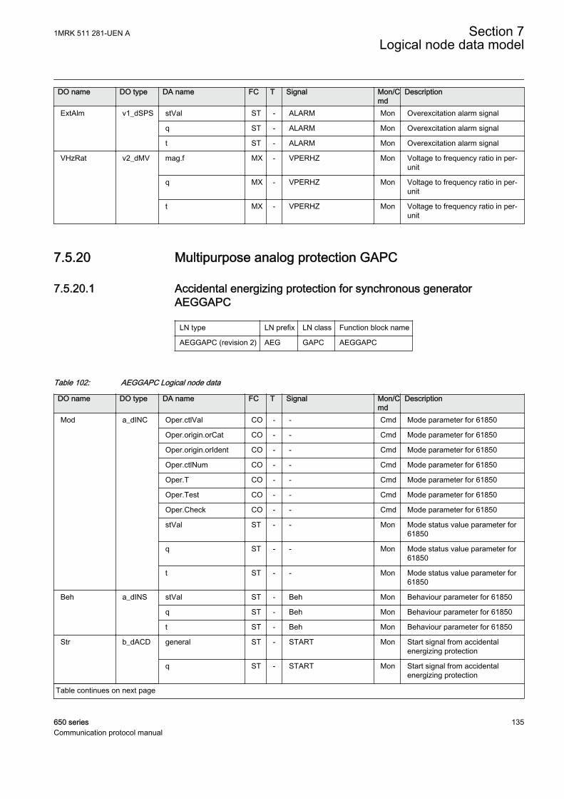
DO name DO type DA name FC T Signal Mon/Cmd
Description
ExtAlm v1_dSPS stVal ST - ALARM Mon Overexcitation alarm signal
q ST - ALARM Mon Overexcitation alarm signal
t ST - ALARM Mon Overexcitation alarm signal
VHzRat v2_dMV mag.f MX - VPERHZ Mon Voltage to frequency ratio in per-unit
q MX - VPERHZ Mon Voltage to frequency ratio in per-unit
t MX - VPERHZ Mon Voltage to frequency ratio in per-unit
7.5.20 Multipurpose analog protection GAPC
7.5.20.1 Accidental energizing protection for synchronous generatorAEGGAPC
LN type LN prefix LN class Function block name
AEGGAPC (revision 2) AEG GAPC AEGGAPC
Table 102: AEGGAPC Logical node data
DO name DO type DA name FC T Signal Mon/Cmd
Description
Mod a_dINC Oper.ctlVal CO - - Cmd Mode parameter for 61850
Oper.origin.orCat CO - - Cmd Mode parameter for 61850
Oper.origin.orIdent CO - - Cmd Mode parameter for 61850
Oper.ctlNum CO - - Cmd Mode parameter for 61850
Oper.T CO - - Cmd Mode parameter for 61850
Oper.Test CO - - Cmd Mode parameter for 61850
Oper.Check CO - - Cmd Mode parameter for 61850
stVal ST - - Mon Mode status value parameter for61850
q ST - - Mon Mode status value parameter for61850
t ST - - Mon Mode status value parameter for61850
Beh a_dINS stVal ST - Beh Mon Behaviour parameter for 61850
q ST - Beh Mon Behaviour parameter for 61850
t ST - Beh Mon Behaviour parameter for 61850
Str b_dACD general ST - START Mon Start signal from accidentalenergizing protection
q ST - START Mon Start signal from accidentalenergizing protection
Table continues on next page
1MRK 511 281-UEN A Section 7Logical node data model
650 series 135Communication protocol manual

DO name DO type DA name FC T Signal Mon/Cmd
Description
Str b_dACD t ST - START Mon Start signal from accidentalenergizing protection
Op b_dACT general ST T TRIP Mon Trip signal from accidentalenergizing protection
q ST T TRIP Mon Trip signal from accidentalenergizing protection
t ST T TRIP Mon Trip signal from accidentalenergizing protection
Armed v1_dSPS stVal ST - ARMED Mon True when accidental energizingprotection is armed
q ST - ARMED Mon True when accidental energizingprotection is armed
t ST - ARMED Mon True when accidental energizingprotection is armed
7.5.21 Out-of-step protection PPAM
7.5.21.1 Out-of-step protection OOSPPAM
LN type LN prefix LN class Function block name
OOSPPAM (revision 1) OOS PPAM OOSPPAM
Table 103: OOSPPAM Logical node data
DO name DO type DA name FC T Signal Mon/Cmd
Description
Mod a_dINC Oper.ctlVal CO - - Cmd Mode parameter for 61850
Oper.origin.orCat CO - - Cmd Mode parameter for 61850
Oper.origin.orIdent CO - - Cmd Mode parameter for 61850
Oper.ctlNum CO - - Cmd Mode parameter for 61850
Oper.T CO - - Cmd Mode parameter for 61850
Oper.Test CO - - Cmd Mode parameter for 61850
Oper.Check CO - - Cmd Mode parameter for 61850
stVal ST - - Mon Mode status value parameter for61850
q ST - - Mon Mode status value parameter for61850
t ST - - Mon Mode status value parameter for61850
Beh a_dINS stVal ST - Beh Mon Behaviour parameter for 61850
q ST - Beh Mon Behaviour parameter for 61850
t ST - Beh Mon Behaviour parameter for 61850
Table continues on next page
Section 7 1MRK 511 281-UEN ALogical node data model
136 650 seriesCommunication protocol manual
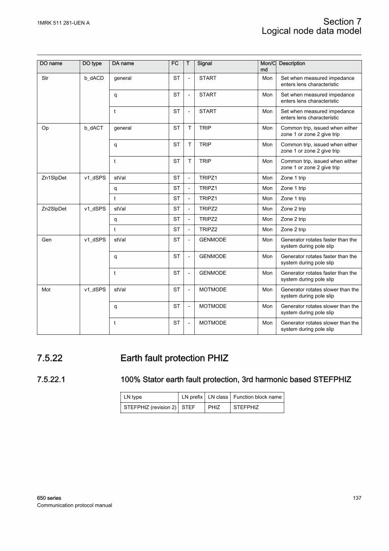
DO name DO type DA name FC T Signal Mon/Cmd
Description
Str b_dACD general ST - START Mon Set when measured impedanceenters lens characteristic
q ST - START Mon Set when measured impedanceenters lens characteristic
t ST - START Mon Set when measured impedanceenters lens characteristic
Op b_dACT general ST T TRIP Mon Common trip, issued when eitherzone 1 or zone 2 give trip
q ST T TRIP Mon Common trip, issued when eitherzone 1 or zone 2 give trip
t ST T TRIP Mon Common trip, issued when eitherzone 1 or zone 2 give trip
Zn1SlpDet v1_dSPS stVal ST - TRIPZ1 Mon Zone 1 trip
q ST - TRIPZ1 Mon Zone 1 trip
t ST - TRIPZ1 Mon Zone 1 trip
Zn2SlpDet v1_dSPS stVal ST - TRIPZ2 Mon Zone 2 trip
q ST - TRIPZ2 Mon Zone 2 trip
t ST - TRIPZ2 Mon Zone 2 trip
Gen v1_dSPS stVal ST - GENMODE Mon Generator rotates faster than thesystem during pole slip
q ST - GENMODE Mon Generator rotates faster than thesystem during pole slip
t ST - GENMODE Mon Generator rotates faster than thesystem during pole slip
Mot v1_dSPS stVal ST - MOTMODE Mon Generator rotates slower than thesystem during pole slip
q ST - MOTMODE Mon Generator rotates slower than thesystem during pole slip
t ST - MOTMODE Mon Generator rotates slower than thesystem during pole slip
7.5.22 Earth fault protection PHIZ
7.5.22.1 100% Stator earth fault protection, 3rd harmonic based STEFPHIZ
LN type LN prefix LN class Function block name
STEFPHIZ (revision 2) STEF PHIZ STEFPHIZ
1MRK 511 281-UEN A Section 7Logical node data model
650 series 137Communication protocol manual
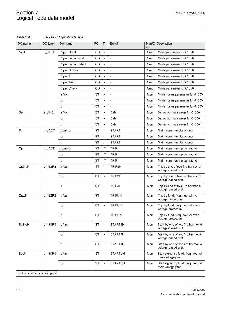
Table 104: STEFPHIZ Logical node data
DO name DO type DA name FC T Signal Mon/Cmd
Description
Mod a_dINC Oper.ctlVal CO - - Cmd Mode parameter for 61850
Oper.origin.orCat CO - - Cmd Mode parameter for 61850
Oper.origin.orIdent CO - - Cmd Mode parameter for 61850
Oper.ctlNum CO - - Cmd Mode parameter for 61850
Oper.T CO - - Cmd Mode parameter for 61850
Oper.Test CO - - Cmd Mode parameter for 61850
Oper.Check CO - - Cmd Mode parameter for 61850
stVal ST - - Mon Mode status parameter for 61850
q ST - - Mon Mode status parameter for 61850
t ST - - Mon Mode status parameter for 61850
Beh a_dINS stVal ST - Beh Mon Behaviour parameter for 61850
q ST - Beh Mon Behaviour parameter for 61850
t ST - Beh Mon Behaviour parameter for 61850
Str b_dACD general ST - START Mon Main, common start signal
q ST - START Mon Main, common start signal
t ST - START Mon Main, common start signal
Op b_dACT general ST T TRIP Mon Main, common trip command
q ST T TRIP Mon Main, common trip command
t ST T TRIP Mon Main, common trip command
Op3rdH v1_dSPS stVal ST - TRIP3H Mon Trip by one of two 3rd harmonicvoltage-based prot.
q ST - TRIP3H Mon Trip by one of two 3rd harmonicvoltage-based prot.
t ST - TRIP3H Mon Trip by one of two 3rd harmonicvoltage-based prot.
OpUN v1_dSPS stVal ST - TRIPUN Mon Trip by fund. freq. neutral over-voltage protection
q ST - TRIPUN Mon Trip by fund. freq. neutral over-voltage protection
t ST - TRIPUN Mon Trip by fund. freq. neutral over-voltage protection
Str3rdH v1_dSPS stVal ST - START3H Mon Start by one of two 3rd harmonicvoltage-based prot.
q ST - START3H Mon Start by one of two 3rd harmonicvoltage-based prot.
t ST - START3H Mon Start by one of two 3rd harmonicvoltage-based prot.
StrUN v1_dSPS stVal ST - STARTUN Mon Start signal by fund. freq. neutralover-voltage prot.
q ST - STARTUN Mon Start signal by fund. freq. neutralover-voltage prot.
Table continues on next page
Section 7 1MRK 511 281-UEN ALogical node data model
138 650 seriesCommunication protocol manual

DO name DO type DA name FC T Signal Mon/Cmd
Description
StrUN v1_dSPS t ST - STARTUN Mon Start signal by fund. freq. neutralover-voltage prot.
VT3rdH v2_dMV mag.f MX - UT3 Mon Mag. of 3rd harm. voltage atgenerator terminal side
q MX - UT3 Mon Mag. of 3rd harm. voltage atgenerator terminal side
t MX - UT3 Mon Mag. of 3rd harm. voltage atgenerator terminal side
VN3rdH v2_dMV mag.f MX - UN3 Mon Mag. of 3rd harm. voltage atgenerator neutral side
q MX - UN3 Mon Mag. of 3rd harm. voltage atgenerator neutral side
t MX - UN3 Mon Mag. of 3rd harm. voltage atgenerator neutral side
E3 v2_dMV mag.f MX - E3 Mon Total induced stator 3rd harmonicvoltage
q MX - E3 Mon Total induced stator 3rd harmonicvoltage
t MX - E3 Mon Total induced stator 3rd harmonicvoltage
VDif3rdH v2_dMV mag.f MX - DU3 Mon Diff. between 3rd harm. volt. atboth sides of gen.
q MX - DU3 Mon Diff. between 3rd harm. volt. atboth sides of gen.
t MX - DU3 Mon Diff. between 3rd harm. volt. atboth sides of gen.
VBias3rdH v2_dMV mag.f MX - BU3 Mon Bias voltage, a part of UN3
q MX - BU3 Mon Bias voltage, a part of UN3
t MX - BU3 Mon Bias voltage, a part of UN3
UN v2_dMV mag.f MX - UN Mon Fund. frequency voltage atgenerator neutral
q MX - UN Mon Fund. frequency voltage atgenerator neutral
t MX - UN Mon Fund. frequency voltage atgenerator neutral
VolAngClc v2_dMV mag.f MX - ANGLE Mon Angle between 3rd harmonicvotage phasors
q MX - ANGLE Mon Angle between 3rd harmonicvotage phasors
t MX - ANGLE Mon Angle between 3rd harmonicvotage phasors
1MRK 511 281-UEN A Section 7Logical node data model
650 series 139Communication protocol manual

7.5.23 Voltage-restrained time overcurrent PVOC
7.5.23.1 Voltage-restrained time overcurrent protection VRPVOC
LN type LN prefix LN class Function block name
PH1PTRC instance 1 (revision 2) PH1 PTRC VRPVOC
PH1PTUV instance 1 (revision 0) PH1 PTUV VRPVOC
VRLLN0 instance 1 (revision 0) - LLN0 VRPVOC
VRPVOC instance 1 (revision 0) VR PVOC VRPVOC
Table 105: VRPVOC Logical node data (instance 1)
DO name DO type DA name FC T Signal Mon/Cmd
Description
Beh a_dINS stVal ST - Beh Mon Behaviour parameter for 61850
q ST - Beh Mon Behaviour parameter for 61850
t ST - Beh Mon Behaviour parameter for 61850
Str b_dACD general ST - START Mon General start signal
q ST - START Mon General start signal
t ST - START Mon General start signal
Op b_dACT general ST - TRIP Mon General trip signal
q ST - TRIP Mon General trip signal
t ST - TRIP Mon General trip signal
Mod c_dINC stVal ST - - Mon Mode status parameter for 61850
q ST - - Mon Mode status parameter for 61850
t ST - - Mon Mode status parameter for 61850
Table 106: VRPVOC Logical node data (instance 1)
DO name DO type DA name FC T Signal Mon/Cmd
Description
Beh a_dINS stVal ST - Beh Mon Behaviour parameter for 61850
q ST - Beh Mon Behaviour parameter for 61850
t ST - Beh Mon Behaviour parameter for 61850
Str b_dACD general ST - STUV Mon Start signal from undervoltagefunction
q ST - STUV Mon Start signal from undervoltagefunction
t ST - STUV Mon Start signal from undervoltagefunction
Op b_dACT general ST T TRUV Mon Trip signal from undervoltagefunction
q ST T TRUV Mon Trip signal from undervoltagefunction
Table continues on next page
Section 7 1MRK 511 281-UEN ALogical node data model
140 650 seriesCommunication protocol manual
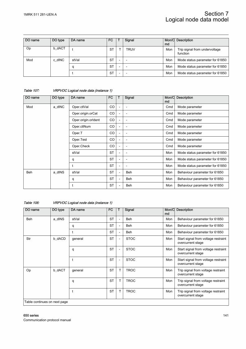
DO name DO type DA name FC T Signal Mon/Cmd
Description
Op b_dACT t ST T TRUV Mon Trip signal from undervoltagefunction
Mod c_dINC stVal ST - - Mon Mode status parameter for 61850
q ST - - Mon Mode status parameter for 61850
t ST - - Mon Mode status parameter for 61850
Table 107: VRPVOC Logical node data (instance 1)
DO name DO type DA name FC T Signal Mon/Cmd
Description
Mod a_dINC Oper.ctlVal CO - - Cmd Mode parameter
Oper.origin.orCat CO - - Cmd Mode parameter
Oper.origin.orIdent CO - - Cmd Mode parameter
Oper.ctlNum CO - - Cmd Mode parameter
Oper.T CO - - Cmd Mode parameter
Oper.Test CO - - Cmd Mode parameter
Oper.Check CO - - Cmd Mode parameter
stVal ST - - Mon Mode status parameter for 61850
q ST - - Mon Mode status parameter for 61850
t ST - - Mon Mode status parameter for 61850
Beh a_dINS stVal ST - Beh Mon Behaviour parameter for 61850
q ST - Beh Mon Behaviour parameter for 61850
t ST - Beh Mon Behaviour parameter for 61850
Table 108: VRPVOC Logical node data (instance 1)
DO name DO type DA name FC T Signal Mon/Cmd
Description
Beh a_dINS stVal ST - Beh Mon Behaviour parameter for 61850
q ST - Beh Mon Behaviour parameter for 61850
t ST - Beh Mon Behaviour parameter for 61850
Str b_dACD general ST - STOC Mon Start signal from voltage restraintovercurrent stage
q ST - STOC Mon Start signal from voltage restraintovercurrent stage
t ST - STOC Mon Start signal from voltage restraintovercurrent stage
Op b_dACT general ST T TROC Mon Trip signal from voltage restraintovercurrent stage
q ST T TROC Mon Trip signal from voltage restraintovercurrent stage
t ST T TROC Mon Trip signal from voltage restraintovercurrent stage
Table continues on next page
1MRK 511 281-UEN A Section 7Logical node data model
650 series 141Communication protocol manual
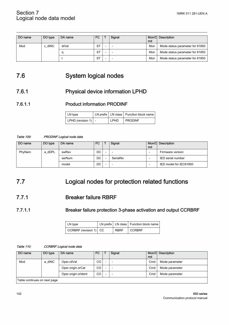
DO name DO type DA name FC T Signal Mon/Cmd
Description
Mod c_dINC stVal ST - - Mon Mode status parameter for 61850
q ST - - Mon Mode status parameter for 61850
t ST - - Mon Mode status parameter for 61850
7.6 System logical nodes
7.6.1 Physical device information LPHD
7.6.1.1 Product information PRODINF
LN type LN prefix LN class Function block name
LPHD (revision 1) - LPHD PRODINF
Table 109: PRODINF Logical node data
DO name DO type DA name FC T Signal Mon/Cmd
Description
PhyNam a_dDPL swRev DC - - - Firmware version
serNum DC - SerialNo - IED serial number
model DC - - - IED model for IEC61850
7.7 Logical nodes for protection related functions
7.7.1 Breaker failure RBRF
7.7.1.1 Breaker failure protection 3-phase activation and output CCRBRF
LN type LN prefix LN class Function block name
CCRBRF (revision 1) CC RBRF CCRBRF
Table 110: CCRBRF Logical node data
DO name DO type DA name FC T Signal Mon/Cmd
Description
Mod a_dINC Oper.ctlVal CO - - Cmd Mode parameter
Oper.origin.orCat CO - - Cmd Mode parameter
Oper.origin.orIdent CO - - Cmd Mode parameter
Table continues on next page
Section 7 1MRK 511 281-UEN ALogical node data model
142 650 seriesCommunication protocol manual

DO name DO type DA name FC T Signal Mon/Cmd
Description
Mod a_dINC Oper.ctlNum CO - - Cmd Mode parameter
Oper.T CO - - Cmd Mode parameter
Oper.Test CO - - Cmd Mode parameter
Oper.Check CO - - Cmd Mode parameter
stVal ST - - Mon Mode status parameter for 61850
q ST - - Mon Mode status parameter for 61850
t ST - - Mon Mode status parameter for 61850
Beh a_dINS stVal ST - Beh Mon Behaviour parameter for 61850
q ST - Beh Mon Behaviour parameter for 61850
t ST - Beh Mon Behaviour parameter for 61850
OpEx b_dACT general ST T TRBU Mon Back-up trip by breaker failureprotection function
q ST T TRBU Mon Back-up trip by breaker failureprotection function
t ST T TRBU Mon Back-up trip by breaker failureprotection function
OpIn b_dACT general ST T TRRET Mon Retrip by breaker failure protectionfunction
q ST T TRRET Mon Retrip by breaker failure protectionfunction
t ST T TRRET Mon Retrip by breaker failure protectionfunction
7.7.1.2 Breaker failure protection phase segregated activation and outputCSPRBRF
LN type LN prefix LN class Function block name
CSPRBRF (revision 0) CSP RBRF CSPRBRF
Table 111: CSPRBRF Logical node data
DO name DO type DA name FC T Signal Mon/Cmd
Description
OpIn a_dACT general ST T TRRET Mon Retrip
phsA ST T TRRETL1 Mon Retrip of phase L1
phsB ST T TRRETL2 Mon Retrip of phase L2
phsC ST T TRRETL3 Mon Retrip of phase L3
q ST T TRRET Mon Retrip
t ST T TRRET Mon Retrip
Mod a_dINC Oper.ctlVal CO - - Cmd Mode parameter
Oper.origin.orCat CO - - Cmd Mode parameter
Oper.origin.orIdent CO - - Cmd Mode parameter
Table continues on next page
1MRK 511 281-UEN A Section 7Logical node data model
650 series 143Communication protocol manual
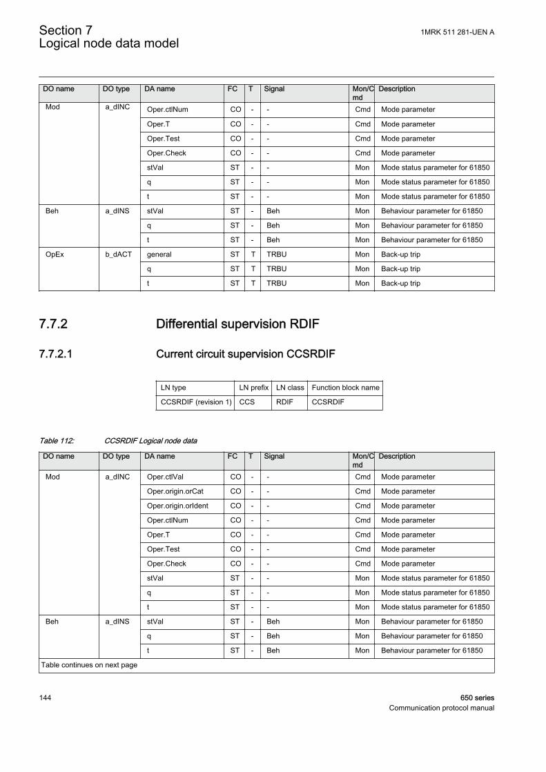
DO name DO type DA name FC T Signal Mon/Cmd
Description
Mod a_dINC Oper.ctlNum CO - - Cmd Mode parameter
Oper.T CO - - Cmd Mode parameter
Oper.Test CO - - Cmd Mode parameter
Oper.Check CO - - Cmd Mode parameter
stVal ST - - Mon Mode status parameter for 61850
q ST - - Mon Mode status parameter for 61850
t ST - - Mon Mode status parameter for 61850
Beh a_dINS stVal ST - Beh Mon Behaviour parameter for 61850
q ST - Beh Mon Behaviour parameter for 61850
t ST - Beh Mon Behaviour parameter for 61850
OpEx b_dACT general ST T TRBU Mon Back-up trip
q ST T TRBU Mon Back-up trip
t ST T TRBU Mon Back-up trip
7.7.2 Differential supervision RDIF
7.7.2.1 Current circuit supervision CCSRDIF
LN type LN prefix LN class Function block name
CCSRDIF (revision 1) CCS RDIF CCSRDIF
Table 112: CCSRDIF Logical node data
DO name DO type DA name FC T Signal Mon/Cmd
Description
Mod a_dINC Oper.ctlVal CO - - Cmd Mode parameter
Oper.origin.orCat CO - - Cmd Mode parameter
Oper.origin.orIdent CO - - Cmd Mode parameter
Oper.ctlNum CO - - Cmd Mode parameter
Oper.T CO - - Cmd Mode parameter
Oper.Test CO - - Cmd Mode parameter
Oper.Check CO - - Cmd Mode parameter
stVal ST - - Mon Mode status parameter for 61850
q ST - - Mon Mode status parameter for 61850
t ST - - Mon Mode status parameter for 61850
Beh a_dINS stVal ST - Beh Mon Behaviour parameter for 61850
q ST - Beh Mon Behaviour parameter for 61850
t ST - Beh Mon Behaviour parameter for 61850
Table continues on next page
Section 7 1MRK 511 281-UEN ALogical node data model
144 650 seriesCommunication protocol manual
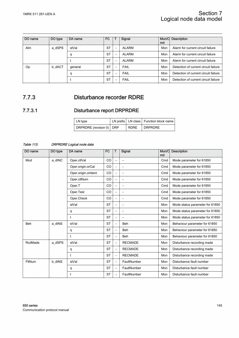
DO name DO type DA name FC T Signal Mon/Cmd
Description
Alm a_dSPS stVal ST - ALARM Mon Alarm for current circuit failure
q ST - ALARM Mon Alarm for current circuit failure
t ST - ALARM Mon Alarm for current circuit failure
Op b_dACT general ST - FAIL Mon Detection of current circuit failure
q ST - FAIL Mon Detection of current circuit failure
t ST - FAIL Mon Detection of current circuit failure
7.7.3 Disturbance recorder RDRE
7.7.3.1 Disturbance report DRPRDRE
LN type LN prefix LN class Function block name
DRPRDRE (revision 0) DRP RDRE DRPRDRE
Table 113: DRPRDRE Logical node data
DO name DO type DA name FC T Signal Mon/Cmd
Description
Mod a_dINC Oper.ctlVal CO - - Cmd Mode parameter for 61850
Oper.origin.orCat CO - - Cmd Mode parameter for 61850
Oper.origin.orIdent CO - - Cmd Mode parameter for 61850
Oper.ctlNum CO - - Cmd Mode parameter for 61850
Oper.T CO - - Cmd Mode parameter for 61850
Oper.Test CO - - Cmd Mode parameter for 61850
Oper.Check CO - - Cmd Mode parameter for 61850
stVal ST - - Mon Mode status parameter for 61850
q ST - - Mon Mode status parameter for 61850
t ST - - Mon Mode status parameter for 61850
Beh a_dINS stVal ST - Beh Mon Behaviour parameter for 61850
q ST - Beh Mon Behaviour parameter for 61850
t ST - Beh Mon Behaviour parameter for 61850
RcdMade a_dSPS stVal ST - RECMADE Mon Disturbance recording made
q ST - RECMADE Mon Disturbance recording made
t ST - RECMADE Mon Disturbance recording made
FltNum b_dINS stVal ST - FaultNumber Mon Disturbance fault number
q ST - FaultNumber Mon Disturbance fault number
t ST - FaultNumber Mon Disturbance fault number
1MRK 511 281-UEN A Section 7Logical node data model
650 series 145Communication protocol manual
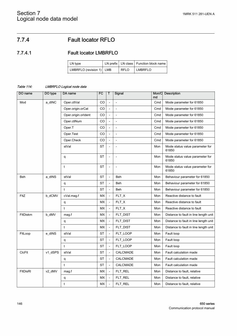
7.7.4 Fault locator RFLO
7.7.4.1 Fault locator LMBRFLO
LN type LN prefix LN class Function block name
LMBRFLO (revision 1) LMB RFLO LMBRFLO
Table 114: LMBRFLO Logical node data
DO name DO type DA name FC T Signal Mon/Cmd
Description
Mod a_dINC Oper.ctlVal CO - - Cmd Mode parameter for 61850
Oper.origin.orCat CO - - Cmd Mode parameter for 61850
Oper.origin.orIdent CO - - Cmd Mode parameter for 61850
Oper.ctlNum CO - - Cmd Mode parameter for 61850
Oper.T CO - - Cmd Mode parameter for 61850
Oper.Test CO - - Cmd Mode parameter for 61850
Oper.Check CO - - Cmd Mode parameter for 61850
stVal ST - - Mon Mode status value parameter for61850
q ST - - Mon Mode status value parameter for61850
t ST - - Mon Mode status value parameter for61850
Beh a_dINS stVal ST - Beh Mon Behaviour parameter for 61850
q ST - Beh Mon Behaviour parameter for 61850
t ST - Beh Mon Behaviour parameter for 61850
FltZ b_dCMV cVal.mag.f MX - FLT_X Mon Reactive distance to fault
q MX - FLT_X Mon Reactive distance to fault
t MX - FLT_X Mon Reactive distance to fault
FltDiskm b_dMV mag.f MX - FLT_DIST Mon Distance to fault in line length unit
q MX - FLT_DIST Mon Distance to fault in line length unit
t MX - FLT_DIST Mon Distance to fault in line length unit
FltLoop e_dINS stVal ST - FLT_LOOP Mon Fault loop
q ST - FLT_LOOP Mon Fault loop
t ST - FLT_LOOP Mon Fault loop
ClcFlt v1_dSPS stVal ST - CALCMADE Mon Fault calculation made
q ST - CALCMADE Mon Fault calculation made
t ST - CALCMADE Mon Fault calculation made
FltDisRl v2_dMV mag.f MX - FLT_REL Mon Distance to fault, relative
q MX - FLT_REL Mon Distance to fault, relative
t MX - FLT_REL Mon Distance to fault, relative
Section 7 1MRK 511 281-UEN ALogical node data model
146 650 seriesCommunication protocol manual
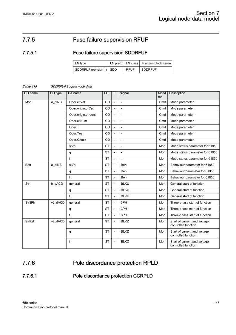
7.7.5 Fuse failure supervision RFUF
7.7.5.1 Fuse failure supervision SDDRFUF
LN type LN prefix LN class Function block name
SDDRFUF (revision 1) SDD RFUF SDDRFUF
Table 115: SDDRFUF Logical node data
DO name DO type DA name FC T Signal Mon/Cmd
Description
Mod a_dINC Oper.ctlVal CO - - Cmd Mode parameter
Oper.origin.orCat CO - - Cmd Mode parameter
Oper.origin.orIdent CO - - Cmd Mode parameter
Oper.ctlNum CO - - Cmd Mode parameter
Oper.T CO - - Cmd Mode parameter
Oper.Test CO - - Cmd Mode parameter
Oper.Check CO - - Cmd Mode parameter
stVal ST - - Mon Mode status parameter for 61850
q ST - - Mon Mode status parameter for 61850
t ST - - Mon Mode status parameter for 61850
Beh a_dINS stVal ST - Beh Mon Behaviour parameter for 61850
q ST - Beh Mon Behaviour parameter for 61850
t ST - Beh Mon Behaviour parameter for 61850
Str b_dACD general ST - BLKU Mon General start of function
q ST - BLKU Mon General start of function
t ST - BLKU Mon General start of function
Str3Ph v2_dACD general ST - 3PH Mon Three-phase start of function
q ST - 3PH Mon Three-phase start of function
t ST - 3PH Mon Three-phase start of function
StrRst v2_dACD general ST - BLKZ Mon Start of current and voltagecontrolled function
q ST - BLKZ Mon Start of current and voltagecontrolled function
t ST - BLKZ Mon Start of current and voltagecontrolled function
7.7.6 Pole discordance protection RPLD
7.7.6.1 Pole discordance protection CCRPLD
1MRK 511 281-UEN A Section 7Logical node data model
650 series 147Communication protocol manual

LN type LN prefix LN class Function block name
CCRPLD (revision 1) CC RPLD CCRPLD
Table 116: CCRPLD Logical node data
DO name DO type DA name FC T Signal Mon/Cmd
Description
Mod a_dINC Oper.ctlVal CO - - Cmd Mode parameter
Oper.origin.orCat CO - - Cmd Mode parameter
Oper.origin.orIdent CO - - Cmd Mode parameter
Oper.ctlNum CO - - Cmd Mode parameter
Oper.T CO - - Cmd Mode parameter
Oper.Test CO - - Cmd Mode parameter
Oper.Check CO - - Cmd Mode parameter
stVal ST - - Mon Mode status parameter for 61850
q ST - - Mon Mode status parameter for 61850
t ST - - Mon Mode status parameter for 61850
Beh a_dINS stVal ST - Beh Mon Behaviour parameter for 61850
q ST - Beh Mon Behaviour parameter for 61850
t ST - Beh Mon Behaviour parameter for 61850
Str b_dACD general ST - START Mon Trip condition TRUE, waiting fortime delay
q ST - START Mon Trip condition TRUE, waiting fortime delay
t ST - START Mon Trip condition TRUE, waiting fortime delay
Op b_dACT general ST T TRIP Mon Trip signal to CB
q ST T TRIP Mon Trip signal to CB
t ST T TRIP Mon Trip signal to CB
7.7.7 Power swing detection RPSB
7.7.7.1 Power swing detection ZMRPSB
LN type LN prefix LN class Function block name
ZMRPSB (revision 2) ZM RPSB ZMRPSB
Section 7 1MRK 511 281-UEN ALogical node data model
148 650 seriesCommunication protocol manual

Table 117: ZMRPSB Logical node data
DO name DO type DA name FC T Signal Mon/Cmd
Description
Mod a_dINC Oper.ctlVal CO - - Cmd Mode parameter
Oper.origin.orCat CO - - Cmd Mode parameter
Oper.origin.orIdent CO - - Cmd Mode parameter
Oper.ctlNum CO - - Cmd Mode parameter
Oper.T CO - - Cmd Mode parameter
Oper.Test CO - - Cmd Mode parameter
Oper.Check CO - - Cmd Mode parameter
stVal ST - - Mon Mode status parameter for 61850
q ST - - Mon Mode status parameter for 61850
t ST - - Mon Mode status parameter for 61850
Beh a_dINS stVal ST - Beh Mon Behaviour parameter for 61850
q ST - Beh Mon Behaviour parameter for 61850
t ST - Beh Mon Behaviour parameter for 61850
BlkZn a_dSPS stVal ST - START Mon Power swing detected
q ST - START Mon Power swing detected
t ST - START Mon Power swing detected
Str b_dACD general ST - START Mon Power swing detected
q ST - START Mon Power swing detected
t ST - START Mon Power swing detected
ZOuter v1_dSPS stVal ST - ZOUT Mon Measured impedance within outerimpedance boundary
q ST - ZOUT Mon Measured impedance within outerimpedance boundary
t ST - ZOUT Mon Measured impedance within outerimpedance boundary
ZInner v1_dSPS stVal ST - ZIN Mon Measured impedance within innerimpedance boundary
q ST - ZIN Mon Measured impedance within innerimpedance boundary
t ST - ZIN Mon Measured impedance within innerimpedance boundary
7.7.8 Autoreclosing RREC
7.7.8.1 Autorecloser for 3-phase operation SMBRREC
LN type LN prefix LN class Function block name
SMBRREC (revision 2) SMB RREC SMBRREC
1MRK 511 281-UEN A Section 7Logical node data model
650 series 149Communication protocol manual
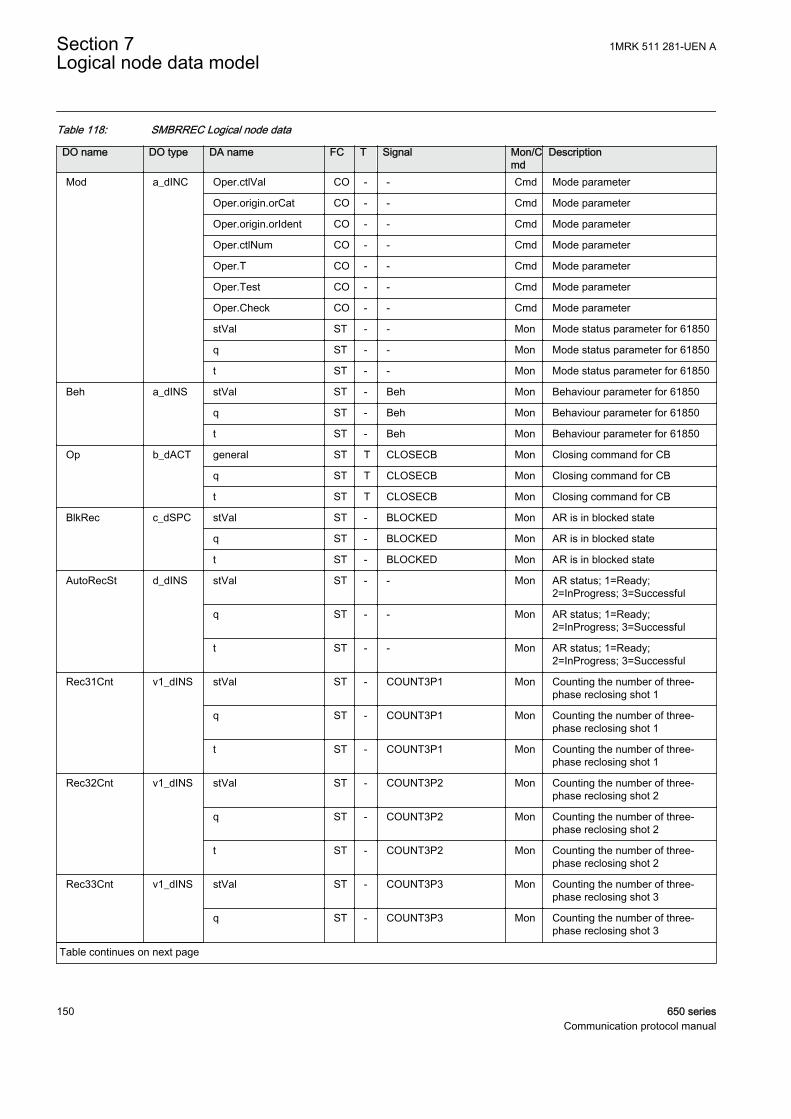
Table 118: SMBRREC Logical node data
DO name DO type DA name FC T Signal Mon/Cmd
Description
Mod a_dINC Oper.ctlVal CO - - Cmd Mode parameter
Oper.origin.orCat CO - - Cmd Mode parameter
Oper.origin.orIdent CO - - Cmd Mode parameter
Oper.ctlNum CO - - Cmd Mode parameter
Oper.T CO - - Cmd Mode parameter
Oper.Test CO - - Cmd Mode parameter
Oper.Check CO - - Cmd Mode parameter
stVal ST - - Mon Mode status parameter for 61850
q ST - - Mon Mode status parameter for 61850
t ST - - Mon Mode status parameter for 61850
Beh a_dINS stVal ST - Beh Mon Behaviour parameter for 61850
q ST - Beh Mon Behaviour parameter for 61850
t ST - Beh Mon Behaviour parameter for 61850
Op b_dACT general ST T CLOSECB Mon Closing command for CB
q ST T CLOSECB Mon Closing command for CB
t ST T CLOSECB Mon Closing command for CB
BlkRec c_dSPC stVal ST - BLOCKED Mon AR is in blocked state
q ST - BLOCKED Mon AR is in blocked state
t ST - BLOCKED Mon AR is in blocked state
AutoRecSt d_dINS stVal ST - - Mon AR status; 1=Ready;2=InProgress; 3=Successful
q ST - - Mon AR status; 1=Ready;2=InProgress; 3=Successful
t ST - - Mon AR status; 1=Ready;2=InProgress; 3=Successful
Rec31Cnt v1_dINS stVal ST - COUNT3P1 Mon Counting the number of three-phase reclosing shot 1
q ST - COUNT3P1 Mon Counting the number of three-phase reclosing shot 1
t ST - COUNT3P1 Mon Counting the number of three-phase reclosing shot 1
Rec32Cnt v1_dINS stVal ST - COUNT3P2 Mon Counting the number of three-phase reclosing shot 2
q ST - COUNT3P2 Mon Counting the number of three-phase reclosing shot 2
t ST - COUNT3P2 Mon Counting the number of three-phase reclosing shot 2
Rec33Cnt v1_dINS stVal ST - COUNT3P3 Mon Counting the number of three-phase reclosing shot 3
q ST - COUNT3P3 Mon Counting the number of three-phase reclosing shot 3
Table continues on next page
Section 7 1MRK 511 281-UEN ALogical node data model
150 650 seriesCommunication protocol manual
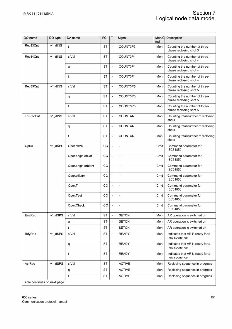
DO name DO type DA name FC T Signal Mon/Cmd
Description
Rec33Cnt v1_dINS t ST - COUNT3P3 Mon Counting the number of three-phase reclosing shot 3
Rec34Cnt v1_dINS stVal ST - COUNT3P4 Mon Counting the number of three-phase reclosing shot 4
q ST - COUNT3P4 Mon Counting the number of three-phase reclosing shot 4
t ST - COUNT3P4 Mon Counting the number of three-phase reclosing shot 4
Rec35Cnt v1_dINS stVal ST - COUNT3P5 Mon Counting the number of three-phase reclosing shot 5
q ST - COUNT3P5 Mon Counting the number of three-phase reclosing shot 5
t ST - COUNT3P5 Mon Counting the number of three-phase reclosing shot 5
TotRecCnt v1_dINS stVal ST - COUNTAR Mon Counting total number of reclosingshots
q ST - COUNTAR Mon Counting total number of reclosingshots
t ST - COUNTAR Mon Counting total number of reclosingshots
OpRs v1_dSPC Oper.ctlVal CO - - Cmd Command parameter forIEC61850
Oper.origin.orCat CO - - Cmd Command parameter forIEC61850
Oper.origin.orIdent CO - - Cmd Command parameter forIEC61850
Oper.ctlNum CO - - Cmd Command parameter forIEC61850
Oper.T CO - - Cmd Command parameter forIEC61850
Oper.Test CO - - Cmd Command parameter forIEC61850
Oper.Check CO - - Cmd Command parameter forIEC61850
EnaRec v1_dSPS stVal ST - SETON Mon AR operation is switched on
q ST - SETON Mon AR operation is switched on
t ST - SETON Mon AR operation is switched on
RdyRec v1_dSPS stVal ST - READY Mon Indicates that AR is ready for anew sequence
q ST - READY Mon Indicates that AR is ready for anew sequence
t ST - READY Mon Indicates that AR is ready for anew sequence
ActRec v1_dSPS stVal ST - ACTIVE Mon Reclosing sequence in progress
q ST - ACTIVE Mon Reclosing sequence in progress
t ST - ACTIVE Mon Reclosing sequence in progress
Table continues on next page
1MRK 511 281-UEN A Section 7Logical node data model
650 series 151Communication protocol manual
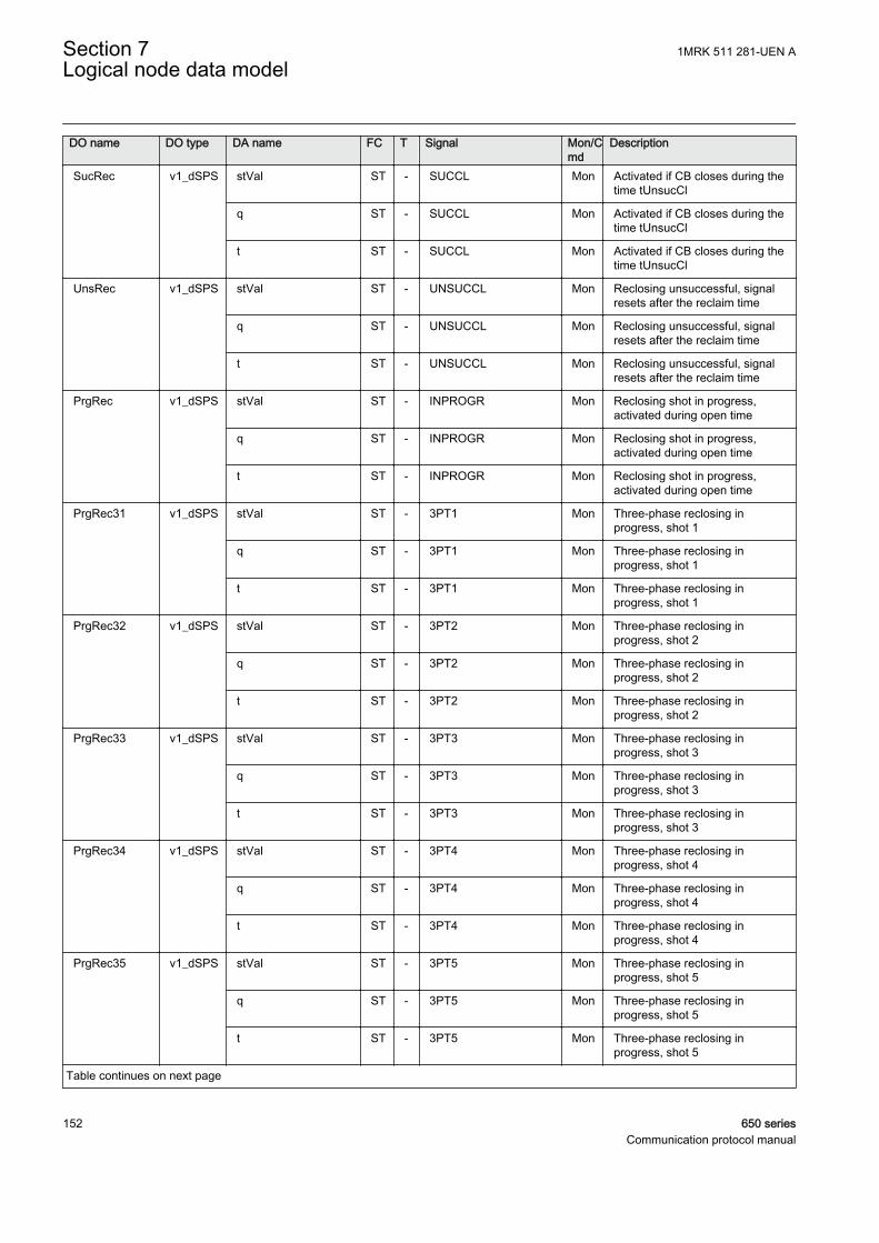
DO name DO type DA name FC T Signal Mon/Cmd
Description
SucRec v1_dSPS stVal ST - SUCCL Mon Activated if CB closes during thetime tUnsucCl
q ST - SUCCL Mon Activated if CB closes during thetime tUnsucCl
t ST - SUCCL Mon Activated if CB closes during thetime tUnsucCl
UnsRec v1_dSPS stVal ST - UNSUCCL Mon Reclosing unsuccessful, signalresets after the reclaim time
q ST - UNSUCCL Mon Reclosing unsuccessful, signalresets after the reclaim time
t ST - UNSUCCL Mon Reclosing unsuccessful, signalresets after the reclaim time
PrgRec v1_dSPS stVal ST - INPROGR Mon Reclosing shot in progress,activated during open time
q ST - INPROGR Mon Reclosing shot in progress,activated during open time
t ST - INPROGR Mon Reclosing shot in progress,activated during open time
PrgRec31 v1_dSPS stVal ST - 3PT1 Mon Three-phase reclosing inprogress, shot 1
q ST - 3PT1 Mon Three-phase reclosing inprogress, shot 1
t ST - 3PT1 Mon Three-phase reclosing inprogress, shot 1
PrgRec32 v1_dSPS stVal ST - 3PT2 Mon Three-phase reclosing inprogress, shot 2
q ST - 3PT2 Mon Three-phase reclosing inprogress, shot 2
t ST - 3PT2 Mon Three-phase reclosing inprogress, shot 2
PrgRec33 v1_dSPS stVal ST - 3PT3 Mon Three-phase reclosing inprogress, shot 3
q ST - 3PT3 Mon Three-phase reclosing inprogress, shot 3
t ST - 3PT3 Mon Three-phase reclosing inprogress, shot 3
PrgRec34 v1_dSPS stVal ST - 3PT4 Mon Three-phase reclosing inprogress, shot 4
q ST - 3PT4 Mon Three-phase reclosing inprogress, shot 4
t ST - 3PT4 Mon Three-phase reclosing inprogress, shot 4
PrgRec35 v1_dSPS stVal ST - 3PT5 Mon Three-phase reclosing inprogress, shot 5
q ST - 3PT5 Mon Three-phase reclosing inprogress, shot 5
t ST - 3PT5 Mon Three-phase reclosing inprogress, shot 5
Table continues on next page
Section 7 1MRK 511 281-UEN ALogical node data model
152 650 seriesCommunication protocol manual
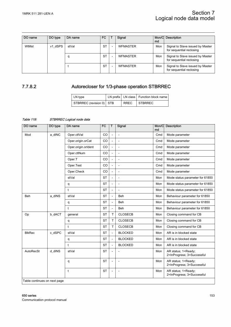
DO name DO type DA name FC T Signal Mon/Cmd
Description
WtMst v1_dSPS stVal ST - WFMASTER Mon Signal to Slave issued by Masterfor sequential reclosing
q ST - WFMASTER Mon Signal to Slave issued by Masterfor sequential reclosing
t ST - WFMASTER Mon Signal to Slave issued by Masterfor sequential reclosing
7.7.8.2 Autorecloser for 1/3-phase operation STBRREC
LN type LN prefix LN class Function block name
STBRREC (revision 0) STB RREC STBRREC
Table 119: STBRREC Logical node data
DO name DO type DA name FC T Signal Mon/Cmd
Description
Mod a_dINC Oper.ctlVal CO - - Cmd Mode parameter
Oper.origin.orCat CO - - Cmd Mode parameter
Oper.origin.orIdent CO - - Cmd Mode parameter
Oper.ctlNum CO - - Cmd Mode parameter
Oper.T CO - - Cmd Mode parameter
Oper.Test CO - - Cmd Mode parameter
Oper.Check CO - - Cmd Mode parameter
stVal ST - - Mon Mode status parameter for 61850
q ST - - Mon Mode status parameter for 61850
t ST - - Mon Mode status parameter for 61850
Beh a_dINS stVal ST - Beh Mon Behaviour parameter for 61850
q ST - Beh Mon Behaviour parameter for 61850
t ST - Beh Mon Behaviour parameter for 61850
Op b_dACT general ST T CLOSECB Mon Closing command for CB
q ST T CLOSECB Mon Closing command for CB
t ST T CLOSECB Mon Closing command for CB
BlkRec c_dSPC stVal ST - BLOCKED Mon AR is in blocked state
q ST - BLOCKED Mon AR is in blocked state
t ST - BLOCKED Mon AR is in blocked state
AutoRecSt d_dINS stVal ST - - Mon AR status; 1=Ready;2=InProgress; 3=Successful
q ST - - Mon AR status; 1=Ready;2=InProgress; 3=Successful
t ST - - Mon AR status; 1=Ready;2=InProgress; 3=Successful
Table continues on next page
1MRK 511 281-UEN A Section 7Logical node data model
650 series 153Communication protocol manual

DO name DO type DA name FC T Signal Mon/Cmd
Description
Rec31Cnt v1_dINS stVal ST - COUNT3P1 Mon Counting the number of three-phase reclosing shot 1
q ST - COUNT3P1 Mon Counting the number of three-phase reclosing shot 1
t ST - COUNT3P1 Mon Counting the number of three-phase reclosing shot 1
Rec32Cnt v1_dINS stVal ST - COUNT3P2 Mon Counting the number of three-phase reclosing shot 2
q ST - COUNT3P2 Mon Counting the number of three-phase reclosing shot 2
t ST - COUNT3P2 Mon Counting the number of three-phase reclosing shot 2
Rec33Cnt v1_dINS stVal ST - COUNT3P3 Mon Counting the number of three-phase reclosing shot 3
q ST - COUNT3P3 Mon Counting the number of three-phase reclosing shot 3
t ST - COUNT3P3 Mon Counting the number of three-phase reclosing shot 3
Rec34Cnt v1_dINS stVal ST - COUNT3P4 Mon Counting the number of three-phase reclosing shot 4
q ST - COUNT3P4 Mon Counting the number of three-phase reclosing shot 4
t ST - COUNT3P4 Mon Counting the number of three-phase reclosing shot 4
Rec35Cnt v1_dINS stVal ST - COUNT3P5 Mon Counting the number of three-phase reclosing shot 5
q ST - COUNT3P5 Mon Counting the number of three-phase reclosing shot 5
t ST - COUNT3P5 Mon Counting the number of three-phase reclosing shot 5
TotRecCnt v1_dINS stVal ST - COUNTAR Mon Counting total number of reclosingshots
q ST - COUNTAR Mon Counting total number of reclosingshots
t ST - COUNTAR Mon Counting total number of reclosingshots
Rec1PhCnt v1_dINS stVal ST - COUNT1P Mon Counting the number of single-phase reclosing shots
q ST - COUNT1P Mon Counting the number of single-phase reclosing shots
t ST - COUNT1P Mon Counting the number of single-phase reclosing shots
OpRs v1_dSPC Oper.ctlVal CO - - Cmd Command parameter forIEC61850
Oper.origin.orCat CO - - Cmd Command parameter forIEC61850
Oper.origin.orIdent CO - - Cmd Command parameter forIEC61850
Table continues on next page
Section 7 1MRK 511 281-UEN ALogical node data model
154 650 seriesCommunication protocol manual
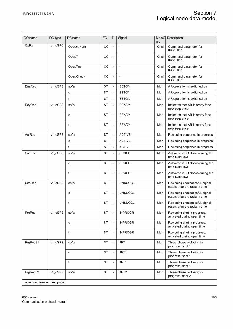
DO name DO type DA name FC T Signal Mon/Cmd
Description
OpRs v1_dSPC Oper.ctlNum CO - - Cmd Command parameter forIEC61850
Oper.T CO - - Cmd Command parameter forIEC61850
Oper.Test CO - - Cmd Command parameter forIEC61850
Oper.Check CO - - Cmd Command parameter forIEC61850
EnaRec v1_dSPS stVal ST - SETON Mon AR operation is switched on
q ST - SETON Mon AR operation is switched on
t ST - SETON Mon AR operation is switched on
RdyRec v1_dSPS stVal ST - READY Mon Indicates that AR is ready for anew sequence
q ST - READY Mon Indicates that AR is ready for anew sequence
t ST - READY Mon Indicates that AR is ready for anew sequence
ActRec v1_dSPS stVal ST - ACTIVE Mon Reclosing sequence in progress
q ST - ACTIVE Mon Reclosing sequence in progress
t ST - ACTIVE Mon Reclosing sequence in progress
SucRec v1_dSPS stVal ST - SUCCL Mon Activated if CB closes during thetime tUnsucCl
q ST - SUCCL Mon Activated if CB closes during thetime tUnsucCl
t ST - SUCCL Mon Activated if CB closes during thetime tUnsucCl
UnsRec v1_dSPS stVal ST - UNSUCCL Mon Reclosing unsuccessful, signalresets after the reclaim time
q ST - UNSUCCL Mon Reclosing unsuccessful, signalresets after the reclaim time
t ST - UNSUCCL Mon Reclosing unsuccessful, signalresets after the reclaim time
PrgRec v1_dSPS stVal ST - INPROGR Mon Reclosing shot in progress,activated during open time
q ST - INPROGR Mon Reclosing shot in progress,activated during open time
t ST - INPROGR Mon Reclosing shot in progress,activated during open time
PrgRec31 v1_dSPS stVal ST - 3PT1 Mon Three-phase reclosing inprogress, shot 1
q ST - 3PT1 Mon Three-phase reclosing inprogress, shot 1
t ST - 3PT1 Mon Three-phase reclosing inprogress, shot 1
PrgRec32 v1_dSPS stVal ST - 3PT2 Mon Three-phase reclosing inprogress, shot 2
Table continues on next page
1MRK 511 281-UEN A Section 7Logical node data model
650 series 155Communication protocol manual
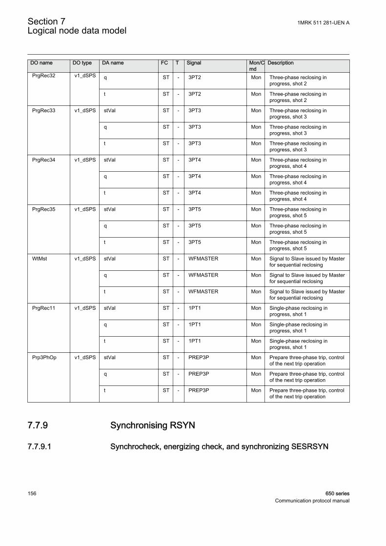
DO name DO type DA name FC T Signal Mon/Cmd
Description
PrgRec32 v1_dSPS q ST - 3PT2 Mon Three-phase reclosing inprogress, shot 2
t ST - 3PT2 Mon Three-phase reclosing inprogress, shot 2
PrgRec33 v1_dSPS stVal ST - 3PT3 Mon Three-phase reclosing inprogress, shot 3
q ST - 3PT3 Mon Three-phase reclosing inprogress, shot 3
t ST - 3PT3 Mon Three-phase reclosing inprogress, shot 3
PrgRec34 v1_dSPS stVal ST - 3PT4 Mon Three-phase reclosing inprogress, shot 4
q ST - 3PT4 Mon Three-phase reclosing inprogress, shot 4
t ST - 3PT4 Mon Three-phase reclosing inprogress, shot 4
PrgRec35 v1_dSPS stVal ST - 3PT5 Mon Three-phase reclosing inprogress, shot 5
q ST - 3PT5 Mon Three-phase reclosing inprogress, shot 5
t ST - 3PT5 Mon Three-phase reclosing inprogress, shot 5
WtMst v1_dSPS stVal ST - WFMASTER Mon Signal to Slave issued by Masterfor sequential reclosing
q ST - WFMASTER Mon Signal to Slave issued by Masterfor sequential reclosing
t ST - WFMASTER Mon Signal to Slave issued by Masterfor sequential reclosing
PrgRec11 v1_dSPS stVal ST - 1PT1 Mon Single-phase reclosing inprogress, shot 1
q ST - 1PT1 Mon Single-phase reclosing inprogress, shot 1
t ST - 1PT1 Mon Single-phase reclosing inprogress, shot 1
Prp3PhOp v1_dSPS stVal ST - PREP3P Mon Prepare three-phase trip, controlof the next trip operation
q ST - PREP3P Mon Prepare three-phase trip, controlof the next trip operation
t ST - PREP3P Mon Prepare three-phase trip, controlof the next trip operation
7.7.9 Synchronising RSYN
7.7.9.1 Synchrocheck, energizing check, and synchronizing SESRSYN
Section 7 1MRK 511 281-UEN ALogical node data model
156 650 seriesCommunication protocol manual
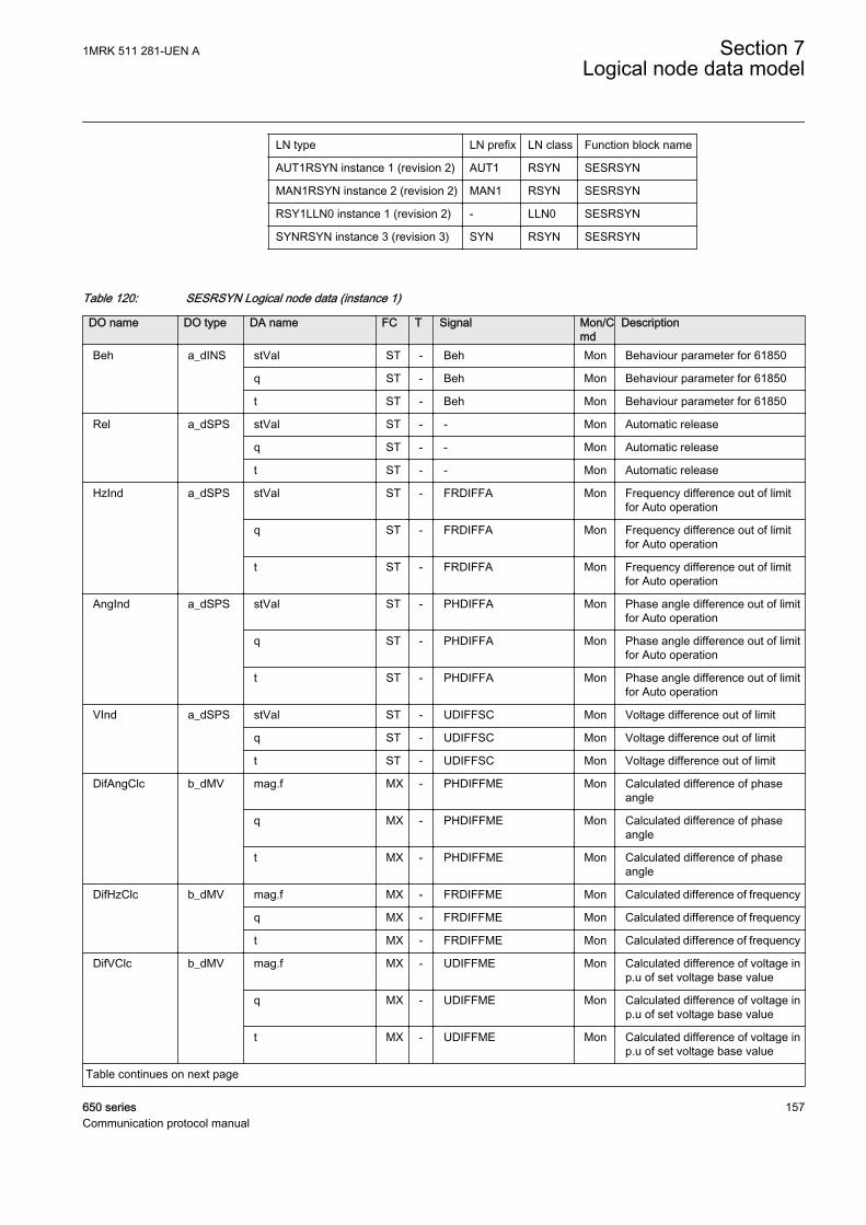
LN type LN prefix LN class Function block name
AUT1RSYN instance 1 (revision 2) AUT1 RSYN SESRSYN
MAN1RSYN instance 2 (revision 2) MAN1 RSYN SESRSYN
RSY1LLN0 instance 1 (revision 2) - LLN0 SESRSYN
SYNRSYN instance 3 (revision 3) SYN RSYN SESRSYN
Table 120: SESRSYN Logical node data (instance 1)
DO name DO type DA name FC T Signal Mon/Cmd
Description
Beh a_dINS stVal ST - Beh Mon Behaviour parameter for 61850
q ST - Beh Mon Behaviour parameter for 61850
t ST - Beh Mon Behaviour parameter for 61850
Rel a_dSPS stVal ST - - Mon Automatic release
q ST - - Mon Automatic release
t ST - - Mon Automatic release
HzInd a_dSPS stVal ST - FRDIFFA Mon Frequency difference out of limitfor Auto operation
q ST - FRDIFFA Mon Frequency difference out of limitfor Auto operation
t ST - FRDIFFA Mon Frequency difference out of limitfor Auto operation
AngInd a_dSPS stVal ST - PHDIFFA Mon Phase angle difference out of limitfor Auto operation
q ST - PHDIFFA Mon Phase angle difference out of limitfor Auto operation
t ST - PHDIFFA Mon Phase angle difference out of limitfor Auto operation
VInd a_dSPS stVal ST - UDIFFSC Mon Voltage difference out of limit
q ST - UDIFFSC Mon Voltage difference out of limit
t ST - UDIFFSC Mon Voltage difference out of limit
DifAngClc b_dMV mag.f MX - PHDIFFME Mon Calculated difference of phaseangle
q MX - PHDIFFME Mon Calculated difference of phaseangle
t MX - PHDIFFME Mon Calculated difference of phaseangle
DifHzClc b_dMV mag.f MX - FRDIFFME Mon Calculated difference of frequency
q MX - FRDIFFME Mon Calculated difference of frequency
t MX - FRDIFFME Mon Calculated difference of frequency
DifVClc b_dMV mag.f MX - UDIFFME Mon Calculated difference of voltage inp.u of set voltage base value
q MX - UDIFFME Mon Calculated difference of voltage inp.u of set voltage base value
t MX - UDIFFME Mon Calculated difference of voltage inp.u of set voltage base value
Table continues on next page
1MRK 511 281-UEN A Section 7Logical node data model
650 series 157Communication protocol manual
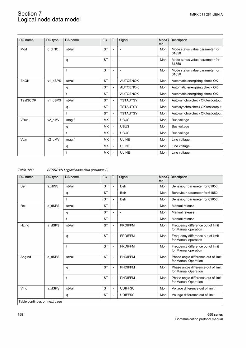
DO name DO type DA name FC T Signal Mon/Cmd
Description
Mod c_dINC stVal ST - - Mon Mode status value parameter for61850
q ST - - Mon Mode status value parameter for61850
t ST - - Mon Mode status value parameter for61850
EnOK v1_dSPS stVal ST - AUTOENOK Mon Automatic energizing check OK
q ST - AUTOENOK Mon Automatic energizing check OK
t ST - AUTOENOK Mon Automatic energizing check OK
TestSCOK v1_dSPS stVal ST - TSTAUTSY Mon Auto synchro check OK test output
q ST - TSTAUTSY Mon Auto synchro check OK test output
t ST - TSTAUTSY Mon Auto synchro check OK test output
VBus v2_dMV mag.f MX - UBUS Mon Bus voltage
q MX - UBUS Mon Bus voltage
t MX - UBUS Mon Bus voltage
VLin v2_dMV mag.f MX - ULINE Mon Line voltage
q MX - ULINE Mon Line voltage
t MX - ULINE Mon Line voltage
Table 121: SESRSYN Logical node data (instance 2)
DO name DO type DA name FC T Signal Mon/Cmd
Description
Beh a_dINS stVal ST - Beh Mon Behaviour parameter for 61850
q ST - Beh Mon Behaviour parameter for 61850
t ST - Beh Mon Behaviour parameter for 61850
Rel a_dSPS stVal ST - - Mon Manual release
q ST - - Mon Manual release
t ST - - Mon Manual release
HzInd a_dSPS stVal ST - FRDIFFM Mon Frequency difference out of limitfor Manual operation
q ST - FRDIFFM Mon Frequency difference out of limitfor Manual operation
t ST - FRDIFFM Mon Frequency difference out of limitfor Manual operation
AngInd a_dSPS stVal ST - PHDIFFM Mon Phase angle difference out of limitfor Manual Operation
q ST - PHDIFFM Mon Phase angle difference out of limitfor Manual Operation
t ST - PHDIFFM Mon Phase angle difference out of limitfor Manual Operation
VInd a_dSPS stVal ST - UDIFFSC Mon Voltage difference out of limit
q ST - UDIFFSC Mon Voltage difference out of limit
Table continues on next page
Section 7 1MRK 511 281-UEN ALogical node data model
158 650 seriesCommunication protocol manual
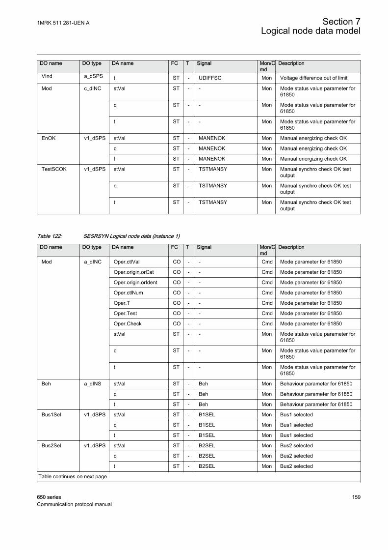
DO name DO type DA name FC T Signal Mon/Cmd
Description
VInd a_dSPS t ST - UDIFFSC Mon Voltage difference out of limit
Mod c_dINC stVal ST - - Mon Mode status value parameter for61850
q ST - - Mon Mode status value parameter for61850
t ST - - Mon Mode status value parameter for61850
EnOK v1_dSPS stVal ST - MANENOK Mon Manual energizing check OK
q ST - MANENOK Mon Manual energizing check OK
t ST - MANENOK Mon Manual energizing check OK
TestSCOK v1_dSPS stVal ST - TSTMANSY Mon Manual synchro check OK testoutput
q ST - TSTMANSY Mon Manual synchro check OK testoutput
t ST - TSTMANSY Mon Manual synchro check OK testoutput
Table 122: SESRSYN Logical node data (instance 1)
DO name DO type DA name FC T Signal Mon/Cmd
Description
Mod a_dINC Oper.ctlVal CO - - Cmd Mode parameter for 61850
Oper.origin.orCat CO - - Cmd Mode parameter for 61850
Oper.origin.orIdent CO - - Cmd Mode parameter for 61850
Oper.ctlNum CO - - Cmd Mode parameter for 61850
Oper.T CO - - Cmd Mode parameter for 61850
Oper.Test CO - - Cmd Mode parameter for 61850
Oper.Check CO - - Cmd Mode parameter for 61850
stVal ST - - Mon Mode status value parameter for61850
q ST - - Mon Mode status value parameter for61850
t ST - - Mon Mode status value parameter for61850
Beh a_dINS stVal ST - Beh Mon Behaviour parameter for 61850
q ST - Beh Mon Behaviour parameter for 61850
t ST - Beh Mon Behaviour parameter for 61850
Bus1Sel v1_dSPS stVal ST - B1SEL Mon Bus1 selected
q ST - B1SEL Mon Bus1 selected
t ST - B1SEL Mon Bus1 selected
Bus2Sel v1_dSPS stVal ST - B2SEL Mon Bus2 selected
q ST - B2SEL Mon Bus2 selected
t ST - B2SEL Mon Bus2 selected
Table continues on next page
1MRK 511 281-UEN A Section 7Logical node data model
650 series 159Communication protocol manual
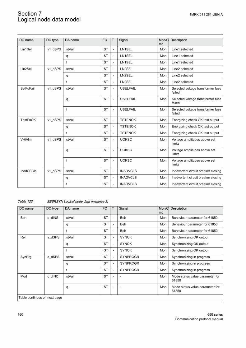
DO name DO type DA name FC T Signal Mon/Cmd
Description
Lin1Sel v1_dSPS stVal ST - LN1SEL Mon Line1 selected
q ST - LN1SEL Mon Line1 selected
t ST - LN1SEL Mon Line1 selected
Lin2Sel v1_dSPS stVal ST - LN2SEL Mon Line2 selected
q ST - LN2SEL Mon Line2 selected
t ST - LN2SEL Mon Line2 selected
SelFuFail v1_dSPS stVal ST - USELFAIL Mon Selected voltage transformer fusefailed
q ST - USELFAIL Mon Selected voltage transformer fusefailed
t ST - USELFAIL Mon Selected voltage transformer fusefailed
TestEnOK v1_dSPS stVal ST - TSTENOK Mon Energizing check OK test output
q ST - TSTENOK Mon Energizing check OK test output
t ST - TSTENOK Mon Energizing check OK test output
VHiAlm v1_dSPS stVal ST - UOKSC Mon Voltage amplitudes above setlimits
q ST - UOKSC Mon Voltage amplitudes above setlimits
t ST - UOKSC Mon Voltage amplitudes above setlimits
InadCBCls v1_dSPS stVal ST - INADVCLS Mon Inadvertent circuit breaker closing
q ST - INADVCLS Mon Inadvertent circuit breaker closing
t ST - INADVCLS Mon Inadvertent circuit breaker closing
Table 123: SESRSYN Logical node data (instance 3)
DO name DO type DA name FC T Signal Mon/Cmd
Description
Beh a_dINS stVal ST - Beh Mon Behaviour parameter for 61850
q ST - Beh Mon Behaviour parameter for 61850
t ST - Beh Mon Behaviour parameter for 61850
Rel a_dSPS stVal ST - SYNOK Mon Synchronizing OK output
q ST - SYNOK Mon Synchronizing OK output
t ST - SYNOK Mon Synchronizing OK output
SynPrg a_dSPS stVal ST - SYNPROGR Mon Synchronizing in progress
q ST - SYNPROGR Mon Synchronizing in progress
t ST - SYNPROGR Mon Synchronizing in progress
Mod c_dINC stVal ST - - Mon Mode status value parameter for61850
q ST - - Mon Mode status value parameter for61850
Table continues on next page
Section 7 1MRK 511 281-UEN ALogical node data model
160 650 seriesCommunication protocol manual
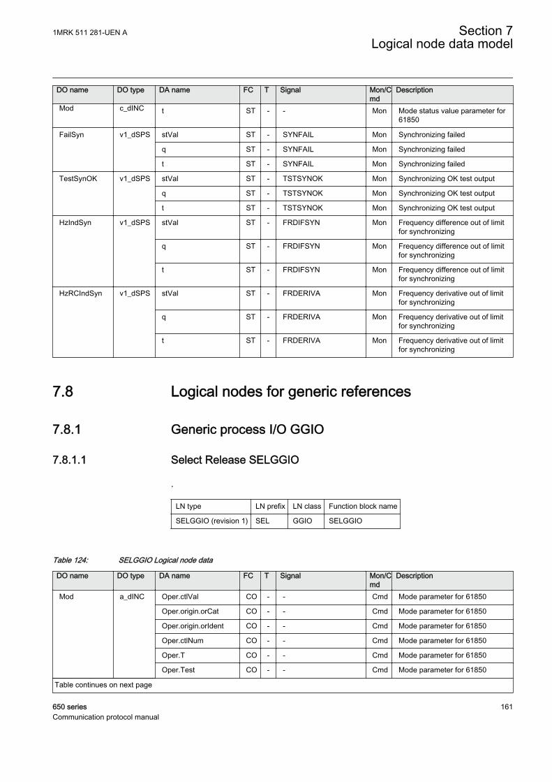
DO name DO type DA name FC T Signal Mon/Cmd
Description
Mod c_dINC t ST - - Mon Mode status value parameter for61850
FailSyn v1_dSPS stVal ST - SYNFAIL Mon Synchronizing failed
q ST - SYNFAIL Mon Synchronizing failed
t ST - SYNFAIL Mon Synchronizing failed
TestSynOK v1_dSPS stVal ST - TSTSYNOK Mon Synchronizing OK test output
q ST - TSTSYNOK Mon Synchronizing OK test output
t ST - TSTSYNOK Mon Synchronizing OK test output
HzIndSyn v1_dSPS stVal ST - FRDIFSYN Mon Frequency difference out of limitfor synchronizing
q ST - FRDIFSYN Mon Frequency difference out of limitfor synchronizing
t ST - FRDIFSYN Mon Frequency difference out of limitfor synchronizing
HzRCIndSyn v1_dSPS stVal ST - FRDERIVA Mon Frequency derivative out of limitfor synchronizing
q ST - FRDERIVA Mon Frequency derivative out of limitfor synchronizing
t ST - FRDERIVA Mon Frequency derivative out of limitfor synchronizing
7.8 Logical nodes for generic references
7.8.1 Generic process I/O GGIO
7.8.1.1 Select Release SELGGIO
.
LN type LN prefix LN class Function block name
SELGGIO (revision 1) SEL GGIO SELGGIO
Table 124: SELGGIO Logical node data
DO name DO type DA name FC T Signal Mon/Cmd
Description
Mod a_dINC Oper.ctlVal CO - - Cmd Mode parameter for 61850
Oper.origin.orCat CO - - Cmd Mode parameter for 61850
Oper.origin.orIdent CO - - Cmd Mode parameter for 61850
Oper.ctlNum CO - - Cmd Mode parameter for 61850
Oper.T CO - - Cmd Mode parameter for 61850
Oper.Test CO - - Cmd Mode parameter for 61850
Table continues on next page
1MRK 511 281-UEN A Section 7Logical node data model
650 series 161Communication protocol manual

DO name DO type DA name FC T Signal Mon/Cmd
Description
Mod a_dINC Oper.Check CO - - Cmd Mode parameter for 61850
stVal ST - - Mon Mode status parameter for 61850
q ST - - Mon Mode status parameter for 61850
t ST - - Mon Mode status parameter for 61850
Beh a_dINS stVal ST - Beh Mon Behaviour parameter for 61850
q ST - Beh Mon Behaviour parameter for 61850
t ST - Beh Mon Behaviour parameter for 61850
Rel a_dSPS stVal ST - RESERVED Mon Reserved indication from bay/apparatus
q ST - RESERVED Mon Reserved indication from bay/apparatus
t ST - RESERVED Mon Reserved indication from bay/apparatus
7.8.1.2 Logic rotating switch for function selection and LHMI presentationSLGGIO
LN type LN prefix LN class Function block name
SLGGIO (revision 2) SL GGIO SLGGIO
Table 125: SLGGIO Logical node data
DO name DO type DA name FC T Signal Mon/Cmd
Description
Mod a_dINC Oper.ctlVal CO - - Cmd Mode parameter
Oper.origin.orCat CO - - Cmd Mode parameter
Oper.origin.orIdent CO - - Cmd Mode parameter
Oper.ctlNum CO - - Cmd Mode parameter
Oper.T CO - - Cmd Mode parameter
Oper.Test CO - - Cmd Mode parameter
Oper.Check CO - - Cmd Mode parameter
stVal ST - - Mon Mode status parameter for 61850
q ST - - Mon Mode status parameter for 61850
t ST - - Mon Mode status parameter for 61850
Beh a_dINS stVal ST - Beh Mon Behaviour parameter for 61850
q ST - Beh Mon Behaviour parameter for 61850
t ST - Beh Mon Behaviour parameter for 61850
IntIn b_dINS stVal ST - SWPOSN Mon Switch position as integer value
q ST - SWPOSN Mon Switch position as integer value
t ST - SWPOSN Mon Switch position as integer value
Table continues on next page
Section 7 1MRK 511 281-UEN ALogical node data model
162 650 seriesCommunication protocol manual
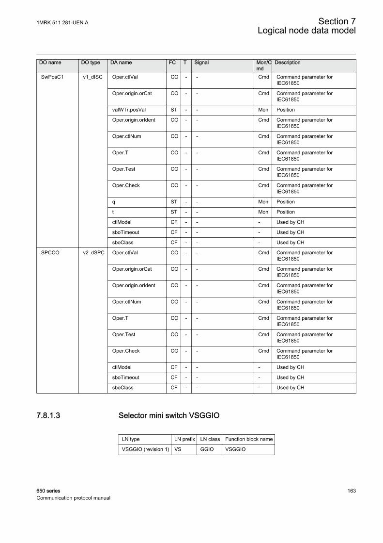
DO name DO type DA name FC T Signal Mon/Cmd
Description
SwPosC1 v1_dISC Oper.ctlVal CO - - Cmd Command parameter forIEC61850
Oper.origin.orCat CO - - Cmd Command parameter forIEC61850
valWTr.posVal ST - - Mon Position
Oper.origin.orIdent CO - - Cmd Command parameter forIEC61850
Oper.ctlNum CO - - Cmd Command parameter forIEC61850
Oper.T CO - - Cmd Command parameter forIEC61850
Oper.Test CO - - Cmd Command parameter forIEC61850
Oper.Check CO - - Cmd Command parameter forIEC61850
q ST - - Mon Position
t ST - - Mon Position
ctlModel CF - - - Used by CH
sboTimeout CF - - - Used by CH
sboClass CF - - - Used by CH
SPCCO v2_dSPC Oper.ctlVal CO - - Cmd Command parameter forIEC61850
Oper.origin.orCat CO - - Cmd Command parameter forIEC61850
Oper.origin.orIdent CO - - Cmd Command parameter forIEC61850
Oper.ctlNum CO - - Cmd Command parameter forIEC61850
Oper.T CO - - Cmd Command parameter forIEC61850
Oper.Test CO - - Cmd Command parameter forIEC61850
Oper.Check CO - - Cmd Command parameter forIEC61850
ctlModel CF - - - Used by CH
sboTimeout CF - - - Used by CH
sboClass CF - - - Used by CH
7.8.1.3 Selector mini switch VSGGIO
LN type LN prefix LN class Function block name
VSGGIO (revision 1) VS GGIO VSGGIO
1MRK 511 281-UEN A Section 7Logical node data model
650 series 163Communication protocol manual
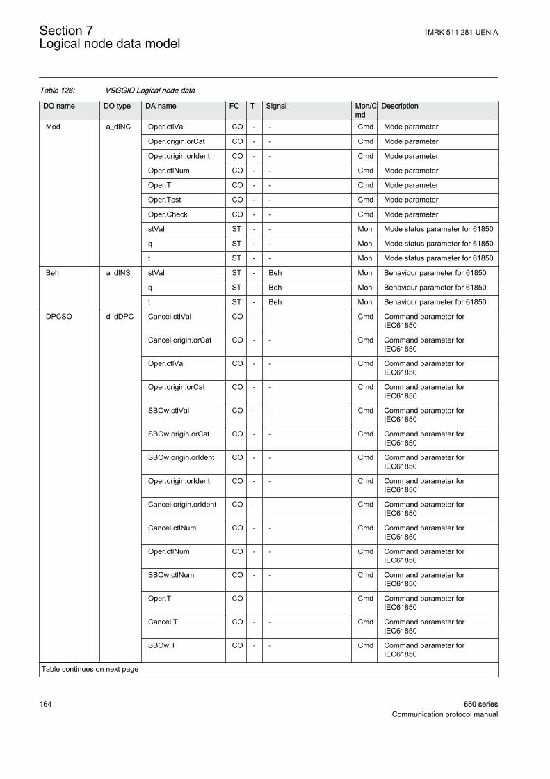
Table 126: VSGGIO Logical node data
DO name DO type DA name FC T Signal Mon/Cmd
Description
Mod a_dINC Oper.ctlVal CO - - Cmd Mode parameter
Oper.origin.orCat CO - - Cmd Mode parameter
Oper.origin.orIdent CO - - Cmd Mode parameter
Oper.ctlNum CO - - Cmd Mode parameter
Oper.T CO - - Cmd Mode parameter
Oper.Test CO - - Cmd Mode parameter
Oper.Check CO - - Cmd Mode parameter
stVal ST - - Mon Mode status parameter for 61850
q ST - - Mon Mode status parameter for 61850
t ST - - Mon Mode status parameter for 61850
Beh a_dINS stVal ST - Beh Mon Behaviour parameter for 61850
q ST - Beh Mon Behaviour parameter for 61850
t ST - Beh Mon Behaviour parameter for 61850
DPCSO d_dDPC Cancel.ctlVal CO - - Cmd Command parameter forIEC61850
Cancel.origin.orCat CO - - Cmd Command parameter forIEC61850
Oper.ctlVal CO - - Cmd Command parameter forIEC61850
Oper.origin.orCat CO - - Cmd Command parameter forIEC61850
SBOw.ctlVal CO - - Cmd Command parameter forIEC61850
SBOw.origin.orCat CO - - Cmd Command parameter forIEC61850
SBOw.origin.orIdent CO - - Cmd Command parameter forIEC61850
Oper.origin.orIdent CO - - Cmd Command parameter forIEC61850
Cancel.origin.orIdent CO - - Cmd Command parameter forIEC61850
Cancel.ctlNum CO - - Cmd Command parameter forIEC61850
Oper.ctlNum CO - - Cmd Command parameter forIEC61850
SBOw.ctlNum CO - - Cmd Command parameter forIEC61850
Oper.T CO - - Cmd Command parameter forIEC61850
Cancel.T CO - - Cmd Command parameter forIEC61850
SBOw.T CO - - Cmd Command parameter forIEC61850
Table continues on next page
Section 7 1MRK 511 281-UEN ALogical node data model
164 650 seriesCommunication protocol manual
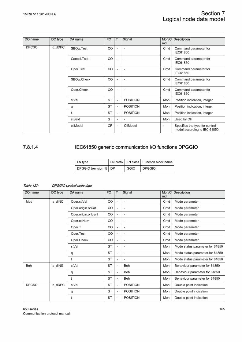
DO name DO type DA name FC T Signal Mon/Cmd
Description
DPCSO d_dDPC SBOw.Test CO - - Cmd Command parameter forIEC61850
Cancel.Test CO - - Cmd Command parameter forIEC61850
Oper.Test CO - - Cmd Command parameter forIEC61850
SBOw.Check CO - - Cmd Command parameter forIEC61850
Oper.Check CO - - Cmd Command parameter forIEC61850
stVal ST - POSITION Mon Position indication, integer
q ST - POSITION Mon Position indication, integer
t ST - POSITION Mon Position indication, integer
stSeld ST - - Mon Used by CH
ctlModel CF - CtlModel - Specifies the type for controlmodel according to IEC 61850
7.8.1.4 IEC61850 generic communication I/O functions DPGGIO
LN type LN prefix LN class Function block name
DPGGIO (revision 1) DP GGIO DPGGIO
Table 127: DPGGIO Logical node data
DO name DO type DA name FC T Signal Mon/Cmd
Description
Mod a_dINC Oper.ctlVal CO - - Cmd Mode parameter
Oper.origin.orCat CO - - Cmd Mode parameter
Oper.origin.orIdent CO - - Cmd Mode parameter
Oper.ctlNum CO - - Cmd Mode parameter
Oper.T CO - - Cmd Mode parameter
Oper.Test CO - - Cmd Mode parameter
Oper.Check CO - - Cmd Mode parameter
stVal ST - - Mon Mode status parameter for 61850
q ST - - Mon Mode status parameter for 61850
t ST - - Mon Mode status parameter for 61850
Beh a_dINS stVal ST - Beh Mon Behaviour parameter for 61850
q ST - Beh Mon Behaviour parameter for 61850
t ST - Beh Mon Behaviour parameter for 61850
DPCSO b_dDPC stVal ST - POSITION Mon Double point indication
q ST - POSITION Mon Double point indication
t ST - POSITION Mon Double point indication
1MRK 511 281-UEN A Section 7Logical node data model
650 series 165Communication protocol manual
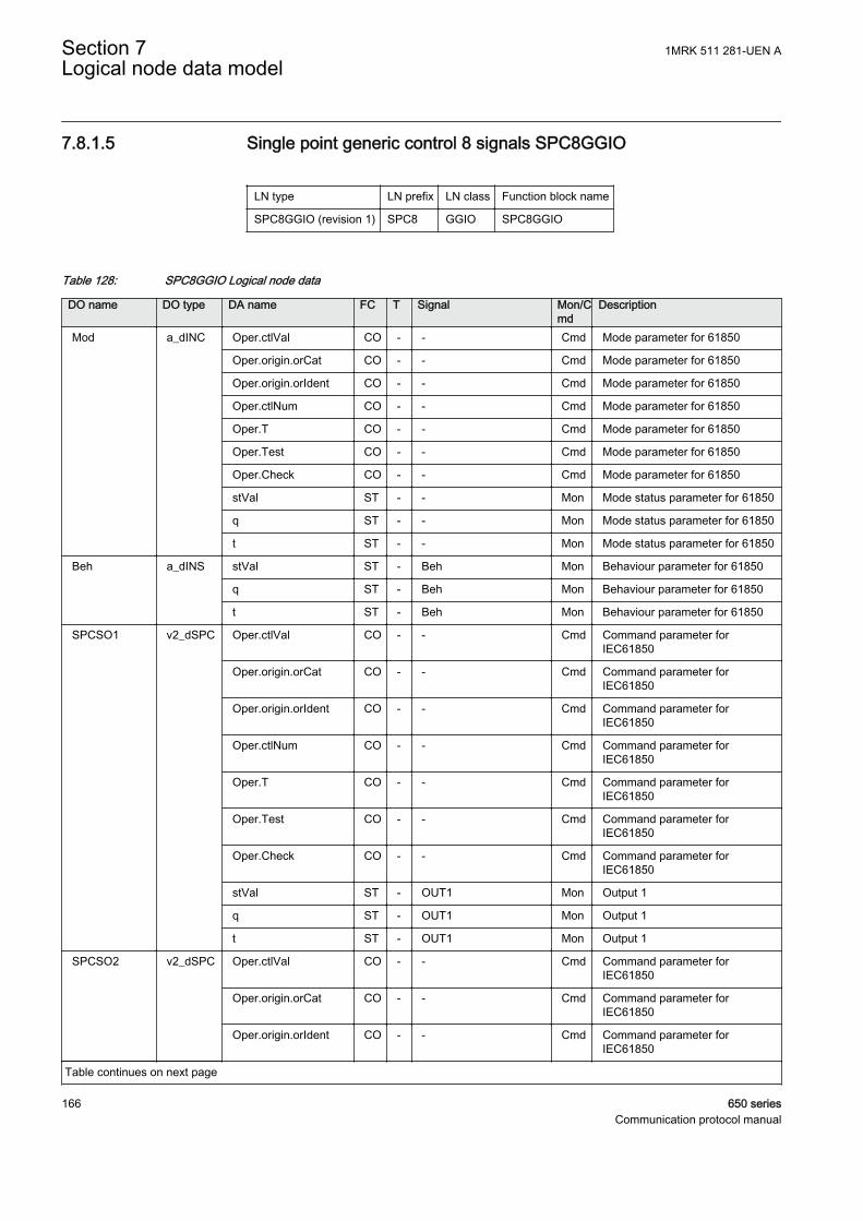
7.8.1.5 Single point generic control 8 signals SPC8GGIO
LN type LN prefix LN class Function block name
SPC8GGIO (revision 1) SPC8 GGIO SPC8GGIO
Table 128: SPC8GGIO Logical node data
DO name DO type DA name FC T Signal Mon/Cmd
Description
Mod a_dINC Oper.ctlVal CO - - Cmd Mode parameter for 61850
Oper.origin.orCat CO - - Cmd Mode parameter for 61850
Oper.origin.orIdent CO - - Cmd Mode parameter for 61850
Oper.ctlNum CO - - Cmd Mode parameter for 61850
Oper.T CO - - Cmd Mode parameter for 61850
Oper.Test CO - - Cmd Mode parameter for 61850
Oper.Check CO - - Cmd Mode parameter for 61850
stVal ST - - Mon Mode status parameter for 61850
q ST - - Mon Mode status parameter for 61850
t ST - - Mon Mode status parameter for 61850
Beh a_dINS stVal ST - Beh Mon Behaviour parameter for 61850
q ST - Beh Mon Behaviour parameter for 61850
t ST - Beh Mon Behaviour parameter for 61850
SPCSO1 v2_dSPC Oper.ctlVal CO - - Cmd Command parameter forIEC61850
Oper.origin.orCat CO - - Cmd Command parameter forIEC61850
Oper.origin.orIdent CO - - Cmd Command parameter forIEC61850
Oper.ctlNum CO - - Cmd Command parameter forIEC61850
Oper.T CO - - Cmd Command parameter forIEC61850
Oper.Test CO - - Cmd Command parameter forIEC61850
Oper.Check CO - - Cmd Command parameter forIEC61850
stVal ST - OUT1 Mon Output 1
q ST - OUT1 Mon Output 1
t ST - OUT1 Mon Output 1
SPCSO2 v2_dSPC Oper.ctlVal CO - - Cmd Command parameter forIEC61850
Oper.origin.orCat CO - - Cmd Command parameter forIEC61850
Oper.origin.orIdent CO - - Cmd Command parameter forIEC61850
Table continues on next page
Section 7 1MRK 511 281-UEN ALogical node data model
166 650 seriesCommunication protocol manual
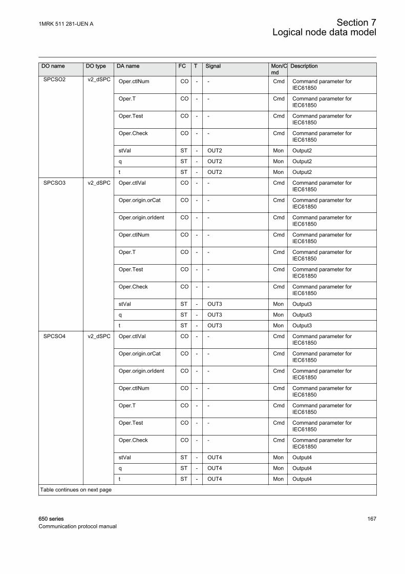
DO name DO type DA name FC T Signal Mon/Cmd
Description
SPCSO2 v2_dSPC Oper.ctlNum CO - - Cmd Command parameter forIEC61850
Oper.T CO - - Cmd Command parameter forIEC61850
Oper.Test CO - - Cmd Command parameter forIEC61850
Oper.Check CO - - Cmd Command parameter forIEC61850
stVal ST - OUT2 Mon Output2
q ST - OUT2 Mon Output2
t ST - OUT2 Mon Output2
SPCSO3 v2_dSPC Oper.ctlVal CO - - Cmd Command parameter forIEC61850
Oper.origin.orCat CO - - Cmd Command parameter forIEC61850
Oper.origin.orIdent CO - - Cmd Command parameter forIEC61850
Oper.ctlNum CO - - Cmd Command parameter forIEC61850
Oper.T CO - - Cmd Command parameter forIEC61850
Oper.Test CO - - Cmd Command parameter forIEC61850
Oper.Check CO - - Cmd Command parameter forIEC61850
stVal ST - OUT3 Mon Output3
q ST - OUT3 Mon Output3
t ST - OUT3 Mon Output3
SPCSO4 v2_dSPC Oper.ctlVal CO - - Cmd Command parameter forIEC61850
Oper.origin.orCat CO - - Cmd Command parameter forIEC61850
Oper.origin.orIdent CO - - Cmd Command parameter forIEC61850
Oper.ctlNum CO - - Cmd Command parameter forIEC61850
Oper.T CO - - Cmd Command parameter forIEC61850
Oper.Test CO - - Cmd Command parameter forIEC61850
Oper.Check CO - - Cmd Command parameter forIEC61850
stVal ST - OUT4 Mon Output4
q ST - OUT4 Mon Output4
t ST - OUT4 Mon Output4
Table continues on next page
1MRK 511 281-UEN A Section 7Logical node data model
650 series 167Communication protocol manual

DO name DO type DA name FC T Signal Mon/Cmd
Description
SPCSO5 v2_dSPC Oper.ctlVal CO - - Cmd Command parameter forIEC61850
Oper.origin.orCat CO - - Cmd Command parameter forIEC61850
Oper.origin.orIdent CO - - Cmd Command parameter forIEC61850
Oper.ctlNum CO - - Cmd Command parameter forIEC61850
Oper.T CO - - Cmd Command parameter forIEC61850
Oper.Test CO - - Cmd Command parameter forIEC61850
Oper.Check CO - - Cmd Command parameter forIEC61850
stVal ST - OUT5 Mon Output5
q ST - OUT5 Mon Output5
t ST - OUT5 Mon Output5
SPCSO6 v2_dSPC Oper.ctlVal CO - - Cmd Command parameter forIEC61850
Oper.origin.orCat CO - - Cmd Command parameter forIEC61850
Oper.origin.orIdent CO - - Cmd Command parameter forIEC61850
Oper.ctlNum CO - - Cmd Command parameter forIEC61850
Oper.T CO - - Cmd Command parameter forIEC61850
Oper.Test CO - - Cmd Command parameter forIEC61850
Oper.Check CO - - Cmd Command parameter forIEC61850
stVal ST - OUT6 Mon Output6
q ST - OUT6 Mon Output6
t ST - OUT6 Mon Output6
SPCSO7 v2_dSPC Oper.ctlVal CO - - Cmd Command parameter forIEC61850
Oper.origin.orCat CO - - Cmd Command parameter forIEC61850
Oper.origin.orIdent CO - - Cmd Command parameter forIEC61850
Oper.ctlNum CO - - Cmd Command parameter forIEC61850
Oper.T CO - - Cmd Command parameter forIEC61850
Oper.Test CO - - Cmd Command parameter forIEC61850
Table continues on next page
Section 7 1MRK 511 281-UEN ALogical node data model
168 650 seriesCommunication protocol manual
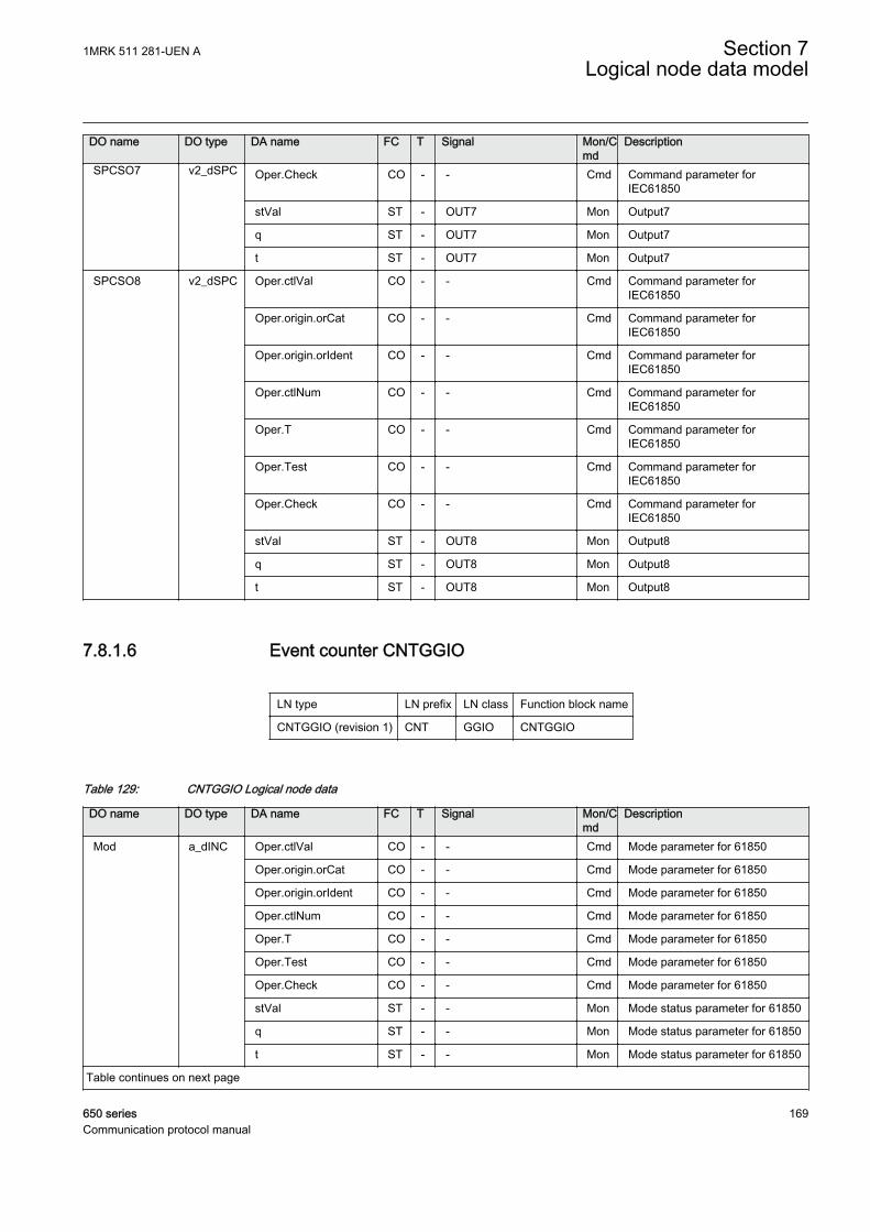
DO name DO type DA name FC T Signal Mon/Cmd
Description
SPCSO7 v2_dSPC Oper.Check CO - - Cmd Command parameter forIEC61850
stVal ST - OUT7 Mon Output7
q ST - OUT7 Mon Output7
t ST - OUT7 Mon Output7
SPCSO8 v2_dSPC Oper.ctlVal CO - - Cmd Command parameter forIEC61850
Oper.origin.orCat CO - - Cmd Command parameter forIEC61850
Oper.origin.orIdent CO - - Cmd Command parameter forIEC61850
Oper.ctlNum CO - - Cmd Command parameter forIEC61850
Oper.T CO - - Cmd Command parameter forIEC61850
Oper.Test CO - - Cmd Command parameter forIEC61850
Oper.Check CO - - Cmd Command parameter forIEC61850
stVal ST - OUT8 Mon Output8
q ST - OUT8 Mon Output8
t ST - OUT8 Mon Output8
7.8.1.6 Event counter CNTGGIO
LN type LN prefix LN class Function block name
CNTGGIO (revision 1) CNT GGIO CNTGGIO
Table 129: CNTGGIO Logical node data
DO name DO type DA name FC T Signal Mon/Cmd
Description
Mod a_dINC Oper.ctlVal CO - - Cmd Mode parameter for 61850
Oper.origin.orCat CO - - Cmd Mode parameter for 61850
Oper.origin.orIdent CO - - Cmd Mode parameter for 61850
Oper.ctlNum CO - - Cmd Mode parameter for 61850
Oper.T CO - - Cmd Mode parameter for 61850
Oper.Test CO - - Cmd Mode parameter for 61850
Oper.Check CO - - Cmd Mode parameter for 61850
stVal ST - - Mon Mode status parameter for 61850
q ST - - Mon Mode status parameter for 61850
t ST - - Mon Mode status parameter for 61850
Table continues on next page
1MRK 511 281-UEN A Section 7Logical node data model
650 series 169Communication protocol manual
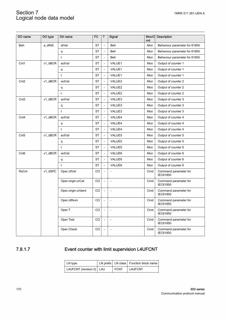
DO name DO type DA name FC T Signal Mon/Cmd
Description
Beh a_dINS stVal ST - Beh Mon Behaviour parameter for 61850
q ST - Beh Mon Behaviour parameter for 61850
t ST - Beh Mon Behaviour parameter for 61850
Cnt1 v1_dBCR actVal ST - VALUE1 Mon Output of counter 1
q ST - VALUE1 Mon Output of counter 1
t ST - VALUE1 Mon Output of counter 1
Cnt2 v1_dBCR actVal ST - VALUE2 Mon Output of counter 2
q ST - VALUE2 Mon Output of counter 2
t ST - VALUE2 Mon Output of counter 2
Cnt3 v1_dBCR actVal ST - VALUE3 Mon Output of counter 3
q ST - VALUE3 Mon Output of counter 3
t ST - VALUE3 Mon Output of counter 3
Cnt4 v1_dBCR actVal ST - VALUE4 Mon Output of counter 4
q ST - VALUE4 Mon Output of counter 4
t ST - VALUE4 Mon Output of counter 4
Cnt5 v1_dBCR actVal ST - VALUE5 Mon Output of counter 5
q ST - VALUE5 Mon Output of counter 5
t ST - VALUE5 Mon Output of counter 5
Cnt6 v1_dBCR actVal ST - VALUE6 Mon Output of counter 6
q ST - VALUE6 Mon Output of counter 6
t ST - VALUE6 Mon Output of counter 6
RsCnt v1_dSPC Oper.ctlVal CO - - Cmd Command parameter forIEC61850
Oper.origin.orCat CO - - Cmd Command parameter forIEC61850
Oper.origin.orIdent CO - - Cmd Command parameter forIEC61850
Oper.ctlNum CO - - Cmd Command parameter forIEC61850
Oper.T CO - - Cmd Command parameter forIEC61850
Oper.Test CO - - Cmd Command parameter forIEC61850
Oper.Check CO - - Cmd Command parameter forIEC61850
7.8.1.7 Event counter with limit supervision L4UFCNT
LN type LN prefix LN class Function block name
L4UFCNT (revision 0) L4U FCNT L4UFCNT
Section 7 1MRK 511 281-UEN ALogical node data model
170 650 seriesCommunication protocol manual
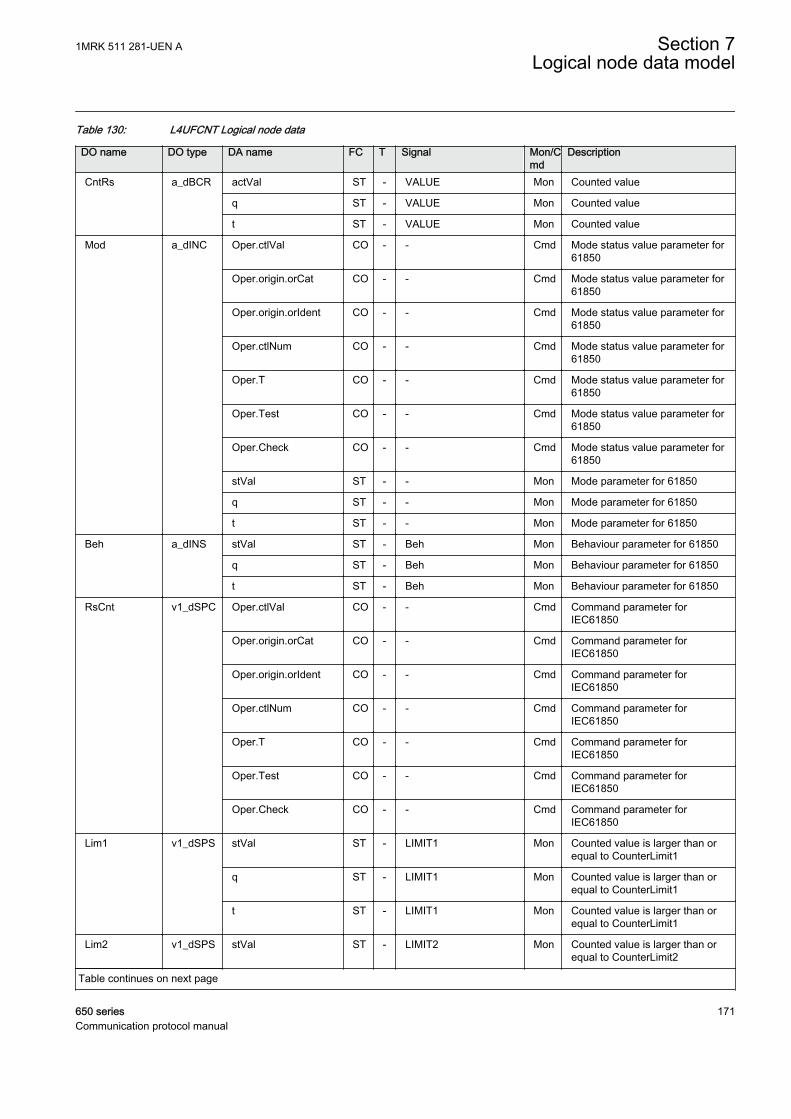
Table 130: L4UFCNT Logical node data
DO name DO type DA name FC T Signal Mon/Cmd
Description
CntRs a_dBCR actVal ST - VALUE Mon Counted value
q ST - VALUE Mon Counted value
t ST - VALUE Mon Counted value
Mod a_dINC Oper.ctlVal CO - - Cmd Mode status value parameter for61850
Oper.origin.orCat CO - - Cmd Mode status value parameter for61850
Oper.origin.orIdent CO - - Cmd Mode status value parameter for61850
Oper.ctlNum CO - - Cmd Mode status value parameter for61850
Oper.T CO - - Cmd Mode status value parameter for61850
Oper.Test CO - - Cmd Mode status value parameter for61850
Oper.Check CO - - Cmd Mode status value parameter for61850
stVal ST - - Mon Mode parameter for 61850
q ST - - Mon Mode parameter for 61850
t ST - - Mon Mode parameter for 61850
Beh a_dINS stVal ST - Beh Mon Behaviour parameter for 61850
q ST - Beh Mon Behaviour parameter for 61850
t ST - Beh Mon Behaviour parameter for 61850
RsCnt v1_dSPC Oper.ctlVal CO - - Cmd Command parameter forIEC61850
Oper.origin.orCat CO - - Cmd Command parameter forIEC61850
Oper.origin.orIdent CO - - Cmd Command parameter forIEC61850
Oper.ctlNum CO - - Cmd Command parameter forIEC61850
Oper.T CO - - Cmd Command parameter forIEC61850
Oper.Test CO - - Cmd Command parameter forIEC61850
Oper.Check CO - - Cmd Command parameter forIEC61850
Lim1 v1_dSPS stVal ST - LIMIT1 Mon Counted value is larger than orequal to CounterLimit1
q ST - LIMIT1 Mon Counted value is larger than orequal to CounterLimit1
t ST - LIMIT1 Mon Counted value is larger than orequal to CounterLimit1
Lim2 v1_dSPS stVal ST - LIMIT2 Mon Counted value is larger than orequal to CounterLimit2
Table continues on next page
1MRK 511 281-UEN A Section 7Logical node data model
650 series 171Communication protocol manual

DO name DO type DA name FC T Signal Mon/Cmd
Description
Lim2 v1_dSPS q ST - LIMIT2 Mon Counted value is larger than orequal to CounterLimit2
t ST - LIMIT2 Mon Counted value is larger than orequal to CounterLimit2
Lim3 v1_dSPS stVal ST - LIMIT3 Mon Counted value is larger than orequal to CounterLimit3
q ST - LIMIT3 Mon Counted value is larger than orequal to CounterLimit3
t ST - LIMIT3 Mon Counted value is larger than orequal to CounterLimit3
Lim4 v1_dSPS stVal ST - LIMIT4 Mon Counted value is larger than orequal to CounterLimit4
q ST - LIMIT4 Mon Counted value is larger than orequal to CounterLimit4
t ST - LIMIT4 Mon Counted value is larger than orequal to CounterLimit4
7.8.1.8 IEC61850 generic communication I/O functions SPGGIO
LN type LN prefix LN class Function block name
SPGGIO (revision 1) SP GGIO SPGGIO
Table 131: SPGGIO Logical node data
DO name DO type DA name FC T Signal Mon/Cmd
Description
Mod a_dINC Oper.ctlVal CO - - Cmd Mode parameter
Oper.origin.orCat CO - - Cmd Mode parameter
Oper.origin.orIdent CO - - Cmd Mode parameter
Oper.ctlNum CO - - Cmd Mode parameter
Oper.T CO - - Cmd Mode parameter
Oper.Test CO - - Cmd Mode parameter
Oper.Check CO - - Cmd Mode parameter
stVal ST - - Mon Mode status parameter for 61850
q ST - - Mon Mode status parameter for 61850
t ST - - Mon Mode status parameter for 61850
Beh a_dINS stVal ST - Beh Mon Behaviour parameter for 61850
q ST - Beh Mon Behaviour parameter for 61850
t ST - Beh Mon Behaviour parameter for 61850
Ind c_dSPS stVal ST - OUT Mon Output status
q ST - OUT Mon Output status
t ST - OUT Mon Output status
Section 7 1MRK 511 281-UEN ALogical node data model
172 650 seriesCommunication protocol manual
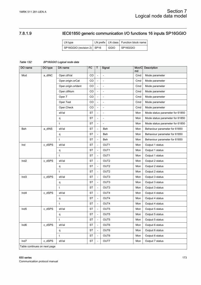
7.8.1.9 IEC61850 generic communication I/O functions 16 inputs SP16GGIO
LN type LN prefix LN class Function block name
SP16GGIO (revision 2) SP16 GGIO SP16GGIO
Table 132: SP16GGIO Logical node data
DO name DO type DA name FC T Signal Mon/Cmd
Description
Mod a_dINC Oper.ctlVal CO - - Cmd Mode parameter
Oper.origin.orCat CO - - Cmd Mode parameter
Oper.origin.orIdent CO - - Cmd Mode parameter
Oper.ctlNum CO - - Cmd Mode parameter
Oper.T CO - - Cmd Mode parameter
Oper.Test CO - - Cmd Mode parameter
Oper.Check CO - - Cmd Mode parameter
stVal ST - - Mon Mode status parameter for 61850
q ST - - Mon Mode status parameter for 61850
t ST - - Mon Mode status parameter for 61850
Beh a_dINS stVal ST - Beh Mon Behaviour parameter for 61850
q ST - Beh Mon Behaviour parameter for 61850
t ST - Beh Mon Behaviour parameter for 61850
Ind c_dSPS stVal ST - OUT1 Mon Output 1 status
q ST - OUT1 Mon Output 1 status
t ST - OUT1 Mon Output 1 status
Ind2 c_dSPS stVal ST - OUT2 Mon Output 2 status
q ST - OUT2 Mon Output 2 status
t ST - OUT2 Mon Output 2 status
Ind3 c_dSPS stVal ST - OUT3 Mon Output 3 status
q ST - OUT3 Mon Output 3 status
t ST - OUT3 Mon Output 3 status
Ind4 c_dSPS stVal ST - OUT4 Mon Output 4 status
q ST - OUT4 Mon Output 4 status
t ST - OUT4 Mon Output 4 status
Ind5 c_dSPS stVal ST - OUT5 Mon Output 5 status
q ST - OUT5 Mon Output 5 status
t ST - OUT5 Mon Output 5 status
Ind6 c_dSPS stVal ST - OUT6 Mon Output 6 status
q ST - OUT6 Mon Output 6 status
t ST - OUT6 Mon Output 6 status
Ind7 c_dSPS stVal ST - OUT7 Mon Output 7 status
Table continues on next page
1MRK 511 281-UEN A Section 7Logical node data model
650 series 173Communication protocol manual
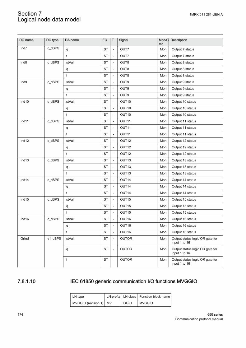
DO name DO type DA name FC T Signal Mon/Cmd
Description
Ind7 c_dSPS q ST - OUT7 Mon Output 7 status
t ST - OUT7 Mon Output 7 status
Ind8 c_dSPS stVal ST - OUT8 Mon Output 8 status
q ST - OUT8 Mon Output 8 status
t ST - OUT8 Mon Output 8 status
Ind9 c_dSPS stVal ST - OUT9 Mon Output 9 status
q ST - OUT9 Mon Output 9 status
t ST - OUT9 Mon Output 9 status
Ind10 c_dSPS stVal ST - OUT10 Mon Output 10 status
q ST - OUT10 Mon Output 10 status
t ST - OUT10 Mon Output 10 status
Ind11 c_dSPS stVal ST - OUT11 Mon Output 11 status
q ST - OUT11 Mon Output 11 status
t ST - OUT11 Mon Output 11 status
Ind12 c_dSPS stVal ST - OUT12 Mon Output 12 status
q ST - OUT12 Mon Output 12 status
t ST - OUT12 Mon Output 12 status
Ind13 c_dSPS stVal ST - OUT13 Mon Output 13 status
q ST - OUT13 Mon Output 13 status
t ST - OUT13 Mon Output 13 status
Ind14 c_dSPS stVal ST - OUT14 Mon Output 14 status
q ST - OUT14 Mon Output 14 status
t ST - OUT14 Mon Output 14 status
Ind15 c_dSPS stVal ST - OUT15 Mon Output 15 status
q ST - OUT15 Mon Output 15 status
t ST - OUT15 Mon Output 15 status
Ind16 c_dSPS stVal ST - OUT16 Mon Output 16 status
q ST - OUT16 Mon Output 16 status
t ST - OUT16 Mon Output 16 status
GrInd v1_dSPS stVal ST - OUTOR Mon Output status logic OR gate forinput 1 to 16
q ST - OUTOR Mon Output status logic OR gate forinput 1 to 16
t ST - OUTOR Mon Output status logic OR gate forinput 1 to 16
7.8.1.10 IEC 61850 generic communication I/O functions MVGGIO
LN type LN prefix LN class Function block name
MVGGIO (revision 1) MV GGIO MVGGIO
Section 7 1MRK 511 281-UEN ALogical node data model
174 650 seriesCommunication protocol manual
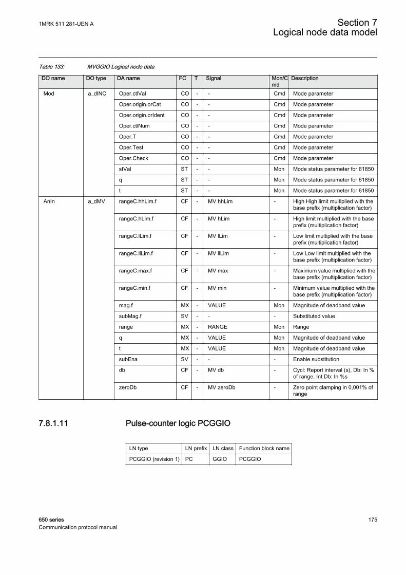
Table 133: MVGGIO Logical node data
DO name DO type DA name FC T Signal Mon/Cmd
Description
Mod a_dINC Oper.ctlVal CO - - Cmd Mode parameter
Oper.origin.orCat CO - - Cmd Mode parameter
Oper.origin.orIdent CO - - Cmd Mode parameter
Oper.ctlNum CO - - Cmd Mode parameter
Oper.T CO - - Cmd Mode parameter
Oper.Test CO - - Cmd Mode parameter
Oper.Check CO - - Cmd Mode parameter
stVal ST - - Mon Mode status parameter for 61850
q ST - - Mon Mode status parameter for 61850
t ST - - Mon Mode status parameter for 61850
AnIn a_dMV rangeC.hhLim.f CF - MV hhLim - High High limit multiplied with thebase prefix (multiplication factor)
rangeC.hLim.f CF - MV hLim - High limit multiplied with the baseprefix (multiplication factor)
rangeC.lLim.f CF - MV lLim - Low limit multiplied with the baseprefix (multiplication factor)
rangeC.llLim.f CF - MV llLim - Low Low limit multiplied with thebase prefix (multiplication factor)
rangeC.max.f CF - MV max - Maximum value multiplied with thebase prefix (multiplication factor)
rangeC.min.f CF - MV min - Minimum value multiplied with thebase prefix (multiplication factor)
mag.f MX - VALUE Mon Magnitude of deadband value
subMag.f SV - - - Substituted value
range MX - RANGE Mon Range
q MX - VALUE Mon Magnitude of deadband value
t MX - VALUE Mon Magnitude of deadband value
subEna SV - - - Enable substitution
db CF - MV db - Cycl: Report interval (s), Db: In %of range, Int Db: In %s
zeroDb CF - MV zeroDb - Zero point clamping in 0,001% ofrange
7.8.1.11 Pulse-counter logic PCGGIO
LN type LN prefix LN class Function block name
PCGGIO (revision 1) PC GGIO PCGGIO
1MRK 511 281-UEN A Section 7Logical node data model
650 series 175Communication protocol manual

Table 134: PCGGIO Logical node data
DO name DO type DA name FC T Signal Mon/Cmd
Description
Mod a_dINC Oper.ctlVal CO - - Cmd Mode parameter
Oper.origin.orCat CO - - Cmd Mode parameter
Oper.origin.orIdent CO - - Cmd Mode parameter
Oper.ctlNum CO - - Cmd Mode parameter
Oper.T CO - - Cmd Mode parameter
Oper.Test CO - - Cmd Mode parameter
Oper.Check CO - - Cmd Mode parameter
stVal ST - - Mon Mode status parameter for 61850
q ST - - Mon Mode status parameter for 61850
t ST - - Mon Mode status parameter for 61850
Beh a_dINS stVal ST - Beh Mon Behaviour parameter for 61850
q ST - Beh Mon Behaviour parameter for 61850
t ST - Beh Mon Behaviour parameter for 61850
AnIn b_dMV mag.f MX - SCAL_VAL Mon Scaled value with time and statusinformation
q MX - SCAL_VAL Mon Scaled value with time and statusinformation
t MX - SCAL_VAL Mon Scaled value with time and statusinformation
ValUpd v1_dSPS stVal ST - NEW_VAL Mon A new pulse counter value isgenerated
q ST - NEW_VAL Mon A new pulse counter value isgenerated
t ST - NEW_VAL Mon A new pulse counter value isgenerated
IcpCyc v1_dSPS stVal ST - RESTART Mon The reported value does notcomprise a complete integrationcycle
q ST - RESTART Mon The reported value does notcomprise a complete integrationcycle
t ST - RESTART Mon The reported value does notcomprise a complete integrationcycle
TotVal v2_dBCR actVal ST - CNT_VAL Mon Actual pulse counter value
q ST - CNT_VAL Mon Actual pulse counter value
t ST - CNT_VAL Mon Actual pulse counter value
7.8.1.12 Trip matrix logic TMAGGIO
LN type LN prefix LN class Function block name
TMAGGIO (revision 1) TMA GGIO TMAGGIO
Section 7 1MRK 511 281-UEN ALogical node data model
176 650 seriesCommunication protocol manual
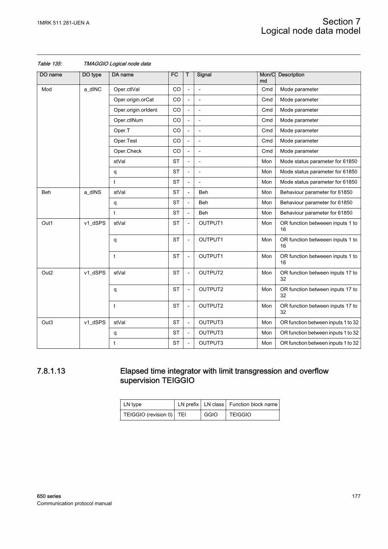
Table 135: TMAGGIO Logical node data
DO name DO type DA name FC T Signal Mon/Cmd
Description
Mod a_dINC Oper.ctlVal CO - - Cmd Mode parameter
Oper.origin.orCat CO - - Cmd Mode parameter
Oper.origin.orIdent CO - - Cmd Mode parameter
Oper.ctlNum CO - - Cmd Mode parameter
Oper.T CO - - Cmd Mode parameter
Oper.Test CO - - Cmd Mode parameter
Oper.Check CO - - Cmd Mode parameter
stVal ST - - Mon Mode status parameter for 61850
q ST - - Mon Mode status parameter for 61850
t ST - - Mon Mode status parameter for 61850
Beh a_dINS stVal ST - Beh Mon Behaviour parameter for 61850
q ST - Beh Mon Behaviour parameter for 61850
t ST - Beh Mon Behaviour parameter for 61850
Out1 v1_dSPS stVal ST - OUTPUT1 Mon OR function betweeen inputs 1 to16
q ST - OUTPUT1 Mon OR function betweeen inputs 1 to16
t ST - OUTPUT1 Mon OR function betweeen inputs 1 to16
Out2 v1_dSPS stVal ST - OUTPUT2 Mon OR function between inputs 17 to32
q ST - OUTPUT2 Mon OR function between inputs 17 to32
t ST - OUTPUT2 Mon OR function between inputs 17 to32
Out3 v1_dSPS stVal ST - OUTPUT3 Mon OR function between inputs 1 to 32
q ST - OUTPUT3 Mon OR function between inputs 1 to 32
t ST - OUTPUT3 Mon OR function between inputs 1 to 32
7.8.1.13 Elapsed time integrator with limit transgression and overflowsupervision TEIGGIO
LN type LN prefix LN class Function block name
TEIGGIO (revision 0) TEI GGIO TEIGGIO
1MRK 511 281-UEN A Section 7Logical node data model
650 series 177Communication protocol manual
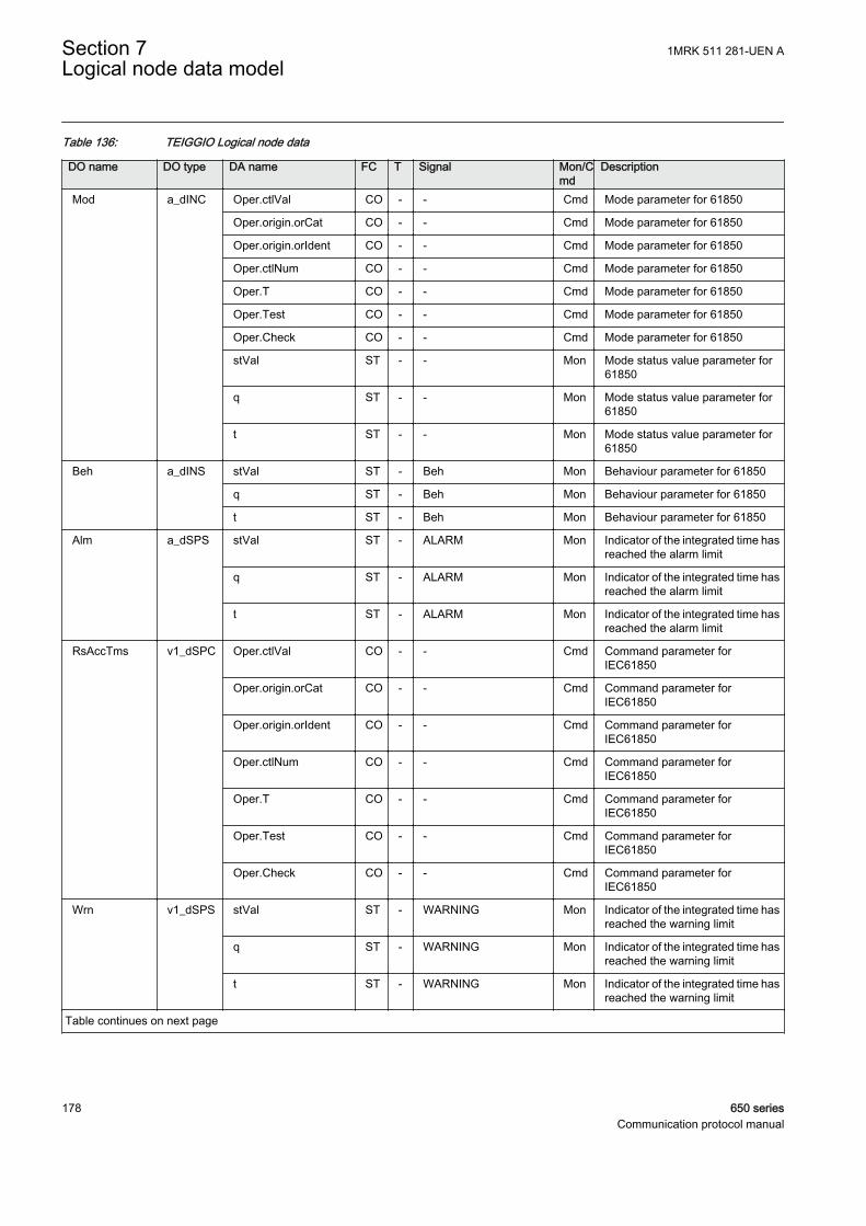
Table 136: TEIGGIO Logical node data
DO name DO type DA name FC T Signal Mon/Cmd
Description
Mod a_dINC Oper.ctlVal CO - - Cmd Mode parameter for 61850
Oper.origin.orCat CO - - Cmd Mode parameter for 61850
Oper.origin.orIdent CO - - Cmd Mode parameter for 61850
Oper.ctlNum CO - - Cmd Mode parameter for 61850
Oper.T CO - - Cmd Mode parameter for 61850
Oper.Test CO - - Cmd Mode parameter for 61850
Oper.Check CO - - Cmd Mode parameter for 61850
stVal ST - - Mon Mode status value parameter for61850
q ST - - Mon Mode status value parameter for61850
t ST - - Mon Mode status value parameter for61850
Beh a_dINS stVal ST - Beh Mon Behaviour parameter for 61850
q ST - Beh Mon Behaviour parameter for 61850
t ST - Beh Mon Behaviour parameter for 61850
Alm a_dSPS stVal ST - ALARM Mon Indicator of the integrated time hasreached the alarm limit
q ST - ALARM Mon Indicator of the integrated time hasreached the alarm limit
t ST - ALARM Mon Indicator of the integrated time hasreached the alarm limit
RsAccTms v1_dSPC Oper.ctlVal CO - - Cmd Command parameter forIEC61850
Oper.origin.orCat CO - - Cmd Command parameter forIEC61850
Oper.origin.orIdent CO - - Cmd Command parameter forIEC61850
Oper.ctlNum CO - - Cmd Command parameter forIEC61850
Oper.T CO - - Cmd Command parameter forIEC61850
Oper.Test CO - - Cmd Command parameter forIEC61850
Oper.Check CO - - Cmd Command parameter forIEC61850
Wrn v1_dSPS stVal ST - WARNING Mon Indicator of the integrated time hasreached the warning limit
q ST - WARNING Mon Indicator of the integrated time hasreached the warning limit
t ST - WARNING Mon Indicator of the integrated time hasreached the warning limit
Table continues on next page
Section 7 1MRK 511 281-UEN ALogical node data model
178 650 seriesCommunication protocol manual
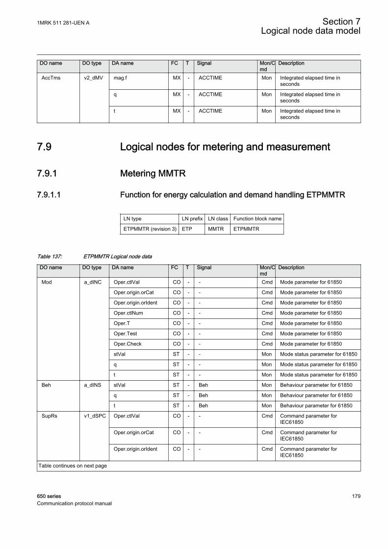
DO name DO type DA name FC T Signal Mon/Cmd
Description
AccTms v2_dMV mag.f MX - ACCTIME Mon Integrated elapsed time inseconds
q MX - ACCTIME Mon Integrated elapsed time inseconds
t MX - ACCTIME Mon Integrated elapsed time inseconds
7.9 Logical nodes for metering and measurement
7.9.1 Metering MMTR
7.9.1.1 Function for energy calculation and demand handling ETPMMTR
LN type LN prefix LN class Function block name
ETPMMTR (revision 3) ETP MMTR ETPMMTR
Table 137: ETPMMTR Logical node data
DO name DO type DA name FC T Signal Mon/Cmd
Description
Mod a_dINC Oper.ctlVal CO - - Cmd Mode parameter for 61850
Oper.origin.orCat CO - - Cmd Mode parameter for 61850
Oper.origin.orIdent CO - - Cmd Mode parameter for 61850
Oper.ctlNum CO - - Cmd Mode parameter for 61850
Oper.T CO - - Cmd Mode parameter for 61850
Oper.Test CO - - Cmd Mode parameter for 61850
Oper.Check CO - - Cmd Mode parameter for 61850
stVal ST - - Mon Mode status parameter for 61850
q ST - - Mon Mode status parameter for 61850
t ST - - Mon Mode status parameter for 61850
Beh a_dINS stVal ST - Beh Mon Behaviour parameter for 61850
q ST - Beh Mon Behaviour parameter for 61850
t ST - Beh Mon Behaviour parameter for 61850
SupRs v1_dSPC Oper.ctlVal CO - - Cmd Command parameter forIEC61850
Oper.origin.orCat CO - - Cmd Command parameter forIEC61850
Oper.origin.orIdent CO - - Cmd Command parameter forIEC61850
Table continues on next page
1MRK 511 281-UEN A Section 7Logical node data model
650 series 179Communication protocol manual

DO name DO type DA name FC T Signal Mon/Cmd
Description
SupRs v1_dSPC Oper.ctlNum CO - - Cmd Command parameter forIEC61850
Oper.T CO - - Cmd Command parameter forIEC61850
Oper.Test CO - - Cmd Command parameter forIEC61850
Oper.Check CO - - Cmd Command parameter forIEC61850
MaxDmdRs v1_dSPC Oper.ctlVal CO - - Cmd Command parameter forIEC61850
Oper.origin.orCat CO - - Cmd Command parameter forIEC61850
Oper.origin.orIdent CO - - Cmd Command parameter forIEC61850
Oper.ctlNum CO - - Cmd Command parameter forIEC61850
Oper.T CO - - Cmd Command parameter forIEC61850
Oper.Test CO - - Cmd Command parameter forIEC61850
Oper.Check CO - - Cmd Command parameter forIEC61850
StrAcc v1_dSPS stVal ST - ACCST Mon Start of accumulating energyvalues
q ST - ACCST Mon Start of accumulating energyvalues
t ST - ACCST Mon Start of accumulating energyvalues
WhFwdAlm v1_dSPS stVal ST - EAFALM Mon Alarm for active forward energyexceed limit in set interval
q ST - EAFALM Mon Alarm for active forward energyexceed limit in set interval
t ST - EAFALM Mon Alarm for active forward energyexceed limit in set interval
WhRvAlm v1_dSPS stVal ST - EARALM Mon Alarm for active reverse energyexceed limit in set interval
q ST - EARALM Mon Alarm for active reverse energyexceed limit in set interval
t ST - EARALM Mon Alarm for active reverse energyexceed limit in set interval
VArhFwdAlm v1_dSPS stVal ST - ERFALM Mon Alarm for reactive forward energyexceed limit in set interval
q ST - ERFALM Mon Alarm for reactive forward energyexceed limit in set interval
t ST - ERFALM Mon Alarm for reactive forward energyexceed limit in set interval
VArhRvAlm v1_dSPS stVal ST - ERRALM Mon Alarm for reactive reverse energyexceed limit in set interval
Table continues on next page
Section 7 1MRK 511 281-UEN ALogical node data model
180 650 seriesCommunication protocol manual
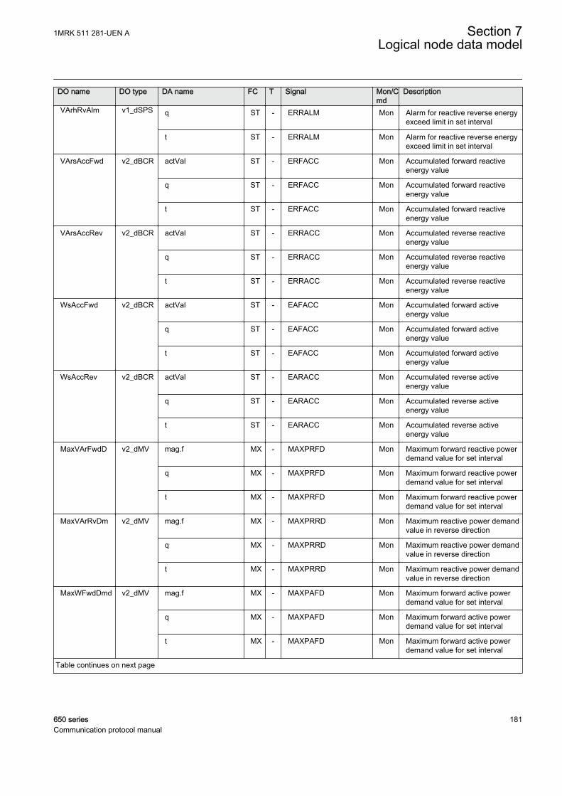
DO name DO type DA name FC T Signal Mon/Cmd
Description
VArhRvAlm v1_dSPS q ST - ERRALM Mon Alarm for reactive reverse energyexceed limit in set interval
t ST - ERRALM Mon Alarm for reactive reverse energyexceed limit in set interval
VArsAccFwd v2_dBCR actVal ST - ERFACC Mon Accumulated forward reactiveenergy value
q ST - ERFACC Mon Accumulated forward reactiveenergy value
t ST - ERFACC Mon Accumulated forward reactiveenergy value
VArsAccRev v2_dBCR actVal ST - ERRACC Mon Accumulated reverse reactiveenergy value
q ST - ERRACC Mon Accumulated reverse reactiveenergy value
t ST - ERRACC Mon Accumulated reverse reactiveenergy value
WsAccFwd v2_dBCR actVal ST - EAFACC Mon Accumulated forward activeenergy value
q ST - EAFACC Mon Accumulated forward activeenergy value
t ST - EAFACC Mon Accumulated forward activeenergy value
WsAccRev v2_dBCR actVal ST - EARACC Mon Accumulated reverse activeenergy value
q ST - EARACC Mon Accumulated reverse activeenergy value
t ST - EARACC Mon Accumulated reverse activeenergy value
MaxVArFwdD v2_dMV mag.f MX - MAXPRFD Mon Maximum forward reactive powerdemand value for set interval
q MX - MAXPRFD Mon Maximum forward reactive powerdemand value for set interval
t MX - MAXPRFD Mon Maximum forward reactive powerdemand value for set interval
MaxVArRvDm v2_dMV mag.f MX - MAXPRRD Mon Maximum reactive power demandvalue in reverse direction
q MX - MAXPRRD Mon Maximum reactive power demandvalue in reverse direction
t MX - MAXPRRD Mon Maximum reactive power demandvalue in reverse direction
MaxWFwdDmd v2_dMV mag.f MX - MAXPAFD Mon Maximum forward active powerdemand value for set interval
q MX - MAXPAFD Mon Maximum forward active powerdemand value for set interval
t MX - MAXPAFD Mon Maximum forward active powerdemand value for set interval
Table continues on next page
1MRK 511 281-UEN A Section 7Logical node data model
650 series 181Communication protocol manual
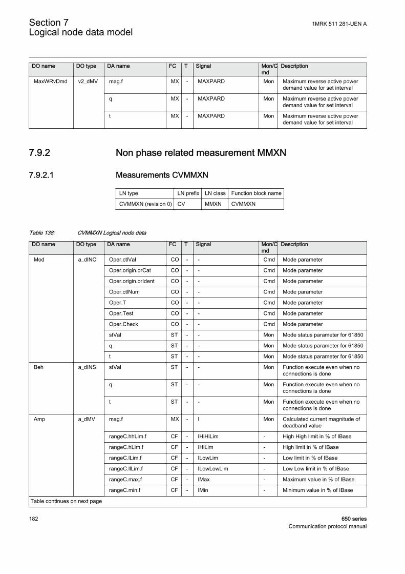
DO name DO type DA name FC T Signal Mon/Cmd
Description
MaxWRvDmd v2_dMV mag.f MX - MAXPARD Mon Maximum reverse active powerdemand value for set interval
q MX - MAXPARD Mon Maximum reverse active powerdemand value for set interval
t MX - MAXPARD Mon Maximum reverse active powerdemand value for set interval
7.9.2 Non phase related measurement MMXN
7.9.2.1 Measurements CVMMXN
LN type LN prefix LN class Function block name
CVMMXN (revision 0) CV MMXN CVMMXN
Table 138: CVMMXN Logical node data
DO name DO type DA name FC T Signal Mon/Cmd
Description
Mod a_dINC Oper.ctlVal CO - - Cmd Mode parameter
Oper.origin.orCat CO - - Cmd Mode parameter
Oper.origin.orIdent CO - - Cmd Mode parameter
Oper.ctlNum CO - - Cmd Mode parameter
Oper.T CO - - Cmd Mode parameter
Oper.Test CO - - Cmd Mode parameter
Oper.Check CO - - Cmd Mode parameter
stVal ST - - Mon Mode status parameter for 61850
q ST - - Mon Mode status parameter for 61850
t ST - - Mon Mode status parameter for 61850
Beh a_dINS stVal ST - - Mon Function execute even when noconnections is done
q ST - - Mon Function execute even when noconnections is done
t ST - - Mon Function execute even when noconnections is done
Amp a_dMV mag.f MX - I Mon Calculated current magnitude ofdeadband value
rangeC.hhLim.f CF - IHiHiLim - High High limit in % of IBase
rangeC.hLim.f CF - IHiLim - High limit in % of IBase
rangeC.lLim.f CF - ILowLim - Low limit in % of IBase
rangeC.llLim.f CF - ILowLowLim - Low Low limit in % of IBase
rangeC.max.f CF - IMax - Maximum value in % of IBase
rangeC.min.f CF - IMin - Minimum value in % of IBase
Table continues on next page
Section 7 1MRK 511 281-UEN ALogical node data model
182 650 seriesCommunication protocol manual

DO name DO type DA name FC T Signal Mon/Cmd
Description
Amp a_dMV subMag.f SV - - - Substituted value
range MX - I_RANGE Mon Calculated current range
q MX - I Mon Calculated current magnitude ofdeadband value
t MX - I Mon Calculated current magnitude ofdeadband value
subEna SV - - - Enable substitution
db CF - IDbRepInt - Cycl: Report interval (s), Db: In %of range, Int Db: In %s
zeroDb CF - IZeroDb - Zero point clamping
Hz a_dMV mag.f MX - F Mon System frequency magnitude ofdeadband value
rangeC.hhLim.f CF - FrHiHiLim - High High limit (physical value)
rangeC.hLim.f CF - FrHiLim - High limit (physical value)
rangeC.lLim.f CF - FrLowLim - Low limit (physical value)
rangeC.llLim.f CF - FrLowLowLim - Low Low limit (physical value)
rangeC.max.f CF - FrMax - Maximum value
rangeC.min.f CF - FrMin - Minimum value
subMag.f SV - - - Substituted value
range MX - F_RANGE Mon System frequency range
q MX - F Mon System frequency magnitude ofdeadband value
t MX - F Mon System frequency magnitude ofdeadband value
subEna SV - - - Enable substitution
db CF - FrDbRepInt - Cycl: Report interval (s), Db: In %of range, Int Db: In %s
zeroDb CF - FrZeroDb - Zero point clamping
PwrFact a_dMV rangeC.hhLim.f CF - PFHiHiLim - High High limit (physical value)
rangeC.hLim.f CF - PFHiLim - High limit (physical value)
rangeC.lLim.f CF - PFLowLim - Low limit (physical value)
rangeC.llLim.f CF - PFLowLowLim - Low Low limit (physical value)
rangeC.max.f CF - PFMax - Maximum value
rangeC.min.f CF - PFMin - Minimum value
mag.f MX - PF Mon Power factor magnitude ofdeadband value
subMag.f SV - - - Substituted value
range MX - PF_RANGE Mon Power factor range
q MX - PF Mon Power factor magnitude ofdeadband value
t MX - PF Mon Power factor magnitude ofdeadband value
subEna SV - - - Enable substitution
Table continues on next page
1MRK 511 281-UEN A Section 7Logical node data model
650 series 183Communication protocol manual
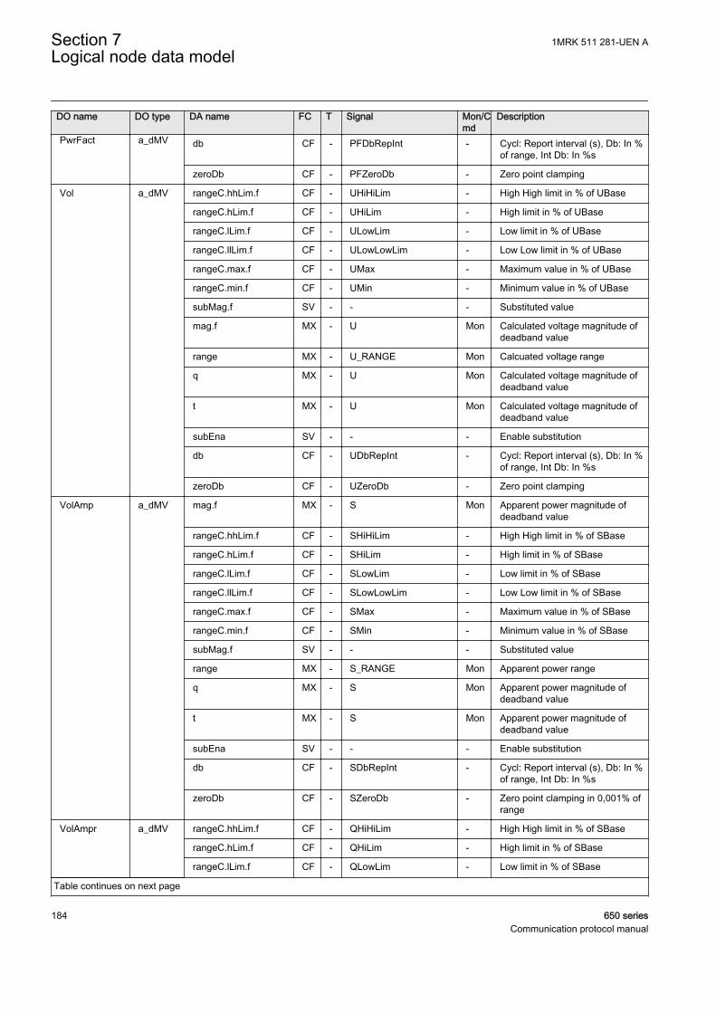
DO name DO type DA name FC T Signal Mon/Cmd
Description
PwrFact a_dMV db CF - PFDbRepInt - Cycl: Report interval (s), Db: In %of range, Int Db: In %s
zeroDb CF - PFZeroDb - Zero point clamping
Vol a_dMV rangeC.hhLim.f CF - UHiHiLim - High High limit in % of UBase
rangeC.hLim.f CF - UHiLim - High limit in % of UBase
rangeC.lLim.f CF - ULowLim - Low limit in % of UBase
rangeC.llLim.f CF - ULowLowLim - Low Low limit in % of UBase
rangeC.max.f CF - UMax - Maximum value in % of UBase
rangeC.min.f CF - UMin - Minimum value in % of UBase
subMag.f SV - - - Substituted value
mag.f MX - U Mon Calculated voltage magnitude ofdeadband value
range MX - U_RANGE Mon Calcuated voltage range
q MX - U Mon Calculated voltage magnitude ofdeadband value
t MX - U Mon Calculated voltage magnitude ofdeadband value
subEna SV - - - Enable substitution
db CF - UDbRepInt - Cycl: Report interval (s), Db: In %of range, Int Db: In %s
zeroDb CF - UZeroDb - Zero point clamping
VolAmp a_dMV mag.f MX - S Mon Apparent power magnitude ofdeadband value
rangeC.hhLim.f CF - SHiHiLim - High High limit in % of SBase
rangeC.hLim.f CF - SHiLim - High limit in % of SBase
rangeC.lLim.f CF - SLowLim - Low limit in % of SBase
rangeC.llLim.f CF - SLowLowLim - Low Low limit in % of SBase
rangeC.max.f CF - SMax - Maximum value in % of SBase
rangeC.min.f CF - SMin - Minimum value in % of SBase
subMag.f SV - - - Substituted value
range MX - S_RANGE Mon Apparent power range
q MX - S Mon Apparent power magnitude ofdeadband value
t MX - S Mon Apparent power magnitude ofdeadband value
subEna SV - - - Enable substitution
db CF - SDbRepInt - Cycl: Report interval (s), Db: In %of range, Int Db: In %s
zeroDb CF - SZeroDb - Zero point clamping in 0,001% ofrange
VolAmpr a_dMV rangeC.hhLim.f CF - QHiHiLim - High High limit in % of SBase
rangeC.hLim.f CF - QHiLim - High limit in % of SBase
rangeC.lLim.f CF - QLowLim - Low limit in % of SBase
Table continues on next page
Section 7 1MRK 511 281-UEN ALogical node data model
184 650 seriesCommunication protocol manual

DO name DO type DA name FC T Signal Mon/Cmd
Description
VolAmpr a_dMV rangeC.llLim.f CF - QLowLowLim - Low Low limit in % of SBase
rangeC.max.f CF - QMax - Maximum value in % of SBase
rangeC.min.f CF - QMin - Minimum value in % of SBase
mag.f MX - Q Mon Reactive power magnitude ofdeadband value
subMag.f SV - - - Substituted value
range MX - Q_RANGE Mon Reactive power range
q MX - Q Mon Reactive power magnitude ofdeadband value
t MX - Q Mon Reactive power magnitude ofdeadband value
subEna SV - - - Enable substitution
db CF - QDbRepInt - Cycl: Report interval (s), Db: In %of range, Int Db: In %s
zeroDb CF - QZeroDb - Zero point clamping
Watt a_dMV mag.f MX - P Mon Active power magnitude ofdeadband value
rangeC.hhLim.f CF - PHiHiLim - High High limit in % of SBase
rangeC.hLim.f CF - PHiLim - High limit in % of SBase
rangeC.lLim.f CF - PLowLim - Low limit in % of SBase
rangeC.llLim.f CF - PLowLowLim - Low Low limit in % of SBase
rangeC.max.f CF - PMax - Maximum value in % of SBase
rangeC.min.f CF - PMin - Minimum value in % of SBase
subMag.f SV - - - Substituted value
range MX - P_RANGE Mon Active power range
q MX - P Mon Active power magnitude ofdeadband value
t MX - P Mon Active power magnitude ofdeadband value
subEna SV - - - Enable substitution
db CF - PDbRepInt - Cycl: Report interval (s), Db: In %of range, Int Db: In %s
zeroDb CF - PZeroDb - Zero point clamping
ALd v1_dSPS stVal ST - ILEAD Mon Current is leading voltage
q ST - ILEAD Mon Current is leading voltage
t ST - ILEAD Mon Current is leading voltage
ALg v1_dSPS stVal ST - ILAG Mon Current is lagging voltage
q ST - ILAG Mon Current is lagging voltage
t ST - ILAG Mon Current is lagging voltage
1MRK 511 281-UEN A Section 7Logical node data model
650 series 185Communication protocol manual
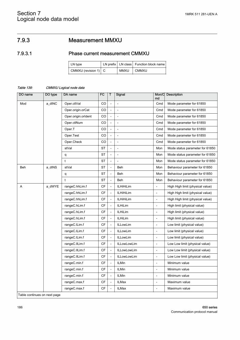
7.9.3 Measurement MMXU
7.9.3.1 Phase current measurement CMMXU
LN type LN prefix LN class Function block name
CMMXU (revision 1) C MMXU CMMXU
Table 139: CMMXU Logical node data
DO name DO type DA name FC T Signal Mon/Cmd
Description
Mod a_dINC Oper.ctlVal CO - - Cmd Mode parameter for 61850
Oper.origin.orCat CO - - Cmd Mode parameter for 61850
Oper.origin.orIdent CO - - Cmd Mode parameter for 61850
Oper.ctlNum CO - - Cmd Mode parameter for 61850
Oper.T CO - - Cmd Mode parameter for 61850
Oper.Test CO - - Cmd Mode parameter for 61850
Oper.Check CO - - Cmd Mode parameter for 61850
stVal ST - - Mon Mode status parameter for 61850
q ST - - Mon Mode status parameter for 61850
t ST - - Mon Mode status parameter for 61850
Beh a_dINS stVal ST - Beh Mon Behaviour parameter for 61850
q ST - Beh Mon Behaviour parameter for 61850
t ST - Beh Mon Behaviour parameter for 61850
A a_dWYE rangeC.hhLim.f CF - ILHiHiLim - High High limit (physical value)
rangeC.hhLim.f CF - ILHiHiLim - High High limit (physical value)
rangeC.hhLim.f CF - ILHiHiLim - High High limit (physical value)
rangeC.hLim.f CF - ILHiLim - High limit (physical value)
rangeC.hLim.f CF - ILHiLim - High limit (physical value)
rangeC.hLim.f CF - ILHiLim - High limit (physical value)
rangeC.lLim.f CF - ILLowLim - Low limit (physical value)
rangeC.lLim.f CF - ILLowLim - Low limit (physical value)
rangeC.lLim.f CF - ILLowLim - Low limit (physical value)
rangeC.llLim.f CF - ILLowLowLim - Low Low limit (physical value)
rangeC.llLim.f CF - ILLowLowLim - Low Low limit (physical value)
rangeC.llLim.f CF - ILLowLowLim - Low Low limit (physical value)
rangeC.min.f CF - ILMin - Minimum value
rangeC.min.f CF - ILMin - Minimum value
rangeC.min.f CF - ILMin - Minimum value
rangeC.max.f CF - ILMax - Maximum value
rangeC.max.f CF - ILMax - Maximum value
Table continues on next page
Section 7 1MRK 511 281-UEN ALogical node data model
186 650 seriesCommunication protocol manual
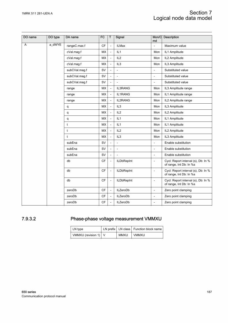
DO name DO type DA name FC T Signal Mon/Cmd
Description
A a_dWYE rangeC.max.f CF - ILMax - Maximum value
cVal.mag.f MX - IL1 Mon IL1 Amplitude
cVal.mag.f MX - IL2 Mon IL2 Amplitude
cVal.mag.f MX - IL3 Mon IL3 Amplitude
subCVal.mag.f SV - - - Substituted value
subCVal.mag.f SV - - - Substituted value
subCVal.mag.f SV - - - Substituted value
range MX - IL3RANG Mon IL3 Amplitude range
range MX - IL1RANG Mon IL1 Amplitude range
range MX - IL2RANG Mon IL2 Amplitude range
q MX - IL3 Mon IL3 Amplitude
q MX - IL2 Mon IL2 Amplitude
q MX - IL1 Mon IL1 Amplitude
t MX - IL1 Mon IL1 Amplitude
t MX - IL2 Mon IL2 Amplitude
t MX - IL3 Mon IL3 Amplitude
subEna SV - - - Enable substitution
subEna SV - - - Enable substitution
subEna SV - - - Enable substitution
db CF - ILDbRepInt - Cycl: Report interval (s), Db: In %of range, Int Db: In %s
db CF - ILDbRepInt - Cycl: Report interval (s), Db: In %of range, Int Db: In %s
db CF - ILDbRepInt - Cycl: Report interval (s), Db: In %of range, Int Db: In %s
zeroDb CF - ILZeroDb - Zero point clamping
zeroDb CF - ILZeroDb - Zero point clamping
zeroDb CF - ILZeroDb - Zero point clamping
7.9.3.2 Phase-phase voltage measurement VMMXU
LN type LN prefix LN class Function block name
VMMXU (revision 1) V MMXU VMMXU
1MRK 511 281-UEN A Section 7Logical node data model
650 series 187Communication protocol manual
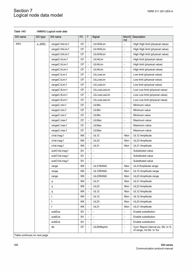
Table 140: VMMXU Logical node data
DO name DO type DA name FC T Signal Mon/Cmd
Description
PPV a_dDEL rangeC.hhLim.f CF - ULHiHiLim - High High limit (physical value)
rangeC.hhLim.f CF - ULHiHiLim - High High limit (physical value)
rangeC.hhLim.f CF - ULHiHiLim - High High limit (physical value)
rangeC.hLim.f CF - ULHiLim - High limit (physical value)
rangeC.hLim.f CF - ULHiLim - High limit (physical value)
rangeC.hLim.f CF - ULHiLim - High limit (physical value)
rangeC.lLim.f CF - ULLowLim - Low limit (physical value)
rangeC.lLim.f CF - ULLowLim - Low limit (physical value)
rangeC.lLim.f CF - ULLowLim - Low limit (physical value)
rangeC.llLim.f CF - ULLowLowLim - Low Low limit (physical value)
rangeC.llLim.f CF - ULLowLowLim - Low Low limit (physical value)
rangeC.llLim.f CF - ULLowLowLim - Low Low limit (physical value)
rangeC.min.f CF - ULMin - Minimum value
rangeC.min.f CF - ULMin - Minimum value
rangeC.min.f CF - ULMin - Minimum value
rangeC.max.f CF - ULMax - Maximum value
rangeC.max.f CF - ULMax - Maximum value
rangeC.max.f CF - ULMax - Maximum value
cVal.mag.f MX - UL12 Mon UL12 Amplitude
cVal.mag.f MX - UL23 Mon UL23 Amplitude
cVal.mag.f MX - UL31 Mon UL31 Amplitude
subCVal.mag.f SV - - - Substituted value
subCVal.mag.f SV - - - Substituted value
subCVal.mag.f SV - - - Substituted value
range MX - UL31RANG Mon UL31Amplitude range
range MX - UL12RANG Mon UL12 Amplitude range
range MX - UL23RANG Mon UL23 Amplitude range
q MX - UL31 Mon UL31 Amplitude
q MX - UL23 Mon UL23 Amplitude
q MX - UL12 Mon UL12 Amplitude
t MX - UL12 Mon UL12 Amplitude
t MX - UL23 Mon UL23 Amplitude
t MX - UL31 Mon UL31 Amplitude
subEna SV - - - Enable substitution
subEna SV - - - Enable substitution
subEna SV - - - Enable substitution
db CF - ULDbRepInt - Cycl: Report interval (s), Db: In %of range, Int Db: In %s
Table continues on next page
Section 7 1MRK 511 281-UEN ALogical node data model
188 650 seriesCommunication protocol manual
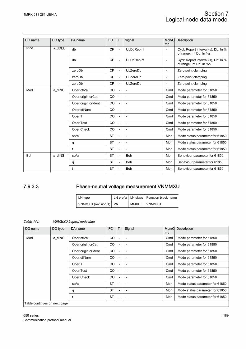
DO name DO type DA name FC T Signal Mon/Cmd
Description
PPV a_dDEL db CF - ULDbRepInt - Cycl: Report interval (s), Db: In %of range, Int Db: In %s
db CF - ULDbRepInt - Cycl: Report interval (s), Db: In %of range, Int Db: In %s
zeroDb CF - ULZeroDb - Zero point clamping
zeroDb CF - ULZeroDb - Zero point clamping
zeroDb CF - ULZeroDb - Zero point clamping
Mod a_dINC Oper.ctlVal CO - - Cmd Mode parameter for 61850
Oper.origin.orCat CO - - Cmd Mode parameter for 61850
Oper.origin.orIdent CO - - Cmd Mode parameter for 61850
Oper.ctlNum CO - - Cmd Mode parameter for 61850
Oper.T CO - - Cmd Mode parameter for 61850
Oper.Test CO - - Cmd Mode parameter for 61850
Oper.Check CO - - Cmd Mode parameter for 61850
stVal ST - - Mon Mode status parameter for 61850
q ST - - Mon Mode status parameter for 61850
t ST - - Mon Mode status parameter for 61850
Beh a_dINS stVal ST - Beh Mon Behaviour parameter for 61850
q ST - Beh Mon Behaviour parameter for 61850
t ST - Beh Mon Behaviour parameter for 61850
7.9.3.3 Phase-neutral voltage measurement VNMMXU
LN type LN prefix LN class Function block name
VNMMXU (revision 1) VN MMXU VNMMXU
Table 141: VNMMXU Logical node data
DO name DO type DA name FC T Signal Mon/Cmd
Description
Mod a_dINC Oper.ctlVal CO - - Cmd Mode parameter for 61850
Oper.origin.orCat CO - - Cmd Mode parameter for 61850
Oper.origin.orIdent CO - - Cmd Mode parameter for 61850
Oper.ctlNum CO - - Cmd Mode parameter for 61850
Oper.T CO - - Cmd Mode parameter for 61850
Oper.Test CO - - Cmd Mode parameter for 61850
Oper.Check CO - - Cmd Mode parameter for 61850
stVal ST - - Mon Mode status parameter for 61850
q ST - - Mon Mode status parameter for 61850
t ST - - Mon Mode status parameter for 61850
Table continues on next page
1MRK 511 281-UEN A Section 7Logical node data model
650 series 189Communication protocol manual

DO name DO type DA name FC T Signal Mon/Cmd
Description
Beh a_dINS stVal ST - Beh Mon Behaviour parameter for 61850
q ST - Beh Mon Behaviour parameter for 61850
t ST - Beh Mon Behaviour parameter for 61850
PhV a_dWYE cVal.mag.f MX - UL1 Mon UL1 Amplitude, magnitude ofreported value
cVal.mag.f MX - UL2 Mon UL2 Amplitude, magnitude ofreported value
cVal.mag.f MX - UL3 Mon UL3 Amplitude, magnitude ofreported value
subCVal.mag.f SV - - - Substituted value
subCVal.mag.f SV - - - Substituted value
rangeC.hhLim.f CF - UHiHiLim - High High limit (physical value)
rangeC.hhLim.f CF - UHiHiLim - High High limit (physical value)
rangeC.hhLim.f CF - UHiHiLim - High High limit (physical value)
rangeC.hLim.f CF - UHiLim - High limit (physical value)
rangeC.hLim.f CF - UHiLim - High limit (physical value)
rangeC.hLim.f CF - UHiLim - High limit (physical value)
rangeC.lLim.f CF - ULowLim - Low limit (physical value)
rangeC.lLim.f CF - ULowLim - Low limit (physical value)
rangeC.lLim.f CF - ULowLim - Low limit (physical value)
rangeC.llLim.f CF - ULowLowLim - Low Low limit (physical value)
rangeC.llLim.f CF - ULowLowLim - Low Low limit (physical value)
rangeC.llLim.f CF - ULowLowLim - Low Low limit (physical value)
rangeC.min.f CF - UMin - Minimum value
rangeC.min.f CF - UMin - Minimum value
rangeC.min.f CF - UMin - Minimum value
rangeC.max.f CF - UMax - Maximum value
rangeC.max.f CF - UMax - Maximum value
rangeC.max.f CF - UMax - Maximum value
subCVal.mag.f SV - - - Substituted value
range MX - UL3RANG Mon UL3 Amplitude range
range MX - UL1RANG Mon UL1 Amplitude range
range MX - UL2RANG Mon UL2 Amplitude range
q MX - UL3 Mon UL3 Amplitude, magnitude ofreported value
q MX - UL2 Mon UL2 Amplitude, magnitude ofreported value
q MX - UL1 Mon UL1 Amplitude, magnitude ofreported value
t MX - UL1 Mon UL1 Amplitude, magnitude ofreported value
Table continues on next page
Section 7 1MRK 511 281-UEN ALogical node data model
190 650 seriesCommunication protocol manual
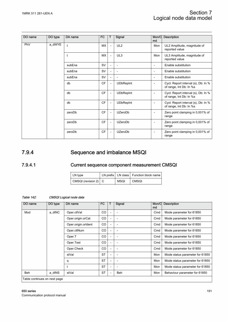
DO name DO type DA name FC T Signal Mon/Cmd
Description
PhV a_dWYE t MX - UL2 Mon UL2 Amplitude, magnitude ofreported value
t MX - UL3 Mon UL3 Amplitude, magnitude ofreported value
subEna SV - - - Enable substitution
subEna SV - - - Enable substitution
subEna SV - - - Enable substitution
db CF - UDbRepInt - Cycl: Report interval (s), Db: In %of range, Int Db: In %s
db CF - UDbRepInt - Cycl: Report interval (s), Db: In %of range, Int Db: In %s
db CF - UDbRepInt - Cycl: Report interval (s), Db: In %of range, Int Db: In %s
zeroDb CF - UZeroDb - Zero point clamping in 0,001% ofrange
zeroDb CF - UZeroDb - Zero point clamping in 0,001% ofrange
zeroDb CF - UZeroDb - Zero point clamping in 0,001% ofrange
7.9.4 Sequence and imbalance MSQI
7.9.4.1 Current sequence component measurement CMSQI
LN type LN prefix LN class Function block name
CMSQI (revision 2) C MSQI CMSQI
Table 142: CMSQI Logical node data
DO name DO type DA name FC T Signal Mon/Cmd
Description
Mod a_dINC Oper.ctlVal CO - - Cmd Mode parameter for 61850
Oper.origin.orCat CO - - Cmd Mode parameter for 61850
Oper.origin.orIdent CO - - Cmd Mode parameter for 61850
Oper.ctlNum CO - - Cmd Mode parameter for 61850
Oper.T CO - - Cmd Mode parameter for 61850
Oper.Test CO - - Cmd Mode parameter for 61850
Oper.Check CO - - Cmd Mode parameter for 61850
stVal ST - - Mon Mode status parameter for 61850
q ST - - Mon Mode status parameter for 61850
t ST - - Mon Mode status parameter for 61850
Beh a_dINS stVal ST - Beh Mon Behaviour parameter for 61850
Table continues on next page
1MRK 511 281-UEN A Section 7Logical node data model
650 series 191Communication protocol manual
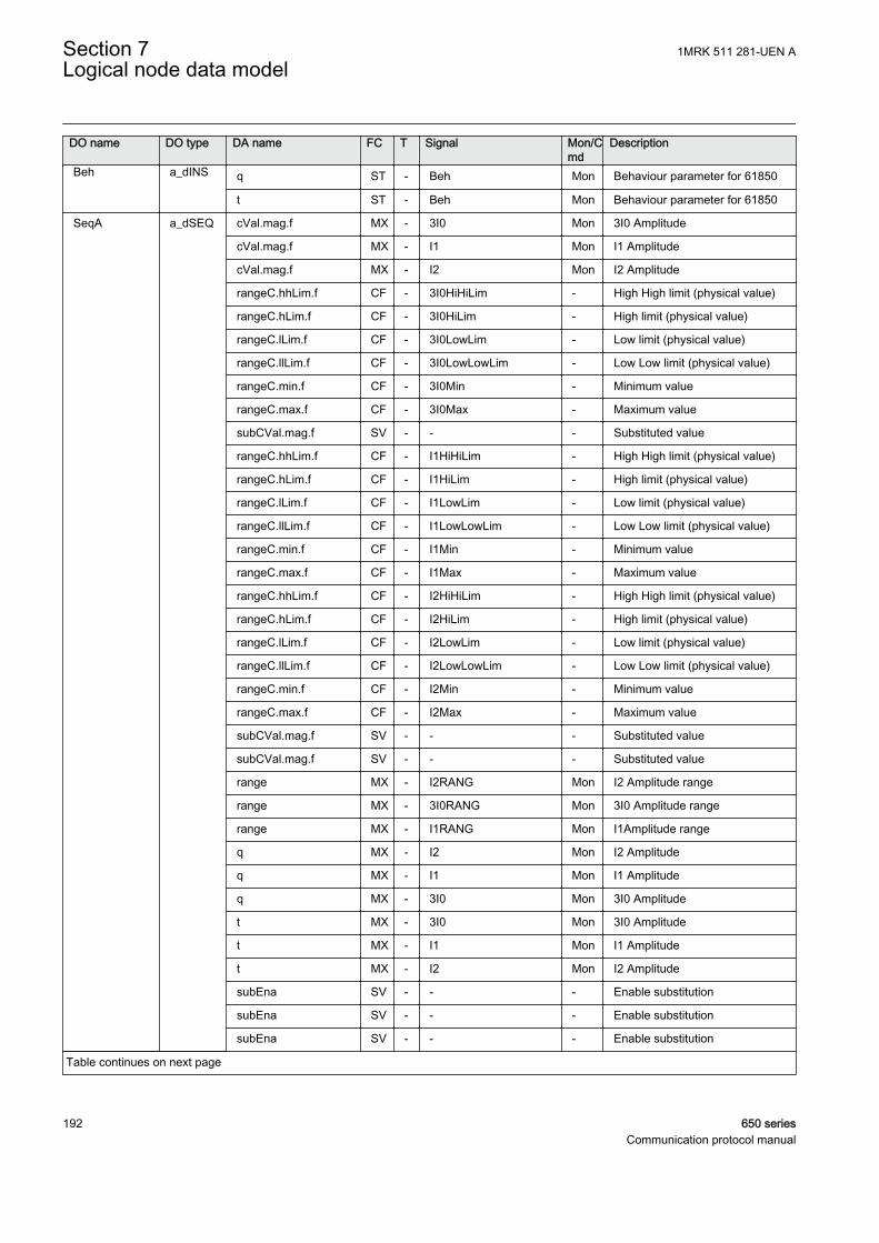
DO name DO type DA name FC T Signal Mon/Cmd
Description
Beh a_dINS q ST - Beh Mon Behaviour parameter for 61850
t ST - Beh Mon Behaviour parameter for 61850
SeqA a_dSEQ cVal.mag.f MX - 3I0 Mon 3I0 Amplitude
cVal.mag.f MX - I1 Mon I1 Amplitude
cVal.mag.f MX - I2 Mon I2 Amplitude
rangeC.hhLim.f CF - 3I0HiHiLim - High High limit (physical value)
rangeC.hLim.f CF - 3I0HiLim - High limit (physical value)
rangeC.lLim.f CF - 3I0LowLim - Low limit (physical value)
rangeC.llLim.f CF - 3I0LowLowLim - Low Low limit (physical value)
rangeC.min.f CF - 3I0Min - Minimum value
rangeC.max.f CF - 3I0Max - Maximum value
subCVal.mag.f SV - - - Substituted value
rangeC.hhLim.f CF - I1HiHiLim - High High limit (physical value)
rangeC.hLim.f CF - I1HiLim - High limit (physical value)
rangeC.lLim.f CF - I1LowLim - Low limit (physical value)
rangeC.llLim.f CF - I1LowLowLim - Low Low limit (physical value)
rangeC.min.f CF - I1Min - Minimum value
rangeC.max.f CF - I1Max - Maximum value
rangeC.hhLim.f CF - I2HiHiLim - High High limit (physical value)
rangeC.hLim.f CF - I2HiLim - High limit (physical value)
rangeC.lLim.f CF - I2LowLim - Low limit (physical value)
rangeC.llLim.f CF - I2LowLowLim - Low Low limit (physical value)
rangeC.min.f CF - I2Min - Minimum value
rangeC.max.f CF - I2Max - Maximum value
subCVal.mag.f SV - - - Substituted value
subCVal.mag.f SV - - - Substituted value
range MX - I2RANG Mon I2 Amplitude range
range MX - 3I0RANG Mon 3I0 Amplitude range
range MX - I1RANG Mon I1Amplitude range
q MX - I2 Mon I2 Amplitude
q MX - I1 Mon I1 Amplitude
q MX - 3I0 Mon 3I0 Amplitude
t MX - 3I0 Mon 3I0 Amplitude
t MX - I1 Mon I1 Amplitude
t MX - I2 Mon I2 Amplitude
subEna SV - - - Enable substitution
subEna SV - - - Enable substitution
subEna SV - - - Enable substitution
Table continues on next page
Section 7 1MRK 511 281-UEN ALogical node data model
192 650 seriesCommunication protocol manual
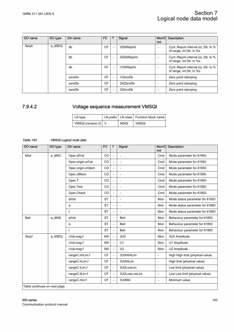
DO name DO type DA name FC T Signal Mon/Cmd
Description
SeqA a_dSEQ db CF - I2DbRepInt - Cycl: Report interval (s), Db: In %of range, Int Db: In %s
db CF - 3I0DbRepInt - Cycl: Report interval (s), Db: In %of range, Int Db: In %s
db CF - I1DbRepInt - Cycl: Report interval (s), Db: In %of range, Int Db: In %s
zeroDb CF - I1ZeroDb - Zero point clamping
zeroDb CF - 3I0ZeroDb - Zero point clamping
zeroDb CF - I2ZeroDb - Zero point clamping
7.9.4.2 Voltage sequence measurement VMSQI
LN type LN prefix LN class Function block name
VMSQI (revision 2) V MSQI VMSQI
Table 143: VMSQI Logical node data
DO name DO type DA name FC T Signal Mon/Cmd
Description
Mod a_dINC Oper.ctlVal CO - - Cmd Mode parameter for 61850
Oper.origin.orCat CO - - Cmd Mode parameter for 61850
Oper.origin.orIdent CO - - Cmd Mode parameter for 61850
Oper.ctlNum CO - - Cmd Mode parameter for 61850
Oper.T CO - - Cmd Mode parameter for 61850
Oper.Test CO - - Cmd Mode parameter for 61850
Oper.Check CO - - Cmd Mode parameter for 61850
stVal ST - - Mon Mode status parameter for 61850
q ST - - Mon Mode status parameter for 61850
t ST - - Mon Mode status parameter for 61850
Beh a_dINS stVal ST - Beh Mon Behaviour parameter for 61850
q ST - Beh Mon Behaviour parameter for 61850
t ST - Beh Mon Behaviour parameter for 61850
SeqV a_dSEQ cVal.mag.f MX - 3U0 Mon 3U0 Amplitude
cVal.mag.f MX - U1 Mon U1 Amplitude
cVal.mag.f MX - U2 Mon U2 Amplitude
rangeC.hhLim.f CF - 3U0HiHiLim - High High limit (physical value)
rangeC.hLim.f CF - 3U0HiLim - High limit (physical value)
rangeC.lLim.f CF - 3U0LowLim - Low limit (physical value)
rangeC.llLim.f CF - 3U0LowLowLim - Low Low limit (physical value)
rangeC.min.f CF - 3U0Min - Minimum value
Table continues on next page
1MRK 511 281-UEN A Section 7Logical node data model
650 series 193Communication protocol manual
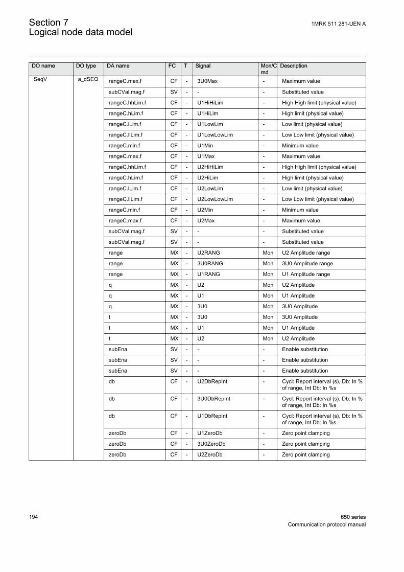
DO name DO type DA name FC T Signal Mon/Cmd
Description
SeqV a_dSEQ rangeC.max.f CF - 3U0Max - Maximum value
subCVal.mag.f SV - - - Substituted value
rangeC.hhLim.f CF - U1HiHiLim - High High limit (physical value)
rangeC.hLim.f CF - U1HiLim - High limit (physical value)
rangeC.lLim.f CF - U1LowLim - Low limit (physical value)
rangeC.llLim.f CF - U1LowLowLim - Low Low limit (physical value)
rangeC.min.f CF - U1Min - Minimum value
rangeC.max.f CF - U1Max - Maximum value
rangeC.hhLim.f CF - U2HiHiLim - High High limit (physical value)
rangeC.hLim.f CF - U2HiLim - High limit (physical value)
rangeC.lLim.f CF - U2LowLim - Low limit (physical value)
rangeC.llLim.f CF - U2LowLowLim - Low Low limit (physical value)
rangeC.min.f CF - U2Min - Minimum value
rangeC.max.f CF - U2Max - Maximum value
subCVal.mag.f SV - - - Substituted value
subCVal.mag.f SV - - - Substituted value
range MX - U2RANG Mon U2 Amplitude range
range MX - 3U0RANG Mon 3U0 Amplitude range
range MX - U1RANG Mon U1 Amplitude range
q MX - U2 Mon U2 Amplitude
q MX - U1 Mon U1 Amplitude
q MX - 3U0 Mon 3U0 Amplitude
t MX - 3U0 Mon 3U0 Amplitude
t MX - U1 Mon U1 Amplitude
t MX - U2 Mon U2 Amplitude
subEna SV - - - Enable substitution
subEna SV - - - Enable substitution
subEna SV - - - Enable substitution
db CF - U2DbRepInt - Cycl: Report interval (s), Db: In %of range, Int Db: In %s
db CF - 3U0DbRepInt - Cycl: Report interval (s), Db: In %of range, Int Db: In %s
db CF - U1DbRepInt - Cycl: Report interval (s), Db: In %of range, Int Db: In %s
zeroDb CF - U1ZeroDb - Zero point clamping
zeroDb CF - 3U0ZeroDb - Zero point clamping
zeroDb CF - U2ZeroDb - Zero point clamping
Section 7 1MRK 511 281-UEN ALogical node data model
194 650 seriesCommunication protocol manual
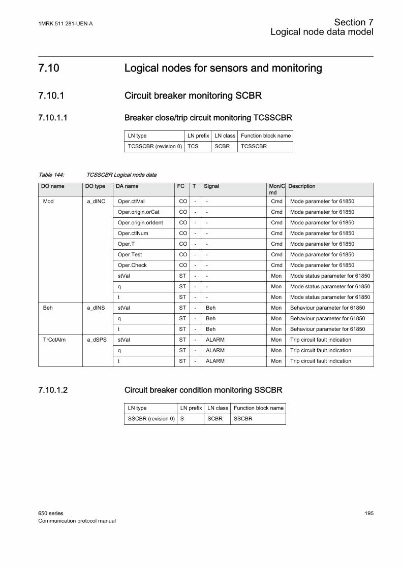
7.10 Logical nodes for sensors and monitoring
7.10.1 Circuit breaker monitoring SCBR
7.10.1.1 Breaker close/trip circuit monitoring TCSSCBR
LN type LN prefix LN class Function block name
TCSSCBR (revision 0) TCS SCBR TCSSCBR
Table 144: TCSSCBR Logical node data
DO name DO type DA name FC T Signal Mon/Cmd
Description
Mod a_dINC Oper.ctlVal CO - - Cmd Mode parameter for 61850
Oper.origin.orCat CO - - Cmd Mode parameter for 61850
Oper.origin.orIdent CO - - Cmd Mode parameter for 61850
Oper.ctlNum CO - - Cmd Mode parameter for 61850
Oper.T CO - - Cmd Mode parameter for 61850
Oper.Test CO - - Cmd Mode parameter for 61850
Oper.Check CO - - Cmd Mode parameter for 61850
stVal ST - - Mon Mode status parameter for 61850
q ST - - Mon Mode status parameter for 61850
t ST - - Mon Mode status parameter for 61850
Beh a_dINS stVal ST - Beh Mon Behaviour parameter for 61850
q ST - Beh Mon Behaviour parameter for 61850
t ST - Beh Mon Behaviour parameter for 61850
TrCctAlm a_dSPS stVal ST - ALARM Mon Trip circuit fault indication
q ST - ALARM Mon Trip circuit fault indication
t ST - ALARM Mon Trip circuit fault indication
7.10.1.2 Circuit breaker condition monitoring SSCBR
LN type LN prefix LN class Function block name
SSCBR (revision 0) S SCBR SSCBR
1MRK 511 281-UEN A Section 7Logical node data model
650 series 195Communication protocol manual
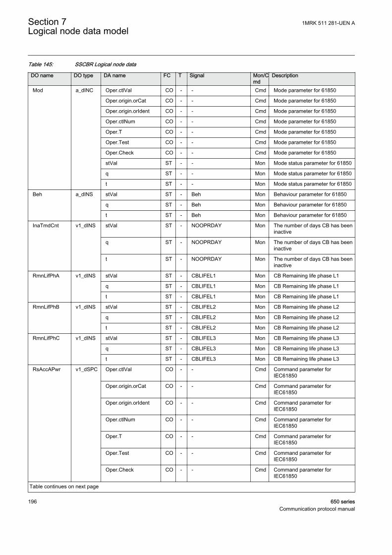
Table 145: SSCBR Logical node data
DO name DO type DA name FC T Signal Mon/Cmd
Description
Mod a_dINC Oper.ctlVal CO - - Cmd Mode parameter for 61850
Oper.origin.orCat CO - - Cmd Mode parameter for 61850
Oper.origin.orIdent CO - - Cmd Mode parameter for 61850
Oper.ctlNum CO - - Cmd Mode parameter for 61850
Oper.T CO - - Cmd Mode parameter for 61850
Oper.Test CO - - Cmd Mode parameter for 61850
Oper.Check CO - - Cmd Mode parameter for 61850
stVal ST - - Mon Mode status parameter for 61850
q ST - - Mon Mode status parameter for 61850
t ST - - Mon Mode status parameter for 61850
Beh a_dINS stVal ST - Beh Mon Behaviour parameter for 61850
q ST - Beh Mon Behaviour parameter for 61850
t ST - Beh Mon Behaviour parameter for 61850
InaTmdCnt v1_dINS stVal ST - NOOPRDAY Mon The number of days CB has beeninactive
q ST - NOOPRDAY Mon The number of days CB has beeninactive
t ST - NOOPRDAY Mon The number of days CB has beeninactive
RmnLifPhA v1_dINS stVal ST - CBLIFEL1 Mon CB Remaining life phase L1
q ST - CBLIFEL1 Mon CB Remaining life phase L1
t ST - CBLIFEL1 Mon CB Remaining life phase L1
RmnLifPhB v1_dINS stVal ST - CBLIFEL2 Mon CB Remaining life phase L2
q ST - CBLIFEL2 Mon CB Remaining life phase L2
t ST - CBLIFEL2 Mon CB Remaining life phase L2
RmnLifPhC v1_dINS stVal ST - CBLIFEL3 Mon CB Remaining life phase L3
q ST - CBLIFEL3 Mon CB Remaining life phase L3
t ST - CBLIFEL3 Mon CB Remaining life phase L3
RsAccAPwr v1_dSPC Oper.ctlVal CO - - Cmd Command parameter forIEC61850
Oper.origin.orCat CO - - Cmd Command parameter forIEC61850
Oper.origin.orIdent CO - - Cmd Command parameter forIEC61850
Oper.ctlNum CO - - Cmd Command parameter forIEC61850
Oper.T CO - - Cmd Command parameter forIEC61850
Oper.Test CO - - Cmd Command parameter forIEC61850
Oper.Check CO - - Cmd Command parameter forIEC61850
Table continues on next page
Section 7 1MRK 511 281-UEN ALogical node data model
196 650 seriesCommunication protocol manual
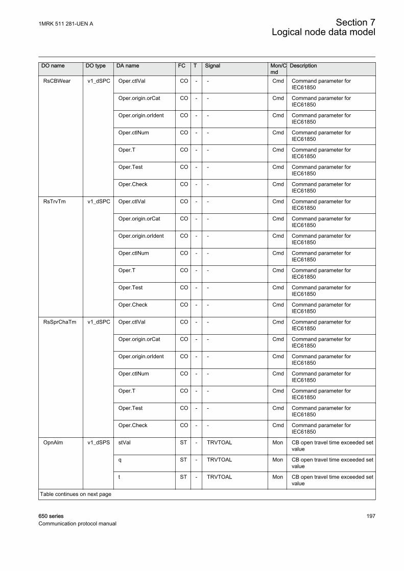
DO name DO type DA name FC T Signal Mon/Cmd
Description
RsCBWear v1_dSPC Oper.ctlVal CO - - Cmd Command parameter forIEC61850
Oper.origin.orCat CO - - Cmd Command parameter forIEC61850
Oper.origin.orIdent CO - - Cmd Command parameter forIEC61850
Oper.ctlNum CO - - Cmd Command parameter forIEC61850
Oper.T CO - - Cmd Command parameter forIEC61850
Oper.Test CO - - Cmd Command parameter forIEC61850
Oper.Check CO - - Cmd Command parameter forIEC61850
RsTrvTm v1_dSPC Oper.ctlVal CO - - Cmd Command parameter forIEC61850
Oper.origin.orCat CO - - Cmd Command parameter forIEC61850
Oper.origin.orIdent CO - - Cmd Command parameter forIEC61850
Oper.ctlNum CO - - Cmd Command parameter forIEC61850
Oper.T CO - - Cmd Command parameter forIEC61850
Oper.Test CO - - Cmd Command parameter forIEC61850
Oper.Check CO - - Cmd Command parameter forIEC61850
RsSprChaTm v1_dSPC Oper.ctlVal CO - - Cmd Command parameter forIEC61850
Oper.origin.orCat CO - - Cmd Command parameter forIEC61850
Oper.origin.orIdent CO - - Cmd Command parameter forIEC61850
Oper.ctlNum CO - - Cmd Command parameter forIEC61850
Oper.T CO - - Cmd Command parameter forIEC61850
Oper.Test CO - - Cmd Command parameter forIEC61850
Oper.Check CO - - Cmd Command parameter forIEC61850
OpnAlm v1_dSPS stVal ST - TRVTOAL Mon CB open travel time exceeded setvalue
q ST - TRVTOAL Mon CB open travel time exceeded setvalue
t ST - TRVTOAL Mon CB open travel time exceeded setvalue
Table continues on next page
1MRK 511 281-UEN A Section 7Logical node data model
650 series 197Communication protocol manual
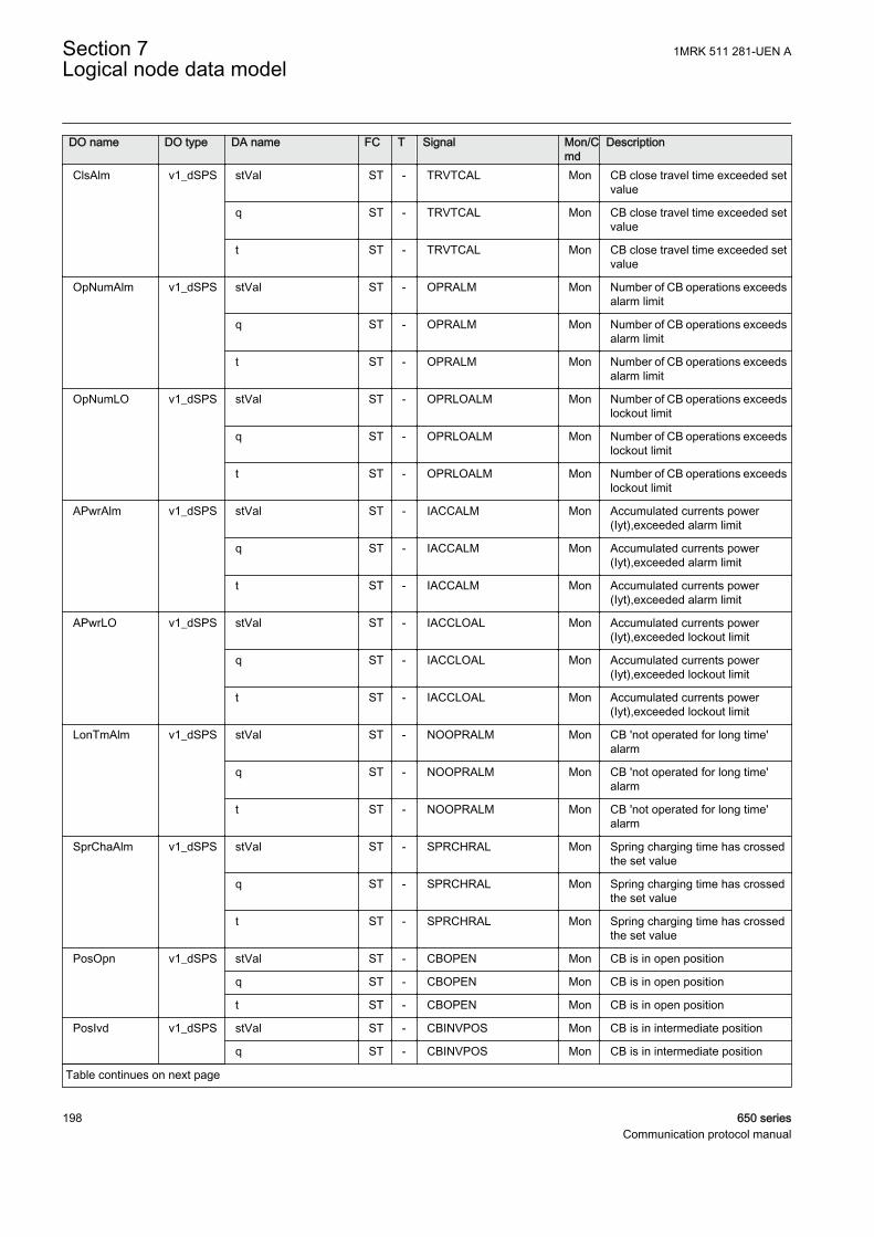
DO name DO type DA name FC T Signal Mon/Cmd
Description
ClsAlm v1_dSPS stVal ST - TRVTCAL Mon CB close travel time exceeded setvalue
q ST - TRVTCAL Mon CB close travel time exceeded setvalue
t ST - TRVTCAL Mon CB close travel time exceeded setvalue
OpNumAlm v1_dSPS stVal ST - OPRALM Mon Number of CB operations exceedsalarm limit
q ST - OPRALM Mon Number of CB operations exceedsalarm limit
t ST - OPRALM Mon Number of CB operations exceedsalarm limit
OpNumLO v1_dSPS stVal ST - OPRLOALM Mon Number of CB operations exceedslockout limit
q ST - OPRLOALM Mon Number of CB operations exceedslockout limit
t ST - OPRLOALM Mon Number of CB operations exceedslockout limit
APwrAlm v1_dSPS stVal ST - IACCALM Mon Accumulated currents power(Iyt),exceeded alarm limit
q ST - IACCALM Mon Accumulated currents power(Iyt),exceeded alarm limit
t ST - IACCALM Mon Accumulated currents power(Iyt),exceeded alarm limit
APwrLO v1_dSPS stVal ST - IACCLOAL Mon Accumulated currents power(Iyt),exceeded lockout limit
q ST - IACCLOAL Mon Accumulated currents power(Iyt),exceeded lockout limit
t ST - IACCLOAL Mon Accumulated currents power(Iyt),exceeded lockout limit
LonTmAlm v1_dSPS stVal ST - NOOPRALM Mon CB 'not operated for long time'alarm
q ST - NOOPRALM Mon CB 'not operated for long time'alarm
t ST - NOOPRALM Mon CB 'not operated for long time'alarm
SprChaAlm v1_dSPS stVal ST - SPRCHRAL Mon Spring charging time has crossedthe set value
q ST - SPRCHRAL Mon Spring charging time has crossedthe set value
t ST - SPRCHRAL Mon Spring charging time has crossedthe set value
PosOpn v1_dSPS stVal ST - CBOPEN Mon CB is in open position
q ST - CBOPEN Mon CB is in open position
t ST - CBOPEN Mon CB is in open position
PosIvd v1_dSPS stVal ST - CBINVPOS Mon CB is in intermediate position
q ST - CBINVPOS Mon CB is in intermediate position
Table continues on next page
Section 7 1MRK 511 281-UEN ALogical node data model
198 650 seriesCommunication protocol manual
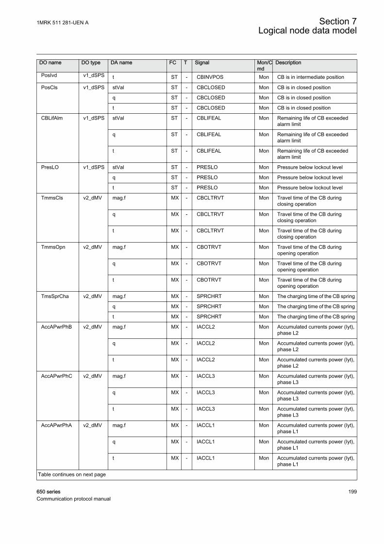
DO name DO type DA name FC T Signal Mon/Cmd
Description
PosIvd v1_dSPS t ST - CBINVPOS Mon CB is in intermediate position
PosCls v1_dSPS stVal ST - CBCLOSED Mon CB is in closed position
q ST - CBCLOSED Mon CB is in closed position
t ST - CBCLOSED Mon CB is in closed position
CBLifAlm v1_dSPS stVal ST - CBLIFEAL Mon Remaining life of CB exceededalarm limit
q ST - CBLIFEAL Mon Remaining life of CB exceededalarm limit
t ST - CBLIFEAL Mon Remaining life of CB exceededalarm limit
PresLO v1_dSPS stVal ST - PRESLO Mon Pressure below lockout level
q ST - PRESLO Mon Pressure below lockout level
t ST - PRESLO Mon Pressure below lockout level
TmmsCls v2_dMV mag.f MX - CBCLTRVT Mon Travel time of the CB duringclosing operation
q MX - CBCLTRVT Mon Travel time of the CB duringclosing operation
t MX - CBCLTRVT Mon Travel time of the CB duringclosing operation
TmmsOpn v2_dMV mag.f MX - CBOTRVT Mon Travel time of the CB duringopening operation
q MX - CBOTRVT Mon Travel time of the CB duringopening operation
t MX - CBOTRVT Mon Travel time of the CB duringopening operation
TmsSprCha v2_dMV mag.f MX - SPRCHRT Mon The charging time of the CB spring
q MX - SPRCHRT Mon The charging time of the CB spring
t MX - SPRCHRT Mon The charging time of the CB spring
AccAPwrPhB v2_dMV mag.f MX - IACCL2 Mon Accumulated currents power (Iyt),phase L2
q MX - IACCL2 Mon Accumulated currents power (Iyt),phase L2
t MX - IACCL2 Mon Accumulated currents power (Iyt),phase L2
AccAPwrPhC v2_dMV mag.f MX - IACCL3 Mon Accumulated currents power (Iyt),phase L3
q MX - IACCL3 Mon Accumulated currents power (Iyt),phase L3
t MX - IACCL3 Mon Accumulated currents power (Iyt),phase L3
AccAPwrPhA v2_dMV mag.f MX - IACCL1 Mon Accumulated currents power (Iyt),phase L1
q MX - IACCL1 Mon Accumulated currents power (Iyt),phase L1
t MX - IACCL1 Mon Accumulated currents power (Iyt),phase L1
Table continues on next page
1MRK 511 281-UEN A Section 7Logical node data model
650 series 199Communication protocol manual

DO name DO type DA name FC T Signal Mon/Cmd
Description
PresAlm v3_dSPS stVal ST - PRESALM Mon Pressure below alarm level
q ST - PRESALM Mon Pressure below alarm level
t ST - PRESALM Mon Pressure below alarm level
OpCnt v5_dINS stVal ST - NO_OPR Mon Number of CB operation cycle
q ST - NO_OPR Mon Number of CB operation cycle
t ST - NO_OPR Mon Number of CB operation cycle
7.10.2 Insulation medium supervision (gas) SIMG
7.10.2.1 Insulation gas monitoring function SSIMG
LN type LN prefix LN class Function block name
SSIMG (revision 0) S SIMG SSIMG
Table 146: SSIMG Logical node data
DO name DO type DA name FC T Signal Mon/Cmd
Description
Mod a_dINC Oper.ctlVal CO - - Cmd Mode parameter for 61850
Oper.origin.orCat CO - - Cmd Mode parameter for 61850
Oper.origin.orIdent CO - - Cmd Mode parameter for 61850
Oper.ctlNum CO - - Cmd Mode parameter for 61850
Oper.T CO - - Cmd Mode parameter for 61850
Oper.Test CO - - Cmd Mode parameter for 61850
Oper.Check CO - - Cmd Mode parameter for 61850
stVal ST - - Mon Mode status parameter for 61850
q ST - - Mon Mode status parameter for 61850
t ST - - Mon Mode status parameter for 61850
Beh a_dINS stVal ST - Beh Mon Behaviour parameter for 61850
q ST - Beh Mon Behaviour parameter for 61850
t ST - Beh Mon Behaviour parameter for 61850
InsAlm a_dSPS stVal ST - PRES_LO Mon Pressure below lockout level
q ST - PRES_LO Mon Pressure below lockout level
t ST - PRES_LO Mon Pressure below lockout level
PresAlm a_dSPS stVal ST - PRES_ALM Mon Pressure below alarm level
q ST - PRES_ALM Mon Pressure below alarm level
t ST - PRES_ALM Mon Pressure below alarm level
TmpAlm a_dSPS stVal ST - TEMP_ALM Mon Temperature above alarm level
q ST - TEMP_ALM Mon Temperature above alarm level
Table continues on next page
Section 7 1MRK 511 281-UEN ALogical node data model
200 650 seriesCommunication protocol manual

DO name DO type DA name FC T Signal Mon/Cmd
Description
TmpAlm a_dSPS t ST - TEMP_ALM Mon Temperature above alarm level
Pres b_dMV mag.f MX - PRESSURE Mon Pressure service value
q MX - PRESSURE Mon Pressure service value
t MX - PRESSURE Mon Pressure service value
Tmp b_dMV mag.f MX - TEMP Mon Temperature of the insulationmedium
q MX - TEMP Mon Temperature of the insulationmedium
t MX - TEMP Mon Temperature of the insulationmedium
LORs v1_dSPC Oper.ctlVal CO - - Cmd Command parameter forIEC61850
Oper.origin.orCat CO - - Cmd Command parameter forIEC61850
Oper.origin.orIdent CO - - Cmd Command parameter forIEC61850
Oper.ctlNum CO - - Cmd Command parameter forIEC61850
Oper.T CO - - Cmd Command parameter forIEC61850
Oper.Test CO - - Cmd Command parameter forIEC61850
Oper.Check CO - - Cmd Command parameter forIEC61850
TmpLO v1_dSPS stVal ST - TEMP_LO Mon Temperature above lockout level
q ST - TEMP_LO Mon Temperature above lockout level
t ST - TEMP_LO Mon Temperature above lockout level
7.10.3 Insulation medium supervision (liquid) SIML
7.10.3.1 Insulation liquid monitoring function SSIML
LN type LN prefix LN class Function block name
SSIML (revision 0) S SIML SSIML
Table 147: SSIML Logical node data
DO name DO type DA name FC T Signal Mon/Cmd
Description
Mod a_dINC Oper.ctlVal CO - - Cmd Mode parameter for 61850
Oper.origin.orCat CO - - Cmd Mode parameter for 61850
Oper.origin.orIdent CO - - Cmd Mode parameter for 61850
Oper.ctlNum CO - - Cmd Mode parameter for 61850
Table continues on next page
1MRK 511 281-UEN A Section 7Logical node data model
650 series 201Communication protocol manual
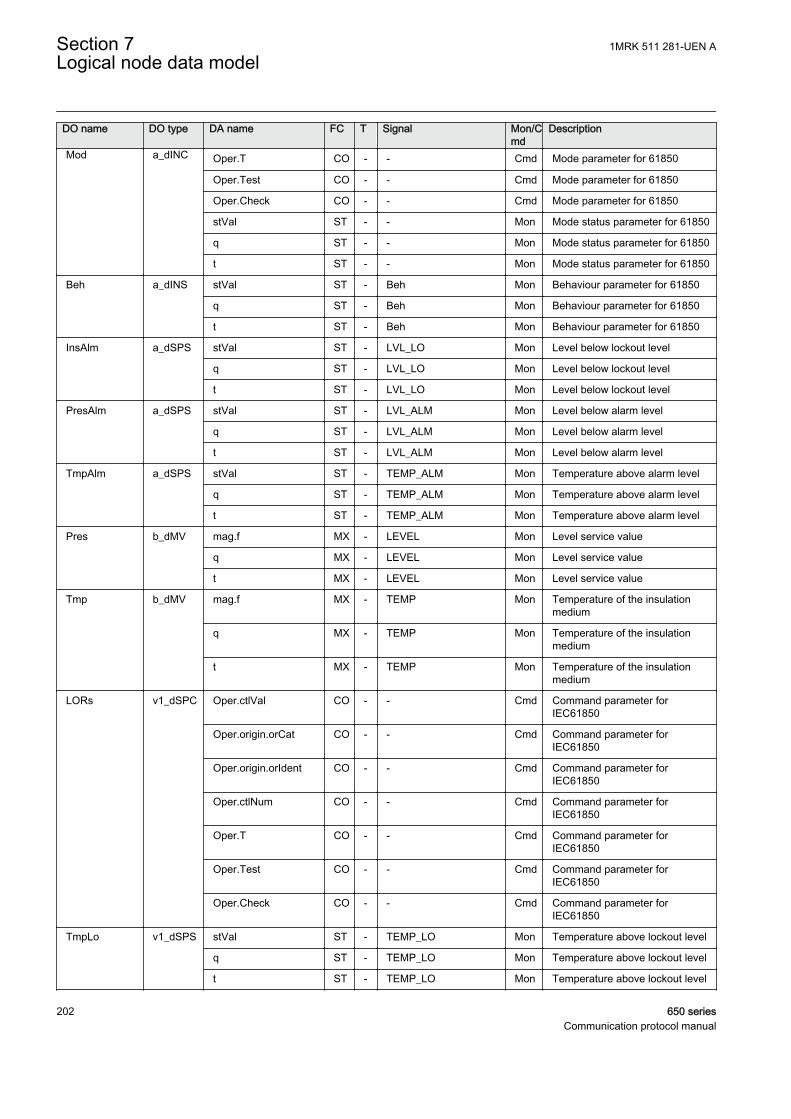
DO name DO type DA name FC T Signal Mon/Cmd
Description
Mod a_dINC Oper.T CO - - Cmd Mode parameter for 61850
Oper.Test CO - - Cmd Mode parameter for 61850
Oper.Check CO - - Cmd Mode parameter for 61850
stVal ST - - Mon Mode status parameter for 61850
q ST - - Mon Mode status parameter for 61850
t ST - - Mon Mode status parameter for 61850
Beh a_dINS stVal ST - Beh Mon Behaviour parameter for 61850
q ST - Beh Mon Behaviour parameter for 61850
t ST - Beh Mon Behaviour parameter for 61850
InsAlm a_dSPS stVal ST - LVL_LO Mon Level below lockout level
q ST - LVL_LO Mon Level below lockout level
t ST - LVL_LO Mon Level below lockout level
PresAlm a_dSPS stVal ST - LVL_ALM Mon Level below alarm level
q ST - LVL_ALM Mon Level below alarm level
t ST - LVL_ALM Mon Level below alarm level
TmpAlm a_dSPS stVal ST - TEMP_ALM Mon Temperature above alarm level
q ST - TEMP_ALM Mon Temperature above alarm level
t ST - TEMP_ALM Mon Temperature above alarm level
Pres b_dMV mag.f MX - LEVEL Mon Level service value
q MX - LEVEL Mon Level service value
t MX - LEVEL Mon Level service value
Tmp b_dMV mag.f MX - TEMP Mon Temperature of the insulationmedium
q MX - TEMP Mon Temperature of the insulationmedium
t MX - TEMP Mon Temperature of the insulationmedium
LORs v1_dSPC Oper.ctlVal CO - - Cmd Command parameter forIEC61850
Oper.origin.orCat CO - - Cmd Command parameter forIEC61850
Oper.origin.orIdent CO - - Cmd Command parameter forIEC61850
Oper.ctlNum CO - - Cmd Command parameter forIEC61850
Oper.T CO - - Cmd Command parameter forIEC61850
Oper.Test CO - - Cmd Command parameter forIEC61850
Oper.Check CO - - Cmd Command parameter forIEC61850
TmpLo v1_dSPS stVal ST - TEMP_LO Mon Temperature above lockout level
q ST - TEMP_LO Mon Temperature above lockout level
t ST - TEMP_LO Mon Temperature above lockout level
Section 7 1MRK 511 281-UEN ALogical node data model
202 650 seriesCommunication protocol manual
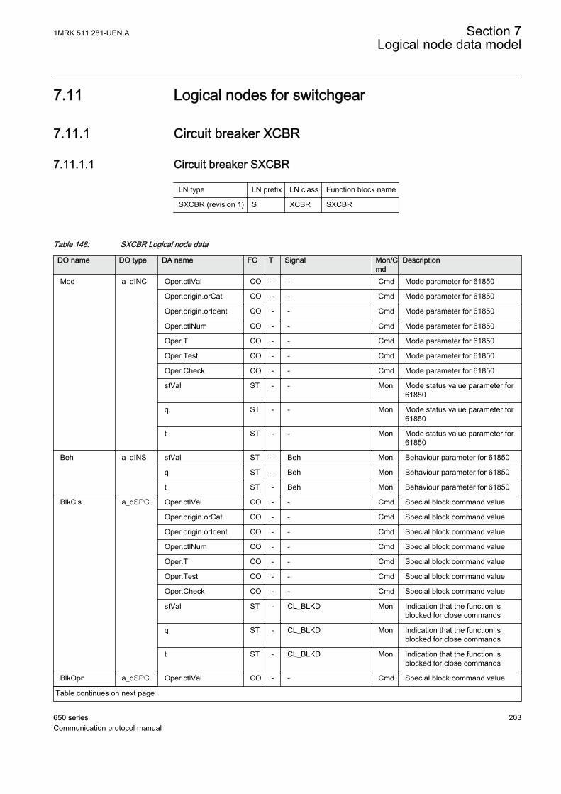
7.11 Logical nodes for switchgear
7.11.1 Circuit breaker XCBR
7.11.1.1 Circuit breaker SXCBR
LN type LN prefix LN class Function block name
SXCBR (revision 1) S XCBR SXCBR
Table 148: SXCBR Logical node data
DO name DO type DA name FC T Signal Mon/Cmd
Description
Mod a_dINC Oper.ctlVal CO - - Cmd Mode parameter for 61850
Oper.origin.orCat CO - - Cmd Mode parameter for 61850
Oper.origin.orIdent CO - - Cmd Mode parameter for 61850
Oper.ctlNum CO - - Cmd Mode parameter for 61850
Oper.T CO - - Cmd Mode parameter for 61850
Oper.Test CO - - Cmd Mode parameter for 61850
Oper.Check CO - - Cmd Mode parameter for 61850
stVal ST - - Mon Mode status value parameter for61850
q ST - - Mon Mode status value parameter for61850
t ST - - Mon Mode status value parameter for61850
Beh a_dINS stVal ST - Beh Mon Behaviour parameter for 61850
q ST - Beh Mon Behaviour parameter for 61850
t ST - Beh Mon Behaviour parameter for 61850
BlkCls a_dSPC Oper.ctlVal CO - - Cmd Special block command value
Oper.origin.orCat CO - - Cmd Special block command value
Oper.origin.orIdent CO - - Cmd Special block command value
Oper.ctlNum CO - - Cmd Special block command value
Oper.T CO - - Cmd Special block command value
Oper.Test CO - - Cmd Special block command value
Oper.Check CO - - Cmd Special block command value
stVal ST - CL_BLKD Mon Indication that the function isblocked for close commands
q ST - CL_BLKD Mon Indication that the function isblocked for close commands
t ST - CL_BLKD Mon Indication that the function isblocked for close commands
BlkOpn a_dSPC Oper.ctlVal CO - - Cmd Special block command value
Table continues on next page
1MRK 511 281-UEN A Section 7Logical node data model
650 series 203Communication protocol manual
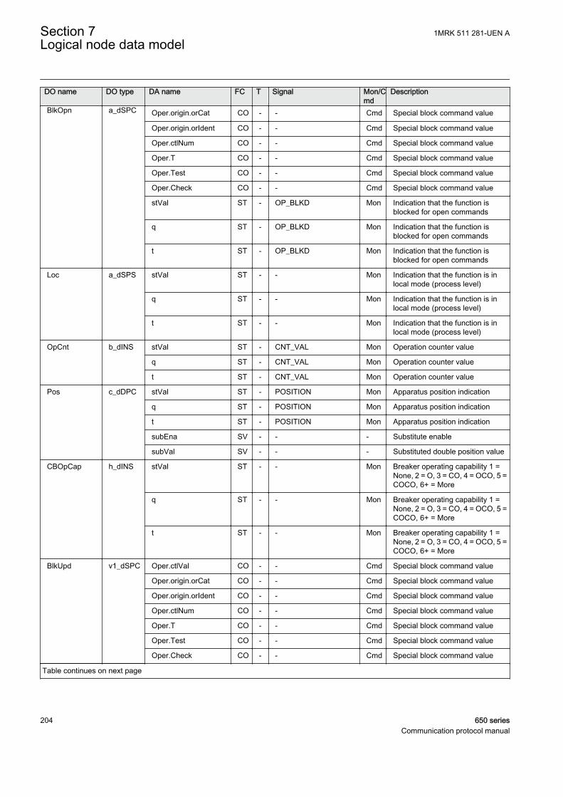
DO name DO type DA name FC T Signal Mon/Cmd
Description
BlkOpn a_dSPC Oper.origin.orCat CO - - Cmd Special block command value
Oper.origin.orIdent CO - - Cmd Special block command value
Oper.ctlNum CO - - Cmd Special block command value
Oper.T CO - - Cmd Special block command value
Oper.Test CO - - Cmd Special block command value
Oper.Check CO - - Cmd Special block command value
stVal ST - OP_BLKD Mon Indication that the function isblocked for open commands
q ST - OP_BLKD Mon Indication that the function isblocked for open commands
t ST - OP_BLKD Mon Indication that the function isblocked for open commands
Loc a_dSPS stVal ST - - Mon Indication that the function is inlocal mode (process level)
q ST - - Mon Indication that the function is inlocal mode (process level)
t ST - - Mon Indication that the function is inlocal mode (process level)
OpCnt b_dINS stVal ST - CNT_VAL Mon Operation counter value
q ST - CNT_VAL Mon Operation counter value
t ST - CNT_VAL Mon Operation counter value
Pos c_dDPC stVal ST - POSITION Mon Apparatus position indication
q ST - POSITION Mon Apparatus position indication
t ST - POSITION Mon Apparatus position indication
subEna SV - - - Substitute enable
subVal SV - - - Substituted double position value
CBOpCap h_dINS stVal ST - - Mon Breaker operating capability 1 =None, 2 = O, 3 = CO, 4 = OCO, 5 =COCO, 6+ = More
q ST - - Mon Breaker operating capability 1 =None, 2 = O, 3 = CO, 4 = OCO, 5 =COCO, 6+ = More
t ST - - Mon Breaker operating capability 1 =None, 2 = O, 3 = CO, 4 = OCO, 5 =COCO, 6+ = More
BlkUpd v1_dSPC Oper.ctlVal CO - - Cmd Special block command value
Oper.origin.orCat CO - - Cmd Special block command value
Oper.origin.orIdent CO - - Cmd Special block command value
Oper.ctlNum CO - - Cmd Special block command value
Oper.T CO - - Cmd Special block command value
Oper.Test CO - - Cmd Special block command value
Oper.Check CO - - Cmd Special block command value
Table continues on next page
Section 7 1MRK 511 281-UEN ALogical node data model
204 650 seriesCommunication protocol manual

DO name DO type DA name FC T Signal Mon/Cmd
Description
BlkUpd v1_dSPC stVal ST - UPD_BLKD Mon Update of position indication isblocked
q ST - UPD_BLKD Mon Update of position indication isblocked
t ST - UPD_BLKD Mon Update of position indication isblocked
7.11.2 Switch XSWI
7.11.2.1 Circuit switch SXSWI
LN type LN prefix LN class Function block name
SXSWI (revision 1) S XSWI SXSWI
Table 149: SXSWI Logical node data
DO name DO type DA name FC T Signal Mon/Cmd
Description
Mod a_dINC Oper.ctlVal CO - - Cmd Mode parameter for 61850
Oper.origin.orCat CO - - Cmd Mode parameter for 61850
Oper.origin.orIdent CO - - Cmd Mode parameter for 61850
Oper.ctlNum CO - - Cmd Mode parameter for 61850
Oper.T CO - - Cmd Mode parameter for 61850
Oper.Test CO - - Cmd Mode parameter for 61850
Oper.Check CO - - Cmd Mode parameter for 61850
stVal ST - - Mon Mode status value parameter for61850
q ST - - Mon Mode status value parameter for61850
t ST - - Mon Mode status value parameter for61850
Beh a_dINS stVal ST - Beh Mon Behaviour parameter for 61850
q ST - Beh Mon Behaviour parameter for 61850
t ST - Beh Mon Behaviour parameter for 61850
BlkCls a_dSPC Oper.ctlVal CO - - Cmd Special block command value
Oper.origin.orCat CO - - Cmd Special block command value
Oper.origin.orIdent CO - - Cmd Special block command value
Oper.ctlNum CO - - Cmd Special block command value
Oper.T CO - - Cmd Special block command value
Oper.Test CO - - Cmd Special block command value
Oper.Check CO - - Cmd Special block command value
Table continues on next page
1MRK 511 281-UEN A Section 7Logical node data model
650 series 205Communication protocol manual
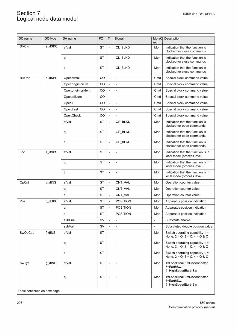
DO name DO type DA name FC T Signal Mon/Cmd
Description
BlkCls a_dSPC stVal ST - CL_BLKD Mon Indication that the function isblocked for close commands
q ST - CL_BLKD Mon Indication that the function isblocked for close commands
t ST - CL_BLKD Mon Indication that the function isblocked for close commands
BlkOpn a_dSPC Oper.ctlVal CO - - Cmd Special block command value
Oper.origin.orCat CO - - Cmd Special block command value
Oper.origin.orIdent CO - - Cmd Special block command value
Oper.ctlNum CO - - Cmd Special block command value
Oper.T CO - - Cmd Special block command value
Oper.Test CO - - Cmd Special block command value
Oper.Check CO - - Cmd Special block command value
stVal ST - OP_BLKD Mon Indication that the function isblocked for open commands
q ST - OP_BLKD Mon Indication that the function isblocked for open commands
t ST - OP_BLKD Mon Indication that the function isblocked for open commands
Loc a_dSPS stVal ST - - Mon Indication that the function is inlocal mode (process level)
q ST - - Mon Indication that the function is inlocal mode (process level)
t ST - - Mon Indication that the function is inlocal mode (process level)
OpCnt b_dINS stVal ST - CNT_VAL Mon Operation counter value
q ST - CNT_VAL Mon Operation counter value
t ST - CNT_VAL Mon Operation counter value
Pos c_dDPC stVal ST - POSITION Mon Apparatus position indication
q ST - POSITION Mon Apparatus position indication
t ST - POSITION Mon Apparatus position indication
subEna SV - - - Substitute enable
subVal SV - - - Substituted double position value
SwOpCap f_dINS stVal ST - - Mon Switch operating capability 1 =None, 2 = O, 3 = C, 4 = O & C
q ST - - Mon Switch operating capability 1 =None, 2 = O, 3 = C, 4 = O & C
t ST - - Mon Switch operating capability 1 =None, 2 = O, 3 = C, 4 = O & C
SwTyp g_dINS stVal ST - - Mon 1=LoadBreak,2=Disconnector,3=EarthSw,4=HighSpeedEarthSw
q ST - - Mon 1=LoadBreak,2=Disconnector,3=EarthSw,4=HighSpeedEarthSw
Table continues on next page
Section 7 1MRK 511 281-UEN ALogical node data model
206 650 seriesCommunication protocol manual
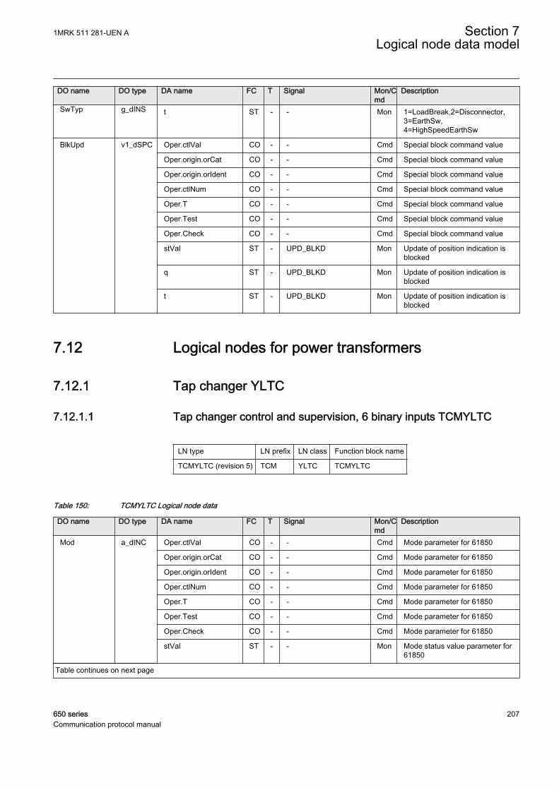
DO name DO type DA name FC T Signal Mon/Cmd
Description
SwTyp g_dINS t ST - - Mon 1=LoadBreak,2=Disconnector,3=EarthSw,4=HighSpeedEarthSw
BlkUpd v1_dSPC Oper.ctlVal CO - - Cmd Special block command value
Oper.origin.orCat CO - - Cmd Special block command value
Oper.origin.orIdent CO - - Cmd Special block command value
Oper.ctlNum CO - - Cmd Special block command value
Oper.T CO - - Cmd Special block command value
Oper.Test CO - - Cmd Special block command value
Oper.Check CO - - Cmd Special block command value
stVal ST - UPD_BLKD Mon Update of position indication isblocked
q ST - UPD_BLKD Mon Update of position indication isblocked
t ST - UPD_BLKD Mon Update of position indication isblocked
7.12 Logical nodes for power transformers
7.12.1 Tap changer YLTC
7.12.1.1 Tap changer control and supervision, 6 binary inputs TCMYLTC
LN type LN prefix LN class Function block name
TCMYLTC (revision 5) TCM YLTC TCMYLTC
Table 150: TCMYLTC Logical node data
DO name DO type DA name FC T Signal Mon/Cmd
Description
Mod a_dINC Oper.ctlVal CO - - Cmd Mode parameter for 61850
Oper.origin.orCat CO - - Cmd Mode parameter for 61850
Oper.origin.orIdent CO - - Cmd Mode parameter for 61850
Oper.ctlNum CO - - Cmd Mode parameter for 61850
Oper.T CO - - Cmd Mode parameter for 61850
Oper.Test CO - - Cmd Mode parameter for 61850
Oper.Check CO - - Cmd Mode parameter for 61850
stVal ST - - Mon Mode status value parameter for61850
Table continues on next page
1MRK 511 281-UEN A Section 7Logical node data model
650 series 207Communication protocol manual
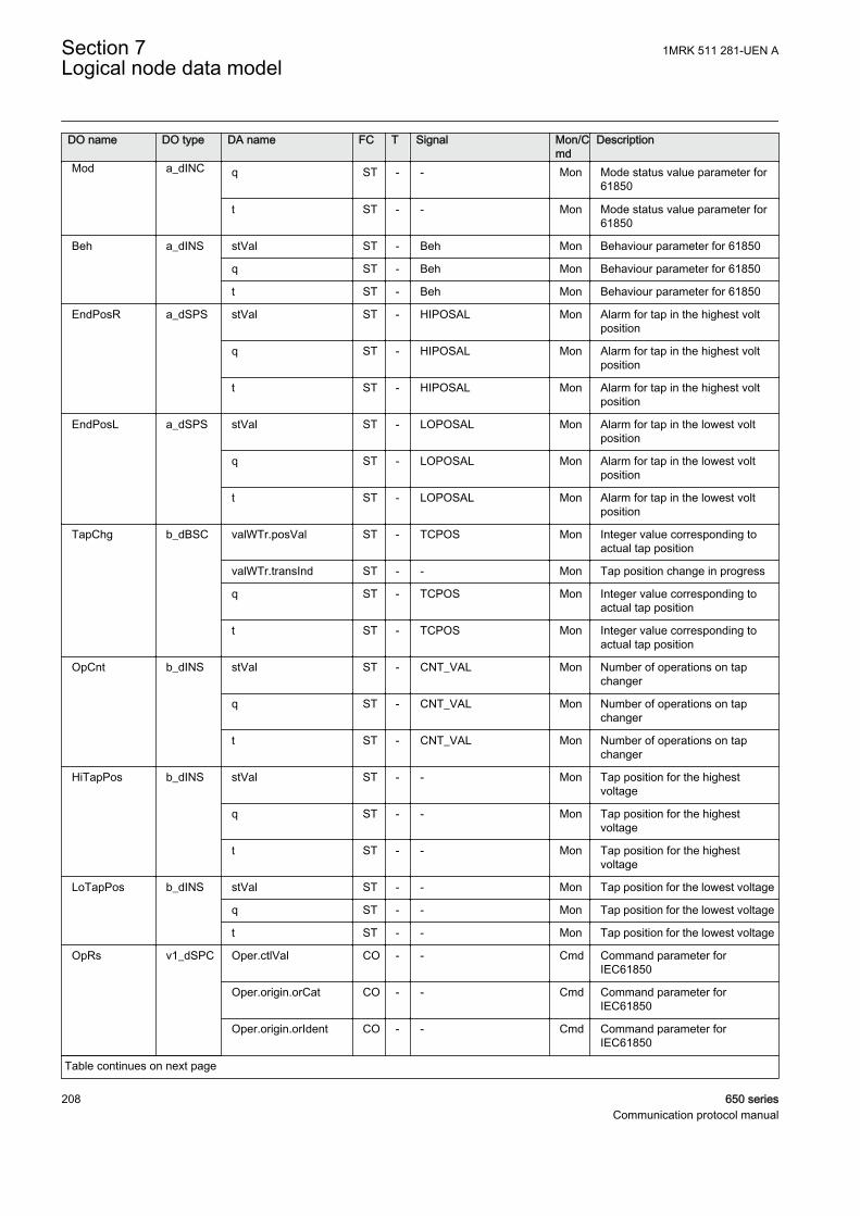
DO name DO type DA name FC T Signal Mon/Cmd
Description
Mod a_dINC q ST - - Mon Mode status value parameter for61850
t ST - - Mon Mode status value parameter for61850
Beh a_dINS stVal ST - Beh Mon Behaviour parameter for 61850
q ST - Beh Mon Behaviour parameter for 61850
t ST - Beh Mon Behaviour parameter for 61850
EndPosR a_dSPS stVal ST - HIPOSAL Mon Alarm for tap in the highest voltposition
q ST - HIPOSAL Mon Alarm for tap in the highest voltposition
t ST - HIPOSAL Mon Alarm for tap in the highest voltposition
EndPosL a_dSPS stVal ST - LOPOSAL Mon Alarm for tap in the lowest voltposition
q ST - LOPOSAL Mon Alarm for tap in the lowest voltposition
t ST - LOPOSAL Mon Alarm for tap in the lowest voltposition
TapChg b_dBSC valWTr.posVal ST - TCPOS Mon Integer value corresponding toactual tap position
valWTr.transInd ST - - Mon Tap position change in progress
q ST - TCPOS Mon Integer value corresponding toactual tap position
t ST - TCPOS Mon Integer value corresponding toactual tap position
OpCnt b_dINS stVal ST - CNT_VAL Mon Number of operations on tapchanger
q ST - CNT_VAL Mon Number of operations on tapchanger
t ST - CNT_VAL Mon Number of operations on tapchanger
HiTapPos b_dINS stVal ST - - Mon Tap position for the highestvoltage
q ST - - Mon Tap position for the highestvoltage
t ST - - Mon Tap position for the highestvoltage
LoTapPos b_dINS stVal ST - - Mon Tap position for the lowest voltage
q ST - - Mon Tap position for the lowest voltage
t ST - - Mon Tap position for the lowest voltage
OpRs v1_dSPC Oper.ctlVal CO - - Cmd Command parameter forIEC61850
Oper.origin.orCat CO - - Cmd Command parameter forIEC61850
Oper.origin.orIdent CO - - Cmd Command parameter forIEC61850
Table continues on next page
Section 7 1MRK 511 281-UEN ALogical node data model
208 650 seriesCommunication protocol manual
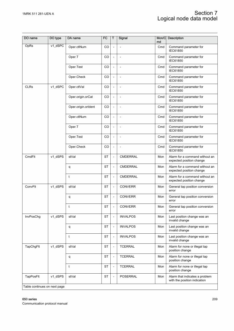
DO name DO type DA name FC T Signal Mon/Cmd
Description
OpRs v1_dSPC Oper.ctlNum CO - - Cmd Command parameter forIEC61850
Oper.T CO - - Cmd Command parameter forIEC61850
Oper.Test CO - - Cmd Command parameter forIEC61850
Oper.Check CO - - Cmd Command parameter forIEC61850
CLRs v1_dSPC Oper.ctlVal CO - - Cmd Command parameter forIEC61850
Oper.origin.orCat CO - - Cmd Command parameter forIEC61850
Oper.origin.orIdent CO - - Cmd Command parameter forIEC61850
Oper.ctlNum CO - - Cmd Command parameter forIEC61850
Oper.T CO - - Cmd Command parameter forIEC61850
Oper.Test CO - - Cmd Command parameter forIEC61850
Oper.Check CO - - Cmd Command parameter forIEC61850
CmdFlt v1_dSPS stVal ST - CMDERRAL Mon Alarm for a command without anexpected position change
q ST - CMDERRAL Mon Alarm for a command without anexpected position change
t ST - CMDERRAL Mon Alarm for a command without anexpected position change
ConvFlt v1_dSPS stVal ST - CONVERR Mon General tap position conversionerror
q ST - CONVERR Mon General tap position conversionerror
t ST - CONVERR Mon General tap position conversionerror
InvPosChg v1_dSPS stVal ST - INVALPOS Mon Last position change was aninvalid change
q ST - INVALPOS Mon Last position change was aninvalid change
t ST - INVALPOS Mon Last position change was aninvalid change
TapChgFlt v1_dSPS stVal ST - TCERRAL Mon Alarm for none or illegal tapposition change
q ST - TCERRAL Mon Alarm for none or illegal tapposition change
t ST - TCERRAL Mon Alarm for none or illegal tapposition change
TapPosFlt v1_dSPS stVal ST - POSERRAL Mon Alarm that indicates a problemwith the position indication
Table continues on next page
1MRK 511 281-UEN A Section 7Logical node data model
650 series 209Communication protocol manual
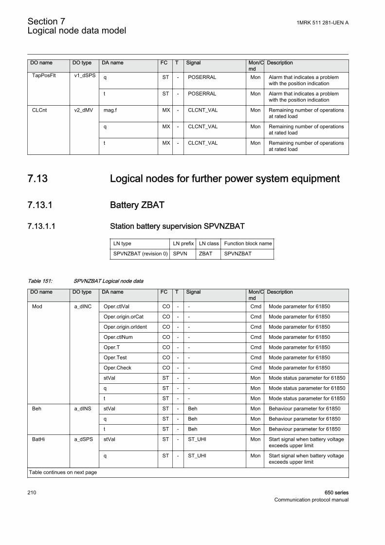
DO name DO type DA name FC T Signal Mon/Cmd
Description
TapPosFlt v1_dSPS q ST - POSERRAL Mon Alarm that indicates a problemwith the position indication
t ST - POSERRAL Mon Alarm that indicates a problemwith the position indication
CLCnt v2_dMV mag.f MX - CLCNT_VAL Mon Remaining number of operationsat rated load
q MX - CLCNT_VAL Mon Remaining number of operationsat rated load
t MX - CLCNT_VAL Mon Remaining number of operationsat rated load
7.13 Logical nodes for further power system equipment
7.13.1 Battery ZBAT
7.13.1.1 Station battery supervision SPVNZBAT
LN type LN prefix LN class Function block name
SPVNZBAT (revision 0) SPVN ZBAT SPVNZBAT
Table 151: SPVNZBAT Logical node data
DO name DO type DA name FC T Signal Mon/Cmd
Description
Mod a_dINC Oper.ctlVal CO - - Cmd Mode parameter for 61850
Oper.origin.orCat CO - - Cmd Mode parameter for 61850
Oper.origin.orIdent CO - - Cmd Mode parameter for 61850
Oper.ctlNum CO - - Cmd Mode parameter for 61850
Oper.T CO - - Cmd Mode parameter for 61850
Oper.Test CO - - Cmd Mode parameter for 61850
Oper.Check CO - - Cmd Mode parameter for 61850
stVal ST - - Mon Mode status parameter for 61850
q ST - - Mon Mode status parameter for 61850
t ST - - Mon Mode status parameter for 61850
Beh a_dINS stVal ST - Beh Mon Behaviour parameter for 61850
q ST - Beh Mon Behaviour parameter for 61850
t ST - Beh Mon Behaviour parameter for 61850
BatHi a_dSPS stVal ST - ST_UHI Mon Start signal when battery voltageexceeds upper limit
q ST - ST_UHI Mon Start signal when battery voltageexceeds upper limit
Table continues on next page
Section 7 1MRK 511 281-UEN ALogical node data model
210 650 seriesCommunication protocol manual

DO name DO type DA name FC T Signal Mon/Cmd
Description
BatHi a_dSPS t ST - ST_UHI Mon Start signal when battery voltageexceeds upper limit
BatLo a_dSPS stVal ST - ST_ULOW Mon Start signal when battery voltagedrops below lower limit
q ST - ST_ULOW Mon Start signal when battery voltagedrops below lower limit
t ST - ST_ULOW Mon Start signal when battery voltagedrops below lower limit
Vol b_dMV mag.f MX - BATTVOLT Mon Service value of the batteryterminal voltage
q MX - BATTVOLT Mon Service value of the batteryterminal voltage
t MX - BATTVOLT Mon Service value of the batteryterminal voltage
OpBatLo v1_dSPS stVal ST - AL_ULOW Mon Alarm when voltage has beenbelow low limit for a set time
q ST - AL_ULOW Mon Alarm when voltage has beenbelow low limit for a set time
t ST - AL_ULOW Mon Alarm when voltage has beenbelow low limit for a set time
OpBatHi v1_dSPS stVal ST - AL_UHI Mon Alarm when voltage has exceededhigh limit for a set time
q ST - AL_UHI Mon Alarm when voltage has exceededhigh limit for a set time
t ST - AL_UHI Mon Alarm when voltage has exceededhigh limit for a set time
1MRK 511 281-UEN A Section 7Logical node data model
650 series 211Communication protocol manual

212
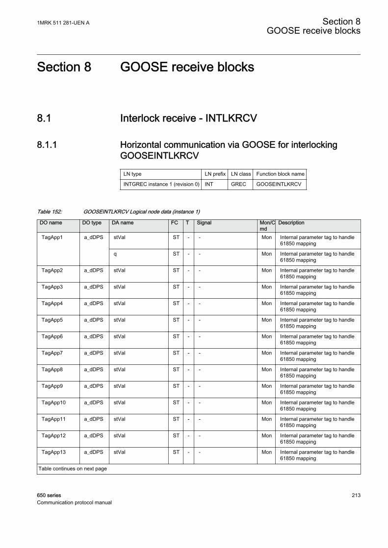
Section 8 GOOSE receive blocks
8.1 Interlock receive - INTLKRCV
8.1.1 Horizontal communication via GOOSE for interlockingGOOSEINTLKRCV
LN type LN prefix LN class Function block name
INTGREC instance 1 (revision 0) INT GREC GOOSEINTLKRCV
Table 152: GOOSEINTLKRCV Logical node data (instance 1)
DO name DO type DA name FC T Signal Mon/Cmd
Description
TagApp1 a_dDPS stVal ST - - Mon Internal parameter tag to handle61850 mapping
q ST - - Mon Internal parameter tag to handle61850 mapping
TagApp2 a_dDPS stVal ST - - Mon Internal parameter tag to handle61850 mapping
TagApp3 a_dDPS stVal ST - - Mon Internal parameter tag to handle61850 mapping
TagApp4 a_dDPS stVal ST - - Mon Internal parameter tag to handle61850 mapping
TagApp5 a_dDPS stVal ST - - Mon Internal parameter tag to handle61850 mapping
TagApp6 a_dDPS stVal ST - - Mon Internal parameter tag to handle61850 mapping
TagApp7 a_dDPS stVal ST - - Mon Internal parameter tag to handle61850 mapping
TagApp8 a_dDPS stVal ST - - Mon Internal parameter tag to handle61850 mapping
TagApp9 a_dDPS stVal ST - - Mon Internal parameter tag to handle61850 mapping
TagApp10 a_dDPS stVal ST - - Mon Internal parameter tag to handle61850 mapping
TagApp11 a_dDPS stVal ST - - Mon Internal parameter tag to handle61850 mapping
TagApp12 a_dDPS stVal ST - - Mon Internal parameter tag to handle61850 mapping
TagApp13 a_dDPS stVal ST - - Mon Internal parameter tag to handle61850 mapping
Table continues on next page
1MRK 511 281-UEN A Section 8GOOSE receive blocks
650 series 213Communication protocol manual
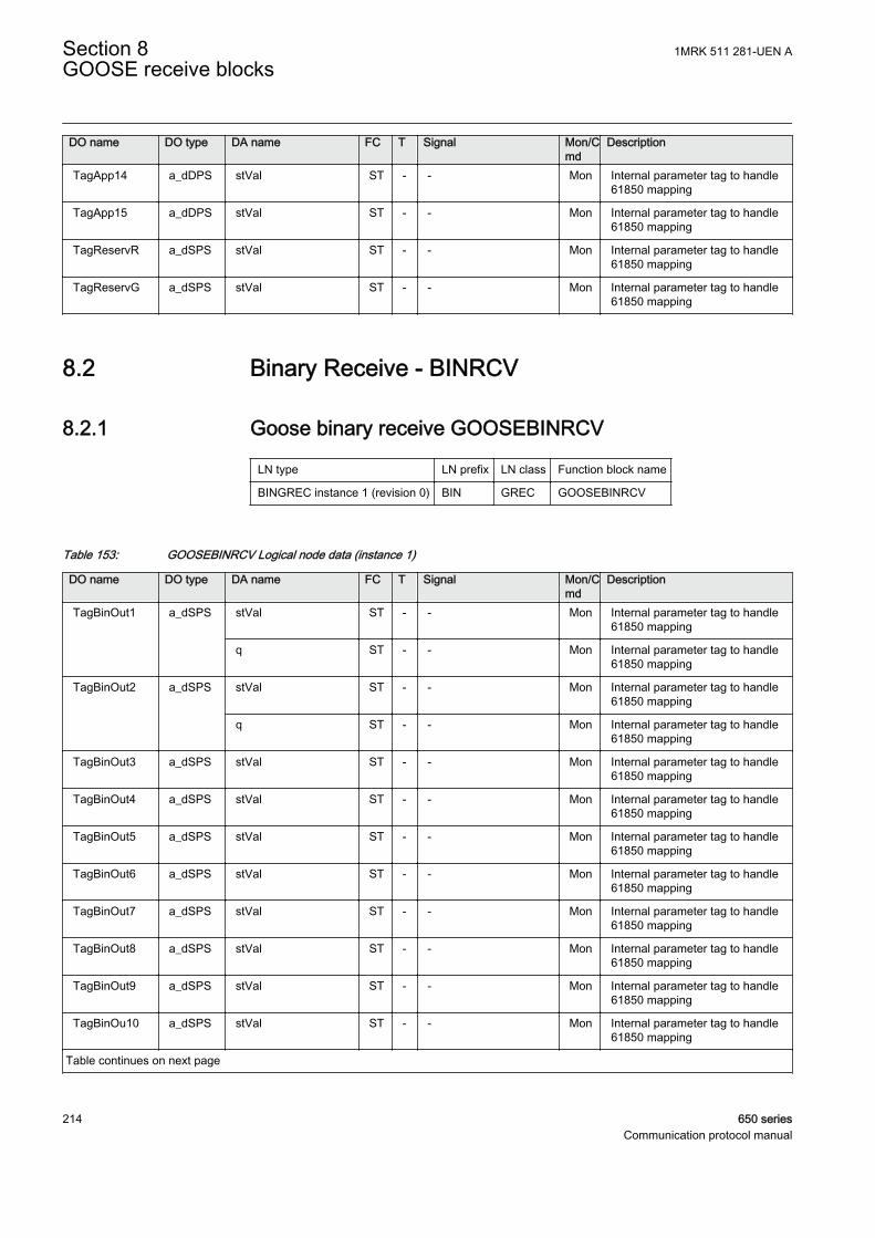
DO name DO type DA name FC T Signal Mon/Cmd
Description
TagApp14 a_dDPS stVal ST - - Mon Internal parameter tag to handle61850 mapping
TagApp15 a_dDPS stVal ST - - Mon Internal parameter tag to handle61850 mapping
TagReservR a_dSPS stVal ST - - Mon Internal parameter tag to handle61850 mapping
TagReservG a_dSPS stVal ST - - Mon Internal parameter tag to handle61850 mapping
8.2 Binary Receive - BINRCV
8.2.1 Goose binary receive GOOSEBINRCV
LN type LN prefix LN class Function block name
BINGREC instance 1 (revision 0) BIN GREC GOOSEBINRCV
Table 153: GOOSEBINRCV Logical node data (instance 1)
DO name DO type DA name FC T Signal Mon/Cmd
Description
TagBinOut1 a_dSPS stVal ST - - Mon Internal parameter tag to handle61850 mapping
q ST - - Mon Internal parameter tag to handle61850 mapping
TagBinOut2 a_dSPS stVal ST - - Mon Internal parameter tag to handle61850 mapping
q ST - - Mon Internal parameter tag to handle61850 mapping
TagBinOut3 a_dSPS stVal ST - - Mon Internal parameter tag to handle61850 mapping
TagBinOut4 a_dSPS stVal ST - - Mon Internal parameter tag to handle61850 mapping
TagBinOut5 a_dSPS stVal ST - - Mon Internal parameter tag to handle61850 mapping
TagBinOut6 a_dSPS stVal ST - - Mon Internal parameter tag to handle61850 mapping
TagBinOut7 a_dSPS stVal ST - - Mon Internal parameter tag to handle61850 mapping
TagBinOut8 a_dSPS stVal ST - - Mon Internal parameter tag to handle61850 mapping
TagBinOut9 a_dSPS stVal ST - - Mon Internal parameter tag to handle61850 mapping
TagBinOu10 a_dSPS stVal ST - - Mon Internal parameter tag to handle61850 mapping
Table continues on next page
Section 8 1MRK 511 281-UEN AGOOSE receive blocks
214 650 seriesCommunication protocol manual
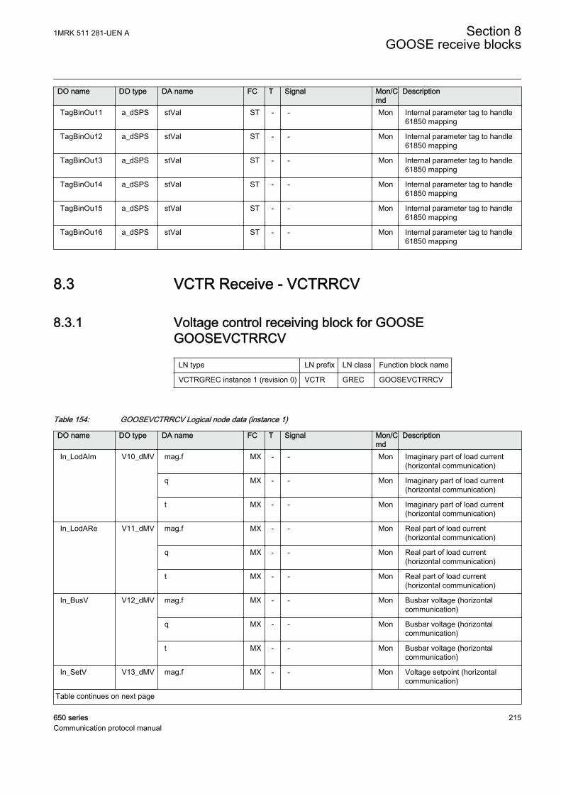
DO name DO type DA name FC T Signal Mon/Cmd
Description
TagBinOu11 a_dSPS stVal ST - - Mon Internal parameter tag to handle61850 mapping
TagBinOu12 a_dSPS stVal ST - - Mon Internal parameter tag to handle61850 mapping
TagBinOu13 a_dSPS stVal ST - - Mon Internal parameter tag to handle61850 mapping
TagBinOu14 a_dSPS stVal ST - - Mon Internal parameter tag to handle61850 mapping
TagBinOu15 a_dSPS stVal ST - - Mon Internal parameter tag to handle61850 mapping
TagBinOu16 a_dSPS stVal ST - - Mon Internal parameter tag to handle61850 mapping
8.3 VCTR Receive - VCTRRCV
8.3.1 Voltage control receiving block for GOOSEGOOSEVCTRRCV
LN type LN prefix LN class Function block name
VCTRGREC instance 1 (revision 0) VCTR GREC GOOSEVCTRRCV
Table 154: GOOSEVCTRRCV Logical node data (instance 1)
DO name DO type DA name FC T Signal Mon/Cmd
Description
In_LodAIm V10_dMV mag.f MX - - Mon Imaginary part of load current(horizontal communication)
q MX - - Mon Imaginary part of load current(horizontal communication)
t MX - - Mon Imaginary part of load current(horizontal communication)
In_LodARe V11_dMV mag.f MX - - Mon Real part of load current(horizontal communication)
q MX - - Mon Real part of load current(horizontal communication)
t MX - - Mon Real part of load current(horizontal communication)
In_BusV V12_dMV mag.f MX - - Mon Busbar voltage (horizontalcommunication)
q MX - - Mon Busbar voltage (horizontalcommunication)
t MX - - Mon Busbar voltage (horizontalcommunication)
In_SetV V13_dMV mag.f MX - - Mon Voltage setpoint (horizontalcommunication)
Table continues on next page
1MRK 511 281-UEN A Section 8GOOSE receive blocks
650 series 215Communication protocol manual
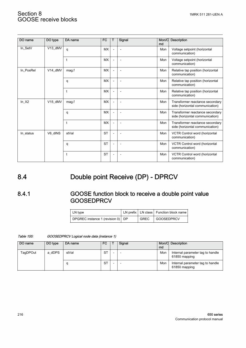
DO name DO type DA name FC T Signal Mon/Cmd
Description
In_SetV V13_dMV q MX - - Mon Voltage setpoint (horizontalcommunication)
t MX - - Mon Voltage setpoint (horizontalcommunication)
In_PosRel V14_dMV mag.f MX - - Mon Relative tap position (horizontalcommunication)
q MX - - Mon Relative tap position (horizontalcommunication)
t MX - - Mon Relative tap position (horizontalcommunication)
In_X2 V15_dMV mag.f MX - - Mon Transformer reactance secondaryside (horizontal communication)
q MX - - Mon Transformer reactance secondaryside (horizontal communication)
t MX - - Mon Transformer reactance secondaryside (horizontal communication)
In_status V6_dINS stVal ST - - Mon VCTR Control word (horizontalcommunication)
q ST - - Mon VCTR Control word (horizontalcommunication)
t ST - - Mon VCTR Control word (horizontalcommunication)
8.4 Double point Receive (DP) - DPRCV
8.4.1 GOOSE function block to receive a double point valueGOOSEDPRCV
LN type LN prefix LN class Function block name
DPGREC instance 1 (revision 0) DP GREC GOOSEDPRCV
Table 155: GOOSEDPRCV Logical node data (instance 1)
DO name DO type DA name FC T Signal Mon/Cmd
Description
TagDPOut a_dDPS stVal ST - - Mon Internal parameter tag to handle61850 mapping
q ST - - Mon Internal parameter tag to handle61850 mapping
Section 8 1MRK 511 281-UEN AGOOSE receive blocks
216 650 seriesCommunication protocol manual
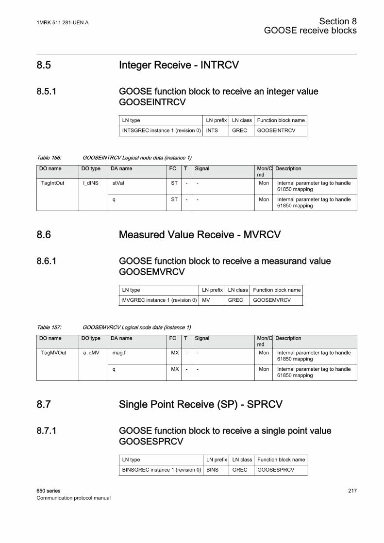
8.5 Integer Receive - INTRCV
8.5.1 GOOSE function block to receive an integer valueGOOSEINTRCV
LN type LN prefix LN class Function block name
INTSGREC instance 1 (revision 0) INTS GREC GOOSEINTRCV
Table 156: GOOSEINTRCV Logical node data (instance 1)
DO name DO type DA name FC T Signal Mon/Cmd
Description
TagIntOut l_dINS stVal ST - - Mon Internal parameter tag to handle61850 mapping
q ST - - Mon Internal parameter tag to handle61850 mapping
8.6 Measured Value Receive - MVRCV
8.6.1 GOOSE function block to receive a measurand valueGOOSEMVRCV
LN type LN prefix LN class Function block name
MVGREC instance 1 (revision 0) MV GREC GOOSEMVRCV
Table 157: GOOSEMVRCV Logical node data (instance 1)
DO name DO type DA name FC T Signal Mon/Cmd
Description
TagMVOut a_dMV mag.f MX - - Mon Internal parameter tag to handle61850 mapping
q MX - - Mon Internal parameter tag to handle61850 mapping
8.7 Single Point Receive (SP) - SPRCV
8.7.1 GOOSE function block to receive a single point valueGOOSESPRCV
LN type LN prefix LN class Function block name
BINSGREC instance 1 (revision 0) BINS GREC GOOSESPRCV
1MRK 511 281-UEN A Section 8GOOSE receive blocks
650 series 217Communication protocol manual

Table 158: GOOSESPRCV Logical node data (instance 1)
DO name DO type DA name FC T Signal Mon/Cmd
Description
TagBinOut a_dSPS stVal ST - - Mon Internal parameter tag to handle61850 mapping
q ST - - Mon Internal parameter tag to handle61850 mapping
Section 8 1MRK 511 281-UEN AGOOSE receive blocks
218 650 seriesCommunication protocol manual
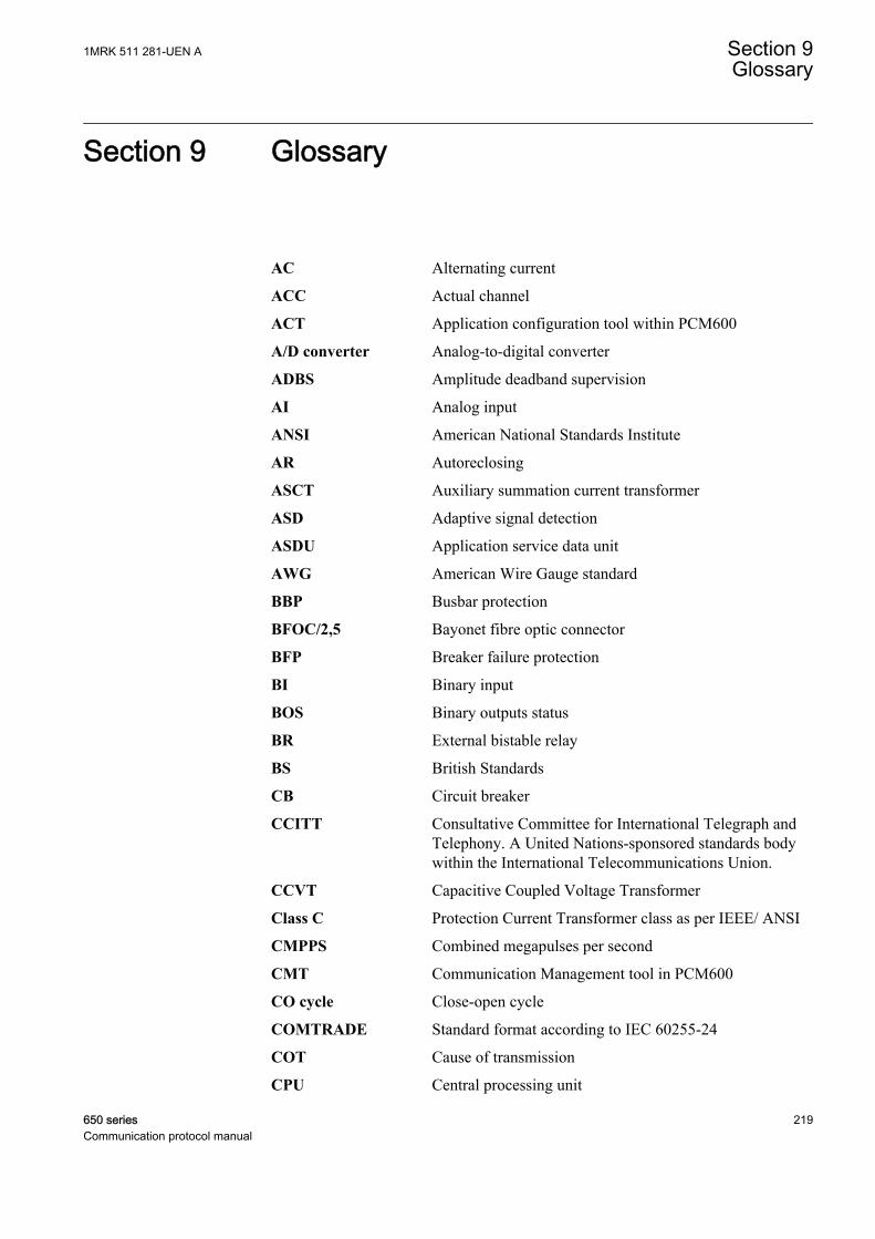
Section 9 Glossary
AC Alternating current
ACC Actual channel
ACT Application configuration tool within PCM600
A/D converter Analog-to-digital converter
ADBS Amplitude deadband supervision
AI Analog input
ANSI American National Standards Institute
AR Autoreclosing
ASCT Auxiliary summation current transformer
ASD Adaptive signal detection
ASDU Application service data unit
AWG American Wire Gauge standard
BBP Busbar protection
BFOC/2,5 Bayonet fibre optic connector
BFP Breaker failure protection
BI Binary input
BOS Binary outputs status
BR External bistable relay
BS British Standards
CB Circuit breaker
CCITT Consultative Committee for International Telegraph andTelephony. A United Nations-sponsored standards bodywithin the International Telecommunications Union.
CCVT Capacitive Coupled Voltage Transformer
Class C Protection Current Transformer class as per IEEE/ ANSI
CMPPS Combined megapulses per second
CMT Communication Management tool in PCM600
CO cycle Close-open cycle
COMTRADE Standard format according to IEC 60255-24
COT Cause of transmission
CPU Central processing unit
1MRK 511 281-UEN A Section 9Glossary
650 series 219Communication protocol manual

CR Carrier receive
CRC Cyclic redundancy check
CROB Control relay output block
CS Carrier send
CT Current transformer
CU Communication unit
CVT Capacitive voltage transformer
DAR Delayed autoreclosing
DARPA Defense Advanced Research Projects Agency (The USdeveloper of the TCP/IP protocol etc.)
DBDL Dead bus dead line
DBLL Dead bus live line
DC Direct current
DFC Data flow control
DFT Discrete Fourier transform
DHCP Dynamic Host Configuration Protocol
DI Digital input
DLLB Dead line live bus
DNP Distributed Network Protocol as per IEEE Std 1815-2012
DR Disturbance recorder
DRAM Dynamic random access memory
DRH Disturbance report handler
DTT Direct transfer trip scheme
EHV network Extra high voltage network
EIA Electronic Industries Association
EMC Electromagnetic compatibility
EMF Electromotive force
EMI Electromagnetic interference
EnFP End fault protection
EPA Enhanced performance architecture
ESD Electrostatic discharge
F-SMA Type of optical fibre connector
FAN Fault number
FCB Flow control bit; Frame count bit
Section 9 1MRK 511 281-UEN AGlossary
220 650 seriesCommunication protocol manual
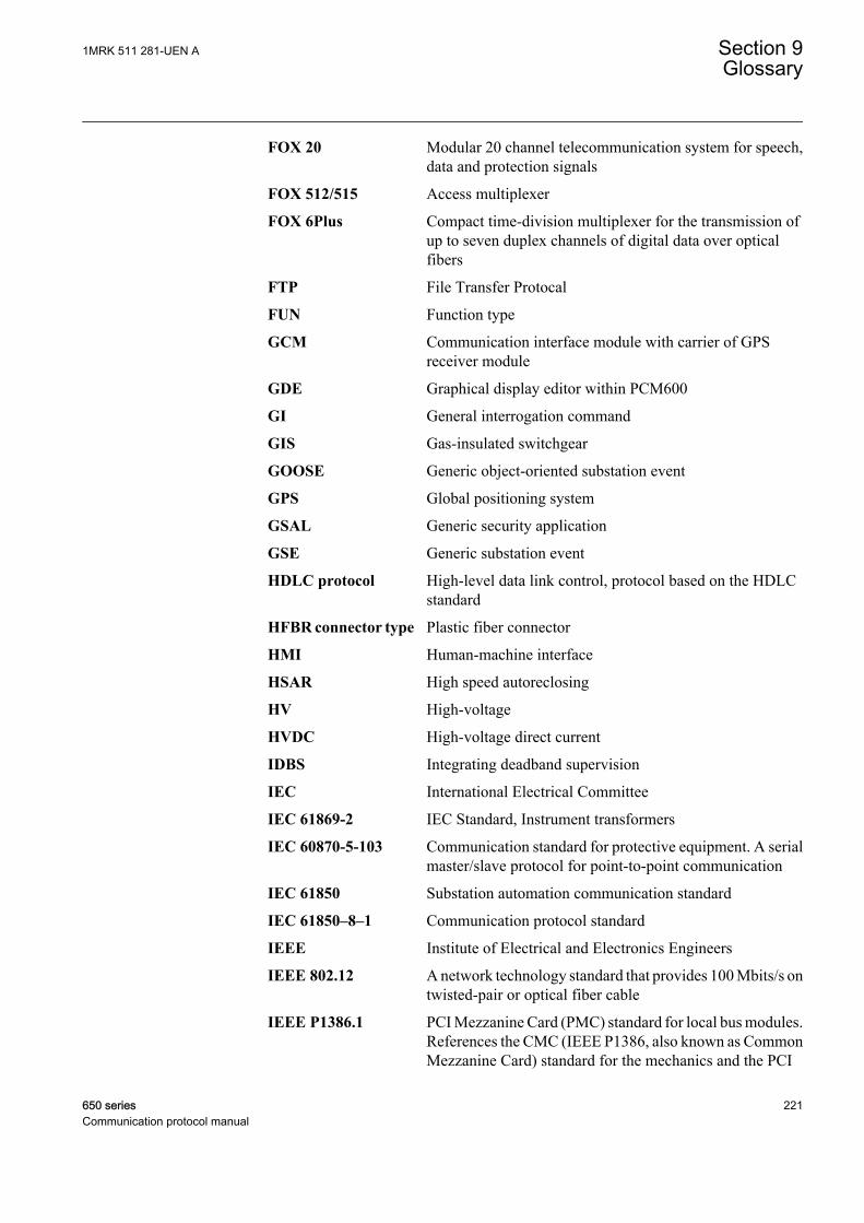
FOX 20 Modular 20 channel telecommunication system for speech,data and protection signals
FOX 512/515 Access multiplexer
FOX 6Plus Compact time-division multiplexer for the transmission ofup to seven duplex channels of digital data over opticalfibers
FTP File Transfer Protocal
FUN Function type
GCM Communication interface module with carrier of GPSreceiver module
GDE Graphical display editor within PCM600
GI General interrogation command
GIS Gas-insulated switchgear
GOOSE Generic object-oriented substation event
GPS Global positioning system
GSAL Generic security application
GSE Generic substation event
HDLC protocol High-level data link control, protocol based on the HDLCstandard
HFBR connector type Plastic fiber connector
HMI Human-machine interface
HSAR High speed autoreclosing
HV High-voltage
HVDC High-voltage direct current
IDBS Integrating deadband supervision
IEC International Electrical Committee
IEC 61869-2 IEC Standard, Instrument transformers
IEC 60870-5-103 Communication standard for protective equipment. A serialmaster/slave protocol for point-to-point communication
IEC 61850 Substation automation communication standard
IEC 61850–8–1 Communication protocol standard
IEEE Institute of Electrical and Electronics Engineers
IEEE 802.12 A network technology standard that provides 100 Mbits/s ontwisted-pair or optical fiber cable
IEEE P1386.1 PCI Mezzanine Card (PMC) standard for local bus modules.References the CMC (IEEE P1386, also known as CommonMezzanine Card) standard for the mechanics and the PCI
1MRK 511 281-UEN A Section 9Glossary
650 series 221Communication protocol manual
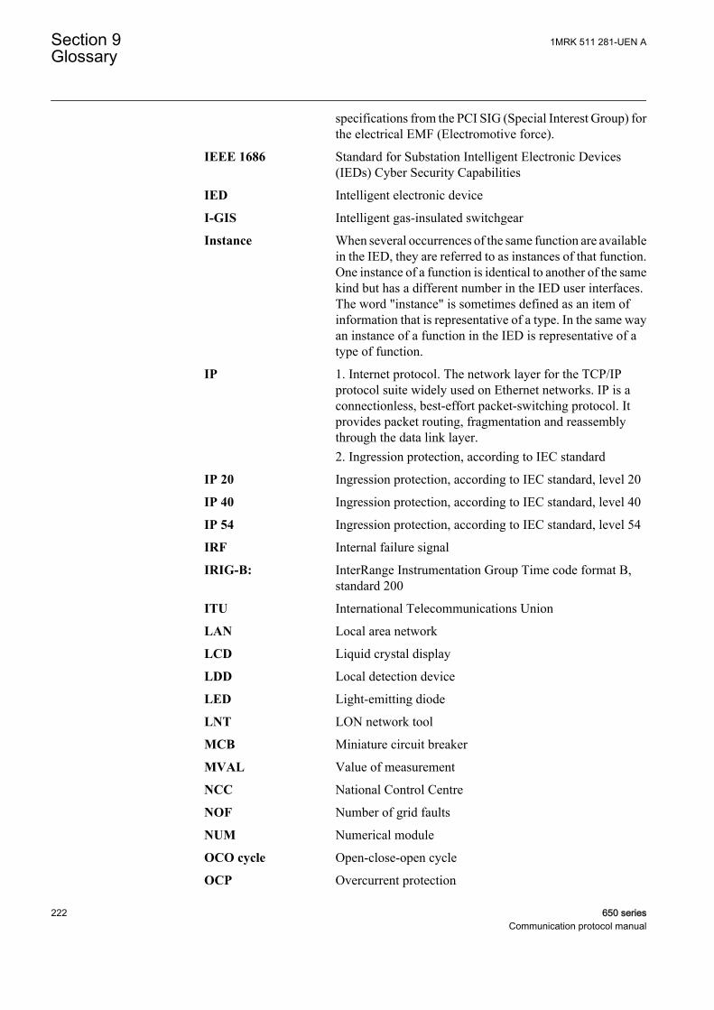
specifications from the PCI SIG (Special Interest Group) forthe electrical EMF (Electromotive force).
IEEE 1686 Standard for Substation Intelligent Electronic Devices(IEDs) Cyber Security Capabilities
IED Intelligent electronic device
I-GIS Intelligent gas-insulated switchgear
Instance When several occurrences of the same function are availablein the IED, they are referred to as instances of that function.One instance of a function is identical to another of the samekind but has a different number in the IED user interfaces.The word "instance" is sometimes defined as an item ofinformation that is representative of a type. In the same wayan instance of a function in the IED is representative of atype of function.
IP 1. Internet protocol. The network layer for the TCP/IPprotocol suite widely used on Ethernet networks. IP is aconnectionless, best-effort packet-switching protocol. Itprovides packet routing, fragmentation and reassemblythrough the data link layer.2. Ingression protection, according to IEC standard
IP 20 Ingression protection, according to IEC standard, level 20
IP 40 Ingression protection, according to IEC standard, level 40
IP 54 Ingression protection, according to IEC standard, level 54
IRF Internal failure signal
IRIG-B: InterRange Instrumentation Group Time code format B,standard 200
ITU International Telecommunications Union
LAN Local area network
LCD Liquid crystal display
LDD Local detection device
LED Light-emitting diode
LNT LON network tool
MCB Miniature circuit breaker
MVAL Value of measurement
NCC National Control Centre
NOF Number of grid faults
NUM Numerical module
OCO cycle Open-close-open cycle
OCP Overcurrent protection
Section 9 1MRK 511 281-UEN AGlossary
222 650 seriesCommunication protocol manual
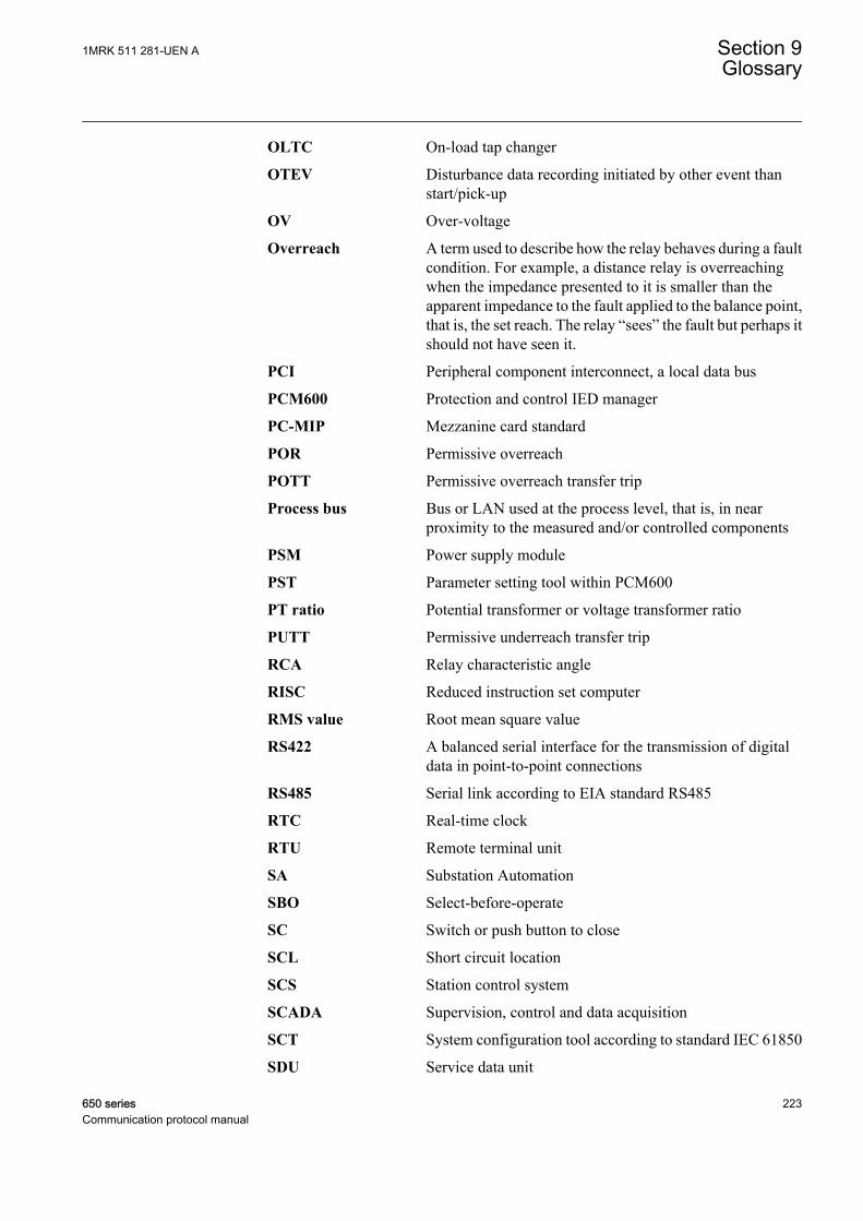
OLTC On-load tap changer
OTEV Disturbance data recording initiated by other event thanstart/pick-up
OV Over-voltage
Overreach A term used to describe how the relay behaves during a faultcondition. For example, a distance relay is overreachingwhen the impedance presented to it is smaller than theapparent impedance to the fault applied to the balance point,that is, the set reach. The relay “sees” the fault but perhaps itshould not have seen it.
PCI Peripheral component interconnect, a local data bus
PCM600 Protection and control IED manager
PC-MIP Mezzanine card standard
POR Permissive overreach
POTT Permissive overreach transfer trip
Process bus Bus or LAN used at the process level, that is, in nearproximity to the measured and/or controlled components
PSM Power supply module
PST Parameter setting tool within PCM600
PT ratio Potential transformer or voltage transformer ratio
PUTT Permissive underreach transfer trip
RCA Relay characteristic angle
RISC Reduced instruction set computer
RMS value Root mean square value
RS422 A balanced serial interface for the transmission of digitaldata in point-to-point connections
RS485 Serial link according to EIA standard RS485
RTC Real-time clock
RTU Remote terminal unit
SA Substation Automation
SBO Select-before-operate
SC Switch or push button to close
SCL Short circuit location
SCS Station control system
SCADA Supervision, control and data acquisition
SCT System configuration tool according to standard IEC 61850
SDU Service data unit
1MRK 511 281-UEN A Section 9Glossary
650 series 223Communication protocol manual
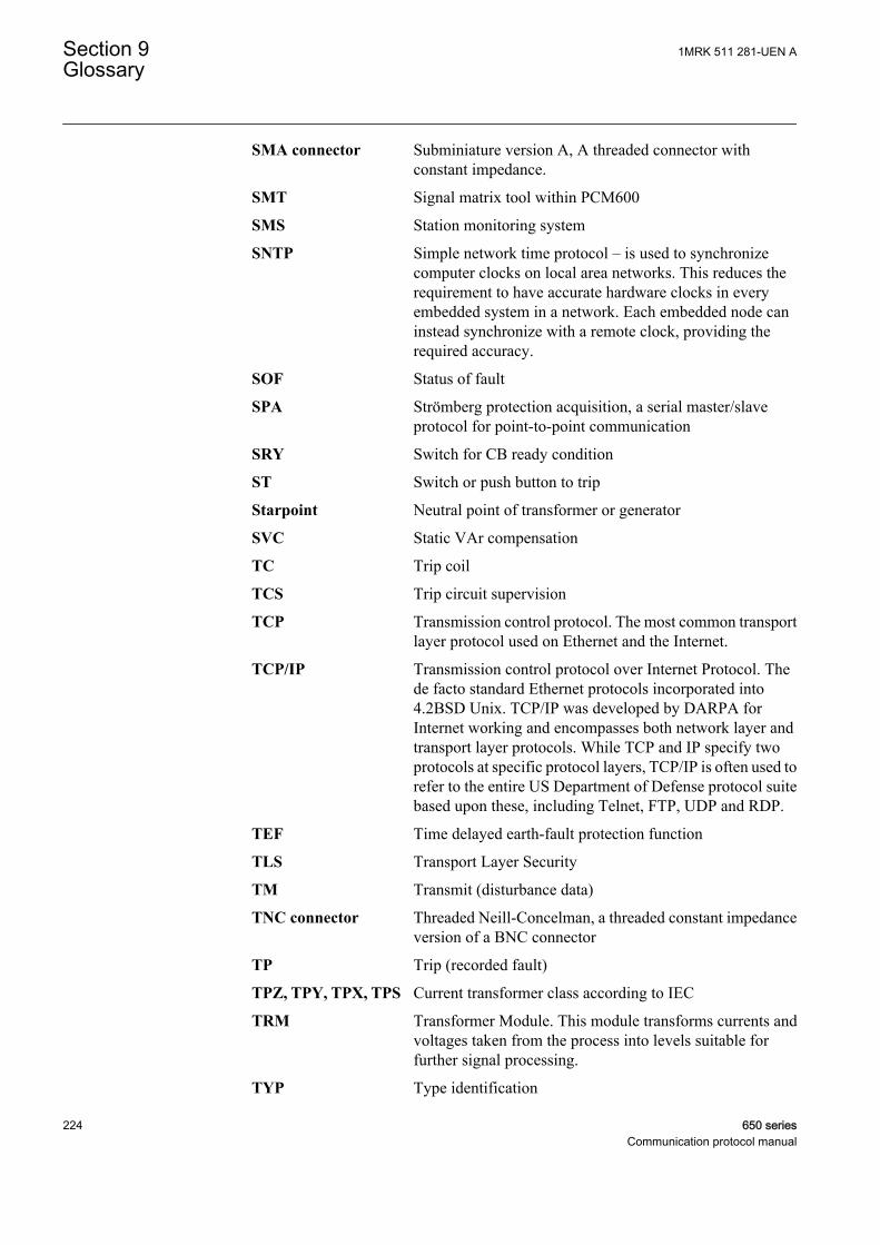
SMA connector Subminiature version A, A threaded connector withconstant impedance.
SMT Signal matrix tool within PCM600
SMS Station monitoring system
SNTP Simple network time protocol – is used to synchronizecomputer clocks on local area networks. This reduces therequirement to have accurate hardware clocks in everyembedded system in a network. Each embedded node caninstead synchronize with a remote clock, providing therequired accuracy.
SOF Status of fault
SPA Strömberg protection acquisition, a serial master/slaveprotocol for point-to-point communication
SRY Switch for CB ready condition
ST Switch or push button to trip
Starpoint Neutral point of transformer or generator
SVC Static VAr compensation
TC Trip coil
TCS Trip circuit supervision
TCP Transmission control protocol. The most common transportlayer protocol used on Ethernet and the Internet.
TCP/IP Transmission control protocol over Internet Protocol. Thede facto standard Ethernet protocols incorporated into4.2BSD Unix. TCP/IP was developed by DARPA forInternet working and encompasses both network layer andtransport layer protocols. While TCP and IP specify twoprotocols at specific protocol layers, TCP/IP is often used torefer to the entire US Department of Defense protocol suitebased upon these, including Telnet, FTP, UDP and RDP.
TEF Time delayed earth-fault protection function
TLS Transport Layer Security
TM Transmit (disturbance data)
TNC connector Threaded Neill-Concelman, a threaded constant impedanceversion of a BNC connector
TP Trip (recorded fault)
TPZ, TPY, TPX, TPS Current transformer class according to IEC
TRM Transformer Module. This module transforms currents andvoltages taken from the process into levels suitable forfurther signal processing.
TYP Type identification
Section 9 1MRK 511 281-UEN AGlossary
224 650 seriesCommunication protocol manual
UMT User management tool
Underreach A term used to describe how the relay behaves during a faultcondition. For example, a distance relay is underreachingwhen the impedance presented to it is greater than theapparent impedance to the fault applied to the balance point,that is, the set reach. The relay does not “see” the fault butperhaps it should have seen it. See also Overreach.
UTC Coordinated Universal Time. A coordinated time scale,maintained by the Bureau International des Poids et Mesures(BIPM), which forms the basis of a coordinateddissemination of standard frequencies and time signals.UTC is derived from International Atomic Time (TAI) bythe addition of a whole number of "leap seconds" tosynchronize it with Universal Time 1 (UT1), thus allowingfor the eccentricity of the Earth's orbit, the rotational axis tilt(23.5 degrees), but still showing the Earth's irregularrotation, on which UT1 is based. The Coordinated UniversalTime is expressed using a 24-hour clock, and uses theGregorian calendar. It is used for aeroplane and shipnavigation, where it is also sometimes known by the militaryname, "Zulu time." "Zulu" in the phonetic alphabet standsfor "Z", which stands for longitude zero.
UV Undervoltage
WEI Weak end infeed logic
VT Voltage transformer
3IO Three times zero-sequence current. Often referred to as theresidual or the earth-fault current
3UO Three times the zero sequence voltage. Often referred to asthe residual voltage or the neutral point voltage
1MRK 511 281-UEN A Section 9Glossary
650 series 225Communication protocol manual

226

227
Contact us
For more information please contact:
ABB ABGrid Automation ProductsSE-721 59 Västerås, SwedenPhone +46 (0) 21 32 50 00
www.abb.com/protection-control
Note:We reserve the right to make technical changes or modifythe contents of this document without prior notice. ABB ABdoes not accept any responsibility whatsoever for potentialerrors or possible lack of information in this document.We reserve all rights in this document and in the subjectmatter and illustrations contained herein. Any reproduction,disclosure to third parties or utilization of its contents – inwhole or in part – is forbidden without prior written consent ofABB AB.
© Copyright 2013 ABB.
All rights reserved.
Scan this QR code to visit our website
1MR
K 5
11 2
81-U
EN