complete newsletter in pdf
TRANSCRIPT

Reeo"'oRlool

Government of India
BHABHA ATOMIC RESEARCH CENTRE
BARC Founders Day Special Issue
October 2002 Issue No. 225

I
DEDICATED TO THEMEMORY OF
Homi Jehangir Bhabha(1906- 1966)
Founder and Architect ofIndian Atomic Energy Programme

EJli~rial Staff
CHIEF EDITORDc Vij" Kom"
MANAGING EDITDRT.c.."00
Compute, G.-phles, Design" LayoutFAS. W'rnec
Newsletter on the Web
Available atURL,http//www.ban;.emet.in
"When nuclear energy hasbeen successfully appliedto powe, production in,say, a couple of decadesfrom now, India will nothave to look abroad for itsexperts, but willfind them ready at hand..
- Homl Bhabha
October 2002
BARC N EWSLETrER
An ideal thyratron-less repetitive TE- laser pulser 1Dhruba .1yotl BiswasHomi Bhabha Science & Technology Award for the year 2000
Design and development of drive mechanisms foradjuster rods, control rods and shut-off rods ofTarapur Atomic Power Projects -3&.4 ,12Manjit Singh et al.BARC Technical Excellence Award for the year 2000
Folded tandem ion accelerator facility at BARC ,22Pitamber SinghBARC Technical Excellence Award for the year 2000
Ultrafast dynamics of charge and electron transferreactions in condensed media 33Dipak K, Pallt"Bronze Medal of 2001" by the Chemical Research Society of Indiain its Annual Conference held at Pune
Preparation, optimization/characterization and ion-exchange behaviour of V(II) formulations .., 42.1,Manianna and G. VenkateswaranBest Paper award presented under Analytical and EnvironmentalSection (AP-23) at XIX Annual Conference of Indian CouncilofChemists, held at Kuvempu University, Shimoga (Kamataka)in December 2000, and 'Young Scientist Award' for Dr J. Manjanna
Transport of metal ions across a supported liquidmembrane (SLM) using dimethyl dibutyl tetradecyl-l,3-malonamide (DMDBTDMA) as the carrier 50S. Sriram and V.K. HanchandaBest Paper award at NUCAR-2001 held at University of Pune, Pune
Remotely operated non-destructive surface samplingtechniques'for assessment of residual service life 53Kundan Kumar and B,B. RupaniBest Paperaward at the seminar on "Roleof NDEin Residual LifeAssessment &Plant Life Extension" held at Lonavala in December 2001

Simulation of pressurised heavy water reactordata using artificial neural network for reactorstatus/transient identification 57P.V. Yarde et a/.Best Paperaward in the technical sessions of InternationalConference on Quality, Reliability and Control (ICQRC-2001)held at Mumballn December 2001
Removal of Ru along with Cs & Sr from the lowlevel radioactive liquid waste of reprocessingplant by chemical treatment method 64S.G. Kore et a/.Best Paper award In the Twelfth Annual Conference of IndianNuclear Society (INSAC-2001) held at Centre forAdvanced Technology, Indore in Dctober 2001
End plug welding of PFBR fuel tubes with a 2.5 kWCW CO2 laser 70Rakesh Kau/ et a/.Second Best Paper award at the symposium INSAC 2001 heldat Centre for Advanced Technology, Indore
Development of repetitive widely tunable singlemode TEA CO2 laser, its application on NH3 laserand related studies 75J. Padma Nilaya"Indian Laser Association Best Ph.D. Thesis Award" presentedat the National Laser Symposium, CAT,Indore in 2001.
Heavy ion induced fusion-fission reactions """""""'" 78L.M. PantBest Thesis presentation award in the 46'" DAE-BRNSsymposiumon nuclear physics held at Saha Institute of Nuclear Physics,Kolkata In December 2001
Solvent effects on the reaction of organohalo-peroxyl radical with bovine serum albumin:a pulse radiolytic study 86Ravi Joshi and T. Mukherjee"Association of Klneticist Award 2001" in Physical Chemistrysection at 38" Annual Convention of Chemists held atJ.N.V. University, Jodhpur In December 2001
Separation and recovery of Pu from a mixturecontaining macroconcentration of Th 91LB. Kumbhare et a/.Best Poster award at the 20" Annual Councilof Chemists heldat Mysore University, Mysore in October 2001
Pilot plant experience of recovery of rare, naturalprotactinium from the insoluble muck: installationand operation 9S5. Sethi et a/.First Best Paper award in the oralpresentation in the technical mainsession "Industrial Process" at CHEMCON-2001symposiumheld at Chennai in December 2001
Development of a high selectivity process forseparation of protactinium -231 from rare earths,thorium, uranium and other metal ions by ionchromatography and its implementation in theprotactiniumrecoveryplant " 104R. Verma et a/.Second Best Paper award in the poster presentation of poster-mainsession "Industrial Process" at CHEMCON-2001symposiumheld at Chennai In December 2001
Indigenously developed LiF : Mg, Cu, P thermo-luminescent phosphor for radiation dosimetricapplications " 1125.5. 5hinde et a/.Best Paper (poster session) award in the international conference on"RadiationProtection Measurements and Dosimetry: Current Practicesand Future Trends (IARP-IC-2K1)" held at Mumbai in February 2001
Differential antioxidant effects of plumbagin in rattissues 117Jai C. Ti/ak et a/.Best Poster award at the international conference on "NaturalAntioxidants and Free Radicals in Human Health &RadiationBiology (NFHR-2001)" held at Mumbai in July 2001
-.--

Molecular evidence that the Indian population ofColletotrichum graminico/a (sorghum anthracnose)is hypervariable 130J. Latha et al."DrG.R. Damodaran Memorial Award" for the Best Paper at thenational seminar on "MicrobialTechnology", held at Coimbatorein June 2001
Radionuclide biosorption by bacterial biomass 135Pinaki SaT and S.F.D'SouzaBest Presentation award at the international conference on"Industrial Pollutionand Control Technologies (ICIPACT"2001)"held at Hyderabad in December 2001
Molecular characterization of ex-type strains ofTrichoderma spp. from two Indian type culturecollections 145J. Latha and Prasun K. MukhetjeeBest Poster award at the 70" annual meeting of the Society ofBiologicalChemists (India), held at Hyderabad in December 2001
Sensor for remote detection of eccentricity betweencoaxial metallic tubes """""""""""""""""""""""" 150T.V. Shyam et a/.Best Poster presentation award at the 8" national seminar on"Physicsand Technology of Sensors" held at Mumbai in 2001
Synthesis of chalcogenolate complexes of plantinumgroup metals as molecular precursor """"""""""'" 163Sandip Dey'The Professor B.c. Halder Memorial Award" in Inorganic ChemistrySection for the Best Paper presentation in "36" &37" AnnualConvention of Chemists" held at Calcutta &Hardwar in December 1999&November 2000 respectively
Strategies for in vitro propagation and syntheticseeds in banana 168T.R. Ganapathietal.Best Poster award in micropropagation in the national symposiumon "Plant Tissue Culture: Commercialization, Diversification ofAgriculture and Preservation of FragileEcosystems", held atPantnagar in April 1996

BARCN,wd,"" Fonnd,,', Day Special '"ne 2002
lI
I
An Ideal Thyratron-Less RepetitiveTE- Laser Pulser
Dhruba Jyoti BiswasLasee and Plasma Technology DivisionBhabha Atomic Reseacch Centre
Abstract
Lasee and Plasma Technology Division has developed a thyratron-less, transversely-excited (TE) laser pulser that has complete latch proof operation O-C resonantcharging. Thyratrons, a crucial component of the LIS programme of the OAE, are not manufacturedIn India and embargo applies to their sale. The heart of this novel TE laser pulser is a rotatingdielectric spark gap, which has been conceived, and operated In our laboratory. Itsunique geometry has been fully exploited to obtain operation of the pulser and also todrive two high repetition rate TE lasers either simultaneously or with a variable delay.
Introduction
The TE laser pulser performs the crucial jobof subjecting the gaseous medium to atran;verse electric discharge leading to theinversion of population. The function of apulser in the operation of a pulsed gas laserbegins with the drawing of energy from thesource and ends with the reallsation of most
of this as the internal energy of the (lasing)gas. Undoubtedly therefore, the overallefficiency of the laser depends quite strongly
on the performance of the pulser. In theoperation of pulsed gas lasers, energy is
initially stored in a condenser, which is thenrnade to discharge rapidly into the laser loadwith the help of a fast high voltage highcurrent switch. The performance of thepulser during the charging process thusdictates the wall plug efficiency of the laser.Lesser the energy expended by the pulserwhile drawing energy from the source, thebetter the efficiency of the laser.
A typical pulse generator for a TE laser is
shown in Fig 1. A DC high voltage supplycharges up a condenser through a chargingelement, normally a resistance or aninductance. The charging bypass providesa path for the charging current. Once the
IIVlIl' l'
v~1 S",leh~ L""d(,I"""",
h}Co;,
Fig.l , TVpleo/pu/>ogen,cato, roc e TE ge> fa,",
condenser is charged to the required voltage,the rapid closure of the high voltage andhigh current switch enables the condenser todeliver its stored energy into the laser loadbefore glow to arc transition can occur. Thecharging bypass must offer an impedancethat is many times more than that of thelaser load lest this should eat up a significantfraction of the energy stored in thecondenser lowering, thereby, the plug inefficiency of the laser. At the same time itsimpedance should be much less than that ofthe charging element so that the currentflowing through the conducting switch fromthe source followinga discharge can be keptlow for a given repetition rate. In the singleshot operation, the condenser is normally

BARC Naw,lett" Found,,', Day Spadal '"ua 2002
charged resistively and a spark gap istraditionally used as a switch. For repetitiveoperation, however, more efficient chargingby means of inductance is employed and athyratron replaces the spark gap. Followinga discharge when the switch is still in a stateof conduction, all the charging currentdelivered by the power supply gets divertedthrough this conducting switch. This currentmust be kept lower than the hold overcurrent of the switch to ensure its recovery.Low charging current limits the maximumachievable repetition rate from the pulser.An ideal pulser would be one that allowsrecovery of the switch however high thecharging current, and in turn repetition rate,is. We have conceived, developed, andoperated in our laboratory a so-called 'idealTE gas laser pulser' the repetitive operationof which is not hindered by the recoveryproblem of the switch. It is imperative thatan account of this work here follows a briefreview of the D-C resonant charging schemeon which a conventional repetitive TE gaslaser pulser is normally based. Interestedreaders are referred to a review article [1]for a deeper insight to the various aspects ofcharging and discharging processes of a TE-laser pulser.
Direct - Current (D-C) ResonantCharging
The main condenser can be charged to therequired voltage, ranging within tens of kVdepending on the type of the TE laser load,normally in two different ways: resistively orresonantly by a DCsource although resonantcharging of a condenser by an AC source isalso not uncommon. Resistive charging notonly suffers from poor charging efficiency butalso offers low charging frequency as therecovery problem of the switch assumesgreater significance here [1]. The chargingof the condenser through an inductance,commonly known as D-C resonant charging,finds wide application in the repetitiveoperation of TE gas lasers because of itsinherent high plug-in efficiency [2J and highrepetition rate capability [3].
Fig. 2 , a) Typical D-C re,onant chacging networkb) The chacging the voltage aceo"
the capacito. (V,), voltage arco" theinductance (VJ " a function of time it).
The Kirchoff's loop equations in a typicai D-Cresonant charging circuit (as shown in Fig2a), considering an ideal case where there isno resistance in the charging loop and a D- Csource (V,) charges the capacitance Cthrough an inductance L, can be written asfollows:
Vs-L(di/dt)-(q/C)=O (1)
Substituting i = (dq/dt), we obtain
(d'q/dt') + q/(LC) - Vs/L = 0 (2)
The solution of the above equation can beshown to be
q = V,C (1- cos(rot» (3)
where ro, the resonant frequency of thecircuit, is given by
ill = l/('J(LC) (4)

BARC NewsleU"
1
Found,,', Day Spedal "me 2002
The expressions for current (i) and voltagesacross the condenser (Ve) and theInductance (V,) can be worked out to be,
I ~ dqjdt ~ V, Cmsin(rot) (5)
Vc~V,(l-cos(rot))
V, ~ Vs cos(wt)
Fig. 3 a) Typical ce>onantly charged TE la,ec pul,ec
b) The charging w..ent and yoltage acro" theconden,ec in the aboye {,guce
The current and the voltages represented bythe above equations are illustrated in Fig 2b.Understandably, the sum of voltages acrossthe inductance and the condenser at anyinstant equals the supply voltage V,. It canbe seen from this figure that during a halfcycle when the charging current is in theforward direction, the condenser acquires avoltage twice that of the supply. During thenext half cycle, the current flows in thereverse direction and the condenser loses allits charge. If, however, a diode wereintroduced in the circuit (Fig 3a) to arrest theflow of reverse current the condenser wouldthen retain its voltage. This figure alsoshows the discharge path of the condenserthat includes the switch and the load. As the
(6)
(7)
switch closes, condenser discharges throughit into the load and the voltage across itdrops to zero. The current flows in theforward direction once again and thecondenser acquires twice the supply voltageand so on (Fig 3b).
,"""
'"-I )yes/] /l /l
"-~-'/R-
"\ YO"""~-hI~ /I "W"".'"""
Fig. 4 , Few charging and discharging wayefocms andthe charging w..ent (I) in a cesonantly chargedpulsec(a) OpecationatlOO%dutycycle(b) Operation at a lower duty cycle, the droop
in the yoltage across the condenser Isappacent here.
The time required for the condenser to getcharged to 2Vs is TI,J(LC),half the period ofoscillation. Thus at 100% duty cycle, I.e.,the condenser discharges as soon as Itsacquired voltage is 2Vs, the repetition rate isdouble the resonant frequency of the D-Cresonant charging network (FigAa). If,however, the network is operated at a lowerduty cycle, I.e., the condenser dischargeslong after acquiring the peak voltage, thevoltage across it would then droop (Fig 4b).This is because current, though small, mayflow for longer duration through the voltagemeasuring circuitry. The voltage may alsofall due to the flow of minority current in thereverse biased diode. This effect wouldassume significance in the operation at avery low duty cycle.
Immediately following a discharge, as theswitch is still in the state of conduction, thepower supply makes a short through it(Fig5a). However, unlike in the case of R-Ccharging, where the peak charging current

/
BARC New,"tt" Found,,', D,y Spedal hme 2002
(i=VsfR) appears immediately after thedischarge, the charging current here buildsup from zero value and can be expressedby the followingequation:
~i(t) = VsxM/L
L D
~ Conducting
I " //'1 1 ,,"
L, < L2Iin
Fig. 5 : aJ The powee ,upply making a sho,t thcough theconducting ,w"ch
bJ Shortciccu"cu"ent"afunctianaftimefo,two diffeeent value> of cha,ging indue"n" L
The build up of the short circuit current(shown in the Fig 5b for two values ofcharging inductance) should be such that itdoes not exceed the hold over current of the
switch until it's complete recovery. Higherthe inductance, slower the rise of the currentand better is the chance of the recovery ofthe switch although at the expense of themaximum achievable repetition rate, fm" .which is given by
fm" = 1/[2n,f(LC)]
As is seen from eqn.5, the same recoverycondition of the switch can also be met forsmaller values of Vs. However, Vs is fixedfrom the consideration of the laser load and
(8)
cannot be utilised to control rise of the short
circuit current. Thus for a particular load anda given switch, the value of L needs to beappropriately fixed to ensure recovery of theswitch.
The efficiency (") of resonant charging is
given by the following expression [3J.
"=1-n/(4Q), (10)
where the Quality factor Q is defined as
Q = 2nfm"L/R (11)
(9)
R being the total ohmic component of thecharging loop impedance and L the charginginductance. If R/(fm"L)«l, the conditiongenerally met while designing a resonantpulser, the charging efficiency approaches100%. Thus almost the entire energy drawnfrom the source is deposited into the laserload contributing to the increased plug inefficiency compared to the case of resistivecharging. As the condenser is charged totwice the supply voltage, the requirement ofvoltage from the source is lowered by afactor of half. The charging current arrivesat a low rate starting from a zero value if theoperatin9 conditions are chosen properly.This helps in the recovery of the switch that,in turn, allows high pulse repetitionfrequency (prf).
This scheme too suffers from few short-
comings. If the pIT is considerably lower thanthe resonant frequency of the network, i.e.,the pulser is operated at a low duty cycle,the discharge voltage may droopconsiderably. Secondly, the value of L cannotbe made arbitrarily small as then the rapidbuild up of the short circuit current wouldprevent the conducting switch to go into theoff state following a discharge. This effect,which limits the maximum achievable
repetition rate, has been the subject ofinvestigation in a number of studies [4,5Jaimed at enhancing the repetition ratecapability of a resonant charging network.The central point of these studies is to isolatethe power supply during a discharge so thatflow of short circuit current through theconducting switch Is prevented. The most

BARC New,lett" Found,,', Day Spedal "m 2002
effective means of controlling the rise ofshort circuit current without jeopardising therepetition rate capability of the pulsernetwork is to introduce a second switch in
the charging loop, [6-8] commonly known ascommand resonant charging
Command Resonant Charging:
Schematic diagram of a pulser based oncommand resonant charging is as shown inFig 6. As is seen, a second switch 5, is nowintroduced in the charging loop. Theoperation of the circuit can be explained asfollows. When a trigger pulse T, arrives in
("IJ S2 I
V I.
jr~
TJ, LolldSI~<T!
Fig. 6 : Typieol comm,nd "son,nt ohocged TE loseepulsee netwo;k
the charging switch 52, it closes and thecondenser C gets charged. As the chargingcurrent becomes zero, this switchautomatically turns off isolating the powersupply from the rest of the circuit. At thispoint, a second trigger T, arrives at thedischarge switch 5" which then closesenabling the condenser to discharge throughit into the load. During and following a
discharge,. the switch 52, which is in the offstate, forbids the fiow of any short circuitcurrent enabling 5, to recover within itsdeionisation time. Thus in this mode of
operation, maximum achievable repetitionrate is not limited by the switch latch upproblem. Simply lowering the value of Leanreduce charge-up time of the condenser.Few charging and discharging waveforms inthis mode of operation are shown in Fig 7.As the condenser is charged on commandhere, this network can be operated at anyduty cycle with almost no voltage droop. Thecondenser can be made to charge just beforeit has to be discharged. This increases thelife of both the discharge switch as well asthe storage capacitor as the hold off voltage
~,
Fig. 7: The oh';ging m;;ent (I) ,nd few ohocging ,nddi"hocging w,vefo;ms in , comm,nd ;oson,ntoh"ged pulsee netwo;k
appears across them briefly. The droop freeoperation of this pulser has been illustratedin Fig 8 for a duty cycle of 10%. Theresonant frequency shown here is 1kHz whilethe operating frequency is 100 Hz. 8 msafter a discharge the trigger arrives in 52allowing the condenser to be fully chargedwithin 1 ms. The condenser holds the chargefor 1 ms when the second trigger arrives in5, causing it to discharge into the load. Thevoltage droop in a similar operation withconventional resonant charging network canbe seen in Fig db.
"'~TI .. .
.
di",h~2'
"u=-,.,,'-'~'h~:iL
Fig. 8:
This method of charging too, however, is notdevoid of disadvantages. Firstly, both theanode and the cathode of the chargingswitch have to be maintained at highvoltages. High voltage isolation transformeris therefore required for the filaments. Muchart is also needed in the design of the gridand bias circuits. False triggering of thecharging switch also cannot be ruled outwhich can be caused by the electromagnetic

BARCN",,',"" Foood,,', Day Sp,da' "m, 2002
noise associated with the high voltage highcurrent discharge pulse initiated by theclosure of the discharge switch. This wouldmean that both the switches are
simultaneously in conduction once againbringing in the switch latch up problem witha much graver consequence as the value ofcharging inductance is kept low to make thecommand resonant charging high repetitionrate compatible.
An Ideal Repetitive TE LaserPulser
We have seen that short circuit proofoperation of a pulser based even on acommand resonant charging network cannotbe guaranteed. This makes the switches,normally two thyratrons, vulnerable todamage. Thyratrons are expensive, havelimited life, and embargo applies to their saiein India. Against this background we haveconceived, designed, developed, andoperated a novel, inexpensive, and simpleswitch that as a driver of a resonantlycharged TE laser pulser offers complete latchproof operation. By exploiting the uniquegeometry of this device we have achieved anumber of advantages that even a commandresonant charged pulser cannot match[9-14]. The heart of this device is a suitablyconfigured circular dielectric plate thatrotates between the electrodes of anordinary spark gap. Such rotationintrinsically isolates the power supply fromthe rest of the circuit during a discharge and,as explained below, is instrumental inmaking aTE-laser pulser driven by thisswitch a near ideal one.
Rotating Dielectric Spark Gap:
The rotating disc, the most important part ofthis switch, is shown in Fig 9. The disc is acircular plate of ~20 cm diameter with evennumber of equidistant holes (~6mmdiameter) drilled along a circle close to itsperiphery. By mounting the disc on a motor,it can be 50 rotated that the holes passsymmetrically between the electrodes of thespark gap. The operation of this switchcan be easily understood by considering a
",ccc"'"
Fig. 9, Sch,matic diawam of a ,otating dielect,k disc
+v,oc R
~I'-,
~- <9
.;t'
.
ELECTR"
,;,. . . p~~:~so' - ', ",'~ /
+-~ LOAU
Fig. 10, by a
resistively charged pulser as shown in Fig10. Within the travel time between two
adjacent holes the condenser C gets chargedclose to the supply voltage V" which is morethan the air breakdown voltage of the sparkgap, Every time a hole appears between theelectrodes of the spark gap, it closesallowing the condenser to discharge into theload. Following a discharge, the appearanceof the dielectric between the electrodes
truncates the flow of any charging currentthrough the switch causing thereby its forcedrecovery. The charging current thus canassume very high value reducing thereby thecharging time of the condenser. If therotation speed of the dielectric plate is madecompatible with the charge up time of thecondenser, the repetition rate would then beaccordingly enhanced. In contrast, therepetitive operation capability of
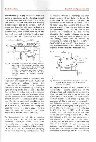
BARC New,Jetter Fouoder', Day SpedaJ )"oe 2002
conventional spark gap when used with thispulser is restricted, as the charging currenthas to be less than the holdover CUrrent ofthe switch. In the operation with rotatingdielectric spark gap as the switch, ~2kW ofpower was dissipated into a dummy load at arepetition rate of 300Hz [9). The fins on thedielectric disc, when rotated, blow air jet intothe spark gap and facilitate, thereby, suchhi9h repetition rate operation of the switch.
rCf--J;~;" ,;;-~'-l.:;''
r
~
t["~~~~j'~':~
""n ,;';n :.- I- -, .
., :"'=f\:.~:~
.LA
"'" 1::: :. .-'-- '~-'-:"-<:.,
Fig. 11 .- S,hematl, dlawam of the mtatlng dlele,t,;,,pa,k gap d,;ven ,..;"Ive/y ,harged pul,..along with opti,al ,en,o, ba,.d ";ggenng,'mu'a-y. 1 Rotating dlelectri, dl>c, 2. F;n"3. Moto', 4. Triggerable'pari<gap, 5. Tngg..,6. Load, 7. Pul,. lran>fom>er, 8. Optoele""'nlc ,.n,o" g. Cuffent amplifier,10.5CR
In the un-triggered mode of operation, thelarge jitter associated with the fluctuation ofthe breakdown voltage marred theperformance of the pulser. The triggering ofthe switch was accomplished by mounting alight emitting diode and a photo detectorface to face on either side of the rotatingdielectric in 5uch a way that whenever a holepassed between them another hole alsopassed between the electrodes of the sparkgap (Fig 11). At every such coincidence, thedetector received light from the emitter andgave out a pulse, which after processing wasused to trigger the spark gap. [n thetriggered mode of operation the jittersignificantlyreducedto ~ 25nsec [10].
As demonstrated in ref 11, a rotatingdielectric spark gap also has latch proofoperation capability when used withresonantly charged pulsers. However, suchan operation is not possible utilising a simplecircuit as of Fig 10 where the chargingresistance is replaced by an inductance. This
is because following a discharge the shortcircuit current (i) can build up during thetravel time of the hole (t) between theelectrodes of the conducting switch. For aTE laser load, this Current and hence theenergy stored in the charging inductor canbe appreciable [11). As the flow of thiscurrent is intercepted by the movingdielectric, the inductor releases the storedenergy causing the dielectric plate to ignite.The energy stored can be reduced byincreasing the value of L (as E = 'h (Li') =(V,'t2)/(2L), from eqn 6). This, however, isnot a practical soiution as it would be at theexpense of the achievable repetition rate.
.~oc
Fig. 12 , Short ,;~uit proof operation of the ,e,onantlych..ged pu/,e, when d,lven by a 'otatingdlelert,l, ,pa,k gap
An elegant solution to this problem is toincorporate a second spark gap in thecharging loop and rotate the same dielectricplate between the electrodes of both thespark gaps in such a way that holes appearin them exactly out of phase (Fig 12). Theoperation of this circuit can be explained inthe following manner. When a hole getsaligned with the charging spark gap SG2, itcloses allowing the condenser to be chargedto 2V, in a time (..J(LC) which is madesmaller than the travel time of the holeinside the gap by proper choice of L Afterthe passage of the hole, the appearance ofthe dielectric in the gap of this switchvirtually cuts off the power supply from therest of the circuit. A hole now appearsbetween the electrodes of the dischargespark gap (SG,) when it closes allowing thecondenser to discharge into the load. During
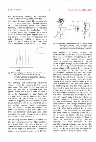
BARC Newsletter Found,,'s Day Special Issue 2002
and immediately following the discharge,which is normally very short lived for a TElaser load, the open switch SG, prevents anyshort circuit current Irom flowing throughSG.. The discharge switch thus readilyrecovers, as the Inductor now does not storeany energy during its conduction. Thecondenser would get charged once againwhen a second hole gets aligned with SG,and so on. In this mode of operation thepulser delivered -3.2kW of power at arepetition rate of 200 Hz into a dummy loadwhich resembled a typical TEA CO, laser.
l~ ~fl~
,moD
Fig. 13' Few cha'!]lng and dlscha'!]lng waveforms ofthe short drcult proof operation of theresonantly cha'!]ed pulser shown In F;g. 18.The Inset shows the cha'!]lng of the condenserIn an expanded "me scale.
Few charging and discharging waveformsshown in Fig 13 conform to the abovedescription. The Jitter in the operation ofboth SG, and SG, is apparent from thisfigure. When this pulser is used to drive alaser, the fluctuation in the closing ofcharging switch can be ignored, as it doesnot affect the performance of the laser.Therefore triggering of the discharge switchalone suffices which is accomplished usingthe optical sensor based mechanismdescribed in ref 9. Proper positioning of theholes with respect to the spark gaps suchthat the condenser discharges soon afteracquiring the peak voltage ensures droopfree operation with this device.
The rotating dielectric spark gap switch canalso drive simultaneously two high repetitionrate lasers [12]. The two lasers can beoperated synchronously or with a delay thatcan be as large as a millisecond. Schematicdiagram of the circuit is shown in Fig 14. The
tJi:i'. "..
~' '. <..
r'~ ""'--r ..0,",
r "'. ". ""'.. ".,0 <, h,.
i~.: U:r.-
Fig. 14 , Rotating dielectric spark gap as a d,;ver of tworesistively cha'!]ed high repetition ratelase~.Inset shows the positions of the holeswith respect to the d/scha'!]e gap SG, and SG,
same dielectric is rotated between the
electrodes of SG, and SG, in such a way thatholes appear In them simultaneously. SG,.triggered by the optical sensor basedtechnique, causes the condenser C, chargedto the supply voltage to discharge into theload R, while a pulse derived from this firstpulser triggers SG, causing C, to dischargeinto the load R,. A delay up to fewmicroseconds between the two dischargeshas been obtained by varying the value of I.The diodes D, and D, are required to isolatethe two discharge circuits. A larger delay,ranging from severai microseconds to morethan a millisecond, has also been obtainedby positioning SG, and SG, with respect tothe dielectric such that when a hole arrivesin SG" another hole is yet to arrive in SG,.The time interval between the arrivals of thetwo holes between the electrodes of their
respective spark gaps is the delay betweenthe two discharges. Triggering both SG, andSG, has considerably reduced the Jitter insuch operation. The voltage enhanced pulsefrom the optical sensor triggers SG, directlyand SG, after being delayed by a delaygenerator. The performance of this devicehas been tested by switching a total of 2.5kW of power at 200Hz into two identicaldummy loads resembling a typical TE laser interms of resistance. Though resistivecharging has been employed in thisoperation, resonant charging can be used forbetter efficiency. We note here that thistechnique can be, in principle, empioyed forsynchronisation of more than two lasers.

BARC New"e"" Found,,', Day Sp,,;al I"ue 2002
The unique geometry of the rotatingdielectric spark gap also allows diode-lessoperation of a command resonant chargingnetwork [13]. In a conventional switch,thyratron, spark gap or SCR driven resonantcharging pulser, the presence of diode ismandatory to arrest the flow of reversecurrent so as to maintain the voltage on thecondenser (refer to Fig 3a). These diodes,which should be capable of withstanding highvoltages and high currents, when form a partof the pulsers meant for repetitive operationof typical TE lasers are expensive and proneto damage, more so in the event of a shortcircuit. The principle of diode less operationcan be understood by referring to Fig 15.
.V,DC
F,g. 15, Diode-Ie» opeeetion of e ;osonently checgedpulsee netwo,k d,iven by e RD5G
SG, and SG, are so located that when thedielectric rotates, holes appear in themexactly out of phase. As a hole gets alignedwith SG,. it closes allowing the condenser tDget charged through L. If the time ofpassage of the hole between the electrodesDf SG, exactly equals the time taken by thecondenser to get charged fully (=n0(LC)) theappearance of the moving dielectric in thegap thereafter forces the switch to go intothe off state preventing the flow Df anyreverse current thus rendering the usage ofa Wade superfluous. As a second hole getsaligned with SG,. it closes and the condenserdischarges into the load. A pulser has beenoperated in this mode at a repetition rate of600 Hz with a dummy load resembling atypical TE laser. Few charging anddischarging waveforms at this repetition rateare shown in Fig 16. It would be seen that
the voltage Df the condenser has dropped toabout 90% of its initial value at the time of a
discharge. This indicates that some reversecurrent had flown through SG, before themoving dielectric appeared between itselectrodes and blocked it. Such a situation
can be overcome by adjusting the charge uptime of the condenser by making use of avariable choke or alternately by adjusting therotation speed of the motor.
I CHARGE
\DISCHARGE
//
/t
;:
--i'ms I- ,~
Fig. 16, Few che;ging end dische,ging wevefo,ms fo,the diode-less pulse,
The geometry of this switch allows an easyscalability of the maximum achievablerepetition rate. The repetition rate (f) in Hzhere can be written as
f = n x s (12)
where n is the number of holes on the discand s is the number of rotations per second.Increasing n or s or both, therefore, canincrease the repetition rate, however, up to acertain limit. If holes are taD close the
device no longer remains compatible withresonant charging. On the other hand, thespeed of rotation increases at the expense ofthe mechanical stability of the device.Further increase in the repetition rate ispossible by increasing the number ofdischarge gaps [14]. The schematic diagramof the circuit where a repetition rate of 1.2kHz has been achieved with a rotatingdielectric switch utilising two pairs ofdischarge gaps SG, and SG, is shown in Fig17. Reliable short circuit proof Dperation was
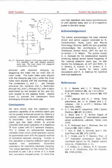
BARe New,'ett" 10 Found,,', Day Special I"ne 2002
<V '"'"
en
l
' 1J;""";~,,r, 0 0"
;)0I. IJ;~ 'no 0" 0 "
w, ~ 00 Of 00
Ei=UI T I. 1
-t:I-~~ '"~I",1-
[1J,0~
I~-~Ir,,""Fig. 17, Sd>ema"c diagram of the pulser used to ob~in
KHz repe""on ,,'e wnh ",~~ng dielectricspark gap. The in,el shows the >tagge,.dconfigura~on ofthe holes
achieved with resonant charging bystaggering the holes into an inner and anouter circle. The outer holes were alignedwith the charging gap (SG,) while the innerholes were aligned with the discharge gaps.The condensers e, and e, get chargedwhenever SG, conducts and e, dischargesthrough SG, and e, through SG, with a delaydetermined by the location of SG, and SG,with respect to the passing holes. DiodesD,and D, prevent the condensers fromdischarging through the same gap.
Conclusions
We have shown that the repetition rateoperation capability of an ordinary spark gapcan be greatly enhanced simply by rotating asuitably configured dielectric plate betweenits electrodes. Such a rotating dielectricspark gap has be.en shown to providecomplete latch proof operation of a repetitiveTE laser pulser with D-C resonant charging.This is indeed an achievement becausecomplete short circuit proof operation cannotbe guaranteed even with the popular methodof command resonant charging. Further inthis operation a rotating dielectric spark gapreplaces two (expensive) thyratronsmandatory for command resonant charging.The unique geometry of this switch has beenexploited to use it as a driver of i) a diodeless resonantly charged pulser, Ii) more than
one high repetition rate lasers synchronouslyor with desired delay and iii) of a repetitivepulser in the KHzrange.
Acknowledgement
The author acknowledges the keen interestshown and active support extended by N.Venkatramani, Head, Laser and PlasmaTechnology Division, BARCHe also gratefullyacknowledges the contributions of U.K.Chatterjee, former Head, L&PTDiv and hisco-worker ]. P. Nilaya. The author thanksB. S. Narayan for his coilaboration towardsachieving optical sensor based triggering ofthe rotating dielectric spark gap. He alsothanks his coileagues, at CATand BARC,N.S. Benerjl, A. Kumar, S. K. Sarkar, A. K.Nath, and U. Nundy for many usefuldiscussions and R. A. Nakhwa for excellenttechnical assistance.
References
1. D. ]. Biswas and ]. P. Nilaya, Prog.Quantum Electron 26, pp [-63 (2002)
2. P. K. Bhadani, Rev Sci Instrum 60, 605(1989).
3. ). V. Lebacqz and H. ). White, Pulsegenerators, ed: G. N. Glasoe and ]. V.Lebacqz , Vol 5, p-275 ( McGraw Hill,NewYork, 1948).
4. R. C. Sze and E. Seegmiller, IEEE] QuantElectron, QE-17, 81(1982).
5. S. Black and T. R. Borkes Digest ofTechnical papers, 2"' international pulsedpower conference, Lubbock, Texas, June1979.
6. K. R. Rickwood and ). McInnes, Rev SciInstrum 53,1667 (1982).
7. T. Kan, D. Ball, E. Schmitt, and ]. Hill,Appl Phys Lett 35, 676 (2979).
8. G.]. Scoles and B. P. Newton, Proc of11'" modulator symposium, Sept 1973(technical reprint no 78, English electricvalve co., Chelmsford, U. K).
9. ). P. Nilaya, D. ). Biswas, B. S. Narayan,and U. K. Chatterjee, Rev Sci Instrum,65, 3590 (1994).
BARC New,lett" II Found,,', Day Speeial "me 2002
10.J. P. Nilaya, Ph.D thesis, University ofMumbai (2001). D. J. Biswas, J. P.Nilaya, and U. K. Chatterjee, Rev SelInstrum 66,4813 (1995).
1l.D. J. Biswas, J. P. Nilaya, and U. K.Chatterjee, Opt Eng 36, 588 (1997).
12. D. J. Biswas and J. P. Nilaya, Rev SeiInstrum 72, 2505 (2001).
13. J. P. Nilaya and D. J. Biswas, Proe ofNational laser symsposium, PRL,Ahmedabad, India, p-48 (1998).
Dr Dhruha J. Biswas was conferred the Homi Bhabha Science & TechnologyAwardfor the year 2000 for his outstanding contributions in laser technology andrelated fie/ds.
About the author...
D, Dh,uba J. Biswas ,ecelved hi, ".Sc
e"twhile "DRS, BARC In 1979 afte, goaowoek on optical chao> fetched him the doctocate1986 whe,e he wa> on a two-yeac "bbatical.
technology of mld-infmed ga> la"" Includphy,lcal pmce"e,. He ha, to hi, coedit 64intemational phy,feal joumal,. He i, a
t of the INSA young "ienti"N. S.
BARC Newslet." 12 Founder's Day Speciallssue 2002
Design and Development of DriveMechanisms for Adjuster Rods, ControlRods and Shut-off Rods of Tarapur AtomicPower Projects-3&4Manjit Singh, D. N. Badodkar, N. K. Singh, N. S. Dalal, M. K. Mlshra,C. B. Kothari, and G. Veda VyasDivisioo of Remote Haod"09 & RoboticsBhabha Atomic Reseacoh Ceotee
Introduction
BARC and Nuclear Power Corporation ofIndia LId (NPCIL) had entered intoMemorandum of Understanding (MoU) fordesign and development of drivemechanisms for adjuster rods, control rods &shut-off rods of Tarapur Atomic PowerProjects-3&4. The development work wastaken up at DRHR,BARe.
An electromechanical, cable winch type drivemechanism with advance features has beendeveloped for this purpose incorporating anumber of advanced features. Design of thismechanism is significantly different from themechanisms used in Dhruva, Kaminiand 220MWe PHWR's.
A prototype drive mechanism has beenmanufactured, assembled and tested on full-scale test station at BARe. The prototypemechanism has been tested for its functionaltesting, performance optimization and lifecycle testing for design validation. Aftersuccessful testing, the design includingdetailed drawings, technical specificationshave been issued to NPOL for production ofdrive mechanisms for reactor use. Testresults during development and qualificationstage have also been issued to NPCIL.Thisdevelopment work at BARC was alsoorganized to meet the TAPP-3&4 projectschedule requirements.
Functional Requirements
The drive mechanism is designed to meetthe followingfunctional requirements:
. Raising, lowering & holding of the rod
. Position indication: continuous and endlimits. Scram characteristics. Size constraints. Environmental conditions. Remote engagement/disengagement. Limited reactivity addition capability
. Fail-safe, non-reverse scram character-istics. Service life requirements
. Trips, alarms & indications to check safeoperation &healthiness
. Reliable, non-dependent on externalpower source for safety action. Minimum periodic maintenance
Description
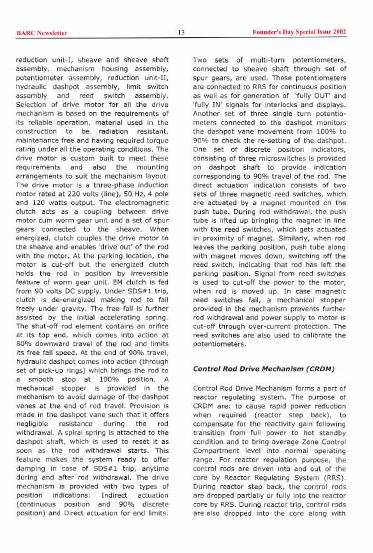
Shut-off Rod Drive Mechanism (SRDM)
Shut-off rod drive mechanism forms a partof Shut Down System No.1 (SDS#I). Thepurpose of this is to provide shutdowncapability to the reactor, when desired,under normal operating conditions as well asunder undesirable conditions in the plantwhich calls for a reactor trip, with adequatemargin so as to hold the reactor in shutdown condition for prolonged period.
SRDM, being the most important safetysystem of the Nuclear Power Plant, It callsfor a very high reliability of operation as wellas effectiveness, which are mainly governedby its ability to operate within a very shortinterval and the magnitude of the negativereactivity worth it can impart to the reactor.The shut-off rod drive mechanism consists ofa drive motor, worm gear unit, anelectromagnetic clutch, set of spur gears as
BARC New"e"" 13 Found,,'s Day Special I"ue 2002
reduction unit-I, sheave and sheave shaftassembly, mechanism housing assembly,potentiometer assembly, reduction unit-II,hydraulic dashpot assembly, limit switchassembly and reed switch assembly.Selection of drive motor for all the drivemechanism is based on the requirements ofits reliable operation, material used in theconstruction to be radiation resistant,maintenance free and having required torquerating under all the operating conditions. Thedrive motor is custom built to meet theserequirements and also the mountingarrangements to suit the mechanism layout.The drive motor is a three-phase inductionmotor rated at 220 volts (line), 50 Hz, 4 poleand 120 watts output. The electromagneticclutch acts as a coupling between drivemotor cum worm gear unit and a set of spurgears connected to the sheave. Whenenergized, clutch couples the drive motor tothe sheave and enables 'drive out' of the rodwith the motor. At the parking location, themotor is cut-off but the energized clutchholds the rod in position by irreversiblefeature of worm gear unit. EMclutch is fedfrom 90 volts DC supply. Under SDS#l trip,clutch is de-energized making rod to fallfreely under gravity. The free fall is furtherassisted by the initial accelerating spring.The shut-off rod element contains an orificeat its top end, which comes into action at80% downward travel of the rod and limitsits free fall speed. At the end of 90% travel,hydraulic dashpot comes into action (throughset of pick-up rings) which brings the rod toa smooth stop at 100% position. Amechanical stopper is provided in themechanism to avoid damage of the dashpotvanes at the end of rod travel. Provision ismade in the dash pot vane such that it offersnegligible resistance during the rodwithdrawal. A spiral spring is attached to thedash pot shaft, which is used to reset it assoon as the rod withdrawal starts. Thisfeature makes the system ready to offerdamping in case of SDS#l trip, anytimeduring and after rod withdrawal. The drivemechanism is provided with two types ofposition indications: Indirect actuation(continuous position and 90% discreteposition) and Direct actuation for end limits.
Two sets of multi-turn potentiometers,connected to sheave shaft through set ofspur gears, are used. These potentiometersare connected to RRSfor continuous positionas well as for generation of 'fully OUT' and'fully IN' signals for interlocks and displays.Another set of three single turn potentio-meters connected to the dash pot monitorsthe dashpot vane movement from 100% to90% to check the re-setting of the dashpot.One set of discrete position indicators,consisting of three microswitches is providedon dashpot shaft to provide indicationcorresponding to 90% travel of the rod. Thedirect actuation indication consists of twosets of three magnetic reed switches, whichare actuated by a magnet mounted on thepush tube. During rod withdrawal, the pushtube is lifted up bringing the ma9net in linewith the reed switches, which gets actuatedin proximity of magnet. Similarly, when rodleaves the parking position, push tube alongwith magnet moves down, switching off thereed switch, indicating that rod has left theparking position. Signal from reed switchesis used to cut-off the power to the motor,when rod is moved up. In case magneticreed switches fail, a mechanical stopperprovided in the mechanism prevents furtherrod withdrawal and power supply to motor iscut-off through over-current protection. Thereed switches are also used to calibrate thepotentiometers.
Control Rod Drive Mechanism (CRDM)
Control Rod Drive Mechanism forms a part ofreactor regulating system. The purpose ofCRDMare: to cause rapid power reductionwhen required (reactor step back), tocompensate for the reactivity gain followingtransition from full power to hot standbycondition and to bring average Zone ControlCompartment level into normal operatingrange. For reactor regulation purpose, thecontrol rods are driven into and out of thecore by Reactor Regulating System (RRS).During reactor step back, the control rodsare dropped partially or fully into the reactorcore by RRS. During reactor trip, control rodsare also dropped into the core along with
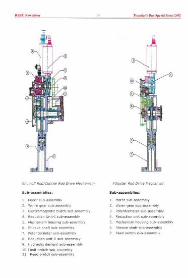
BARC N,w,',"" 14 Fallad,,', D', Sp,dal "'"' 2002
5hu'~Dff Rod/Contra! Rod Drive Mechanism
Sub~assemblies:
1. Motoe sub~assembly
2. Worm gear sub~assembly
3. Electromagnetic clutch sub~assembly
4. Reduction Unit~I sub~assembly
5. Mechanism housing sub~assembly
6. Sheave shaft sub~assembly
7. Potentiometer sub~assembly
8. Reduction unit~II sub~assembly
9. Hydeaulic dashpot sub~assembly
10. Limit switch sub~assembly
11. Reed switch sub~assembly
Adjuster Rod Drive Mechamsm
Sub~assemblies:
1. Motor sub~assembly
2 Worm gear sub~assembly
3. Potentiometer sub~assembly
4. Reduction unit sub~assembly
5. Mechanism housing sub~assembly
6. Sheave shaft sub~assembly
7. Reed switch sub~assembly

BARC New,le"" 15 Found,,', Day Spedal "'ne 2002
shut-off rods of shutdown system no. 1(SDS#l).
The drive mechanisms for control rods andshut-off rods are identical. However, theabsorber element for control rod differs from
that of shut-off rod. The bottom attachmentof shut-off rod is fully open while that ofcontrol rod contains an orifice plate to limitits free fall speed.
DROP CHARACTERISTIC OF SHUT-OFF ROD FOR TAPP-3&4
1009060
~ 70
Ji 60~ 50
~ 40
~ ;gt:::;100
0 0.5 1.5
4.5
4 -3.5 g3 'ii25 ~2 815 ~1 '80.5 n:0
4.5
,---uuuu,-
-'---uuu_L_u
--u' "----
2.5 3.5
omp chacactec!,hc of Shut-off Rod fo' TAPP-3&4
Hme I,ec.)
Seal Te>t Rig
Full Scale Te" Station

BARC New,'etter 16 Founder', DRY Speciall"oe 2002
Ji
'1M.Fl~D~'1M."""'A'U"
Fl~D TO"'£AtED, HElIU"Fl~O I'RfSSU" ,0.85 ";om2 I,)Fl~D ""PERATURE, OS' C
AT". FlUIU~AT". "MPERATO"
- MECHANISMHOU"NG
---~.-BAlL BEARING
SEAL f.SSY-SHEAVE
MECHANICALSHAFTSEALS FOR SHEAVESHAFT
ATM.Fl~D . N'ATM.""$SO" ,'.44 ',/,m2ATM.""'ERA'U" ",. C
DASHPOI
GEAR
FlU,"TO" SEAlED.0"FlUIU""ESSU" 14',/,m2 I,)FlUIU """RATORE. ". C
'1M FlU'D~'1M. ""'ERATU"
Df.SHPOT SHAFT
OASHPOT HOUSING
BALL BEARINGDASHPOT COvrR
MECHANICALSHAFTSEALS FOR HYDRAULICDASHPOT
6 ANTI-ROTATIONPIN 5.5.3165 '0' RING VlTON
4 SLEEVE 5.5. 17-4 PH
3 MATINGRING COM 'R!i\lING T.C.+ TITANIUM
2 '0' RING VlTON1 SEAL ASSY. (STATIONARY CARBON FACE
S.No DESCRIPTION MATERIAL
BARC Now,I,Uer 17 Founder', Day Sp,ciall"n, 2002
Adjuster Rod Drive Mechanism (ARDM)
Adjuster rod drive mechanism forms a partof RRS.The purpose of ARDMare: to provideXenon override capability during reactorstart-up, flux flattening and reactivity shimduring extended fuelling machine outages.During normal reactor operation, adjusterrods remain within the reactor core. Forregulating purpose, the adjuster rods aredriven out and into the core by RRS, as andwhen required.
Adjuster rod drive mechanism is designed forraising and lowering of adjuster rods atcontrolled speeds and does not containelectromagnetic clutch or hydraulic dashpot.
ARDMconsists of drive motor, worm gearunit, potentiometer, set of spur gears asreduction unit, sheave and sheave shaftassembly, mechanism housing assembly andreed switch assembly.
Basic design specifications are given inTable-1.
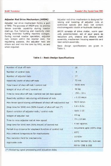
Table 1 : Basic Design Specifications
BARC New,]e"" 18 Found,,'s Day Spedal '"ue 2002
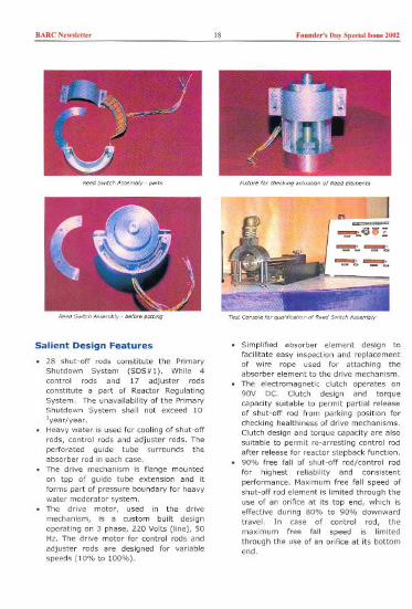
,,'" Switch'e~mbly~,'n<
Reed Sw<ch Ao~mbly~belo,e pOCtlog
Salient Design Features
0 28 shut-off rods constitute the PrimaryShutdown System (SDS#I). While 4control rods and 17 adjuster rodsconstitute a pact of Reactor RegulatingSystem. The unavailability of the PrimaryShutdown System shall not exceed 10~'year/year.
0 Heavy water is used for cooling of shut-offrods, control rods and adjuster rods. Theperforated guide tube surrounds theabsorber rod in each case.
0 The drive mechanism is flange mountedon toP of guide tube extension and it
forms part of pressure boundary for heavywater moderator system.
0 The drive motor, used in the drive
mechanism, is a custom built designoperating on 3 phase, 220 Volts (line), 50Hz. The drive motor for control rods and
adjuster rods are designed for variablespeeds (10% to 100%).
FixW,' foc ,h"king ,,",,"on of P'ed fl,m,,"
Td Coneole 1m Omllh""o, of Reed SWltcl, A"'mbly
0 Simplified absorber element design tofacilitate easy inspection and replacementof wire rope used for attaching theabsorber element to the drive mechanism.
0 The electromagnetic clutch operates on90V DC. Clutch design and torquecapacity suitable to permit partial releaseof shut-off rod from parking position forchecking healthiness of drive mechanisms.Clutch design and torque capacity are alsosuitable to permit re-arresting control rodafter release for reactor stepback function.
0 90% free fall of shut-off rod/control rodfor highest reliability and consistentperformance. Maximum free fall speed ofshut-off rod element is limited through theuse of an orifice at its top end, which iseffective during 80% to 90% downwardtravel. In case of control rod, themaximum free fall speed is limitedthrough the use of an orifice at its bottomend.

BARC New"e"" 19 Found,,', Day Speda! '"ne 2002
. Hydraulic dashpot incorporates an oilwindow connected to low pressure side.
Above the oil level, window has adequatespace for expansion of oil at high ambienttemperature.. The conventional single vane replaced bydouble vane to balance forces on dashpot
shaft arising from high oil pressure duringdamping action.. A screw for controlling oil bypass fromhigh pressure side to low pressure side foradjusting damping characteristics ofdash pot.. Modular design of drive mechanism layoutto permit in-situ maintenance/replacement for individual sub-assembliese.g. motor and worm gear, clutch,dash pot, switchgear, potentiometer etcwithout opening moderator pressure
boundary.. Better lubrication for gears, bearings,
pick-up rings and spiral springs for longwear life.. Rope sheave in place of rope-drum toeliminate chances of wire rope coming off
the drum groove.. Provision of single turn triplicate
potentiometer on dash pot shaft to monitorretrieval of spiral spring while the rod isbeing raised. Raising of the rod will getinhibited incase of unsatisfactory retrieval
of dash pot shaft. Rationality checks onpotentiometer signal shall be done todetect potentiometer failure.. Provision of multi-turn dual potentiometer
to monitor continuous position of rods.Rationality checks on potentiometer signalshall be done to detect potentiometerfailure.. Provision of rugged triplicated switchgearunit to monitor shut-off rod drop time for90% fall.. Gear reduction trains for potentiometerand limit switches are eliminated.. Provision of one set of triplicated reed
switches (directly actuated) to indicateshut-off rod fully out position and to cut-off the drive motor power. Second set ofreed switches are used for RRS.
Testing of Prototype DriveMechanism
Testing for Performance and Design
Optimization
. Testing for full travel to establish the drivemotor rating.. Testing of EM Clutch for optimum
performance (Minimum voltage at whichthe rod slips, delay time, temperature riseof the coil under continuous operation,
effect of elevated temperature aroundmechanism, etc.).
. Optimization of orifice in the topattachment of shut-off rod element for rod
drop dynamics.. Effect of water level variation in tank
(calandria) on rod drop dynamics.. Optimization of orifice in the bottomattachment of control rod element for rod
drop performance and clutch re-setting forpartial drop qualification.. Optimization of partial releasecharacteristics of shut-off rod for on-line
testing.. Performance testing of dashpot using oilof different viscosity, effect of internalclearances, effect of oil by-pass screw
adjustments on rod drop dynamics andeffect of elevated ambient.. Rod drop characteristics with tank water(simulating calandria) at 80'C and
elevated temperature around mechanismto 55'c.
Qualification of Special Hardware Itemson Test Rigs
. Simulated testing and qualification of
dynamic shaft seals used in sheavechamber & dashpot for 50,000 cycles.
. Simulated testing and qualification ofspiral spring, rotary switch-gear (LimitSwitch) and potentiometers for 10' cycles.
. Simulated testing and qualification of reedswitch unit for lac cycles.. Qualification of drive motor and electro-magnetic clutch.. Qualification of wire rope & its crimpedterminals (swaging is done using portablepneumatically operated cable swager).
BARe News'd'" 20 Found,,'s Day Spedal hsue 2002
Life Cycle Testing for DesignQualification
In order to qualify the design, prototypedrive mechanism has been manufactured,assembled and tested on full-scale teststation at BARe.
. Prototype SOR P-I! has been successfully
tested for more than 5000 drops fordesign validation and optimisation ofscram characteristics, resulting inconsistent performance.. On-line testing of SOR P-I! has also been
successfully completed for more than3000 cycles. During on-line testing, rodwas held at park 'UP' position and thevoltage to EM clutch was reduced to zero
for short time. In each cycle, rod was
released to fall three times consecutively(by pressing the trigger three times) andthe rod travel was noted down. Rod travel
corresponding to first trigger in each cycleis spring assisted. After releasing the rodthree times, rod is taken up by the drivemotor till it reaches the park 'UP' position.
This completes one cycle. Thus, duringon-line testing foe 3000 cycles, rod hasbeen released for total 9000 times. The
rod travel corresponding to I", 2"' and 3"triggec was around 100mm, 70mm and70mm respectively. Results showedconsistent performance.
. Partial release test of Control Rod (forstepback function) for about 60% travelhas been successfully completed for about1000 cycles.. Prototype adjuster rod drive mechanismhas been successfully cycle tested formore than 5000 cycles.
References
Design Basis Report on Shut-off RodMechanism: TAPP-3&4/DBR/31450101 Rev. 2
Technical specification for manufacture ofdrive mechanisms of TAPP-3&4: No. PB-E-610.
Technical specification for Drive motor ofSRDM for TAPP-3&4: No. PB-E-625
Test Report on Life Cycle testing of SOR forTAPP-3&4, Issue: Aug. 2001Test Report on 'On-line testing of SOR forTAPP-3&4', Issue: Nov. 2001
Acknowledgement
The team members of Control MechanismSection, DRHR, are grateful to the Head,DRHR,for giving the opportunity to work onthis development work and giving guidanceon regular basis.
Members of CMS, DRHR, are also thankful tothe Director, A&MG and E&IG, for hiscontinuous encouragement and support.
Mr D.N. Badodkar was conferred the BARC Technical Excellence A wardforthe year lOOOfor his highly commendable contributions in the.field of specialpurpose drives and reactor control mechanisms.
About the autho" ..

BARC New,]e"" 21 Foond,,', Day Speda! 1>,0e 2002
Mr D. N. Badodkar of Ow,"/on of Remote Hand!;ng & Robobcs, BARC, was mnfecced the 'BARCTechnical Excellence Award-2000' on 30.10.2001 Mr Badodkar Is heading the 'Cont,ol Mechanism
Secbon' of DRHR Peesently, M, Badodk.. Is wooklng on the design and development of O,lve
N.K. 5mgh
N.5. Dalal
MK Mlsh"
CB Koth..1
Mr N. K. Singh and Mr M. K. Mishra of CMS, ORHR, have wooked on mechanical
design of d,lve mechanism fo, TAPP-3&4, test-,igs fo, of "b-",sembl/es and they wece cloooly associated with design and life cycleIesbng of pcotolype on full scale lest stabon.
Mr N. S. Dalal, and Mr C. B. Kothari of CMS, have wo,ked on the testmnsole foe design ,,!;dabon and life tesbng mechamsm fo, TAPP-3&4, lest set-up for qua!;bcabon and they wece assoclaledfo, pecto,mance and !;fe cycle tesbng of pco"'ype on full scale
Iesbng of d,ive mechanism fo,and dashpot pecto,mance
Mr G. Veda Vyas of CMS, oRHR, has been assoclaled fo, life
TAPP-3&4. He," wo,klng on develop.fa, the shut-off cod d,ive mechanism
"
BARCN,w,',"', 22 Foond,,', Day Spociolh,o' 2002
Ion Accelerator FacilityFolded Tandemat BARC
Pitamber SinghN""e" Phy,i" Pi"SiocBhabha AtomicR""ceh Centee
Abstract
The Foloed Tandem [on Acce/eeator (FOnA) facmty has been commissioned recently at BARe. Several beams
('H, 'u, "c, "0, HF) have been accelerated upto a teeminal vol"'ge of 3 MV with N,+CO, as Insulating gas.The terminal vol"'ge is staNU"d within I 2 kV. The beams are used for elemental analysis using the
Rutheetord Bock Sc"tering (RBS) technique. Atter making a few measuremen" around this terminal voltage,SF, will be filled ,n the a"eleeator tank in ofdee to ",se the teeminal voltage to 6 MV. Some of the saUentfeatur" of the FOTIA facility are discussed hece.
In the last few decades,low energy accelerators,capable of delivering lightand heavy ion beams,have played an importantrole both in basic andapplied sciencesparticularly in the fieldsof astrophysics, materialscience, accelerator massspectrometry, beam foilspectroscopy, etc.
Although there are alarge number of Van-de-Graaff acceleratoes indifferent laboratories onlya few of them have beenconverted into foldedtandem accelerators [lJ,A project [2] was takenup at BARCto nvert theexisting 5.5 MVModelCNsingle stage Van-de-Graaff accelerator,which was in continuous operation since1962 at the Nuclear Physics Division, into a 6MVFolded Tandem Ion Accelerator (FOTIA),Due to limited power available in theterminal it was possible to produce andaccelerate beams of only Wand He. ions inthe old Van-de-Graaff accelerator at BARe.
Introduction
"0' 'ENDINa .AaNET
CORONASTABI""Na SYSTEM
EL QUAU. OOUBLET
Fe-'
..
Ag. " Schematic diagram of the Folded Tandem [on A"elecator
However, FOTIA can accelerate heavy ionbeams of up to A.40 and energy up to 60MeV.
Description of the FOTIA Facility
The layout of the FOTIA(Fig,l) was workedout by optimizing the ion optics parameters[3] despite severe geometrical constraints

BARC Newsletter 23 Founder's Day Spedal Issue 2002
due to the utilization of the existinginfrastructure of the Van-de-Graaffaccelerator. One of the novel features of theion optics IS introduction of an einzel lens atthe entry of the low energy tube. With this inoperation it will be possible to get goodtransmission even at very low terminalvoltages. This has contributed to theenhancement of dynamic range of itsoperation. In view of the modification in thebeam optics, it was found necessary to raisethe high voltage column structure by 1 m toaccommodate, at the exit of the high energyaccelerating tube, the additional magneticquadrupole triplet and steerer magnetswhich are essential for optimum transmissionof the beam. A tank raising structure (1mlong, 2.5 dia.) has been incorporated in thesystem. This was really a challenging task asthis additional collar had to withstand a load
of 18 tons due to pressure vessel, highvoltage column section, 180' magnet,alternator, ete. Also, the structure had to bebuilt in two halves as otherwise it was notpossible to take it to the accelerator room onthe first floor of the Van-de-Graaff building.
~
Fig. 2 SNICS II wn ooucce
The FOTIA is an accelerator amongst a fewof its kind in the world. The construction of
FOTIA involved development of technologiesof several important components like:. dipole magnets,. high voltage generator,. electrostatic and magnetic focusing lenses. steering devices,. vacuum systems,. SF6 gas handling system,. computer control system
In FOTIA, the negative ion beams extractedfrom the SNICS- II source (Fig,2) are pre-accelerated up to 150 keV. Out of all thecharged particles extracted from the ionsource the negative ions of the desired massare selected using a 70°-dipole magnet forinjection into the low energy acceleratingtube.
F'g. ], The 70' pee inleeto. m'gnet
As can be seen in Fig. 1, three dipolemagnets [2J are used in FOTIA and theirparameters are given listed in Table 1. The700-magnet (Fig.3) is designed for amagnetic field of 14 kG in the pole gap of 4em and has a bending radius of 40 em. Itcan bend the ions having mass-energyproduct (ME/q') $ 15. A magnetic field of
14.5 kG was realised, with field uniformity oft 0.1%, at a current of 180 Amp.
Several beams were extracted from the ion
source and then ana lysed using the 70'-magnet. Analysed beam currents of severalmicroamperes (H'(4.5 "A), U'(0.5 "A), C(5

BARC New,l"t" 24 Found,,'s Day Special h..e 2002
Table 1: Design parameters of the dipole magnets
eA), 0(24 eA), 5i'(13 eA), CI-(11 eA)) were
obtained. A typical mass spectrum obtainedwith Fe,O, cathode sample is shown inFig. 4.
10' -c--c--cur- ~--.
~ I,",""="wpl,F,P,10'
~ 10'.~
§.:5
HI'
IU" so 75 100 us ISO !7S
Magnetcumnt(Amp)
Fig 4. Ma" spe"cum foe Fe,O, cothode "mple
The beams are injected into the low energyaccelerating tube through a 20°-electrostaticdeflector. An electrostatic quadrupole tripletand an einzel lens are used to focusand match the beam parameters to the
Parameter 70' lSOo 90'
(A) CORE DETAILS
Air oao(mm 40 15 40GaD width mm 100 42 110Bendinn radius mm 400 305 750GaD field(KG 14 14 14Field uniformitv(%) 0,10 0.15 0.10Pole neometrv ANAC NORMAL ANAC(8) COIL DETAILS
Material CoDoer Coooer CoooerConductor Strip Strip Hollow Copper tubesSize mm x mm 0.80x75 0.78x50 12x12No. of coils 2 2 2No. of turns nee coil 150 75 56Resistance Der coil 85 mn 75 mn 40 mnCurrent capacity 200 amp 120 amp 500 ampInter-turn insulation M lar Nomex Fiber olassMax. coil temp 70° SO' 70"

BARC Newslettor 25 Founder's Day Speelallssne 2002
acceptance of the low energy tube. Theelectrons of these accelerated negative ionsget stripped off at the stripper and a desiredcharge state of the positive ions thusproduced Is selected with the 1800 magnetinside the high voltage terminal before beingbent into the high energy accelerating tubewhere they are further accelerated.
The 180'-magnet (Fig.5) (ME/q'=10, R=30.5em) has been tested for its field uniformity,which was found to be > 0.15%. A magneticfield of 10.2 kG was measured at 100 Amp.
fig. 6 .. The 90' - 'n'lvzlng m'one'
At the exit of the 180° magnet the beamdiverges. An electrostatic quadrupole doubletis used to focus the beam before it entersthe high-energy tube. The beamsaccelerated in the high energy acceleratingtube are focussed using a magneticquadrupole triplet (MQT) before beinganalyzed by the gOo-magnet (Fig.G). ThegOo-dipole magnet is designed for amagnetic field of 14 kG and ME/q'=50 with aradius of curvature of 75 cm. A magneticfield of 15.5 kG was obtained at 500 Amp(Fig.7).
_I")1:;- 12~-ij 8~
~4
.. 100 200 JOO 400
Magnet current (Amp)
500
Fig. 7 .. Magneue field V5 coil cum,"t for the 9(1' magnet
The ana lysed beam is transported to thescattering chamber through the experimentalbeam line, which consists of MQT, switchingmagnet, magnetic steerer [4], beam profilemonitors (BPM), Faraday cups (Fe), etc.These components (MQT, the magneticsteerers (Fig.8), BPM, Faraday cups) wereobtained either from local vendors ordesigned and fabricated in BARe.
Fig.8 .. Magnelie steerer designed and boUt for FOTIAbeam line
In Table 2, final beam energies, ME/q'values and relative intensities of different
charge states produced at the foil stripper inthe terminal are listed. The FallA facility hasbeen commissioned recently [5] and all thecomponents (low and high energy beamlines, high voltage column section, chargingassembly, SF, gas handling and computer

BARC New,le"" 26 Foond,,', Day Spedal I"oe 2002
Table 2 : The final beam energies at a terminal voltage of 6 MVfor ions with differentcharge state (q)
control systems, magnets, electrostatic andmagnetic lenses, steerers, scatteringchamber, etc.) has been workingsatisfactorily [6].
CommissioningFacility
of the FOTIA
The commissioning of the FOTIA basicallyinvolved: a) design, fabrication, installation
and testing of its sub-systems, b) highvoltage tests, c) beam trials and theircharacterization, and d) calibration of the gO"analyzing magnet.
High Voltage Tests
The high voltage system of the FOTIA
consists of different components like highvoltage column section, charging mechanismand measurement & control system.
The high voltage column section consists of
six modules (Fig.9); each designed for onemillion volt. Each module has 4 ceramic
insulating posts, which are ceramic to metal
bonded with 18 corona gaps connected byequipotential hoops. A pellet chain charging
system, made of metallic pellets and nylonlinks, is used for generating the voltage onthe terminal. The electrical power, requiredin the terminal, for IS00-magnet, ion pump,foil and gas strippers, electrostatic
quadrupole doublet, Faraday cup and otherelectronic components, is generated by the5 KVA alternator. The maximum vibration
amplitude with both Perspex shaft and pelletchain running was found to be less than 30 u[7J (Fig.l0), which was within the safe limit.
Ion Z q+ Relative Ee(MeV) ME/q' Ion Z q+Rel:ive I E, (MeV) ME/q'l%
'H 1 1 100 12 12 "51 14 5 16 36 40'He 2 2 100 18 18 6 34 42 33"c 6 3 12 24 32 7 31 48 27
4 52 30 23 8 13 54 245 33 36 17 "5 16 6 28 42 37
'"0 8 4 24 30 30 7 34 48 315 47 36 23 8 19 54 276 23 42 19 "CI 17 6 29 42 -
"Mo 12 4 30 45 7 33 485 24 36 35 8 18 54 276 39 42 32 "Ca 20 7 31 48 397 25 48 24 8 26 I 54 348 6 54 20 9 12 60 30

BARC Newslett" 27 Founder's Day Spedal Issue 2002
The high voltage measurement system of theFOTIA uses a generating voltmeter (GVM)mounted on the inside surface of the tank, infront of the high voltage terminal. The highvoltage control system uses a corona probemounted inside the tank opposite to theGVM. The high voltage tests were carried outusing N,+CO, mixture as an insulating gas.At a tank pressure of 98 psig, a sustainedvoltage of 3.4 MV was achieved [8].
ie,
J , ~ 3"" """""","""=)
Fig.lO Vib,ati,n amplitude a"M5 the column section
In FOTIA, SF, will be used as insulating gas.Since hydrocarbon free environment isrequired inside the accelerator tank oil freeequipments are used. The new gas handlingsystem [9] consists of an oil freecompressor, a centrifugal blower, a heatexchanger, dust filters, dryers and a vacuumpump ete. The gas handling system, is usedmainly: a) to transfer gas from storage tankto accelerator tank and vice versa. b) toevacuate the accelerator tank to a pressure-0.5 Torr. This maintains purity of gas by
minimizing the contamination of the gas byresidual air c) to remove moisture andbreakdown products by re-circulating gas ina close loop system containing activatedalumina dryer, heat exchanger, blower andfilters, d) to maintain the temperature,inside the accelerator tank, to its designedvalue.
The accelerating tubes are subjected to veryhigh voltage gradient of about 2 MV/m,
which requires a hydrocarbon free and cleanvacuum for smooth operation of theaccelerator. A distributed pumping systemhaving eight pumping stations has been usedto maintain UHV in the entire accelerator
including an experimental beam line and thescattering chamber [10]. The type of thepumps installed in a particular section isbased on the gas load in that section (Table3). The vacuum chamber of the 180' magnet(Fig. 11) has been provided with a separateion pump, as its cross section (14 mm x 24mm) is small. The ion source section has alarge gas load, which increases substantiallywhenever samples are changed in the ionsource. A turbo-molecular pump, with thespeed of 1600 litres/sec, is used to maintainultra high vacuum in this region. The othersections are pumped by a combination oftitanium sublimation and sputter ion pumpsor only by sputter ion pumps. A vacuum of 8x 10" Torr was achieved in the entiresystem.
Fig. 11 : Vacuum chambe, (octhe 180' magnet
Voltage stabilization system
In tandem accelerators, the energy of thebeam depends on the terminal voltage V,and charge state q of the ions. The terminalvoltage stability therefore determines theenergy spread of the beam. A terminalvoltage stabilization (TVS) system [l1J wasdesigned and developed for the FOTIAfacility, and has been used extensivelyduring beam trials. It is a closed loop controlsystem, which involves measurement andmonitoring of terminal voltage, beam energyand their stabilization. The present control &
:
II
BARC Newsle"" 28 Foood,,'s D,y Sped" Issue 2002
Table 3: Gas load estimates
. 820 = 700 (TSP) * 120(SIP), ..1640 = 1400 (TSP) + 120(SIP)Note, TSP pomps oce pot 00 ooly wheo they", "ooired.
monitoring system consists of GVM and its
amplifier, a slit amplifier and a corona probedrive controller circuit. The TVS systemworks in two modes namely: a) GVM controlmode and b) slit control mode.
The generating voltmeter (GVM) is used tomeasure the terminal voltage. In GVMcontrol mode, the TVS controller generatesan error signal by comparing the terminalvoltage reading from the GVM amplifier withthe set reference. In FOTIA, 900 magnet isused to analyse the beam and determine its
energy, which in turn is used to obtain the
terminal voltage V,. Any change In V, willreflect on the beam position at the exit ofthe analyzing magnet. A slit system locatedjust after the analyzing magnet monitors thebeam position by measuring the current
pick-ups on low energy and high energyslits. In the slit control mode, the TVScompares the low and high energy slitcurrents and generates an error signal whichis used for locking the beam position. Thecorona probe controller works as a shuntregulator by loading the charging system. Inboth the cases, corona probe controller usesthe error signals for stabilizing the terminalvoltage.
The TVS system regulates terminal voltageover a wide range of its operation. The TVScontroller also incorporates the facility tomonitor various signals like terminal voltage,corona probe current, grid voltage and slitpick-ups. The system was tested both inGVMcontrol mode and slit control mode witha beam current as low as 2 nA and its
Section Name of Main components Volume Gas load PumpingNo. the section (em') & (Torr-lit/see) speed (lit/s)
surface
;::.a,\1. Ion source Ion sou rce, Ace. 47713
Tube, E.S. steerer 1.44 x la' 160010822
2. Injection line BPM, FC, 51616
70' Magnet 6.3 xl06 820 *Chamber, 19287
20' Deflector, E.5.Steerer
3. Low energy Einzel lens, Ace. 22407accelerating Tube, E.S. Steerer, 1.08 X 10⁻⁶ 120tube valve 17194
4. Terminal Stripper and 180' 9628Magnet Chambers, 9.34 X 10 -0 120Pumping unit 4473
5. High energy Ace. Tube, Mag. 31455accelerating Quad. Triplet 7.5 X 10⁶ 120tube Pumping unit 20812
6. Analysing 90' Magnet 40834magnet chamber, BPM,FC, 1.0 X la' 1640 **
Slits, Pumping unit 18393
7. Experimental Scatt.chamber, 106306Beam line S/W magnet, Mag. 9.5 X la' 3000
Steerer, M.Q.T. 50198
BARC Now,let!" 29 Foundct', Day Spedal "m, 2002
performance was satisfactory. The voltagestability was found to be about I 2 kV.
Control and monitoring system
A PC based system [12] developed in BARChas been used in FOTIAfor controlling andmonitoring parameters of beam handlingcomponents located both at the high voltageand ground potentials. The ion sourceparameters are controlled using a fibre-opticdata telemetry system [13]. The control andmonitoring system has a network of PCs witha front-end interface using CAMACinstrumentation and uses QNX real timeoperating system.
Beam Characterization andEnergy Calibration
The first beam ("C) on target was deliveredon April 21, 2000. The beam wascharacterised [5] by measuring theRutherford Back Scattering (RBS) from theself;.supporting targets of '"~Au, "'Sn and"Fe. The targets were mounted inside the80 cm diameter scattering chamber (Fig.12).
The elastically scattered particles weredetected using a surface barrier detectormounted at O"b~160o. The experimental set
up is shown in Fig.13. To calibrate the pulseheight of the detector, an alpha source wasmounted on one of the target holders.
Using kinematics, the incident energy (E,)was calculated from the scattered particle
energy (E,) for each of the targets using thefollowing relation:
I 'U.
:;~L.;:..:.- I",'M+~- ",
Fig. 13, ">cd foc beem
Here m, and m, are masses of the projectileand target. The 0 is scattering angle in thelab system.
The terminal voltage V, was calculated fromthis E,usingthe relation E,~ E,,+(q+l)V, ,where E" is the energy of the beam from theion source and q is the charge state of theana lysed "c beam. In the presentexperiment charge state of 4" was selected.The average terminal voltage calculatedusing above RBS data, after correcting forenergy loss in the gold (dead) layer of thedetector and kinematic broadening ete. wasfound to be 2.54 IO.020 MV, which wasconsistent with the generating voltmeterreading of 2.54 MV. Subsequently,stabilization system has been modified andterminal voltage stability has been improvedtoI2kV[14].
For the magnetic field B (in Tesla),generated by the 90' magnet, the energy E(in MeV) of the beam is given by therelation,
B ~ (K/q) [AE {1+ (E/2Amec')}J'11
where A, me and q are the mass number,mass of the projectile in amu and the chargestate of the particle, respectively. The K-value of the magnet can be obtained oncethe energy of the beam is known. Both backscattering (BS) and resonance scatteringtechniques were used to obtain the K-value[15J.
In the BS measurements, proton, Lithium,Carbon and Fluorine beams were used. In
the case of BS with proton beam, the energy
was calibrated by measuring thebackscattered protons from Tantalum("'Ta), Niobium ("Nb) and Carbon ("C)

BARC Newsletter 30 Founder's Day Spedol Issue 2002
targets. The back scattered protons weremeasured by a silicon surface barrierdetector placed at 8"b=160" using the setupdiscussed above. In the spectrum of thethick target, center of the falling edge at thehighest energy is taken as the scatteredenergy of 65 from the front surface. Theincident beam energy (E.oc)was calculatedfrom the energy of the scattered ions foreach of the targets for different terminalvoltages. In these measurements, theterminal voltage was varied between 2.1 -2.5 MV. The BS of 'u, "c and "F beams(with different charge states) were donefrom gold targets. The 65 spectrum of 'ufrom "'Au measured for calibration of the90' -analyzing magnet is shown in Fig. 14.The alpha peaks from Am-Pu sourcemounted on one of the target holderpositions are also seen in the figure.
:J<="0U
10
(data x 10)
Ie. .f
1000
100
- 'U~.'.Au "~=16O")
1- 'if.mAu (.~=16O")
10
E"'1O'(M'V)
Fig. 14 , Back scatte",d spectrum of 'u from mAu.
In resonance scattering, the elasticscattering cross sections for "C(p,p)"Creaction were measured as a function ofinddent beam energy. The proton beamenergy was varied from 4.2 to 5.0 MeV(Fig.15). From the literature it is known thatthe energy of the resonance peak, as alsoobtained from our measurement,corresponds to E",= 4.408 MeVwith a width
of 11 keV. After correcting for the energyloss in the carbon target, the inddent beamenergy was calculated and in turn the oK"value of the magnet was estimated. The oK"values for the 90'-analysing magnet,obtained from both the methods are close toeach other and the average is 0.1805'0.0002 (Tesla/MeVtJ'/amutJ2).
? "C(p,p)nC '.808MeV
~4
~ ~1._.(""=160~ i'n' of"N')
~~.~ 2'"i
0.39 0.40
Magu,", ft,fd IT"'.)
Fig.15 , Excitation function for the "C(p,p) "c reaction
0.38 0.41
10
Safety Issues-Radiation Shieldingand Interlocking System
In order to get an idea about expectedradiation level around the high voltageterminal of the FOTIA, radiationmeasurements were made, using proton,carbon and oxygen beams, at variouslocations including high voltage terminal ofthe 14 UDpelletron accelerator by simulatingFDTIA conditions [16]. The x-ray radiationlevel was found to be negligible and wellbelow the permissible limit. The radiationlevel was also very small when beam wasstopped on a thick SS stopper mounted inone of the holes of the stripper foils. In boththe cases neutron intensity was found to beconsistent with the NCRPvalues. This datawas a very useful input to the shieldingcalculations for the FDTIAproject.
Radiations measurements were made bothwith heavy ion and proton beams upto aterminal voltage of 3 MeV. With heavy ionbeams dose rates both for gamma andneutron were negligible. In the case ofproton beams the gamma dose rate werevery small at all the energies. However, for a

BARC N,w,',"" 31 Fo.od..', Day Specia' ",., 2002
current of 10 nA the neutron dose rate weremeasured to be 0.06 and 0.8 mR/hr at 2.5and 3.0 MV terminal voltage, respectively.Therefore interlocking of beam hall door isessential whenever proton beams areaccelerated at higher terminal voltages.
A PLC based safety interlocking system hasbeen implemented in FOTIA. This systemtakes care of different abnormal conditionsand generates suitable audio/visual alarmsand brings the malfunctioning units to safeshutdown condition. The components relatedto charging, vacuum systems, SF, leakageand radiation, etc have been connected tothis system for status display and safetyinterlocking purpose. The system has beentested and working satisfactorily.
Summary and Conclusions
The folded tandem ion accelerator facilityhas been commissioned recently. Severalsub-systems involving state-of-the-arttechnologies were developed. Beams from 'Hto "F have been accelerated upto a terminalvoltage of 3 MeV. The terminal voltage isstabilized to " 2 kV. Progressively theterminal voltage will be raised to 6 MV andother beams up to "Ca will be accelerated.This facility will be widely used for multi-disciplinary research of interest & relevanceto BARe. Recentiy, experiments were done[17], in collaboration with RadiochemistryDivision, to investigate the effect ofhydrophobicity of membrane matrix on theselectivity towards cations. The membraneswere prepared by physical inclusion ofhydrophobic cation-exchanger in the matrixformed by polymer chains of cellulosetriacetate with a plasticizer. The 4 MeVproton beams were used for depth profilingusing Rutherford Back Scattering technique.
In order to carry out experiments in differentfields like nuclear physics, astrophysics,atomic physics, AMS, etc, a new hall hasbeen constructed and five beam lines arebeing set up.
Acknowledgements
I thank Dr Anil Kakodkar, Mr B.Bhattacharjee, Dr 5.5. Kapoor, Dr V.C. Sahni
and Dr S. Kailas for their keen interest andcontinuous support to the FOTIA project. Iam indebted to all members of the FOTIAteam from several Divisions (NPD, APPD,TPPED, ED, CWS, RSMD, CnID, TSD, RED,RSD, A&CED,AFD, etc.) of BARCand CAT,Indore, for their contributions towardsdevelopment of the FOTIA facility. But fortheir excellent cooperation and contributionsit would not have been possible to set upsuch a unique facility at BARe.
References
1. H. Naylor, Nuc!. Instrum Meth., 63(1968) 61. P.J.S.B. Barratt, T.R. Brock,G. Doucas, Greenway, A. Henwood, A.R.Holmes, McK Hyder, A.B. Knox, G.M.Parkar and A. Takacs, Nucl. Instru.Meth. 184 (1981) 9;
2. P. Singh, Proc. Int. Conf. on VacuumScience & Technology & SRS VacuumSystems, (CAT, Indore), Vol. 1, 1995,p147-154. P. Singh, Indian J Pure &ApplPhys. 3S (1997) 172.
3. VA Hattangadi, P. Singh, N.M. Thakur,5.5. Kerekatte, P. Surendran and M.A.Eswaran, PATPAA-93, Calcutta, 1993,p76. S. Santra and P. Singh, Pramana-JPhys. 59 (2002) 53.
4. S. Santra, P.5ingh and S.K. Gupta 4thNational Symp. on Phys. and Tech. ofPart. Accelerator and their Applications,PATPAA-96,Nov.26-29, 1996, Calcutta.
S. P. Singh, P.V. Bhagwat, S.K. Gupta, S.Santra, M.J. Kansara, A. Agarwal,Rajesh Kumar, E. Shallom, A.K. Gupta,R.V. Patkar, Sapna P, S.P. Sarode,N.B.V. Subrahmanyam, P.J. Raut, S.C.Ojha, B.K. Jain and 5.5. Kapoor, ProcDAESymp. on Nucl. Phys. 843 (2000)522.
6. P. Singh, Accelerator Based Research InBasic and Applied Sciences, 2002, Eds.Amlt Roy and D.K. Avasthi, PhoenixPublishing House Pvt Ltd., New Delhi; P.Singh, Pramana-J Phys. 57 (2001) 639.
7. P.V. Bhagwat, R.L. Suthar, P. Singh, R.Majumder, S.C.Ojha, A. Agarwal,Rajesh Kumar, A. Rama Rao, P.G. Jose,B.K. Jain, P.H. Ron and 5.5. Kapoor DAESymp. on Nucl. Phys. 842448 (1999).
BARC Newslett" 32 Found,,', Day Spedal I"ne 2002
8. P. Singh, P.V. Bhagwat, S.K. Gupta, M.Y.Vale, A. Agarwal, Rajesh Kumar, S.Santra, M.J. Kansara, E. Shallom, R.V.Patkar, Sapna P, S.P. Sarode, N.B.V.Subrahmanyam, P.J. Raut, S.c. Ojha,B.K. Jain and 5.5. Kapoor, Proc DAESymp. on Nucl. Phys. 842 (1999) 366.
9. S.K. Gupta, R.V. Patkar, P. Singh, E.Shallom, A. Agarwal, S. Santra, RajeshKumar, S.P. Sarode, P.J. Raut, B.K.Jain, S.V. Gogte, R.R. Patankar, M.G.Andhansare, A.c. Tikku and M.G.Khadilkar, Proc DAE Symp. on Nucl.Phys. B42 (1999) 438.
10. S.K. Gupta, S. Santra, P. Singh, E.Shallom, A. Agarwal and Rajesh Kumar,Bull. Indian Vacuum Society, 3 (2000)31.
11. M.J. Kansara, Sapna P., N.B.V.Subrahmanyam, J.B. Bhatt and P. SinghInt. Conf. on Heavy Ion AcceleratorTech. (HIAT-2001), Jan. 14-18, 2002,Nuelear Science Centre, New Delhi. (tobe published in PRAMANA)
12. M.J. Kansara, Sapna P, N.B.V.Subrahmanyam, M.Y.Vale, P. Singh,
B.K. Jain, T.5. Ananthkrishan, S.K. Singhand M.D. Ghodgaonkar, Proc Int Symp
Nucl Phys. 843 (2000) 524.13. M.J. Kansara, M.Y. Vale, N. Sridevi and
P. Singh, Indian J Pure & Appl Phys. 35
(1997) 212.14. P. Singh, S.K. Gupta, , M.J. Kansara, A.
Agarwal, S. Santra, Rajesh Kumar, A.
Basu, Sapna P, S.P. Sarode, N.B.V.Subrahmanyam, J.P. Bhatt, P.J. Raut,
S.S.Pol, P.V. Bhagwat, S. Kailas andB.K. Jain Int. Conf. on Heavy Ion
Accelerator Tech. (HIAT-2001), Jan. 14-18, 2002, Nuelear Science Centre, NewDelhi. (to be published in PRAMANA)
15. S. Santra, K. Mahata, P. Singh, c.v.Fernandes, Hemlatha M. and S. Kailas,Nucl. Instrum. Meth. A (2002)- in press
16. S.D. Pradhan, A.R.Nayak, Sunil Kumar,P.5ingh and S.K. Mehta Rad. Proto Env.20, 17 (1997)
17. R. Tripathi, A.K. Pandey, B.S. Tomar,S.B. Manohar, S. Santra, K. Mahata, P.
Singh and S. Kailas, Nuel. Instrum.Meth. (2002)- submitted for publication.
Dr Pitamber Singh was conferred the BARC Technical K¥cellence Awardfor the
year 2111111for his exemplary contributions to Accelerator Physics and Technolo!:y.
About the author ...
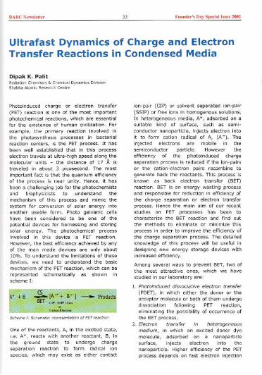
BARC New"e"" 33 Fouod,,', D,y Sped,' b,ue 2002
Ultrafast Dynamics of Charge and ElectronTransfer Reactions in Condensed Media
Dipak K. Palit",diolio' Chemi,t", & Chem,ce' Dyoomie< D'vi""Bhobh, Atomic "","ceh Ceotee
Photoinduced charge or electron transfer(PET) reaction is one of the most importantphotochemical reactions, which are essentialfor the existence of human civilization. Forexample, the primary reaction involved inthe photosynthesis processes in bacterialreaction centers, is the PET process. It hasbeen well established that in this processelectron travels at ultra-high speed along themolecularunits - the distance of 17 10. istraveled in about 3 picosecond. The mostimportant fact is that the quantum efficiencyof the process is near unity. Hence, it hasbeen a challenging job for the photochemistsand biophysicists to understand themechanism of this process and mimic thesystem for conversion of solar energy intoanother usable form. Photo galvanic cellshave been considered to be one of thepotential devices for harnessing and storingsolar energy. The photochemical processinvolved in this device is PET reaction.However, the best efficiency achieved by anyof the man made devices are only about10%. To understand the limitations of thesedevices, we need to understand the basicmechanism of the PETreaction, which can berepresented schematically as shown inscheme I:
Scheme I: Schematic repre,en"tion of PET reaction
One of the reactants, A, in the excited state,i.e. A*, reacts with another reactant, B, inthe ground state to undergo chargeseparation reaction to form radical ionspecies; which may exist as either contact
ion-pair (CIP) or solvent separated ion-pair(SSIP) or free ions in homogenous solutions.In heterogeneous media, A*, adsorbed on asuitable kind of surface, such as semi-conductor nanoparticle, injects electron intoit to form cation radical of A, (A'*). Theinjected electrons are mobile in thesemiconductor particle. However theefficiency of the photoinduced chargeseparation process is reduced if the ion-pairsor the cation-electron pairs recombine togenerate back the reactants. This process isknown as back electron transfer (BET)reaction. BET is an energy wasting processand responsible for reduction in efficiency ofthe charge separation or electron transferprocess. Hence the main aim of our recentstudies on PET processes has been tocharacterize the BET reaction and find outthe methods to eliminate or minimize thisprocess in order to improve the efficiency ofthe charge separation process. The detailedknowledge of this process will be useful indesigning new energy storage devices withincreased efficiency.
Among several ways to prevent BET, two ofthe most attractive ones, which we havestudied in our laboratory are:
1. Photoinduced dissociative electron transfer(POET), in which either the donor or theacceptor molecule or both of them undergodissociation following PET reaction,eliminating the possibility of occurrence ofthe BETprocess.
2. Electron transfer in heterogeneousmedium, in which an excited donor dyemolecule, adsorbed on a nanoparticlesurface, injects electron into thenanoparticle. Higher efficiency of the PETprocess depends on fast electron injection

BARC New,lett" 34 Found,,'s Day Spedall,,", 2002
and slow recombination between the cationand the injected electron.
We will discuss briefly about the principle ofthese methods taking the chemical systemsstudied in our laboratory as the models.
Recently large size electron donor-acceptor(EDA) molecules have shown promisingapplications in optical memory devices,optical sensors and optical switches. Theapplicability of an EDA molecule for aparticular purpose depends on how goodcontrol one has on the forward and the
backward charge transfer reactions. In thecase of a memory device, the forward andbackward charge transfer reactions can beused for storing in and reading out the data,and in optical switches, for switching on andswitching off, respectively. For thesepurposes, a suitable molecule, in which thedonor and the acceptor are widely separatedbut linked via a long molecular bridge, isdesigned and synthesized to control both theprocesses. However, the problems with theoptical devices made from such large EDAmolecules are evident from the fact that
following optical excitation, such a large sizemolecule in condensed phase (in solid orliquid solution medium) undergoes anumerous number ofintra and intermolecularprocesses, which areassociated or competingwith the intramolecular
charge or electrontransfer process. Amongthem three are the most
important ones:vibrational cooling, thesolvation of the excitedstate and theconformational relax-ation or isomerization.
All of the said processestake place in pica andsubpicosecond timedomain and can be
followed by probing therelaxation dynamics ofthe electronically excitedmolecules in condensed
phase using ultrafast transient absorptionspectroscopic techniques. Informationregarding these processes should help indesigning better and more efficient devices.
Experimental
Over the years, we have developed theultrafast transient absorption spectrometers,which have provided us the capability ofinvestigating the characteristics of thetransient intermediate species produced inphotoinduced chemical processes with picaand femtosecond time resolution. These
facilities, which are unique in India till today,has been proved to be work-horses in thestudy of dynamics of photochemicalreactions to unravel the intricacies of the
mechanistic details of them. Figure 1 showsthe block-diagram of our femtosecond laserkinetic absorption spectrometer, which hasbeen indigenously developed in thislaboratory. The working principle of thepicosecond absorption spectrometer is thesame as that of the femtosecondspectrometer, but the laser system used inthe later is a commercially available active-passive mode-locked Nd:YAG laser fromContinuum, USA.
CPM Laser: Colliding pulsed mode-locked dye laser; MMirror; G : Gratting; BS : Beam Splitter; L : Lens; SH :Sample Holder; SA : Saturable Absorber; CG : ContinuumGeneration; IF : Interference Filter; T : Beam Block; PDPhoto Diode Detector; P : 0{4 Plate; LSU : LaserSynchronisation Unit
Fig. 1, Block dlawam of the fem",eond laoec kinetic ab,orption 'peamme",.
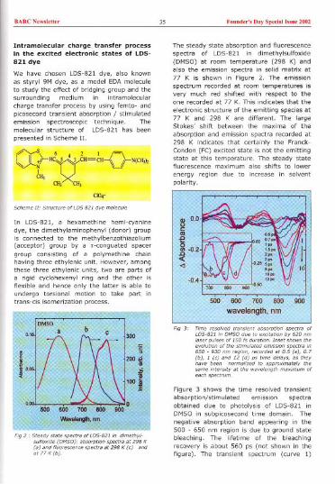
BARCN,wsl,"" 35 Found,,', Day Sp,dal Issn' 2002
Intramolecular charge transfer processin the excited electronic states of LDS-821 dye
We have chosen LDS-82I dye, also knownas styryl 9M dye, as a model EDAmoleculeto study the effect of brid9ing group and thesurrounding medium in intramolecularcharge transfer process by using femto- andpicosecond transient absorption / stimulatedemission spectroscopic technique. Themolecular structure of LDS-821 has beenpresented in Scheme II.
f"yS 6 2 1
-0-~tHC~CH=CH '" ;! N(CH,"
CH) ",X..CH) CH,
CI04-
SCheme III Sfeuauce of LOS 821 dye molecule
In LDS-821, a hexamethine hemi-cyanine
dye, the dlmethylaminophenyl (donor) groupis connected to the methylbenzothiazolium(acceptor) group by a IT-conguated spacer
group consisting of a polymethine chainhaving three ethylenic unit. However, amongthese three ethylenic units, two are parts ofa rigid cyclohexenyl ring and the other is
flexible and hence only the latter is able toundergo torsional motion to take part intrans-cis isomerization process.
The steady state absorption and ftuorescence
spectra of LDS-821 in dimethylsulfoxide(DMSO) at room temperature (298 K) andalso the emission spectra in solid matrix at
77 K is shown in Figure 2. The emissionspectrum recorded at room temperatures isvery much red shifted with respect to theone recorded at 77 K. This indicates that the
electronic structure of the emitting species at77 K and 298 K are different. The largeStokes' shift between the maxima of the
absorption and emisSion spectra recorded at298 K indicates that certainly the Franck-Condon (FC) excited state is not the emittingstate at this temperature. The steady statefluorescence maximum also shifts to lower
energy region due to increase in solventpolarity.
Figure 3 shows the time resolved transientabsorption/stimulated emission spectraobtained due to photolysis of LDS-821 inDMSO in subpicosecond time domain. Thenegative absorption band appearing in the500 - 650 nm region is due to ground statebleaching. The lifetime of the bleachingrecovery is about 560 ps (not shown in thefigure). The transient spectrum (curve 1)

BARC New,lott" 36 Found,,', Day Spedal "me 2002
recorded at 0.5 ps after the pump laserpulse, shows a weak stimulated emissionband in the 650 - 800 nm region with amaximum at ca 700 nm. With increase intime delay, this emission band disappearswith a concomitant development of apositive absorption band in the same regionas well as another emission band in the redside of the former (i.e. in the region 800 -900 nm). With increase in time delay thewavelength maximum of this new emissionband shifts gradually from ca 800 nm, as itstarts developing during ca 1 ps delay, to842 nm at 15 ps, when it is fully grown(curve 10). The temporal dynamics of thetransients monitored at 590, 730 and 850nm have been shown in Figure 4.
590 om
~ = 0.32 ps
730 om
~I- 300 fs~2=4ps
-6.04
0 5 10 15
time, ps
Fig 4 The e'olution of the tconsientstimuleted emission due to
of LOS'521 in OMSO.
The excited state dynamics of LDS-821 havebeen monitored in a few other solvents. Thegross features of the time-resolved transientabsorption characteristics are more or lesssimilar in other solvents as those describedin case of ACN. We observe the gradual shiftof the maximum of the time resolvedstimulated emission band (which is popularlyknown as the dynamic Stokes' shift), only inpolar solvents, but not in relatively less polar
chloroform solution. Hence, the growth ofthe emission band, which is accompanied bythe dynamics Stokes' shift, in 800 - 850 nmregime, cou:d be assigned to the formationof an intramolecular charge transfer (ICT)state and its simultaneous solvation.
Fig S , Potentiel eneegy su;feee depicting the two.stetetwo.mode model foe the ,elexetion of LOS'S2lmolecule in the excited singlet stete
The time resolved spectra as well as thetemporal dynamics of the stimulatedemission monitored at different wavelengths(Figures 3 and 4) mainly reveal the featuresof two-state two-mode kinetic process -local excited (LE) state to the twistedintramolecular charge transfer (TICT).state(Figure 5). For short wavelength detection,e.g. at 730 nm, we observe the S, staterelaxation in the region close to the FC point.The observation of a short (51 ps) rise timeas well as very fast spectral evolution in thishigher energy spectral regime (700 - 800nm), are the signatures of the transientspecies evolving along the skeletaldeformation coordinate in the 'valley-like'region to attain the metastable untwistedintermediate conformation, called the LEstate. This process is followed by torsoinalmotion about the free double bond (C, = C,)accompanied by the intramolecular chargetransfer to form the TICTstate.
Dye sensitized photo-inducedelectron injection into TiO2semiconductor nanoparticle
Interfacial electron transfer betweenmolecular adsorbate and semiconductornanoparticle is an intense area of research
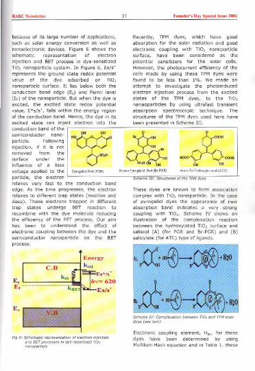
BARC Newde"" 37 Fouud,,'s Day Special Issue 2002
because of Its large number of applications,such as solar energy conversion as well asnanoelectronic devices. Figure 6 shows theschematic representation of electronInjection and BET process In dye-sensitizedTIO, nanopartlcle system. In Figure 6, Es/s'represents the ground state redox potentialvalue of the dye adsorbed on TiO,nanopartlcle surface. It lies below both theconductionband edge (Ee)and Fermilevel(Ee)of the nanopartlcle.Butwhenthe dye IsexCIted, the excited state redox potentialvalue, E*s/s', falls within the energy regionof the conduction band. Hence, the dye In Itsexcited state can Inject electron into theconduction band of thesemiconductor nano-particle. FollowingInjection, If it Is notremoved from thesurface under theInfluence of a bias
voltage applied to the I PY'ogillclR.d(PGR)particle, the electronrelaxes very fast to the conduction bandedge. As the time progresses, the electronrelaxes to different trap states (swallow anddeep). These electrons trapped in differenttrap states undergo BET reaction torecombine with the dye molecule reducingthe efficiency of the PET process. Our aimhas been to understand the effect ofelectronic coupling between the dye and thesemiconductor nanoparticle on the BETprocess.
H
~I H
o,H
"I
Ev
EelE,
Fig 6'
Recently, TPM dyes, which have goodabsorption for the solar radiation and goodelectronic coupling with TIO, nanopartlclesurface, have been considered as thepotential sensitizers for the solar cells.However, the photocurrent efficiency of thecells made by using these TPM dyes werefound to be less than 1%. We made anattempt to Investigate the photoinducedelectron Injection process from the excitedstates of the TPM dyes, to the TIO,nanaoparticles by using ultrafast transientabsorption spectroscopic technique. Thestructures of the TPM dyes used here havebeen presented in Scheme III.
~ H
I I
1COOK
H OH
A=nT,iC.b~;1i. ",'(ATe)B,om'PY'",",1 R,d(B,PGR)
Scheme III' St;uctu;e> of the TPM dye>
These dyes are known to form association
complex with TIO, nanoparticle. In the caseof pyrogallol dyes the appearance of newabsorption band indicates a very strongcoupling with TIO,. Scheme IV shows anillustration of the complexation reactionbetween the hydroxylated TiO, surface andcatecol (A) (for PGR and Br-PGR) and (B)
salicylate (for ATC) type of ligands.
Electronic coupling element, H", for thesedyes have been determined by usingMulliken-Hash equation and In Table 1, these

BARC Newsletter 38 Founder's nay Special Issue 2002
have been compared with those of N3 andother dyes, with which the best efficiency forsolar energy conversion has been achieved.
Table 1
...
-::;...
....
Olio m 1io litWawIMgth 1II1II)
Fig 7' T"nsient abwption spe",a of PGR sensitizedno, nanoparticle in wate, at 0, 5 and 10 psaftee excitation at 620 nm lase, pulses of 150 fsdu"Uon. The feawces of each spertrom consistsof a bleach ., 515 -620 nm and the abs",pUonpeak due to the PGR cation "dical at 690 nmand a broad absomlion band in the speetcalcegion 750 -900 nm due to the injected electroninto thesemicondu"o, particle.
Our studies on ultrafast dynamics ofphotoinduced electron transfer processes ofthe three strongly coupled TPM dyesadsorbed on TiO, nanoparticle suoface haveestablished that electron injection from theexcited dye to the nanoparticie takes placefaster than 200 femtosecond. Appearance ofboth the bleaching as well as cation radicalabsorption are faster than our instrumentalresponse function (Figures 7 and 8). Alsoboth the bleach recovery and cation decayfollow similar kind of dynamics, which are
A.cation decoy, 690 DID
.'" 2ODamelps)
... ....
Fig 8 , Cation decay and bleach cecove"! in PGR-TiO,system following photo",c""ion by 620 nmiase, pulse of 150 fs du"tion.
...
nonexponential, in the case of the pyrogalloldyes. These temporal profiles show thatmore than 70% of bleach has recovered or
cation decay has taken place within 10picosecond time scale. However, in case ofATC sensitized TiO, system, in which thecoupling of the dye with the semiconductorparticle is relatively weaker, the bleachrecovery is much slower than those of thepyrogallol dyes (figure 9). Both the bleachrecovery and the cation radical decayrepresent the BET reaction. BET reaction hasbeen seen to be continued up to nanosecondand microsecond time scale. However the
BET reaction Is much slower for the weaklycoupling dye ensuring better efficiency forthe charge separation process.
"[:=':'~720:,:;"m......t.~
....,. ..
"'0(").... ...
WawIengIh Inm)
Fig 9 , T"nsient absomUon speetea of Arc sensilizedTiO, nanoparticle in watee at 0, 33, 132, 330,660 and 1320 ps after photoexc"ation. (Inset,the bleach cecove,,! kineticsI
Dye Molecule H" em"
Pyrogallol red (PGR) 6.8 x 10³Bromo-pyrogallol red (Br- 8.2 x 10³PGR) 4 x 10'Aurin triboxylic acid (ATe) 2 x to'Coumarin-343 1.3 x 10'Ru(I!!)L,(NCS), (N, Dye)
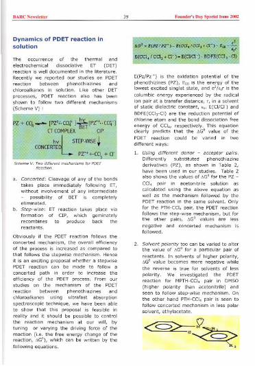
BARC N,ws!,"« 39 Found,,'s Day Sp,da! bsu, 2002
Dynamics of PDET reaction insolution
The occurrence of the thermal and
electrochemical dissociative ET (OET)reaction is well documented in the literature.Recently we reported our studies on POETreaction between phenothiazines andchloroalkanes in solution. Like other OETprocesses, POET reaction also has beenshown to follow two different mechanisms(Scheme V) :
Pi§'oCCIt Ji'-[PZo+..CCI;'-['cOMPLEX ET ClP
,
~.
'
.,..
V
L$TEP-W'$E+'NCERT£D
~,~~" , pzo++CCL + cr
Scheme V, Two ""tecent mechanisms toe POETReaction.
a. Concerted: Cleavage of any of the bondstakes place immediately following ET,without involvement of any intermediate- possibility of BET is completelyeliminated.
b. Step-wise: ET reaction takes place viaformation of CIP, which geminatelyrecombines to produce back thereactants.
Obviously if the POET reaction follows theconcerted mechanism, the overall efficiencyof the process is increased as compared tothat follows the stepwise mechanism. Henceit is an exciting proposal whether a stepwisePDET reaction can be made to follow a
concerted path in order to increase theefficiency of the PDET process. From ourstudies on the mechanism of the PDET
reaction between phenothiazines andchloroalkanes using ultrafast absorptionspectroscopic technique, we have been ableto show that this proposal is feasible inreality and it should be possible to controlthe reaction mechanism at our will, bytuning or varying the driving force of thereaction (i.e. the free energy change of thereaction, ~Go), which can be written by thefollowing equations.
E(Pz/Pz") is the oxidation potential of thephenothizines (PZ), Eoo is the energy of thelowest excited singlet state, and e'lcor is thecolumbic energy experienced by the radicalion pair at a transfer distance, r, in a solventof static dielectric constant, cO' E(CI/CI') and
BDFE(CCI,-CI) are the reduction potential ofchlorine atom and the bond dissociation free
energy of CCI" respectively. This equationclearly predicts that the ~Go value of thePDET reaction could be varied in twodifferent ways:
1. Using different donor - acceptor pairs.Differently substituted phenothiazinederivatives (PZ), as shown in Table 2,have been used in our studies. Table 2also shows the values of AGo for the PZ -
CCI, pair in acetonitrile solution ascalculated using the above equation aswell as the mechanism followed by thePDET reaction in the same solvent. Onlyfor the PTH-CCI, pair, the PDET reactionfollows the step-wise mechanism, but forthe other pairs, ~Go values are lessnegative and concerted mechanism isfollowed.
2. Solvent polarity too can be varied to alterthe value of AGo for a particular pair of
reactants. In solvents of higher polarity,AGo value becomes more negative whilethe reverse is true for solvents of less
polarity. We investigated the PDETreaction for MPTH-CCI, pair in OMSO(higher polarity than acetonitrile) andseen to follow step-wise mechanism. Onthe other hand PTH-CCI, pair is seen tofollow concerted mechanism in less polarsolvent, ethylacetate.
(/
~?6c
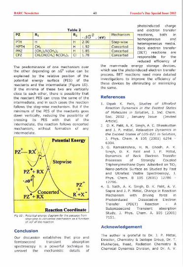
BARC Newsl"'" 40 Found,,', Day Spedallssue 2002
Table 2photoinduced chargeand electron transferreactions, both inhomogeneous andheterogeneous media.Back electron transfer(BET) reactions areresponsible for thereduced efficiency of
the man-made energy storage devices,which use the photoinduced electron transferprocess. BET reactions need more detailedinvestigations to improve the efficiency ofthese devices by eliminating or minimizingthe same.
The predominance of one mechanism overthe other depending on ~Go value can beexplained by the relative position of thepotential energy surface (PES) of thereactants and the intermediate (Figure 10).If the minima of these two are verticallyclose to each other, there is possibility thatthe reactant PES can cross the same of theintermediate, and in such cases the reactionfollows the step-wise mechanism. But if theminimum of the PES of the reactants goesdown vertically, reducing the possibility ofcrossing its PES with that of theintermediate, the reaction follows concertedmechanism, without formation of anyintermediate.
Reaction CoordinateFig 10,
Conclusion
Our discussion establishes that pico and
femtosecond transient absorptionspectroscopy is a powerful technique tounravel the mechanistic details of
References
1. Dipak K. Palit, Studies of Ultrafast
Reaction Dynamics in the Excited Statesof Molecules in Solution, J. Ind. Chem.Soc. 2002 , January Issue (InvitedArticle).
2 D. K. Pal it, A. K. Singh, A. C. Bhasikuttanand J. P. mittal, Relaxation Dynamics inthe Excited States of LDS-821 in Solution,J. Phys. Chem. A 105 (2001) 6294 -6304.
3. G. Ramakrishna, H. N. Ghosh, A. K.Singh, D. K. Palit and J. P. Mittal,Dynamics of Back Electron TransferProcesses of Strongly CoupledTriphenylmethane Dyes Adsorbed on TiO,Nano-particle Surface as Studied by Fastand Ultrafast Visible Spectroscopy, J.Phys. Chem. B 105 (2001) 1278612796.
4. S. Nath, A. K. Singh, D. K. Palit, A. V.Sapre and J. P. Mittal, Change in ReactionMechanism with driving force InPhotoinduced Dissociative Electron
Transfer (PDET) Reaction ASubpicosecond Transient absorption
Study, J. Phys. Chem. A. 105 (2001)7151.
Acknowledgement
The author is grateful to Dr. J. P. Mittal,Director, Chemistry & Isotope Group, Dr. T.Mukherjee, Head, Radiation Chemistry &Chemical Dynamics Division, and Dr. A. V.
PZ R, R,-LlGO, (eV)
Mechanism
PTH H H 2.00 Step-wiseMPTH CH3 H 1.92 ConcertedPMZ CH, 3N CHe , H 1.85 ConcertedCPZ CH,CH(CH,)N(CH,h CI 1.78 Concerted
BARC NewsleU" 41 Found,,', Day Spedal '"ue 2002
Sapre, Head, Chemical Dynamics Section, fortheir constant encouragement and supportthroughout his career. The author alsoacknowledges the active scientific
contributions from his co-workers and co-authors of the papers mentioned in thereference section. Without their help it wouldnot have been possible to write this article.
Dr Dipak Kumar Palit was awarded the "Bronze Medal of 200i" by the ChemicalResearch Society of india in its Annaal Conference held at Pune during February28- March2,2002.Thearticleis writtenon thelecturedeliveredbythe authorinthis conference.
About the author ...
Or Dipak Kumar Pant joined the Cheml,tcy BARC, oftec completion of the one-yeacoclentotlon couc« (26" batch) of BARC Tcoining Aftec obtoining his Ph. D. degcee fcomBomboy Unlve;>ltyin 1989, he wos owocded "BOYSCASTFellowship" of OST foc his post-doctocolwock on ultcafastspectcoscoPYin the Unlve;>lIyof Pennsylvonlo, USA.His cuccent ceseacch Inteceotisto study chemical coactiondynamics in conden«d phose using ultcafast losecs and accelecatocs.

BARC New,'etter 42 Founder', Day Special [..ne 2002
Preparation, Optim ization I Characterizationand Ion-Exchange Behaviour of VeIl)FormulationsJ Manjanna and G VenkateswaranApplied Chemist", DivisionBhabha Atomic Research Centre
Abstract
The low oxidation state metal ion, V,. being a strong reducing agent can be formulated!complexed with suitable chelating agents to obtain a significant dissolution (reductive) of ironoxides, commonly found on the primary system surfaces (iron base alloys) of water-coolednuclear reactors. The relative strength of the complexes of 11" (as formate) with differentchelating agents, L such as picoHnic acid, EDTA and citric acid is studied by measurements ofredox potential and UV-Visible spectra, The decay kinetIcs of the reduction of water by 1'(11)-picollnate i.e. V" to va' conversion under deaerated condition was estimated using redoxpotential values and decay was found to follow two stages of first order kinetics with a fasterinitialstage (k, =3.45 x 10'3 min") and a slower second stage (k, =3.84 x 10~ min"). Thecation and anion exchange resin behaviour of the complexes! formulations in their differentoxidation states with their derived species Is reported and the V(III)-picolinate is shown to existas an anionic species in formate medium. The use of V(II)-EDTA and V(II)-citrate for dissolutionhas an advantage as their oxidation to V(III) stage at concentrations > 7m'" has not resulted inany precipitation! crystallization unHke in the case of V(II)-picoHnate.
Introduction
The chemical decontamination of primarycoolant circuit in water-cooled nuclear powerreactors involves the dissolution of corrosionfilms (Ni, Cr-substituted as well as simpleiron oxides) accumulated on the structuralsurfacesH, The Cr-containing iron oxides arenot easily amenable for dissolution inconventional organic acid based formulationslike citric acid-EDTA-ascorbic acid (CEA)mixture"'. However, low oxidation statemetal Ions (LOMI) such as V" and Cr" inpresence of suitable chelatlng agents areknown to be very strong reducing agents(rapid kinetics) towards the dissolution ofsuch oxide matrices"'. Normally VIII) basedLOMIformulations Involving V(II)-picolinateis employed for such purposes'. Use of VIII)plcolinate complex Is limited to concentrationlevels below 7 mM. Above this concentrationlevel, VIllI) picolinate (which Is generatedeither during reductive dissolution ofcorrosion films accumulated on structuralsurfaces or some times by air oxidation due
to system air leaks) precipitates!crystallizesout. The use of EDTA and citric acid ascomplexing agents can overcome suchsolubility problems. The electrochemicalmethod of preparing VeIl) enables thegeneration of composition specificformulations, which is an importantconsideration towards base materialcompatibility aspects in real systemapplications. The relative stability ofelectrochemically prepared V(II)-picolinate,V(II)-EDTA and V(II)-citrate complexeslformulations as derived from the redox andUV-Visiblespectra are reported in this paper.The behaviour of these complexes in theirdifferent oxidation states on the conventionalion-exchange resin is studied, and thederived species getting sorbed is reported.The detailed studies on the dissolution of Cr-substituted oxides in these formulations arepublished elesewhere'.
Experimental Set Up
ElectrochemIcal Assembly: A flatbottomed glass vessel of 500 mL capacity

BARCNew,'eU" 43 Foond,r', Day Spedall,""e 2002
was used for preparing V" (as formate).Fig. 1 shows the electrode compartmentsand its power supply unit as well asarrangement for cathode/solution potentialmeasurements. The cylindrical pt gauze wasmade as anode, and Hg pool served ascathode. A sintered glass disc separated theanode and cathode compartments. Asaturated calomel electrode (SCE) was usedas reference electrode.
Fig.
5. SCE7.
6.
Table 1: The optimized parameters for theelectrochemical generation of VeIl) formate
Electrolysis: The electrolysis was carriedout after charging required amounts ofcatholyte and anolyte. In cathode compart-ment a known amount of aqueous NaVO, informic acid media (pH ~2.8) was placed,while in the anode compartment only formic
acid of appropriate concentration was taken.Before starting the electrolysis the solutions(both anolyte and catholyte) were kept fordeoxygenating ca.~30 min using high purityN2 gas (scrubbed through V" trap generatedby Zn-amalgum in HCI) and N, bubbling wascontinued throughout the electrolysis. Theconcentration of formic acid (anolyte), cell-current, cell-voltage and time required forcompletion of electrolysis (Table 1) to obtainV'. (as V"(HCOO),) in the concentrationrange of 4 44 mM were optimized/standardized from the initial experiments.The optimization was done by number ofinitial trial experiments based on thestoichiometric amount of formate ionsrequired as well as the reduction potentialsreported in the literature' for the reductionof vanadium species.
Estimation of V(II)-formate : The electro-generation of V" species was confirmed byonline redox potential (~ -0.580V vis. SCE)measurements. During electrolysis, thesolution was kept circulating from the vesselthrough a burette using a peristaltic pump.This arrangement helped in titrating thesolution periodically against standard KMnO,solution to estimate the extent of V"generation. The oxidation of V'. bypermanganate can be represented as,
5V'. + 3MnO, + 24W (10% H,SO,) -7
5Vs. + 3Mn" + 12H,O
The electrolysis proceeded with theaccompanying colour changes viz.yellow, blue, green and purple forV(V), V(IV), V(III) and VeIl)respectively during electrolysis.
Estimation free formic acid: Thetotal formic acid content was estimated
at the end of the electrolysis bypassing the sample through the strongacid cation exchange resin. The eluate
was titrated against standard NaOH solutionusing phenolphthalein indicator. The freeformic acid was calculated from the totalformic acid by subtracting two times the V"concentration and the sodium concentrationfrom the initial sodium metavenadate usedfor the preparation of V,. (Table 2).
Catholyte, Anolyte, Cell Cell Time
NaVO, pH HCOOH Current Voltage (min)
2.8
4 mM 2.0 M 80 mA 40 V 60
11 mM 2.6 M 60
22 mM 3.5 M 70
44 mM 4.0 M gO

BARCN,w,l,"" 44 Found,,', D,y Sp,dal Issu, 2002
Table 2: Composition of V(II) formulations (in mM)containing stoichiometric amount of l for thedissolution of 20 at.% csh/csm'
Formulation/ Complexation of V"species: After confirmation and estimationof V'+ species, the electrolysis was stoppedand the Hg (cathode) was removed carefully(through the outlet provided with the flask).The V'+(as formate) thus generated wasthen made to complex with differentchelating agents viz. picolinic acid (HoPic),EDTA (disodium salt, Na,EDTA) and citricacid (CoH,O,). The EDTAand citric acid wereadded directly in to the cell containing VeIl)formate. However, the picolinicacid requiredto complex with V'+ was neutralized (inorder to provide the ligand in readilycomplexable form) with NaOH separately ina deaerated aqueous medium before itsaddition. In all the cases, stochiometricallyexcess (w.r.t v'+) amounts of chelatingagent, L viz. H3Pic, Na,EDTA and CoH,O,were added. Table. 3 shows the compositionof VeIl) based formulations which have beenemployed in the dissolution studies of Cr-substituted iron oxidess. The amount ofchelating agent provided in each case isstoichiometrically equivalent to that requiredfor complexation with V" species as well asFe and Cr from the oxide ca. 20 metalatom% Cr-substituted hematite/magnetite(as a typical case).
Dissolution behaviour: Fig. 2 shows thetypical dissolution profiles of Cr-substitutedhematite/magnetite in V(II)-EDTA and CEA(citric acid-EDTA-ascorbic acid) formulations.The details of experiment, and the
determination of dissolution ratecoefficients using general kineticequation applicable for polydispersedparticles are reported3.'.'. It isobserved that the Cr substitution inhexagonal lattice (a-Fe,O,) hashindered the dissolution to a greaterextent than that observed when Cr issubstituted in cubic lattice (FeoO,).Using CEA, the complete dissolutionof simple iron oxides viz., a-Fe,O,and upto 10% Cr-substitutedmagnetite can be obtained to thereductive mechanism of internallygenerated (during the course ofdissolution) Fe(II)-EDTA. However,
when Cr is substituted to the extent of >10at%, there was no dissolutionS even onemploying higher concentrations of CEA. Asshown in Fig.2, vanadous formulation, V(II)-EDTA has resulted higher dissolution whencompared to CEA, and there is a higherdissolution in the case of csm. Thisobservation documents the advantage ofemploying vanadous formulations overconventional formulations like CEA Indissolving Cr-substituted iron oxidesencountered on the structural surfaces ofwater-cooled nuclear reactors.
1 eo'E
i'i "
00 130 200 20° "0 '00 'DC
Dissolution time (min)
Fig 2.. Tvpical d'ssolutioo pcofiles obtamed for csh/ csm10 VE ond CEA formulatioo. csh/csm.. Cr-substituted hematite/magoetite; VE.. V(II)-EDTAformulaVon, 22 mM; CEA.' 11 mM citric acid +44 mM Na,EDTA + 44 mM ascorbic acid (pH 2.8)mixture
[V"- [Pic] [EDTA] [Cit] [HCOOformate] pH pH pH H]
pH 4.0,,0.3 3.6,,0.3 2.6"0.33.0+0.3
4 93 31 31 811 114 38 38 3922 147 49 49 43
equivalent to 22 mM iron and 5.5 mM Cr (fromFe",CrQAO3/Fe"CrosO,) in 200 mL formulation (seeref 5).

BARC New,leU" 45 Found,,', Day Spedal bme 2002
Ion-exchange behaviour: During thisparticular study, the L was added equivalentto the stoichiometric complexation of V2'alone and no extra L (free L) was provided.The V(II)-L ( formic acid, picolinicacid, EDTAand citric acid) were passed through strongacid cation and ! or anion exchane resin(polystyrene based gel type resin). The resinbed was regenerated (by 5%H,Sa, or NaaH)freshly and deoxygenated by circulatingdeaerated water before passing the V(II)-L.For this purpose, a closed loop was setupfrom electrolyticcell and resin column withthe help of peristaltic pump. Uniform flowrate, 5mL!min was maintainedin eachcase.The oxidized forms of V(II)-L viz., V(III)!(IV)! (V)-L were obtained on controlled airoxidation of V(II)-L for which theconversions were monitored by redoxpotential measurements.
Results and Discussions
Electrochemical Generation of v>+ : The
vanadous ion, V" was prepared as VeIl)formate by the electrochemical reductionover the surface of Hg, using deoxygenatedaqueous solution containing requiredamounts of sodium meta vanadate (NaVa,)and formic acid at pH 2.8. The cellparameters such as current, voltage andduration of electrolysis are shown in Table 1.During electrolysis, the step-wise reductionof va, + to V'+ can be represented"" by thefollowing equations (V versus SHE).
NaVa, > Na+ + va,- on ionization
va, +2H' <---> va2 ++H,a chemical process
va! +2H' +e- <--->va" +H,a, Eo = 1.00V..(1)
va" directly goesto V,. irreversiblyas
va" + 2H' + 2e---> v,. + H2a ...(2)
Also,v,. thus generated reduces va" to v"easily and in the process gets oxidized to V3'as
V2++ va'+ + 2H' --> V,. + V,. + H,a ...(3)
Then V,. from Eq. (3) was reducedtoV,. as
V'+ + e- <---> V'+ , Eo = -0.255V
Due to H' consumption during electrolysis,the initial pH (2.8) of catholyte wasincreased slightly to pH 3.0 at the end ofelectrolysis. In anode compartment thedecomposition of water resulted in theliberation of a, during electrolysis and inorder to improve the conductivity of thesolution, an appropriate amount of formicacid was placed. Whenever the formic acidwas not sufficient (during the initialexperiments), a black precipitate of vanadicoxide, which is the hydrolysis product ofvanadium was noticed. Monitoring thesolution potential on pt electrode helped infollowing the reduction process duringelectrolysis. The yellowish orange va! turnsto sky blue colour of va" which before goingto the purplish violet colour of V,. goesthrough a dark blackish green stage showingthe formation of V" also in the solutionaccording to the Eq. (3). The variation ofcathode potential and solution potentialduring the time of electrolysis in a typicalcase of 11 mM is shown in Fig. 3.
~
,,~4 .ib.~ ~
.00 \, 0 s
eo l "0'0 0 ]
o~...o\:0 Io"'o-o-o-o~:::::~=~=~= ..00 a
" " 00El""oly,iotim,(min)
Fig. 3. w!tht;meV,. (a,
metmnadote in
...(4)
The electrolytic generation of V(II)-picolinateand its application in the decontamination ofBWR surfaces has been presented previouslyfrom our laboratory". During the same
study, E'!2 was found to be -1.32V (vs. SCE)and the potential corresponding to thelimiting diffusion current is -1.4 to -1.6Vusing DC polarogram. In the present casealso a cell of ~40V yielded a cathodepotential of -1.55V in the later stage ofelectrolysis. Also, the V2+ could be generated
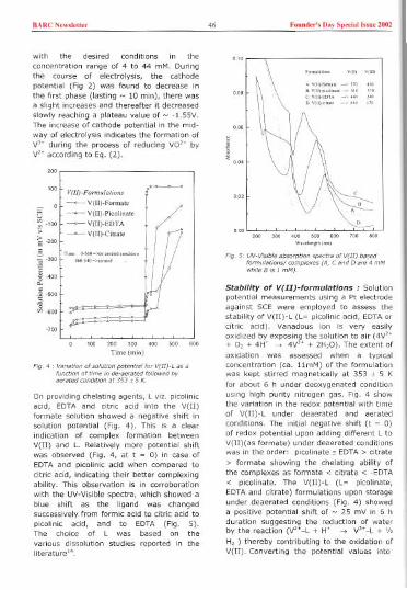
BARC Now,',"" 46 Foond,,', Doy Sp,do' h.u, 2002
with the desired conditions in the
concentration range of 4 to 44 mM. Duringthe course of electrolysis, the cathodepotential (Fig 2) was found to decrease inthe first phase(lasting ~ 10 min), there wasa slight increases and thereafter it decreasedslowly reaching a plateau value of ~ -1.55V.The increase of cathode potential in the mid-way of electrolysis indicates the formation of
V" during the process of reducing va" byV,. according to Eq. (2).
100 V(II)-Fa"""Za",",, l-'-~'~ 0 ~-V(II)-Fonm" Ie: -- V(II)-Pi,alin",! /';;-100 -.-V(II)-EDTA
0
'
; ~ V(II)-Citt'" 'I_
1'
E .200 It300 ..mo
,
"""O""'"'"" 1/
1/~ .400 ! I
isoo U
~600 :==8=-f;;'i:'===~
200 300 400
Time (mio)
500
Fig 4
On providing chelatingagents, L viz. picolinicacid, EDTA and citric acid into the VIII)formate solution showed a negative shift insolution potential (Fig. 4), This is a clearindication of complex formation betweenVeIl) and L. Relatively more potential shiftwas observed (Fig. 4, at t = 0) in case ofEDTA and picolinic acid when compared tocitric acid, indicating their better complexingability. This observation is in corroborationwith the UV-Visible spectra, which showed ablue shift as the ligand was changedsuccessively from formic acid to citric acid to
picolinic acid, and to EDTA (Fig. 5).The choice of L was based on thevarious dissolution studies reported in theliterature".
]<ON
Wm'm,o",om)
FIg, S'mM
while B 151
Stability of V(II)-formulations : Solutionpotential measurements using a Pt electrodeagainst SCE were employed to assess thestability of V(II)-L (L= picolinic acid, EDTA orcitric acid). Vanadous ion is very easilyoxidized by exposing the solution to air (4V"+ A, + 4W -+ 4V" + 2H,O). The extent of
oxidation was assessed when a typicalconcentration (ca. llmM) of the formulationwas kept stirred magnetically at 353 I 5 Kfor about 6 h under deoxygenated conditionusing high purity nitrogen gas. Fig, 4 showthe variation in the redox potential with timeof V(II)-L under deaerated and aeratedconditions, The initial negative shift (t = 0)of redox potential upon adding different L toV(II)(as formate) under deaerated conditionswas in the order: picolinate" EDTA > citrate
> formate showing the chelating ability ofthe complexes as formate < citrate < -EDTA< picolinate. The V(II)-L (L= picolinate,EDTA and citrate) formulations upon storageunder deaerated conditions (Fig. 4) showeda positive potential shift of ~ 25 mV in 6 hduration suggesting the reduction of waterby the reaction (V"-L + W -+ V"-L + 'hH, ) thereby contributing to the oxidation ofVIII). Converting the potential values into
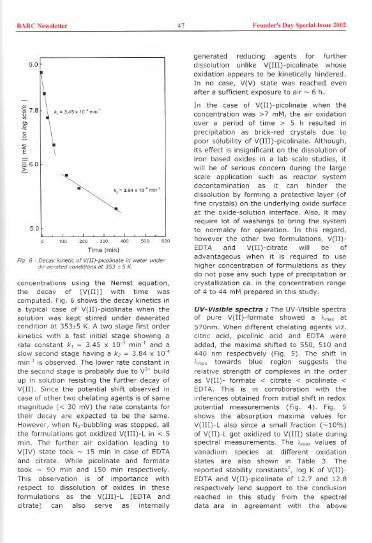
BARC N""lo"" 47 Foood,,', Day Spodal'"'"' 2002
9.0
k,' "5. 10' m;o'
0D
"E
S6.0G
'~""'0'm;o'
5.0
'00
Time (mln)
Fig, 6
concentrations using the Nernst equation,the decay of [V(II)] with time wascomputed. Fig. 6 shows the decay kinetics Ina typical case of V(II)-plcollnate when thesolution was kept stirred under deaeratedcondition at 353"5 K. A two stage first orderkinetics with a fast Initial stage showing arate constant k, ~ 3.45 X W' min" and aslow secondstage having a k, ~ 3.84 x 10'mln-; is observed. The lower rate constant In
the second stage Is probably due to V'. buildup In solution resisting the further decay ofV(II). Since the potential shift observed Incase of other two chelating agents Is of samemagnitude « 30 mV) the rate constants for
their decay are expected to be the same.However, when N,-bubbling was stopped, allthe formulations got oxidized V(III)-L In < 5min. The further air oxidation leading toV(IV) state took ~ 15 mln In caseof EDTAand citrate. While plcolinate and formatetook ~ 90 mln and 150 mln respectively.This observation Is of Importance withrespect to dissolution of oxides in theseformulations as the V(III)-L (EDTA andcitrate) can also serve as Internally
generated reducing agents for furtherdissolution unlike V(III)-picolinate whoseoxidation appears to be kinetically hindered.In no case, V(V) state was reached evenafter a sufficient exposure to air ~ 6 h.
In the case of V(II)-plcolinate when theconcentration was >7 mM, the air oxidationover a period of time> 5 h resulted Inprecipitation as brick-red crystals due topoor solubility of V(III)-picolinate. Although,its effect Is Insignificant on the dissolution ofIron based oxides In a lab scale studies, itwill be of serious concern during the largescale application such as reactor systemdecontamination as it can hinder the
dissolution by forming a protective layer (offine crystals) on the underlying oxide surfaceat the oxide-solution Interface. Also, it mayrequire lot of washings to bring the systemto normalcy for operation. In this regard,however the other two formulations, V(II)-EDTA and V(II)-citrate will be ofadvantageous when it Is required to usehigher concentration of formulations as theydo not pose any such type of precipitation orcrystallization ca, In the concentration rangeof 4 to 44 mM prepared In this study.
UV-Visibfe spectra: The UV-Vlslble spectraof pure V(II)-formate showed a )'m" at570nm, When different chelating agents vlz,citric acid, plcolinlc acid and EDTA wereadded, the maxima shifted to 550, 510 and440 nm respectively (Fig,S). The shift In
towards blue region suggests the
relative strength of complexes In the orderas V(II)- formate < citrate < plcolinate <EDTA, This Is In corroboration with theInferences obtained from Initial shift In redoxpotential measurements (Fig, 4), Fig,Sshows the absorption maxima values forV(III)-L also since a small fraction (~10%)of V(II)-L got oxidized to V(III) state duringspectral measurements, The "~m"~values of
vanadium species at different oxidationstates are also shown In Table 3. The
reported stability constants', log K of V(II)-EDTA and V(II)-plcolinate of 12,7 and 12,8respectively lend support to the conclusionreached in this study from the spectraldata are In agreement with the above
BARC Newsle"« 48 Founder's Day Spedal I"ue 2002
observations. Though, the stability constantvalue of V(II)-citrate is not available, andVO" -citrate is reported to have a log K of8.8, from the present study it is expectedthat citric acid forms relatively weakercomplex with VeIl).
Ion-exchange behaviour The
decontamination is generally followed by theremoval of all the chemical constituents of
the decontaminating formulations. Passingthe dissolved species (aqueous) throughcation andlor anion exchange resin normallydoes this exercise. The V" species afterreducing the ferric oxides (corrosionproducts) can go to higher oxidation state of+3 and +4 and some times to even +5 dueto the increase in dissolved oxygen contentin the system. Hence, the ion exchangebehaviour of these complexes of vanadium
with citric acid, EDTA and picolinic acidbecomes important when spentdecontamination solution is treated bysynthetic organic ion exchange resin as a
part of waste solidification. Thus in thisstudy, all these formulations at differentoxidation states of vanadium (higheroxidation states were obtained by air
oxidation of V'. formulations) were passedthrough strong cation and strong anionexchange resin independently. It was foundthat the anion resin picked up all thesespecies while the V", V3. and va'.excepting VO,' -citrate complexes weredissociating on the cation exchanger. The
fact that, the V(III)-plcollnate which isusually referred as V(pic), (neutral complex),gets sorbed on the anion exchanger showsthat it is existing as anionic complex informate medium and may be represented as[V(pich(HCOO),r. Existence of vanadiumspecies in different oxidation states withdifferent chelating agents and their sorptionbehaviour on the cationl anion exchanger isshown in Table 4. Thus the ion exchangebehaviour of VeIl) formulations is highlyencouraging for their application in nuclearreactors as a decontamination formulations.
Table 3: Absorption maxima, ).m.. (in nm) of the vanadous formulations at differentoxidation states
Table 4: Ion-exchange (IX) behaviour of vanadous based formulations and theiroxidized forms on polystyrene based strong acid cation and anion exchange resin
Chelating agent Vanadium species
VeIl) V(III) V(IV) V(V)
Formic acid 570 430 382 215
Picolinic acid 510 370 361 325
EDTA 440 240 244 232
Citric acid 550 370 242 230
Metal Likely metal ion species on the complexed form IX behaviourO.s ion with different chelatina agents
species Picalinic acid EDTA Citric acid cation anion
+2 V" [Vh(pic),] [V" -EDTAJ" [V"-H"cit]' , ,+3 V3. [V3.(pich(HCOO)'J [V3.-EDTAr [V3.- H"citr ' ,+4 va'. [VO"(pic)'J [VO"EDTA]" [VO"-H"cit]'" ,+5 va: [VO,.(plc),J" [Va, .EDTA]3' [VO:-H"cit]3 x ,Here ( ) and (x) symbol Indicates the removal and non-removal by resin respectivelya,s: oxidation state

BARC Now,kU" 49 Foood,,', Day Spo"ol h.uo 2002
Conclusions
The relative complexing ability of chelatingagents with V"(as formate) underdeoxygenated condition follows the order canbe shown as V(II)-formate < V(II)-citrate <V(II)-picolinate ~ V(II)-EDTA. Their stabilityin aqueous medium under deoxygenatedcondition followed two-stage decay kinetics.The Ion exchange behaviour of the vanadiumcomplexes viz. V(II)-picolinate, V(II)-EDTAand V(II)-citrate and their oxidized speciesshows that they can be picked up both onanion and cation exchange resin column. Theexistence of V(III)-picolinate as an anionicspecies is shown by this study.
Acknowledgement
We wish to thank Dr. N. M. Gupta, Head,Applied Chemistry Division, BARC and Drs.B. S. Sherigara and P. V. Nayak fromKuvempu University for their keen interestand encouragement during this study.
References
2. Jonhson Jr A B, Griggs B, Kustas F &Shaw R A, Water Chemistry of NuclearReactor Systems 2 (BNES, London,U.K), 1980
3. Regazzoni A E & Matijevic E, Corrosion40(5) (1984) 257
4. Segal M G & Sellers R M, ] Chem SacFaraday Trans 1, 78 (1982) 1149
5. Man)anna J & Venkateswaran G,Hydrometallurgy, 61 (2001) 45.
6. Joseph S, Venkateswaran G & Moorthy PN, ] Nucl Sci Technol, 36(9) (1999) 798
7. Martell A E & Smith R M, CriticalStability Tables, Vol 1-6 (Plenum press,New York), 1975
8. Man)anna ) & Venkateswaran G,Sherigara B S & Nayak P V,Hydrometallurgy, 60 (2001) 155 .
9. Man)anna J, Venkateswaran G,Sherigara B S & Nayak P V, PowerplantChemistry, 3(2) (2001) 80
10. Venkateswaran G, Gokhale A S &Moorthy P N, National Symposium onElectrochemistry in Nuclear Technology,IGCAR, Kalpakkam, India, 1998
1. SwanT, Segal,M G, WilliamsW ) & PickME, EPRI-NP5522M,U.S.A, 1987
rThis paper was adjudged as the Best paper presented under Analytical andEnvironmental Section (AP-23) in XIX Annual Conference of Indian Council ofChemists, held at Kuvempu University, Shimoga (Karnataka) in Dee 2000, and onthis occasion Dr J. Manjanna was conferred the 'Young Scientist Award'.
About the authors ...Ph.O.-
OM,ion.His
BARC New,'et'" 50 Found,,', Day Speda' hm 2002
Transport of Metal Ions across aSupported Liquid Membrane (SLM) usingDimethyl Dibutyl Tetradecyl -1,3-Malonamide (DMDBTDMA) as the CarrierS.Sriram and V.K. Manchanda
eeotee
Abstract
Effect on Am t,anspo,t acmss a SLM DMDBTDMA was investigated anda mixtu,e of DAM DAM Hydwine and DTPA was found to result in thela,gest t,ansport rate. The t,anspon: ,ate other metal ions studied was U(VI) > pur/V)> Am(m) > Eu(m) > Sr(II). es(I) showed no transpo,t. High concentration of U in the feed wasfound to cetard the transport of Am
Introduction
Pentalkyl malonamides are promising asextractants for a host of tri, tetra andhexavalent actinides [1]. Their extraction
efficacy, complete incinerability andinnocuous nature of radiolytic and chemicaldeg,adation products have made this class ofextractants promising for the partitioning of
actinides from high level waste [2J. Liquidmembrane based separation is a techniquewhich deserves special attention because ofits great potential for the separation ofradionuclides using exotic carriersparticularly from dilute waste solutions [3J.The influence of various chemical conditions
and diffusion parameters affecting Am
transport using DMDBTDMA as carrier hasbeen reported previously by our group [4J.The present investigations deal with theeffect of various strippants on the transportrate of Am(III) from 3.0 M nitric acidmedium using DMDBTDMA in n-dodecane asthe carrier. Transport of various other metalions viz. Pu(IV), U(VI), Eu(III), Sr(II) and
Cs(I) has also been studied. Transport ofAm(III) in the presence of macro amounts ofU in the feed as well as from lean simulated
waste solution was also investigated
Experimental
DMDBTDMAwas synthesised and purified inour laboratory by an earlier reported
procedure [1]. PP membrane with anaverage pore size of 0.57 ."m and porosity of
75% was used through out the study.Effective membrane area was found to 3.68
em'. The supported liquid membane studieswere carried out using a pyrex glass cellconsisting of two compartments viz. the feedside of 25mL separated by a strip side of 10mL capacity. Solutions in both compartments
were stirred continuously at a stirring rate of700 r.p.m. Permeability coefficient (P) ofmetal ion was computed by the followingrelation: In (CJC,) ~ -(AfV)P x t where V isthe volume of the feed phase (in mL), A isthe effective membrane area (in em'), C,and Co are the concentrations of metal ion inthe feed compartment at time 't'(in sees)and at the beginning of the experimentrespectively. Metal ion concentration in thevarious phases determined by radiometricassay was found to be reproducible within i5% of the stated values.
Results and Discussion
It has been observed previously that withsolvating extractants as carriers, nitric acid isalso transported along with the metal ionthereby causing a decrease in the strippantefficiency [5]. Table 1 shows the effect ofvarious strippants on the transport ofAm(III). The strippant mixture used inthe present studies is a mixture of weak acid
BARCN,w","" 51 Found,,', Day Sp,da1 '"U, 2002
Table 1: Effect of strippant on the transport of Am (III)(Feed: ":Am in 3.0 MHNO,; Carrier: 0.6 M OMDBTDMAin n-dodecane)
. In addition to the complexing agent all the strippants contained OAM Formic acid and
OAM Hydrazine hydrate
(formic acid), a weak base (hydrazinehydrate) and a complexing agent. Thebuffering action of the weak acid and weakbase helps In maintaining the acid
concentration in the strippant side to thelevels at which the complexing agent canstrip the metal ions effectively. The initialpH of the stripping mixture was ~8 whichwas reduced to around ~4 and ~0.5 after a
run of 8 and 24 hours respectively.
The stripping mixture involving diethylenetria mine pentaacetic acid (DTPA) showedmaximum Am permeability which could beattributed to the higher stability constant ofthe complex formed with Am as compared toother complexing agents. An additionalexperiment with 0.5M sodium citrate asstrippant showed PAm= 1.34 x 10-*cm/sec.
Table 2: Permeability coefficients fordifferent metal ions from 3.0 M nitricacid medium(Carrier: 0.6 M DMDBTDMAin n-dodecane;Strippant : 004 M hydrazine hydrate + 004 MFormic acid + 0.1 MDTPA)
Table 2 shows that under similar
experimental conditions, the permeabilitycoefficient varied in the order U(VI) > Pu(IV)> Am(III) > Eu(III) > Sr(II). Cs(I) showedno transport during the entire period of the
experiment (8 hours). The lower transportof Pu as compared to U appears to be due toits poorer stripping In view of the slowreductionof Pu(IV) to Pu(III) as reportedearlier [6].
, "0 '" "w
: ::: ::~",""
~~ ".i,", (h"\
Fig.]
Since high level waste (HLW) solutionsinvariably have a large uranium content,transport of ":Am was studied from 3.0 Mnitric acid solution in the presence ofuranium (Fig.1). It is seen from the figurethat the transport of americium slows downin the presence of uranium due to the co-transport of latter ion. To enhance thetransport rate of americium using the liquidmembrane technique, it is thereforenecessary to separate uranium from theHLW. This could be achieved by equilibratingthe simulated HLW thrice with fresh 30%TBP. Transport of Am was carried out withlean simulted HLW (concentration of
Strippant* Permeability coefficient of Am (cm/sec) x 10*
0.1 M DTPA 2048
0.1 MCitricacid 2.38
0.1 M Oxalic acid 2.17
0.1 M Ascorbic acid 0.60
Metal ions Permeability coefficient(cm/seeJ x 103
U(VI) 1.90
Pu(IV) 1045
Am(III) 2048 x 10-:
Eu(III) 1.23 x 10-:
Sr(II) 0.6 x 10⁻³

BARC New,lott" 52 Found,,', Day Spedal "me 2002
U - 10ppm)and a maximumtransport of- 18 % was achieved in 8 hours. It is
desirable to explore the strippants withlarger buffering capacity which ensurerelatively higher equilibrium pH on strippantside.
References
1. G.R.Mahajan, D.R.Prabhu, K.Manchanda
and L.P.Badekha, Waste Management,18, 125 (1998).
2. c.Cuiliedier, c.Musikas, P.Hoel, L.Nigondand X.Vitart, Sep. Sol. Techno/. 26(9),1229 (1991).
3. P.R.Danesi, R.Chiarizia, P.Rickert, andE.P.Horwitz, So/v. Ext. Ion. Exch. 3, 111(1985).
4. S.Sriram, P.K.Mohapatra, A.K.Pandey,V.K.Manchanda and L.P.Badekha,J.Memb.scl. 177, 163 (2000)
5. P.R.Danesi, c.Cianetti and E.P.Horwitz,So/v. Ext. Ion Exch. 1(2),299 (1983).
6. A.Ramanujam, P.5.Dhami, V.Gopala-krishnan, N.L.Dudwadkar, R.R.Chitnis
and J.N.Mathur, Sep. Sol. and Techno/.34(8),1717 (1999).
This paper won the Best Paper award at NUCAR-2001 held at University af Pune,Pune
About the authors ...
to hi, "edit

BARCN,w","" 53 Found,,', Day Sp,dal '"uc 2002
Remotely Operated Non-DestructiveSurface Sampling Techniques forAssessment of Residual Service LifeKundan Kumar and B.B. Rupani
0""'°0Bhabha Re,weh Ceotee
Introduction
Surface SamplingTechniques removethe samples from aparent material orcomponent either bycutting, sectioning, trepanning, scraping orscratching etc. These samples can besubjected to destructive or non-destructiveexaminations for determination of the
physical or chemical properties of thecomponent. A non-destructive method ofextraction of such samples from an operatingcomponent is quite useful. A very smallportion of material sample is removed from acomponent such that the integrity of the
component is not affected and thecomponent is still useful for further service.If such non-destructive surface sampling
technique is extended to be used forobtaining in situ samples remotely from anoperating component, which is directlyinaccessible, it will be very useful forassessment of residual service life of the
component. Reactor Engineering Division,BARC has developed some such non-destructive, remotely operated, in situ,surface sampling techniques, e.g. as Sliver
Sample Scraping Technique, Boat SamplingTechnique and Cast Impression Technique.
The paper highlights briefly the description ofthe techniques, type of samples and the useof the samples for generation of useful datafor determination of health status of anyoperating component.
Sliver Sample Scraping Technique
A remotely operable Sliver Sample ScrapingTool, shown in Fig. 1, has been developed
F'g. 1.' 5Ii,,; Sample Suaping Tool
for taking sliver samples from the bore of atube. This technique is useful for obtainingstatistically significant number of sampleswithout damaging the integrity of the tube,in situ, i.e. without removing it from theservice. The sample of thickness about 100microns is obtained by this technique, asshown in Fig. 2. The sampling is done in twotandem steps, with the help of two tool bits,one followed by another, Front tool-bitremoves the outer surface of the bore of the
tube, which may contain oxide layer orforeign particles, while rear tool-bit obtainsactual metal sample from the underneath, byfollowing the same path.
Fig. 2 , Typical,ii", >ample>
This technique ensures that the tube (parentmaterial) is reusable after scraping operationand the operation does not lead to loss ofintegrity and reduction in its residual servicelife. The scraped region on tube, Fig. 3, doesnot lead to an ultrasonic indication, whichcan be interpreted as flaw, i.e. the contour ofthe scraped region merges smoothly withinternal profile of the tube. Tool bits followthe profile of the bore of the tube, in order to
BARC New,lett" 54 Found,,', Day Special Issue 1001
eliminate the effect of dimensional deviationsand geometrical tolerances of the tube suchas ovality, change in diameter due to radialcreep, straightness and variation in wailthickness ete.
Flg.3, M"ltlple ",aped locations Inside a Me
The dimension and weight of the sample isdependent on the requirement of analysispurpose and available margin in the parentmaterial. Determining factor of thedimension of the sample is such that itshould be sufficient for carrying out requireddestructive as well as non-destructiveexamination of the samples and it is freefrom unwanted contamination.
The sliver sample can be ana lysed for thefollowingpurposes:
. Chemical composition. Qualitative material strength, based oncutting force
. Surfaceconditionbased on oxide layerthickness. Ductility based on coiling and number ofpieces in one sliver operation
Boat Sampling Technique
Boat Sampling Technique (BST) has beendeveloped for obtaining thick metal samplesremotely from the surface of an operatingcomponent, in situ. By this technique asample (lmm to 3mm thick, adjustable) isobtained without plastic deformation orthermal degradation of the base material of
the components for metailurgical analysis.The shape and size of the metal sampledepends upon the shape of the cutter andthe surface geometry of the base material.
Boat Sampling technique is remotelyoperable, non-destructive surface samplingtechnique, which does not lead to loss ofintegrity and reduction in residual service lifeof the operating component. The contour ofthe scooped region merges smoothly withthe surface profile of the base material. sothat the contour should not lead to anultrasonic indication which can be interpretedas flaw.
..Fig. 4 : &at Sampling Module
The dimension and volume of the boatsample is determined by analysisrequirements, such that it should besufficient for carrying out requireddestructive as weil as non-destructiveexamination of the samples. The techniqueincorporates a Sampling Module, Fig. 4,which consists of a cutter, feeding system,

BARCN'w,I,"" 55 Found,,', D,y Sp,doll"u, 2002
'Y'Y
Microhardness evaluation
Physical characteristics, such as crack,scratch, wall thinning etc,Other degrading mechanisms:. Corrosion. hydrogen damage,. thermal ageingMetallurgical evaluation of samples fordetermination of the following:. Microstructure. Etch test for detecting presence of
sensitisation. Electrochemical Potentiokinetic
Reactivation (EPR) technique toestimate extent of sensitisation
. Texture and grain size
driving system, depth control mechanisms.The cutter feed rate and cutter feed positionare operated through a Control Unit.
Fig 5, Contour of ocooped region ODd a Boat Sample
A sample, Fig. 5, removed from a flat surface
is elliptical in plan view and of boat shapedin front view. The depth of the depressionleft in the base material is equivalent to the
sample thickness plus thekerf width. Kerf width
would depend upon thethickness of cutter and
operating asymmetries. Atypical sample is removedin about one to two hours.
The sample would remainin the cutter shell .or in
the housing of the
sampling module. Thesample has to be pickedup remotely. DuringSampling operation, alongwith the boat sample, finemesh type of powder is generated due togrinding action. The boat samples arecollected by gravitation mode, while themetal dust is partially collected into systemand partially into cutter shell.
Cool.
WOo
'Y
'Y
Cast Impression Technique
A technique has been developed for remotelyobtaining a replica of the profile from anoperating component. A device, Figure 6,
Moaipw,"',Shoft
Fig. 6 , De,i,e for obtaining Ca" Impre"ion from ID of a tube
Non-destructive extraction of samples can beused for direct evaluation of materialcondition, as follows:
Chemical Composition,Collection and analysis of surfacedepositsFracture Toughness and Mechanicalproperties by Small Punch Testtechnique
'Y
has been developed for operating remotelyfor obtaining cast impression from innerdiameter of any operating component, in
situ. However, replica can be taken directlyfor accessible component. The replica isana lysed for study the profilometry, whichcan give information regarding the following:. Surface condition. Surface finish. Depth. Profileof surface. Existence of any notch or Crack. Localwall thinning. Corrosiondefects. Scratch mark

BARC N,w,I,tt., 56 Foond.,', Day Sp,dallsso, 2002
fig. 7 , Typical magnified profiles of sccaped cogions oninside diamet", obtained by manual castImp"osion technique. This gl'es depth ofsecaped cegion and pattem of smoothn.os.
Conclusion
The Sliver Sample Scraping Technique, BoatSampling Technique and Cast ImpressionTechnique are usable as remotely operatedsurface sampling techniques fordetermination of residuai service life of anoperating component without affecting theintegrity of the component.
The present version of SSST is being usedfor obtaining samples from a pressure tubeof 83mm bore at various Pressurised HeavyWater Reactors (PHWR), in India, however,the technique can be extended for takingsamples from any size of tube as per therequirement and available margin, by slightlymodifying the design of the gripping systemsand sample collection devices.
The BST has been developed for takinglarger samples upto 4 grams formetallurgical evaluation purpose, however,the technique can be extended for gettingeven larger samples, if required. The currentversion of BST is proposed to be utilised fortaking samples from core shroud of BoilingWater Reactor in near future.
The cast impression technique is beingregularly used as dimensional inspection ofrolled joint grooves and other similarapplications for profilometry studies.
This paper was adjudged as the Best Paper at the seminar on "Role of NDE inResidual Life Assessment & Plant Life Extension ", held at Lonavala duringDecember 7-9, 2001 and organised by Indian Society of NDT(ISNTJ, Mumbai.
About the authors ....
Mr Kundan Kumar" actively ~rl<ing on design and development of various techniq=s requked lor"sidual life a",osment and life extenSion of Coolanr Channels of indian P"osurised Heavy Watec
Reacto" and CO" Shroud of Tacapur Atomic Pow" Sta~on.
I Mr B.B. RupanJ has taken a leading role in the design and de,elopment of ,acious inn"a~" tools,
systems and techniques "qui"d foc in se~ice inspec~on, "paic, life-extenSion and "placement ofcoolant channels of indian P"ssurised Hea"" Wat" Reacto".
BARC Newslet'" 57 Foond,,'s Day Spedal "me 2002II
Simulation of Pressurised Heavy WaterReactor Data Using Artificial NeuralNetwork for Reactor Status / TransientIdentificationP.V. Varde and R. Chowdhury
oos Disis<ooRes""h Ccct.e
and
Gopika Vinod, A.K. Babar and H.S. KushwahaDisisioeRes""h Ccotee
Abstract
Thf, thewotk cattfed outon the ofa ANN model fot
P"sswioed Watet Readot. ANN been plant mnd"'ons.here f, of the adopted fa, the deselopment and of ANN. Simulation,tudfe, wete out by >Otfes " tecall test, u,ing ceat teal-time Recall test,
te,uft, ,how that the 'ystem with tea,onable acwtacy.
Introduction
When a transient / disturbance occurs in a
plant, sensor outputs or instrument readingsdeviate from those during a steady state andconstitute a different symptom pattern whichrepresents the identification code for aparticular reactor condition. The fact thateach reactor condition has an unique
symptom pattern, provides a basis foridentifying plant status monitoring.
Using above characteristic of the transients aPrototype Artificial Neural Network (ANN) hasbeen developed for reactor safety statusmonitoring for a Pressurised Heavy Water
Reactor. Accordingly, relevant datapertaining to Madras Atomic Power Station(MAPS) were collected and compiled for ANNtraining & simulation.
This paper describes, in brief, the simulationwork carried out on MAPS data using ANNand presents the results of this simulation.Also, based on the experience gained duringthis simulation, this work identifies theadded features desired / expected from theGeneral Purpose Neural Network being
developed in collaboration with IndianIrstitute ofTechnology, Kanpur.
ANN Model
The ANN model has been formulated for
reactor status mDnitDring using thecharacteristics of reactor transients as
mentioned above. For this study the model
has been implemented using a feed forwardmulti layer neural network with an inputlayer, an output layer and one hidden layer.The input nodes which receives the inputfrom the plant are connected through thehidden layer nodes to the output whichfinally gives the ANN output. As shown in Fig.1, the implemented model consists of 29nodes in the input layer (which include digitalas well as normalized analog signals), 28nodes in hidden layer and 13 nodes foridentifying plant conditions in the out putlayers.
Preparation Of Training Patterns
ANN was configured keeping in view the typeand number of input data sets available forMAPS, the characteristics of the problem and

BARC N,w""",, 58 Found,,', Day Sp,dal 1,,°' 2002
Signal I
Signal 2
213 PlantStatesInput
Data-' Signal 3
.., Signal 4
14
Output Layer
Signal 29 '-Fig. 1 i ANN model foe .eoeto. "ate identification
Table 1: MAPS input data used for ANN simulation
of Boilee>
S. Parameter Description Instrument UnitNo. Range1. PHT Storaoe Tank Level a to 170 em2. PHT Pressure a to 120 Kg/em'
3. North FM Vault Pressure -0.5 to 10 om/em'4. North FM Vault Temoerature a to 70 DC5. Boiler Room Pressure -25 to 25 om/em'6. Boiler Room Temoerature a to 100 DC7. Calandria Vault Level a to 500 mm8. Calandria Level a to 100 %9. Calandria Vault Pressure a to 350 om/em'10. Boiler 1 Level a to 125 em11. Boiler 2 Level a to 125 em12. Boiler 3 Level a to 125 em13. Boiler 4 Level a to 125 em14. Boiler 5 Level a to 125 em15. Boiler 6 Level a to 125 em16. Boiler 7 Level 0 to 125 em17. Boiler 8 Level 0 to 125 em18. North FM Vault Activitv 1 to 100 R/hr19. South FM Vault Activitv a to 100 R/hr20. South FM Vault Pressure -0.5 to 10 Ko/cm'21. South FM Vault Temoerature a to 70 DC22. Steam Activitv (No on-line measurement:L 0 to 0.523. Dump Tank Pressure 1 to 2 Ko/cm'24. Dumo Sumo Level 0 to 160 mm25. Moderator Sump Level a to 75 em26. North Delaved Neutron Room Temoerature 0 to 100 DC27. South Delaved Neutron Room Temoerature 0 to 100 DC28. PHT Temperature 0 to 320 DC29. Process Water Activitv 0 to 4096 Oi ital
<orth B' lee Le,,' - Avecogeof level of'...-.

BARC New,Ie"" 59 Found,,', Day Sp,dal "'n' 2002
Table 2: MAPS data -Input template for ANN training and simulation
Table 3: Reactor status identification code
the cesults expected fcom this simulation. Allthe 29 Input parametees as shown In Table 1ace analog parametees normalized between a
to 1. The '0' value eo"espond5 to the '0' of
the analog scale and '1' co"espond5 to thefull-scale value on the In5tcument. Foc
example, foc the pacameter no. 1, 'PHTStocage Tank Level' the Instrument scaleshows Min. Value as 0 cm and Max, value as170 em. On the normallsed scale the '0' cm
corresponds to nocmallzed '0' and 170 cm
co"espond5 to normalized 1.0. Using these
Poca 1 2 3 4 5 6 7 8 9 10 11 12 13 14Vectee1. .705 725 .01 743 .36 .55 0 .9859 0 .52 .52 .52 .52 .522. 0 0 .047 0 .5 0 0 0 0 0 0 0 a 03. .56 .285 .74 .922 .36 7 0 0.98 0 .52 .52 .52 .52 524 .56 .33 .01 .74 .36 .7 .328 .986 .427 .52 .52 .52 .52 .525. .6117 .6825 .665 .9224 .6338 .7 0 .9859 0 .52 0.52 .52 52 .526. .6117 7156 .0104 .743 .36 55 0 .9859 0 .52 .52 .52 52 527. 6455 .67375 .0104 7428 .5074 .7686 0 .9859 0 .29912 .299 .299 299 .528. .6455 67375 .0104 .742 .36 55 0 .9859 0 .29912 .299 .299 .299 .2999. .70589 725 .1047 .7428 .36 .55 a .9859 0 .52 .52 .52 .52 5210. .6411 .667 .0104 .7428 .54 .55 0 .9859 0 .52 .52 .52 .52 .5211. .6117 .594 .01047 .7428 .36 .55 0 .9859 0 .52 52 .52 .52 .5212. .6117 .5933 .0104 .7428 .36 55 0 .9859 0 .52 .52 .52 52 .5213. .5294 .625 0104 .7428 .36 .55 0 .9859 0 .576 .312 312 312 .36
Poca 15 16 17 18 19 20 21 22 23 24 25 26 27 28 29Veetee1. .52 .52 .52 0 .001 0 .7428 .002 .68 1 0 .25 .25 89 02. 0 0 0 0 0 0.0470 0 0 0 0 0 00 0 0 03. .52 52 .52 0 .01 0 002 .002 .68 1 0 .25 .25 .89 14. .52 52 .52 0 .01 0 .002 002 .68 1 0 .25 .25 .89 45. 52 .52 .52 0 .01 0 .002 002 .68 1 0 .25 .25 .89 06. .52 .52 .52 0 .01 0 .002 .002 .68 1 0 .25 .25 .89 a7. .52 .52 .52 0 .01 0 .002 .002 .68 1 0 .25 .25 .89 40968 .299 .299 .299 0 .01 0 .002 .002 .68 1 0 .25 .25 .89 09. .52 .52 .52 0 01 0 .002 .002 .68 .0456 .0285 .25 .25 .89 12810. .52 .52 52 0 .01 0 .002 002 .68 1 0 .25 .25 .89 211. .52 .52 .52 0 .105 .6828 002 .002 .68 1 0 .25 .25 .89 25612. .52 .52 .52 0 .001 0 002 .002 .68 0 .7008 .25 .89 3213 .36 36 .36 0 .01 0 .002 .002 .68 1 0 .25 .25 .89 4096
1 Nocmal 1.00.00.00.00.00.00.00.00.0 0.00.00.0 0.02 Not Ccltical 0.0 1.0 0.0 0.0 0.0 0.0 0.0 0.0 0.0 0.0 0.0 0.0 0.03 Medium LOCA 00.0100000000004 Single Pc. Tube Fall O.OOOIOOOOOO.OOO.OOO5 Bceak In FMV 0000010000000.000.006 Heavy Watec Leak 0.D00001.000000O7 Steam Hne bck inside Cont. 000000010.0000008 SOV Stuck Open 00000001.000000g Leak In Modecatoc Room 000000001.0000010 Bceak In Bo;lee Room 0.0000000.00001000011 End Fltt;ng Falluce 0.0 0.0 0.0 0.0 0.0 0.0 0.0 0.0 0.0 0.0 1.0 0.0 0.012 Leak In North Delayed Nt Rm 000.000000.0000.001.0013 Steam Gen Tube Ruptuce 0.00.00.00.00.00.0 0.0 0.0 0.0 0.00.00.0 1.0

BARC New,le"" 60 Found,,', Day Spedal "me 2002
normalised values 13 input vectors wereformed as shown in Table 2. The number of
nodes in the input training pattern were keptas 42, 29 nodes for the given inputparameters and remaining 13 nodes as sparenodes for future expansion of the input layer.These 13 spare nodes were assigned a valueof '0'.
To begin with it was decided that the ANNtraining will be carried out based on theavailable 13 sets of data. Accordingly, foreach of the 13 given conditions of thereactor a reactor status identification matrixof 13 X 13 was formed as shown in Table 3.
ANN Training Procedure
The most successful learning algorithmdevised for feedforward architecture is
known as the back propagation network(BPN) algorithm [1]. The BPN learningalgorithm seeks to find weights such thatgiven an input pattern from the training setof pairs of input I output patterns, theneural network will produce thecorresponding output of the training set [2].When supplied with previously 'unseen'input, the ANN tries to generalise thecharacteristics and produces the output closeto the nearest match. The networks
response is based on its ability to learnthrough the learning algorithm. Thefundamental relationship between the inputand output pairs form the training set(s).The BPN algorithm attempts to minimisethe overall root mean square (rms) errorbetween the desired and actual outputvalues for all the output nodes over all theinput patterns by iteratively adjusting theweights.
ANN Training & Simulation
Convergence of a BPN algorithm to a largeextent influenced by the selection of trainingcoefficient n, momentum coefficient 0, and
number of nodes in the hidden layer [3]. Thetraining was carried out in batch modes bycarrying out parametric studies, i.e. byvarying the value of one parameter whilekeeping other two constant. The learningrate n, momentum coefficient c, and number
of nodes in the hidden layer were varied oneby one such that a particular combination ofn, n and number of nodes in the hidden layerallows the efficient convergence of the rmserror to a given criteria of rms error of <0.001. For this training the convergence wasachieved using" = 0.5 and a = 0.2 with 28
nodes in the hidden layer. Given below is thefinal configuration of the ANN:
Table 4: Final ANN configuration forMAPS data simulation
Simulation of MAPS data - recall testwith complete data set (File name:mapsmLinp)nn
Enter Training Rate [Oefault=0.800000]. !L2Enter Momentum Coefficient
[Oefault=0.700000]: Q2Specify data file :maosml.inoFile contains 55 columes.No. of parametee> : '!lNo. of input vectors: IINo. of neurons in hidden layer' [Default=28]Return
Read weights from file "mapsm1.wht" (Y/n)''L ( 'n' for new tcaining)Continue in debug mode' (Y/n)nTrain_network function calledTrain Further' (Y/n)nOpen input file (Y/n)'yInput File name 'mep>ml.inoOpen output file (Y/n)'yOutput File name ?maosm1.out
Note: The underlined text is an input fromthe computer terminal
FIg 2: A smion with ANN >imulatinn
Number of Layers 3
Number of hidden layer 1
Number of nodes in the input layec 29
Number of nodes," the hidden 28layer
Number of nodes in the Output 14laver
Optimum value of learning rate, n 0.5Optimum value of Momentum 0.2Coefficient, U
Maximum average ereor,--Maximum individual error
Number of itecations for 1,13,400converoence
CPU Time required for training the 5.2 he>ANN

BARC New,le"" 61 Foond,,', Day Sp,,;al h.., 2002
Figure 2 shows the final session with theANN for training and subsequent recall testperformed on the network. As can be seenabove, the convergence of rms error to a
value of 0.001305 took ~ 5.2 hrs. Thissimulation work was carried out on Land
Mark III computer in Unix environment atComputer Division of BARe.
Table 5 : Results of t;rst recall test with comolete data set for 13 conditions
Reactor State -1 , Normal' 0.994567 0.000079 0.000000 0.000161 0.001693 0.005577 0.000003 0001505 0000878
0.001541 0.000054 0.000614 0.000000 0.000000Transient 1 Identified with 0 002225 ems error
Reactor State -2 , Not Crltl1Recoil Vector, 0.000000 0.997928 0.000004 0.000001 0.000970 0.000578 0.000000 0001053 0.0001500.000000 0.001268 0.000000 0.000000 0.001096Transient 2 Identified with 0.000824 ems error
Reactor State -3, Medium LOCARmll Vector, 0.000000 0.000073 0.997372 0.001319 0.001853 0000000 0.000557 0.000000 00010360.000214 0.000399 0.000977 0.000000 0.001349Transient 3 Identified with 0 001084 ems error
Reactor State 4, Single Pressure Tube Failure,0.000000 0.000006 0.000956 0.997460 0.000000 0.000210 0.000369 0.000000 0.000085
0.001215 0.000342 0.001336 0.000099 0.001156Transient 4 Identified with 0.000936 ems error
Reactor State 5 , 8reak In Fuelling Machine VaultRecall Vector, 0.000067 0.001197 0.001455 0.000151 0.997133 0.000773 0.000491 0.000655 0.0001170.000025 0.000000 0.000006 0.000000 0.000002Transient 5 Ident;fied w;th 0 000967 ems error
Reactor State 6, Heavy Water Leak' 0.004913 0.000184 0.000000 0000727 0.001310 0.994169 0.000000 0.001585 0.000041
0.000044 0.000084 0.000308 0.000000 0.000000Transient 6 Identified with 0.002122 ems error
Reactor State 7 ,Steam Une 8reak Inside ContainmentRecoil Vector, 0.000014 0.000021 0.000037 0.000268 0000020 0.000000 0.996984 0.001405 0.0004200.001676 0.000003 0.000069 0.001498 0.000004Transient 7 Identified with 0 001082 ems error
Reactor State 8, SOV Stuck Open,0001556 0.001081 0.000000 0.000002 0000335 0.000004 0.001535 0.997246 0.000004
0.000000 0.000001 0.000019 0.001223 0.000001Transient 8 Identified with 0 001040 ems error
Reactor State 9, Leak In Moderator RoomRecall Vector, 0.001045 0.000411 0.001084 0.000060 0.000003 0.000000 0000304 0000000 09978120.000638 0.000447 0.000453 0.000020 0.000000Transient 9 Identified with 0.000762 ems error
Reactor State 10, Break In Boller RoomRecall Vector, 0.001535 0.000004 0.000370 0.001619 0.000002 0.000000 0.002005 0.000000 0.0016510.996774 0.001498 0.001252 0.001731 0.000000Transient 10 Identified with 0 001441 ems error
Reactor State U, End F;ttlng FailureRecall Vector, 0.000000 0.001607 0.000681 0.000119 0.000000 0.000066 0.000000 0.000000 0.0007590.001201 0.997436 0.001179 0.001078 0.000199Transient U ;dentlfied w;th 0.001009 ems error
Reactor State 12, L.ak In North Delayed Neutron Room,OOOOOOO 0.000000 0.000819 0.000884 0.000000 0.000001 0.000020 0.000000 0.000691
0.001501 0.001427 0.997314 0.000816 0.000087Transient 12 Identified with 0.001004 ems error
Reactor State 13, Steam Generator Tube Rupture0.000000 0.000020 0.000001 0.000502 0.000000 0.000000 0.001660 0.001037 0.000024
0000351 0000863 0.000924 0.996788 0.001834Transient 13 Identified with 0 DDU80 ems error
BARC New,k"" 62 Found,,', D,y Sped,' "me 2002
Recall Tests on ANN
Having completed training of the ANNsuccessfully, the next stage was to performthe recall tests on the network. The recall
tests are carried out by presenting thetrained as well as 'unseen' or 'new patterns'to the network. The network response isseen as to whether it is capable of giving theintended results. ANN is capable of trainingitself, if presented with an altogether newpattern. Since for this simulation only 13patterns were available the recall tests werecarried out on these 13 plant conditions.Table 5 presents the results of the recalltests performed on the network. It can beseen that ANN was able to identify all the 13conditions successfully and the rms errorwas max. 0.002225 for Reactor State no. 1and min. of 0.000824 for Reactor State no.
2. It is pertinent that further testing of ANNshould be carried out using new or unseenpatterns. It will be worthwhile here tomention that Dhruva simulation was carried
out using many unseen patterns, includingthe patterns with 20 % error, two unlearnedpatterns, pattern with sensor failure data,patterns with fuzzy data, etc, and the ANNwas tested capable and performed asintended [4]. For MAPS data simulation moredata will be obtained so that Neural Networkcan be made more robust.
The Features Expected fromGeneral Purpose Neural Network
Based on the experience gained duringabove simulation work and keeping in viewthe limitations of ANN, specifications havebeen prepared towards incorporating somefeatures in the General Purpose NeuralNetwork which are specific to this types ofproblem. For instance, the above simulationwas carried out in off-line mode with well-defined patterns fed to the ANN forcorresponding reactor conditions. Never-theless, this type of tool will be moreeffective if the training is carried out bysimulating, if not in real-time, at least innear real-time conditions. Keeping in viewabove observations it is desired that the
General Purpose Neural Network, along with
the earlier specified features, should offerfollowing added features:
i) Provision of 'leaf-nodes' for processing2-out-of-3 trip and alarm conditions.
ii) Flexibility for varying number of nodesat input as well as at the output layer.
iii) The network is expected to processdigital as well as analog inputs. Keepingin view the characteristics of these two
types of inputs, provision should existfor processing above two types of inputsat the input nodes of the networkincluding automatic normalization of theinput values.
iv) User friendly interface for connectingcorresponding input signals to theidentified nodes in the ANN.
v) Facility for varying the 'scanning' and'sampling' time of the plant's inputs.
vi) User friendly output window forpresenting the results of the network.This includes keeping2 provision fordisplaying the advise generated by thenetwork specific to a given reactorcondition.
vii) Provision for transferring the controlfrom network to a rule based expertsystem so that after the networkidentifies the reactor state, detailedplant diagnostics can be performed evenat sub-system and component level.
Finally, the overall structure of the networkshould be such that it can cater to the on-
line data analysis requirements also. It willbe worthwhile to mention here that some of
the above requirements, viz, item nos. i, Iiand v in the above list, are alreadyimplemented on general purpose neuralnetwork and work on implementation ofremaining requirements is in progress.
References
1. Rich E., Knight,K., "Artificial Intelligence",Tata-Mcgraw-Hill, New Delhi (1992).
2. Uhrig, R.E., Potential Application of Neural
Networks to the operation of NuclearPower Plants, Nuclear Safety, 32, 68(1992).
3. Ragheb, M. and Campas, T, NuclearPower Plants Transients Patterns

BARC N'w,'et'" 63 Fouud,,', D"y Sp,""II,"u, 2002
Recognition Using a Neural NetworkMethodology, Trans America NuclearSociety, 62, 129 (1990).
4. Varde, P.V., An Integrated Approach forResearch Reactor Operations and Fault
Diagnosis Through ConnectionistFramework and PSA Based KnowledgeBased System, Ph.D. Thesis, IndianInstitute Of Technology, Bombay, 1996.
This paper has been adiudged as one afthe Best papers in the technical sessions()( International Conference on Quality, Reliability and Control (ICQRC-2001)held at Mumbai during December 26-28,2001
About the authors ...
Engineering andat national and
and
three
MrH.S.key role intran,ler"1978.He,
>tudi".

BARC New,'e"er 64 Foooder', Day Spedal h,.e 2002
Removal of Ru along with Cs & Sr from theLow Level Radioactive Liquid Waste ofReprocessing Plant by Chemical TreatmentMethod
5.G. Kore, Vinod Prasad, U.5.5ingh, R.G.Yeotikar, Ajai Mishra and 5.5. Aliw"" M"'gemeot Foeilitie,
Tacop",
Abstract
chemicalfecclcd do" not offee any
of ,"thenlum, >epecate "eatmentlike C, & 5, al,o. A combined chemical
along with C, & 5.. Chi, method offe"bettee demntamlnotion foeto, (DF) fo, all the
man cum expowe etc. Chi, method he> been
Introduction
Existing low level liquid waste treatmentplant, Tarapur (LWTP) is decontaminatingthe low level radioactive liquid waste (LLW)having Cs and Sr activity which wasgenerated during spent fuel reprocessing.Intermediate Level Waste (ILW) is also
generated at the reprocessing plant. Thetreatment process for ILW, adoptsdecontamination with respect to a (alpha) by
hydroxide precipitation of actinides and useof resorcinol formaldehyde (RF) resin fordecontamination with respect to ~y (Beta,
Gamma) activity at Waste Immobilisation
Plant (WIP), Tarapur. Treatment of ILW byabove methods offers very gooddecontamination factor (OF) for radionuclides like Cs"'~m, Sr" and actinides(l).This method does not offer any OF forruthenium due to its complex multiple
valency nature. The effluent generated afterion exchange treatment at WIP is LLW. TheLLW is transferred to LWTP for further
processing before discharge to theenvironment. This waste contains mainlyCs"'~m & Sr" apart from RU'06.
At LWTP,LLWis decontaminated by chemicalco-precipitation method using CuSO"K,Fe(CN), , BaCI" Na,SO, and Fe (NO,), atpH 8-8.5. Apart from Cs & Sr, the aboveLLWcoming from WIP contains Ru. Effortshave been made to formulate and evaluatethe chemical co-precipitation technique fortreatment of such type of waste andadaptation of this technique on the plantscale. The treatment for Ru should be carriedout at low pH 2-2.5, in presence of reducingagent such as sodium sulphite. Chemicalslike FeSO" CuSO" K,Fe(CN), . BaCl, andNa,SO, are added, mixed and pH is raisedto 8-8.5. The precipitation of Ferrous-Ferrocyanide under reducing conditions (2) alongwith formation of ferrous hydroxide at pH 8- 8.5 does effect the removal of Ru. In thiscase oxidation of ferrous to ferric should beprevented. The method includes receipt ofwaste, pH adjustment- if required, addition
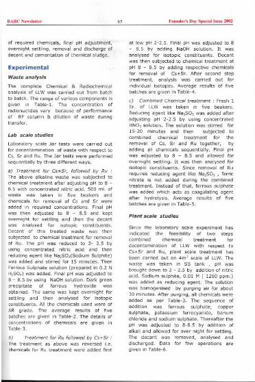
BARCN,w,',"" 65 Found,,', Day Sp,da' bm 2002
of required chemicals, final pH adjustment,overnight settling, removal and discharge ofdecant and cementation of chemical sludge.
Experimental
Waste analysis
The complete Chemical & Radiochemicalanalysis of LLW was carried out from batch
to batch. The range of various components isgiven in Table-!. The concentration of
radionuclides vary because of performance
of RF column & dilution of waste duringtransfer.
Lab scale studies
Laboratory scale Jar tests were carried outfor decontamination of waste with respect toCs, Sr and Ru. The Jar tests were performedsequentially by three different ways.
aJ Treatment for Cs+Sr, followed by Ru .The above alkaline waste was subjected tochemical treatment after adjusting pH to 8 -8.5 with concentrated nitric acid. 500 ml. ofwaste was taken in five beakers andchemicals for removal of Cs and Sr were
added in required concentrations. Final pHwas then adjusted to 8 - 8.5 and keptovernight for settling and then the decantwas ana lysed for isotopic constituents.Decant of this treated waste was thensubjected to chemical treatment for removal
of Ru. The pH was reduced to 2- 2.5 byusing concentrated nitric acid and then
reducing agent like Na,SO,(Sodium Sulphite)was added and stirred for 15 minutes. Then
Ferrous Sulphate solution (prepared in 0.2 NH,SO,) was added. Final pH was adjusted to
8 - 8.5 by using NaOH solution. Dark greenprecipitate of ferrous hydroxide wasobtained. The same was kept overnight forsettling and then ana lysed for isotopicconstituents. All the chemicals used were of
AR grade. The average results of fivebatches are given in Table-2. The details of
concentrations of chemicals are given inTable-3.
bJ Treatment for Ru followed by Cs+Sr :The treatment as above was reversed i.e.chemicals for Ru treatment were added first
at low pH 2-2.5. Final pH was adjusted to 8- 8.5 by adding NaOH solution. It wasana lysed for isotopic constituents. Decantwas then subjected to chemical treatment at
pH 8 - 8.5 by adding respective chemicalsfor removal of Cs+Sr. After second steptreatment, analysis was carried out for
individual isotopes. Average results of fivebatches are given in Table-4.
cJ Combined Chemical treatment: Fresh 1Itr. of LLW was taken in five beakers.
Reducing agent like Na,SO, was added after
adjusting pH 2-2.5 by using concentratedHNO, solution. The solution was stirred for
15-20 minutes and then subjected tocombined chemical treatment for the
removal of Cs, Sr and Ru together, byadding all chemicals sequentially. Final pHwas adjusted to 8 - 8.5 and allowed for
overnight settling. It was then analysed forisotopic constituents. Since removal of Ru
requires reducing agent like Na,SO, , ferricnitrate is not added during the combined
treatment. Instead of that, ferrous sulphatewas added which acts as coagulating agentafter hydrolysis. Average results of fivebatches are given in Table-5.
Plant scale studies
Since the laboratory scale experiment hasindicated the feasibility of two stepscombined chemical treatment for
decontamination of LLW with respect toCs+Sr and Ru, plant scale treatment hasbeen carried out on 4m' scale of LLW. The
waste was taken in SS tank, pH wasbrought down to 2 - 2.5 by addition of nitric
acid. Sodium sulphite, 0.01 M ( 1260 ppm.)was added as reducing agent. The solutionwas homogenised by purging air for about30 minutes. After purging, all chemicals wereadded as per Table-3. The sequence of
addition was ferrous sulphate, coppersulphate, potassium ferrocyanide, bariumchloride and sodium sulphate. Thereafter thepH was adjusted to 8-8.5 by addition of
alkali and allowed for over night for settling.The decant was removed, ana lysed anddischarged. Data for few operations aregiven in Table-5.
I

BARC Now,I,"" 66 Foond,,', Day Special T"no 2002
Table-l : Analysis of LLW
Table -2 : Treatment for Cs+Sr, followed by Ru
Note, * DF is with respect to initial activity.
Table -3 : Concentration details of co-precipitating chemicals
Table -4 : Treatment for Ru followed by Cs+Sr
Nate, * DF is with respect to initial activity.
Chemical AnalvsisTotal Solids 20 - 25 % as Sodium Nitrate
-;;H 12 - 12.5
Radiochemical Analysis"Ci/ml. kBo/lit.
Gross Beta 2.5 3.6 x 10' 925.0-1332Csm 5.1 - 6.2 x 10' 188.7-229.4Ru'" 4.0 - 4.5 x 10" 148.0-166.5Sr90 2.4 3.2 x 10'9 08.88-11.84
Cs+Sr Treatment Ru TreatmentAnalysis Activity after Treatment I Activity after Treatment
nH 8 8.5 8 - 8.5Radiochemical Ana'j;;Sis
"Ci/ml. ken/lit. DF* ." Ci/ml. kBo/lit. DF*Gross 1.0 1.5 x10" 370-555 2 3 1.2 1.6 x10" 44.4-59.2 19-26Csm 2.1 2.5 x10.9 7.77-9.25 23-27 2.0-2.5"'10" 7-9.25 23-28
4.0-4.5 x10" 148-168.5 1 3.2-3.5\x1O' 11.84-12.95 12-13-1.2-2.3-1;(10" 4.45-8.51 2-4 1.1 2.2 x10" 4.07-8.14 2-4
Chemicals Reactive ion Concentration in nnm.CuSO, Cu *' 40- 60K, Fe CN 0 FefCN 0" 60-90BaCI, Ba" 200-250Na, SO, SO;' 500-1000Fe I NO, , Fe ."3 25 50FeSO 9 Fe" 600-900Na SO, Reducino anent 1260
Ru Treatment Cs+Sr TreatmentAnal sis Activit after Treatment ActivJt;-,after Treatment
-;;-H 8 - 8.5 8 - 8.5Radiochemical Analysis
I' Ci/ml. kBa/lit. DF* ."Ci/ml. kBa/lit. DF*Gross p 5.7 8.9 x10" 210.9-329 3-5 1.3-1.8 x10'3 48.1-66.6 17-23Csm 4.8-6.0 x10" 177.6-222 1 3.0- 3.8 x10⁻³ 11.1-14.06 15-19Ru'" 3.1-4.1 x10" 11.47-15.17 10-13 3.1-4.2 x10" 11.47-15.54 10-13Sr90 (2.3-3.1)x10'4 8.51-11.47 1 1.2 2.3 x10" 4.44-8.51 2-4

BARC New,'et'" 67 Foood,,', Day Spedall",ue 2002
Table -5 : Combined chemical treatment
Note: * DF is with respect to initial actiYity.
Table -6 : Analysis of samples generated during plant scale treatment
Result and Discussion
1. The co-precipitation methods such astreatment for Cs+Sr followed byRuthenium and Ruthenium followed byCs+Sr offers very good DF for Cs, Sr andRu. The final DF with respect to initialactivity, obtained by both the methods,
were found comparable. Hence any of thetreatment method can be followed.
2. Laboratory scale Jar tests have indicated
the possibility of two step combinedchemical treatment. In first step, thepresence of reducing agent like sodiumsulphite in acidic medium, at pH 2-2.5,sodium sulphite, reduces the valencies ofRu and also prevents oxidation of ferrousions to ferric. Hence addition of thereducing agent in acidic medium isessential. In second step, combinedchemical treatment by addition of allchemicals sequentially and thereafteradjusting pH to 8-8.5 offers better DF for
Ru, Cs and Sr. The activity is confined tochemical sludge so obtained and thevolume reduction factor is around 100.
D«ontamination ofLLW byCombined Chemica' Treatment
I...8~..::c0
~".'s~~"e~ .1'1
-~ -" .~._- ~ ~- -,,- - ,-,--- --StepsofTreatment~
I.Gro.'-B~I~Cs-137 DRu-H1§..Sr-~
CombinedTreatmentAnalysis Activity after Treatment DF*pH 8 8.5
Radiochemical Analysis"CVml. kBa/lit.
Gross 0.95 1.1)xl0" 35.15-40.7 28-33Csm 1.8 2.1 x 10" 6.66-7.77 27-31Ru'" 2.2-2.9 x 10" 8.14-10.73 15-19Sr90 1.0 2.1 x 10" 3.7-7.77 2-5
Analysis Initial Activity After Combined treatment DF
pH 12.5-13.0 8-8.5
"CVml. kBq/lit. "CVml. kBq/lit.Gross (1.68 2.63)xI0" 621.6-973.1 (1.17-3.10)xI0" 43.29-114.7 8 14Csm (0.63-1.75)xI0'2 233.1-647.5 (0.23-1.31)xl0'3 9.51-48.47 13-27RuwS (1.46 3.89)xI0" 54.02-143.93 (4.63-3.24)xI0" 17.13-11.99 3 12Sr90 (4.80- 5.20) x 10" 17.76-19.24 (1.51-2.30)xI0" 5.59-8.51 2 3
BARCN,w,',"" 68 Fo"od,,', D,y Sp,",'I,"", 2002
References3. Based on the laboratory scale results, thetwo step combined chemical treatmentmethod has been adopted successfully onthe plant scale and nearly 1.5 lakh litersof waste have been treated at LWTP(T).The sludge has been conditioned in to thecement vermiculite matrix at solid wastemanagement facility. The combinedchemical treatment has offered
advantages like i) Substantial reductionof processing time ii) Reduction of sludgevolume ili) Avoid of multiple steps andcross contamination. iv) Reduction of aMan-rem exposure, etc.
1. Kulkarni Y., Samanta S.K., Bakare S.Y.,Kanwar Raj and Kumra M.S., "'Process fortreatment of intermediate levelradioactive waste based on radio nuclide
separation," Proc: Waste ManagementSymposia- 96 (WM-96), TusconCommunity Centre, Tuscon, Arizona, USA,Feb 25-29, 1996.
2. Mead, F.e. USAEC Document, WASH 275,231, 1954
This paper was adjudged as the Best paper in the Twelfth Annual Conference ofIndian Nuclear Society (INSAC-200I) held during October 10-12, 2001 at Centrefor Advanced Technology, Indore.
About the authors ...
M, S.G. Koro (M.Se- Chemistr(, fmmin 1986. He is a"ociated with pmce"involved in leaching >tudy of "rious cementradiooulci" hy chemical "eoemeot, evaluation
with reverse osmosis technique usmgLLW at Tarapur.
outa
M'R.G. Yeotik., ( M.Se- Chern., M.Tech.- Chemical Techoology from Nagpur Uoiversity), joinedMaoagemeot Divi"on, BARC, after gcaduation fmm 20th batch of BARC Traioiog School. Preseotly. he "Superiotenden" Laboratories, Waste Maoagemeot Facifiti", Tarapur. He is responsible foe carr(i09 outvarious developmeot activities for maoagemeot of all types of oudear wa>te and their possible adaptatioo00 plaut scale io additioo to oormal eoalytical support to the plaot. His maio field of work ioclud"developmeot of methods such as chemical "eatmeot of low level waste, cooditiooiog of iotermediate level
io cement matrix eod vitrificatioo of high level radioactive liquid wastes. His main cootributioo also ;oclud"pmeot and regular adaptatioo of various methods for evaluatioo of chemical durabifity and other pmperties of
waste pmduct,. He was a member of Co-ordiueted Research Pmgram of lntematiouel Atomic Eoergy Ageocy. He ishaviog about 4S putilicatioos to his credit.

BARC New,le"" 69 Found..', Doy 5\>«;011".e 2002
I, MrAjal Mishra B,Sc, (Engg,)Merhani,,'fcomAgraUni,"~,ty,joinedWaoleManagementDivision,
C'- BARC in 1979 affee g,"duallng from 22"" batch of Training School, BARC He is ove,"" responsible for, ' mnS
,
lrU"iO
,
n,
,
opeea
,
lion and
,
maintena
,
n
,
ce O
,
f va
,
riOUs
,
Ra
,
d Waste Manag
,
ement Fa
,
dillies at BARC comPlex
,
' Tarapur, He is alsO involved in a number of development studces ",Iated to t",atment of Low LevelRad'oartive "quid Waole and conditIoning mto oement matrix and final adaptation on the plant s"le, H"field of work also mcludes safe management of vanous of types of sol,d waole from various DAE sites atTarapur, ,n near surface d"posal fa"lcty and 'IS su~"llance, He has also part"ipated as mnsultant and
expert at Vienna in MEA Terhnceal Commiltees,
I Mr S.S.AU graduated in Chemicat Engineering from Dsmania Unive~ity in 1970, Aftee working with a" heavy chemical ,nduolry, he joined BARC in March '973, Fcom 1973 to 1997 May, he has worked at, Rajaolh., Atomic Powee Plant as In-Charge of Effluent Management unit, He was responsible for safe
" 'management of radioa"ive waole at RAPS and planning & augmentallon of Waste Management Facililles" including Construct/on, Commissioning & subsequent opeeatlon of Solar Evapo'"tlon Facility at RAPS, He
has geneeated and mmp,led the dald on waole management "'qul",ment of a 220 MW (e) PHWR, He hasparticipated In Pcoje" Design ",view of Waste Management Plants like NAPP, KGS, RAPP.3&4.
L

BARC Now,l,tt" 70
Foond,,', Day Sp,dall"o, 2002 I
IIII
II
I
End Plug Welding Of PFBR Fuelwith a 2.5 kW CW CO2 Laser
Tubes
Aniruddha Kumar, R. B. Bhatt and Arun KumarAd,"",d FoolFab,leotl"Fac",ty, BARC, Tacapo, -401 504
Rakesh Kaul, P. Ganesh, M.D. Ittoop and A. K. NathCeot,e foe Ad'"'"d T"heclogy, I,doce -452 013
IntroductionTable-l : Chemical compositions of clad tube & end plug (inwtOfo) Clad tubeA titanium-stabilized
fully austenitic alloyD9 (a 15Cr-15Ni-2 Mostainless steel),because of its superiorresistance toirradiation-induced
swelling and highercreep strength underirradiation, has been selected for fuel-clad
and wrapper applications in 500 MWePrototype Fast Breeder Reactor (PFBR). Fuelclad tube of PFBR is a 6.6 mm outer diameter
tube (wall thickness = 0.45 mm) made ofalloy D9. The two ends of fuel clad tube areencapsulated by weldin9 with end plugs madeof AISI 316M stainless steel (Fi9. 1).
C
0.04
C,17.2
'" "~"",,.~ ",'
Flg.l I Details of end plug of PFaR fuel pin
Table 1 presents chemical compositions ofthe materials of construction of clad tube and
end plug, respectively. An accepted weldshould have complete fusion of fuel cladtube/plug interface and should be free from
End Plu
~,~
S0.015
FeBal.
P
0.053
defects like porosity, inclusions and cracks.
End plug welding process has been qualifiedusing Pulsed Gas Tungsten Acc Welding(PGTAW) and this method has been adoptedto weld the end plugs. The objective of the
present study is to explore technicalfeasibility of using high power continuouswave (CW) CO, laser fo, making consistentlygood quality end welds of PFBR fuel pin.Being a non-contact process, lasee weldingdoes not generate active wastes in the formof used electrodes and defects like tungsteninclusions are completely eliminated.Moreover, it will also simplify glove boxoperation as it obviates electrodereplacement, arc gap adjustment etc. Sinceno information is currently available on laserweldability of alloy D9, it was essential tocarry out detailed investigation in this regard.
Background
Solidification cracking is one of the major
problems associated with austenitic stainlesssteel welding. The reason for solidification
cracking is attributed to the formation of lowmelting point eutectic phases at the grainboundaries of solidifying weld metal which

BARCN""k"" 71 Foond,,', Day Sp,dal "m, 2002
facilitates intergranular cracking under theinfluence of welding induced thermal
stresses'. The crack sensitivity of a particularweld metal is largely determined by itsprimary mode of solidification. Austeniticstainless steel welds, depending upon theirchemical composition, can solidify with
primary phase being either ferrite oraustenite. Primary ferrite solidified welds aremore crack resistant than primary austenitesolidified welds'.
.0"
N
.
..<,""' 0""
with po"tion, of alloy 09and AISI 31611 ,tamle«
Figure 2 presents positions of clad tube andend plug materials on WRC-1992 dia9ram'.
Alloy 09 (Cr" ~ 17 & Ni" ~ 15) solidifieswith completely austenite mode (with FN=O)under GTAW conditions. Completelyaustenitic mode of solidification along with
presence of titanium (segregates ininterdendritic regions and forms carbides andcarbosulphides) makes this alloy particularlysusceptible to solidification cracking duringwelding'. On the other hand, FA mode ofsolidification is predicted (with FN=9) for AISI
315M stainless steel (Cr" ~ 1904 and Ni,,=12). The composition of the fusion zone onthe tie line connecting points correspondingto alloy 09 and AISI 315M stainless steel is
determined by the degree of dilution of cladtube and end plug. For achieving desirableFA mode of solidification, the dilution fromclad tube should not exceed 28%.
Experimental
An indigenously developed 2.5 kW CW CO,laser system was used for laser welding. It
involved irradiating joint of the rotatingtubular specimens with a focused laser beam.Argon was used as the shield gas duringwelding.
Results & Discussion
Initial welding (laser power = 900W &welding speed =10-20 rpm) produced weldswith almost complete penetration and with
primary austenite mode of solidification. Oneof these welds was associated with a centre-
line crack (Fig.3). The welds also carriedcraters at weld termination sites (Figo4).Subsequent laser welds were made withhigher heat input (laser power = 2 kW;welding speed ~ 12-35 rpm). Use of higherheat input aimed at enhancing solidificationcracking resistance of laser welds throughachieving greater fusion of underlying end
plug material (with higher Cr,elNi" ratio)which serves to shift primary mode ofsolidification towards ferrite side. No defects
(except crater at weld termination site) werenoticed in the resultant welds. The welds still
exhibited primary austenite mode ofsolidification. Table-2 presents dimensions oflaser welds made with different parameters.
Next set of experiments involved welding withfocused laser beam displaced towards endplug side (displacement = 0.1-0.35 mm). Aslaser beam was progressively displacedtowards end plug side, the fraction of thefusion zone representing primary ferrite modeof solidification increased at the cost of that
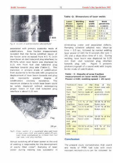
BARC New,le"" 72 Found,,', Day Spedal ",",2002
associated with primary austenite mode ofsolidification. Area fraction measurement
revealed that the ferrite solidified region ofthe fusion zone increased from 4-5 % (withlaser beam at clad tube/end plug interface) to95-96% when laser beam was displaced by0.35 mm from fuel clad tube/end pluginterface towards plug side (Table-3). Thistransition in primary mode of solidificationfrom austenrte to ferrite side with progressivedisplacement of laser beam towards end plugside represents greater degree ofsolidification cracking resistance. Themaximum distance to which laser beam could
be safely displaced without endangeringproper fusion of fuel clad tube/end pluginterface is about 0.25 mm
weld m,de
L""ded tube / end
Abrupt switching off of laser power at the end
of welding is responsible for the developmentof poorly filled crater'. Ramping of laserpower during welding was successful in
eliminating crater and associated defects.
Ramping schedule adopted was: slope-uptime = 0.5 sec, followed by normal weldinglaser power (2 kW) for 6 seconds (for rpm =25) and a slope-down time of 1 see. Duringwelding, laser beam was displaced by 0.25mm from clad tube/end plug interfacetowards plug side. Figure 5 presentsphotomicrograph of a sound weld with largelyferrite mode of solidification.
Table -3 : Results of area fractionmeasurement on laser welds (LaserPower=2 kW; welding speed = 25 rpm)
Conclusion
The present study demonstrates that soundend welds of PFBR fuel tube with crack
resistant microstructure can be obtained by
Table -2: Dimensions of laser welds
Laser Welding Weld WeldPower Speed width penetratioWatts r m mm n mm
900 10-20 1-1.1 0.45-0.501500 12 1.52-1.59 0.8-1.11500 25 1.45-1.5 0.51 0.582000 25 1.53-1.62000 36 1.4-1.5
Position of Aceo of the Acea of thelaser fusion wne fusion zone withbeam with permary primaryfrom fuel ferrite mode of austenite modedad Solidification of solidificationtube/pluginteetaceAt the 4-5 % of the 95-96 % of theinterface fusion wne fusion wne0.1 mm 13-28 % of the 72-87 % of thetowards fusion woe fusion wneend plu9side0.25 mm 70-82%oftho 18-30 % of thetowards fusion wne fusion wneend plugside0.35 mm 9596%ofthe 4 5 % of thetowards fusion woe fusion wneend plU9side --"
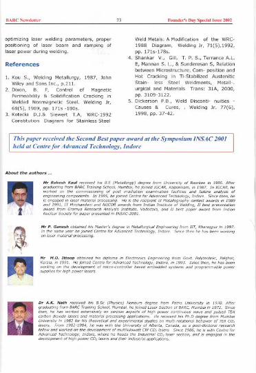
BARCNew,""" 73 Fouud,,', Doy Spedoll,"u, 2002
optimizing laser welding parameters, properpositioning of laser beam and ramping oflaser power during welding.
References
1. Kou 5., Welding MetaOurgy, 1987, JohnWiley and Sons Inc., p.211.
2. Dixon, B. F, Control of MagneticPermeability & Solidification Cracking in
Welded Nonmagnetic Steel. Welding Jr,68(5). 1989, pp. 1715 -1805.
3. Kotecki D.J.& Siewert T.A, WRC-1992Constitution Diagram for Stainless Steel
Weld Metals: A Modification of the WRC-
1988 Diagram, Welding Jr, 71(5),1992,pp. 1715-1785.
4. Shankar V., Gill, T. P. 5., Terrance A.L.
E, Mannan S. L., & Sunderesan 5, Relationbetween Microstructure, Com- position andHot Cracking in Ti-Stabilized AusteniticStain- less Steel Weldments, Metall-.urgical and Materials Trans: 31A, 2000,pp. 3109-3122.
5. Dickerson P.B., Weld Disconti- nuities -
Causes & Cures, Welding Jr. 77(6),1998, pp. 37-42.
This pilper received the Second Best pilper ilwilrd ilt the Symposium INSAC 2001held ilt Centre for Advilnced Technology, Indore
About the authors ...
Mr Rakesh Kaul .eeel,ed h" BE""duatmg Imm BARCwo.ked on the com.
components. In" /a,.. mateel,nd IT !"licchandanlawacd lcom Gcamya Reseaceh
II
II
III.I~r(
Mc P. GaneshIn the <omeon
Englneeclng Imm lIT,Indoce. Smce then he

BARC Now,l,tter 74 Found,,', Day Sp,dall"n, 2002
offu,' ",m,n"

BARC New,'ett" 75 Fouod,,'s Day Spedall"ue 2002
Development of a Repetitive WidelyTunable Single Mode TEA CO2 Laser, itsApplication on NH3 Laser and RelatedStudiesJ. Padma NilayaCo>e' oed "e>ma Techcology DivisiocBhabha Atomic Resweh Cectoe
The importance of a carbon dioxide laseroperating repetitively on a single longitudinalmode (SLM) either Dn one or multipletransitions in selective photochemical studiesis well recognised. Further, the generationof coherent radiation at longer wavelengthswith a carbon dioxide laser as the pumpsource plays a significant role in thesestudies. In this dissertation four importantfeatures of the pump laser, which, among
others, enhance the efficiency of both theabove-mentioned processes, are addressed.They are a) the single frequency operation ofthe pump laser, b) the wide tunability of theemission frequency of the pump laser withrespect to the absorption feature of themolecule of interest, c) the capability of the
pump laser to simultaneously operate onmore than one frequency and d) its
repetitive operation capability. In addition,the operation of molecular lasers (inparticular NH, laser) optically pumped byCO, laser providing coherent radiation in thelonger wavelength region also forms animportant part of this thesis.
In an isotopic mixture of molecules, selectiveexcitation and an eventual dissociation of
one of the species leading to the separationof isotopes is possible if the frequency of the
pump laser matches with the absorptionfeature of the molecule. The efficiency of
such selective multi photon dissociationprocesses depends strongly on the proximityof the emission frequency of the pump to theabsorption centre of the isotopic species ofint.erest. Chance coincidence of these two is
extremely remote. The operation of the
pump on single longitudinal widely detunablemode, therefore, is preferred.
The popular methods of obtaining SLMoperation viz., the hybrid or the injectionlocking configurations, offer limiteddetunability of the lasing mode, as the lasingbandwidth, governed by the broadening inthe low-pressure section, is small. In themethod reported in this thesis, on the otherhand, a judicious combination of the freespectral range (FSR) of the cavity and thepositioning of the loss line allowed only onemode to experience net gain resulting in SLMoperation with a detunability an order ofmagnitude more than that obtainable by theconventional methods. Under certainoperating conditions of this laser, emission oftwo pulses that originate from the intra-pulse temperature induced change of therefractive index, was observed" '. A cavitymode when appropriately located withrespect to the centre of transition can bepushed out of lasing due to this effect\Following this as the temperatureequilibrates the mode is pulled back in to thegain domain causing thereby the emission ofthe second pulse. The laser should thereforebe operated outside this double pulsingwindow for its use in multiphotondissociation experiments or as a pump forother molecular lasers. Remarkablestretching of the pulse from this mini laserwas also observed under conditions for whichoscillation on a higher order transverse modefollowed that on the TEMcomode with partialtemporal overlap between the two'.Judicious combination of spatial and spectral

BARC New,"tter 76 Founder', Day Speda' '»ue 2002
control helped realise such an oscillationcondition.
The vibrational energy levels of a moleculeget gradually closer due to anharmonicitywith increasing vibrational energy of themolecule making its absorption line centrered shifted with respect to the initiallyresonant incident pump laser frequency. Thecapability of a CO, laser to operatesimultaneously on a number of rotationalvibrational transitions greatly simplifies suchselective multi-photon excitation processesand results in higher dissociation yield,better selectivity, reduction in the thresholdfluence etc.
A CO, laser normally lases on a singletransition possessing the highest gain, as therotational thermalisation time is muchshorter as compared to the duration of thelaser pulse. Simultaneous oscillation on anumber of lines can be obtained if the gainto loss ratio can be made nearly the same onall these transitions. Selection of a set oftransitions on which simultaneous lasing canoccur is generally not possible by theexisting techniques. The judicious impositionof longitudinal mode control onto a resonatorcavity, the Q value of which increased withdecreasing wavelength in the 11-9 micronregion, made possible the simultaneousoscillation on all the four branches from alow pressure cw CO, laser'. This low powermultiline photon distribution wassubsequently amplified in a high-pressuresection in the hybrid configurations.Tailoring the Q value of the cavity can, inprinciple, generate any desired combinationof lasing lines. Injection locking on a weakgain line was achieved in a non-dispersiveTEA CO, laser cavity with moderate seedphoton power'. The success of thistechnique owed primarily to the utilisation ofa slave cavity with large FSR such thattuning its cavity length to some specificvalues actually offsets the large gaindifference between a strong and a weak line.This work gives rise to the prospect ofamplification of a low power multilinedistribution of photons in a non-dispersiveslave cavity. In course of this work, theimportant role played by spatial hole burning
effect in determining the emissioncharacteristics of a laser was elegantlybrought out in an experiment where thespatial hole filling rate was varied by twoorders of magnitude by utilising slow andfast axial flow CO, laser systems'.
To access the absorption features ofmolecules with no possible overlap with theemission frequencies of CO, laser, pumping asuitable molecular medium with the CO,laser emission can be an attractive methodof generating new coherent sources at longerwavelengths. A number of difficulties areencountered in the operation of an opticallypumped molecular laser (OPML). Efficientcoupling of the pump radiation into.the OPMLmedium while maintaining, at the sametime, high Q of the OPMLcavity is far fromsimple. The instabilities caused in the pumplaser as the unabsorbed pump retraces itspath back into it renders it unsuitable formany experiments. A novel cavityconfiguration where most of these problemscould be eliminated to a satisfactory levelhas been conceived and the performance ofthis versatile cavity has been demonstratedin the pulsed operation of an NH, laserpumped by a TEA CO, laser". To be notedhere that the performance of the opticallypumped molecular laser would also benefitby the detunable SLM repetitive operationcapability of the pump laser.
Apart from the suitable ~I'hissioncharacteristics, the other important attributeof a pump laser that decides the efficiencyand yield of selective photo-excitationprocesses IS its repetitive operationcapability. Spark gaps, by virtue of theiroperation in arc mode, are unsuitable forrepetitive applications and are normallyreplaced by thyratrons'. By rotating asuitably configured dielectric plate betweenthe electrodes of an ordinary spark gap, itwas possible to enhance the repetition ratecapability of a spark gap". The uniquegeometry of this device was exploited toobtain large number of advantages"."otherwise not possible by the conventionalcommand resonant charging scheme. Incourse of this work it was found that for fastdischarges, which normally is the case with

BARCNe",ld'" 77 Found,,', Day Spodal "suo 2002
TE lasers, the recovery of a switch isindependent of the energy transferredthrough it".
References
1. Observation of double pulsing in a singlemode TEA CO, laser caused by the effectof mode pulling and pushing, J. P. Nilayaand D. J. Biswas, BARC News letter, 189,90 (1999).
2. Observation of intra-pulse thermal effectinduced double pulsing in a single modeTEA CO, laser, J. P. Nilaya and D. J.Biswas, J. Phys D:Appl Phys 34, 78(2001).
3. Pulse stretching due partial temporaloverlap of two modes in a TEA CO, laser,J. P. Nilaya and D. J. Biswas, Rev SciInstrum 71, 579 (2000).
4. Four branch oscillation from a dual
polarisation cavity CO, laser, D. J. Biswas,J. P. Nilaya, and U. K. Chatterjee, ApplPhys B 57, 227 (1993).
5. Dual band multiline lasing from hybridCO, lasers, D. J. Biswas, J. P. Nilaya, andU. K. chatterjee, Opt Quantum Electron29, 501 (1997).
6. Evidence of injection locking in a nondispersive slave CO, laser, J. P. Nilayaand D. J. Biswas, Opt Engg 37, 1080(1998).
7. Effect of lon9itudinal flow velocity on theemission spectrum of CO, laser, D. J.Biswas, J. P. Nilaya, S. K. Sehgal, and U.K. chatterjee, J Appl phys 76, 1340
(1994).8. A versatile cavity for optically pumped
molecular lasers, J. P. Nilaya and D. J.Biswas, Rev Sci Instrum 72, 1343 (2001).
9. D. J. Biswas and J. P. Nilaya, ReviewArticle, Prog. Quantum Electron 26, pp 1-63 (2002).
10. Hi9h repetition rate operation of arotating dielectric spark gap, J. P. Nilaya,D. J. Biswas, B. S. Narayan, and U. K.Chatterjee, Rev Sci Instrum 65, 3590(1994).
11. Latch proof operation of a switch of ahigh repetition rate laser with D-CResonant charging, D. J. Biswas, J. P.Nilaya, and U. K. chatterjee, Rev SciInstrum 66, 4813 (1995).
12. A single switch as driver of two highrepetition rate lasers,D.J. Biswas, J. P.Nilaya, and U. K. Chatterjee, Opt Engg
36, 588 (1997). \13. Diode less operation of a resorantly
charged TE laser pulser, D. J. Biswas,J. P. Nilaya, Rev Sci Instrum 72,2505(2001).
14. On the recovery of a spark gap in a fastdischarge circuit, D. J. Biswas, J. P.Nilaya, and U. K. Chatterjee Rev SciInstrum 69, 4242 (1998).
II
Dr (Ms) J. Plldmll NiIIlYIl received the "Indjlln Lllser Associlltion Best Ph.D. Thesis
Awllrd"jor her thesis presented llt the Nlltionlll Lllser Symposium, CAT, Indore,200/
About the author ..
Padma Nilaya ,eeei,ed h" MSo.,,",while MDRS. BARCin 1992
She lotheB.s, ,nd Shesodet, in 1999. H" ,."a"h inteceot indudeothel, 'ppli"tion to I>otope"p",tion. She h"2002
Dr 1991 .odof the,n the
Phy,i,,'at eohe..nt mid-intmed ,Due", ond
D twm the Uni""lty ot Mumba;In
twm
BARC New,le"" 78 Found,,', Day Spedal '".e 2002
Heavy IonReactions
Induced
L.M.PantNe"",Sh,bh,
°""'°0Rco""h Ceo"e
Nuclear fission is a process whereby a heavynucleus splits into two fragments ofcomparable mass. One of the main
characteristics of the fission process is,therefore, the mass distribution of the fission
fragments. From the early days, it wasestablished that in the low energy fission ofthe actinide nuclei, the fragment massdistribution is highly asymmetric, and thiswas attributed to the influence of the
doubly closed shell in the heavy fragmentmass region. With the advent of heavy ionaccelerators, it has been possible to studythe fission process in detail by populatingcompound nuclei over large excitation
energies and angular momenta by variousentrance channels using heavy ionreactions. As the excitation energy of thefissioning nucleus is increased, the massdistribution becomes more symmetric dueto washing out of the shell effects at
high excitation energies [1].
Another important aspect in the study of thefusion-fission reactions is the fission-
fragment angular distributions, which have
also been investigated in great detail in therecent years [2J. The interest in this fieldhas been renewed with the observation
that the fragment angular distributions inmany target projectile systems showanomalous features when they arecompared to the standard saddle point
statistical model (SSPSM) calculations [3J.
The SSPSM model accounts well for thefragment angular distributions in the lightion induced fission reactions however,anomalous angular distributions have beenreported mainly for heavy ion reactions usingactinide target nuclei and are attributed tobe due to an admixture of non-equilibrated
Fusion- Fission
fission events such as pre-equilibriumfission, fast fission and quasi-fission alongwith the normal compound nuclear fissionevents. Mass distributions following such anadmixture would be expected to be broaderthan those for normal fission because noncompound fission reactions are expectedto have more asymmetric componentarising due to incomplete equilibration inmass degree of freedom.The onset of suchnon-equilibrated fission events is governedby the dynamics of the fusion and fissionprocesses in the heavy ion reactions.
The dynamics of the fusion-fiS$ion reactionscan also be explored by studying the pre-scission neutron multiplicities in the fissionreactions. It is observed that in a largenumber of heavy ion induced fusion-fission reactions, the pre-scission neutronmultiplicities are also anomalously largerthan that predicted by the SSPSMcalculations [4J. The excess of pre-scissionneutron multiplicityis now attributedto bedue to a time delay in the fission processarising due to dynamical effects in the fissionprocess.
In the present work, we have addresseddifferent dynamical aspects in the study ofheavy ion induced fusion-fission reactionsthrough mass-energy correlations, massdependent variation of fission fragmentanisotropy and measurements of pre-scission neutron multiplicities. We havemeasured the mass and kinetic energydistributionsof fission fragmentsusing "0and >OFprojectiles on '09Bitarget at energiesaround the Coulomb barrier for fusion. In thesecond part of the measurements, we havestudied the fission fragment angular aniso-tropies as a function of fragment massin two

BARCN,w""'" 79 Foood,,', Day Sp,dal"'" 2002
target-projectile systems namely "B+"'Npand "O+"'Bi having different entrancechannel mass asymmetries and lying oneither side of the Bussinaro Gallone critical
mass asymmetry, aBG' Finally, the pre-
scission neutron multiplicity measurementshave been carried out in the "H"'Bi
reaction, which have provided newinformation on the fission time delay inthis system resulting due to the dynamicsand energy damping in the fission process.The experiments were carried out usingheavy ion projectiles Irom the 14MV BARC-TIFR Pelletron Accelerator Facility at Mumbai.
The design and development of the LargeArea Position Sensitive Ionization Chamber
(LAPSIC) [5J, formed the main cornerstonefor carrying out the fission coincidencemeasurements described in this work. Fig. 1shows LAPSIC in the Pelletron Beam Hall.This detector is used for simultaneous
measurement of energy, mass, charge andangle of emission of the reaction products. Itconsists of two identical gas chambershaving a common cathode. Each half has afour-element anode section for particleidentification and a a-grid to measure the
angle of the particle. The detector isnormally operated with P10 gas in flowmode. The detector subtends a solid angleof 40 mSr at the target. The entrance
window at 121 em from the target centermakes it suitable for time of flightmeasurements of the reaction products. Thesignals from the G-grid are read out via thedelay line method.
Mass Energy Correlations in160+209Bi and 19F+2O9Bi Reactions
The mass and kinetic energy distributions ofthe fission fragments are decided during thetransition from saddle to scission stages inthe fission process and therefore can revealimportant information about the reactionmechanisms involved in the fusion-fissiondynamics in heavy ion induced reactions.Studies of mass and energy correlationswere carried out for the "0 and "H"'Bisystems over a wide range of excitationenergies (Eo=30-50 MeV)[6].
The experiment was carried out using a 60"m silicon surface barrier detector and theLAPSIC, kept at the fission folding angle todetect the complementary fragments.Experimental arrangement was similar tothat as shown in Fig. 5. The solid statedetector was kept at 70" with an angularopening of t 3' and the LAPSICwas kept at amean angle of 90' with an__acceptance angleof t 9.8' on either side of tfie beam fordetecting the coincident events. The peakof the folding angle was well covered forboth the systems with this angularacceptance. The "0 and "F beam energieswere varied to cover both below and abovebarrier energy regions for the respectivesystems.
The pulse heights from the two detectorswere converted into the post-scission kineticenergies of the two fragments by an eventby event iterative analysis. The center ofmass energies of the fragments were derived
after kinematic trans-formationassuming full momentumtransfer to the compoundnucleus. These energies werefurther corrected for neutronevaporation effects to obtainthe pre-neutron emissionmasses by using the massand momentum conservationrelations.
Flg.l. LAPS!S lITth, P,II,troIT a"mHall
Fig. 2 shows the variance, 0/
of the fragment massdistributions as a function of
the bombarding energy. The
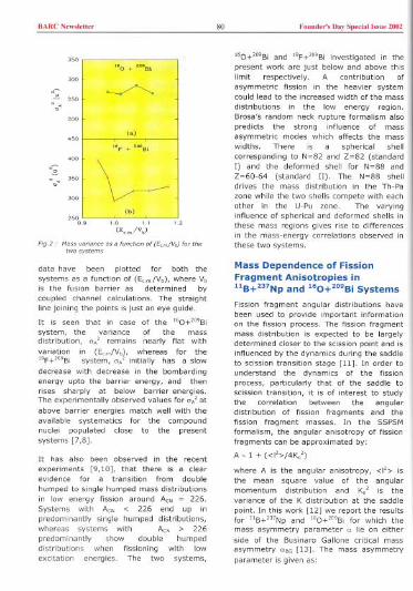
BARCNow,""" 80 Found,,', D"y Sped"' I"ue 2002
"0 + ""BI
"~ '"0 ~"0
(0)
"F + ""8\
"
\~~0
(b)'"0
0.'
FIg.2, l1aoo"cian,e "a faniMn of (E..fV,) foethetwo,y,tem,
data have been plotted for both thesystems as a function of (E.mNb), where Vbis the fusion barrier as determined bycoupled channel calculations. The straight
line joining the points is just an eye guide.
It is seen that in case of the "O+"'Bi
system, the variance of the massdistribution, 0,' cemains nearly flat withvariation in (E.mNb), whereas for the"F+"'Bi system, 0,' initially has a slow
decrease with decrease in the bombardingenergy upto the barrier energy, and thenrises sharply at below barrier energies.The experimentally observed values for 0/ at
above barrier energies match well with theavailable systematics for the compoundnuclei populated close to the presentsystems [7,8].
It has also been observed in the recent
experiments [9,10], that there is a clearevidence for a transition from double
humped to single humped mass distributionsin low energy fission around A" = 226.Systems with A" < 226 end up inpredominantly single humped distributions,whereas systems with A" > 226predominantly show double humpeddistributions when fissioning with lowexcitation energies. The two systems,
fbO+mBi and "F+'O9Bi investigated in thepresent work are Just below and above thislimit respectively. A contribution ofasymmetric fission in the heavier systemcould lead to the increased width of the mass
distributions in the low energy region.
IBrosa's random neck rupture formalism alsopredicts the strong influence of massasymmetric modes which affects the masswidths. There is a spherical shell
I
corresponding to N=82 and 2=82 (standardI) and the deformed shell for N=88 and2=60-64 (standard II). The N=88 shelldrives the mass distribution in the Th-Pazone while the two shells compete with eachother in the U-Pu zone. The varying Iinfluence of spherical and deformed shells inthese mass regions gives rise to differencesin the mass-energy correlations observed in Ithese two systems. I
Mass Dependence of FissionFragment AnisotrDpies in"B+237Np and 160+209Bi SystemsFission fragment angular distributions havebeen used to provide important information
on the fission process. The fission fragmentmass distribution is expected to be largelydetermined closer to the scission point and isinfluenced by the dynamics during the saddleto scission transition stage [11]. In order to
understand the dynamics of the fissionprocess, particularly that of the saddle toscission transition, it is of interest to studythe correlation between the angulardistribution of fission fragments and thefission fragment masses. In the SSPSM
formalism, the angular anisotropy of fissionfragments can be approximated by'
A-l + «I'>/4Ko')
where A is the angular anisotropy, <I'> is
the mean square value of the angularmomentum distribution and Ko' is thevariance of the K distribution at the saddlepoint. In this work [12] we report the resultsfor "B+mNp and "O+'O9Bi for which themass asymmetry parameter 0 lie on eitherside of the Businaro Gallone critical massasymmetry DCG [13]. The mass asymmetryparameter is given as:
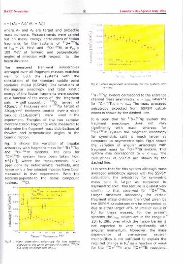
BARC New,leti" 8l Found,,', nay Spedal b,", 2002
a~[(A,-Ae)/(A,+Ae)J
where A, and Ac are target and projectilemass numbers. Measurements were carriedout on mass, energy correlations of fissionfragments for the systems of "B+mNpat E'ob~ 76 MeV and "O+"'Bi at E"b~
100 MeV at forward and perpendicularangles of emission with respect to thebeam direction.
The measured fragment anisotropies
averaged over all fragment masses matchedwell for both the systems with thecalculations of the standard saddle point
statistical model (SSPSM). The variations ofthe angular anisotropy and total kineticenergy of the fission fragments were studiedas a function of the mass of the fragment
pair. A self supporting "'Bi target of420"g/cm' thickness and a mNp target of220ag/cm' thickness coated over a nickelbacking (114"g/cm') were used in the
experiment. Energies of the two comple-mentary fission fragments were measured todetermine the fragment mass distributions at
forward and perpendicular angles to thebeam direction.
Fig. 3 shows the variation of angularanisotropy with fragment mass for "B+mNpand "O+mTh systems. The data for"O+mTh system have been taken fromref.[14], where the measurements havebeen done by radiochemical methods, andhence only a few selected masses have been
measured in that experiment. Both thesystems populate to the same compoundnucleus, N'Cf.
.. .°' [w]
.~~
'" , '" " ," " = '0 -0AHm,- A_m.~," (u)
Fig3 anisotmpy
. ".ti.ti..i.~.
C<
.'.".""", . I""'M"'."'".mu."."..""
"u"", A, """"" (uj
F'g.4 .. Ma% dependent anisotmpy for the system with
"B+mNp system correspond to the entrancechannel mass asymmetry, a > ass, whereasfor "O+mTh, a < °SG' The mass averaged
anisotropy expected from SSPSM calcul-
ations is shown by the d~hed line.It is seen that for "B+I"Np system thefragment anisotropy does not varysignificantly with mass, whereas for"O+mTh system the fragment anisotropyfor symmetric split is much larger ascompared to asymmetric split. FigA showsthe variation of angular anisotropy withfragment mass for "O+mBi system. Thissystem also corresponds to ° < °eo. Thecalculations of SSPSM are shown by thedashed line.
It is seen that for this system although mass
averaged anisotropy agrees with the SSPSMcalculation, the anisotropy for symmetric
mass split is larger as compared toasymmetric split. This feature is qualitativelysimiliar to that observed for "O+mTh.
Larger observed anisotropy for certainfragment mass divisions than that given bythe SSPSM calculations can be interpreted asdue to either larger <I'> or smaller value ofKo' for these masses. For the presentsystems the 1m" values are in the range of2511 to 2811, over which the fission barrier is
not expected to vary significantly withangular momentum. Moreover, the massdependence of pre-scission neutron
multiplicities is not sufficient to explain therequired change in K/ as a function of massfor the "O+mTh and "0+'55Bi reactions.
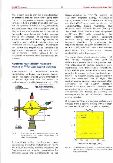
BARC New,'e"" 82 Found,,', Day Spedal "me 2002
The present results may be a manifestationof entrance channel effect while going fromUs to "0 projectiles In the two systems, interms of" being greater or smaller than ",G'For the systems for which a > VaGthe resultsare consistent with the assumption that thefragment angular distribution is decided atthe saddle point during the fission processand is not affected by the mass divisionwhich is decided at a later stage during thetransition from saddle to scission. Howeverfor systems with" < naG, larger anisotropies
for symmetric fragments as compared toasymmetric fragments may indicate thatthe dynamical paths followed by thefragments of different mass asymmetries aredifferent.
Neutron Multiplicity Measure-ments in 228UCompound System
Measurements of pre-scIssion neutronmultiplicities in heavy ion induced fusion-fission reactions provide useful informationon fission dynamics and the effects ofnuclear viscosity on the fission process [15].
",-
~="".~
" .-.---,,~ .~-,~~-~.:=.:::=-
="--FigS Schematic of the
mea,ucemeM of
neutcon multiplicity
To investigate further the fragment massdependence of neutron multiplicities in heavy
ion induced reactions, we have measured thefragment-neutron angular correlations foremission along and perpendicular to the
fission direction for >OF+mSi system at108 MeV projectile energy. As shown inFig. 5, a silicon surface barrier detector (Fl)and the LAPSIC were used to detect the
complementary fission fragments. Theneutrons were detected by two (6inch . '5inch thick) NE-213 neutron detectors placedat 90" and 152" with respect to thebeam direction to detect coincidentneutrons along and perpendicular to thefragment direction. Sy measuring thefragment-neutron angular correlations at -0' and - 90", one can deduce the averagepre-scission and post-scission neutronmultiplicities in the fission process.
The pulse shape discrimination property of
the NE-213 detfctors was used todifferentiate neutrons from the gamma rays.The efficiencies of neutron detectors weredetermined from Monte-Carlo simulations.
Pre-scaled singles fission events were alsorecorded to obtain neutron multiplicity perfission. The neutron energy was determinedfrom the measured time of flight. Theneutron energy spectra were obtained aftercorrecting for the neutron detectionefficiency for each neutron detector. Theparameters for pre-scission and post-scissioncomponents are derived by carrying outmoving source fits to the observed neutronenergy spectra.
It is assumed that pre-scission neutrons areemitted from a source moving with a centerof mass velocity of the compound system.
"FT~'B'
- AUCE- PACE2
" 2
~----
030 50 5535 40 45
Excitation Energy (MeV)
Fig. 6 . ne"con
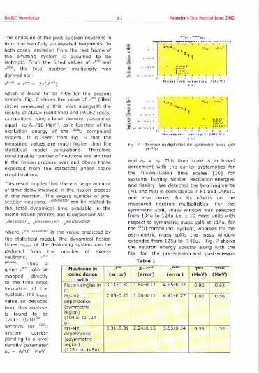
BARC Newsleu" 83 Found,,'s Day Special hsue 2002
The emission of the post-scission neutrons isfrom the two fully accelerated fragments. Inboth cases, emission from the rest frame ofthe emitting system is assumed to beisotropic. From the fitted values of vwe and,"", the total neutron multiplicity wasderived as:
v'V'" = vW + 2x(V"")
which is found to be 4.06 for the presentsystem. Fig. 6 shows the value of vW (filled
circle) measured in this work alongwith theresults of ALICE (solid line) and PACE2 (dots)calculations using a level density parameterequal to Aw/lO MeV", as a function of theexcitation energy of the mU compound
system. It is seen from Fig. 6 that themeasured values are much higher than thestatistical model calculations. Thereforeconsiderable number of neutrons are emitted
in the fission process over and above thoseexpected from the statistical phase spaceconsiderations.
This result implies that there is large amountof time delay involved in the fission pmcessin this reaction. The number of pre-scission neutmns, can be related to
the total dynamical time available in thefusion-fission pm cess and is expressed as:
v'" (""»J = vwe1m,,","') - vW I'"'w""')
where v'" ('""v"",) is the value predicted bythe statistical model. The dynamical fissiontimes "'>voooof the fissioning system can bededuced from the number of excessneutrons, vW(ex,"») Thus agiven V'" can bemapped directlyto the time sinceformation of thenucleus. The ",>;Coovalue as deduced
from this analysisis found to be
120(il0)xl0'"seconds for mU
system, corres-ponding to a leveldensity parameterao = AI10 MeV"
~~M
~..~.5£i
.n
FIg. 7 : multiplicities fo, symme"lc mass split
and a, = ar. This time scale is in broadagreement with the earlier systematics forthe fusion-fission time scales [16] forsystems having similar excitation energiesand fissility. We detected the two fragments(M1 and M2) in coincidence in F1 and LAPSICand also looked for its effects on the
measured neutmn multiplicities. For thesymmetric split, mass window was selectedfrom 104u to 124u i.e. i 10 mass units with
respect to symmetric mass split at 114u, forthe mU compound system, whereas for theasymmetric mass splits the mass windowextended from 125u to 145u. Fig. 7 showsthe neutron energy spectra along with thefits for the pre-scission and post-scission
Table 1
Neutrons in v'" 2xV'" v T,rn T""coincidence (error) (error) (error) (MeV) (MeV)
withFission singles in 3.11iO.30 1.84iO.12 4.95iO.32 0.90 0.63F1MI-M2 2.83iO.25 1.58iO.11 4.4ltO.27 1.00 0.56
dependence(symmetricregion)(104 u to 124uM1-M2 3.3HO.31 2.24iO.15 5.55iO.34 0.58 1.35dependence(asymmetric
i) to 145u\
BARC New,'eUoc
components for "'U compound systemsymmetric split region. The values for""", TP'. and TPP"are listed in Table 1 forboth the integral and mass dependentmeasurements. For the mass dependentmeasurements we find that vpm is enhancedfor asymmetric splits as compared tosymmetric splits and this is attributed to thevariations in the fragment mass distributionsat different stages in multiple chance fissionat medium excitation energies [17].Conclusions
In conclusion, the present work concerns theinvestigations of the dynamics of heavy ioninduced fusion-fission reactions throughmass-energy correlations of fissionfragments, mass dependence of fissionfragment anisotropy and also the studies onthe pre-scission neutron multiplicities inthe fission reactions. The sheli effects seemto play an important role in deciding themass widths in case "F+'"'Bi reactionat below barrier energies. In the"B+"'Np(a>aoG) reaction, the fragmentanisotropy is seen to be neariy independentof the fragment mass whereas for the"O+'O9Bi("<a'G) system, the anisotropy isseen to decrease with increasing fragmentmass asymmetry. The results are discussedon the basis of the statistical model offragment angular distributions and massdivision in the fission process. Pre-scissionneutron multiplicities have been measuredfor the first time in the fission of "'Ucompound system and the results suggestthat there is large dynamical delay[-120(>10)/l0'" seconds] in the fissionprocess in this system. The enhanced valuesof neutron multiplicity for asymmetric splitsas compared to symmetric splits issuggestive of the existence of multiplechance fission at medium excitationenergies. The present experiments carriedout with various target-projectile systemshave provided important results from thepaint of understanding the various dynamicalmodels of the fusion-fission process.
Acknowledgements
I am thankful to Dr. R.K.Choudhury for hiscontinuous guidance and motivation for this
84Foundoc', Day Speda' hm 2002
work. I am also grateful to ali thecoliaborators in this work for their kind helpand support.
References
1. R. K. Choudhury, A. Saxena, V. S.Ramamurthy, D. M. Nadkarni and S. S.Kapoor, Nucl. Phys. A463 597 (1987).
2. A.Bohr in Proceedings of the SecondUnited Nations International Conferenceon Peaceful Uses of Atomic Energy,Geneva, 1958 (United Nations, NewYork, 1958) vol.15 p 398.
3. V. S. Ramamurthy, S. S. Kapoor, R. K.Choudhury, A. Saxena, D. M. Nadkarni,A. K. Mohanty, B. K. Nayak, S. V. S.Sastry, S. Kailas, A. Chatterjee, P. Singhand A. Navin, Phys. Rev. Lett. 6S, 25(1990).
4. A5axena, A.Chatterjee, R.K.Choudhury,S.S.Kapoor and D.M.Nadkarni, Phys.Rev. C49, 932 (1994).
5. L. M. Pant, D. C. Biswas, B. V. Dinesh,R. G. Thomas, A. Saxena, Y.S5awantand R.K. Choudhury. Communicated toNIMA (2001).
6. L. M. Pant, A. Saxena, R. K. Choudhuryand D. M. Nadkarni. Phys. Rev. C542037 (1996).
7. D. J. Hinde, H. Ogata, M. Tanaka, T.Shimada, N. Takahashi, A. Sinohara, S.Wakamatsu, K. Katori and H. Okamura,Phys. Rev. C39 2268 (1989).
8. M. G. Itkis, Yu. Ts. Oganessian, G. G.Chubarian, V. S. Salamatin, A. Ya.Rusanov and V. N. Okolovich,(Proceedings of the XV EPS Conferenceon Low Energy Nuclear Dynamics(LEND-95), St. Petersburg, Russia,1995, edited by Yu. Ts. Oganessian(World Scientific, Singapore 1995) p1n.
9. I. V. Pokrovsky, M. G. Itkis, J. M. Itkis,N. A. Kondratiev, E. M. Kozulin, E. V.Prokhorova, V. S. Salamatin, V. V.Pashkevich, S.I. Mulgin,A. Ya. Rusanov,S. V. Zhdanov, G. G. Chubarian, B. J.Hurst, R. P. Schmitt, C. Agodi, G. Beliia,L. Calabretta, K. Lukashin, C.Maiolino,A.Kelic, G. Rudolf, L. Stuttge and F.Hanappe, Phys. Rev. C62 014615(2000).
BARC N'w,l,u", 85 Fo.nd,,', Day Spedo""., 2002
10. K.-H. Schmidt, A. R. J.nghans, J.Benlliure, C. B6ckstiegel, H. -G. Clerc, A.
Grewe, A. Heinz, A. V. Ignatyuk, M. deJong, G. A. Kudyaev, J. MOiler, M.
PfUtzner, and S. Steinhauzer, Nucl.phys. A63D 208c (1998).
11. R.Freifelder, M.Prakash and
J.M.Alexender, Phys. Rep. {\bf 133},315(1986)
12. L. M. Pant, R. K. Choudhury, AlokSaxena and D. C. Biswas. EUr. Phys. J. A11(1) 47-58 (2001).
13. M.Abe, KEK Report No.86-26, KEK, TH-28.1986
14. B. John, A. Nijasure, S. K. Kataria, A.Goswami, B. S. Tomar, A. V. R. Reddyand S. B. Manohar, Phys. Rev. CS1,165 (1995).
15. J. O. Newton. Pramana 33 175 (1989).16. D. J. Hinde, H. Ogata, M. Tanaka, T.
Shimoda, N. Takahashi, A. Shinohara, S.Wakamatsu, K. Katori and H. Okamura,Phys. Rev. C39 2268 (1989).
17. L. M. Pant, Alok Saxena, R. G. Thomas,D. C. Biswas and R. K. ChoudhuryCommunicated to Eur. Phys. J. A (2002).
Dr L.M.Plmt's thesis work on "Heavy-iOit inducedfusion-fission reactions" was
awarded the best thesis presentation in the 4(/h DAE-BRNS Symposium onNuclear Physics held at Saha Institute of Nuclear Physics, Kolkata duringDecember 26-30.2001.
About the author ...
Dr L.H.Pant fM.Sc. - Phy,ks, Lucknow Unlve"lty) g"duated from the 31" batch of the BARC
T"lnlng School and joined Nude., R",eateh "'00"<0", at Srinagar (K..hm/r) In 1988. Since 1990,he I' working In the Nuclear Phy,le< DM,ion In variou, experlm,ntal activit/", u,'ng the Pellelron
Accole,.", Facility. He obtained hi, Ph.D. degree from Mumbai Unive,,/ty in 2001. Hi' ""earchInte""" include "udylng the dynamical ..pem of heavy-Ion Induced fu,ion.n"ion react/on,. He h..made ,;gn/ficant contribution< In the ma,,-energy correlation< and neutron multiplidty me..u",men"of ""ion fragmen". He h.. participated in an experiment at LNL, Legnaro, Italy, u,lng the neufronball facility fa, "udying the n"ion dynamle< In the 'ynth",l, of Super Heavy Elemen" (SHE). HI'primary cont,/but/on, ace /n th, d"'ign and development of po,Won "'"'it/ve ionl,.tion chambe"
and liquid «Intl/lato".
BARC News'eU" 86 Found,,', Day Spedall",ue 2002
Solvent Effects on the Reaction ofOrganohaloperoxyl Radical with BovineSerum Albumin: A Pulse Radiolytic Study
Rayi Joshi and T. MukherjeeRadiotloo Chemlst,y & Chem;cal Dycoml" DlvlslooShobha Atom;c Rooe",h Ceetee
Abstract
uolike in dilute
Ob>eMdwith that
Introduction
The ,adiation-induced modification, damage,protein-protein and protein-DNA cross-linking is a subject of interest to radiationchemists, biologists and clinicians. The redoxreaction kinetics of various proteins andenzymes in dilute aqueous solutions havebeen well reported [2] but the reactions,which take place In cellular environment, areexpected to be different compared to thosein a dilute aqueous solution. This is ofsignificance due to the fact that biologicalsystems have high viscosity and self-assembly, which inceeases efficiency of thebiological processes. It is recognized thatcharge migration can facilitate transport ofradical-centre away from the initial site. Thusthe harmful ceoss-links can be formed atamino acids far away from the site where theprimary reaction occurs. The effects ofsolvent polacity and viscosity on the freeradical induced oxidation reactions ofproteins with free radicals, though veryimportant, have not been reported. Thedifficulty in studying oxidation reaction inviscous medium arises because of the highconcentration of solutes necessary forincreasing the viscosity of the medium. Thekinetics and mechanism of reduction reactionof BSA are known to be affected by solventproperties [3,4].
Experimental
Pulse radiolysis of the solutions has beenperformed by 7 MeVelectron pulses of 500nano-seconds duration using the linearelectron accelerato, In RC &CD Division,BARC.The energy deposition by high-energyelectrons, Ionizing radiation, producestransient species in micro-molarconcentration in the medium. Appropriatechemical system is used to convert thesetransient species into another specifictransient species to study the desiredchemical reaction. The primary speciesproduced upon radiolysis of watec are:
7 MeV electeoes
H,O . e", H,OH.. (1)
The solutes we,e present In a mediumcontaining glycerol (45 wt%), 2-propanol (3M), phosphate buffer (2 x 10's mol dm3) andCCI, (4 x 10' mol dm'3). The viscosity of thismedium has been measured to be 7.7 cpwith Analytical Viscometer AV-250(DjScientific) and Ostwald viscometer. Thedielectric constant of this medium (ca.63.66) is lowe, than that of pure wate,(78.5). The dielectric constant of themedium has been calculated by taking thealgebraic sum of the dielectric constant of acomponent multiplied with its mole fraction.
Glycerol was added to increase the viscosity

BARC N<w"et'" 87 Foond,,', D.,. 5.«'.'1"0< 2002
99330f the medium and 2-propanol wasused to dissolve CCI,. Glycerol and 2-propanol scavenge Hand 'OH radicals toproduce species un-reactive in the time scaleof observation, The reactions, which takeplace, are:
HIOH+CH,CHOHCH,/glycerol ':>H,/H,O+CH,C'OHCH,/glycerol'CI, + e,; ':> CI' +CCI,CCI, + 0, ':> CCI,O,CCI,O, + S ':> CCI,O,-+ S.'
The transients were then followed by kineticspectrophotometry from nano-seconds tomilli-seconds in the wavelength range of200-800 nm. The measurements were doneat 26 'c. The error in the measurement ofrate constants is . 10 %. Trichloromethyl-peroxyl radical (CCI,O,) is an organo-haloperoxyl radical which causes one-electron oxidation of the solute along withaddition and is used to study solvent effectson the reaction of peroxyl radicals withorganic solutes [5]. Charged species areproduced in the reaction 4 from unchargedspecies and so the reaction also depends onthe polarity of the medium.
Results and Discussion
Effect of viscosity
Transient absorption spectrum obtained fromthe reaction of BSAwith CCI,O, at pH 6.8 inthis medium shows (Fig. 1) simultaneousdecay of 460 nm absorption and growth of410 nm absorption (inset of Fig. 1) after thefirst step of formation of absorption at thesetwo positions (scheme 1 & 2). This suggestssome radical transformation, which has notbeen reported earlier in dilute aqueoussolutions.
Transient absorption spectrum recorded forthe amino acids, tryptophan, tyrosine anddisulfide links, more prone to reaction withCCI,O" suggest that the transientabsorption at 410 and 460 nm is due totyrosine (TyrO") and tryptophan (Trp')radicals, respectively. In this medium Trp'radical has been found to have transientabsorption maximum at 460 nm instead of
L
(2)
(3)(4)
....,
o...~ -\0""
~.
'00050 ...-
003~\ -:: 00025 ! '
... \ .\ --002~ \\ -~
\
\
0,01
0.00300
Fig, 1
510 nm peak observed in dilute aqueoussolutions. However, 460 nm transient
absorption decayed at a rate of 8.8 x 10' s"(first order) and second step of growth ofabsorption at 410 nm has been found to be1.0 x 10' s". Similar transient absorptionspectrum has been observed in the reaction
of BSA with CHCI,O, at pH 6.8 in thismedium confirming that the transientabsorptions are due to reaction with organo-haloperoxyl radical only. The measuredreaction rate constants with CHCI,O,' radical(0 ~5,88) are little lower (Table 1) than thatwith CClP, (0 ~ 5.88), in agreement withthe reduced Taft parameter (0). The
antioxidant effect of ascorbate in scavengingprotein radical has also been observed in thismedium with k ~ 2.4 x 10' dm' mol" 5'.
"'~
t'........
10)
'000
TIm.!...,
Fig, 2

BARC New""",, 88 Found,,', Day Sp,dall,"u, 2002
Second step formation of tyrosine radicalreduces to even lower rate at 90% vlvglycerol and pH 6.8 (Fig. 2b). Such radicaltransformation is reported for lysozyme (aprotein) in dilute aqueous solution but hasnot been observed in the present medium.This suggests even some conformationalchanges of protein in this medium.
The rate constants for the reactions studiedare given ill table 1.
Table 1 : Rate constants for the reaction of differentsolutes with CCI,O, radical
.HN.CH.CO.
CHz
~J ~~
.HN.CH.CO
cgQH2 .
-TrpH- -Trp'--
Scheme 1 I Form,tion of teyptoph,n "dic,!
.HN.CH.CO. -HN.CH.CO. -HN-CH.CQ.
wJH2 + ~CH2-- wJH2~H
-TyrOH-
Scheme 2 . R,dical t"n,form,tion from teyptoph,n totyrosine
-HN-CH-CO.
~2-Ty,O"-
The rate constants have not been found to
reduce in proportion to increase in viscosity.This suggests that diffusion affects the rateconstants but is not the only factor in thesereactions.
Effect of pH
Transient absorption spectrum obtained fromthe reaction of BSA with CCI,O, in thismedium at pH 10 also shows (Fig. 3)
simultaneous decay of 460 nmabsorption and growth of 410 nmabsorption. This suggests thatradical transformation takes placeeven at pH 10. It has been foundthat even at pH 10 reaction rateconstants decrease with increase in
viscosity of the medium but are stillhigher than that at pH 6.8 (see table1). The decay rate of 460 nmabsorption (Trp) has been found tobe the same at pH 6.8 and 10suggesting that it is due to the sameprocess of charge transfer fromtyrosine to Trp
Higher value of M at 410 nm withincrease in pH is in accordance withthe fact that the basic form of anyradical has higher molar extictioncoefficient than that of the acidic
form. According to the reactivities of theamino acids tryptophan and tyrosine withCCI,O, radical in this medium, at neutral pHalmost 100 % of the CCI,O, radical shouldreact with tryptophan and even at pH 10almost 30 % of the radicals should react with
tryptophan in the first step followed by theradical transformation.
Effect of Polarity
The reaction of BSA with
CCI,O, at pH 6.8 has beenstudied at different solventpolarity to study the effectof polarity exclusively (Table2). The reaction rateconstants for the formation
of both tryptophan andtyrosine radicals decrease with decrease indielectric constant (0) of the medium.
Solute PH A (nm) k,(dm;mor' 5") X 10'
Water 45 wt % glycerol
Tryptophan 6.8 460 --- 2.25
6.8 520 0.85 0.39
Tyrosine 10.0 410 0.71 0.54
OM05 6.8 380 42.0 35.0
85A 6.8 400 4.8 3.3
6.8 460 5.7 3.2
6.8 510 13.0 8.6
85A + 6.8 400 1.1
CHOP,
6.8 460 --- 3.1

BARC Now,loU" 89 Foood,,', Doy Spodol 1"0< 2002
Table 2 : Rate constants (k x lO-sdm' mor' SO')for the oxidation of BSA with CCI,O, indifferent solvents
..""
", [;]~0
.
,,11 ~.::m.I'
0"', '" T:'::'{~~)"
000350 400
Fig.3
9.0
8.5...
j
8.072
Fig.4
600
This is in accordance with the fact that
reduction in polarity reduces the rate offormation of charged species (see eqn. 4).The logarithms of reaction rate constants at410 and 460 nm, in this medium, have beenfound to vary linearly with the dielectricconstant of the medium (Fig. 4). However,the rate constants for the aqueous-glycerolsolution having even lower dielectricconstant have not reduced to further lower
values but are higher (see table 2). This
suggests that reduction in polarity reducesthe rate constants for the reaction of BSA
with CCl3O, but this is not a major factor.
Conclusions
The reaction of BSA with CCi,O, radical inaqueous-glycerol and 50 % (v/v) tert-butanol shows a clear charge transfer from
tyrosine to the tryptophan radical unlike indilute aqueous solution. Trp- radical hastransient absorption maximum at 460 nmunlike in dilute aqueous solution at 510 nm.The rate constants for the reaction of BSA
with CCI3O, measured at 410 and 460 nmand at pH 6.8 in this medium follow theequation:
Log k ~ A + B., + C I".
76
The rate constants for the formation of
tryptophan and tyrosine radical of BSAdecrease with decrease in polarity andincrease in viscosity (") of the medium. It
can be said that charge transfer takes placein physiological environments in thosereactions, which is not observed in dilute
Solvent* ' at 410 nm at 460nm
2-propanol (20 % v/v) 75.20 4.8 5.7
tert-butanol (25 % v/v) 74.57 3.0 5.0
tert-butanol (40 % v/v) 71.05 2.0 1.8
tert-butanol (50 % v/v) 67.89 1.1 1.1
glycerol (45 wt%)+ 63.66 3.3 3.2
2-propanol (30 % v/v)

RARCNew,""" 90 Foond,,', Day Special Issue 2002
aqueous solutions. This study suggests thatnot only kinetic andlor thermodynamicparameters but also three-dimensionalstructure of the protein molecule affectingthe proximity of the donor-acceptor pair isalso a governing parameter in chargetransfer.
References
1. Ravi Joshi and T. Mukherjee, Chargetransfer between tryptophan andtyrosine in casein: a pulse radiolysisstudy, Biophys. Chem. 96 (2002) 15-19.G. V. Buxton, C. L. Greenstock,W. P.Helman and A. B. Ross, Critical Reviewof rate constants for reactions of
hydrated electrons, hydrogen atoms andhydroxyl radicals ('OHIO') in aqueoussolution, J. Phys. Chem. Ref. Data 17(1988) 513-886.
2.
3. Ravi Joshi, S. Adhikari, C. Gopinathanand P. O'Neill, Reduction reactions ofbovine serum albumin and lysozyme byCO,' radical In polyvinyl alcoholsolution: a pulse radiolysis study,Radiat. Phys. Chem. 53 (1998) 171-176.
4. Ravi Joshi, S. Adhikari and C.Gopinathan, Pulse radiolytic reductionstudy of bovine serum albumin andlysozyme in quaternary microemulsion,Res. Chem. Intermed. 25 (1999) 393-401.
5. P. Neta, R. E. Huie, P. Maruthamuthuand S. Steenken, Solvent effects in thereactions of peroxyl radicals with organicreductants. Evidence for proton transfermediated electron transfer, J. Phys.Chem. 93 (1989) 7654-7659.
This paper received the "Association 01 Kinetidst Award, 2001" in PhysicalChemistry section at 38'" Annual Convention olChemists held at J. N. V.University, Jodhpur in December 20tJI.
About the author ....
f.-om MLS,
in 1995, BARCha, ,"bmi~ed hi, Ph D. th"is on codi,al
biomolewles in and m",ohete.-ogeneou, m-ca"a"h indude fcae ,adi,al caaolioo> of
,ol"nt effect, on fcae codi,al caaolions

BARCN,w","" 9! Faaad,,'s Day Sp,da! I.su, 2002
Separation/and Recovery of Pu From a/
Mixture Containing MacroconcentrationofTh
'habha Coctee
LB. Kumbhare, P.K. Mohapatra and V.K.ManchandaDiy"'"
Abstract
Introduction
Due to limited uranium deposits and vastthorium reserves in our country, thoriumbased fuels are being proposed for the nextgeneration of power reactors. i',dvancedJ:jeavy ""ater Eeactor (AHWR) employingThO, with 4% PuG, as the fuel is at anadvanced stage of design. It is desirable todevelop separation processes for therecovery of Pu and Th from the fabricationscrap solution of the proposed AHWR fuelcontaining 200 g/L Th, 8 g/L Pu, 4 M HNO, ,O.lM AI(NO,), and O.OlM HF.
The ion exchange and the solvent extractionmethods are being studied in our laboratoryfor Pu- Th separation. In the solventextraction route, the tail end purification isproposed to be done by an ion exchangemethod. The difference in the complexingability of Pu(III) and Th(IV) in HNO3 mediumhas been utilized for Pu/Th separationthrough cation exchanger [1]. Anindependent separation method based on atwo-stage ion exchange method (anionexchanger followed by cation exchanger) isused in the present study. The present paperdeals with a sequential anion-exchangelcation-exchange method developed for the
recovery of Pu and Th from HNO, medium.The oxidation state of Pu was maintained as4+ during anion exchange resin loading andas 3+ during elution from anion exchangerand during cation exchange resin loadinglelution.
Experimental
Batch distribution experiments
Batch experiments were carried out usingboth cation exchange as well as anionexchange resins (about 100-200 mgs) byequilibrating with 2 ml of acid solutioncontaining tracer ( Pu-239 I Th-234 ) for 1hr in a thermostat bath at 25t 0.50 C. The Kd
values for Th (IV) and Pu (III) as a functionof acid concentrations were determined bythe following formula.
(C, -C)/ WKd ~
C/v
where, C, ~ Initial concentration of metalion, C ~ Total concentration of metal ionafter equilibration; W ~ Weight of resintaken in gm, V ~ Volume of the aqueousphase in ml.
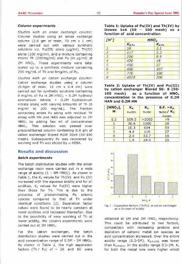
BARC New,'ett" 92 Founder', Day Spedall,"ue 2002
Column experiments
Studies with an anion exchange column:Column studies using an anion exchangecolumn (2.8 gm of resin, 70 em x 1 em)were carried out with various syntheticsolutions viz. pu(m) alone ("g/ml), Th(IV)alone (200 mg/ml), anda mixturecontainingmacro Th (200mg/ml) and Pu (in "g/ml) at2M HNO3. These experiments were laterscaled up to a synthetic mixture containing200 mg/mL of Th and 8mg/mL of Pu.
Studies with an cation exchange column:Cation exchange studies using a column(0.8gm of resin, 10 em x 0.4 em) were
carried out for synthetic solutions containing8 mg/mL of Pu in 2M HNO, + 0.2M hydroxylammonium nitrate + 0.2M hydraziniumnitrate along with varying amounts of Th (8mg/ml to 200 mg/mL). The fractioncontaining entire Pu along with residual Thalong with HN and HAN was adjusted to 2MHNO, by adding few ml of concentrated
HNO3. This solution was passed overpreconditioned column containing 0.8 gm ofcation exchanger Biorad AGW 50x4 (50-100mesh). Subsequently Pu was recovered bywashing and Th was eluted by a-HIBA.
Results and discussion
Batch experiments
The batch distribution studies with the anion
exchange resin were carried out in a wide
range of acidity (1 - 8MHNO,). As shown inTable 1, the Kd values for Th(IV) and Pu (IV)increased with the aqueous acidity and for allacidities, K, values for Pu(IV) were higherthan those for Th. This is due to the
presence of predominating Pu anionicspecies compared to that of Th underidentical conditions [2J. Separation factorvalues were found to be nearly constant atlower acidities and increased thereafter. Due
to the possibility of easy washing of Th atlower acidity, the column experiments werecarried out at 3M HNO,.
For the cation exchanger, the batchdistribution studies were carried out in theacid concentration range of 0.5M - 5M HNO3.As shown in Table 2, the high separationfactors (Th I Pu) of ~ 28 and 60 were
Table 1: Uptake of Pu(lV) and Th(lV) byDowex lx4 (50 - 100 mesh) as afunction of acid concentration
Table 2: Uptake of Th(lV) and Pu(IIl)by cation exchanger Biorad SOx 8 (50-100 mesh) as a function of HNO,concentration in the presence of 0.2MHAN and 0.2M HN
~00
"
[""OJ."
Fig 1 in cation exchanger
obtained at 1M and 2M HNO, respectively.This could be attributed to two factors,competition with increasing protons anddepletion of cationic metal ion species asacid concentration increased. Over the entire
acidity range (0.5-5M), Kd,'c{m) was lowerthan K,.,,{,,). In the acidity range O.S-IM, K,for both the metal ions were higher which
[Wi HNO,KdP" KdT
1 58 3.12 117 5.33 200 8.94 420 185 450 576 450 1077 770 1908 4010 206
[HNO,], Kd. Kd. S.F. -Kd.M p"mn ,""V) T""V'/ Kd.
,0.5 109.5 >1000 >9
1 36.4 1000 282 10.3 604 593 4.4 119 274 2.4 43.7 185 1.4 24.8 18

BARC N,w",Uer 93 Founder', Day Special h.., 2002
demanded large column volume for elutionof both the ions whereas in 3-5M acid range,K, values for both the metal ions were foundto be too low to be held onto the column. 2MHNO, was thus the optimum acidity asKd"""u) is very low (~10) and Kd,o>,'" issufficiently high (~600) with the separationfactor of ~ 60 (Fig. 1).
Column experiments
In view of the low Th(IV) Kd value, high
Pu(IV) Kd value and high separation factor(Pu j Th), it was decided to carry out thecolumn studies using the anion exchanger at3M nitric acid, On the other hand, the low Kd
value of pu(m) and high Kd value of Th(IV)in cation exchange resins prompted us to
carry out the experiments at 2M nitric acid.The sorption of Th and Pu were studiedindividually as well as with a syntheticmixture conforming to the proposed AHWR
scrap composition. The loading of both Thand Pu onto the anion exchange column (2,8gm of resin, 70 em x 1 em) was carried outfrom 3M HNO,. While Th could be washedaway from the column with 3M HNO, itself, itwas required to reduce Pu to pu,. using 0.2MHydrazinium nitrate + 0,2M hydroxylammonium nitrate in 0.5 M HNO,.
!: .0
tJJ; .~ D
1;~ .'J' »
n\
.' "" '"
, Cot'VOlu'me'r
F)g, 2, Pn eMign with OAM HNO,+O.3M HAN+O.3M HN
Based on these principles, the separation ofPu-Th from synthetic solution containing 205mgjmi of Th and 8.1 mgjml of Pu wascarried out in two stages. First stage
involving anion exchange at 3M HNO" Puwas adsorbed strongly whereas Th was
adsorbed very weakly. About 90% of Th waswashed out in 7-8 column volumes leavingentire Pu and residual Th in the column. Both
the metal ions eluted quantitatively withDAM HNO, + 0.3 M HN and HAN in 6 columnvolumes (Fig. 2). This stage helped todeplete the bulk of Th thereby avoiding alarge column capacity and large volume ofthe eluent required in the second stage of
cation exchange, Eluted portion from firststage was adjusted at 2M HNO, containingabout 0,2 M HN + 0.2M HAN and loaded onto
the cation exchange column (0.8gm of resin,10 em x 004 em), Pu was recoveredquantitatively by washing with 8 columnvolumes followed by Th elution in 6 columnvolumes (Fig. 3) using 1M a-HIBA at pH 4.0.
Thus, the cation exchanger methodfacilitated the removal of Pu in the trivalentstate from residual Th.
!:.52
~ 00
~~'"> 00
~'"' >
C~I Vol;'"" 00
Fig.3 The eMion by 1M HIBA at pH=4 (loading"Mion Th)
This way the overall Pu recovery was> 99%while> 98% Th could be recovered whenthe recovered Th were combined from both
the anion exchanger as well as cationexchanger columns, This two-stage columnchromatographic separation method can beused for the separation of Pu and Th fromthe AHWR fuel scrap in nitric acid medium.
Conclusion
Pu-Th could be efficiently separated fromstripped solution by cation exchange methodat the loading conditions of 2M nitricacid containing O,2Mof hydroxyl ammonium

BARC New,]e"" 94 Foond,,', D,y Sp""] "'ne 2002
nitrate as reducing agent and 0.2M ofhydrazinium nitrate as holding reductant. 1Mo-HIBA was found to be an efficient elutingreagent for thorium and had no interferencein the oxalate precipitation. Quantitativerecovery of Pu from the synthetic solutioncontaining 200g/L of Th and 8g/L of Pu wassuccessfully achieved through two stageprocess where anion exchange was followedby cation exchange.
References
1. J. J. Katz, G. T. Seaborg, and L. R.Morss, The chemistry of the actinideelements, second edition, Chapman andHall, New york, (1986) p.p.SSO-S61Plutonium Ion Exchange Process, no7607 (1960)
2.
This paper received the Best Poster award at the 2dh Annual Council of Chemistsheld at Mysore University, Mysore, during October 2001
About the authors ."
Mr L. B. Kumbhare joined Radiochemistry OMslon. BARC, In 1998 aftee obtaining his M.Sc(Chemistry) fcom Nagpuc Unl"",lty and after successfully graduatIng fcom the 41" batch of theB.A.R.C Tcalnlng School. His main ac" of ces"cch Is actinide pactltlonlng branched monoamldes acd dlamldes Mc. Xumbhace has caccled out syntheoes of seveeal such His researchInterest also Indudes Ion exchange sepeeatlon of actinides.
mnfecences
Dc V, X. Manchanda )omed theand fcom the 12'" batch of theIn 1975 and caccled out Po"-OoctocalHis research Interests Include
h lanthacldes and actinides,synthesis of nMel exteactaofs foc
;ed Guide In
the Actinidepublications to his ccadlt

BARC Newsl,"" 95 Foood,,'s Day Spedallssoe 2002
Pilot Plant Experience of Recovery of Rare,Natural Protactinium fromthe Insoluble Muck: Installation andOperation
S. Sethi, P. Anupama and L.M.Gantayet"," & ""m' rechoala9Y OlvisiaoBh,bh, Ataml,
and
M. P. BellaryChemic"~ E0910e,,'09 O"i"aoBh'bh' Atomic ReseM,h Ceotee
Abstract
Introduction
mPa is a recurring nuclide in the ThoriumFuel Cycle. and hence studies related to itsbehavior at various stages, is important tothe future nuclear program in India.
Naturally occurring protactinium (mpa) isone of the rarest elements in the earth crust,and can be found only in the uranium
bearing ore. As its half-life is 32,400yearscompared to its parent mU half-life of3xl0ey, the ratio of protactinium to U is0.34xl0", in the undisturbed geologicalformations [Palshinn et a1.]. In the Indianores the concentration of protactinium isaround 0.2ppb (parts per billion) in Jadugudaare and 0.9ppb in Monazite sand.
In the uranium are processing plants this
element gets fractionated unevenly intovarious streams. Rigorous prospecting for
protactinium in all the streams of the areprocessing plants showed that the richestsource of protactinium is the waste insolublemuck at 5-6.5 ppb (dry basis) of the
monazite processing plant at IRE, Aluva[Anupama et a1. 2001 (a»). As the wasteinsoluble muck is an exit stream from the
IRE Aluva plant, it could be processed forrecovery of mPa without disturbing the plantoperations.
Brief Description of the Process
A process has been developed for recoveryof protactinium from insoluble muck in thebench scale [Anupama et a1. 2001 (b)]. Theprocess is based on selective leaching ofprotactinium from the muck with oxalic acid.The muck contains large quantity of free HCI(30% moisture of 2N HCI strength) andsoluble chloride salts of rare earths and
thorium, which are readily hydrolyzed at
higher pH. Therefore, these have to becarefully removed by HCI wash and then bywater wash. Finally, the free HCI acidcontent in the muck should be reduced to
below a.lN for effective complexing of mpa
by oxalic acid. This step in the process iscalled pretreatment.
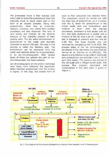
BARC New"eU" 96 Fouod,,'s Day Speda! Issou 2002
The pretreated muck is then leached withoxalic acid to bring the protactinium from theinsoluble muck to liquid oxalic acid in theform of an oxalate complex. Along withprotactinium, other ions as zirconium,niobium, uranium, iron, which form oxalatecomplexes are also dissolved. The bulk ofrare earths and thorium do not dissolvebecause of low solubility product of theiroxalate salts. The dry basis concentration ofprotactinium in the oxalic acid leachateincreases to around 350 ppb. This step in theprocess is called the leaching step. Theprotactinium can be recovered from theoxalic acid leachate either by co-precipitationor by ion-chromatography. After carefulstudy of these two options the path of ion-chromatography has been selected.
Ion chromatography on the anionic exchangeresin being more selective, the separationfactor between protactinium and the co-ionsis higher. In this step, the oxalate form of
HCI(2N)
InsolubleMuck ofMonazitePlant
resin is first converted into chloride form.The conversion should be carried out withthe least loss of protactinium, as it is knownthat the Kd factor for protactinium in themixed oxalic acid and hydrochloric acidmedium is lower. After the chlorideconversion, zirconium is first eluted with 6NHCI, and then protactinium is eluted with amixture of 8N HCIand 0.2N HF. Finally, thebed is stripped of uranium and iron ions by0.2N HCI. The trace fluoride ions areremoved by complexing with O.lN AICI3-Theprocess steps of the ion chromatography,developed in the laboratory are described byVerma et al. [Verma et al.,2001(a)]. Theeluate is precipitated using sodium hydroxideand protactinium concentration now is 10-15ppm (dry basis). This process was proven inthe lab-scale and in 500gm-bench scale. Theprocess flow diagram developed andimplemented in the pilot plant is given inFigure 1.
Make-upOxalic acid
Effluent Oxalic Acid Jand wash (Th, RE)
Elution ofZr, Nb, U &Fe
(2N & O.2N HCI)
Elution of product Pa
(aN HCI + O.2N HF)
Regenerationeffluent
Fig " Flowdl'g"m focthepcoee" of pco"etlnlum "cover; fcom Insoluble muck of Munozlte pl,nt

BARCN,w,lett.. 97 Fo.od..', Day Special I"., 2002
Plant Design Considerations
Radioactive solid handling
The ground monazite comes in the averagesize of Sum. Handling of these sub micronsize particles In large tonnage, andseparating the liquid and solid with negligiblecarryover of solid posed a challenge. Manualhandling of slurry, cake and solutions couldexpose the workers to radioactivity dose andat the same time high degree ofsophisticated automation was not warrantedfor a campaign type of operation. This wastaken care of in the proper equipmentselection and suitable plant layout. A
I
perspective view of the plant is given inFigure 2.
The plant layout was so designed thatI gravity flow of the materials was possible to
a large extent. Filtration equipment, wherenormally filter press is used, involvesprolonged manual handling of radioactive
solids. Drum filters would be too expensive.So a vacuum Nutsehe filter was selected.
Effluent control
Reducing radioactive effluent was One of theprime considerations in the plant. Forcreating vacuum, the normally preferredwater-ring pump was again avoided, as itwould generate large quantity of low activecooling water effluent spread over a largearea of piping, and cooling tower basin.Hence a rotary piston pump, which has ahigh tolerance to air and moisture, wasselected. A suitable trap at the inlet trappedand removed moisture and a homemademist filter, made of high performancedistillation packing removed the oil vapourfrom the exhaust air. All the other liquideffluent is neutralized in a rubber lined tank.The slurry is assessed for radioactivity andthen sent to waste management division, fordisposal as per procedure.
-".,
Fig.> , Pe""ective view of"'Pa recove,,! plant
'"

BARCN,w","" 98 Found,,', Day Sp,,;al Issue 2002
Materials of construction
Protactinium is readily hydrolyzed and knownto stick to the equipment walls. It would bevery difficult to recover 3mg of protactiniumfrom !Te quantity of solid, and from 4m' ofliquid unless the material of construction andthe flow medium transporting protactiniumare carefully selected. The agitated tankswere made of polypropylene lined FRP, aswas the ion-exchange column [bothmanufactured by Mis PlastochemFabrication, Trombay, Mumbai-88]. TheNutsche filter was made of FRP[manufactured by Mis PlastochemFabrication, Trombay, Mumbai-88], with the
wetted surface
Table 1: Design Considerations for Ion Chromatography Column coated with./ polyvinyl-ester for
higher resistanceagainst strong acidmixtures. For liquidtransfer, reinforcedpolythene hoseswere used. Teflonlined diaphragmvalves with
PP linesFRP ( to withstand4 kg pressure) polypropylene bodywere used. The ballvalves did notwithstand the weardue to the abrasivefine solids.Polypropylene clothof nominal pore sizewas selected as
filter medium. For easier filtration, celluloseacetate was used as filter aid wherever acarrier was necessary to remove very smallquantities of valuable solid from the liquid.The filter aid was evaluated in the laboratoryand was found not to adsorb protactinium-hydroxide. It was found suitable and wasused. Polypropylene pumps [manufacturedby Mis Antico Ltd., Mumbai] with teflongland packing or ceramic mechanical shaftseal could handle the acids of the plant withease.
Ion exchange equipment
As the ratio of the loading and eluate cycleswas 10:1, one ion exchange column withmore plumbing for operational flexibility waspreferred to two standard ion exchangecolumns. Pre-concentration being one of theprime objectives in the ion exchange resin,the free board volume over the resin wasreduced drastically compared to theconventional ones, so as to allow only forresin shrinkage in oxalate form andexpansion of the bed, in chloride andhydroxide form. The design considerationsfor ion exchange separation are summarisedin Table 1.
Design Parameters
Loading to Elution batch ratio
Resin Bed Height (GS 300)Resin Bed Diameter
Loading. WashIng & Elution Rates
Turbidity of Feed solulion0.5;.m)
Compatible MaC
10-11 batch Leaching/Elution
1.2to 1.5 m
385 mm
6.0 m'lm'/h.
< 3 NTU (using micro filter 10, 1.0 &
Other Considerations
Purity of reagents
DM water was used at all stages of the IonChromatography. Similarly, the HCI used hadto be pure. Instead of purchasing analyticalgrade HCI at prohibitive cost, HCI waspurified in the pilot plant, economically in a
~13litre FFIP (supplied by Mis. Ion ExchangeIndia Ltd.) resin bed in a FRP column. The
technical grade HCI from the storage tankwas decanted into the resin bed at a
controlled flowrate and the purified HCIcollected in carbuoys or process tanks. Thefumes of HCI were contained by usingcovered equipment, and covering allopenings with wet PP cloth.
The stirrers for 2N HCI were rubber-lined,'
whereas for oxalic acid, 55 stirrer with PVCtaping was sufficient to withstand one yearlong operation. Air agitation though
BARC New,k"" 99 Found,,', Day Spedal hm 2002
preferred for not breaking the flocs, couldnot be used to avoid the radioactive aerosolsin the environment.Measurements
Magnetic float in Teflon rotameter was usedfor the measurement of the flow in the Ionexchange column. At all the stages, tankswere volume calibrated with water andpainted. Calibrated volume measurementwith stopwatch gave an accurate measure offlow at all stages. Hydrometer and pH paperswere extensively used to measure thespecific gravity of the liquid and the pHrespectively.
Quality control
The strength of the decanted HCIand waterwashes was determined by titration in theplant by the operator. Suitable procedureswere devised in the lab to take care of rareearths chlorides andthorium chloride,while titrating forfree HCI. Thestrength of oxalicacid was determinedby titration withKMnO, in presencesulphuric acid.
Process
Implementationin the Plant
was slow. It was then decided to resort tosedimentation, and sludge dewatering, whichcan be enhanced by using polyelectrolyteflocculant. Several flocculants were tried forthe 2N slurry and 852 Rishabh (852R)[obtained from Mis. Rishabh Metals andChemicals Ltd., Mumbai-20] was foundsuitable for use at BOppm dosage. Theflocculant was prepared at 0.2%concentration, for better mixing. Theconcentration of 80ppm was optimum to givehard flocs, which remained stable duringsubsequent water washes.
The stirrer used was selected formultipurpose use of the 0.8m3 capacity tank[Figure 3]. A small propeller placed at aninclined angle served the purpose ofproviding minimum shear in the bulk of thefluid and thorough mixing within 45 sec. Theconical bottom of the tank was given a slope
Pretreatment
500gm scale tests inthe lab, revealedthat, thoroughmixing is necessaryafter loosening ofthe cake. The timetaken for dissolution of soluble salts isminimal. At times, the reduction in weightafter dissolution was as high as 30%, whichwas attributed to the higher content ofsoluble salts due to continued attack by thefree acid in the moisture. The mainconsiderations in the scale-up of the stepwere solid-liquid separation and dilution ofthe acid in every wash stage. The vacuumfiltration with 5"m particle size solid slurry
Flg.3, Agltotlon tonk used formpa "covertP!an!
of 30', to facilitate easy removal of thesludge.
For decantation, an adjustable heightstrainer was provided. The decantation ratecould be controlled to avoid re-agitation ofthe sludge. Up to 80% of the liquid addedcould be decanted, which reduced therequirement of dilution, and consequentlythe total volumeof the effluent.
BARC New,'e"" 100 Fonnd,,', Day Speda' ["ne 2002
Filtration of pretreated sludge
The Nutsche filter is mainly used for the[iltration of the decanted volume, A layer ofcoarse solids is first formed, to act like filteraid for deep bed filtration for the nearly cleardecant.
The sludge is lowered onto the Nutsche filterfor final dewatering and drying (when itcracks). Based on the lab scale data a 1.2mdiameter Nutsche with an available "p of 460
to 600 mm Hg was found suitable. The cakeis removed manually using wooden ladlesinto polythene-lined drums to store for thenext step of operation. The vacuum iscreated by 100m3jh rotary piston pumps[manufactured by Mjs H. K. Industries,Kalina, Mumbai-98] with an ultimate vacuumof 1 mbar [Figure 4]. The first vacuum trapwas an expansion tank, where the moisturecondenses, and is drained periodically. Thepump exhaust trap is also periodicailydrained to remove oil-water emulsion. Theoil consumption was two litres per 100 hoursof operation.
filtration characteristics. 40 ppm of 852R isthe optimum concentration of ftocculant. Thefiltration arrangement is similar to thepretreatment step. Here a wash is given with0.5N oxalic acid to recover the leachate fromthe cake. The volume of oxalic acid used is
the same as the pore volume of the cake.
Loading of ion exchange column
The clarity of the oxalic acid is veryimportant as oxides of zirconium, niobiumand iron can adsorb protactinium after theoxalic acid is washed out in the column.Moreover, the column can get silted. Theturbidity was measured by nebulometer andfound to be 9 NTU. A micro filter of around10"m, followed by 1.0"m & 0.5"m cartridgewas used for the oxalic acid loading step,which reduced the turbidity below 3 NTU.
The loading rate determined at the lab was6.0 m3jm'jh. The column was designed tohave 1.2m to 1.5m bed height (lab bedheight was around 0.8m) and a volume forholding 10-11 batches of leachate solution.
The effluent oxalic acidwas quite clear. Initially,in the first bed volume,the oxalic acid strengthdropped from 2N to1.1N, because of theconversion of the ion
exchange resin fromchloride form to oxalateform. The effluent oxalicacid was held in anintermediate tank and
returned for leachingafter adjusting theconcentration to 2N. Inthe normal batches the
oxalic acid strengthreduces to around 1.6Nbecause of its reactionwith rare earths and
thorium in the pre-Leaching
FigA, V,wum st,tion used foe mp, recoy",y p/,nt
treated cake.
Demineralised Water (DM) water wash600 litres of 1M oxalic acid is prepared in thetank. 150 kg of weighed cake is loweredwhile stirring is on. The stirring time isaround 2'1, hrs. At the end of the extractioncycle the solids are flocculated for better
The oxalic acid is washed to 0.05N by 3 bedvolumes (BV) of demineralised water wash.There is no loss of protactinium in this step.
BARC N,w",Uer 101 Fou.der', Day Sp,dalT"., 2002
HCI conversion
Initially 8N HCI and 7N HCI was used for theconversion of the bed. During the operationonce due to pump failure, the HCI remainedin the column, leading to standing of HCI-oxalic mixture in the column. This led to
substantial loss (12% loss of protactinium)from the column. The 7N HCI wash isfollowed by 6N wash to remove zirconium.During this step a small quantity ofprotactinium is lost. Niobium is also elutedalong with zirconium. The details of theelution steps are discussed by Verma et al.[2001 (b)].
Elution
For elution of protactinium 8N HCI & 0.2N HFeluent was passed through the column at avery slow rate of 1.0 m3/m'/h, in order toreduce the tailing and the consumption ofhigh molarity acid. Lower consumption ofeluate means, less requirement of NaaH forneutralisation. 2.5 BV of eluate was
considered adequate. The last 0.5 BV ofeluate containing lower quantity of Pa wasrecycled as the first BV of eluent for the nextstage. A typical elution curve for the plantcolumn is shown in Figure 5.
'<G ,. 'OM,,"O' , "'ARAT'OO rn "Oll""/Gs,"",",o "'-O"'H. 1100MM.'lA, ",'"
10
:::.'"f,~ 4
-0.."".-""'M"o",wrn".,,"-'M HC'""'"-'."'H" "","0-'M.HC'.O.'"" "0""0
'ff'oontjTh,REE."'.1
'eo,
10 20 JO 40 50
Cumo'.'","'" 0"0.O"Vo'om.."R..'"
There was always 5-10% loss in the Tonexchange steps. However, since the gel resincontained negligible quantity of hydrolyzedprotactinium, it is expected that this quantityof protactinium would be adhering to thewalls of the pipes and equipment.
Neutralisation
The eluent is neutralised, and filtered. Thehydroxide containing 16ppm of protactiniumwas washed with demineralised water andthen dissolved in 25litre of 2N oxalic acid for
the next stage of Ion chromatography in thesame column.
Radiological andProceduresThe contact radiation field in the raw muck
barrels (150kg) is typically 15mR/h (milliroentgen per hour). The process tanks gavea contact radiation field of 1mR/h. Theeffluent slurry had an alpha activity of 50-60Bq/ml. Although these fields are low, theprescribed radiation safety rules werecomplied with. The workers in the plant woreTLD badges. After a few monthlyassessments of the badges, which showed nil
dosage, the badges werethen counted everyquarter. Annual dosereceived by each workerwas also assessed and therecords were maintained.
The process vessel walls,the floor and structures of
the plant were cleanedeveryday to remove slurrysplashes, which onstanding could g,veavoidable surface activity.Personnel safety gears,such as, facemasks, PVCgloves, aprons, safetyshoes were mandatory forany work in the plant. Theoperators were providedrigorous training tomaintain high safetystandards.
Other Safety
'1(Z',Nbl
"""1"1
IRo,onw""",..
150 lit,e GS-300 bed (I"9th . 1100 mm,
60
(;9.5.

BARC New","'" 102 Feend,,'s Dey Speciall"ne 2002
t1"blji!i2: ProductionFigures
(15 $~ptel11ber 2000 -18 December 2001)
Batch size Pretreatment
Leaching
No. ofpat~~es .
aTotal Quantity
Iprocessed '.SummaryThe plantwas operated for 70 hours a weekon the average. The production figures aregiven in Table 2. For the first time a materialavailable in 5 ppb in the source has beenextracted on this scale. The process of oxalicacid leaching and ion-chromatography hasnot so far been used elsewhere forprotactinium recovery. The methodologyfollowed for operation, quality control, andbook keeping of product in every stream, isuseful to any team trying to separate andpurify valuable and rare minerals.Systematic establishment of the procedures,in close collaboration with the chemistrylaboratory, has helped in maintainingefficiency and consistency. Effectiveradioactive effluent management procedurecould be established. Conscious effort by theentire team resulted in nil incident safetyrecord. The spin-off processes resulting fromthe pilot plant experiences are mineralisationof the monazite processing plant [Sethi et al.2001], and decontamination of zirconium/niobium from other elements when it Is
200kg insoluble muck
150kg insoluble muck
if;
->;
btained
recycledfrom the nuclear reactor [Gantayetet al. 2001].
Acknowledgements
The authors acknowledge the contribution ofMs. Manisha Gupta, Mr Dileep Kumar andMr K. K. Mishra, LPTD, BARC, for the help in
the fabrication and testing of some of thecomponents/equipment of the pilot plant andM/s. IRE Ltd. for the supply of the insolublemuck.
References
1. Palshin, E.; 5., Myasoedov, B. F.; andDavydov, A., V., "Analytical Chemistry ofProtactinium", Chapter IV, Ann-HumpreyScience Publishers, 1970.Anupama, P.; Gantayet, L. M.; Verma,R.; Parthasarathy, R.; Anil Kumar,S.;Dingankar, M. V.; Ghosh, S. K.; andPatra, R. N., "Prospectingfor natural"'Pa in India" BARCReport No. BARC-2001/E/020,2001(a).
2.

BARC New,lett" 103 Fonnd,,', Day Special I"ne 2002
3. Anupama P.; Verma, R.; Parthasarathy,R.; Gantayet, L. M.; Anil Kumar,S.;Sethi,S.; Gupta, Manisha; Sadhukhan,5.; Bellary, M. P. and Patra R. N.,"Development of a Process for Recoveryand Pre-concentration of Protactinium-231: From the Waste Insoluble Muck ofthe Indian Rare Earth Plant by selectiveLeaching and Co-precipitation onCarrier", pp 60, Technical Abstracts,CHEMCON-2001.
4. Verma, R.; Anupama P.; Bellary, M. P.and Gantayet, L. M., "Development of aprocess for separation of protactiniumfrom REE,Thorium, and other metal ionsby ion chromatography", SPAREI-2001,August 17-19, Munnar, Kerala, 2001(a).
5. Verma, R.; Gantayet, L. M;Anupama P.;Sethi, S. and Bellary, M. P.,"Development of a High Selectivityprocess for separation of Protactinium-
6.
231 from rare earths, thorium, uraniumand other metal ions by IonChromatography and its implementationin the Protactinium recovery plant", pp42, Technical Abstracts, CHEMCON-2001.Sethi,S.; Anupama P.; Gantayet, L. Mand Nair V. R., "Process for Washing andMineralisation of the insoluble muck ofRare-earth plant for easy disposal- Somestudies and implementation at Plantscale", SPAREI-2001, August 17-19,Munnar, Kerala, 2001.Gantayet, L. M.; Verma, R.; AnupamaP.; Sethi,S.; Sudersanan, M.; Sahoo, K.C. and Venugopal V., "Development of aprocess for removal of actinides andother impurities from recycledzirconium", INS-2001, October, 10-12,at CAT,Indore, 2001.
7.
This paper was adjudged as the First Best paper in the oral presentation in thetechnical main session "Industrial Process" at CHEMCON-2001 symposium heldat Central Lellther Research Institute, Chennai, during December 19-22, 2001
About the authors ...
II
II
Dr LM. Gantayet graduated fcom
. ChemKa! Engmeenng. He ha,,'.'
'n 1974. afterfocthe
In

BARC Newsle".. 104 Found..'s Day Speeiallssoe ZooZ
Development of a High Selectivity Processfor Separation of Protactinium- 231 fromRare Earths, Thorium, Uranium and OtherMetal Ions by Ion Chromatography and itsImplementation in the ProtactiniumRecovery Plant
R. VermaAnalytiCal Chem"t" DivisionBhabha Atomic -e,eaceh Centee
L.M.Gantayet, P. Anupama and S. SethiI."ee' PI"ma TechnologyoM,ionBhabha Atom;c-e,.,aceh Centre
and
M. p, BellaryChemical Enginee.ieg OivlSioeBhabha Atom;c _e,wch Centee
Abstract
"'Po i, available at a concan"a,;on of around 350ppb (parts pee billion) in the oxalic aCid leachate of theprotactinium cecove'1' plant. An ion exchange proce" ha, been developed to, pu',"caOon of protactiniumfrom iron, u,anium, zi,conium, niobium and olh., co-ion, by ion exchange. An anionic exchange lesin G5-300 (M/,. IEL LId.) ho> been used fo, the trials. The ion exchange proce" wo> d"eloped in diffelentstage" labolOto'1' scale with 0.01.0.03dm' lesin bed, indust,ial bench scale with 0.375dm' lesin bed andimplemented in the plant using a bed of 125-150dm' GS-300 lesin bed. "Z" "Nb, mPa tr"elS wele usedto detelmine the mo,.ment of these ions in the bed. "'Po at a concentralion of around 10ppm could beobtained by this p,oca". The Ion -exchange proce" development and its implemenlaOon in the plant alediscu"ed in th" popel.
Introduction
"'Pa, one of the rarest elements is ofinterest to the thorium fuel cycle studies ofthe Indian Nuclear power program, "'Paoccurs at 5-6,5 parts per billion (ppb)concentration in the waste insoluble muck ofthe Monazite Processing Plant of Indian RareEarths at Aluva, A process for recovery ofprotactinium from the insoluble muck byselective leaching by oxalic acid, to arrive ata concentration of around 350ppb is reportedby Anupama et aI., 2001.
Further purification of protactinium fromiron, uranium, zirconium, niobium, thorium,titanium and rare earths was proposed to be
done by the high selectivity ion exchange(I-X) process, Earlier workers have used I-Xprocess to purify protactinium in highmolarity HCI using strong anion exchangeresin Dowex IX8 [Collins et aI., 1962, Krausset al., 1958, Kluge et aI., 198O, Palshln etaI., 1970], The present process is based onthe oxalic acid leachate, which containsaround 350ppb protactinium. The ionexchange process was developed in 3stages, namely, lab scale trials using bedvolumes of 0.01-0,O3dm', industrial benchscale trials using a bed volume of OAdm3with column height of 750mm, and finally inthe plant using a bed of 125-150dm', Thetypical anlysis of oxalic acid leachate and the

BARCN,w,I,"" 105 Foond,,', Day Sp,dal Iss., 2002-DATA OBTAINED
!Oxalic acid I HCI6N I7N HCI9N HCI + O.2N HCI
'I HCI + oxalic mixtureO.2N HCII DM waterDM water
PhysiGocGhemical data
). Swelling/shrinkage in various mediums
»BuoyanGY effects with reagents
ment - --- - -- ~
O.O1-O.03dm'o.4dm'. 76cmheight125-15Odm'.1.5m hI. column .
- -", JFig. 1 Pocific",wn by ion 'xchange ,Mion chcomatowaphy
distribution coefficient of the variouselements in oxalic acid and 6N HCI are
presented in Tables l(a) and l(b).
Experimental Work
Laboratory scale trials
The Indian resin GS-300 (manufactured byMis. Ion Exchange India Ltd.) was chosen for
trials, after establishing the equivalence withDowex 1X8. The lab scale trials were
conducted to obtain preliminary data on (a)
maximum loading capacity for protactinium,and conditions for (b) selective elution of",conium, niobium, (c) elution of
pmtactinium, (d) stripping, (e) regenerationof the bed etc. The physico-chemical data
such as, swelling and shrinkage in variousmediums, buoyancy effect with reagents
>1
,. >10'
Nb >10'
120
U >10' 200
Fo >10'
::':""""00Th low
REE low 000""""00
BARC Newslett« 106 Foond«'s Day Special Issue 2002
were also determined. For protactiniumelution, several eluants were tried:hydrochloric acid and dilute hydrofluoric acidmixture, hydrochloric and oxalic acid mixtureat different normalities. Lesser number ofbed volumes was required lor elution ofprotactinium with HCI and HF mixture. 9NHCI and 0.2N HF mixture was used as eluant
for protactinium in all the subsequentexperiments. The details of these experi-ments have been reported by Verma et ai.,2001. A summary of the data obtained in thelab scale trials and the stages ofdevelopment are given in Figure 1.
Industrial bench scale trials
The industrial bench scale column was a
glass column of 25mm diameter, 750mmlength containing 0.375dm' GS-300 resin(0.3 - 1.0mm size range). The oxalicleachant from the plant was used as feedand the process data for the following sixsteps of the ion exchange process wereobtained. The integrated flow in terms of bedvolumes was used as a parameter todesignate each step of operation. Theschematic of the industrial bench scale
olumn is presented in Figure 2.
Oxalic acid~Ieachat. from Parecovery plant
Saturation:Fe: 40BYSCo-ions: 100BYs
complex. The major fractions of anioniccomplexes were those of iron, zirconium,niobium, uranium ete. present to theextent of 2-3gpl (measured in terms ofprecipitated and calcined oxides). Thesaturation with respect to protactiniumwas reached in 100 bed volumes (BVs)[Verma et ai., 2001]. The bed wassaturated with respect to iron in around40 bed volumes. For the experiments ofthe subsequent steps, 40 BVs of thefeed oxalic acid was loaded.
2. Washing of the bed: To prevent the lossof protactinium, a demineralised waterwash was introduced before elution ofzirconium with hydrochloric acid. Thisstep diluted the oxalic acid and reducedthe loss of "'Pa in the subsequent step.
3. Selective elution of zirconium and loss of"'Pa: The selective elution of zirconium
with 6-7N HCI was based on relativelylow Kd (distribution coefficient) factor ofzirconium. As Kd of protactinium is alsolower, the loss could be reduced byfaster elution velocity. It is also knownfrom lab trials that a mixture of oxalicand hydrochloric acid reduced the Kd forprotactinium further. Therefore,
maintaining rate of flowfor the first BV of 6-7N
HCI was very important.The movement of
protactinium, zirconium,and niobium was
determined by using"'Pa, 95Zr, and 95Nbtracers respectively.Uranium and iron weredetermined by chemicalanalysis. The elutiondata presented in Table2 shows that a largeproportion of Nb is alsoeluted with Zr.
4. Elution of protactinium:The elution of "'Pa wasdone with 8N HCI and
0.2N NH,F. In the earlier runs, 9N HCIand 0.2N HF was used, but as thissolution made the resin slightly buoyant,SN HCI instead of 9N HCI was used in
this run. Solid NH,F was used instead of
Fig. 2. Schemotlc of mdo",I,1 ben,h >edle ion-ex,h,ngecelomn
1. Breakthrough with respect to "'Pa: Thefeed oxalic acid contained 350ppb ofprotactinium in the form of an anionic

BARC Newslett" 107 Found,,', Day Speelm Issue 2002
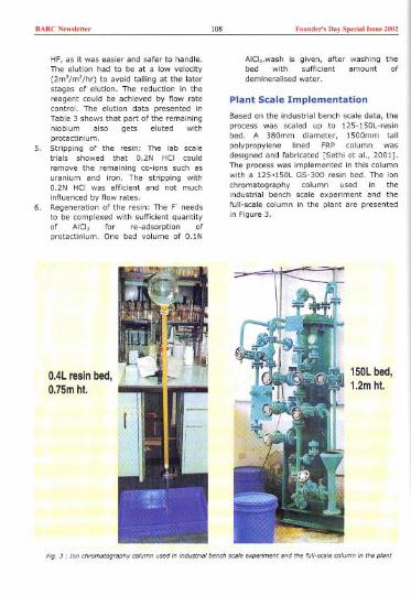
BARC New""t" 108 Faaad,,', Day Speda! '.."e 2002
5.
HF. as it was easier and safer to handle.The elution had to be at a low velocity(2m3/m'/hr) to avoid tailing at the laterstages of elution. The reduction in thereagent could be achieved by flow ratecontrol. The elution data presented inTable 3 shows that part of the remainingniobium also gets eluted withprotactinium.Stripping of the resin: The lab scaletrials showed that 0.2N HCI could
remove the remaining co-ions such asuranium and iron. The stripping with0.2N HCI was efficient and not much
influenced by flow rates.Regeneration of the resin: The F' needsto be complexed with sufficient quantityof AICI3 for re-adsorption ofprotactinium. One bed volume of O.IN
6.
O.4L resin bed,O.75m hI.
AICl3.wash is given. after washing thebed with sufficient amount ofdemlneralised water.
Plant Scale Implementation
Based on the industrial bench scale data. theprocess was scaled up to 125-150L-resinbed. A 380mm diameter, 1500mm tall
polypropylene lined FRP column wasdesigned and fabricated [Sethi et al., 2001].The process was implemented in this columnwith a 125,150L GS-300 resin bed. The ion
chromatography column used in theindustrial bench scale experiment and thefull-scale column in the plant are presentedin Figure 3.
150Lbed,102mhI.
FIg. 3 , Ion chromatog"phy column used In IndustrIal bench scale experIment and the full-scale column In the plant

BARCN,w""'" 109 Foond,,', D,y Sped,! "m, 2002
1. Loading: 40BVs of feed oxalic acidsolution is loaded into the column ataround 6.3m3jm2jhour.
2. Recycle of effluent: The oxalic acideffluent, which is free from the anioniccomplexes of Pa, Zr, Nb, U, Fe, etc., isadjusted to 2N strength and recycled tothe leaching section of the plant forprotactinium leaching from pre-treatedinsoluble muck.
3. Washing of bed: 3BVs of demineralisedwater wash is given at around 12.6m3jm'jhour to reduce the oxalic acidconcemration. During the demineralisedwater wash, the oxalic acidconcentration was measured todetermine the axial mixingjdispersion ofthe liquid, which is passed through thebed. The data is presented in Table 4.Although the free pore volume in thebed is only 40%, it took nearly three bedvolumes (150L bed) to reduce theconcentration of oxalic acid in theeffluent from 1.6N to 0.07N.
Table 4: Axial mixing studies in thePlant column
1. Column Dimension" 380mm diametee,1500mm length
2. Resin bed volume: ~1501itce = 1 bed volume(BV)
3. Demineralised water wash: 3 BVs
4. Selective elution of zirconium, niobiumand stripping of the bed: 2N, 6N, 7N, 8NHCIeluant was used in different batchesfor selective elution of zirconium,niobium and other co-ions. The eluatesolutions were collected in fractions andthe total oxide was determined in thefractions by hydroxide precipitation andcalcination of hydroxide. The oxidecontent was used as a parameter to ratethe effectiveness of the eluate in
removing impurities. 2N HCI couldconvert the resin bed to cr form andelute most of the co-ions with least lossof protactinium. Further, the strippingstep of 0.2N HCIwas scheduled beforethe elution of protactinium to removeniobium and other co-ions. The 0.2N HCIsolution was recycled till it was saturatedwith co-ions. This reduced theconsumption of acid. This procedure didnot reduce the impurity content ofprotactinium in the eluate, but reducedthe loss of protactinium in the 2N HCIstep.
5. Selective elution of "'Pa: It could bedone with less than 2BVs of 8N HCIand0.2N HF mixture. As HF was readilyavailable, it was used instead of NH,F.The "'Pa concentration in the first BVofeluate is low. The subsequent 1.5BVs ofeluate eluted around 90-92% of theprotactinium. This eluate contained "'Paat around. 4-15ppm dry basisconcentration with major impurities ofzirconium and niobium.
5. Neutralisation of eluate: The eluate isneutralised with sodium hydroxide, theprecipitate is filtered, washed withdemineralised water and redissolved in asmaller volume of 2N oxalic acid for thenext stage of purification using the sameresin bed.
Summary
A new process for purification of "'Pa fromrare earths, thorium, zirconium, niobium,uranium, iron by ion chromatography inoxalic acid medium has been developed andsuccessfully implemented in a pilot plantscale. The GS-300 anion exchange resin isquite suitable for this process. Thepurification of protactinium with respect toother dissolved co-ions is possible with 2NHCI, which saved considerable amount ofreagents. However, if zirconium has to becollected separately the 5N HCIwash will berequired. As a spin-off, a process forpurifying zirconium was also established[Gantayet et aI., 2001].
Further work is aimed at establishing thestability of the resin on long-term operation,
Bed volumes of Concentration ofeffluent collected C,O/- (NJ0.0 1.60
0.5 1.591.0 0.981.5 0.392.0 0.122.5 0.103.0 0.07

BARC News""" 110 Fouud,,'s Day Special Issue 2002
and improving separation factors by usinglarger column lengths, and optimum flowrates.
Acknowledgements
The authors acknowledge Mr Anil Kumar and
Ms Narayani, Radiation Safety and SystemsDivision (RSSD), BARC, for counting thesamples by gamma spectrometry. Theauthors thank Head, Laser & Plasma
Technology Division, Head,' AnalyticalChemistry Division, Head, Chemical
Engineering Division and Head, RSSD, BARC,for supporting this work.
References
1. Anupama P., R. Verma, R. Parthasarathy,L.M. Gantayet, S. Anil Kumar, S. Sethi,Manisha Gupta, S. Sadhukhan, M. P.Bellary, R. N. Patra, "Development of aProcess for Recovery and Pre-concentration of Protactinium-231: Fromthe Waste Insoluble Muck of the Indian
Rare Earth Plant by selective Leachingand Co-precipitation on Carrier", pp60,Technical Abstracts, CHEMCON-2001.
2. Collins, D., A., Hillary, J., J., Nairn, J., S.
and Phillips, G., M., "The developmentand application of a process for therecovery of over 100g of Protactinium-231 from a uranium refinery wastematerial", Journal of Inorganic NuclearChemistry, 24, pp 441-459, 1962.
3. K. A. Krauss and F. Nelson, Oak RidgeLaboratory, "Anion Exchange Studies ofFission Products", Symposium on IonExchange and Chromatography in Anal.Chemistry, ASTM No. 195, Philadelphia,1958.
4. Kluge and K. H. Lieser, "Separation ofThorium, Protactinium and Uranium byIon Exchange and Extraction",Radiochimica acta 27, 161-171, 1980
5. L. M. Gantayet, R. Verma, Anupama P.,S. Sethi, M. Sudersanan, K. C. Sahoo, V.Venugopal, "Development of a processfor removal of actinides and otherimpurities from recycled zirconium", INS-2001, October, 10-12, at CAT,Indore.
6. Palshin, E., S., Myasoedov, B. F., andDavydov, A., V., "Analytical Chemistry ofProtactinium", Ann-Humprey SciencePublishers, 1970.
7. R. Verma, Anupama P., M. P. Bellary, andL. M. Gantayet, "Development of aprocess for separation of protactiniumfrom rare-earth elements, thorium andother metal ions by ion chromatography",SPAREr-2001, August 17-19, Munnar,Kerala.
8. S. Sethi, Anupama P., L. M. Gantayet andM. P. Bellary, "Pilot Plant experience ofprotactinium recovery from the insolublemuck: Installation and Operation ", pp42, Technical Abstracts, CHEMCON-2001.
This paper was lIdjudged lIS the Secand Best paper in the poster presentation ofposter-main session "Industrial Process," I/t CHEMCON-2001 symposium held atCent",l Lel/ther Research Institute, Chennai, during December 19-22,2001
About the authors ...
Dr Rakesh Verma waduated '.om BARC Tcoining School (Chemiotcy) in 1983 ,nd jomed the AnelvticalChemi,tcy DiYi,ion. He i, working m the field of "tivetion enelysis.

BARC New,'e"" III Found,,', Day Speda! .".e 2002
D,L. M.Chemical
m"'<onII
..
.
....
.. '."i.' :
I
BE
I
M,M.P.

BARC New,le"" Il2 Found,,', Day Spedal b,ne 2002
Indigenously Developed LiF: Mg, CU, PThermoluminescent Phosphor forRadiation Dosimetric Applications5.5. Shinder B.5.Dhabekar and B.C.Bhatt
Phy,i" ,od Adv"ocy Divi,iooRe"",h Ceotee
Abstract
,nd ti"ue "F.'Mg,Cu,PTheemolumin,"cen'The TL of thi, pho,ph" i, about 1.5 time' tpeak mea>u.emenl>. It TL emi"ion band amund 370 nm It, do>e -". up to Gy. Reu,ability >tud, that it, "n,itivity do," not deccca" even aftee 10
Annealing tempeeatu.e
Introduction
Nakajima et al (1978) .epo.ted for the firsttime In 1978, the preparation ofLiF: Mg,Cu,P, a highly sensitive and nearlytissue equivalent TL phosphor. Thereaftermany workers (Wu et al 1984, WangShoushan 1988, Azarin et al 1989, Horowitzet al 1990, Kolotilin et al 1993, Zha et al
1993) prepared this phosphor in theirlaboratories following different proceduresand studied in detail its characteristics. It is
worth noting that unlike CaSO,:Dy(Yamashita et al 1968, 1971, Ayyangar et al1974, Azoc;n 1984), none of the laboratoriesreported to have used the same
preparation procedure. By manipulation ofdopant concentration Horowitz and Horowitz(1992) could achieve the TL sensitivity about35 times as compared to that of TLD-100.Wang Shoushan (1988) has also studiedextensively the effect of concentrations of
M9, Cu, P on the sensitivity and glow curvestructure of LiF:Mg,Cu,P and concluded that
Mg and P concentration influences theheight and width of 220 'c glow peakwhereas concentration of Cu influences not
only 220 'c and 250 °C peak but also theintensity of 110'C peak. As per their
investigation, the optimum concentrationwas found to be 0.2 mol % MgF" 0.0046mol % CuF, and 1.90 mol % (NH,)H,PO,.Patil and Moharil (1995) showed that
LiF:Mg,Cu,P could be made using simpleprocedure which did not involve a use ofnitrogen atmosphere.
In the present paper, the preparat;onprocedure and characteristics of LiF:Mg,Cu,PTL phosphor prepared indigenously inBARC are described and compared with thatof TLD100-H.
Materials and Methods
Commercially available LR grade LiF was
purified by vacuum dist;;lation method(Muralidhar Rao 1974), Appropriatequant;t;es of purified UF and dopants Mg, Cuand P in the form of MgF" CuCI,.2H,O and
(NH,)H,PO, respectively were mixedthoroughly. The mixture was melted in aplatinum crucible at 960°C ;n a furnace forfifteen minutes and then cooled rapidly to
room temperature, The polycrystallinephosphor thus obta;ned was ground topowder (74-210 microns). Several suchbatches were prepared by vary;ng the
dopant concentrations. The batch havinghighest TL output was chosen to study itssensitivity and other TL characteristics incomparison with Harshaw TLD -100H.
A locally made TL reader having EMI 95248
photomultiplier (5-11 response) as adetector was used for taking the TLmeasurements,. Glow curves were recorded

BARCN",,',"" 113 Found,,', Day Sp,cial I"uo 2002
using linear heating rate of 10~C/s. Foroptimisation of annealing temperature, virginphosphor samples were annealed at varioustemperatures in the range 240'C-320'C for10 minutes~ Peak height of 210'C glow peakwas recorded after a test dose of 0.1 Gy. Forgamma dose. vs .TL response, phosphorsamples from the same batch wereirradiated with Co . 60 gamma rays from0.01 to 10' Gy~
Reusability studies were carried out for 10cycles of reuse by adopting two differentprocedures:
Procedure # 1
All the 10 samples (30 mg each) were firstannealed at 280'C for 10 minutes, irradiated
to a test gamma dose (O~OlGy) and thenreadout by holding the temperature at 280'Cfor 10 seconds. After reading all thesamples, one of the samples was removedfrom the process and marked as "cycle 1'~This was repeated for ten cycles.
Procedure #2
The above process was repeated except thatinstead of pre.annealing at 280'C for 10minutes, pre.annealing was done at 240'Cfor 10 minutes and the samples were alsoreadout holding the temperature at 240C for10 seconds~
TL emission spectra were recorded on anindigenously made TL emission spectrometerusing a locally made monochromator (CELIndia)~ 1 nm slit was used for recording theTL emission spectra~
Results
During preparation of LiF:Mg,Cu, P, onlyfreshly distilled LiF powder was used as itobserved that it gave better reprodu.cibility,
Glow curve
Figure 1 shows the glow curves of virginLiF: Mg,Cu,P (BARe) phosphor prepared inthis laboratory and Harshaw TLD 100.Hafter a test gamma dose of 0,1 Gy. Both thephosphors have similar glow curves withmain dosimetric peak at about 210'c. Outof various batches prepared by varying
§
i"-
f~
TLo.100H
100 200 300
T,mpocatocel'C)
Fig. 1 , TL CONes of virgin UF,Mg,Cu,P phosphor
concentrations of Mg, Cu and P, the batch ofLiF prepared by doping 0.4 mol % Mg, 0.002mol % Cu and 0,85 mol % P was found to
give highest TL sensitivity which was about1.5 times (peak height) as compared to TLD100.H,
Effect of annealing treatment
Figure 2 shows the glow curves ofLiF:Mg,Cu,P (BARe) taken after variouspre.irradiation annealing treatments. Ingeneral four glow peaks at about 120, 165,210 and 275'C are seen, It can be seen that,
as the annealing temperature is increasedfrom 230 to 320'C, 165'C glow peakdecreases whereas 210'C glow peak heightincreases up to pre.annealing temperature of280'C and beyond this temperature, it againdecreases. The effect of annealing treatmenton the TL sensitive (210'C peak height) of
LiF:Mg,Cu,P (BARC) and TLD 100H is shownin Figure 3, It can be seen that 280'C for 10min annealing treatment increases the TLsensitivity of LiF: Mg, Cu, P (BARe) phosphorby about 1.25 times as compared to 240'C,10 min annealing treatment, whereas in the
BARC NewsIett" 114 Found,,', Day Spedill Issue 2002
Gamma Dose vs, TL Responsecase of TLD-IOOH, annealing treatment240-C, 10 min gives maximum TL sensitivity.
150'C
26O'C240'C
270'C
cc
260°c ~
f>'
~~0
~
I==~:;~OO~I!::, 'sC "
F~ ::
-<~~~"<",U<G "M"'ATO'" ,'"
Fig. 3 Effect of annealing tempe"tuce on LiF,Mg,Cu.P(BARC) and TLD100-H
Effect of phosphorus doping
Figure 4 shows the variation of TL sensitivityof LiF:(Mg 0.4 mol % ,Cu 0.002 mol %, P)with various phosphorus concentration. TheTL sensitivity increases with phosphorusconcentration. It was observed that the TL
sensitivity is a step function of Pconcentration. This result agrees with theobservation made by Bilski et a11996.
Figure 5. shows the gamma dose -vs-TLresponse of LiF:M9,CU,P (BARC)and TLD-l00H. Bothphosphors show linear responseup to 10 Gy. Beyond this, thedose response becomes sub-linear and saturates above 10'
Gy.
,"DOC
150°C
Reusability
No loss the in sensitivity wasobserved after 10 cycles of reuseif reusability procedure #2 isadopted. However, 25% loss ofsensitivity was observed in case freusability procedure #1. It wasobserved that, although,2S0'C,10 minutes annealingtreatment gave maximum TL
sensitivity, It was not veryuseful for reuse of the phosphor. Pre-irradiation annealing treatment at 240'C for
10 min 9ive better reusability.
T,mpeca<p;e,q
~"' /\.~.~.
h /ooj'~
Ph..phOm",,"""_(mo'.%)
Fig. 4 . Vocia';on of TL seMitivity with Phosphocusconcent,,';on in LiF (MgO.4.Cu 0.002 mo/%,PIX))
Emission spectrum
The figure 5 shows an emission spectrum ofLiF: Mg,Cu,P (BARe) taken at 200'Ctemperature, The spectrum shows a broadTL emission band around 370 nm which
corresponds to Cu' emission as reported byPatil and Moharil (1995).

BARC New,leU" 115 Found,,', Day Special h,"e 2002
f!iii§,;
i0'
UF,Mg,Cu,P (BARC)
.~~.,
:::::'~'<:0.
TLDC\
\~
".0'""' '"D",(G,)
Fig. 5 Dooe v, TL ;"pon" cu,"e, of LiU1g,Cu,P
" roo§
,; <00
~
Wav,'ength(nm)
Fig. 6 , TL em","n ,peo(co of LiUlg,Co,P (BARC)
Discussion
Although the role of Mg in LiF:Mg,Cu,P toprovide trapping centres for electrons is wellestablished, there is no consensus about theroles of Cu and p, For example, McKeever(1991) states that neither Cu nor M9 aredirectly involved in the emission processsince in the material doped with only Cu, thewavelength of emission is very different fromthose samples which contain P. He alsoargued that since it is necessary to havelarge quantities of P in order to obtain thebrightest material, it can be assumed thatthe TL is emitted from Mg / P phases.Maha}na et al (1995) claimed that P takes
role of Ti in LiF:Mg,Cu,P. Bos et al (1996)proposed the dual role of P, which is involvedin the trapping of charge carriers (althoughthe role of Mg is more dominant). It also actsas luminescent centre. Bilski et al (1996)proposed that P is luminescent centre whileCu induces some competitive processes,which reduce the formation of higher ordercomplexes of Mg related defects. Accordingto them, Cu doesn't involve directly in the TLprocess. On the contrary, the work of Patiland Moharil (1995) shows that Cu' is actingas a luminescent centre. They proposed thatradiation creates excess electron colourcentres and defects associated with trappedinterstitial halogen atoms. During heating,the halogen atoms are released frominterstitial position and they recombine withelectrons. The energy of recombination isefficiently transferred to nearby Cu' ion,which acts as luminescent centre. But the
above. proposed model doesn't discuss therole of phosphorus.
As the gamma vs. TL dose response curve(fig. 5) is linear up to 10 Gy, this phosphorcan be used for personnel monitoring andradiation dosimetry up to a dose level of 10Gy.
Conclusions
1. TL sensitivity of LiF:Mg,Cu,P phosphor ishighly dependent on the preparationprocedure and specially on age andpurity of LiF powder,
2. Although the best annealing treatmentof 280'C, 10 minutes to LiF:Mg,Cu,Pphosphor prepared in this laboratorywas found to give highest sensitivity asagainst 240'C,10 minutes, for TLD.lQO Hand GR.200, however, pre.annealingtreatment at 240'C,10 min was found to
best suited for reusability of thephosphor.
3. Presence of phosphorus helps Inincorporation of more copper into thelattice which has been found to be
responsible for increasing the sensitivityof LiF:Mg,Cu,P phosphor.
4. Indigenously developed nearly tissueequivalent LiF:Mg,Cu,P phosphor can be

BARC New,'etter 116 Founder', Day Spedal '"ue 2002
- used for personnel and environmentalmonitoring and in medical physics
applications.
References
1. Ayyangar K, Lakshmanan A R, BhuwanChandra and Ramadas K 1974 Phy. Med.Bioi 19 665.
2. Azorin J, Gonzalez G, Gutierrez A, SalviR 1984 Health Phys 46269.
3. Azorin J, Gtierrez A, Gouzales P 1989Technical Reort A-87-08 ININ-Mexico.
4. Bilski P, Budzanowski M and Olko P 1996Rad. Proto Oosim. 65 195.
5. Bos A J J, Meijvogel, Bilski P, Olko P1996 Rad. Proto Oosim. 65 199.
6. Horowitz A and Horowitz Y S 1990 Rad.prot. Oosim. 33 267.
7. Horowitz A and Horowitz Y S 1992 Rad.Proto Oosim. 40265.
8. Kolotilin V V, Hokhrekov V I, Tarasova LM and Zakhriapin S B 1993 Nucl. Track.Radiation Process 21 1169.
9. Mahajna S, Yossian D and Horowitz Y S1995 Rad. Effects and Def. in Solids 136181.
10. McKeever S W S 1991 J. Phys. D: Appl.Phys. 24988.
11. Muralidhar Rao Sand Bhide G K 1974
Indian J Pure and Appl. Phys. 12 358.12. Nakajima T, Murayama Y, Matwazawa T
and Koyano A 1978, Nucl. Instrum.Methods 1S7 155-162.
13. Patil R Rand Moharil S V 1995 J. Phys.:Condens Matter 7 9925.
14. Wang Shoushan, 1988 Radiat. ProtoDosim. 25 133.
15. Wu DA-Ke, Sun Fu-Yin and Dai Hong-Chen 1984 Health Phys. 46, 1063.
16. Yamashita T, Nada N, Onishi andKitamura S 1968 Proc.2nd Int on Lum.
Dos. T. N. Gatlin bung 4 and also in1971 Heaith Phys. Vol; 21 295.
17. Zha Z, Wang S, Shen W, Jhu J and Cai G1993 Radiat. Proto Dosim. 47 111.
This paper was adjudged as Best Paper (po.,ter session) in the InternationalConference on 'Radiation Protection Measurements and Dosimetry: CurrentPractices and Future Trends (IARP-IC-2Kl) ,held {It Mumb{li during Febru{lry20-23,2001
About the authors ,..
&n 652001.
Mr Bhushan DhaOek., completed hi, 115c inPhy,ic, and Advioor; Divi,ion, BARC, tIthe development and chacac",i,ationenvimnment monito,ing and inab,o'ption, fluoce,cence and ESR
DrB,C, Bhattpined BARC in the yea' 1969 affe'g,aduating fmm 12th batch (Phyoic, Coucoe) ofBARCTcaining School. He obtained hi, PhD degcee in Phy,ico in 1982 fmm the Univec,ity of l1umbai. He hoomoce than 30 y.,,-, of expecience in the field of thecmolumineocenee do'imetr;, pec,onnel monito,'ng,medicol do'imetey and cadiation oafety He " a membec of Standing CommitteeDevelopment Pmgcamme, DGHS, Nini,tr; of Health. He i, a/,o a membec of va,iou'committe" dealing with ,adiologieal oafety. He woo Vi'iting Pmf",o' to Department
Paulo, B,azil, du,ing 1999. Pceoently he i, Head, Radiological Phy,ieo .,thoo 230 publie",ion, to hi, coedit. He i, guide fa, N.Se. ood Ph.D. in
BARC New"e"" II? Found,,', Day Spedal '"ue 2002
Differential Antioxidant Effects ofPlumbagin in Rat Tissues
Jai C. Tilak and T.P.A. DevasagayamCellBh,bh,
Divi,iooC,ot.,
Meenal BanerjeeSchool of "fe Scleoco" Devi Ahlly' V"hYO V"hy"'y'lodo" - 452 017
S. AdhikariR,dlotioo Chemi,tcy oed Cheml,,' Dyoemlco D,,"iooBh,bh, Atomic Re",cch Ceot"
and
G.J. Chintalwar and S. ChattopadhyayDlvi,ioo
Atomic R"wch Ceo'"
Abstract
Introduction
Enhanced generation of reactive oxygen/nitrogen species (ROS/RNS) and the ensuingphenomenon in the form of oxidative stresshave been implicated in the etiology of alarge number of human ailments includingthe major forms such as cardiovasculardiseases, neurodegenerative diseases andcancer (Sies, 1996; Thomas andKalyanaraman, 1997; Payne, Bernstein etaI., 1999), AntiDxidantsdue to their ability to
neutralize the toxic free radicals or damage
induced by them have potential applicationsin the prevention and/or therapy of humanailments (Sies, 1996; Rao and Agarwal,2000; Cuzzocrea, Riley et aI., 2001), Naturalcompounds especially derived from dietarysources or medicinal plants and havingantioxidant abilities may have the dualbenefits of dietary component/therapeutic
agent as well as that of neutralizing thereactive species (Mantle, Lennard et aI.,2000; McDermott, 2000), India has a rich

BARCN,w,',"., ] ]8 Found.,', Day Sp,da' I"u, 2002
heritage of possessing ancient systems ofmedicine for treating illnesses in the form of'Ayurveda', 'Siddha' and 'Unan;'. These haveidentified a large number of plants with
potential therapeutic efficacies (Lele, 1999;Tripathi, 2000; Okamoto and Hino, 2000;Lele, 2001).
Among these medicinal plants, Plumbagozeylanica (Chitrak) has been credited withtherapeutic properties to treat several
diseases (Kirtikar and Basu, 1984; Thakur,Puri et aI., 1989; Sharma, Sin9h et aI.,199Ia; Oyedapo, 1996). These includedigestive diseases such as dysentry,rubefaciency In rheumatism, lumbago,paralytic affections, leucoderma, piles,bronchitis, anemia, liver diseases, obesity,anasarca, dyspepsia and leprosy. The plantpreparations are also being used for thetreatment of arthritis, epilepsy, hysteria andother diseases connected with the nervous
system besides for bacterial, microbial andhelminth infections. It has also been useful
in increasing appetite. In combination withother plants it also has been used in
antihepatotoxic herbal formulations.Moreover, it brings about regression ofatheroma and hinders plaque formation. The
major portion of the plant used fortherapeutic applications is the root. An
herbal preparation "yogaraj gug9al", derivedfrom the root, Is being used in the treatmentof arthritis, rheumatism and relateddiseases.
The root contains several bioactive chemical
constituents which include plumbagin, 3-chlocoplumbagin, droserone, chitranone,zeylanone, isozeylonone, plumbazeylone,coumarin, elliptinone, triterpenoids, ~-
sitosterol, mariti none, 2-methylnaphthazarinand anthroquinones (Gunaherath, Gunatilakaet aI., 1988; Dinda and Saha, 1989; Thakur,Puri et aI., 1989; Dinda, Hajra et aI., 1997;Gupta, Siddiqui et aI., 2000). Plumbagin is anaphthoquinone and is a major componentconstituting about 0.03 % of dry weight ofthe roots and is considered as the active
ingredient responsible for therapeutic effects
(Gupta, Verma et aI., 1993). Besides it has astrong germicidal action. In small doses itstimulates muscular tissue of heart,
intestines and uterus. It has a stimulantaction on nervous system and possessescardiotonic, hypolipldaemic, wound healing,antiatherosclerotic, anticoa9ulant, antifungal,antibacterial, antitumor, antimutagenic andantifertility properties (Premakumari,Rathinam et aI., 1977; Kirtikar, Basu et aI.,1984; Bhargava, 1986; Itoigawa, Takeya etaI., 1991; Sharma, Gusain et aI., 1991b;Durga, Sridhar et aI., 1992; Sugle, Okamotoet aI., 1998). The mechanisms of action ofplumbagin, however, are not fullyunderstood. The detailed studies on itspossible antioxidant properties also have notbeen carried out. The present study attemptsto fulfillthis lacuna.
Various ROS, generated in vivo by
endogenous systems, can significantly altersubcellular components and induce differentforms of oxidative damage. Among thesubcellular organelles mitochondria are
among the crucial ones that are highlysusceptible for oxidative damage (Sa let andMoreno, 1990; Munday, Sriratana et aI.,1996). Both lipids and proteins aresusceptible to ROS induced damage. Theprotection afforded by antioxidants differs intissues like brain, liver and heart, dependingon their composition (Pushpendran,Subramanian et aI., 1998). These tissuesalso have implications in the medicinalproperties credited to plumbagin. Hence, inthis study we have examined the in vitrooxidative damage to mitochondria isolated
from rat liver, brain and heart induced bydifferent endogenous model systems such asascorbate-Fe'", peroxyl radicals andhydroxyl radical besides the protectionafforded by plumbagin. To examine possiblemechanisms involved we have studied the
reaction of plumbagin with hydroxyl radicalby pulse radiolysis.
Materials and Methods
Materials
1,2,4-Aminonaphtholsulphonic acid (ANSA),adenosine triphosphate, ammoniummolybdate, ascorbic acid, dichlorophenolindophenol, dinitrophenyl hydrazine,ethylene diamine tetraacetic acid (EDTA),

BARC New,lett" 119 Found,,', Day Speda! "'De 2002
ferrous sulphate, guanidine hydrochloride,perchloric acid, phenazine methosulphate,sodium cyanide, succinate, Z-thiobarbituricacid and trichloroacetic acid were purchased
from Sigma Chemical Co., U.S.A. 2.Z'-Azobis(Z-amidinopropane) dihydrochloride (AAPH)(=2.2' -Azobis(Z-methylpropionamidine)dihydrochloride) was from Aldrich ChemicalCo., U.S.A. Tetraethoxypropane was used asthe standard for estimating malonaldehyde
equivalents. Other chemicals used in ourstudies were of the highest quality
commercially available from local suppliers.
Methods
Isolation of plumbagin from roots of P.
zeylanica
380 gms of fresh roots of P. zeylanica were
extracted (Soxhlet) with petroleum etherthree times at 60 to 80 'c. All the extracts
were mixed and evaporated by rotavapor.The concentrate was dissolved in minimum
amount of distilled petroleum ether and thecrystalline compound with a yield of 0.03%was obtained. The purity of this preparationwas checked by thin layer chromatography
(TLC) and gas liquid chromatography (GLC).
Isolation of mitochondrial fraction
Three months old female Wistar rats
(weighing about 250 t 20 g) were used forthe preparation of mitochondria (Kamat,
Boloor et aI., 2000). In brief, rat liver, brainand hearts were excised, homogenized in0.25 M sucrose containing 1 mM EDTA. Thehomogenate was centrifuged at 3000 x g for10 min to remove cell debris and the nuclear
fraction. The resultant supernatant wascentrifuged at 10,000 x g for 10 min tosediment mitochondria. This pellet waswashed thrice with 0.15 M Tris-HCI buffer,
pH 704, to remove sucrose. Protein wasestimated and pellets were suspended in theabove buffer at the concentration of 10 mg
protein/ml. For incorporating plumbagin, itwas dissolved in ethanol at a concentration
of 10 mM, added to the mitochondrial pellet
before the last washing, homogenized for 1min at low speed and then the pellet wassedimented by centrifugation. The
concentration of plumbagin in mitochondriawas calculated by its selective absorption at267 nm after sonication of mitochondria torelease the compound incorporated insidethis organelle.
Exposure of mitochondria to agents forinducing oxidative stress
Oxidative damage was induced by ascorbate-FehCsystem as described previously (Kamatand Devasagayam, 1996). The procedure forascorbate-Fe'. induced lipid peroxidation was
that of Hammer and Wills (1978) as modifiedby Devasagayam (1986). The incubationmixture (0.5 ml) contained: (i) 700 ."1 of
basic medium (0.15 mM Tris-HCI, pH-7A),(ii) 100 "I of FeSO, in 0.1 N HCI (finalconcentration SO "M), (iii) 100 "i ascorbic
acid (final concentration of 004 mM) and (Iv)100 "I of mitochondrial sample. Incubationswere carried out at 37 'C in a shaker-water
bath. After the incubations, pink colouredthiobarbituric acid reactive substances
(TBARS) formed were estimated at 532 nmspectrophotometrically as malonaldehydeequivalents after accounting for appropriateblanks. Malonaldehyde standard wasprepared by the acid hydrolysis oftetraethoxypropane. Peroxyl radical inducedlipid peroxidation was examined using AAPHby incubation at 37 'C (Kamat &
Devasagayam, 1995). Oxidative damage inmitochondria was also induced using
hydroxyl radicals, generated by H,O,-Fe'.system by using 150 "M H,O, and 150 "M
Fe'. (final concentrations) in HEPES buffer,pH 704.
Biochemical assays
The total ATPase activity (Quigley andGotterer, 1969) and succinate
dehydrogenase activity (Caplan andGreenwalt, 1968) were estimated bystandard methods. Succinate dehydrogenase
activity was expressed as units and one unitis defined as one "mole of dichlorophenol
indophenol reduced/min/mg protein (Sajan,Satav et al. 1995). Protein oxidationproducts were estimated as proteincarbonyls (Palamanda and Kehrer, 1992).Appropriate sample blanks were taken to
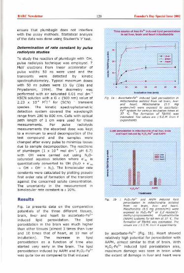
BARC NewdeU" !20 Fouod,,', Day Speda! "me 2002
ensure that plumbagin does not interferewith the assay methods, Statistical analysisof the data was done using Student's 't' test.
Determination of rate constant by pulseradiolysis studies
To study the reaction of plumbagin withOH,pulse radiolysis technique was employed. 7MeV electrons from linear accelerator ofpulse widths 50 ns were used and the
transients were detected by kineticspectrophotometry. Typical maximum doseswith 50 ns pulses were 15 Gy (Das andPriyadarsini, 1994). The dosimetry wasperformed with air saturated 0.01 mol dm"KSCN solution with aGE (500 nm) value of2.23 x 10" M'r' for (SCN) - transientspecies. The kinetic spectrophotometricdetection system covered the wavelengthrange from 280 to 800 nm. Cells with opticalpath length of 1 em were used for thesemeasurements. For pulse radiolysismeasurements the absorbed dose was keptto a minimum to avoid decomposition of thetest compound and the samples werechanged after every pulse to minimize lossesdue to sample decomposition. The reactionsof plumbagin (1 x 10" mol dm", pH 6.7)withOH were carried out using N,O-saturated aqueous solution where e-" isquantitatively converted to 'OH (N,O + e-"-7 'OH + OW + N,). The bimolecular rateconstants were calculated by plotting pseudofirst order rate of formation of the transient
against the concerned solute concentration.The uncertainty in the measurement Inbimolecular rate constant is . 10%.
Results
Fig. 1a presents data on the comparativepotentials of the three different tissues,brain, liver and heart to ascorbate-Fe'"induced lipid peroxidation. The lipidperoxidation in the brain was much higherthan other tissues (almost 3 times than liverand 10 times that of heart, at 10 min ofincubation). The increase in lipidperoxidation as a function of time alsostarted very early in the brain. The lipidperoxidation induced by AAPH and H,O,-Fe'"was quite low as compared to that induced
experimen"
by ascorbate-Fe'. (Fig. 1b). Heart showedrelatively high potential for peroxidation withAAPH, almost similar to that of brain. WithH,O,-Fe'" induced lipid peroxidation also,maximum damage was seen in brain whilethe extent of damage in liver and heart were

BARC N,w",tter 121 Foond,,', Day Sp,da' I"n' 2002
much less and almost similar. Thedifferential susceptibilities of the threetissues can be due to varied composition ofsubstrate for lipid peroxidation as well as therelative amounts of different antioxidants.
Conoan...on effe'" of P'umb..'n In ,,' ""if\;;~hOnOri'on "',.Fe" _nO".. ",10 pen"'O..'on
L~.~': '~
, ---LJ,O~, ,,:=.. ";:"."'~'",~~:.::..
Con"n"'oneffeotofPlum".'n" "tb"lnmltoohonOri,"A".F,".lnOu,odlipIOpero"da'on
, '"iI'"
~ '"~'"
F'g. 2 ,
The effects of plumbagin, added in ethanol,on lipid peroxidation in rat liver and brainmitochondria are shown in Fig. 2. In liver,addition of plumbagin showed aconcentration dependent inhibition of lipid
peroxidation (Fig. 2a). The inhibitionamounted to 79.44 % with 100 "M, 95.27 %with 500 "M and 69.23 % with 2.5 mM. In
brain, the pattern of alteration was different(Fig. 2b). With 100 and 500 "M there were
enhancements of lipid peroxidation by 10.43% and 5.42 % respectively. At a higherconcentration of 2.5 mM, on the other hand,
it showed inhibition of lipid peroxidation(49.26 %).
TimoCou~o of "".F021ind"",0IiPI0 pero,'O,'on in 'of ","'ml""h"O,', In p'"""" 'nO ,h"n" of plumh'g'n
~ L-l--!1~
/[ j ~~ "
i1O.~,+
'",ub,lI" IImolmlnl
TIme,ou"" of Aso.Fe".lnduoad lipid peroxidati" In """"nml""hondria In prose"" and aboenoa of plom..,ln
i~~~'"~~f'
IN IIlml/, no ,%
of a'wbote.Fe"fmm ,at livec
mnochond,la wit,"wpo,a"d ducing i,olatlon. Theon of plumbagin in Ii'"~ia wa, 156 pM and in 138
foemation of TBAR5 wa, "timated." ace of5,EM. f'om 4 expeelm.oI,.
. p< 0.01 a, ;ompaced to ce'peeti" contm/,

BARC N,w,],""
Fig 3 shows the extent of inhibition observedwhen plumbagin was incorporated intomitochondria from the three tissues duringtheir isolation. The inhibition observed in ratliver mitochondria (Fig. 3a) with 156 .oM was
very prominent and amounted to 96.35 % at5 min (P<O.OI), 85.58 % at 30 min(P<O.OI), and 91.97 % (P<O.OI) at 60 min.The inhibition by plumbagin (138 "M) inbrain mitochondria (Fig. 3b) was loweramounting to 56.32 % at 5 min, 64.68 % atIS min, 54.65 % at 30 min and 53.20 % at60 min. In heart mitochondria (Fig. 3c) toothe incorporated plumbagin showed asignificant inhibition (P<O.OOI), amountingto 68.7 % at 60 min of incubation.
The effects of incorporated plumbagin onlipid peroxidation induced by H20,-Fe2. indifferent tissues are shown in Fig 4. In bothliver and brain (Fig 4a and Fig 4b),plumbagin did not show any significant effectover the entire incubation period of 60 min.However, in rat heart mitochondria,plumbagin incorporation showed significantinhibition of lipid peroxidation. Similarinhibition by plumbagin incorporation wasalso seen with AAPH-induced lipid
peroxidation in heart but not in other tissues(Table I). In liver, however, there was nosignificant effect.
122 Found,,', Day Sp,dal ]"u, 2002
F'g. 4
'P<
respective controls
Figs.5 and 6 show the effect of plumbagin onthe levels of two mitochondrial enzymesnamely ATPase and succinate dehydrogenase(SOH). Plumbagin did not influence thelevels of total ATPase altered by bothascorbate-Fe2. and H,O2-Fe'. in rat livermitochondria (Fig Sa & 5b). The effect ofplumbagin on AAPH induced oxidativedamage of SOH is shown in Fig 6a and Fig6b. Since ascorbate interfered with SOH
assay, we could not ascertain the effect ofplumbagin incorporation on ascorbate-Fe'.induced damage to SOH. In both liver andbrain mitochondria, plumbagin was able tosignificantly protect SOH against oxidativedamage.
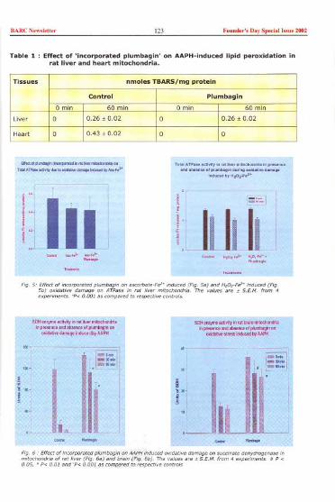
BARC New,'ett" 123 Fouod,,', Day Speda! '..ue 2002
Table 1 : Effect of 'incorporated plumbagin' on AAPH-induced lipid peroxidation inrat liver and heart mitochondria.
--.,-"(""""",',",--""",,,,,T""A"_""~,~"",.,r;w"_m"""by,,,.,,,2'
T.b'AT>~"""""","...m'Io",""",",ro".,,..""".".."".",,.,..,.,.<1,.0..,,....
'"'"""YH,O,~."
1
.
"1
.
'
11.
"'
.
"
1
1. Ir M
! .; I
! ':, j! ~"
,--~-
1.1 1111 E-,.." " ""..'"",".'" .,0,.,," ',0,.,,',
""m",,"~
Fig,at
SDH""Yme""""Y"IrntbrnlllmitochoodriaIlIp""",,"'da""""~~"mba!JIIIOil
",""'"",,,,'oo"""byAA'H
~
g
ti
Tissues nmoles TBARSjmg protein
Control Plumbagin
0 min 60 min 0 min 60 min
Liver 0 0.26 t 0.02 0 0.26 I 0.02
Heart 0 0.43 I 0.02 0 0
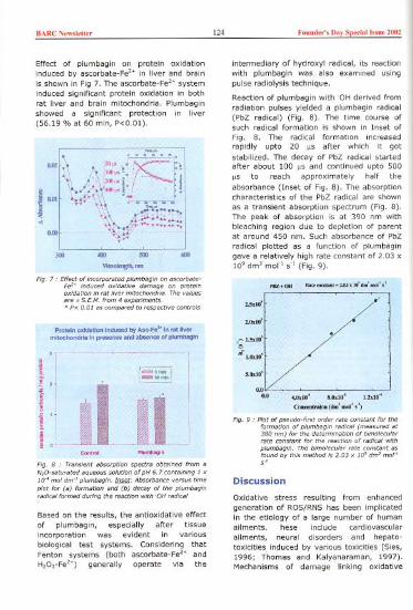
BARC N<w,Io"" 124 Found,,', Do> Spedal Issoe 2002
Effect of plumbagin on protein oxidationinduced by ascorbate-Fe" in liver and brainis shown in Fig 7. The ascorbate-Fe'" systeminduced significant protein oxidation in bothrat liver and brain mitochondria. Plumbaginshowed a significant protection in liver(56.19 % at 60 min, P<O.Ol).
'""",_.j"-:'l002f., .
~I](""'~,i'< '
I
"\\ 1>'.
1""
.
'"1-1.1
,...,
':<.
\~.J£.\ 400",<'" '. - - .
!~~~ooo>~-300 400 500
_run600
Fig. 7. Effeot of inca.po.ored plumbagin on ",co.bate-Fe" induced oxidative damage on pmteinoxidation in cat live. mitochondcia. The valu",ace" SEM. f.om 4 expcoiments."P< 0.01 as rompa.ed to .",peoti" contmls
Protein oxidation induoed by A,..F'~ in <at lI..rmitochondria In prosenoe and a...noe of plumbagin
i~
II~!ij
~Fig. 8 . Tcansient abso.ption speetca obtained fmm aN,O-satu.ated aqueous solution of pH 6.7 rontaining 1 x10~ mol dm' plumbagin. IDm; Abso.bance vcosus time
plot fa. (a) fo.mation and (b) decay of the plumbagin
(adical fo.med ducing the "action withOH cadical
Based on the results, the antioxidative effectof plumbagin, especially after tissueincorporation was evident in variousbiological test systems. Considering thatFenton systems (both ascorbate-Fe'" andH,O,-Fe'") generally operate via the
intermediary of hydroxyl radical, its reactionwith plumbagin was also examined usingpulse radiolysis technique.
Reaction of plumbagin with 'OH derived fromradiation pulses yielded a plumbagin radical(PbZ radical) (Fig. 8). The time course ofsuch radical formation is shown in Inset ofFig. 8. The radical formation increasedrapidly upto 20 "s after which it gotstabilized. The decay of PbZ radical startedafter about 100 "s and continued upto 500"s to reach approximately half theabsorbance (Inset of Fig. 8). The absorptioncharacteristics of the PbZ radical are shownas a transient absorption spectrum (Fig. 8).The peak of absorption is at 390 nm withbleaching region due to depletion of parentat around 450 nm. Such absorbance of PbZradical plotted as a function of plumbagingave a relatively high rate constant of 2.03 x10' dm' mol-' so, (Fig. 9).
", '-2.03."I"",'m"",'
2."'10'
2.1"10'
_~I.'do':.-"'-U!dO'
'-OdO'
0.00.0 4.0dO~ 8.OdO~ 1.2dO<
Coo " (Om' -' ,-')
Fig. g . Plot of pseudo-fiost "dco cate roes"nt fa. thefo.mation of plumbagin cadical (measu"d at380 nm) fa. the detcomination of bimolecula<cate constant fa. the "action of cadical withplumbagin. The bimolecula< cate constant asfound by this method is 2.03 x 10' dm' mot's'
Discussion
Oxidative stress resulting from enhancedgeneration of ROS/RNS has been implicatedin the etiology of a large number of humanailments. hese include cardiovascularailments, neural disorders and hepato-toxicities induced by various toxicities (Sies,1996; Thomas and Kalyanaraman, 1997).Mechanisms of damage linking oxidative

BARC New,"tter 125 Founder', Day Speciall"ue 2002
stress to disease involve undesirablealterations to lipid and protein componentsof membranous organelles (Sies, 1996;Cuzzocera, Riley et aI., 2001). Among thesubcellular organelles, mitochondria areconsidered as important (major) targets ofoxidative damage being responsible forreduced cellular functions in the form ofenergy generation or responsible for celldeath (Raha and Robinson, 2000). Oxidativedamage to mitochondria adversely affectsspecific carriers for succinate, citrate andoxaloacetate, as a result their intracellularlevels are reduced (Salet and Moreno, 1990).Membrane lipids, due to the presence ofpolyunsaturated fatty acids, are highly proneto oxidative damage induced by variousoxidants. In our studies we have usedmitochondria from rat liver, brain and heartwhose damage may be linked to the diseasesfor which Plumbago zeylanica has beensuggested as a cure.
P. zeylanica has been credited with varioustherapeutic properties. Some of thesepertain to diseases of the nervous,cardiovascular and gastrointestinal systemsas well as for hepatotoxicities. Plumbaginfrom P. zeylanica has been suggested as the'active ingredient' in medications and herbalpreparations (Gupta, Verma et aI., 1993). Toexamine possible mechanisms of action, wehave studied the ability of plumbagin toprevent oxidative damage in mitochondriaisolated from these tissues. The threeendogenously relevant systems areascorbate-Fe'. that generates 'OH radical-like species, H,O,- Fe'. that yields 'OH andAAPHthat releases peroxyl radical (ROO') onincubation at the physiological temperatureof 37 °C (Kamat, Boloor et aI., 2000). Theabove three systems also differ In theirmechanisms in inducing lipid peroxidation.
The responses of the tissues used namelybrain, liver and heart to the abovementioned oxidant-generating systemssignificantly differ. Brain is rich inpolyunsaturated fatty acids that aresubstrates for peroxidation. Liver and heartcontain lesser amounts of these components.The amounts of endogenous antioxidants likeglutathione, vitamins C and E as well as
antioxidant enzymes also are different inthese tissues (Pushpendran, Subramanian etai, 1998). The differential response of thethree tissues to oxidants as well as theextent of inhibitions with plumbagin can beattributed to these factors.
Lipid peroxidation in tissues is controlled bythe interaction of several factors. Theseinclude (i) availability of substrates forperoxidation in the form of unsaturated fattyacids mainly present in phospholipids, (ii)inducers of peroxidation such as ascorbate,Fe'., compounds which can convert Fe'. toFe'., oxygen, initiators of free radicalreactions and functioning of the electrontransport chain which serve as sources ofreactive species, (iii) antioxidant defense inthe form of glutathione, a-tocopherol,superoxide dismutase, carotenoids,substances chelating Fe'., substancesreducing lipid hydroperoxide, a GSHdependent iabile factor and glutathioneperoxidase system etc., and (iv) the physicalproperties of the membrane lipid such asfluidity and surface charge and the locationof the polyunsaturated fatty acid in themembrane. Our earlier studies showed thatthe tissues examined (brain, liver and heart)significantly differ from each other in theirsusceptibility to undergo lipid peroxidationwhen oxidative damage is induced in vitro(Devasagayam, 1983; Pushpendran,Subramanian et al., 1998). Among thesetissues brain is extremely susceptible tooxidative damage due to high levels ofunsaturated fatty acids and the increasedcapacity of oxygen consumption (Kamat andDevasagayam, 1999).
Plumbagin protects against oxidativedamage in majority of our experiments. Theinhibition is observed with lipid peroxidation,protein oxidation as well as againstInactivation of succinate dehydrogenase. Theprotective effect, however, was not seenwith ATPase. Among the three systems usedto Induce oxidative damage, protection wasobserved against oxidative damage inducedby ascorbate-Fe'. and AAPH,and not againstH,O,- Fe'.. This can probably be attributedto inability of plumbagin to neutralise eitherH,O, or Fe'. or both in this system.

BARC Now,lettor 126 Fouod,,', Day Spocial b'ue 2002
Incorporation of plumbagin into mitochondriaalso was more effective than externaladdition to mitochondria. This may possiblybe due to better uptake and presence ofplumbagin at the site of ROS generationinside mitochondria. The extent of inhibitionobserved is relatively less as compared toother antioxidants like a-tocopherol,tocotreinols or curcumin (Nesaretnam,Devasagayam et aI., 1993; Kamat andDevasagayam, 1995; Sreejayan, Rao et aI.,1997; Devasagayam, Kamat et al., 2001).Hence it may indicate that P. zeylanlca mayalso contain other components with betterantioxidant activities.
Though in our experiments plumbagin hasnot been used in whole cell systems, wholeorgans or animal levels many studies usingsuch systems have indicated the beneficialeffects of plumbagin. For instance it hasimmunomodulatory effects as assessed bymacrophage functions in BALB/c mice(Kamal and Rao, 1995), and anticancereffects in different systems such as Ehrlichascites tumors and sarcoma 180 in mice(Singh and Udupa, 1997; Naresh, Udupa etaI., 1996, Devi, Solomon et aI., 1999),lymphocytic leukemia in mice(Krishnaswamy and Punushothaman, 1980),Dalton's ascites lymphoma in mice(Kavimani, Jlango et aI., 1996),methylcholanthrene induced fibrosarcoma inrats (Krishnaswamy and Punushothaman,1980) and azoxymethane induced intestinalcarcinogenesis in rats (Sugie, Okamoto et al.1998). Similar in vivo studies for checkingthe antioxidant activity of plumbagin usingvarious indicators of oxidative damage canyield rich dividends.
In certain systems plumbagin has beenobserved to have prooxidant effects due toits redox cycling. This is observed mainly inbiological systems lacking superoxidedismutase (SOD) as in the case of anaerobicbacteria. This also has been postulated toaccount for its antimicrobial activity(Archibald and Fridovich, 1981; Diguiseppiand Fridovich, 1982). In aerobic systems,however, such an effect was not observed.
The possible reason for the observed
antioxidant effect of plumbagin can be due 1to radical scavenging as observed by pulseradiolysis. In our studies we have shown that Ireaction of radiation derived radicals lead tothe formation of plumbagin radical that isfairly stable. The radical is probably aphenoxyl type of radical. The characteristicabsorption peak at 430 nm is buried into the
I
bleaching spectrum due to the depletion ofthe parent. But the broad absorption around500 nm due to the said radical is evident.The decay of the radical as measured at 390nm was found to be of mixed order. Thespectral as well as kinetic characteristics ofthe radical, matches well with the knownphenoxyl radical. Hence the mechanisticpathway for the free radical scavengingproperty of plumbagin is via the formation ofphenoxyl radical.
In conclusion, our studies show thatplumbagin, isolated from P. zeylanlca exhibitantioxidant effects in the form of membraneprotective properties in mitochondria fromthree different rat tissues, liver, brain andheart. The extent of inhibition observeddiffers in these tissues. The observedantioxidant effects of plumbagin can beexpiained based on its ability to scavengeOH, as is seen in our pulse radiotysisexperiments. The antioxidant ability ofplumbagin, considered as the activeingredient of P. zeylanlca, may at ieast, inpart, explain observed therapeutic propertiesof this medicinal plant.
Acknowledgements
The authors wish to thank Dr K.B. Sainis,Head, Cell Biology Division, for hisencouragement and heipful suggestions aswell as Mr D.V. Katho!e for his excellenttechnical assistance. They also wish to thankDr Gnanadhass Devasahayam, Professor,Government Siddha Medical College,Tirunelveli, Tamil Nadu, for his helpfulsuggestions regarding P. zeylonlca andemphasizing the importance of this medicinalplant in Indian systems of medicine, whichprompted the authors to take up this work.
BARCN'w",tt" 127 Fouud,,', Day Sp,dall,"u, ZOOZ
References
1. Archibald, F.S. and Fridovich, I. (1981).Manganese, superoxide dismutase, andoxygen tolerance in some lactic acidbacteria. J. Bacteriol. 146: 928-936.
2. Bhargava, S.K. (1986). Effect oftestosterone replacement therapy onquantitative spermatogenesis followingplumbagin treatment in immature rats.Acta. Eur. Fertil. 17: 217-219.
3. Caplan, A.!. and Greenawalt, J.W.(1968). The effect of osmotic lysis onthe oxidative phosphorylation andcompartmentation of rat livermitochondria. J. Cell BioI. 36: 15-31.
4. Cuzzocrea, S., Riley, D.P., Caputi, A.P.and Salvemini, D. (2001). Antioxidanttherapy: a new pharmacologicalapproach in shock, inflammation, andischemia/reperfusion injury. Pharmacol.Rev. 53: 135-159.
5. Devasagayam, T.P.A., Pushpendran,c.K. and Eapen, J. (1983). Differences inlipid peroxidation in rat liver rough andsmooth microsomes. Biochim. Biophys.Acta. 750: 91-97.
6. Devasagayam, T.P.A. (1986). Lipidperoxidation in rat uterus. Biochim.Biophys. Acta. 876: 507-514.
7. Devasagayam, T.P.A., Kamat, J.P. andSreejayan N. (2001). Antioxidant actionof curcumin. In: Microneutrients andHealth. : Molecular Biology Mechanism.Edited by Nesaretnam K. and Packer L..AOCS Press, Champaign, IL, USA,pp.42-59.
8. Devi, U., Solomon, F.E. and Sharada,A.C (1999). Plumbagin, A plantnaphthoquinone with antitumor andradiomodifying properties. Pharma-ceutic. BioI. 37: 231-236.
9. Diguiseppi, J. and Fridovich, I. (1982).Oxygen toxicity in Streptococcussanguis. The relative importance ofsuperoxide and hydroxyl radicals. J. BioI.Chem. 257: 4046-4051.
10. Dinda, B. and Saha, S. (1989). A newbinaphthoquinone from Plumbagozeylanica Linn. Indian J. Chem. SectionB- Org. Chem. Including Med. Chem. 28:984-986.
11. Dinda, B., Hajra, A.K. and Chel, G.(1997). Naphthoquinones of Plumbagospecies - A Review. J. Indian Chem.Soc. 74: 974-979.
12. Durga, R., Sridhar, P. and Polasa, H.(1992). Antimutagenic activity ofplumbagin in Ames Salmonellatyphimurium test. Indian J. Med. Res.96: 143-145.
13. Gunaherath, G.M.K.B., Gunatilaka,A.A.L. and Thomson, R.H. (1988).Studies on medicinal and related plantsof Sri Lanka: Part 18. Structure of a new
naphthoquinone from Plumbagozeylanica. J. Chem. Soc. Perkin Transac.10: 407-410.
14. Gupta, M.M., Verma, R.K., Uniyal, G.c.and Jain, S.P. (1993). Determination ofplumbagin by normal phase highperformance liquid chromatography. J.Chromat. 637: 209-212.
15. Gupta, A., Siddiqui, I.R., Singh, J.,2000. A new anthraquinone glycosidefrom the roots of Plumbago zeylanica.Indian J. Chem. 39 B, 796-798.
16. Hammer, c.T., Wills, E.D., 1978. Therole of lipid components of the diet inthe regulation of fatty acid compositionof the rat liver endoplasmic reticulumand lipid peroxidation. Biochem. J. 174,385-393.
17. Itoigawa, M., Takeya, K., Furukawa, H.,1991. Cardiotonic action of plumbaginon guinea-pig papillary muscle. PlantaMed. 57, 317-319.
18. Kamat, J.P., Devasagayam, T.P.A.,1995. Tocotrienol from palm oil aspotent inhibitors of lipid peroxidationand protein oxidation in rat brainmitochondria. Neurosc!. Lett. 195, 179-182.
19. Kamat, J.P., Devasagayam, T.P.A.,1996. Methylene blue plus light inducedlipid peroxidation in rat livermicrosomes: inhibition by nicotinamide(vitamin B3) and other antioxidants.Chem.-Biol. [nteract. 99, 1-16.
20. Kamat, J.P., Devasagayam, T.P.A.,1999. Nicotinamide (vitamin B3) as aneffective antioxidant against oxidativedamage in rat brain mitochondria. RedoxReport. 4, 179-184

BARC N,w,'et'er 128 Founder', Day Sp,da' '"n, 2002
21. Kamat, J.P., Boloer, K.K" Devasagayam,T,P,A" 2000. Chlorophyllin as aneffective antioxidant against membranedamage in vitro and ex vivo. Biochim,
Biophys, Acta. 1487, 113-127.22. Kirtikar, K.R., Basu, B.D., (Eds) 1984,
Indian Medicinal Plants, Vol - I & II,Publishers Blatter, E., Cauis, J.R. andMhaskar, K.5" Basu, L.M" Allahabad,India.
23, Lele, R.D., 1999, Ayurveda (ancientIndian system of medicine) and modernmolecular medicine. J. Assoc, Physicians,India, 47, 625-628.
24. Lele, R.D., 2001. Ayurveda and modernmedicine. Bharatiya Vidya Bhavan,Mumbai.
25, Mantle, D" Lennard, TW" Pickering,A.T" 2000, Therapeutic applications ofmedicinal plants in the treatment ofbreast cancer: a review of their
pharmacology, efficacy and tolerability.Adverse Drug React. Toxicol. Rev. 19,223-240.
26. McDermott, J.H., 2000. Antioxidant
nutrients: current dietaryrecommendations and research update,J. Am. Pharm. Assoc. 40, 785-799.
27. Munday, A.D" Sriratana, A., Hill, J.5"Kahl, S.B., Nagley, P" 1996.Mitochondria are the functional
intracellular target for a photosensitizingboronated porphyrin. Biochim, Biophys,Acta. 1311, 1-4.
28. Nesaretnam, K., Devasagayam, T.P,A"Singh, B.B" Basiron, Y" 1993. Influenceof palm oil or its tocotrienol-rich fraction
on the lipid peroxidation potential of ratliver mitochondria and microsomes.
Biochem. Mol. BioI. Intematl. 30, 159-167,
29, Okamoto, T., Hino, 0., 2000. Drugdevelopment with hints from traditional
Indian Ayurveda medicine: hepatitis andrheumatoid as an example, Int. J. Mol.Med, 6, 613-615,
30, Oyedapo, 0,0" 1996. Studies on
bioactivity of the root extract ofPlumbago zeylanica. Int, J. Pharm. 34,365-369,
31. Palamanda, J,R, and Kehrer, J.P., 1992,Inhibition of protein carbonyl formation
and lipid peroxidation by glutathione inrat liver microsomes, Arch, Biochem,
Biophys. 293: 103-109.32. Payne, c.M., Bernstein, c., Bernstein,
H., Gerner, E.W., Garewal, H., 1999.Reactive nitrogen species in colon
carcinogenesis, Antioxid. Redox Signal.1,449-467,
33, Premakumari, p" 'Rathinam, K"
Santhakumari, G., 1977. Antifertilityactivity of plumbagin, Indian J, Med,Res. 65, 829-838.
34, Pushpendran, c.K., Subramanian, M.,
Devasagayam, T,P,A., Singh, B.B.,1998, Study on lipid peroxidationpotential in different tissues induced byascorbate-Fe": Possible factors involved
in their differential susceptibility. Mol.Cell. Biochem. 178, 197-202.
35. Quigley, J.P. and Gottere, G.5., 1969,Distribution of (Na' -K')-stimulatedATPase activity in rat intestinal mucosa.Biochim, Biophys. Acta. 173,456-468,
36, Raha, 5" Robinson, B.H., 2000,
Mitochondria, oxygen free radicals,disease and ageing, Trend. Biotechnol.25, 502-508,
37. Rao, A,V" Agarwal,S., 2000. Role ofantioxidant Iycopene in cancer and heartdisease. J, Am, Coil. Nutr. 19, 563-569,
38. Sajan, M.P., Satav, J.G., Bhattacharya,R,K, 1995. Activity of some respiratory
enzymes and cytochrome contents in rathepatic mitochondria following aflatoxinB, administration. Toxicol. Lett. 80, 55-60.
39, Salet, c., Moreno, G" 1990. New trendsin pathobiology, Photosensitisation ofmitochondria. Molecular and cellular
aspects. J. Photochem. Photobiol. B BioI.5, 133-150.
40, Sharma, A., Singh, R,T., Sehgal, V"Handa, 5.5., 1991a. Antihepatotoxicactivity of some plants used in herbalformulations. Fitoterapia. 62, 131-138.
41. Sharma, I., Gusain, D., Devi,P,U"1991b, Hypolipidaemic andantiatherosclerotic effects of plumbaginin rabbits. Indian J. Physiol. Pharmacol.35, 10-14,

BARC N'w,I,"" 129 Found,,', Day Sp,dall..ne 2002
42. Sies, H., 1996. Antioxidants in Disease,Mechanisms and Therapy. AcademicPress, NewYork.
43. Sreejayan N., Rao, M.N.A., Priyadarsini,K.I., Devasagayam, T.P.A., 1997.Inhibition of radiation induced lipidperoxidation by curcumin. Int. J. Pharm.151, 127-130.
44. Sugie, 5., Okamoto, K., Rahman, K.M.,Tanaka, T., Kawai, K., Yamahara, J.,Mori, H., 1998. Inhibitory effect ofplumbagin and juglone onazoxymethane-induced intestinal
carcinogenesis in rats. Cancer lett. 127,177-183.
45. Thakur, R.5., Puri, H.S. and Husain, A.,1989. Major Medicinal Plants of India.,Central Institute of Medicinal andAromatic Plants, Lucknow, India.
46. Thomas, CE., Kalyanaraman, 8., 1997.Oxygen Radicals and the DiseaseProcess. Harwood Academic Publishers,The Netherlands.
47. Tripathi, Y.B., 2000. Molecular approachto ayurveda. Indian J. Exp. BioI. 38,409-414.
This p{lper won Ihe Besl Posler {lw{lrd {II Ihe lnlern{llion{ll Conference on "N{llur{l1Anlioxitl{lnts m,d Free R{ldic{lls in Hum{ln He{llth & R{ldi{ltion Biology (NFHR-
2(11l/}" held {IIMumh{li during July 2/-24, 20111.
About the authors ...
Ms Meenaf Banerjee ,eceived hecM.Sc. degcee in Microbiology fromSchool of Life Sciences, Devi AhilyaVishva Vidyalaya, Indoce, m 2001.Recentiy she he> joined NeeS, Pune,forhecPhD. Deg,'e.
iJ

BARCN,w,',"" 130 Found,,', Doy Sp,"o' I,,", 2002
Molecular Evidence that the IndianPopulation of Colletotrichum graminicola(sorghum anthracnose) is Hypervariable
J. Latha, Apratim Chakrabarti, Prasun K, Mukherjee and R.P. ThakurO,,"ioc
Abstract
Introduction
Sorghum anthracnose, caused byColletotrichum graminicola (Ces.) Wilson, isa destructive disease responsible for as highas 50% loss in grain yield (Ali and Warren,1992). Colletotrichum graminicola is a highlyvariable pathogen. It is well recognized thatpathogenic variability poses difficulty indevelopment and deployment of effectivehost resistance, which is a dependable andeconomic means of disease management. In
India, several sorghum hybrids with multipledisease resistance are cultivated
commercially. A rapid and reproducible toolfor characterizing the pathogen genotypes
would help researchers to follow the shift ingenetic make-up of the pathogen populationand thus providing a dynamic picture of theinteractions between the host and pathogen
genotypes. This would, in turn, help devisingstrategies for management of this disease.Genetic variability in this fungus is widelystudied by using molecular tools like RFLPand RAPD. Restriction analysis of the
intergenic spacer region of the rDNA repeatshas been useful for variability studies insome fungi like Fusarium oxysporum (Appeland Gordon, 1995; Chakrabarti et al. 2001)and Pyrenophora graminea (Pecchia et aI.,
1998). Once optimized (primer sequencesand enzyme combinations), this techniquecombines the advantage of both PCR(simplicity and speed) and RFLP(reproducibility).
Materials and Methods
The C. graminicola isolates were collectedfrom six provinces of India where sorghum iscultivated widely. Monoconidial isolates weregrown in potato dextrose medium and DNAisolated according to Mukherjee (1999). ForRAPDanalysis, six random primers from kitA of Operon Technologies, Inc. (OPA- 1, 2, 5,9, 10 and 15) were used. These primerswere selected after a primary screening of allthe 20 primers from kit A. For amplification,SOng of DNA, 0.2mM primer, O.lmM eachdNTPs and 1.0U Taq polymerase (Genei)
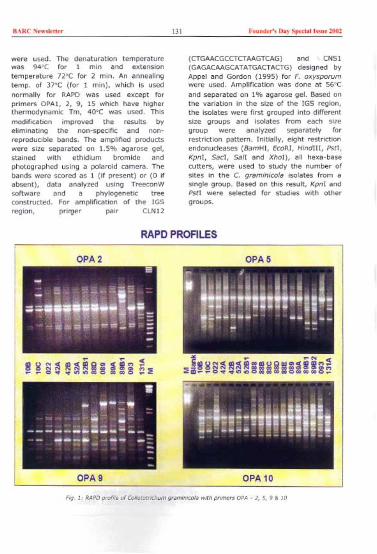
BARC New,'etter 131 Founder', Day Spedellssue ~O2
were used. The denaturation temperaturewas 94"C for 1 min and extensiontemperature 72'C for 2 min. An annealin9temp. of 37'C (for 1 min), which is usednormally for RAPD was used except forprimers OPAl, 2, 9, 15 which have higherthermodynamic Tm, 40'C was used. Thismodification improved the results byeliminating the non-specific and non-reproducible bands. The amplified productswere size separated on 1.5% agarose gel,stained with ethidium bromide andphotographed using a polaroid camera. Thebands were scored as 1 (if present) or (0 ifabsent), data analyzed using TreeconWsoftware and a phylogenetic treeconstructed. For amplification of the IGSregion, prirger pair CLN12
(CTGAACGCCTCTAAGTCAG)and, CNSI(GAGACAAGCATATGACTACTG)designed byAppel and Gordon (1995) for F. oxysporumwere used. Amplification was done at 56'Cand separated on 1% agarose gel. Based onthe variation in the size of the IGS region,the isolates were first grouped into differentsize groups and isolates from each sizegroup were analyzed separately forrestriction pattern. Initially, eight restrictionendonucleases (BamHI, EcoR!, HinclIII, Pstl,Kpn!, Sad, Sail and Xho!), all hexa-basecutters, were used to study the number ofsites in the C. gram;n;co!a isolates from asingle group. Based on this result, Kpnl andPst! were selected for studies with othergroups.
OPA2
RAPDPROFILES
OPA5
OPA9
Fig. 1, RAPD pcofile ofCo/fetotrlchum gramlnleola with w'me" DPA - 2,5,9 & 10
CPA 10

BARC N,w,I,U"
Fig. 2 i
Results and discussion
Of the eighteen isolates from differentlocalities/single lesions, the isolates 88, 888,
8SC, 8SD & S8E (all from a single lesion)were exactly the same with respect to the
RAPD profile with the six primers tested. Thesame was true for 8981 and 8982; though8981/82 differed considerably from 89 and89A (all derived from sin91e lesion). All theisolates (except the two groups mentioned
Found,,', D"y Spedal bm 2002
M
10B
10C
42A
42B
52B1
131A
22
88B
89
89B1
93
29
141
160
195
35
123
124
48
158
above) were different from each other, eventhough some originated from the samelesion (Fig. 1). 8y and large, two majorclusters were formed: 8981/8982 as one &the rest as one. There was no effect of placeof isolation, rather two isolates from twodifferent provinces (eg. 42A from Andhrapradesh and 52A from Maharashtra) werecloser to each other than two isolatesoriginating from even the same lesion (e.g.:42A and 428). RAPD analysis of C
132
M
10B
10C
42A
42B
52B1
131A
22
88B
89
89B1
93
29
141
160
195
35
123
124
48
the
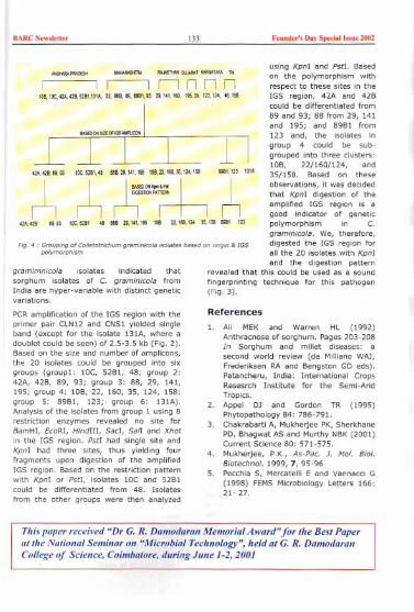
BARCNew,lctter Fonnder', Day Spedall"ne 2002133
using Kpnl and Pstl. Basedon the polymorphism withrespect to these sites in theIGS region, 42A and 42Bcould be differentiated from89 and 93; 88 from 29, 141and 195; and 89B1 from123 and, the isolates ingroup 4 could be sub-grouped into three clusters:lOB, 22/160/124, and35/158. Based on theseobservations, it was decidedthat KpnI digestion of theamplified IGS region is agood indicator of geneticpolymorphism in C.graminieota. We, therefore,digested the IGS region forall the 20 isolates with KpnIand the digestion pattern
revealed that this could be used as a soundfingerprinting technique for this pathogen(Fig. 3).
"""""" GWAAAT"""T"" TN""""""""""""""""
I Ir-Innnn108.1oo.42A.428.5281.131A,2"'86.89.8961.93.29.141.160. 195.35.123.124.48.158
42A.42889." 1OC.5281.48 88S,29.141.195 1OS.".160.~.I24.158 8981.123 13"
I I I ~,"~I~~ I I
n n r-;~OON"rlin42A"" ".93 100.5281 48 888 29.141.195108 22.1ao.l2435.1588981 123
FIg. 4 , GroupIng of eollctotrichum g,.mlnlcola ',olates b..cd on orIgIn & IGSpolymorphism
gramimnicota isolates indicated thatsorghum isolates of C. graminieota fromIndia are hyper-variable with distinct geneticvariations.
PCRamplification of the IGS region with theprimer pair CLN12 and CNS1 yielded singleband (except for the isolate 131A, where adoublet could be seen) of 2.5-3.5 kb (Fig. 2).Based on the size and number of amplicons,the 20 isolates could be grouped into sixgroups (group1: laC, 52B1, 48; group 2:42A, 42B, 89, 93; group 3: 88, 29, 141,195; group 4: lOB, 22, 160, 35, 124, 158;group 5: 89B1, 123;. group 6: 131A).Analysis of the isolates from group 1 using 8restriction enzymes revealed no site forBamHI, EcoRI, HindIII, SacI, Sail and XhoIin the IGS region. PstI had single site andKpnI had three sites, thus yielding fourfragments upon digestion of the ampiifiedIGS region. Based on the restriction patternwith KpnI or PstI, isolates laC and 52B1could be differentiated from 48. Isolatesfrom the other groups were then analyzed
References
1. Ali MEK and Warren HL (1992)Anthracnose of sorghum. Pages 203-208In Sorghum and millet diseases: asecond world review (de Mililano WAJ,Frederiksen RA and Bengston GD eds).PatancheN, India: International CropsResesrch Institute for the Semi-AridTropics.
2. Appel DJ and Gordon TR (1995)Phytopathology 84: 786-791.
3. Chakrabarti A, Mukherjee PK,SherkhanePD, Bhagwat AS and Murthy NBK(2001)Current Science 80: 571-575.
4. Mukherjee, P.K., As-Pac. J. Mol. Bioi.Biotechnol. 1999, 7, 95-96
5. Pecchia S, Mercatelli E and Vannaccl G(1998) FEMS Microbiology Letters 166:21- 27.
This paper received "Dr G. R. Damodaran Memorial Award" for Ihe Besl Paperallhe Nalional Seminar on "Microbial Technology", held al G. R. DamodaranCollege of Science, Coimbalore, during June 1-2, 2001

BARCNew,""" 134 Foond,,', Day Special Issoe 2002
About the authors ...
the 42"' batch Schoo/
41" batchHe woeked in the
BARC Now,k"" 135 Foood,,', D,y Sp""" "'"0 2002
RadionuclideBiomass
Biosorption by Bacterial
Pinaki Sac and S. F. D'SouzaD"i""
Abstract
Introduction
Radionuclide and heavy metal pollution byvarious industrial activities is of significantenvironmental concern (Barkay andSchaefer, 2001; D'Souza, 1999a; D'Souza etal 2001a; D'Souza, 2002a), Microbialbioremediation of such toxic compounds areincreasingly being considered as a potentialalternative with high capacity and efficientmetal removal from diluted effluent with
almost no secondary waste generation,(Taxier et ai, 1999 and Lloyd and Macaskie2000), Although considerable studies aremade on microbial removal of heavy metals,radionuclides in this regard remained little
explored. Among the several microbialprocesses that determine the environmentalfate of metallic toxicants viz, reductive or
enzymatic precipitation, solubilization, etc.,biosorptive accumulation of heavy metalsand radionuclides is of recent interest (Gadd2000, Hu et al. 1996, Dhami et a/1998, Sar
et al 1999, Sar and D'Souza 2001 a, b).Bioremediation of radionuclides, heavymetals and organic waste has been a majorrecent activity in the authours laboratory(D'Souza, 1999a; Bhainsa and D'Souza1999; Joshi and D'Souza, 1999; Sar andD'Souza 2001a,b ; Bhainsa and D'Souza,2001a,b; Sar et ai, 2001a,b; Sangurdekar eta/2001, Melo and D'Souza, 2001; D'Souza,et ai, 2001a,b; Kazy, et ai, 2001;Shanmugam et ai, 2001; Sar and D'Souza2002; Kazy et al 2002; Panchapakesan etal,2002; Irani et ai, 2002). Compared to theconventional treatment methods, these
biomass based systems are more acceptablein being cost effective, with high efficiency of
detoxification of even very dilute effluentsand minimizing the disposable sludgevolume. It also offers the flexibility fordeveloping non-destructive desorptiontechniques for biomass regeneration and/orquantitative metal recovery.
BARCNew,""" 136 Found,,', Day Special '"ne 2002
Metal accumulation by microorganisms iseither of energy driven active bioaccu-mulation or metabolism Independent passivebiosorption. The latter process of microbialmetal removal by purely physico- chemicalprocesses seems more appropriate forbioremediation with cation sequestrationmainly regulated by the characteristics of themicroorganism, the targeted metal and thesolution microenvironment. Since, it is thechemical composition of the cell wall andother surface materials responsible for cationsequestration, cell viability or othermetabolic activities that do not interfere withsuch characteristics effectively have noimpact on biosorption. In some cases,pregrowth conditions, particularly, thegrowth medium ingredients also showsignificant influence on biosorptive metaluptake.
Although,' biosorptive uptake of severalheavy metals is well documented, suchstudies on radionuclide sorption arerelatively less. Particularly, with respect touranium, a variety of living and non-livingbiosorbents composed of fungi and bacteriahave been reported to bind the cationconsiderably, whereas reports on thoriumsorption are not impressive. Previous studieson microbial metal sorption by our grouphave identified the strains of Pseudomonasas a potent accumulator of metals andradionuclides (Sar et allgg8, Sar et a/1999,Kazy et al. 1999, Sar et al. 2001a, Sar andD'Souza 2001a, Sar and D'Souza 2002, Kazyet al 2002). The present study wasundertaken to evaluate the uranium (VI) andthorium (IV) biosorptlon capacity of aPseudomonas soil isolate. Equilibriumsorption behavior of the lyophilized biomasswas characterized employing the Freundlichand Langmuir adsorption isotherm models.The effect of solution pH on the chemistry ofbinding sites of both biosorbent types andalso the metallic species in solution wasassessed. Effect of bacterial culture age andpresence of energy sources or metabolicinhibitor on uranium uptake was alsostudied. In view of a multimetalliccomposition of realistic waste, U and Th
sorption in presence of other interferingcations and anions was investigated.
Materials and Methods
Microorganism, growth medium andculture conditions
Pseudomonas sp., a garden isolate wasgrown and maintained in Tris-minimalmedium (Kazy et a/.. 1999). Midexponentialphase cells were collected by centrifugation(12000 x g, 30 mini, washed thoroughlywith distilled water, dried and used forbiosorption experiments.
Uranium andexperiments
All biosorption experiments were done usingdry Pseudomonas biomass. Nitrate salts ofUranium and Thorium was used (UO,(NO,)"6 H,O or Th (NO,)" 5 H,O, Merck,Germany). Other experimental details weresame as described previously (Sar andD'Souza 2001, Sar and D'Souza 2002).Dissolved uranium and thorium wasdetermined either by the Arsenazo IIImethod or by inductively coupled plasmaatomic spectrometry (ICP-AES).
thorium biosorption
The biosorption equilibrium uptake (q, mgmetal g" biomass dry wt.) for each samplewas calculated according to the massbalance on metal ion expressed as :
q ~ V(Co- C,) / M (1)
Where V is the sample volume (I), Co, theinitial metal ion concentration (mg I"), Ceothe equilibrium or final metal concentration(mg r') and M, the biomass dry weight (g).Adsorption isotherm data were also fitted tothe classical Freundlich and Langmuirisotherm equations (De Rome and Gadd1987).The linearized form of isotherm equationsused are:
Freundlich Equation: Logq ~ Log k + l/nLog C, (2)
Where q is the equilibrium metal uptakecapacity and Ceo the residual metalconcentration at equilibrium. The constant 'k'

HARCNo",'o"" 137 Foond,,', Day Spoda' "'"0 2002
is a measure of adsorption capacity and'l/n', the intensity of adsorption.
LangmuirEquation, l/q ~ l/qm" bx l/Ce +l/qm" (3)
The constant 'qm,/ represents the maximumspecific metal uptake and 'b' the ratio of theadsorption/desorption rates related toenergy of adsorption through Arrheniusequation.
Time course of metal biosorption
For sorption kinetic studies, bacterialbiomass (0.5 mg ml") was mixed withuranium or thorium solution (100 mg 1"),samples withdrawn at timed intervals werecentrifuged and dissolved U/Th wasestimated.
Effect of pH on biosorption
The effect of solution pH on U and Thsorption was studied by adjusting the initialpH of the contact solution (100 mg Th 1")over the range pH 2.0-8.0. For pHadjustment, 1.0 M NaOH or 1.0 M HNO, wasused.
Interference of cations and anions on
uranium and thorium biosorption
Uranium and thorium sorption Insimultaneous presence of other interferingions was tested in bimetallic combinations,by adding equimolar concentrations ofuranium or thorium (430 ~M Th or 420 ~MU; equivalent to 100 mg U or Th 1") and testcation or anion. Details are same asdescribed earlier (Sar and D'Souza 2001a,Sar and D'Souza 2002)
Results and Discussion
Selection of uranium accumulatingstrain
Initial study on selecting a good uraniumaccumulating strain was done using four soilisolates, three belonging to Pseudomonas spand one to Bacillus coagulans. All thesebacterial strains were selected based on their
superior metal tolerance capacity. APseudomonas sp. 2 which showed optimal
biosorption was selected for further study onbiosorption of uranium (VI) and thorium(IV).
Effect of growth medium, culture age,energy source and metabolic inhibitor onuranium biosorption
Metal and radionuclide biosorption bymicrobes is strongly influenced by thenature, availability and arrangements ofvarious cellular binding ligands sequesteringcationic metallic species. Among the othersfactors, growth medium ingredients are oftenfound to regulate the synthesis of thesemetal binding moieties. In the present studyPseudomonas cells were pre-grown insynthetic minimal- and peptone containingenriched- medium and their U sorption wascompared. At low uranium concentration(100 mg I-'), comparable metal sorption wasobserved by both enriched (63 mg gO' drywt.) and minimal (60 mg gO' dry wt.)medium grown cells. However, improved(1.9-fold) uranium loading was found forminimal medium grown cells (245 mg gO' drywt.) at higher uranium concentration (1000mg I-'). Although Chang e1 a/. 1995 reported
a significant enhancement of copperadsorption by growing the culture in peptonecontaining medium, the present datacorroborate very well with U sorption by P.aeruginosa CSU strain (Hu e1 al. 1996). The
latter investigators also showed an improveduranium sorption following the use ofsynthetic defined medium instead of nutrientbroth.
To elucidate the role of bacterial culture age'on uranium sorption, cells collected before,during and after mid exponential growthphase was compared for their Uaccumulation capacity. Although in certaincase (Friis and Myers-Keith, 1986) cultureage has shown a strong effect on bacterialmetal uptake, the present Pseudomonasbiomass did not show any significantdifference in metal loading for the cells ofdifferent growth phase.
Metal accumulation by bacteria could be a
metabolism -dependent active uptake or an-independent passive biosorption. In thepresent investigation, such energy
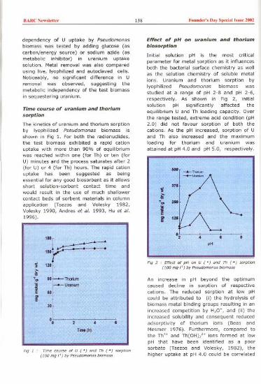
BARCN,w,I,"" 138 Found,,', Day Spedallss., 2002
dependency of U uptake by Pseudomonasbiomass was tested by adding glucose (ascarbon/energy source) or sodium azide (asmetabolic inhibitor) in uranium uptakesolution. Metal removal was also comparedusing live, lyophilized and autoclaved cells.Noticeably, no significant difference in Uremoval was observed, suggesting themetabolic independency of the test biomassin sequestering uranium.
Time course of uranium and thorium
sorption
The kinetics of uranium and thorium sorption
by lyophilized Pseudomonas biomass isshown in Fig 1. For both the radionuclides,the test biomass exhibited a rapid cationuptake with more than 90% of equilibriumwas reached within one (for Th) or ten (forU) minutes and the process saturates after 2(for U) or 4 (for Th) hours. The rapid cationuptake has been suggested as beingessential for any good biosorbent as it allowsshort solution-sorbent contact time andwould result in the use of much shallower
contact beds of sorbent materials in column
application (Tsezos and Volesky 1982,Volesky 1990, Andres et al. 1993, Hu et al.1996).
Effect of pH on uranium and thoriumbiosorption
Initial soiution pH is the most criticalparameter for metal sorption as it influencesboth the bacterial surface chemistry as wellas the solution chemistry of soluble metalions. Uranium and thorium sorption bylyophilized Pseudomonas biomass wasstudied at a range of pH 2-8 and pH 2-6,respectively. As shown in Fig 2, initialsolution pH significantly affected theequilibrium U and Th loading capacity. Overthe range tested, extreme acid condition (pH2.0) did not favour sorption of both thecations. As the pH increased, sorption of Uand Th also increased and the maximumloading for thorium and uranium wasattained at pH 4.0 and pH 5.0, respectively.
*1
41
F/g 2 .Effectof pH on U ( ') ,nd Th (.) ,o.pt/on(100 mg I') by P"udomon" b/om",
An increase in pH beyond the optimumcaused decline in sorption of respectivecations. The reduced sorption at low pHcould be attributed to (i) the hydrolysis ofbiomass metal binding groups resulting in anincreased competition by H30., and (ii) theincreased solubility and consequent reducedadsorptivity of thorium ions (Beas andMesmer 1976). Furthermore, compared tothe Th'. and Th(OH),h ions formed at lowpH that have been identifiedas a poorsorbate (Tsezos and Volesky, 1982), thehigher uptake at pH 4.0 could be correlated
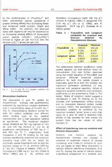
BARCN,w",U" 139 Found,,'s D,y Sp,d,llssn, 2002
to the predominance of [Th,(OH),]'. andother polymerized species possessing agreater binding affinity thus facilitating fasterand enhanced metal sorption (Gadd andWhite 1989). For uranium, the observedtrend with regard to pH may be explained byan increasing binding affinity of monovalenturanyl species (UO,OW, (UO,)o(OHh.)formed at higher pH (pH 4.0-5.0) over thedivalent (UO".) at low pH (pH 2.0).
Biosorption Isotherm
The biosorptive U and Th uptake byPseudomonas biomass was quantitativelyevaluated by equilibrium sorption isothermsover a concentration range of 0-1200 mg r'(Fig 3). Representative isotherm curves forboth the cations exhibited very efficientmetal binding even at low residualconcentration and a high saturation loadingat equilibrium. The maximum sorptionvalues obtained are 541 mg uranium g" drywt. and 430 mg thorium g" dry wt. atequilibrium concentration of 359 mg U I"and 885 mg Th r', respectively. Suchimpressive U and Th binding by the testbiomass significantly surpasses the economicthreshold level (15% dry wt. basis) forpractically usable biosorbents and so also theprevious values on Th [R. arrhizus (185 mgg" dry wt.) (Tsezos & Volesky 1981) or P.chrysogenum (3~8 mg g" dry wt.) (Gadd &White 1989)] and U [R.. arrhizus and
Penicillium chrysogenum (both 180 mg g")(Tsezos & Volesky 1981) P. aeruginosa CSU(110 mg g") (Hu et al. 1996), and M.smegmatis (44.5 mg g") (Andreas et al.1993)] uptake
Table 1 : Freundlich and Langmuirconstants for uranium andthorium sorption byPseudomonas biomass
The relationship between equilibrium metaluptake capacity (q) and residual metal ionconcentration (Ce) was further describedusing the model equation of Freundlich and
Langmuir. Although linearized sorptionisotherm for both the metals showed a
reasonably good fit to both the models, themaximum correlation coefficient (r) wasobtained with Langmuir equation. Values of
respective sorption constants and correlationcoefficients (r) are presented in Table 1. Thebetter fitting of Langmuir model suggest amonolayerd U and Th binding on to thebiomass with homogeneous surface energyand no interaction between sorbed metals
(Langmuir 1918). The asymptotic maximumadsorption capacity as predicted by theLangmuir constant 'qmax' gives a very highvalue for U and Th while a desirable high
affinity of the biomass for test metals areevident from the low values of otherconstant 'b'.
Effect of interfering ions on uranium andthorium biosorption
Uranium and thorium sorption byPseudomonas biomass was studied inpresence of equimolar amount of severalcompeting ions (Table 2). Selection of suchions are based on their likely occurrence inrealistic effluent interfering biosorption of Uand Th. Among the series of cations tested,a significant antagonism in U sorption was
Uranium ThoriumFreundlich k 199.00 159.20
l/n 0.206 0.176r 0.931 0.973
Langmuir qmax 555.5 476.19B 0.0027 0.0009r 0.997 0.998

BARC N'wsl"", 140 Found,,', Day Sp,dalls,n, 2002
Table 2 : Effect of interfering ions on Uand Th biosorption byPseudomonas
Init,,' UIThbwmos,
100 mg dm", pH 3,5,
offered only by thorium (IV), iron (II andIII), aluminium (III) and copper (II) whilemetals like cadmium (II), lead (II) siiver (II)and anions like chloride, phosphate andsulphate had no effect, The order of
inhibition to uranium binding by the cationswas Fe" >Th" >FeH >Cu" >AIH, Iron
(III), the cation considered as the most
potent competitor of uranium in bindingbiosorptive sites (Hu et ai, 1996), alsocaused a severe decline (80 %) in Uloading, Such inhibition to U sorption byFe", is a common phenomenon e,9, p,aeruginosa CSU (Hu et ai, 1996), R.. arrhizusand 5, levoris (Byerley et ai, 1987),Although AI" and AgH have also been found
to inhibit U adsorption by p, aeruginosa CSUand R, arrhizus, the Present Pseudomonasbiomass remained insensitive with respect toAgH, while AI" was significantlyantagonistic, Noticeably, in case of thorium,except iron (III), no other test cation showed
an inhibition more than 20%, Th sorptionwas insensitive to the presence of Na', CaH,
CdH, PbH, CO/', 50s" and CI, while theorder of inhibition by other cations isUO,"<CoH,<Ni2'<AI"<AgH<CuH, The
observed insignificant interference (only 8%inhibition) of U, on thorium binding can beattributed to a higher oxidation state of Thalong with additional bonding parameters(Andres et al.. 1993). Although, uranium andthorium biosorption by the present biomass
was fairly efficient in the presence of a rangeof cations, the role of Fe (III) in inhibiting Uand Th binding imposes serious limitations inwastewater treatment by this biosorbent.
Ideally, iron shouid be removed by pHadjustment or other methods prior tobiosorption.
(s)
(b)
(e)
Mechanism of biosorption and use ofimmobilized microbes in continuouscolumn reactors
Some studies have been undertaken to studythe mechanism of biosorption. Transmissionelectron microscopy of metal loaded cells
Percentage of sorptionUranium Thorium
Control 100 100
(onlyUorTh)Cations:
Na' 100 100
Ag" 98, 84"K' 98 86"Ca2' 98 100PbH 98 100Cd2, 96 100Cu2' 78" 83"AI" 82" 85"FeH 45" 57"Fe" 20" 60"Th" 37"
UO," 92Anions:
CI' 100 100
PO," 100
SO,' 100 100
COo' 74" 100',.".

BARCNe"""'" 141 Foond,,', Day Sped,,1 "'ne 2002
Conclusionrevealed an intracellular metal sequestration(Fig.4) with X-ray diffraction patternascertaining their phosphide nature. IRspectroscopy and NMR data suggests therole of cellular phosphoryl groups inradionuclide binding. For continuous use in acolumn the biomass was immobilized usingvarious techniques (D'Souza 1999b; D'Souza2001b; D'Souza 2002b) includingentrapment In radiation polymerizedacrylamide beads (Fig. 5). Scanning electronmicrograph of immobilized bacterial biomass(Fig.6) indicated no cellular damage/distortion during the immobilization process.The biomass could be used for repeated
sorption -desorption cycles in continuouscolumn operation. More than 90% ofbiomass bound U and Th was recoveredthrough elution using carbonates.
Fig 5' Immobilized Pseud,m,na, cell, a, bl, bead,
Fig 6 , Scanning electmn micmooopy ,r ImmobilizedPseud,mona, cell,
The overall study using the Pseudomonasstrain suggests the present biomass as apotential candidate for developing biosorbentfor uranium and thorium removal forwastewater remediation, however, a priorreduction of iron content is necessary. Aclear insight on the biomass U and Thbinding mechanism(s) and othertechnological parameters (currentlyunderway) will substantially improve itsfeasibility in process application.
Acknowledgements
The authors thank Dr (Ms) A. M. Samuel,Director, Bio-Medical Group, BARC, for herkeen interest in this work. Special thanks arealso given to Director, CIRCOT, Mumbai,Dr T Das, AIIMS, New Delhi and Mr. K.N.Harindran, UED, BARC for extending theirtechnical help in SEM, TEM and ICP analyses,respectively. Pinaki Sar acknowledges thefinancial assistance made by Board ofResearch in Nuclear Sciences, Department ofAtomic Energy, Govt. of India, in the form ofK.5. Krishnan post doctoral fellowship.
Reference
1. Andres Y, MacCordick H J and Hubert J C(1993) Adsorption of several actinide(Th, U) and lanthanide (La, Eu, Yb) ionsby Mycobacterium smegma tis. ApplMicrobial Biotechnol 39: 413-417.
2. Barkay T, Schaefer J (2001) Metal andradionuclide bioremediation : issues,considerations and potentials. CurrOpinion Microbiol.4 : 318-323.
3. Beas C F Jr and Mesmer R E (1976)Hydrolysis of cations. Wiley, New York.
4. Bhainsa K C and D'Souza 5 F (1999)Biosorption of uranium (VI) byAspergillus fumigatus. Biotechnol Tech13: 695-699.
5. Bhainsa K C. and D'Souza 5 F (2001a)Biosorption of Radionuclides and HeavyMetals by Fungal Biomass. in 'Industryand Environment', R. K. Trivedi, Ed.,Global Science Publications, Aligarh,India. pp. 149-155.
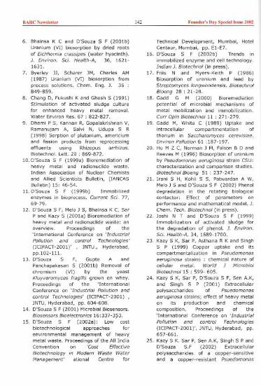
BARC N,w,l,tt" 142 Foond,,', Day Sp,dal hme 2002
6. Bhainsa K C and D'Souza 5 F (2001b)Uranium (VI) biosorption by dried rootsof Eichhornia crassipes (water hyacinth).J. Environ. Sci. Health-A, 36, 1621-1631.
7. Byerley JJ, Scharer JM, Charles AM(1987) Uranium (VI) biosorption fromprocess solutions. Chern. Eng. J. 36:B49-B59.
8. Chang D, Fukushi K and Ghosh 5 (1991)Stimulation of activated sludge culturefor enhanced heavy metal removal.Water Environ Res. 67 : 822-827.
9. Dhami P 5, Kannan R, Gopalakrishnan V,Ramanujam A, Salvi N, Udupa 5 R(1998) Sorption of plutonium, americiumand fission products from reprocessingeffluents using Rhizopus arrhizus.Biotechnol. Lett. 20 : 869-872.
10. D'Souza 5 F (1999a) Bioremediation ofheavy metal and radionudide waste.Indian Association of Nudear Chemists
and Allied Scientists Bulletin, (IANCASBulletin) 15: 46-54.
11. D'Souza 5 F (1999b) Immobilizedenzymes in bioprocess. Current Sci. 77,69-79.
12. D'Souza 5 F, Melo J 5, Bhainsa K C, Sar
P and Kazy 5 (2001a) Bioremediation ofheavy metal and radionudide waste: anoverview. Proceedings of the'International Conference on 'Industrial
Pollution and control Technologies'(ICIPACT-2001)' , JNTU., Hyderabad,pp.l02-111.
13. D'Souza 5 F, Gupte A andPanchapakesan 5 (2001b) Removal ofchromium (VI) by the yeastKluyveromyces fragilis grown on whey.Proceedings of the 'InternationalConference on 'Industrial Pollution and
control Technologies' (ICIPACT-2001) ,JNTU, Hyderabad, pp. 604-608.
14. D'Souza 5 F (2001) Microbial Biosensors.
Biosensors Bioelectronics 16:337-3?3.15. D'Souza 5 F (2002a): Low cost
biotechnological approaches forenvironmental management of heavymetal waste. Proceedings of the All IndiaConvention on 'Cost Effective
Biotechnology in Modern Waste WaterManagement' ational Centre for
Technical Development, Mumbai, HotelCentaur, Mumbai, pp. EI-E7.
16. D'Souza 5 F (2002b) Trends in
immobilized enzyme and cell technology.Indian J. Biotechnol (in press).
17. Friis N and Myers-Keith P (1986)Biosorption of uranium and lead byStreptomyces longwoodensis. BiotechnolBioeng 28 : 21-28.
18. Gadd G M (2000) Bioremediationpotential of microbial mechanisms ofmetal mobilization and immobilization.
Curr Opin Biotechnoll1 : 271-279.
19. Gadd M, White C (1989) Uptake andintracellular compartmentation ofthorium in Saccharomyces cerevisiae.Environ Pollution 61 :187-197.
20. Hu M Z C, Norman J M, Faison B D andReeves M (1996) Biosorption of uraniumby Pseudomonas aeruginosa strain CSU:characterization and comparison studies.Biotechnol Bioeng 51: 237-247.
21. Irani 5 H, Kohli 5 5, Patwardan A W,Melo J 5 and D'Souza 5 F (2002) Phenoldegradation in the rotating biologicalcontactor: Effect of parameters onperformance and mathematical model. J.Chem. Tech. Biotechnol (in press).
22. Joshi N T and D'Souza 5 F (1999)Immobilization of activated sludge forthe degradation of phenol. J. Environ.Sci. Health-A, 34, 1689-1700.
23. Kazy 5 K, Sar P, Asthana R K and Singh5 P (1999) Copper uptake and itscompartmentalization in Pseudomonasaeruginosa strains: chemical nature ofcellular metal. World J MicrobiolBiotechnol15 : 599- 605.
24. Kazy 5 K, Sar P, D'Souza 5 F, Sen A.K,and Singh 5 P (2001) Extracellularpolysaccharides of Psuedomonasaeruginosa strains; effect of heavy metalon its production and chemical
composition. Proceedings of the'International Conference on 'Industrial
Pollution and control Technologies
(ICIPACT-2001)', JNTU, Hyderabad, pp.657-661.
25. Kazy 5 K. Sar P, Sen A.K, Singh 5 P andD'Souza S.F (2002) Extracellularpolysaccharides of a copper-sensitiveand a copper-resistant Psuedomonas

BARCN""I,Uer 143 Found,,', Day Sp,dall",uc 2002
aeruginosa strains: synthesis, chemicalnature and copper binding. World J.Microbiol Biotechnol18 : 583-588.
26. Langmuir I (1918) The adsorption ofgases on plane surfaces of glass, mica,and platinum. J. Amer. Chem. Soc. 40 :1361-1403.
27. Lloyd J R, Macaskie L E (2000)Bioremediation of radionuclide-
containing wastewaters. In : Lovely DR,eds, Environmental Microbe-MetalInteractions. Washington DC : American
Society of Microbiology, pp. 277-32728. Melo J 5 and D'Souza 5 F (2001)
Biosorption of uranium and thorium byagro based biomass. Proceedings ofTenth National Symposium on'Environment' BARC Mumbai, pp. 293-296.
29. Panchapakesan, S, Melo, J S, Bhainsa, KC and D'Souza, S F (2002) Glucose
dependent accumulation of cadmium bya metal tolerant yeast. In 'Applicationsof biotechnology for clean environmentand energy'. (G. Bali Ed) OxfordPublications, pp. 199-212.
30. Sangurdekar P R, Melo J Sand D'Souza
S F (2001) Biosorption of radioactivecobalt and cesium using mucilaginousseeds. Proceedings of Tenth National
Symposium on 'Environment' BARCMumbai, pp. 298-299.
31. Sar P, Kazy S K, Asthana R K and SinghS P (1998) Nickel uptake byPseudomonas aeruginosa : Role ofmodifying factors. Current Microbiology37: 306-311.
32. Sar P, Kazy 5 K, Asthana R K and SinghS P (1999) Metal adsorption anddesorption by lyophilized Pseudomonasaeruginosa." Int. Blodeterior. Biodegr.44: 101-110.
33. Sar P and D'Souza 5 F (2001a)Biosorptive uranium uptake by a
Pseudomonas strain: characterization
and equilibrium studies. J. Chem. Tech.Biotechnol76: 1286-1294.
34. Sar P and D'Souza S F (2001b)
Radionuclide biosorption by bacterialbiomass. Proceedings of the'International Conference on 'Industrial
Pollution and control Technologies'
(ICIPACT-2001)', JNTU, Hyderabad, pp.651-656.
35. Sar P, Kazy 5 K and Singh 5 P (2001a)Intracellular nickel accumulation byPseudomonas aeruginosa and itschemical nature, Lett. Appl. Microbiol.32: 257-261.
36. Sar P, Kazy 5, Singh S P and D'Souza SF (2001b) : Radionuclides and heavymetal biosorption by Pseudomonasbiomass. Proceedings of Tenth NationalSymposium on 'Environment' BARCMumbai, pp. 218-222.
37. Sar P and D'Souza S.F (2002)
Biosorption of thorium (IV) by aPseudomonas strain. Biotechnol Lett,24: 239-243.
38. Shanmugam K, Subrahmanyam S,Tarakad S V. Kodandapani NandD'Souza S F (2001) 2,4-toluenediamines Their carcinogenicity,biodegradation, analytical techniquesand an approach towards developmentof biosensors. Analytical Sciences
(Japan) 17: 1369c137439. Tsezos M and Volesky B (1981)
Biosorption of uranium and thorium,Biotechnol Bioeng 23 : 583-604.
40. Tsezos M, Volesky B (1982) The
mechanism of thorium biosorption byRhizopus archizus. Biotechnol. Bloeng24: 955-969.
41. Volesky B (1990) Biosorption of heavymetals, ed by Volesky B, CRC Press,Boca Raton, FL, pp 7-44.
This paper receh'ed the Best Presentation award at the International Conferenceon 'Industrial Pollution and Control Technologies(ICIPACT-2001)', held atJawaharlal Nehru Technological Universi~v, Hyderabad, duringDecember 7-10, 200I
BARC New,'ett" 144 Fouud,,', Day Spedall"ue 2002
About the authors ...
Dr Pinak' Sar obtamed hi, Ph.D. in Botany toe thi, theoi" "Invewgation on "'eudomona> aewgino,aa> bioaccumulato, of nickel" fmm Banaea, Hindu Unive"ity. He Wa> the ,eeipient of 0, K.S. Kn,hnanR"ea"h A«ociate, 2'" batch and wo,ked in the acea of eadionutlide bio,emediation at BARC Cu,cently,he is a fatUity membee at the Bida In,titote of Tethnology and Science. He ha, to hi, teedit >evenpape" in intemationally ceputed joumals and live pape" in intemational and national confecentepmeeeding'. Hi, field of ce>ea"h intece,t i, on metal/eadionue/ide and o,ganit pollutant biocemediation.
0, S.F. D'Souza g,aduated fmm the 15'" batch ofthe T,aining School (Biology &tU"ently the Head of the Nue/ea, Ageicultuce and Bioteehnology DMsion of BARC Hi,intecest has been in the field of En'yme and Miteobial Bioteehnology with"immobilized cell, foe u,e in biopmce«ing, bio>enso" and biocemediation. He ha> t,scientific pape" and invited ceviews in ,eputed Intemational/Natmnalmembe,/expect at National Scientifit committe,,; membee of the editoeialand has been to deli,., talks/key note lettuces, chai, scienWic >e«ion, at ",iousfowm,. He has cont,ibuted significantly to "ience education a> an invited
National wo,kshops and shoet teem cou"e, a> well as UGC Refce,he, cou"es, as an invit,Ph.D., M.St. examinee (Univ/IIT) and a> a membee of the baaed of studie, and ce>ea"hguided a numbee of ,tudent> fa, Ph.D. and M.St. He"his ,ignfficant cont,ibution, to the field of MicmbiologyScience (1993), Fellow of the A«ociation of Food Scientist>Aeademy of Science (2001).
BARC Ne"sle"" 145 Foood,,'s Day Spedal Issoe 2002
Molecular Characterization of ex-typeStrains of Trichoderma spp. from twoIndian Type Culture CollectionsJ. Latha and Prasun K. Mukherjee
O"'s'oe
Abstract
<so/,teo was ""tly the same as r. hamatum iso/ateo ie
the need fo, ,e-examinat,"n and ce-,/asom"tion of r.,ichadeema sppwl/ections
Introduction
Species in the fungal genus Trichoderma(Ascomycetes, Hypocreales) are of greateconomic importance as sources of enzymes,antibiotics, as plant growth promoters,xenobiotic degraders, and most importantly,as commercial biofungicides (Mukherjee,1999). Two species (T. longibrachiatum andT. citrinoviride) are also known to beopportunistic pathogens on Immuno-suppressed patients (Kuhls et ai, 1999).Until recently, Trichoderma spp. were beingidentified based on morphological data likecultural characteristics, structure ofconidiophores/ conidia, ete. (Rifai, M.A.,1969; Bissett, J., 1984, 1991a, 1991b,1991c, 1992). However, subsequentmolecular analysis of several strains,including some ex-type strains revealed that
classification based on morphological datahave been, to a great extent, erroneous
resulting in re-classification of severalisolates and species (Meyer et al. 1994;Rehner et al. 1994; Kuhls et al. 1996, 1997;Bulat et al. 1998; Castle et al. 1998;Kindermann et al. 1998; Lieckfeldt et al.
1999; Hermosa et al. 2000). For example,three Indian isolates of Trichoderma, thatare deposited at Microbial Type CultureCollection, Chandigarh, as T. harzianum,were examined by Hermosa et al. 2000. Twoof them were found to be T. inhamatum, andone was classified as T. longibrachiatum,using molecular tools. Correct identificationof Trichoderma spp. is important both fromcommercial point of view (as several traitsare species-specific), and from safety pointof view. This is particularly important for thetype cultures as these are used by several
workers and are taken as authentic samples.We therefore examined some representative
isolates of this commercially importantfungal genus using two PCR-basedtechniques viz. RAPD- Random Amplificationof Polymorphic DNA, and restriction analysisof the amplified ITS1-S.8S-ITS2 region ofthe nuclear ribosomal DNA.
Materials and Methods
Two isolates each of six species ofTrichoderma (T. virens, T. pseudokoningii,T. hamatum, T. harzianum, T. virid" and T.
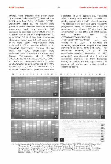
BARC N'w,I,.." 146 Found,,', Day Sp,dal b,n, 2002
koningii) were procured from either IndianType Culture Collection (ITCe), New Delhi, orthe Microbial Type Culture Collection (MTCC),Chandigarh (Table I), The isolates were
grown in potato dextrose broth at ambienttemperature and total genomic DNAextracted as described earlier (Mukherjee, p,K, 1999), For all the PCR amplifications, 50
ng of DNA, 0,5 U of Taq DNA polymerase(Bangalore Genei) and 0,1 mM each of thedNTPs were used, Amplifications wereperformed in 25 "' reaction volume in anEppendorf Mastercycler Personal thermalcycler. For RAPD, amplifications wereperformed with 5 random decamers fromOperon Technologies kit A (OPA1-CAGGCCCTTC, OPA2- TGCCGAGCTG, OPA3-AGTCAGCCAC, OPA4-AATCGGGCTG, OPA9-CGGTAACGCC) at 37°C annealing (I'), 94°Cdenaturation (I') and 72°C extension (2') -
35 cycles, Amplification products were size
M1234567 B 9 10 11 12
separated in 2 % agarose gel, visualizedafter staining with ethidium bromide andphotographed with a UVP polaroid camera,The isolates were clustered using TreeconWprogramme based on binary score for thepresence (1) or absence (0) of a band. Foramplification of the ITSI-5.8S-ITS2 region,the primer pair ITSI(TCTGTAGGTGAACCTGCGG) ITS4(TCCTCCGCTTATTGATATGe) was used(White et ai, 1990), To optimize theannealing temperature, amplifications wereperformed at 56°C, 58"C and 59"c. Forrestriction analysis, 20 "' of theamplification-product (amplified at 59"Cannealing) was digested with 5 units ofrestriction enzymes (all from BangaloreGenei) for 2 hours and size separated in 2 %agarose gel, stained and photographed asdescribed above,
M 1 2 3 4 5 6 7 8 9 10 11 12

BARC Nowslener 147 Founder's Day Special wue 2002
Results and Discussion 12 3 4 5 6 7 89 101112M
RAPDanalysisbased on 5 random primers(selected out of 10 primers after an initialscreening) revealed a great deal of intra-and inter-specific variability amongstTrichoaerma isolates examined except forthe two T. hamatum isolates that wereexactly identical (Fig. I). Surprisingly, one T.koningii isolate (TK2) was also exactlyidentical to both the T. hamatum isolates.The RAPDfingerprinting data (Fig. I) clearlyindicate that there is mixing-up as far asspecies identification is concerned. Forexample, T. harzianum isolate no. 1 clusterswith T. viride isolate no. I, while T.harzianum isolate no. 2 clusters with T.viride isolate no. 2. Similarly, T. viren5isolate no. 1 is more close to T. koningiiisolate no. I, than to T. viren5 isolate no. 2,while T. pseudokoningii isolate no. 2 is moreclose to T. hamatum isolates, than to T.pseudokoningii isolate no. 1. Since RAPDisoften considered to be less reliable thanRFLPdata, we also analyzed the RFLPin theamplified ITSI-5.8S-ITS2 region. Anannealing temperature of 59°C was found tobe suitable for the amplification of ITSI-5.8S-ITS2 region from all the isolates withgood product yield and minimum non-specific amplifications. The product size wasapproximately 600 bp, and there was sizevariation across the isolates (Fig. 2). At allthe three annealing temperatures, we couldsee two bands only with the T. viride isolateno. 1. Digestion of this product with fivetetra-base cutters (Mbol, Haem, Taql,Sau3AI, M5pI) revealed polymorphism in theITSI-5.8S-ITS2 region (Fig 2). All theisolates could be grouped into broadly fourgroups (Table 2), which again showed theoverlapping in species identification of thesestrains, e.g., T. p5eudokoningii isolate no. 2,and T. koningii isolate no. 2 grouped with T.hamatum isolates.
The present analysis questions the identity ofTrichoderma isolates maintained in two ofthe Indian type culture colleclions. This isnot surprising given the fact that these wereidentified using morphological data, which,as a taxonomic tool for Trichoderma spp.,has been confusing. It is therefore, proposed
A
.' "~"'. ::2::-
c -..;..--.--..-----~~4': ...=:---,.
Hg. 2 . Analysis of the ITSl-5.85-ITS2 region of theTrichode""a isolates (Lanes 1= T. vkens I, 2=T. vi~ns2, 3= T. pseudokoningil " 4= T. pseudokoningil 2, 5=T. hamatum " 6= T. hamatum 2, 7= T. harzianum "8= T. harzlanum 2, 9~ T. vlride 1,10= T. vlrlde 2,11=T. konlngil " 12= T. koningil 2. M~ Molecular weightmarker). A= amplification" 56 C, B= amplification at58 C, C~ amplification at 59 C, D~ digestion of thelT51-5.85-ITS2 region with HaeIII, E= digestion of theITSl-5.85-ITS2 region with Mspl.
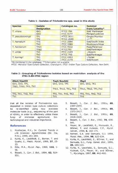
BARC Newslett" 148 Founder's Day Special Issue 2002
Table 1 : Isolates of Trichoderma spp. used in this study
*As mentioned in the catalogue; **Info""ation not avaHable
MTCC- Microbial Type Cuiture Collection, Chandigarh; !TCC- Indian Type Culture Colledion, New Delhi.
Table 2 : Grouping of Trichoderma isolates based on restriction analysis of theITSl-S.8S-ITS2 region
that all the isolates of Trichoderma spp.deposited in Indian type culture collectionsbe fe-Identified using now availablemolecular tools (e.g., sequencing of the partof rDNA), in order to effectively utilize thesefungi of immense agricultural, bio-technological and industrial importance.
References
1. Mukherjee, P.K., In: Current Trends inUfe Sciences- Agromicrobes (Ed. Jha,M.N.), 1999, 261-280.
2. Kuhls, K., Lieckfeldt, E., Borner, T. andGueho, E., Medic. Myco/., 1999, 37, 25-33.
3. Rifai, M.A., Myco/. Pap., 1969, 116, 1-56.
4. Bissett, J., Can. J. Bot., 1984, 62, 924-931.
5. Bissett, J., Can. J. Bot., 1991a, 69,2357-2372.
6. Bissett, J., Can. J. Bot., 1991b, 69,2373-2417.
7. Bissett, J., Can. J. Bot., 1991c, 69,2418-2420.
8. Bissett, J., Can. J. Bot., 1992, 70, 639-641.
9. Meyer, W., Lieckfeldt, E., Morawetz, R.,Barner, T. and Kubicek, cP., Mycoi.Helvet., 1994,6, 160-171.
10. Rehner, S.A. and Samuels, G.J. 1994,Hycol. Res., 1994, 98, 625-634.
11. Kuhls, K., Lieckfeldt, E., Barner, T., andSamuels, G.J., Fung. Genet. BioI., 1996,20, 105-114.
12. Kuhls, K., Lieckfeldt, E., Samuels, G.J.,Kubicek, C.P., Meyer, W., and Barner,T., Mycoiogia, 1997,89,442-460.
Species Isolate Catalogue no. IsolatedDesianation from/Locality'
T. virens GVl MTCC794inGV2 ITCC4177
T. pseudokoningii TPI MTCC 3011i,,9.er/MumbaiTP2 MTCC2049
T. hamatum THI !TCC2084h/i:rTH2 !TCC3380
T. harzianum THzl !TCC4532 PeaslPalampurTHz2 MTCC792 Soil/Pantnaaar
T. viride TVI !TCC2109 -/AssamTV2 MTCC793 Soil/Pantnanar
T. koningii TKI !TCC4303 -/Solan- TK2 !TCC2170 SoillAssam
MboI HaeIII TaoI Sau3AI MSDIGVl. GV2, TPl, GVl, GV2, TPI GVl, GV2, TKITHzl THz2 TKI TV2
THzl, THz2, TKl, TV2 THzl, THz2, TPl,TV2
TP2 THI TH2 TK2 TP2 THI TH2 TK2 TP2 THI TH2 TK2TVI TVI TVI

BARCN,w,',"" 149 Fonnd,,', Day Sp,da' ["n' 2002
13. Bulat, SA, Lubeck, M., Mironenko, N.,Jensen, D.F., and Lubeck, P.5., Mycol.Res., 1998, 102,933-943.
14. Castle, A., Speranzini, D., Rghei, N.,Aim, G., Rinker, D. and Bissett, J., Appl.Env. Microbial., 1998, 64, 133-137.
15. Kindermann, J., EI-Ayouti, Y., Samuels,G.J. and Kubicek, CP., Fung. Genet.Bioi., 1998,24,298-309.
16. Lieckfeldt, E., Samuels, G.J., Nirenberg,H.!. and Petrini, 0., Appl. Env.Microbial., 1999, 65, 2418-2428.
17. Hermosa, M.R., Grondona, I., Iturriaga,E.A., Diaz-Minguez, J.M., Castro, C,Monte, E., and Garcia-Acha, I., Appl.Env. Microbial., 2000, 66, 1890-1898.
18. Mukherjee, P.K., As-Pac. J. Mol. Bioi.Biotechnol. 1999,7,95-96.
19. White, T.J., Bruns, T., Lee, S. andTaylor, J., In: PCR Protocols. A Guide toMethods and Applications (Eds. Innis,M.A., Gelfand, J.J., Sninsky, J.J. andWhite, T.J.), 1990, 315-322.
This paper received the Best Poster Award at the tdh Annual Meeting of theSociety of Biological Chemists (India), held at Dept. of Biochemistry, OsmaniaUniversity, Hyderabad, during December 27-29,2001.
About the authors ...
Ms J. Latha, M.Sc (Biotechnology), i, fcom the 42" botch of BARC Tcaining School. She is the cecipientof the "Homi Bhabha Awaed" foe Biology-Radiobiology discipline in he; batch, and is woeking in the PlantPathology and Pesticide Residues Section of Nucleae Agdeultuce and Biotechnology Oivision (NABTO).
Dr P. K. Mukheojee, M.Sc (Ageieultvce), completed his Ph.O. as a Keishnan DAE ceseaceh fellow. He iswoeking in the Plant Pathology and Pesticide R"idv" Section of Nvc/eae Ageicvltvce and BiotechnologyOivision (NABTO), on the biocontcol mechanisms of plant diseases. He was awaeded the "Pean VoheaAwaed" foe ageicvltveal sciences dueing 1998-1999 by the Indian Science Congcess Association.

BARC New,]ett" 150 Found,,', Day Speda""ue 2002
Sensor for Remote Detection of Eccentricitybetween Coaxial Metallic Tubes
T. V. Shyam, S. K.Apraj and B.S.V.G.SharmaR'octoc Engineeeing Divi,ionShabh, Atomic R","coh Ceotce
Background
Precise measurement and correction of
eccentricity between the two co-axialmetallic tubes is essential in many industrialfields. One of such requirement in Indiannuclear reactors is need to measure and
correct the eccentricity between highlyradioactive non ferrous low electrical
conductivity metallic tubes. An eddy currentsensor based transducer and its associated
hardware has been designed in order tocheck the eccentricity between metallic tubesin vertical axis ('Y' direction). These tubesare initially eccentric which needs to becorrected by using a Tube Flexing Tool(TFT). The sensor needs to be mounted in
one of the bearings of TFT as an integralpart of the tool, which will be inserted inthe bore of inner tube. The TFT is
hydraulically actuated in 'Y' directiongenerating vertical thrust to correct theeccentricity between the metallic tubes
based on the eccentricity information feedback received from the transducer. This
transducer needs to be operated from 100
meters cable distance and should be fairlyinsensitive to the lift-off errors. Further,since the TFT is subjected to very high
Abstract
mechanical stresses during eccentricitycorrection operation, the sensor needs to beprotected against the damages. Thetransducer dimensions should be fairly smallenough to fit in the bearing housing of TFT.The design constraints, constructionalfeatures and performance evaluation of thetransducer system has been described infollowing sections.
Design Constraints And SalientFeatures
a) Mounting: The sensor being the integralpart of the eccentricity correction tool TFTneeds to be mounted in the bearing housingof the tool. The transducer should be
designed such that the magnetic fluxemerging out of the sensor should link the
coaxial metallic tubes. The metallic body ofTFT should not divert the flux. In order toachieve this, 'C-clamp type pancake probeshave been designed to ensure the fluxlinkage to both the tubes in spite of sensorsbeing embedded in the tool bearing.b) Size: The sensor size should be small
enough to fit in the bearing ofTFT.c) Sensitivity: The sensor should be enoughsensitive to detect precisely the eccentricity

BARC New"en.. 151 Found..', Day Spoolal b,ue 2002
between the metallic tubes. In order toimprove the sensitivity of the sensor, theooL/R ratio of the coii should be high.Mumetal has been used as the sensormaterial. One can also use ferrite core toimprove the sensitivity, however mumetalhas been used for higher sensitivity andbetter strength.d) Tool Bearings: In order to reduce thediversion of flux generated in the sensorwhich is embedded in the bearing housing,the metallic bearings cannot be used forTFT. Non metallic high crushing strengthPhenolic bearings have been used to servethe purpose. The sensor is embedded in oneof the phenolic bearings and is protected bysuitable potting.e) Operating environment: The sensorsystem should be capable to work in RF!andEM!noisy environment.
Constructional FeaturesSystem Configuration
The schematic of the eccentricitymeasurement transducer sensor is shown inFig.! The transducer works on eddy currentprinciple. The parameters such asconductivity, permeability, dimensions of the
test object, spacing between the test objectand test coil, spacing between the testobjects and test frequency affecting eddycurrent are phase sensitive. It has beenseen that the parameter like lift-off is lessphase sensitive as compared to parameterslike thickness variation and spacing betweenthe components. In order to nullify the lift-off error, the phase measurement techniquehas been used in the system instead ofamplitude measurement technique since thelater is more sensitive to lift-off errors.
And
The eccentricity detection transducer consistof two eddy current sensors embedded in thebearing of the TFT. The sensors are locatedat 3 O'clock and 12 O'clock positions on theperiphery of the bearing. The sensor at 3'0'clock position is used as reference sensor.The sensor in 12 0' clock position is used asthe measurement sensor. These sensors areconfigured in differential mode by which thethickness variation and temperaturevariation of tube which in turn affects theconductivity will be compensated. Byconfiguring the sensors in differential modethe common mode signals have beennullified.
[
INNER METAWelUBE
Fig. 1 .. Schematic of eccent,icity detection tran,duee.
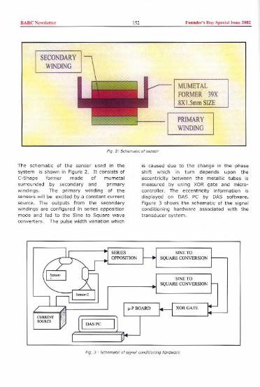
BARC New,'e"" '52 Found,,', D,y Sped,""ue 2002
Fig. 21 Schema"c of <en",
The schematic of the sensor used in the
system is shown in Figure 2. It consists ofC-Shape former made of mumetal
surrounded by secondary and primarywindings. The primary winding of thesensors will be excited by a constant currentsource. The outputs from the secondarywindings are configured in series oppositionmode and fed to the Sine to Square waveconverters. The pulse width variation which
is caused due to the change in the phaseshift which in turn depends upon theeccentricity between the metallic tubes is
measured by using XOR gate and micro-controller. The eccentricity information isdisplayed on DAS PC by DAS software.Figure 3 shows the schematic of the signalconditioning hardware associated with thetransducer system.
Fig. 3 I Schematic of 'i9nol conditioning hacdwace

BARC Newsletter 153 Found,,'s Day Spedall"ue 2002
Table-lUft...ff conbibution Versus Frequency
2-L8.
Pressurels'ainIConductivnyaffecingparameter)ve~usPhaseang'e
-~:
//,//
;;
j::mn
.. ,. ..TFT!OOLP",ssu",
Table 2
,51No.
~bb"3.~5.6.L,8.
11d,12
Eccentricity)@riation in m:2~2-.:1-3~.:.1.L+1+2+3+4+5+6+7+8':16.
~~
t~"~ v//
""""""""""""",,
SENSORPERFORMANCEATVARYOG51RfSSES
.;~ .m..,..,""~I"'"
'.,00
, ,"",tr;,;Iy;,mm.
PhaseangleVersusEccentricity
.;~ 'M,- '",! "'": ""[ ..
.//,/.~/
" . ,""",,,,;t",mm,

BARCN,w,I,"" 154 Found,,', Day Sp,dal "m, 2002
Experimental Observations UsingPrototype System
The prototype transducer system developedhas been used to measure the effect of liftoff error at various frequencies in order tooptimise the operating parameters for thetransducer system. The Phase anglevariation of signal while varying the fullrange of eccentricity between the tubes (0 to16mm) for a typical setup have beenstudied.
(a) The results of Test Frequency Vs Worstpossible Lift Off % is given in Table-I.
(b) The results of Eccentricity (-8 mm to+8mm) variation verses Phase anglevariation is given in Table-2.
The following observations have been noted:
(a) Lift-Off Error: By using phasemeasurement techniques, the para-meters like lift off are less sensitive. The
parameter like annular gap variationbetween the tubes is more predominant.
(b) Transducer Signal Variation Due ToEffect Of Mechanical Stress on Tubes: Ithas been observed that when TFT is
operated to correct the eccentricitybetween the metallic tubes, themechanical stresses are generated inthe inner metallic tube due to flexing.These stresses will affect the signal output of the transducer. As such the signalcontribution due to the affect ofmechanical stress generated in the tubeshould be compensated by using look-uptable or by going for multi parametertechnique.
Conclusion
The prototype of the transducer has beenfabricated and tested. The experimentalresults are found highly encouraging. Thetransducer can be operated from a distanceof 100 meters. Its performance is leasteffected by lift off errors. It has beenobserved that by using high permeabilitypancake probes, intense magnetic fluxes canbe produced and application where remotefield in non ferrous tubes is used, this type of
design is having advantage.
Schematic ofPHWR Coolant Channel
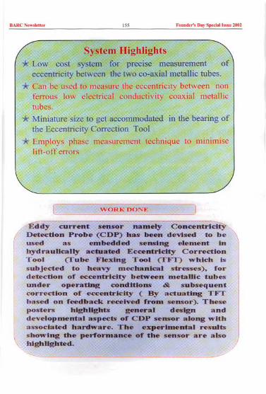
BARC New,'e"er 155 Founder', Day Spedal I".e 2002

BARCN,w,l,"" 156 Found,,', Day Sp,dal "me 2002
Tube Flexing Tool (TFT) Modules used in Typical Tool
A typicaltwo coaxiin order toC coolantvertical a,eccentric,
Flexing T~oC the bealThe TFTin the bolactuatecorrecton the ethe tran,
between theed and usedletallic tubesPHWR's inare initially
using a Tubeounted in oneof oC the tool.II be inserted
hydraulically:ical thrust to'0 tubes based'eceived Crom

BARe Newslett" 157 Foood,,'s Day Speelallssoe 2002
,,!tHn \, PI
CHANICAL THRUST TOICORRECT ECCENTRICITY
OUTER METALLIC TUBE
SENSORS
)i]I",

BARC Now,',"" 158 Found,,', DaySp,dal '"U, 2002
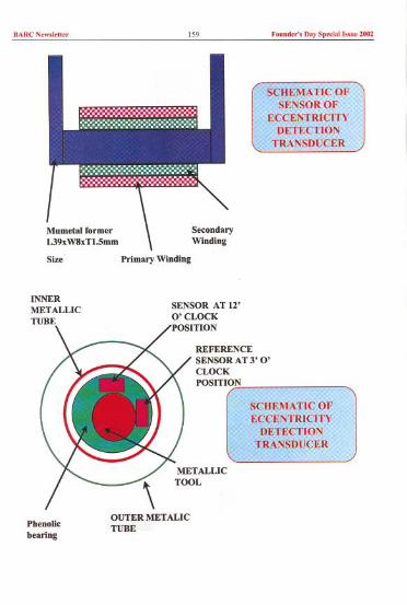
BARC New,]ett" 159 Found,,'s Day Speda! Issne 2002
SecondaryWinding
Size Primary Winding
SENSOR AT 12'O'CLOCKPOSITION
REFERENCESENSOR AT 3' 0'CLOCKPOSITION
Pbenolic
bearing
OUTER METALICTUBE

BARC New,lett" 160 Found,,', Day Spedal I"ue 2002
PS -PRIMARY START
PE - PRIMARY END
SS-SECONDARY START
SE - SECONDARY ENDPRJMARY EXCITATION
GNDSENSOR AT 12'O'CLOCKPOSITION (SI)
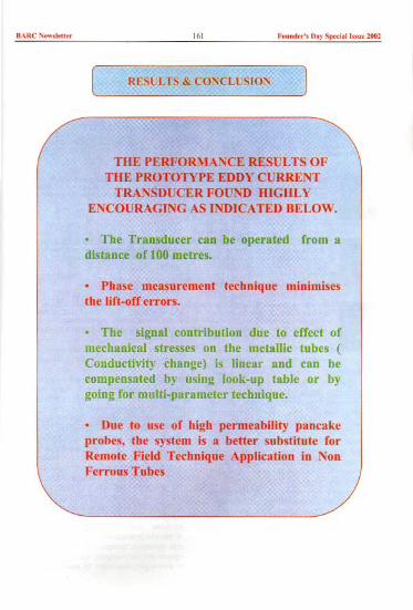
BARC New,'e"" 161 Found,,', Day Speda1 "sue 2002

BARCNewslett" 162 Foond,,'s Day Spedal Is,ne 2002
This paper received the Best poster presentation award at the 8'" National Seminaron "Physics and Technology o.{Sensors" held at BARC, Mumhai, duringFebruary 27 - March 1, 2001
About the authors ...
Mr T.V. Shyam " acti,eiy wo.king on and development of w..ent "nooco a»ociated, conditiomng ciccuit, and beoed 'y,tem, which ace u"d in cehabilitationfa. cepai.. and life-exten,ion ceplacement of coolant channel, of Indian Hea'y Wate.
Reactoco.
on fab.ieation of ,".iou, eowciatedwhich ace being u,ed m tool, cepaic.
Pce»u,i"d Hea,y Water Reactoco.
Mr S.K. Apraj i, acti,elyconditioning ci,wit, and contcol
Leadce. ElecteicalO"ice, &Automation Reactoe Coolant ChannelDiYi,ion He heo taken a leading cole in and of
Line" Induction 110toco.in,tcumentation and 'y,tem, foe, cequi.ed foe in ""ice in,pection. cepai,. life exten"on and .eplacementPce»u,i"d Heavy Water Reactoco.

BARCN,w,l,"" 163 Found,,', Day Sp,dall",u, 2002
Synthesis of Chalcogenolate Complexes ofPlatinum Group Metals as MolecularPrecursorSandip DeyNo,,' M,'ee',lo&S'coctcco'Chemi,t,y°""'°0Bh,bh,Atomia""e",h Ceot,e
Introduction
Materials gcowth techniques like MOCVO,plasma CVD, etc. employ molecula,
precursors rather than the elements tosynthesize low temperature solid stateinorganic materials for electronic devices [I].During the last decades platinum gcoupmetal chalcogenolates have attractedconsiderable attention as molecular
precursors for the synthesis of metalchalcogenides for electronic devices [2J. Thearea of metal chalcogenolates has beendominated by thiolato complexes which inmost cases have been isolated as non-
volatile, insoluble (sparingly soluble) andpolymeric complexes thus making theminconvenient as precursor for the preparationof metal chalcogenide [3J. To suppresspolymerization several strategies have beenexplored such as, (a) strongly coordinatingligand such as tertiary phosphines, (b)
sterically demanding chalcogenolate ion, (c)internally functionallised ligands containing
both soft chalcogen and hard N donors [4-6].The later class of ligands not only yield lownuclearity complexes but also enhancecomplex stability. With the current interest in
selenium containing inorganic materials andin pursuance of our program on the designand development of molecular precursors in
Abstract
NM&SCD, BARC, dibenzyl diselenide (Bz,Se,)and 2-dimethylaminoethyldiselenide (Me,NCH,CH,Se), were prepared and theirpalladium and platinum chemistry wasexplored.
Discussion
1 (i) Synthesis and characterization ofbenzylselenolate complexes
Sodium benzylselenolate has been preparedby the reductive cleavage of the Se-Se bondin Bz,Se, (due to slow photo-decompositionit was recrystallised every month frompetroleum ether) with NaBH, and thefollowing Pd(II)/Pt(II) complexes have beenprepared (scheme 1) [7]. The compound isa sparingly soluble polymeric complex.Strong neutral donor ligands like tertiaryphosphines can easily cleave the selenolatobridge of 1 with the formation of monomericcis isomer 2. In the case of binuclearcomplexes (4-6) three isomers, viz. onetrans and two cis isomers are posiible.
On the basis of NMR spectlOscoPy, except infew cases, binuclear complexes (4-6) wereformed exclusively as a cis isomer.
The "Se NMR spectrum of [Pt2C12(~-
SeBz),(PPro,),J (Fig 1) shows that two Se

BARC New"eU" 164 Found,,'s Day Spedal Issue 2002
cis- [M(SeBz),(JY'P)l (2)
V'Pj[M(SeBzhl. (I)
(M~ Pd; Pt)
-+ [MaX,{,,-SeBz),(PR,hJ (4)
(X~CI,Me)
[M"Cla(,,-SeBzhfPR.hl + [MaCIa(,,-CIMPR.hJ
.[M,CI,(,,-CI){,,-SeBz)(PR,),1 (5)
y .
MCIa(JY'P) + 2NaSeBz
(JY'P ~ dppm. dppe. 2PPha)
M',MC4 + 2NaSeBz
[MaCI,«,,-ClhfPR.hl + 2NaSeBz
trans- [PtIa(PPhahJ (3)
Mel exeess .t--.-.
[M"CI,{,,-Y}{,,-SeBz)(PRahl (6)(y - pz. SBu')
D~~" ,
F'9 1 "Se NNR 'pcacum of [ PWd" SeB'MPP~,hJ
atoms are magneticaOy in-equivalent, one istrans to P atoms and other is trans to
chlorides. The X-ray structure of thiscomplex (Fig 2) revealed that it consists of
two distorted square planar platinum atomsPt(l) and Pt(2) which show deviation of0.046 and 0.032 !\, respectively from themean planes defined by P(1)CI(1)Se(1)Se(2)
and P(2)CI(2)Se(1)Se(2). This suggestspyramidization of platinum atoms. Themolecule has a sym-cis configuration with a
non planar four-membered "Pt,Se/' ring(hinge angle 131.1').
Scheme 1
-is ppm
Fig. 2 ,Mclewla. stouau", of (Pt,Cldp-SeB'MPP~,hJ
1 (ii) Therma/studies
The TG trace of [Pd(SeBz)'J" showed twostage of decomposition. The product formsafter the first stage of decomposition (in thetemperature range 210 to SOO'C) has beenidentified as a mixture of products PdSe, and
Pd"Se" contaminated with carbon (typicalanalysis of a sample heated at 300'C : C,7.7; H, 0.6; Se, 49.1; Pd, 40.4%, XRDpattern showed peaks due to PdSe, and
Pd"Se,,). In the second of decomposition(above 600'C) selenium is eliminated leadingto the formatuon of Pd"Se" as indicated by

BARC New,]etter 165 Found..', Day SpeclaIlssue 2002
the weight loss and XRDpattern. The carboncontents (C 5.7%) in this product has beenreduced slightly.
2. (I) Synthesis and charaterization of2-( dlmethylamino )ethaneselenolatecomplexes
Using this ligand and it's sodium salt i.e.NaSeCH,CH,NMe, several Pd(lI){Pt(lI)complexes have been prepared (scheme 2).
uq.NH,. N."" ~'78'c.2h OMF."70'C
3No,/I'dCI,)+3/2(M<,NQ1,CH,S<h ---.
IM,CI,(,.cI),(PR,h1+2NoS<CH,cH,- IMClIS<CH,cH,NM",R,)](8)
IM,Cl,..CH,CH,NM.xPR,),] I')IM,C"lp-ClblPR,),) ---.
The molecule contains three distorted squareplanar palladium centers held together bythree bridging selenium atoms of thechelaling dimethylaminoethane selenolateligand. The resulting six-membered Pd,Se,ring adopts a twist conformation. Thedimethylaminoethyl selenolate ligands form"exocyclic" five-membered PdSeC,N chelatering, with envelope conformations-
Tertiary phosphines react with 7 and resultspink to violet coloured Pdcomplexes 8. According toNMR spectroscopy and X-ray structural analysisthese complexes aremonomeric with Se cis tophosphorus ligand.
The series [M,CI,(SeCH,CH,NMe,)(PR,),] (9)showed two major 31psignals the one at lowerfrequency is attributed tothe phosphine attached tothe metal atom containingthe chelating SeoN ligand.The second signal is due tothe phosphine attached toMCI, fragment. The series
[Pt,("-SeCH,CH,NMe,),(("'p),]H (11) show twosets of 31p{'H} and
'95Pt{'H} (Fig 4) NMRpeaks indicate that thenon-equivalence of phosphorus nuclei of ("'pligand. In case of Se bridged binuclearcomplexes the Pt-Se bond distances are notequal (dlff. " 0.065 A) thus making thePt,Se, fragment an asymmetric ring (Fig 5)in contrast to symmetric Pt,S, ring [8J.
The absorption spectra of the series[MCI(SeCH,CH,NMe,)(PR,)] 8 showed week(0 = 100 M-'cm-') long wavelength band atabout 514 nm for Pd complexes, at ca. 400-430 nm for Pt derivatives. The band ishypsochromically shifted on replacing thephenyl substituents on the PR, group bydonating alkyl groups. This absorption is dueto a HOMO (Se) - to - LUMO (PR,). i.e..
ligand - to - ligand charge transfer (LLCT)transition and is responsible for the unusualcolour of the complexes. This is further
(M.NCH,cH,"h
W""",,",cH,NIo!o,]hI~
13PR'
""""HoCH,NM,
~ ~ 'PI(",,",cH,NM,h(n]](")
"""""') 1",,-xn,r
'"~1PI,(p-S<CH,cH,NMo,],(P"P),J" (II)
(U)"""
s, ,,
The compound [PdCI(SeCH,CH,NMe,)]. (7)was established as trimeric according to FABmass spectrum and more confirmly by X-raydiffraction analysis (Fig 3).
""
Hg. 3, Malec"'" strue,"", of [PdO[SeCH,cH,NMe,)j,

BARCN,w,],"" 166 Found,,', Day Spedal I,,", 2002
JlL
-4400 "'00 -4600ppm
Fig 4, "'Pt NM.'
~
(NMe2
J
++
(' /se~<':)p/Pt~ ./ p
Me,N)
Fig. 5, St,cetu,e of (Ptdu-SeCH,CH,NMe,jddpPPhr
confirmed by electrochemical data and TD-OFT calculations [9, 10J.
2 (ii) Thermal studies
Thermogravimetric analyses of [Pd(SeCH,CH,NMe,)Clh (7) and [PdCI(SeCH,CH,NMe,)(PPh3)] have been carried out underflowing argon atmosphere. The TG curve of 7
shows closely spaced two-stepdecomposition (284°C), leading to theformation of Pd"Se" as inferred from the
calculated mass loss. The XRO patterns ofthe product and the elemental analyses[Found: Pd 59.0, Se 41.0 ('2%), C 3.9, H
and N not detected (detection limit 0.2%);calcd for Pd"Se,,: ad, 60.9; Se, 39.6%] arein agreement with the Pd"Se" formulation.
The complex [PdCI(SeCH,CH,NMe,)(PPh3)]also decomposes via two steps resulting inPd"Se" at 350°C (from calculated massloss), as confirmed by the XRD pattern.
To prepare large quantities of palladiumselenide, a substantial amount of precursors(7, [PdCI(SeCH,CH,NMe,)(PPh,)J) (100-500mg) have been heated in a furnace under a
dry flowing argon atmosphere and thenannealed at 400'C (7), 450°C ([PdCI(SeCH,CH,NMe,)(PPh3)]). The Pd"Se" thusobtained shows a similar XRD pattern as thesamples obtained from TG, indicatingformation of the same product in each case.The XRD pattern of these products havebeen interpreted in terms of a cubic
structure with the lattice parameter 10.584(1) iI. The surface morphology of theseproducts has been studied by the SEMtechnique.The scanning electron micrographstaken at different resolutions of Pd"Se"shows large aggregates of microcrystals(Fig 6) [6].
Acknowledgements
I would like to thank Dr. V. K. Jain for his
guidance and encouragement of the work. Iam grateuful to Dr. B. Varghese, RSIC,Madras lIT and Prof. W. Kaim, University ofStuttgart, Germany for X-ray diffractionanalysis.
References
1. Proceedings of the Third InternationalConference on Metal-Organic VaporPhase Epitaxy. J. Cryst. Growth, G. B.Stringfellow, Ed. 1986, vol 77, entirevolume.T. Yamamoto, Jap. Pat. 61215661,1986, Chern Abst, 1987, 106,87694h; Y.Idota and M. Yagihara, Fuji Photo FilmsCo. Ltd, Jap Pat, 1986,61186959, Chem
2.
BARC New,]ett" 167 Fouud,,', Day Special I..ue 2002
3.
Abst 1987, 106, 166325s; T. Oota, K.Yoshioka, T. Akyama and S. Mori, JapPat, 1995, 07205548, ChernAbst. 1995,123,325855j.I. G. Dance, Polyhedron, 1986, 5, 1037;P. J. Blower and J. R. Dilworth, Coord.Chern.Rev., 1987, 76, 121.M. Capdevila, W. Cle99, P. GonzalezDuarte, B. Hanis, I. Mira, J. Sola and I.C. Taylor, J. Chern. Sac. Dalton Trans.,1992, 2817; M. A. Ciriano, J. J. Perez-Torrente, L. A. Oro, A. Tiripicchioand M.J. Tiripicchio-Camellini, J. Chern. Sac.Dalton Trans., 1991, 225.S. Narayan, V. K. Jain and B. Varghese,J. Chern Sac. Dalton Trans., 1998, 2359.
4.
5.
6. S. Dey, V. K. Jain, S. Chaudhury, A.Knoedler, F. Lissner and W. Kaim, J.Chern. Sac. Dalton Trans., 2001, 723.
7. S. Dey, V. K. Jain and B. Varghese J.Organornet. Chern. 2001, 623, 48.
8. S. Oey, V. K. Jain, A. Knoedler, W. Kaimand S. lalls, Eur. J. lnorg. Chern., 2001,296
9. S. Dey, V. K. Jain, A. Knoedler, A. Klein,W. Kaim and S. lalls, lnorg. Chern.,2002, 41, 2864.
10. S. Oey, V. K. Jain, J. Singh, V. Trehan,K. K. Bhasin and B. Varghese, Eur. J.lnorg. Chern.
Mr. Sandip Dey has been selected twicefor "The Professor B. C. HalderMemorial Award" in Inorganic Chemistry Section for the bestpaperpresentation in "International Conference on Chemistry and 361"AnnualConvention of Chemists" held at Cilicultil in Decemeber I999 and "31" AnnualConvention of Chemists" held at Hardwar in November 2000, organized by"Indian Chemical Society".
About the author ...
Hr Sandlp Dey passed 0", fmm the 41" batch of BARC Tra/n/ng Sch,,1 ,nd /5
Mot,,/als & Stwetucal Chem/s/r; O/v'5ion, BARC, on the desIgn and development
in Novelmolewl"

BARC Newslett" 168 Found,,', Day Spedall"ue 2002
andStrategies for in vitro PropagationSynthetic Seeds in BananaT.R. Ganapathi, P.Suprasanna, V.M. Kulkarni, V.A. Bapat and P.S. RaoN",leee Ageic"'t", cod 8iotechool09Y DivioioaShobh, Atomic R"eocch Ceetee
Introduction
The word banana is derived from the Arabicword far fingee. There are more than 300kinds af banana but only a few arecommercially important. Banana is the man'soldest and most valued fruit ccap. It isprized for its nutritive value with highcacbohydrates (22.2%), fibre (0.84%) andpcatein (1.1%) with less fat (0.2%) andwater (75.7%). The World production ofbanana is about 95 million tons and most of
the production is consumed locally.
In India, It is the most important fruit cropand is grown in 4.3 million hectare with atotal production of 13.9 million tonnes.Several cultivars of banana are cultivated inthe countey among which, Dwarf Cavendishand Robusta are peedominantly grownbecause of higher yields, resistance to strongwinds and shoot cropping dueation besides agood profit margin (Singh 1990). In additionto these, cultivaes such as Poovan, Rasthali,Lalkela, Safed velchi and Kaeibale monthanace also geown. Banana is severely affectedby viral (bunchy top virus, cucumber mosaicvirus, banana steeak virus), bacterial (mokoor bacterial wilt, bacterial soft rot), fungal(black sigatoka, Fusarium wilt) agentsbesides insects/pests and nematodes.
Abstract
thatoff,.of baoana ",fng
Banana is a long duration crop of one and ahalf years and is propagated vegetatively bysuckers. The production of suckers varies indifferent genotypes ranging from 5-10 per
plant per year. Crop productivity andmaturity is dependent on the size and age ofsuckers and uneven maturity extends theduration by 3-4 months. Suckers also carrysoil nematodes, disease causing ocganismssuch as bunchy top virus, leaf spot etc.,thereby affecting the crop productionconsiderably. In this regard, biotechnologicalapproaches such as cell and tissue culture,protoplast fusion and gene transfer offeras useful tools (Novak et a/ 1993,Ganapathi eta/.,. 2002). In vitro propagationof banana through shoot tip cultures IS usefulin the rapid multiplication of desirabledisease free plantlets. In addition carefulselection and updating of mother plantsresults in impcaved crop yield (Vuylsteke,1989).
Enset [Ensete superbum] is the Indian wildbanana, propagated by means of seeds anddoes not produce vegetative side suckersnaturally. The Ensets are the staple food ofalmost 10 million people in Ethiopia. Thesehave capacity to withstand severe draught,and have also been used to help ward offfamine in Ethiopia. The wild counterparts are
BARCN,w,I,"" 169 Found,,', Day Sp,cial I"u' 2002
known lor their broad genetic base and carryseveral desirable genes and thus the Ensetscould be utilized for improvement ofcultivated bananas by employing various invitro techniques (Vuylsteke and Swennen,1993; Novak et al., 1992). Conventionalpropagation of Enset is time consuming andhence there is a need for optimization oftissue culture techniques for the rapidpropagation of enset.We describe here our studies on in vitropropagation of banana and enset, low coststrategies for in vitro propagation andsynthetic seeds in banana.
Materials and Methods
Suckers of ten varieties viz., Basrai,Shrimanthi, Rasthali, Lalkela, Poovan,Ardhapuri, Karibale monthan, Safed Velchi,Mutheli and Hazari were collected and
established in the departmental greenhouse. Cultivars, Williams and Grande Nainewere obtained in the form of sterile cultures
from INIBAP's Germplasm Transit Centre,Belgium. Male inflorescences of en set were
collected from the wild plants growing on thesteep hill slopes of Sinhagad hill fort of theWestern Ghats, at an altitude of 800 m.
Shoot tips were. isolated from suckers byremoving the sheathing leaf bases and wereestablished in liquid MS medium (Murashigeand Skoog 1962) supplemented with 5 mg!1benzyl adenine (BA). After 3 weeks thesewere transferred to semi-solid medium
comprising of 2 mg!1 BA and 30 mg!1adenine sulphate (AS) and 3% sucrose. Eachshoot tip produced 3-S shoots within a spanof 3-4 weeks. Multiplication of shoots wascarried out by isolating individual shoots andsubculturing them on the same medium till asufficient number of shoots were obtained.The individual shoots isolated from these
multiple shoot cultures were used for various
experiments. Individual shoots weretransferred to medium with napthaleneaceticacid (NAA) for root induction.
Investigations on the effect of cyanobacterialextracts (CYE) were conducted with
cyanobacterial strain (Plectonema boryanumUT x 594) grown on BGll medium. Thedetailed procedures are given in Ganapathi
et al., (1994). Shoot tips were grown onmedium with CYE ( 10, 20, 40, 80 %) and
also CYE (100%) alone, along with growthregulators.
Experiments were conducted with
commercial grade sugar (CGS) and tapwater (TW) in place of sucrose and distilledwater, respectively. Multiplication of shootsand rooting of shoots was tested on mediumwith CGS (3% ) and TW. Shoots were also
encapsulated in sodium alginate (3%) andtheir conversion into plants was examinedin the above media combinations
(Ganapathi et a/., 1995). For each treatment24 shoots were used and all the experimentswere conducted under controlled conditions
of light (1000 lux), temperature (25:t2' C)and relative humidity of 65%. Rootedplantlets were transferred to poly bagscontaining good horticultural soil and farmyard manure (1:1) in the green house athigh humidity. About 8 week old hardenedplants were used for field planting atExperimental Field Facility, Trombay, BARCand Gujarat State Fertilizers Company
(GSFC) Ltd., Vadodara, Gujarat.
Results and Discussion
In vitro propagation of banana
Initially shoot tip cultures were established invitro for the induction of multiple shoots(Fig.lA). The multiple shoots showedelongation and produced roots in liquidmedia (Fig.lB). Individual shoots transferred
to rooting media formed complete plantletswithin 4 weeks (Fig. Ie). After another period
of 4 weeks, plantlets transferred to polybagsin the green house exhibited good growth bythe emergence of new leaves (Fig.1O).
More than 15,000 plants were regenerated invitro and around 4,500 plants were planted atmulti!ocations in the states of Maharashtra
and Gujarat for field trials. A field trial was
conducted at R&D farm Gujarat StateFertilizers Company, Baroda (Fig. IE) and thedata suggested an early maturity by about 6weeks and an increase in yield of 33% in thetissue cultured plants of cv. Basrai ascompared to control. The tissue culture raised

BARC N,w""",, 170 Found,,', Day Sp,cial!"u, 2002
Fig.l..
A8CD.E.FGH.
Vadodoca.
BARC New,'etter 171 Founder', Day Speda! "'ue 2002
plants grown at the Experimental Field Facilityat BARC, Trombay, showed more vigorousgrowth, early maturity and increase in bunchweight with good quality fruits (Fig.1F).
In vitro propagation of Enset
Male inflorescences were cultured on MS
medium supplemented with BA (2 109/I) andgibberellic acid (GA3 1 109/I). The extremeapical region of male inflorescencesnecrosed, but the surrounding floralprimordia showed growth and produced
profuse leafy structures initially. After 2subcultures, the proportion of leafystructures decreased substantially «10 %)and a mixture of corm tissue and multipleshoots became predominant (>90%).Longer shoots (2.9 em) were induced on MS+ BA (2 109/I) + AS (30 109/I) + GA3compared to shoots of 1.7 and 1.8 emlength on MS + BA (2 109/I) + AS (30 109/I)with and without caesin hydrolysate (500109/I) respectively (Kulkarni et al., 1997a).
Efficacy of various media tested for rootinduction showed that MSmedium alone wasineffective, whereas MS medium with NAA(Img/l) gave highest number of rootsfollowed by MS + indole-3-acetic acid (IAA)or indole-3- butyric acid (IBA). Addition ofcharcoal (0.1%) to these media did notimprove rooting efficiency. Rooted plantletsexhibited normal growth upon transfer topolybags in the greenhouse and in the field.
There have been very few reports concerningmicropropagation of Ensets. Afza et a/.,(1996) reported micrapropagatian of E.ventricosum using shoot-tips fromvegetative corms. Mathew and Philip (1997)reported regeneration using vegetative shootapices in Ensete superbum. In the this study,cultured floral apices were employed as analternative method for the in vitropropagation of enset. In the case of triploidbanana cultivars, floral apices havesuccessfully been used for the propagation ofChandrabale, Rasthali, Robusta (Doreswamyand Shahi)ram, 1989) and cvs. Monthan andRobusta (Balakrishnamurthy and SreeRangasamy, 1988). The protocol for theregeneration E. superbum using male
inflorescences will be useful for rapid in vitropropagation.
Low cost strategies for inpropagation
The main objective of this investigation wasto develop a low cost in vitro technique forthe micropropagation of banana bysubstituting laboratory grade sucrose anddistilled water with commercial grade sugarand tap water, respectively, for minimizingthe use of the expensive components of thenutrient media.
vitro
The shoot tips grown on media prepared indistilled water containing lab grade sucraseor commercial grade sugar showed theformation of multiple shoots (4-5 shoots/hoot tip) in four weeks. There was nosignificant change in the frequency ofmultiple shoot formation in both the mediaand almost 100 % of the shoots responded.In an another experiment when tap waterwas used instead of distilled water, moretime was required for the induction ofmultiple shoots and proliferation and thetime of the subculture passage had to beextended to 6 weeks.
As presented in the Table 1, the excisedshoots from multiple shoot cultures weretransferred on various media for plantletregeneration. The shoots cultured on MSmedium prepared in distilled water andcontaining either laboratory grade sucrose orcommercial grade sugar showed a goodshoot growth having 2-4 roots with lateralsin three weeks. The hoots showedcomparatively slow growth on similarmedium prepared in tap water. Thefrequency of plantlet formation was almost95% and there was no change in the numberof roots and their laterals.
Plantlets regeneration was also observed onKnop's salts with MS minor, iron andvitamins with lab grade sucrose orcommercial grade sugar, In mediumprepared either with distilled water or tapwater. The response was comparativelybetter in medium prepared in distilled water,as has been shawn in Table 1. The frequency

BARC New,le"« 172 Found«'s Day Speeial/"ue 2002
Table 1 : Effect of different media on plantlet formation from shoot tips of banana
of plantlet formation was around 75-80% onKnop's salt alone with lab grade sucrose orcommercial grade sugar.
The rooted plantlets (7-9 em in length)thus produced were transplanted into
ploybags for hardening in the green housefor about two months before field planting.
In the present study with banana tissuecultures, laboratory grade sucrose was
totally eliminated by using 3 % commercialgrade sugar and for the preparation ofmedia clean tap water of good quality was
employed instead of distilled water. Thoughall the components of MS medium were
necessary for shoot multiplication, rootingand regeneration of plantlets was achievedonly on Knop's salts (KNO3,
Ca(NO3)2.4H20, MgSO4.7H20, KH2PO4)with NAA and commercial grade sugar.These alterations in the medium would be
useful in lowering the total cost of tissuecultured bananas without affecting the rateof multiplication and quality of plants.
Effect of cyanobacterial extract (CYE)
The effect of cyanobacterial extracts(Plectonema boryanum UT x 594) was tested
on growth and multiplication of shoots fromshoot tips as well as encapsulated shoot tipsof banana. Shoot tips reared on MS mediumcontaining different concentrations of CYE(10, 20, 40 and 80% v/v), showed inductionof multiple shoot formation (2-4). Higherconcentrations (40 or 80%) exhibitedincreased frequency of multiple shootformation (Fig.2) and shoot growthcompared to other concentrations. In onetreatment, with complete elimination of MSbasal medium, shoot tips were cultured onCYE supplemented with 3% sucrose, 5 mg/lSA and 0.8% agar. Although multiple shootformation was noted in all the concentrationswith varying frequencies, the shootsexhibited slow growth.
Liquid cultures were also initiated withdifferent concentrations of CYE (10-100%v/v) to minimize the use of nutrientsand growth regulators. Among these, 10and 20 % CYE induced 2-4 shoots while
100% CYE gave as many as 8 shoots andthe shoots elongated with 2-3 pairs ofleaves. To regenerate complete plantlets,the elongated shoots were cultured on MSmedium with CYE (10, 20, 40 and 80% v/v)and plants were regenerated on all thefour concentrations with varying frequencies
Media + carbon % cultures No. of Plantletsource (3%) + forming roots/
etk:f:;' JNAA (1 mq/lJ lantlets lantletA. MS basal salts +I) sucrose/commercial grade 100 2-4 7-9
sugar in distilled waterII) sucrose/commercial grade 95 2-3 7-8
suoar in taD water
B. Knop's salts +MS minor, iron & vitamins+III) sucrose/commercial grade 85 2-3 6-8
sugar in distilled waterIV) sucrose/commercial grade 85 2-3 6-8
suoar in taD waterC. Knop's salts +V) sucrose/commercial grade 75 2-3 6-7
sugar in distilled waterVI) sucrose/commercial grade 75 2-3 6-7
suoar in taD water
Data obtained after 4 weeks' 24 exnlants ner treatment.

BARC New,lett" 173 Foond,,', Day Spedal "'ne 2002
with 1 mg/I NAA or 5mg/I BA and also ondifferent substrates likesterile absorbent cotton
( Fig. 1H), soil, filterpaper and soilrite (allmoistened with 1/4thMS salt solution) forgermination. Amongthese, White's mediumgave high frequency(100%) plantlet deve-
160 I lopment within a weekcompared to othersubstrates and MS
media. Encapsulatedshoot tips directly sownIn petri platescontaining autoclavedsoil showed the emer-
gence of shoots (10%) but failed to formcomplete plantlets.
120 140
F'g. 2 , Effect of Cyanobactec!al Ext.act (eYE) on muWple ,hootcultu.., and planetfo.mation !n banana
(Fig.2). Similar to the controls (shoots on MSmedium with 1 mg/I NAA), 100% of shootscultured on MS medium with 80% CYEdeveloped into plantlets within 4 weeks andall the plants were transplantable.
Cyanobacterial extracts ace known tostimulate somatic embryogenesis and theconversion of synthetic seeds in carrot(Wake et al., 1991, 1992) and sandalwood(Bapat et al., 1996). Although the exactfactors that are involved in such a responseare unknown, it has been postulated thatcyanobacterial extracts may synthesize awide variety of compounds including plantgrowth regulating substances (Metting andPyne 1986). In the present study, CYE hasshown promotive effects on shootmultiplication and plantlet developmentsuggesting that CYE can be employed in thein vitro propagation of banana.
Synthetic seeds
Shoot tips excised from the shoot cultures ofbananas cv. Basrai were encapsulated toprepare synthetic seeds, in 3% sodiumalginate solution prepared either in distilledwater or MS medium with 0.1% activatedcharcoal (Fig.1G) and an antibiotic mixture(Ganapathi et al., 1992). Encapsulated shoottips were placed on MS or White's media
The results revealed that the encapsulatedshoot tips can be handled like a seed andcould be useful in minimizing the cost ofproduction as 1 ml of medium is sufficient forencapsulation of a single shoot tip comparedto 15-20 ml for conversion of shoot tips intoplantlets. By directly sowing the encapsulatedshoot tips in soil, the two stage process suchas rooting and hardening can be eliminated.As compared to suckers, encapsulated shoottips present as inexpensive, easier and safermaterial for germplasm exchange,maintenance and transportation (Rao et al.,1993).
Prospects for the improvement ofbanana
Banana has assumed an important statusamong fruit crops owing to the significantresearch inputs in the areas of cellular andmolecular biology. Globally research is beingfocussed on aspects relevant to the needs ofthe developing countries. Mutation inductionusing physical as well as chemical mutagenscan be useful for the induction of geneticvariability. Towards this goal, we haveconducted research as part of theCoordinated Research Project (CRP) of

BARC New,l"'" 174 Founder', Day Spedall"ne 2002
Table 2: Biotechnological approaches for the improvement and increasingproductivity in banana
Productivity
Germplasm storage &Transportation
Fungal diseases
Viral diseases
Nematodes
Post harvest lile
Cloning of high yielding varieties
Cryopreservation, Synthetic seeds
Antifungal proteins, Antimicrobial compounds,Toxins
Coat protein genes, Replicase
Bt genes, Chitinases
Anti polygalacturonase ( PG),Anti-ethylene biosyntheticSynthase, ACC Oxidase)
genes (ACC
International Atomic Energy Agency (IAEA),Vienna, on the 'Mutation breeding andrelated biotechnologies for banana
improvement (Kulkarni et al., 1997b, Rao etal., 1999).
Somatic embryogenesis offers as an ideal
system for the production somatic embryoson a large scale for use in the preparation ofsynthetic seeds, propagation and genetictransformation. In this direction, somaticembryogenesis has already been established
in our laboratory from immature maleflowers and proliferating shoot tips(Ganapathl et a/., 1999, 2001).Embryogenic cell suspension culturesdeveloped from proliferating shoot tips havebeen useful as the best target tissue forgenetic transformation using Agrobacterium
tumefaciens (Ganapathi et a/., 2001).
Introduction of genes for fungal diseaseresistance may enable the development ofnew lines with disease resistance in banana.
One of the approaches includes theexpression of antimicrobial peptides.
Improving fruit quality with options fordelayed fruit ripening can have significanceto boost banana exports from developingcountries. Another dimension in the genetic
engineering is the production of recombinantproteins or peptides of pharmaceuticalimportance in transgenic plants. Productionof edible vaccines in an edible plant tissue,
for example, in fruits of banana can be ofgreat benefit to the developing countries togain access to the much-needed health care.Studies In this direction have already shown
some success towards obtaining transgenic
plants of banana Incorporated with usefulcharacters like disease resistance and fordeveloping edible vaccines (Ganapathi et al.,2002 ).
Acknowledgements
Authors thank Dr. R.K. Iyer, MolecularBiology and Agriculture Division, BARC, forproviding the cyanobacterial strain(Plectonema boryanum UTx 594).
References
1. Afza R., von Durren M. and Morpurgo R.1996. Regeneration of Enseteventricosum through somaticembryogenesis and adventitious buds.Plant Cell Rep. 15:445-448.
2. Balakrishnamurty G. and Sreeranga-swamy S.R., 1988. Regeneration ofbanana plantlets from in vitro culture offloral apices. CurroScL 57: 270-272.
3. Bapat VA, Iyer R.K. and Rao P.5.,1996. Effect of cyanobacterial extractson somatic embryogenesis in tissuecultures of sandalwood (Santalum albumL.). J. Med. & Aromatic Plant Scl., 18:10-14.
4. Doreswamy R. and Shahjiram L. 1989.Micropropgation of banana from malefloral apices cultured in vitro. Scl. Hort.40: 181-188.
5. Ganapathl T.R. Suprasanna P,Bapat V.A. and Rao P.S. 1992.Propagation of banana throughencapsulatedshoot tips. Plant CellReports 11 : 571 - 575.

BARCN,w,I,"" 175 Found,,', Day Sp,dal hme 2002
6. Ganapathi T.R., Suprasanna P., BapatVA, Kulkarni V.M. and Rao P.5. 1999.
Somatic embryogenesis and plantregeneration from male flower buds inbanana. Curro Sci. 76 (9) : 1228-1231.
7. Ganapathi T.R., Suprasanna P, BapatV.A. and Rao PS, 1994. Stimulatoryeffect of cyanobacterial extracts onbanana shoot tip cultures. Trop. Agri.71: 299-302.
8. Ganapathi T.R., Chakrabarti A.,
Suprasanna P and Bapat VA 2002.Genetic transformation in banana. In .
Plant Genetic engineering. Vol. 6:Improvement of fruits. Ed. PK Jaiwal andRP Singh. Sci-Tech Publ. Houston Texas,USA. (In press)
9. Ganapathi T.R., Higgs N.S., Balint-KurtiPJ, Arntzen c.J., May G.D. and Van EckJ.M. 2001. Agrobacterium -mediatedtransformation of embryogenic cellsuspensions of the banana cultivarRasthali (AAB). Plant Cell Reports20:157-162.
10. Ganapathi T.R., Mohan J.5.S.,Suprasanna P., Bapat VA and Rao P.5.,1995. A low cost strategy for in vitropropagation of banana. Curro Scl., 68 .646-649.
11. Kulkarni V.M., Ganapathi T.R.,Suprasanna P., Bapat VA and RaoP.S. 1997b. Effect of gamma irradiation
on in vitro multiple shoot cultures ofbanana. (Musa species). Jour. NuclearAgrl. BioI. 26(3) : 168-174.
12. Kulkarni V.M., Ganapathi T.R.,Suprasanna P., Bapat VA and Rao P.5.1997a. In vitro propagation in Ensete
superbum (Roxb.) Cheesman, aspecies closely related to Musa. Ind.Jour. Exptl. BioI. 35: 96-98.
13. Mathew M.M. and Phillips V,J. 1997.Clonal propa9ation of enset [Ensetesuperbum (Roxb.) Cheesman] throughshoot tip culture. Plant Cell Rep. 16:232-234.
14. Mettlng B. and Pyne J., 1986.
Biologically active compounds frommicroalgae. Enzyme Microbiol. andTechnol., 8 : 386-394.
15. Murashlge T. and Skoog F., 1962. Arevised medium for repld growth and
bioassays with tobacco tissue cultures.Physiol. Plant. 15 : 473-479.
16. Novak F.J., Brunner H., Afza, R.,Morpurgo, R., Upadhyay R.K., Van
Duren M., Sacchi M., Hawz J.5., KhatriA., Kahl G., Kaemmer D., Ramser J. and
Weising K., 1993. Improvement of Musathrough biotechnology and mutationbreeding. In: Biotechnology applications
for banana and plantain improvement.Proc. Of the Workshop. INIBAP, pp 143-158.
17. Rao P.S., Ganapathi T.R., SuprasannaP. and Bapat VA 1993Encapsulated shoot tips of banana: anew propagation and delivery system.InfoMusa 2(2):4-5.
18. Rao P.5., Ganapathi T.R., Bapat VA,
Kulkarni VM and Suprasanna P. 1999.Improvement of banana through
biotechnology and mutation breeding.IAEA Tecdoc 1047 on Use of Novel DNA
fingerprinting techniques for thedetection and characterization of geneticvariation in vegetatively propagatedcrops. IAEA, Vienna. pp 107-118.
19. Singh H.P, 1990. Country paper reporton banana and plantain - India. In:Banana and plantain R & D in Asia andthe Pacific. INIBAP, pp. 161-185.
20. Vuylesteke D.R., 1989. Shoot tip culturefor the propagation, conservation andexchang of Musa germ plasm. PracticalManual for Handling Crop Germplasm invitro 2, IBPGR, Rome, Italy.
21. Vuylesteke D.R. and Swennen R. 1993.Biotechnology: enhancing research on
tropical crops Africa. In: Ed. ThotapillyG, Monti LM, Mohanraj DR., Moore AW,IITA. Pp. 143.
22. Wake H., Umetsu H., Ozeki Y,Shimamura K. and Matsunaga T. 1991.
Extracts of marine cyanobacteriastimulated somatic embryogenesis ofDaucus carota L. Plant Cell Rep. 9 .655-658.
23. Wake H., Akasaka A., Umetsu H., OzekiY, Shimamura K. and Matsunaga T.1992. Enhanced germination of artificialseeds by marine cyanobacterial extract.Appl. Micro. Biotechn. 36 : 684 - 688.
BARC Newslen.. 176 Founder's Day Spe<ial Issue 2002
This paper was presented the Best Poster award in micro propagation in theNational Symposium on "Plant Tissue Culture: Commercialization,Diversification of Agriculture twd PreserVtltion of Fragile Ecosystems", heldduring April 10-12, 1996, at G.B. Pant University of Agriculture and Technology,
Pantnagar
About the autho", ...Dr T.R.Ganapathl did his Ph.D. from Karnatak Unlve"ny,Dh.,wad, and joined BARC In 1991. He Iswo,klng In the Plant Cell Cultuee Teohnology Secllon of Nude., Ag,loultuee and Bloteohnology DMslon.His speolaUzatlon Is In the field of Plant IIssue wltuee. He has stand.,dlzed mlceopropagallon protocolsIn banana and the technique has been transfe"ed to user agencies. He has also estabUshed methods fa,somallo embryogenesis and agrobactenum mediated transfo,mallon In banana using embryogenic cell
oultuees. CureenOy, he is working on Genetio T,ansfa,mation fa, the In"'rporation of useful traits into ceop plants.
E1
~
Dr P. Suprasanna joined BARC in ,9g, after obtaining his Ph.D. degree in Genetics hom OsmaniaUnive"ity, Hyderabad. He Is working In the Plant Cell Culwee Technology Section of NA & BTD and isengaged in plant bio_nological eesearch on rice, banana and sugaroane. His ",nlrlbutions have beenin the areas of cell and IIssue wlture, somatic embryogenesis, in vnro selection and synthetic seeds.D, Suprasanna has to his credn. more than 60 ,esearch pubUcations in joumals and books pubUshed bynational and Intemational publlshe". His Inteeests are In using plant cell wltuces fa, unde"tandlngmechanISm of d,ffeeentiation as well as fa, genetic manipulation.
Dr VIshvas H. Kulkarni joined BARC In 1993 and subsequenOy obtained Pti.D. (BlotechnoI09Y) deg,eefrom "'ysoce Unive"ity. 1n the Plant Cell Cultuce Technology Section of NA & BTD, he has been workingon the use of tissue cultuee, molecular biological approaches in Banana and Pearl "'illet and onmutagenesis in vitro using gamma i"adiation for the ISOlation of banana mutants. He has also beenInvolved in ",lIaborabve research projects, and has guided graduate and postgraduate students far thecompletion of thei, res..,ch projects. He has pubUshed several eesearch pape", in National andInternational Journals/Symposia/Wo,kshops.
Dr V.A. Bapat is wo,klng In the a,ea of plant tissue cultuce fa, the last 31 yea". The main theust maof h05 work Is on ""oropropa9allon ond Genello hansformallon of Plants. He has effecllvely ",nt,lbutedfa, donal propagallon. suspension wlluees, protoplasts, synthello seeds and bloceact" production ofsomallo emb,yos In a peedous focest tcee - Sandalwood. He has also done extensive wack onmiceopropagation of Banana and "'ulbeeN' He has sevocal publications in National and 1ntemationaljoumals to his "edit. Cuccently he is heading the Plant Celf Culwce Technology Section.
II Dc P- S- Rao, fa"""c Head, Nude.. Agricultuce and Biotechnology Division, joined BARC in 1966. andsubsequentiy obtained his Doctoca'e in Bo"'ny hom Delhi Univecsity In 1967. As a Visiting Scientist,he did advanced ees..rch in plant mo",hogenesis at the CNRS labs In Gif-suc-Yvette, Fcanre and Inprotoplast culluee (19BI-82) at the "'ax-Planck Institute, Koln, Geemany. He Is a Fellow of theNational Academy of Sclenres of India, and National Academy of Agcioultucal Sdences. Dc. Rao hasguided semal students foc M.Sc, M. Teoh. and Ph.D. He has publ/shed mace than 170 ..searchpapees/artloles. He has been the membee of advlsocy bo..d of semal national ..search rentces.unlveesltles and govemment bodies such as Dep..tment of Bloteohnology (D8T), Dep..tment of
Sclenre & Teohnology (DST). He Is a member of sevocal professional societies In 1ndia and abroad, and Is seNlng on theeditorial board of scientific jouma/s. Cun-ent/y, D,.Rao Is the Vlce-Pcesident (Biotechnology) of Indo-American HybcidSeeds (lndia) Pvt. Ltd., Bangaloce.

12345
