component reuse for disaster sheltering: from deployable ... · component reuse for disaster...
TRANSCRIPT

Component reuse for disaster sheltering:from deployable scissor structures tokit-of-parts structures
A. Koumar1,2, T. Tysmans1 and N. De Temmerman2
1Department of Mechanics of Materials and Constructions (MeMC),Vrije Universiteit Brussel (VUB), Belgium2Department of Architectural Engineering (ae-lab), VUB, Belgium
Abstract
In the aftermath of disasters, many people’s homes have been damaged ordestroyed and others have been displaced. It is in such tragic moments thathumanitarian organizations have an important task by providing shelter assistancefor the affected population. Besides the family shelters that are provided fortemporary housing, collective service tents are also necessary for field hospital,community centre, food, . . . . Although the current family shelters are adequateenough for the emergency use, there is a demand for better collective service tentsbecause (i) the current tents are structurally complex which slows the buildingprocess, (ii) the current tents are not adaptable, (iii) after the initial emergencyphase, these tents are not reused.
The aim of this paper is to investigate a better alternative for collective servicetents by using deployable constructions for the first emergency phase after adisaster, and by designing the component as such that they can be reused for akit-of-part structure for the second phase of the disaster, i.e. the transitional phase.
A first preliminary study is presented in this paper where the structuralfeasibility of the concept is tested. A barrel vault structure of 6m span and aheight of 3m composed of scissor elements is modelled in a finite element program.The structure is then designed to fulfil the boundary conditions for the emergencyphase. The components of the barrel vault structure are then used to introduce theidea behind the use of some static kit-of-parts structures for the transitional phase.
The results are very promising. Together with experts from the field, we are veryoptimistic about the use of deployable shelters for humanitarian relief in order to
Mobile and Rapidly Assembled Structures IV 71
doi:10.2495/MAR140061
www.witpress.com, ISSN 1743-3509 (on-line) WIT Transactions on The Built Environment, Vol 136, © 2 014 WIT Press

propose a construction which can be used for the emergency and transitional phaseof disaster relief.Keywords: emergency shelters, kit-of-part structures, scissor structure, barrelvault, optimisation, humanitarian relief.
1 Introduction
1.1 An introduction to shelter assistance
The escalating amount of disasters presents huge challenges for humanitarian anddevelopment organisations. The most recent data from the Centre for Researchon the Epidemiology of Disaster (CRED) mentions 357 natural disasters in 2012.Those disasters have killed 9.655 people worldwide, made 122,9 million victimsand caused a record amount of $157,3 billion of damages [1]. Natural disastersare however not the only disasters that affect people. The so-called ’man-made’disasters such as persecution, conflict, generalized violence and human rightsviolations, affect a lot of people too. By the end of 2012, 45,2 million people wereforcibly displaced worldwide as a result of ’man-made’ disasters [2].This increaseof affected people worldwide, and most of the times in developing countries, istruly alarming.
In the aftermath of disaster, many people’s homes have been damaged ordestroyed and others have been displaced. It is in such tragic moments thathumanitarian organizations have an important task by providing shelter assistancefor the affected population, which is off course, a basic human need. When lookingat the different responses over the years, an important evolution has been noticed.During the Sphere drafting process in the nineties, the shelter-sector began withsector-specific vocabulary and the introduction of the concept of a ’shelter process’with transitional phases.
Seven different phases of operation can be distinguished [3], the three mostimportant phases being phase 4 until 6: The emergency phase can be describedas the period during which significant numbers of people are being displaced.The care and maintenance phase, which is commonly called the transitionalphase, is the period between the emergency phase where a significant amountof people are displaced and the point when every member of the displacedpopulation has reached a durable solution and is no longer displaced. At last,the durable solutions phase is the period when the displacement has endedbecause sustainable and permanent settlement and shelter have been achieved forthe displaced population.
For each of those phases, different constructions are possible in function of thegoal. The International Federation of Red Cross and Red Crescent Societies haspublished an online catalogue with all the different emergency items that are usednowadays [4]. In this catalogue, the different used constructions are also listed.
For the emergency phase, different structures can be used in function of thegoal. The emergency shelters are used for the sheltering of affected households.During this emergency phase, there is also a need for larger constructions which
72 Mobile and Rapidly Assembled Structures IV
www.witpress.com, ISSN 1743-3509 (on-line) WIT Transactions on The Built Environment, Vol 136, © 2 014 WIT Press

are necessary for the community, for example for a warehouse, a dispensary, ...Those construction are called collective service tents.
For the care and maintenance phase, the commonly used constructions aretransitional shelters, which are used to allow time for sustainable reconstructionfollowing a conflict or natural disaster [5]. The shelters can have the ability ofbeing adaptable but the most important property of those shelters is that they mustfit their purpose. This means that they must be structurally sound, and provideprotection from the environment (monsoon rains, cyclones, high temperatures,floods, etc.). A minimum safety for the occupants must also be ensured [6].
1.2 Where the shortcomings are and what do we propose
There exist - on the field - an important weakness when looking at the proposedsolutions for the emergency phase and the care and maintenance phase. Theemergency shelters are light, fast to build and are thus adequate for their purpose.There is however a demand for better collective service tent because:
– the current tents are structurally complex which slows the building processand causes errors in the construction
– the current tents are not adaptable. Every disaster is different, but the currenttents are sold as a ’one size fit all’ product with a very limited range of choice
– after the initial emergency phase, these tents are not reused.The aim of our research is to use deployable structures as alternative to
the current kit-of-part collective service tents. What are deployable structures?Structures which are able to alter themselves from a compact configuration to alarger deployed configuration and vice versa [7]. The advantages of deployablestructures are the facile transportability, the ease and speed of erection and folding,as well as the high volume difference between compact and deployed state [8].Deployable structures can be categorized in four main classes in function of theirstructural system [8]:
– Scissor structures, composed out of beams connected together with hinges– Foldable plate structures consisting of hinged plates– Membrane structures– Tensegrity structures
Because the aim of our research is to use the same structural elements of thedeployable structure as kit-of-part structures for the local population during thecare and maintenance phase, we want to use a type of deployable structure whichcan be disassembled easily and where the elements can be combined to a buildingkit. We are therefore using scissor structures. Scissor units, panthographs [9]or scissor-like elements (SLEs) [10] are structural elements, composed of twostraight beams, connected through an intermediate point (a pivotal connection)which enables a single axis rotation in the plane of the structural element (withrestriction of all other DOFs) [11]. By hinging scissor units at their end points toeach other, a two-dimensional transformable linkage is formed. These structurescan be deployed from a compact bundle of SLEs to a fully developed configurationin order to, after adding constraints to the mechanism, achieve a load bearing
Mobile and Rapidly Assembled Structures IV 73
www.witpress.com, ISSN 1743-3509 (on-line) WIT Transactions on The Built Environment, Vol 136, © 2 014 WIT Press
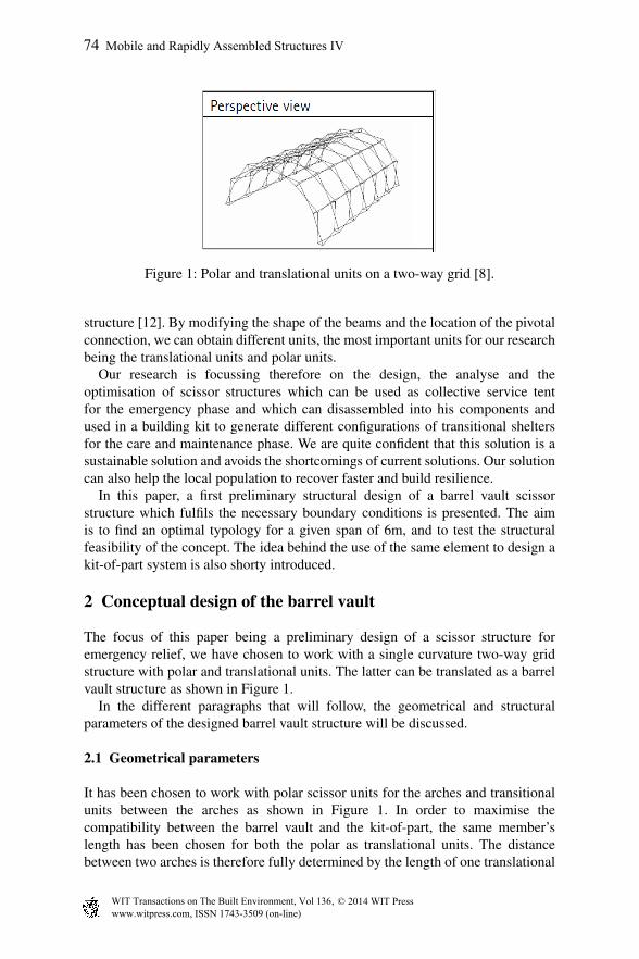
Figure 1: Polar and translational units on a two-way grid [8].
structure [12]. By modifying the shape of the beams and the location of the pivotalconnection, we can obtain different units, the most important units for our researchbeing the translational units and polar units.
Our research is focussing therefore on the design, the analyse and theoptimisation of scissor structures which can be used as collective service tentfor the emergency phase and which can disassembled into his components andused in a building kit to generate different configurations of transitional sheltersfor the care and maintenance phase. We are quite confident that this solution is asustainable solution and avoids the shortcomings of current solutions. Our solutioncan also help the local population to recover faster and build resilience.
In this paper, a first preliminary structural design of a barrel vault scissorstructure which fulfils the necessary boundary conditions is presented. The aimis to find an optimal typology for a given span of 6m, and to test the structuralfeasibility of the concept. The idea behind the use of the same element to design akit-of-part system is also shorty introduced.
2 Conceptual design of the barrel vault
The focus of this paper being a preliminary design of a scissor structure foremergency relief, we have chosen to work with a single curvature two-way gridstructure with polar and translational units. The latter can be translated as a barrelvault structure as shown in Figure 1.
In the different paragraphs that will follow, the geometrical and structuralparameters of the designed barrel vault structure will be discussed.
2.1 Geometrical parameters
It has been chosen to work with polar scissor units for the arches and transitionalunits between the arches as shown in Figure 1. In order to maximise thecompatibility between the barrel vault and the kit-of-part, the same member’slength has been chosen for both the polar as translational units. The distancebetween two arches is therefore fully determined by the length of one translational
74 Mobile and Rapidly Assembled Structures IV
www.witpress.com, ISSN 1743-3509 (on-line) WIT Transactions on The Built Environment, Vol 136, © 2 014 WIT Press

units and the deployability constraint a + b = c + d which states that in order astructure to be deployable, the sum of the semi-lengths a and b of a scissor unit hasto equal the sum of the semi-lengths c and d of the adjoining unit [8].
After some discussions that we had with Y. Garbusinski from Medecins SansFrontieres Operation Centre Brussels Logistic department, it has been noted thatcollective service tents with an opening varying from 6 to 8 meters are reallyoptimal. In this paper, an span of 6m has therefore been chosen.
The depth of the barrel vault structure does not matter for this part of theresearch. In function of the needed depth, different modules consisting of archesand translational units in-between can be added. The preliminary design presentedin this paper is analysed using two arches and one set of translational units to linkthem.
For the cross-section of the scissor units, a box with a thickness of 2mm is used.The height h and width b of the section are determined when carrying the structuralanalysis.
The number of units has directly an impact on the length of the scissor units.The more units, the smaller the elements. Because the aim is to obtain a structurewhich can easily be disassembled , we have putted a restriction for the length ofthe elements to 2.5m. This gives us a choice between 4, 6 or 8 units (more than8 units are not optimal because of the additional weight of the structural elementsand the joints between the units).
At last, the structural thickness of the barrel vault is chosen to 45cm.
2.2 Material
The material that will be used is Aluminium 6061-TG (E = 69GPa, fy =241MPa), because of his low density in comparison to steel but still with a highstrength.
2.3 Supports
The barrel vault structure is hinged on each support with the ground, this meanson 4 points per arches. In the finite element model of this work, there are therefore8 supports (Figure 2).
2.4 Loading parameters
When determining the load cases and load combination on the barrel vault, thestructure has not been considered as a ’temporary structure’. It is indeed unclearduring humanitarian crisis how long the collective service tents are used andtherefore, it has been chosen to design them as permanent structures. However,the conceptual design of the current barrel vault structure does not take tornadoes,hurricanes or typhoons into account. For readers interested in calculation methodswhich take the later into account, we refer to [13].
Mobile and Rapidly Assembled Structures IV 75
www.witpress.com, ISSN 1743-3509 (on-line) WIT Transactions on The Built Environment, Vol 136, © 2 014 WIT Press
2.4.1 Load casesThe first considered load case is the self weight.
The calculation for the force caused by the wind is described in Eurocode 1-4:Wind actions where the barrel vault has to be divided into 3 parts A, B and C asmentioned in Figure 7.11 of the Eurocode [14]. The wind direction is towards thecentre of the barrel vault. For the wind speed, the Transitional Shelter Standardswritten by the Shelter Centre has been used [15]. The wind speed is 18m/s. Thevalues obtained for this research are: 0.48kN/m2 (for zone A), −0.62kN/m2 (forzone B), −0.26kN/m2 (for zone C).
The details for the calculation of the snow loads are available in Eurocode 1-3: Snow loads [14]. Again, for the snow loads, the Transitional Shelter Standardsmentions 0, 3kN/m2 [15].
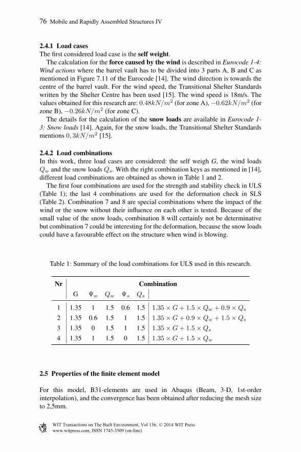
2.4.2 Load combinationsIn this work, three load cases are considered: the self weigh G, the wind loadsQw and the snow loads Qs. With the right combination keys as mentioned in [14],different load combinations are obtained as shown in Table 1 and 2.
The first four combinations are used for the strength and stability check in ULS(Table 1); the last 4 combinations are used for the deformation check in SLS(Table 2). Combination 7 and 8 are special combinations where the impact of thewind or the snow without their influence on each other is tested. Because of thesmall value of the snow loads, combination 8 will certainly not be determinativebut combination 7 could be interesting for the deformation, because the snow loadscould have a favourable effect on the structure when wind is blowing.
Table 1: Summary of the load combinations for ULS used in this research.
Nr CombinationG Ψw Qw Ψs Qs
1 1.35 1 1.5 0.6 1.5 1.35 ×G+ 1.5 ×Qw + 0.9 ×Qs
2 1.35 0.6 1.5 1 1.5 1.35 ×G+ 0.9 ×Qw + 1.5 ×Qs
3 1.35 0 1.5 1 1.5 1.35 ×G+ 1.5 ×Qs
4 1.35 1 1.5 0 1.5 1.35 ×G+ 1.5 ×Qw
2.5 Properties of the finite element model
For this model, B31-elements are used in Abaqus (Beam, 3-D, 1st-orderinterpolation), and the convergence has been obtained after reducing the mesh sizeto 2,5mm.
76 Mobile and Rapidly Assembled Structures IV
www.witpress.com, ISSN 1743-3509 (on-line) WIT Transactions on The Built Environment, Vol 136, © 2 014 WIT Press

Table 2: Summary of the load combinations for SLS used in this research.
Nr CombinationG Ψw Qw Ψs Qs
5 1 1 1 0.6 1 1 ×G+ 1 ×Qw + 0.6 ×Qs
6 1 0.6 1 1 1 1 ×G+ 0.6 ×Qw + 1 ×Qs
7 1 1 1 0 1 1 ×G+ 1 ×Qw
8 1 0 1 1 1 1 ×G+ 1 ×Qs
Figure 2: The finite element model presented in this paper for 8 units.
In order to simulate the effect of the intermediate node, the legs have beendefined as parts (one leg = one part) with a Join + Revolute (hinge) connector in-between, each time perpendicular to the part’s local axis. Because the membranehas not been modelled in this work, the wind and snow loads acting in fact on themembranes have been simulated as point forces on the different nodes (the greenarrows in Figure 2). The vertical downwards green arrows on the nodes stands forthe snow loads, the radial green arrows for the wind loads and the big green arrowfor the self weight. One can note that the radial arrows are sometimes directedtowards the inside of the barrel vault, and sometimes away from it. This is becauseof the pressure/suction effect caused by wind (in the example of Figure 2, the windis blowing from right to left and this causes pressure on the right side (zone A) andsuction on the upper and left side of the dome (zone B and C).
Mobile and Rapidly Assembled Structures IV 77
www.witpress.com, ISSN 1743-3509 (on-line) WIT Transactions on The Built Environment, Vol 136, © 2 014 WIT Press

3 Structural analysis on the barrel vault
After making a convergence analysis of the finite element model, the elements ofthe barrel vault structure have been dimensioned in function of the forces actingon the structure. Different analyses have been realised in order to calculate themaximum stress, the maximum deformation and the critical eigenvalues.
3.1 Results and discussion of the analysis
The first step is to analyse the most critical load cases for the calculation ofthe stress, the eigenvalues, and the displacement (Table 3). Then, the followingparameters are calculated in function of the span for the most critical load cases(Table 4):
• nunits,pol - Number of polar units per arches• lleg - Length of the scissor element: this is the length of one leg of the scissor
element• Ac - Optimal cross-section: this is the cross-section needed in order to fulfil
the strength criteria and local buckling (height x width).• V - Volume: this is the volume of the structural elements made of
Aluminium of the barrel vault structure• δ - Deformation: this is the maximal deformation of the structure under SLS• σmax - Maximal stress: The maximal stress in the whole structure under
ULS (must be lower than 241MPa)• λ - Eigenvalues: If this value is greater than one, global buckling doesn’t
occur (ULS).
Table 3: Comparison between the different load cases for 6 units and a cross-section of 40x25mm.
LC δ (cm) σmax (MPa) λ
1 234 -1,8072 114 -2,48573 795 3,64334 231 -1,93015 7,376 5,637 7,468 1,56
78 Mobile and Rapidly Assembled Structures IV
www.witpress.com, ISSN 1743-3509 (on-line) WIT Transactions on The Built Environment, Vol 136, © 2 014 WIT Press

Table 3 gives a good overview of the impact of the different load cases. Theresults are in fact what we expected. Because the biggest load case is the oneproduced by the wind, for the strength criteria but also for the eigenvalue, theload case with the highest safety factor on the wind will be decisive. This is loadcase 1. For the deformation, as expected too, load case 7 is decisive. The snow isfavourable for the structure when the wind is blowing. Therefore, when the snowis not considered, the biggest deformation is obtained.
Table 4: Comparison between barrel vaults with different number of units.
nunits,pol lleg (m) Ac (mm2) V (cm3) δ (cm) σmax (MPa) λ
4 2.50 55x45 12740 11 235 -2.356 1.72 40x25 8259 7 234 -1.818 1.34 45x35 10452 6 217 -5.82
Different important conclusions can be made from the performed analysis(important results shown in Table 4). As it can be seen, the optimal number ofunits is 6. One can notice that the length of the scissor units becomes smaller forincreasing number of units (for the same span of 6m) which is of course trivial.For a number of units of 4, the length of the unit is 2.5m, which is the upper limitset in the previous section.
As shown in Table 4, the number of units is not inversely proportional to theneeded area for the cross-sections of the scissor units. When going from 6 to 8units, the additional weight becomes too important and the stresses in the elementsare higher. This difference in weight is not so important when going from 4 unitsto 6 units. There is therefore an optimum number of units in function of the spanand the loading conditions. In this case, this optimum is 6 units.
Figure 3 shows the distribution of the stress in the finite element model for thesame wind distribution as Figure 2. In this same figure, the maximum deformationof 7cm is shown. This figure gives a good idea of the deformation that the structurewill have to endure under load case 7 for 6 units.
4 A short introduction to the concept of kit-of-parts structures
In this section, only the concept behind the idea will be explained.Taking into consideration the barrel vault structure with 6 units, one can note
that the same leg is always used. The leg is 1.72m long and has a cross-sectionof (40x25)mm2. The aim now is to disassemble the barrel vault structure and touse the cross-section to design truss sheds. The truss shed must therefore havemembers who are multiples of 1.72. In the sketch shown in Figure 4, an example
Mobile and Rapidly Assembled Structures IV 79
www.witpress.com, ISSN 1743-3509 (on-line) WIT Transactions on The Built Environment, Vol 136, © 2 014 WIT Press

Figure 3: The stress distribution and the displacement vector of the barrel vaultstructure with 6 units under load case 1 (for stress) and 7 (fordisplacement).
Figure 4: An example of the process from deployable shelter to transitional shelter.
of the process is given. After a structural analysis on those structures, we couldgive an overview of the needed elements for different kind of shelters.
Because the structural element of the scissor structure needs to be used fordifferent purposes, they have to allow adaptability. Therefore, the proposition isto procure, before the construction of the barrel vault, in each element, differentholes for bolts as shown in Figure 4. By opting for this, the same structural elementcan be used for different purposes.
80 Mobile and Rapidly Assembled Structures IV
www.witpress.com, ISSN 1743-3509 (on-line) WIT Transactions on The Built Environment, Vol 136, © 2 014 WIT Press
5 Conclusion and further work
Because of the lack of compatibility between the collective service tents used forthe emergency phase and the transitional shelters for the care and maintenancephase, our research is focussing on the design, the analyse and the optimisation ofscissor structures which can be used as collective service tent for the emergencyphase and which can disassembled into his components and used in a buildingkit to generate different configuration of transitional shelters for the care andmaintenance phase.
A first preliminary study has been presented in this paper where the structuralfeasibility of the concept is tested (the focus laid on the barrel vault structure).It has been seen that 6 is the optimal number of units per arches for theboundary conditions of this work and a span of 6m. The optimal cross-sectionis (40x25)mm2. Furthermore, the pressure and suction effect of the wind had agreat important on the deformation of the structure.
At last, a very brief introduction has been formulated to make the link betweenthe scissor arches and the kit-of-part structure.
The results of this paper are very promising because it shows the structuralfeasibility of the concept. Our research will now focus on a better optimisationof the structure, not only to the weight, but also to the compactness. In orderto optimise those structures, multi-criteria optimisation algorithms will be used.Furthermore, the kit-of-part solutions will be elaborated, a structural analysis willbe realised for the different concepts and finally, the building kit will be designed.
References
[1] Guha-Sapir, D., Hoyois, P. & Below, R., Annual Disaster Statistical Review2012: The Numbers and Rends. CRED: Brussels, 2013.
[2] Office of the United Nations High Commissioner for Refugees, Displace-ment, The New 21st Century Challenge. Global Trends 2012. United NationsHigh Commissioner for Refugees: Geneva, Switzerland, 2013.
[3] Corsellis, T. & Vitale, A., Transitional settlement displaced population.Oxfam GB: Oxford, 2005.
[4] International Federation of Red Cross and Red Crescent Societies,Emergency items catalogue, 2014.
[5] Centre, S., Transitional shelter guidelines. Shelter Centre, 2011.[6] Silva, J.D., Transitional shelter quality, standards and upgrading guidelines.
UNHCR, 2005.[7] Jensen, F.V., Concepts for rectrable roof structures. University of Cambridge,
2004. PhD Dissertation.[8] Temmerman, N.D., Design and Analysis of Deployable Bar Structures for
Mobile Architectural Applications. Vrije Universiteit Brussel, 2007. PhDDissertation.
[9] Pinero, E.P., Project for a Mobile Theatre – Architectural Design. Volume 12edition, 1961.
Mobile and Rapidly Assembled Structures IV 81
www.witpress.com, ISSN 1743-3509 (on-line) WIT Transactions on The Built Environment, Vol 136, © 2 014 WIT Press

[10] Gante, C., Deployable structures: Analysis and Design. WIT Press, 2001.[11] Akgu, Y., A Novel Transformation Model for Deployable Scissor-Hinge
Structures. University of Stuttgart, 2010. PhD Dissertation.[12] Alegria Mira, L., Design and Analysis of a Universal Scissor Component for
Mobile Architectural Applications. Vrije Universiteit Brussel, 2010. Masterthesis.
[13] Federal Emergency Management Agency, Design and ConstructionGuidance for Community Shelters. FEMA, first edit edition, p. 222, 2000.
[14] Eurocode 1, Eurocode 1: Actions on structures. CEN Central Secretariat,2002.
[15] Shelter Centre, Transitional Shelter Standards (draft). Shelter Centre, p. 29,2010.
82 Mobile and Rapidly Assembled Structures IV
www.witpress.com, ISSN 1743-3509 (on-line) WIT Transactions on The Built Environment, Vol 136, © 2 014 WIT Press