conditioned slicing for efficient multiway decision...
TRANSCRIPT

Journal of Computer Science, 9 (3): 314-326, 2013
ISSN 1549-3636
© 2013 S. Elmansori, This open access article is distributed under a Creative Commons Attribution
(CC-BY) 3.0 license
doi:10.3844/jcssp.2013.314.326 Published Online 9 (3) 2013 (http://www.thescipub.com/jcs.toc)
314 Science Publications
JCS
Conditioned Slicing for Efficient
Multiway Decision Graphs Model-Checker
Saad Elmansori
Department of Electrical and Computer Engineering, Concordia University,
1455 de Maisonneuve W. Montreal, Quebec, H3G 1M8, Canada
Received 2013-03-09, Revised 2013-04-12; Accepted 2013-04-23
ABSTRACT
Integrating formal verification techniques into the hardware design process provides the means to rigorously prove critical properties. However, most automatic verification techniques, such as model checking, are only effectively applicable to designs of limited sizes due to the state explosion problem. The Multiway Decision Graphs (MDG) method is an efficient method to define hardware designs into more abstract environments; however, the MDG model checker (MDG-MC) still suffers from the state explosion problem. Furthermore, all the backward reduction algorithms cannot be used in MDG, due to the presence of abstract state variables. In this study, an efficient extractor for MDG Hardware Descrpiton Languge (MDG-HDL) is introduced based on static (SS-MDG) and conditioned (CS-MDG) program slicing techniques. The techniques can obtain a chaining slice for given signals of interest. The main advantages of these techniques are: It has no MDG-HDL coding style limitation, it is accurate and it is competent in dealing with various MDG-HDL constructions. The main motivation for introducing this approach is to tackle the state explosion problem of MDG-MC that big MDG-HDL may cause. We apply our proposed techniques on different MDG-HDL designs and our analyses have shown that the proposed reduction techniques resulted in significantly improved performance of the MDG-MC. In this study, we present a general idea of program slicing, a discussion of how to slice MDG-HDL programs, implementation of the tool and a brief overview of some applications and experimental results. The underlying method and the tool based on it need to be empirically evaluated when applying to various applications.
Keywords: Multiway Decision Graphs, Model Checking, Program Slicing, MDG-HDL
1. INTRODUCTION
Nowadays, designers use Hardware Description
Languages (HDLs) ) (Samat et al., 2011) to describe
hardware designs at different levels, from high level of
abstraction to low level circuits. One of the main
advantages of using HDLs is that they can be formally
verified to ensure the correctness of the designs at the
different levels. However, as the complexity of modern
circuit designs increase, verification of these designs has
become the main bottleneck in the whole design process
(Wang et al., 2009; Perry and Foster, 2005). One of the interesting HDLs is the HDL of Multiway
Decision Graphs (MDG-HDL) (Corella et al., 1997; Xu, 1999; Xu et al., 1998; Zhou et al., 1994; Zhou and Boulerice, 1996). The method of Multiway Decision
Graphs (MDG) is efficient in representing a design with a large data-path, where the Reduced Order Binary Decision Diagram (ROBDD) (Aziz et al., 1994; Bryant, 1992) is less efficient. The MDG tool applies its own model checking (MDG-MC) to formally verify correctness of MDG-HDL designs. However, it is known that model checking (Burch et al., 1990; Clarke et al., 1992; 1996; Jhala and Majumdar, 2009) suffers from state explosion problem due to the fact that as the number of state variables in the model being tested increases, the state spaces will increase exponentially.
Therefore, there is a need to reduce the size of MDG-
HDL descriptions so that their equivalent models have fewer states. In many cases, it is not even possible to build
the state transition relation of the design and the need for
MDG-HDL reduction techniques is even more essential in these particular cases.

Saad Elmansori / Journal of Computer Science 9 (3): 314-326, 2013
315 Science Publications
JCS
The idea of the reduction technique is as follows: if the model M can be reduced to M’, then the property P can be checked on the reduced model M’ and, in this case, we may avoid the state space explosion problem. Consequently, we need to ensure that P verified on M’ will also be verified on M. In other words, we need to make sure that M|=P ⇔ M’|=P in order to proceed with the property checking on the reduced model.
Many of the most effective verification strategies are based on the idea of the extraction of useful verification knowledge from HDL description for design parts of interest. Program slicing which was originally proposed by (Weiser, 1984), is a static program analysis technique to extract appropriate fractions of sequential programs relevant to an application. These fractions are referred to as slices artifacts that preserve exact information about the program’s behavior projected onto the relevant segments of the original program. These techniques has been widely studied and applied to numerous applications in software engineering such as debugging (Deng et al., 2000), testing (Lyle and Gallagher, 1998), maintenance (Gallagher and Lyle, 1991) and reuse (Lanubile and Visaggio, 1997). The slicing technique presents an opportunity to formulate an efficient method to extract a part of a design described in an HDL.
This study describes the theoretical basis of using program slicing for dealing with the descriptions of designs in a MDG-HDL. We propose a new structure to represent the signal dependency between source code’s components of the MDG-HDL, the Components Dependence Graph (CDG). As a result, we can deal with slicing for given signals only with the relevant MDG-HDL’s components. To the best of our knowledge, this is the first try to use program slicing to extract a part from MDG-HDL descriptions. Our method makes MDG-MC more efficient in dealing with bigger designs. Also, our method can be very helpful in debugging errors in a big MDG-HDL source code.
The contributions of this study are as follows:
• We proposed and implemented static and
conditioned slicer techniques for MDG-MC, called
SS_MDG and CS-MDG
• Our approaches are fully automatic. In other words,
our approaches do not need a knowledgeable user to
be able to generate meaningful slices
• Our approaches are the first slicer techniques that
can handle the inter-model signal dependency in
MDG-based designs • We have validated our proposed technique using a
simple case study. Our results show the remarkable efficiency of using our approaches in terms of time, size and memory
The rest of this study is organized as follows. I give
the related work, a preface the basic background. Alos, I
describe the introduced Components Dependence Graph
of MDG-HDL (CDG). Then I discusse conditioned
slicing approaches for MDG-HDL. Then I describe how
to apply slicing technique for efficient MDG-MC.
Finally I show a case study with expermintal results,
conclusion and future work.
1.1. Related Work and Backgrounds
The goal of model reduction techniques is to identify
substructures of logic, which can be replaced by simpler
equivalent pieces of logic. In general, there are two
classes of reduction techniques: automatic techniques
where the reduction can be done with no manual
intervention and manual techniques which need some
degree of manual effort to be able to identify irrelevant
substructures. In the context of hardware verification, a
majority of the reduction techniques are applied at the
gate level (Boolean level) of the hardware design
description. The following is an overview of the
reduction techniques used in model checking; it is by no
means comprehensive, but summarizes the most relevant
reduction techniques.
Logic optimization techniques, including Boolean
minimization and constant propagations, are the basic
logic minimization algorithms of the reduction
techniques (Hachtel and Somenzi, 1996; De Michelli,
1994). Fan-in cone reduction is the class of reduction
techniques involved in identifying the set of
environment/model signals that are essential for the
specification being checked and in neglecting all
others. The reduction of the independent state
machines and unreachable states is another category
of the automatic reduction techniques (FSM
minimization) (Aziz et al., 1994). Another class of
reduction techniques such as symmetry reduction,
abstraction and compositional verification can
significantly reduce state space. However, none of
these methods are fully automated; therefore, they
need some manual or full manual effort, or require the
model to be expressed in an intermediate format. Verification approaches are mainly based on the
extraction of useful verification information from HDLs for design component of attention. Various researches give a lot of attention to extraction controller from datapath (Moundanos et al., 1998; Ho et al., 1995) and verifying the controller part only. Though, the introduced techniques are not capable to deal with big designs efficiently because the ability of separating controller form datapath depends on assigning specific labels
Saad Elmansori / Journal of Computer Science 9 (3): 314-326, 2013
316 Science Publications
JCS
manually. This process of labeling hundreds of control registers is difficult especially in the case where the original designers are not available.
Slicing technique (Tip, 1995) is a source to source
transformation technique and it can be used to extract a
part of interest from a design described in HDL.
However, slicing algorithms are developed originally for
sequential languages. Therefore, they cannot be used
without modification for slicing HDLs which tolerate
concurrent constructs. Slicing technique has been
extended to HDLs and the technique has effectively been
applied to hardware verification. The study in (Hachtel
and Somenzi, 1996) suggested an approach to use
program slicing for analyzing VHDL designs. They used
the VHDL simulation semantic to explain the slice model
based on a new dependence graph called signal dependence
to emulate the concurrent execution of HDL, which is an
inter-process dependence. Clarke et al. (1999) proposed an
automated slicing technique for VHDL. They introduced
System Dependence Graphs (SDG) and presented a
mapping from VHDL to generic graph-reachability
representation. In the work (Vasudevan et al., 2006), which
is the work most related to ours, the authors proposed a
reduction technique that extends the conditioned slicing
technique to HDLs’ They have developed a technique for
computing conditioned slicing to HDLs from the
antecedent of property specifications.
In view of the fact that there is no pre-image
operation in MDG due to the presence of abstract
variables, none of the backward reduction algorithms are
appropriate for MDG Consequently, it is desirable to
apply the reduction techniques at a higher level of
abstraction. There has been considerable work conducted
over the years on developing model reduction techniques
for the MDG-MC in order to solve the state space
explosion problem (Abed et al., 2007; Al-Sammane et al.,
2007; Hou and Cerny, 2000). The work in (Hou and
Cerny, 2000) introduces a model reduction technique
based on property dependent state variables of a property
P that needs to be verified. The authors proposed a
technique based on a heuristic iterative reduction
algorithm. Moreover, the authors of (Al-Sammane et al.,
2007) proposed another idea to construct a reduced
MDG model for a circuit described in a more abstract
level. By using a high level symbolic simulation and
by running appropriate symbolic simulation patterns,
the reduced model can be obtained from a circuit
described in VHDL. Also, in (Abed et al., 2007), they
used a rewriting based SAT solver to prune the
transition relation Tr of the circuits in order to
produce a smaller one that is fed to the MDG-MC.
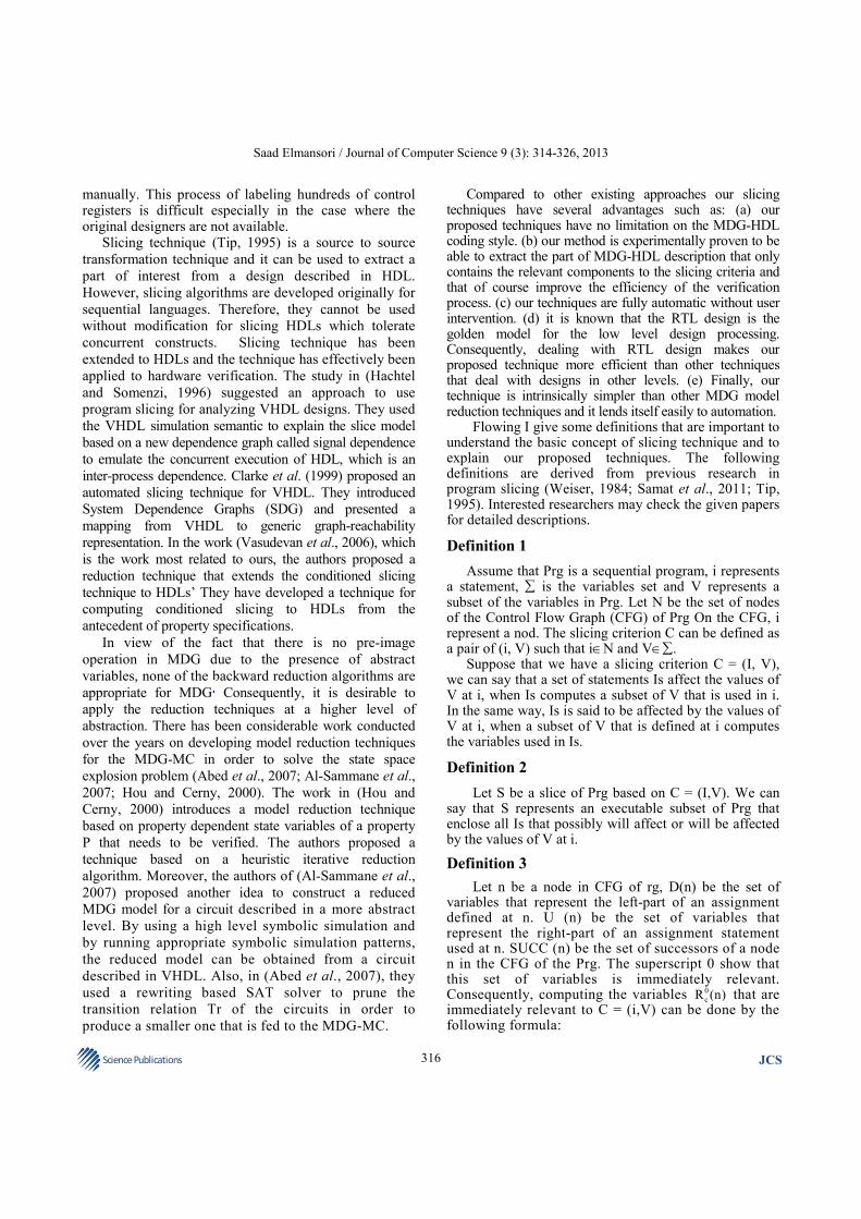
Compared to other existing approaches our slicing techniques have several advantages such as: (a) our proposed techniques have no limitation on the MDG-HDL coding style. (b) our method is experimentally proven to be able to extract the part of MDG-HDL description that only contains the relevant components to the slicing criteria and that of course improve the efficiency of the verification process. (c) our techniques are fully automatic without user intervention. (d) it is known that the RTL design is the golden model for the low level design processing. Consequently, dealing with RTL design makes our proposed technique more efficient than other techniques that deal with designs in other levels. (e) Finally, our technique is intrinsically simpler than other MDG model reduction techniques and it lends itself easily to automation.
Flowing I give some definitions that are important to understand the basic concept of slicing technique and to explain our proposed techniques. The following definitions are derived from previous research in program slicing (Weiser, 1984; Samat et al., 2011; Tip, 1995). Interested researchers may check the given papers for detailed descriptions.
Definition 1
Assume that Prg is a sequential program, i represents a statement, ∑ is the variables set and V represents a subset of the variables in Prg. Let N be the set of nodes of the Control Flow Graph (CFG) of Prg On the CFG, i represent a nod. The slicing criterion C can be defined as a pair of (i, V) such that i∈N and V∈∑.
Suppose that we have a slicing criterion C = (I, V), we can say that a set of statements Is affect the values of V at i, when Is computes a subset of V that is used in i. In the same way, Is is said to be affected by the values of V at i, when a subset of V that is defined at i computes the variables used in Is.
Definition 2
Let S be a slice of Prg based on C = (I,V). We can say that S represents an executable subset of Prg that enclose all Is that possibly will affect or will be affected by the values of V at i.
Definition 3
Let n be a node in CFG of rg, D(n) be the set of variables that represent the left-part of an assignment defined at n. U (n) be the set of variables that represent the right-part of an assignment statement used at n. SUCC (n) be the set of successors of a node n in the CFG of the Prg. The superscript 0 show that this set of variables is immediately relevant. Consequently, computing the variables 0
cR (n) that are immediately relevant to C = (i,V) can be done by the following formula:
Saad Elmansori / Journal of Computer Science 9 (3): 314-326, 2013
317 Science Publications
JCS
0 0
c c
0
c
R (n) {v V | n i} {U(n) | D(n) R
(SUCC(n) }) {R (SUCC(n)) D(n))}
= ∈ = ∪ ∩
≠ φ ∪ −
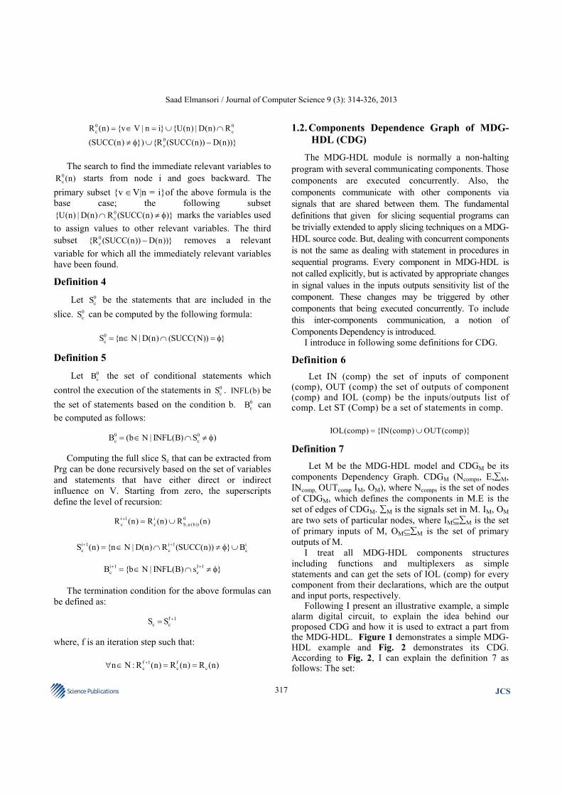
The search to find the immediate relevant variables to 0
cR (n) starts from node i and goes backward. The
primary subset {v ∈V|n = i}of the above formula is the
base case; the following subset 0
c{U(n) | D(n) R (SUCC(n) )}∩ ≠ φ marks the variables used
to assign values to other relevant variables. The third
subset 0
c{R (SUCC(n)) D(n))}− removes a relevant
variable for which all the immediately relevant variables
have been found.
Definition 4
Let 0
cS be the statements that are included in the
slice. 0
cS can be computed by the following formula:
0
cS {n N | D(n) (SUCC(N)) }= ∈ ∩ = φ
Definition 5
Let 0
cB the set of conditional statements which
control the execution of the statements in 0
cS . INFL(b) be
the set of statements based on the condition b. 0
cB can
be computed as follows:
0 0
c cB (b N | INFL(B) S )= ∈ ∩ ≠ φ
Computing the full slice Sc that can be extracted from
Prg can be done recursively based on the set of variables
and statements that have either direct or indirect
influence on V. Starting from zero, the superscripts
define the level of recursion:
i 1 i 0
c c b,u (b))R (n) R (n) R (n)+ = ∪
i 1 i 1 i
c c cS (n) {n N | D(n) R (SUCC(n)) } B+ += ∈ ∩ ≠ φ ∪
i 1 I 1
c cB {b N | INFL(B) s }+ += ∈ ∩ ≠ φ
The termination condition for the above formulas can
be defined as:
f 1
c cS S +=
where, f is an iteration step such that:
f 1 f
c c cn N : R (n) R (n) R (n)+∀ ∈ = =
1.2. Components Dependence Graph of MDG-
HDL (CDG)
The MDG-HDL module is normally a non-halting
program with several communicating components. Those
components are executed concurrently. Also, the
components communicate with other components via
signals that are shared between them. The fundamental
definitions that given for slicing sequential programs can
be trivially extended to apply slicing techniques on a MDG-
HDL source code. But, dealing with concurrent components
is not the same as dealing with statement in procedures in
sequential programs. Every component in MDG-HDL is
not called explicitly, but is activated by appropriate changes
in signal values in the inputs outputs sensitivity list of the
component. These changes may be triggered by other
components that being executed concurrently. To include
this inter-components communication, a notion of
Components Dependency is introduced.
I introduce in following some definitions for CDG.
Definition 6
Let IN (comp) the set of inputs of component (comp), OUT (comp) the set of outputs of component (comp) and IOL (comp) be the inputs/outputs list of comp. Let ST (Comp) be a set of statements in comp.
IOL(comp) {IN(comp) OUT(comp)}= ∪
Definition 7
Let M be the MDG-HDL model and CDGM be its
components Dependency Graph. CDGM (Ncomps, E,∑M,
INcomp, OUTcomp IM, OM), where Ncomps is the set of nodes
of CDGM, which defines the components in M.E is the
set of edges of CDGM. ∑M is the signals set in M. IM, OM
are two sets of particular nodes, where IM⊆∑M is the set
of primary inputs of M, OM⊆∑M is the set of primary
outputs of M.
I treat all MDG-HDL components structures
including functions and multiplexers as simple statements and can get the sets of IOL (comp) for every component from their declarations, which are the output and input ports, respectively.
Following I present an illustrative example, a simple alarm digital circuit, to explain the idea behind our proposed CDG and how it is used to extract a part from the MDG-HDL. Figure 1 demonstrates a simple MDG-HDL example and Fig. 2 demonstrates its CDG. According to Fig. 2, I can explain the definition 7 as follows: The set:

Saad Elmansori / Journal of Computer Science 9 (3): 314-326, 2013
318 Science Publications
JCS
Fig. 1. MDG-HDL source code

Saad Elmansori / Journal of Computer Science 9 (3): 314-326, 2013
319 Science Publications
JCS
Fig. 2. CDG of theMDG-HDL in Fig. 1
compsN {(A _ B),(G _ B),(G _ E),
(G _ G),(G _ F),(G _ C),(G _ D)}
=
And the data in the set E are edges; for instance
{{A_B}→(G_E),{(G_B) →(G_E)} {(G_B) →(G_E)} and so forth:
• ∑M = {(window 1), (window 2), (window 5)
• (window 6), (door 1), (door 2), (A_out), (B_out)
• (C_out), (D_out), (E_out), (F_out), (Gout)}
• INcomp= {(G_A)→{window 1, window 2}
• OUTcomp = {(G_A)→ {(A_out)}
• IM = {(window 1), (window 2), (window 5)
• (window 6), (door 1), (door 2)}
• OM = {Gout}
1.3. Conditioned Slicing Approaches for MDG-
HDL
Based on the introduced detentions, we can conclude
that CDGM can be applied in same way with minor
modifications to slice MDG-HDL.
Definition 8
Let CFGcomps be a set of control flow graphs of MDG-HDL components CFGcomp⊆CFGcomps. Let C = (VTC, STO, IM) is a slicing criteria where, VTc is the assign constant variables that will use as a condition for slcing in every CFGcomp, STO is the slicing target output. VTC ⊆ IM and STO ⊆ OM.
A chaining slice on a chaining slicing criterion C =
(VTC, STO, IM), represented by ChS, is an executable
subset of M including all the component statements
which contribute either directly or indirectly to the value
of ∑M starting from the STO. In order to apply slicing
on the MDG-HDL which has concurrent structures, we
need to extend the original Weiser algorithm based on
CDGM and CFGcomps. Our proposed method consists of
three main computing steps: (1) Transforming the slicing
criteria to conventional slicing criteria. (2) Apply slicing
on CDGM to find all relevant components and mark each
reached component as Relevant Components (RC). RC
⊆RCS, where RCS is Relevant Components Set. (3) The
last step is to slice in the set of extracted components
statements using CFGcomps.

Saad Elmansori / Journal of Computer Science 9 (3): 314-326, 2013
320 Science Publications
JCS
Fig. 3. Reduced CDG of the MDG-HDL for output (A_out)
Fig. 4. MDG-HDL source code
Following I am going to discuss the three steps of
our proposed technique. I make one realistic assumption
on the MDG-HDL as follows: All the variables defined
in MDG-HDL have to be declared as inputs and
outputs. This assumption makes it easy to handle all
MDG-HDL’s components as simple sequential
statements. Also, it ensures that our technique will not
lose generality.
1.4. Slicing the CDGM and CFGcomps
The slicing criterion that we use in our proposed
technique differs from the usual sequential slicing
criterion. Our proposed slicing criterion does not include
the statements where the criterion variables are defined
and where the backward slicing started. Consequently,
we have to transform our criterion into conventional
form. To do so, we need first to specify STO and then
search through the CDGM to find the set of components
nodes and mark it as relevant RCS, where RCS =
{comp|comp∈Ncomps) AND STO∈∑M}. Once all the
RCS are found, we need to deal with every comp
included in RCS individually based on its CFGcomp and
search in its If-Then-Else statements. We slice away the
statement where the condition value of VTC is not true.
As a result of the slicing process, all the signals between
components, the number components including flip flops
will be reduced.
The method used to find comps based on CFGcomps is
a breadth first searching algorithm. It first marks all the
nodes which have out edges pointing to the criterion
component node comp. The set of nodes found in this
step is represented by Precomp. Then, for every comp in
Precomp, repeat the same process. The termination
conditions are: (a) when reach primary inputs. (b) When
reach previous reached component. (c) When reach
conditioned signals. Figure 3 and 4 show the result after
applying the slicing process on the abovemetnioed example.
1.5. Slicing for Efficient MDG-MC (CS-MDG)
Even though MDG-HDL slicing approaches have
different application such debugging and fixing big
MDG-HDL source code, our main aim to proposed this
approaches is to tackle the state space explosion problem
of MDG-MC that big MDG-HDL may cause. Therefore,
following we are going to explain how to utilize these
approaches to address the state explosion problem.
Basically, in MDG-MC, digital designs under
verification are modeled by Abstract descriptions of
State Machines (ASMs), where both sets of states and
relations are encoded by MDGs. The specification

Saad Elmansori / Journal of Computer Science 9 (3): 314-326, 2013
321 Science Publications
JCS
language called LMDG is used to express the properties to be
verified in the MDG-MC. The approach to model checking
is to build automatically additional ASMs that represent the
property to be verified, connect the two ASMs to construct
one ASM and then check a simpler property (flag) on the
composite machine. I am not going to go in detail in this
issue since it has been explained in detail in pervious MDG
research papers. What I want to emphasize that this
composite circuit is simply an MDG-HDL code and we can
apply our proposed approaches on it with minor
modification on the slicing criteria such that:
antce MC (V ,flag, I )=
Figure 5 shows the structure of the MDG-MC, which
includes the following modules:
• MDG based model (MDG-HDL)
• Desired property which is the specification being
checked (In the LMDG specification language).( the
form of property A((Next_let_formula) U
(Next_let_formula) is not consider in our proposed
technique)
• Apl_parser (which takes the input files, the MDG
based model and the desired property, to construct a
composite circuit. This is done as follows
• The property P is transferred into a simplified
property (circuit). For example, the property
AG(apl_formula) is transferred into a simplified
property AG (flag = 1)
• The simplified property (circuit) is plugged with the
original model M. This is what we call a composite
circuit
• Property checking step is to verifies the property
validation and return (fail/pass) as a result
1.6. Illustrative Example
Figure 6 shows an example of a composite circuit.
The highlighted part of the circuit is the part that
represents ASM of the property:
( )
( )
AG(LET(v reg2)IN x 0 & ®1 0
X(reg2 finc(v)) )
= == == →
==
While the other part is the part that represents the
circuit needs be verified (the model M). So, it clear that
dealing with the code describing this circuit is just
basically dealing with normal MDG-HDL. We need only
to consider that the slicing target output is defined as
(flag) and the VTC is defined as Vantce in this case. Figure
7 demonstrate the CFGCM of the composite circuit, where
CM means composite model. Figure 8 shows the
reduced CDGCM.
1.7. MDG-HDL Slicing Algorithm
Basically, the MDG-HDL algorithm obtains the
MDG-HDL source code and the slicing criteria as inputs,
then iterates over all the criterion variables to compute
the slice. The concluding slice for the criterion is the
union of all the slices for the criterion variables. As
we mentioned before, the termination condition is
when slicing in CDGM reached all the relevant
components. Figure 9 shows the schematic diagram
of our proposed techniques. Figure 10 shows our
MDG-HDL slicing algorithm.
1.8. A Case Study
Now we are going to use the same example in Fig. 6
with some modifications such as defining the entire
signal in the circuit in Boolean level. The reason for that
is to compare our work with previous work in (Hou and
Cerny, 2000).
Fig. 5. MDG-MC

Saad Elmansori / Journal of Computer Science 9 (3): 314-326, 2013
322 Science Publications
JCS
Fig. 6. Illustrative example
Fig. 7. CDGCM of circuit in Fig. 5

Saad Elmansori / Journal of Computer Science 9 (3): 314-326, 2013
323 Science Publications
JCS
Fig. 8. Reduced CDGCM of circuit in Fig. 6
Fig. 9. Schematic diagram of slicing techniques
Saad Elmansori / Journal of Computer Science 9 (3): 314-326, 2013
324 Science Publications
JCS
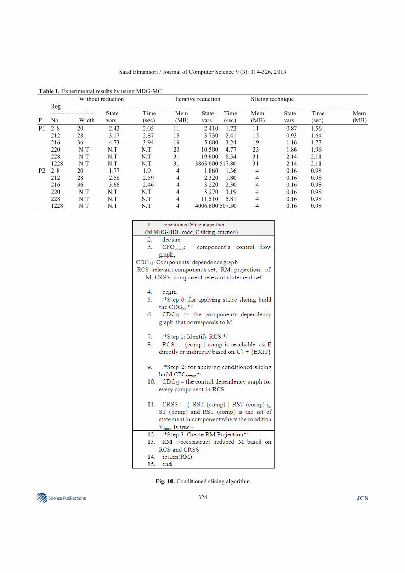
Table 1. Experimental results by using MDG-MC
Without reduction Iterative reduction Slicing technique
Reg ----------------------------------------- -------------------------------- ----------------------------------------
--------------------- State Time Mem State Time Mem State Time Mem
P No Width vars (sec) (MB) vars (sec) (MB) vars (sec) (MB)
P1 2 8 20 2.42 2.05 11 2.410 1.72 11 0.87 1.56
212 28 3.17 2.87 15 3.730 2.41 15 0.93 1.64
216 36 4.73 3.94 19 5.600 3.24 19 1.16 1.73
220 N.T N.T N.T 23 10.500 4.77 23 1.86 1.96
228 N.T N.T N.T 31 19.600 8.54 31 2.14 2.11
1228 N.T N.T N.T 31 3863.600 517.80 31 2.14 2.11
P2 2 8 20 1.77 1.9 4 1.860 1.36 4 0.16 0.98
212 28 2.58 2.59 4 2.320 1.80 4 0.16 0.98
216 36 3.66 2.46 4 3.220 2.30 4 0.16 0.98
220 N.T N.T N.T 4 5.270 3.19 4 0.16 0.98
228 N.T N.T N.T 4 11.510 5.81 4 0.16 0.98
1228 N.T N.T N.T 4 4006.600 507.30 4 0.16 0.98
Fig. 10. Conditioned slicing algorithm

Saad Elmansori / Journal of Computer Science 9 (3): 314-326, 2013
325 Science Publications
JCS
The structure of the circuit is somewhat familiar in
data processing circuits. The suitable context (such as set
of memory data, registers) is selected based on the
control signals, then dealing out with the selected context
and modified context is stored in the same memory
element. This circuit is also used somewhat in
telecommunication circuits in which channel or link
number select the matching registers to be updated. The
structure of this circuit can be simply extended and
modified to build larger circuit by adding more registers
and increasing the size of the registers.
In our care, we have defined all the signals in the
circuit in Boolean level. The registers are represented as
number of bits and every bit is treated as one Boolean
signal. The properties to be verified are as follows:
• P1: if x = 0, Reg1= 0 and the value of Reg2 = 0 in th
current clock cycle, then the value of Reg2 will be 1
in the next clock cycle
• P2: if x = 0, Reg1 = 0 and the value of Reg2[0] = 0
in th current clock cycle, then the value of Reg2[0] =
0 will be 1 in the next clock cycle
The two properties were verified on the model with
different register numbers and registers sizes. We
compare our result with previous research work results.
Table 1 illustrates our experimental results by using
MDG-MC. Base on the results we can conclude that our
proposed technique has considerably improve the
efficiency of MDG-MC. The (N.T) in the table stand for
Not Terminate.
2. CONCLUSION
To alleviate the state explosion problem in the MDG
model checking tool, we have proposed a reduction
techniques called SS_MDG and CS-MDG. The goal of
our technique is to construct a reduced MDG-HDL
source code using the Composite Circuit Dependency
Graph (CDGM) and CFGcomps.
Our technique consists of two phases: In the first
phase of the reduction based on Static Slicing (SS-MDG),
our technique extracts the relevant components that affect
the flag using the CDGM. Then, in the second phase, the
reduction that is based on the Conditioned Slicing (CS-
MDG) is applied using the information in the property
antecedent and CFGcompsCFGcomps to reduce the
components’ statements and eliminate the irrelevant
statements where the condition Vantce is not true.
We have presented the essential foundation of how to use slicing techniques to extract a part of MDG-HDL. The technique was successfully implemented as a prototype tool and effectively used for improving verification of design in MDG-HDL.
Our analyses have shown that the proposed reduction technique resulted in significantly improved the performance of the MDG model checker.
In the future, we aim to apply our technique to more
complex hardware designs in order to identify its
strengths and limits.
3. ACKNOWLEDGEMENT
I would like to thank Libyan ministry of higher
education and aide financiere aux etudes Quebec for
their support.
4. REFERENCES
Abed, S., O.A. Mohamed, Z. Yang and G. Al-Sammane,
2007. Integrating SAT with multiway decision
graphs for efficient model checking. Proceedings of
the Internatonal Conference on Microelectronics,
Dec. 29-31, IEEE Xplore Press, Cairo, pp: 129-132.
DOI: 10.1109/ICM.2007.4497677
Al-Sammane, G., S. Abed and O.A. Mohamed, 2007.
High level reduction technique for multiway
decision graphs based model checking. Proceedings
of the First International Conference on Verification
and Evaluation of Computer and Communication
Systems, (ECCS’ 07), British Computer Society
Swinton, UK., pp: 80-93.
Aziz, A., V. Singhal, G.M. Swamy and R.K. Brayton,
1994. Minimizing interacting finite state machines:
A compositional approach to language containment.
Proceedings of the IEEE International Conference
on Computer Design: VLSI in Computers and
Processors, Oct. 10-12, IEEE Xplore Press,
Cambridge, MA., pp: 255-261. DOI:
10.1109/ICCD.1994.331900
Bryant, R., 1992. Symbolic Boolean manipulation with
ordered binary-decision diagrams. ACM Comput.
Syst., 24: 293-318. DOI: 10.1145/136035.136043
Burch, J., E. Clarke and D. Long, 1990. Symbolic model
checking with partitioned transition relations.
Proceedings of the IFIP TC10/WG 10.5
International Conference on Very Large Scale
Integration, Aug. 20-22, Edinburgh, Scotland, IFIP
Transactions A-1 North-Holland.

Saad Elmansori / Journal of Computer Science 9 (3): 314-326, 2013
326 Science Publications
JCS
Clarke, E., O. Grumberg and D.L. Peled, 1992. Model checking and abstraction. Proceedings of the Nineteenth Annual ACM Symposium on Principles of Programming Languages, Jan. 19-22, ACM New York, NY, USA., pp: 343-354. DOI: 10.1145/143165.143235
Clarke, E., O. Grumberg and D.L. Peled, 1996. Model checking. Cambridge University Press.
Clarke, E.M., Fujita and M. P.S. Rajan, 1999. Program slicing of hardware description languages. Proceedings of the Conference Correct Hardware Design and Verification Methods, (CHARME’ 99), Springer-Verlag London, UK., pp: 298-312.
Corella, F., Z. Zhou, X. Song, M. Langevin and E. Cerny, 1997. Multiway decision graphs for automated hardware verification. Formal Methods Syst. Design, 10: 7-46. DOI: 10.1023/A:1008663530211
De Michelli, G., 1994. Synthesis and Optimization of
Digital Circuits. 1st Edn., McGraw-Hill, New York,
ISBN-10: 0070163332, pp: 579.
Deng, Y., S. Kothari and Y. Namara, 2000. Program
slice browser. Proceedings of the 9th International
Workshop on Program Comprehension, May 12-13,
IEEE Xplore Press, Toronto Ont., pp: 50-59. DOI:
10.1109/WPC.2001.921713
Gallagher, K.B. and J.R. Lyle, 1991. Using program
slicing in software maintenance. IEEE Trans.
Software Eng., 17: 751-761. DOI: 10.1109/32.83912
Hachtel, G. and F. Somenzi, 1996. Logic Synthesis and
Verification Algorithems. 1st Edn., Kluwer
Academic Publishers, Boston, ISBN-10:
0792397460, pp: 600.
Ho, R., C. Yang, M. Horowitz and D. Dill, 1995.
Architecture validation for processors. Proceedings
of the Annual International Symposium on
Computer Architecture, Jun. 22-24, ACM Press,
New York, USA., pp: 404-413. DOI:
10.1145/223982.224450
Hou, J. and E. Cerny, 2000. Model reductions in MDG-
based model checking. Proceedings of the 13th
Annual IEEE International ASIC/SOC Conference,
Sept. 13-16, IEEE Xplore Press, Arlington, VA., pp:
347-351. DOI: 10.1109/ASIC.2000.880762
Jhala, R. and R. Majumdar, 2009. Software model
checking. ACM Comput. Surv. DOI:
10.1145/1592434.1592438
Lanubile, F. and G. Visaggio, 1997. Extracting reusable
functions by flow graph based program slicing.
IEEE Trans. Software Eng., 23: 246-259. DOI:
10.1109/32.588543
Lyle, J.R. and K.B.A. Gallagher, 1998. Program decomposition scheme with applications to software modification and testing. Proceedings of the Software Track, Proceedings of the Twenty-Second Annual Hawaii International Conference on System Sciences, Jan. 3-6, IEEE Xplore Press, Kailua-Kona, HI., pp: 479-485. DOI: 10.1109/HICSS.1989.48029
Moundanos, D., J.A. Abraham and Y.V. Hoskote, 1998. Abstraction techniques for validation coverage analysis and test generation. IEEE Trans. Comput., 47: 2-13. DOI: 10.1109/12.656068
Perry, DL. and H. Foster, 2005. Applied Formal Verification. 1st Edn., McGraw-Hill, New York, ISBN-10: 9780071588898, pp: 240.
Samat, P.A., A.M. Zin and Z. Shukur, 2011. Analysis of the model checkers’ input languages for modeling traffic light systems. J. Comput. Sci., 7: 225-233. DOI: 10.3844/jcssp.2011.225.233
Tip, F., 1995. A survey of program slicing techniques. J. Progr. Language, 3: 121-189.
Vasudevan, S., E. Emerson and J. Abraham, 2006. Improved verification of hardware designs through antecedent conditioned slicing. Int. J. Software Tools Technol. Transfer, 9: 89-101. DOI: 10.1007/s10009-006-0022-x
Wang, J., J. Shao, Y. Li and J. Ding, 2009. Survey on formal verification methods for digital IC. Proceedings of the 4th International Conference on Internet Computing for Science and Engineering, Dec. 21-22, IEEE Xplore Press, Harbin, 2009 pp: 164-168. DOI: 10.1109/ICICSE.2009.46
Weiser, M., 1984. Program slicing. IEEE Trans. Software Eng., 10: 352-357. DOI: 10.1109/TSE.1984.5010248
Xu, Y., 1999. Model checking for a first-order temporal logic using multiway decision graphs. Ph.D. Thesis, University of Montreal.
Xu, Y., C. Eduard, S. Xiaoyu, C. Francisco and A.M. Otmane, 1998. Model checking for a first-order temporal logic using multiway decision graphs. Comput. Aided Verificat., 1427: 219-231. DOI: 10.1007/BFb0028747
Zhou, Z. and N. Boulerice, 1996. MDGs Tools (V1.0) User’s Manual. University of Montreal.
Zhou, Z., X. Song, F. Corella, E. Cerny and M. Langevin, 1994. Description and verification of RTL designs using multiway decision graphs. Proceedings of the IFIP International Conference on Hardware Description Languages. IFIP International Conference on Very Large Scal Design Automation Conference, Aug. 29-Sep. 1, IEEE Xplore Press, Chiba, pp: 575-580. DOI: 10.1109/ASPDAC.1995.486372