constant switching frequency self-oscillating...
TRANSCRIPT

General rights Copyright and moral rights for the publications made accessible in the public portal are retained by the authors and/or other copyright owners and it is a condition of accessing publications that users recognise and abide by the legal requirements associated with these rights.
• Users may download and print one copy of any publication from the public portal for the purpose of private study or research. • You may not further distribute the material or use it for any profit-making activity or commercial gain • You may freely distribute the URL identifying the publication in the public portal
If you believe that this document breaches copyright please contact us providing details, and we will remove access to the work immediately and investigate your claim.
Downloaded from orbit.dtu.dk on: May 22, 2018
Constant Switching Frequency Self-Oscillating Controlled Class-D Amplifiers
Nguyen-Duy, Khiem; Knott, Arnold; Andersen, Michael A. E.
Published in:Elektronika ir Elektrotechnika
Link to article, DOI:10.5755/j01.eee.20.6.7273
Publication date:2014
Document VersionPublisher's PDF, also known as Version of record
Link back to DTU Orbit
Citation (APA):Nguyen-Duy, K., Knott, A., & Andersen, M. A. E. (2014). Constant Switching Frequency Self-OscillatingControlled Class-D Amplifiers. Elektronika ir Elektrotechnika, 20(6), 84-88. DOI: 10.5755/j01.eee.20.6.7273

ELEKTRONIKA IR ELEKTROTECHNIKA, ISSN 1392–1215, VOL. 20, NO. 6, 2014
1Abstract—The self-oscillating control approach has beenused extensively in class-D amplifiers. It has several advantagessuch as high bandwidth and high audio performance. However,one of the primary disadvantages in a self-oscillating controlledsystem is that the switching frequency of the amplifier varieswith the ratio of the output voltage to the input rail voltage. Inother words, the switching frequency varies with the duty cycleof the output. The drop in the frequency results in lowercontrol bandwidth and higher output voltage ripple, which areundesirable. This paper proposes a new self-oscillating controlscheme that maintains a constant switching frequency over thefull range of output voltage. The frequency difference isprocessed by a compensator whose output adjusts the total loopgain of the control system. It has been proven by simulationthat a con-stant switching frequency self-oscillating converter isachieved and the proposed control circuit performssatisfactorily.
Index Terms—Power amplifiers, frequency control, voltagecontrol, power electronics.
I. INTRODUCTION
Switch mode class-D audio amplifiers have beenreplacing the audio amplifiers made from class-A, B or ABamplifiers thanks to their superior efficiency and powerdensity [1]–[5]. For the control of class-D audio amplifiers,the modulation strategy is an integral factor that determinesthe performance of the audio amplifiers. Modulationstrategies can be classified into analogue modulation anddigital modulation.
The analogue modulation usually has better performancedue to the absence of digital delay or quantization error,which are inherent in digital modulation [6]. There havebeen two basic analogue modulation methods in theliterature, namely the triangular carrier-based modulationmethod and the self-oscillating control method. The self-oscillating control method uses a comparator with eitherhysteresis [7], [8] or zero-hysteresis [9].
Recently, the self-oscillating control method has receivedgreat attention due to its advantages over the triangularcarrier based method [6]–[13]. The advantage of the self-oscillating control system is that it allows the open-loopcontrol system magnitude to cross the 0 dB point precisely
Manuscript received December 15, 2013; accepted March 7, 2014.This research was funded by Technical University of Denmark, 2800
Kgs. Lyngby, Denmark.
IK
s
fbK
21
( / ) 1LCs L R s ˆDC
pwm
V
V
Fig. 1. A basic voltage-mode hysteresis controller.
IP D
KK K s
s
fbK
21
( / ) 1LCs L R s ˆDC
pwm
V
V
Fig. 2. A global loop integrating modulator controller.
at the oscillation frequency, providing high controlbandwidth. On the other hand, the cross over frequency ofthe carrier-based modulation control system must be at least2 times lower than the switching frequency, resulting inlower bandwidth and higher output ripple.
Figure 1 introduces a basic voltage-mode, hysteresis-based, self-oscillating control system. The output filter is asecond-order LC filter. The switching node of a syn-chronous buck converter is fed back and compared with thevoltage reference, which, in the case of audio amplifiers, is areference for the audio output signal. fbK is the feedback
constant of the switching signal. The rail voltage isDCV with respect to ground for a single supply converter, or
can be from / 2DCV to / 2DCV for dual supply audioamplifiers. For consistency, a single supply voltage isassumed. In the control scheme, the integrator amplifies theerror and provides infinite gain at dc. The phase shift createdby the integrator is –90. The negative feedback of the signalprovides a phase shift of –180. The remaining phase shift isprovided by the nature of the hysteresis comparator, the timedelay of gate driver, and the propagation of the control units.Assuming there is no other time delay produced by the otherphysical elements in the control loop, the hysteresiscomparator provides –90 phase shift at the nominalswitching frequency.
Figure 2 shows another hysteresis-based, self-oscillatingcontrol system for class-D amplifiers. It feeds back theoutput voltage instead of the switching signal. This schemeis usually referred to as the Global Loop IntegratingModulator (GLIM) scheme [12]. Since the transfer function
Constant Switching Frequency Self-OscillatingControlled Class-D Amplifiers
K. Nguyen-Duy1, A. Knott1, M. A. E. Andersen1
1Department of Electrical Engineering, Technical University of Denmark,Orsteds Plads, building 349, 2800 Kgs. Lyngby, Denmark
http://dx.doi.org/10.5755/j01.eee.20.6.7273
84
ELEKTRONIKA IR ELEKTROTECHNIKA, ISSN 1392–1215, VOL. 20, NO. 6, 2014
of the out-put filter is taken into the control loop, theintegrator in Fig. 1 is replaced by a proportional-integral-derivative (PID) controller. The PID controller cancels outthe two poles created by the output filter and provides highdc gain with its integral term. The PID controller, togetherwith the output filter, can be approximately treated as anintegral, making the open loop transfer function similar tothat in Fig. 1. The advantage of this scheme compared to thebasic scheme in Fig. 1 is that the errors from both the outputvoltage and output filter are attenuated [12].
0 0.1 0.2 0.3 0.4 0.5 0.6 0.7 0.8 0.9 100.10.20.30.40.50.60.70.80.9
1
D
Freq
uenc
y (p
.u.)
Fig. 3. Frequency (nominal to the maximum frequency) versus changes ofduty cycle.
However, a major problem with the self-oscillatingcontrol system applied in class-D amplifiers is that theswitching frequency varies with the duty cycle of the outputstage. The variation is based on a parabolic curve with peakvalue at a duty cycle of 0.5. This is due to the decrease in thegain when the duty cycle is different from 0.5. Frompreviously published papers, it can be shown that theswitching frequency has the following expression [6]–[8]
(1- ),sw
swK D D
f
(1)
where is the height of the hysteresis threshold (hysteresiswindow), swK is a constant dependant on the circuit gain,and D is the duty cycle. In the case of a single supplysystem, the modulation index is defined by the proximity ofthe output signal oV , which is biased by half the rail supplyvoltage, to the closest supply rail. Thus, the modulationindex is defined as
/ 22 1 .
/ 2o DC
DC
V VM D
V
(2)
The centre duty cycle is the duty cycle that produces themaximum frequency in a self-oscillating controlled system.In this case, the centre duty cycle is D = 0.5. A plot of theswitching frequency, nominalized to the maximumfrequency, versus the change in duty cycle is shown in Fig.3. It can be seen that the frequency drops rapidly with thechange of duty cycle away from the centre duty cycle. Forexample, when the duty cycle is 0.1 or 0.9, the switchingfrequency drops 64 %, or nearly two thirds from the nominalfrequency.
This drop in the switching frequency is undesirablebecause it results in several undesired consequences. First,the drop of the switching frequency increases the output
voltage ripple. Second, the drop causes the open-loopbandwidth and loop gain to drop as well, resulting in higherdistortion and slower dynamics. As a result, it is desired thatthe switching frequency in self-oscillating controlled systemsbe fixed at the nominal frequency in order to counteract theaforementioned drawbacks.
2IK
s
fbK
21
( / ) 1LCs L R s ˆDC
pwm
V
V1IK
s
Fig. 4. The fixed frequency self-oscillating control system proposed in [6].
( )C s
fbK
Fig. 5. The fixed frequency self-oscillating control system proposed in [8]and [13].
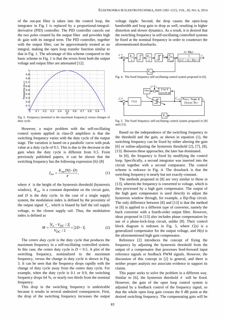
Based on the independence of the switching frequency tothe threshold and the gain, as shown in equation (1), theswitching frequency can be fixed by either altering the gain[6] or online-adjusting the hysteresis threshold [2], [7], [8],[13]. Between these approaches, the later has dominated.
In [6], the frequency is fixed by modifying the controlloop. Specifically, a second integrator was inserted into thecircuit together with a second comparator. The controlscheme is redrawn in Fig. 4. The drawback is that theswitching frequency is nearly but not exactly constant.
The methods proposed in [8] are very similar to those in[13], wherein the frequency is converted to voltage, which isthen processed by a high gain compensator. The output ofthe high gain compensator is used directly to adjust thehysteresis window through, for example, a flip-flop circuit.The only difference between [8] and [13] is that the methodin [8] is applied to a different type of converter, namely thebuck converter with a fourth-order output filter. However,ideas proposed in [13] also includes phase compensation byuse of a phase-lock-loop circuit, unlike [8]. Their controlblock diagram is redrawn in Fig. 5, where C(s) is ageneralized compensator for the output voltage, and H(s) isthe aforementioned high gain compensator.
Reference [2] introduces the concept of fixing thefrequency by adjusting the hysteresis threshold from theoutput of a compensator that processes feed-forward inputreference signals or feedback PWM signals. However, thediscussion of this concept in [2] is general, and there isneither proper analysis nor associate evidence to support itsclaims.
This paper seeks to solve the problem in a different way.Similar to [6], the hysteresis threshold will be fixed.However, the gain of the open loop control system isadjusted by a feedback control of the frequency signal, sothat the whole open loop gain crosses the 0 dB point at thedesired switching frequency. The compensating gain will be
85

ELEKTRONIKA IR ELEKTROTECHNIKA, ISSN 1392–1215, VOL. 20, NO. 6, 2014
injected to the open loop system via a multiplication unit(multiplier). The detailed description of the proposedmethod will be presented next.
II. PROPOSED CONSTANT SWITCHING FREQUENCYCONTROLLER
In the studied system, a rail voltage of 60 V dc is used tosupply the power stage. The converter is a synchronous buckconverter. The nominal load is 26 Ω. The nominal switchingfrequency is 1 MHz. The specifications of the converter tobe examined are listed in Table I.
The proposed fixed-frequency, self-oscillating controlsystem is shown in Fig. 6. The PWM signal generated by thehysteresis comparator is converted to a voltage proportionalto its frequency. This is done by passing the PWM to amono-stable multi-vibrator (MMV) or one-shot circuit witha fixed pulse width output. Each time the input to the MMVhas a rising edge, the output of the MMV generates a pulsewith a fixed width, which is 100 ns in this case. Theresulting signal of the MMV is low-pass filtered by a firstorder RC filter circuit with a cut-off frequency of 1.6 kHz.Only the dc value of the MMV remains, and it isproportional to the switching frequency. The operation ofthe MMV and the F-to-V converter are illustrated in Fig. 7and Fig. 8.
The measured switching frequency is compared to thereference switching frequency and processed by acompensator F(s). F(s) can be implemented with a PI or PIDcontroller. The output of F(s) is the compensating gain forthe self-oscillating control loop, and it is inserted to thecontrol loop through a multiplier. It adjusts the switchingfrequency of the converter to track the reference frequency,which is represented by F*.
III. SIMULATION RESULTS
The simulation studies examine different responses of theconverter using the self-oscillating control approach withoutfrequency compensation as well as with the proposedfrequency compensation. The responses are based on bothdc reference signals and sinusoidal audio reference signals.Simulation model was built in MATLAB®/Simulinkenvironment. Most parts of the controllers and feedbackwere modelled and simulated by realistic commerciallyavailable discrete components: non-ideal operationalamplifiers with limited gain-bandwidth product and limitedoutput voltage ability, etc.
A. Converter without a Frequency Compensator
Figure 9 shows the voltage transient (step) response of theconverter without a frequency compensator. The dcreference values are swept so that the duty cycle of theoutput voltage is changed. At time t = 0, the duty cycle is0.5. At times t = 70 µs, t = 140 µs, t = 210 µs, the duty cycleis 0.2, 0.1, and 0.7, respectively. The bottom of Fig. 9 showsthe switching signal generated by the comparator. It can beseen that the switching frequency varies with the change ofthe duty cycle. Its peak value is at the centre frequencywhere D = 0.5. This phenomenon can be observed moreclearly from a partial zoom of Fig. 9 which is shown in
Fig. 10.
TABLE I. THE SPECIFICATION OF THE CONVERTER.Parameter Value
L 36 µHC 100 nH
DCV 60 V
pwmV 5 V
0.66 VNominal load 26 Ω
Nominal switching frequency 1 MHztMMV 100 ns
IP D
KK K s
s
fbK
21
( / ) 1LCs L R s ˆDC
pwm
V
V
( )F s
Fig. 6. The proposed fixed frequency self-oscillating control system.
Vpwm(t)
MMV
tMMV
(a)
(b)
t
t
Fig. 7. Operation of the MMV a) the PWM output signal of thecomparator, b) the output signal of the mono-stable multi-vibrator.
11 s
Fig. 8. Frequency to voltage (F to V) converter.
Figure 11 shows response to an audio signal of theconventional converter without a frequency compensator.The frequency of the signal is 20 kHz, which represents anaudio signal for typical human hearing ability. It can beconfirmed again from the simulation result, that theswitching frequency varies with the magnitude of the audiosignal, or in other words, it varies with the switching dutycycle. As Fig. 3 suggests, the drop of the frequency at highermodulation index creates larger output ripple and distortion.This phenomenon can be observed from the top and bottomof the output voltage signal.
B. Converter with the Proposed Frequency Compensator
Figure 12 shows the step response of the self-oscillatingcontrol amplifier with the proposed frequency compensator.As can be seen, the switching frequency of the converter insteady state held constant regardless of the variation in theoutput voltage or duty cycle. The steady-state response ofthe output voltage has been improved, while a desirabletransient response is preserved. The ripple of the outputvoltage is reduced at all switching duty cycles that are
86

ELEKTRONIKA IR ELEKTROTECHNIKA, ISSN 1392–1215, VOL. 20, NO. 6, 2014
different from the centre duty cycle. This feature can be seenin the partial zoom of Fig. 12 shown in Fig. 13.
Converter without a frequency compensator is shown inFig. 9–Fig. 11.
0 50 100 150 200 2500
10
20
30
40
50
60
Time (us)
V o(V)
VoVpwm
Fig. 9. Step response of output voltage without a frequency compensator.Top: Vo (V), bottom: Vpwm (V), the duty cycle is swept from 0.5 to 0.2, 0.1,and 0.7.
50 60 70 80 90 1000
5
10
15
20
25
30
35
Time (us)
V o(V)
VoVpwm
Fig. 10. Partial zoom of the step response of output voltage without afrequency compensator. Top: Vo (V), bottom: Vpwm (V), the duty cycle isshifting from 0.5 to 0.2 at time 70 µs.
0 20 40 60 80 1000
10
20
30
40
50
60
Time (us)
Vol
tage
(V
)
VoVpwm
Transient Steady state
Fig. 11. Output response to a 20-kHz audio reference without a frequencycompensator. Top: Vo (V), bottom: Vpwm (V), the duty cycle is continuouslyvarying from 0.1 to 0.9 and vice versa.
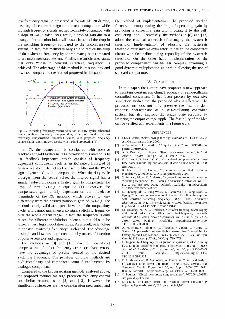
The response to an audio input signal of 20 kHz ispresented in Fig. 14. It can be seen that the switchingfrequency of the converter has been held constant even witha large variation in the duty cycle over one period. Theripple at the top peak and bottom peak of the output signal,therefore, has been significantly improved compared toFig. 11. The amplifier with the proposed constant-frequencycompensator outperforms the traditional one without afrequency compensator. Different simulations are performedwith both converters at various duty cycles. The switchingfrequencies are plotted in Fig. 15 for four cases: calculatedby equation (1), simulated model without a frequencycompensator, simulated model with the proposed frequencycompensator, and simulated model with method proposed in[6]. As can be seen, the simulated switching frequency
without a frequency compensator matches well with thecalculation. Moreover, a constant switching frequency isguaranteed with the proposed method.
0 50 100 150 200 2500
10
20
30
40
50
60
Time (us)
Vo (V
)
VoVpwm
Fig. 12. Step response of output voltage with the proposed frequencycompensator. Top: Vo (V), bottom: Vpwm (V), the duty cycle is swept from0.5 to 0.2, 0.1, and 0.7.
50 60 70 80 90 1000
5
10
15
20
25
30
35
Time (us)
V o (V)
VoVpwm
Fig. 13. Partial zoom of the step response of output voltage with theproposed frequency compensator. Top: Vo (V), bottom: Vpwm (V), the dutycycle is shifting from 0.5 to 0.2 at time 70 µs.
0 20 40 60 80 1000
10
20
30
40
50
60
Time (us)
Vol
tage
(V)
VoVpwm
Steadystate
Transient
Fig. 14. Output response to a 20-kHz audio reference with the proposedfrequency compensator. Top: Vo (V), bottom: Vpwm (V), the duty cycle iscontinuously varying from 0.1 to 0.9 and vice versa.
Converter with the proposed frequency compensator isshown in Fig. 12–Fig. 14.
IV. DISCUSSION
While most existing solutions for fixing the switchingfrequency have worked with varying the hysteresis windowwhen the duty cycle changes, the approach presented herefixes the hysteresis window and generates a compensatinggain based on the variation in frequency.
In [6], the hysteresis window is kept constant and theregulation of frequency is achieved by changing the loopgain. The added integrator is implemented by a passive RCfilter. Therefore, the low frequency gain is preserved, but thehigh frequency components are attenuated. The extracomparator differentiates the output of the added integrator,yielding clamped output signals. Therefore, the gain of the
87
ELEKTRONIKA IR ELEKTROTECHNIKA, ISSN 1392–1215, VOL. 20, NO. 6, 2014
low frequency signal is preserved at the rate of –20 dB/dec,ensuring a linear carrier signal to the main comparator, whilethe high frequency signals are approximately attenuated witha slope of –40 dB/dec. As a result, a drop of gain due to achange of modulation index will result in half of the drop inthe switching frequency compared to the uncompensatedsystem. In fact, that method is only able to reduce the dropof the switching frequency by approximately half comparedto an uncompensated system. Finally, the article also statesthat only “close to constant switching frequency” isachieved. The advantage of this method is its simplicity andlow-cost compared to the method proposed in this paper.
0 0.2 0.4 0.6 0.8 10
2
4
6
8
10x 105
D
Sw
itchi
ng fr
eque
ncy
(Hz)
uncompensated system-calculateduncompensated system-simulatedproposed method-simulatedmethod [6]-simulated
Fig. 15. Switching frequency versus variation of duty cycle: calculatedresults without frequency compensation, simulated results withoutfrequency compensation, simulated results with proposed frequencycompensation, and simulated results with method proposed in [6].
In [7], the comparator is configured with positivefeedback to yield hysteresis. The novelty of this method is touse feedback impedance, which consists of frequencydependant components such as an RC network instead ofpassive resistors. The network is used to filter out the PWMsignals generated by the comparators. When the duty cyclediverges from the centre value, the filtered signal has asmaller value, providing a higher gain to compensate thedrop of term D(1-D) in equation (1). However, thecompensated gain is only dependant on the impedancemagnitude of the RC network, which proves to varydifferently from the desired parabolic gain of D(1-D). Themethod is only valid at a specific value of the output dutycycle, and cannot guarantee a constant switching frequencyover the whole output range. In fact, the frequency is onlyraised for different modulation indexes, but it fails to beraised at very high modulation index. As a result, only “closeto constant switching frequency” is claimed. The advantageis simple and low-cost implementation by means of insertionof passive resistors and capacitors.
The methods in [8] and [13], due to their directcompensation of either frequency errors or phase errors,have the advantage of precise control of the desiredswitching frequency. The penalties of those methods arehigh complexity and component count if implemented byanalogue components.
Compared to the known existing methods analysed above,the proposed method has high precision frequency controlfor similar reasons as in [8] and [13]. However, thesignificant differences are the compensation mechanism and
the method of implementation. The proposed methodfocuses on compensating the drop of open loop gain byproviding a correcting gain and injecting it to the self-oscillating loop. Conversely, the methods in [8] and [13]adopt the classical approach of changing the hysteresisthreshold. Implementation of adjusting the hysteresisthreshold must involve extra effort to design the comparatorcircuit with fast online tuning capability of the hysteresisthreshold. On the other hand, implementation of theproposed compensator can be less complex, involving agood dynamic multiplication unit while allowing the use ofstandard comparators.
V. CONCLUSIONS
In this paper, the authors have proposed a new approachto maintain constant switching frequency of self-oscillatingcontrolled converters. It has been proven by extensivesimulation studies that the proposed idea is effective. Theproposed methods not only preserve the fast transientresponse characteristic of a self-oscillating controlledsystem, but also improve the steady state response bylowering the output voltage ripple. The feasibility of the ideacan be verified with experiments in a future work.
REFERENCES
[1] ELBO GmbH, “Selbstshwingender digitalverstärker”, DE 198 38 765A1, German patent, May 2000.
[2] A. Veltman, J. J. Hendrikus, “Amplifier circuit”, WO 00/42702, Intpatent, January 2000.
[3] A. F. Rozman, J. J. Boylan, “Band pass current control”, in Conf.Proc. IEEE (APE 1994), pp. 631–637, vol. 2, 1994.
[4] F. C. Lee, R. P. Iwens, Y. Yu, “Generalized computer-aided discretetime domain modelling and analysis of dc-dc converters”, in Conf.Rec. PESC 77.
[5] K. Nielsen, J. L. Hansen, “Synchronized controlled oscillationmodulator”, WO 03/055060 A1, Int. patent, July 2003.
[6] S. Poulsen, M. A. E. Andersen, “Hysteresis controller with constantswitching frequency”, IEEE Trans. Consumer Electronics, vol. 51,no. 2, pp. 688–693, 2005. [Online]. Available: http://dx.doi.org/10.1109/TCE.2005.1468020
[7] K. Hyoung-Sik, J. Sung-Wook, J. Hwan-Mok, S. Jang-Kyoo, C.Pyung, “Low cost implementation of filterless class-D audio amplifierwith constant switching frequency”, IEEE Trans. ConsumerElectronics, pp. 1442–1446 vol. 52, no. 4, 2006. [Online]. Available:http://dx.doi.org/10.1109/TCE.2006.273168
[8] M. Hoyerby, M. A. E. Andersen, “Ultrafast tracking power supplywith fourth-order output filter and fixed-frequency hystereticcontrol”, IEEE Trans. Power Electronics, vol. 23, no. 5, pp. 2387–2398, 2008. [Online]. Available: http://dx.doi.org/10.1109/TPEL.2008.2002038
[9] A. Huffenus, G. Pillonnet, N. Abouchi, F. Goutti, V. Rabary, C.Specq, “A phase-shift self-oscillating stereo class-D amplifier forbattery-powered applications”, in Conf. Proc. 2010 IEEE Int. Sym.Circuits & Systems (ISCAS), 2010, pp. 769–772.
[10] L. Jingxue, R. Gharpurey, “Design and analysis of a self-oscillatingclass-D audio amplifier employing a hysteretic comparator”, IEEEJournal of Solid-State Circuits, vol. 46, no. 10, pp. 2336–2349,2011. [Online]. Available: http://dx.doi.org/10.1109/JSSC.2011.2161415
[11] F. A. Malekzadeh, R. Mahmoudi, A. Roermund, “Statistical analysisof self-oscillating power amplifiers”, IEEE Trans. Circuits andSystems I: Regular Papers, vol. 58, no. 8, pp. 1865–1876, 2011.[Online]. Available: http://dx.doi.org/10.1109/TCSI.2011.2106070
[12] S. Poulsen, “Global loop integrating modulator”, WO2004100356-A2, patent application.
[13] D. Grant, “Frequency control of hysteretic power converter byadjusting hysteresis levels”, U.S. patent 6,348,780.
88