construction electrician apprenticeship program level … · learning objectives ... wye or delta....
TRANSCRIPT
CONSTRUCTION ELECTRICIAN APPRENTICESHIP PROGRAMLevel 3 Line H: Install Electrical Equipment
LEARNING GUIDE H-2INSTALL TRANSFORMERS
H-2

ForewordThe Industry Training Authority (ITA) is pleased to release this major update of learning resources to support the delivery of the BC Electrician Apprenticeship Program. It was made possible by the dedicated efforts of the Electrical Articulation Committee of BC (EAC).
The EAC is a working group of electrical instructors from institutions across the province and is one of the key stakeholder groups that supports and strengthens industry training in BC. It was the driving force behind the update of the Electrician Apprenticeship Program Learning Guides, supplying the specialized expertise required to incorporate technological, procedural and industry-driven changes. The EAC plays an important role in the province’s post-secondary public institutions. As discipline specialists the committee’s members share information and engage in discussions of curriculum matters, particularly those affecting student mobility.
ITA would also like to acknowledge the Construction Industry Training Organization (CITO) which provides direction for improving industry training in the construction sector. CITO is responsible for organizing industry and instructor representatives within BC to consult and provide changes related to the BC Construction Electrician Training Program.
We are grateful to EAC for their contributions to the ongoing development of BC Construction Electrician Training Program Learning Guides (materials whose ownership and copyright are maintained by the Province of British Columbia through ITA).
Industry Training AuthorityJanuary 2011
DisclaimerThe materials in these Learning Guides are for use by students and instructional staff and have been compiled from sources believed to be reliable and to represent best current opinions on these subjects. These manuals are intended to serve as a starting point for good practices and may not specify all minimum legal standards. No warranty, guarantee or representation is made by the British Columbia Electrical Articulation Committee, the British Columbia Industry Training Authority or the Queen’s Printer of British Columbia as to the accuracy or sufficiency of the information contained in these publications. These manuals are intended to provide basic guidelines for electrical trade practices. Do not assume, therefore, that all necessary warnings and safety precautionary measures are contained in this module and that other or additional measures may not be required.

Acknowledgements and CopyrightCopyright © 2011, 2014 Industry Training Authority
All rights reserved. No part of this publication may be reproduced or transmitted in any form or by any means, electronic or digital, without written permission from Industry Training Authority (ITA). Reproducing passages from this publication by photographic, electrostatic, mechanical, or digital means without permission is an infringement of copyright law.
The issuing/publishing body is: Crown Publications, Queen’s Printer, Ministry of Citizens’ Services
The Industry Training Authority of British Columbia would like to acknowledge the Electrical Articulation Committee and Open School BC, the Ministry of Education, as well as the following individuals and organizations for their contributions in updating the Electrician Apprenticeship Program Learning Guides:
Electrical Articulation Committee (EAC) Curriculum SubcommitteePeter Poeschek (Thompson Rivers University)Ken Holland (Camosun College)Alain Lavoie (College of New Caledonia)Don Gillingham (North Island University)Jim Gamble (Okanagan College)John Todrick (University of the Fraser Valley) Ted Simmons (British Columbia Institute of Technology)
Members of the Curriculum Subcommittee have assumed roles as writers, reviewers, and subject matter experts throughout the development and revision of materials for the Electrician Apprenticeship Program.
Open School BCOpen School BC provided project management and design expertise in updating the Electrician Apprenticeship Program print materials:
Adrian Hill, Project ManagerEleanor Liddy, Director/SupervisorBeverly Carstensen, Dennis Evans, Laurie Lozoway, Production Technician (print layout, graphics)Christine Ramkeesoon, Graphics Media CoordinatorKeith Learmonth, EditorMargaret Kernaghan, Graphic Artist
Publishing Services, Queen’s PrinterSherry Brown, Director of QP Publishing Services
Intellectual Property Program Ilona Ugro, Copyright Officer, Ministry of Citizens’ Services, Province of British Columbia
To order copies of any of the Electrician Apprenticeship Program Learning Guide, please contact us:
Crown Publications, Queen’s PrinterPO Box 9452 Stn Prov Govt563 Superior Street 2nd FlrVictoria, BC V8W 9V7Phone: 250-387-6409Toll Free: 1-800-663-6105Fax: 250-387-1120Email: [email protected] Website: www.crownpub.bc.ca
Version 1Corrected, January 2017 Corrected, March 2016 Corrected, September 2015 Revised, April 2014 Corrected, January 2014 New, October 2012
CONSTRUCTION ELECTRICIAN APPRENTICESHIP PROGRAM: LEVEL 3 5
LEVEL 3, LEARNING GUIDE H-2:
INSTALL TRANSFORMERSLearning Objectives . . . . . . . . . . . . . . . . . . . . . . . . . . . . . . . . . . . . . . . . . . . . . . . 7
Learning Task 1: Describe the construction and features of three-phase transformers . . . . . . 9Self-Test 1. . . . . . . . . . . . . . . . . . . . . . . . . . . . . . . . . . . . . . . . . 14
Learning Task 2: Describe the connections of three-phase transformer banks . . . . . . . . . . 15Self-Test 2. . . . . . . . . . . . . . . . . . . . . . . . . . . . . . . . . . . . . . . . . 61
Learning Task 3: Calculate voltage, current and kVA values for three-phase transformer banks . . . . . . . . . . . . . . . . . . . . . . . . . . . . . . . . . . . 69Self-Test 3. . . . . . . . . . . . . . . . . . . . . . . . . . . . . . . . . . . . . . . . . 84
Learning Task 4: Describe common connections for autotransformers in three-phase circuits . . . . . . . . . . . . . . . . . . . . . . . . . . . . . . . . . . 89Self-Test 4. . . . . . . . . . . . . . . . . . . . . . . . . . . . . . . . . . . . . . . . . 97
Learning Task 5: Calculate voltage, current and kVA values for three-phase autotransformer circuits . . . . . . . . . . . . . . . . . . . . . . . . . . . . . . . . 99Self-Test 5. . . . . . . . . . . . . . . . . . . . . . . . . . . . . . . . . . . . . . . . .108
Learning Task 6: Describe instrument transformer connections in three-phase circuits . . . .111Self-Test 6. . . . . . . . . . . . . . . . . . . . . . . . . . . . . . . . . . . . . . . . .121
Learning Task 7: Calculate instrument-transformer ratings and meter readings in three-phase circuits . . . . . . . . . . . . . . . . . . . . . . . . . . . . . . . . . .123Self-Test 7. . . . . . . . . . . . . . . . . . . . . . . . . . . . . . . . . . . . . . . . .130
Answer Key . . . . . . . . . . . . . . . . . . . . . . . . . . . . . . . . . . . . . . . . . . . . . . . . . .131

6 CONSTRUCTION ELECTRICIAN APPRENTICESHIP PROGRAM: LEVEL 3
LEARNING ObjECTIVES H-2
CONSTRUCTION ELECTRICIAN APPRENTICESHIP PROGRAM: LEVEL 3 7
Learning Objectives• The learner will be able to connect and maintain three-phase transformers.
• The learner will be able to describe three-phase applications of autotransformers.
• The learner will be able to describe three-phase applications of instruments transformers.
• The learner will be able to determine installation requirements for three-phase transformers.
Activities• Read and study the topics of Learning Guide I-2: Install Transformers.
• Complete Self-Tests 1 through 7. Check your answers with the Answer Key provided at the end of this Learning Guide.
Resources
You are encouraged to obtain the following text to provide supplemental learning information:
• Alternating Current Fundamentals by John R. Duff and Stephen L. Herman; Delmar Publishers Inc.
• Delmar’s Standard Textbook of Electricity, 5th Revised Edition by Stephen Herman. Cengage Learning.
8 CONSTRUCTION ELECTRICIAN APPRENTICESHIP PROGRAM: LEVEL 3
BC Trades Moduleswww.bctradesmodules.ca
We want your feedback! Please go the BC Trades Modules website to enter comments about specific section(s) that require correction or modification. All submissions will be reviewed and considered for inclusion in the next revision.
SAFETY ADVISORYBe advised that references to the Workers’ Compensation Board of British Columbia safety regulations contained within these materials do not/may not reflect the most recent Occupational Health and Safety Regulation. The current Standards and Regulation in BC can be obtained at the following website: http://www.worksafebc.com.
Please note that it is always the responsibility of any person using these materials to inform him/herself about the Occupational Health and Safety Regulation pertaining to his/her area of work.
Industry Training Authority January 2011
CONSTRUCTION ELECTRICIAN APPRENTICESHIP PROGRAM: LEVEL 3 9
Learning Task 1:
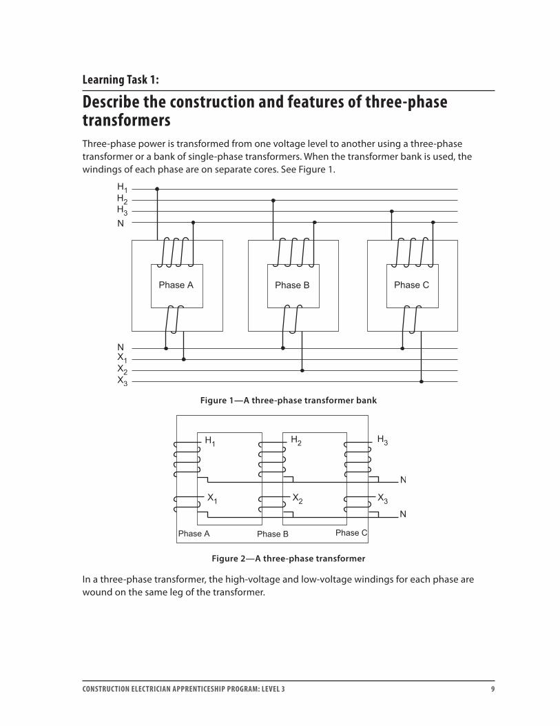
Describe the construction and features of three-phase transformersThree-phase power is transformed from one voltage level to another using a three-phase transformer or a bank of single-phase transformers. When the transformer bank is used, the windings of each phase are on separate cores. See Figure 1.
Figure 1—A three-phase transformer bank
Figure 2—A three-phase transformer
In a three-phase transformer, the high-voltage and low-voltage windings for each phase are wound on the same leg of the transformer.
LEARNING TASk 1 H-2
10 CONSTRUCTION ELECTRICIAN APPRENTICESHIP PROGRAM: LEVEL 3
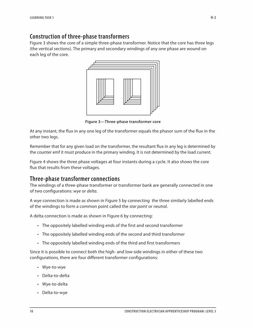
Construction of three-phase transformersFigure 3 shows the core of a simple three-phase transformer. Notice that the core has three legs (the vertical sections). The primary and secondary windings of any one phase are wound on each leg of the core.
Figure 3—Three-phase transformer core
At any instant, the flux in any one leg of the transformer equals the phasor sum of the flux in the other two legs.
Remember that for any given load on the transformer, the resultant flux in any leg is determined by the counter emf it must produce in the primary winding. It is not determined by the load current.
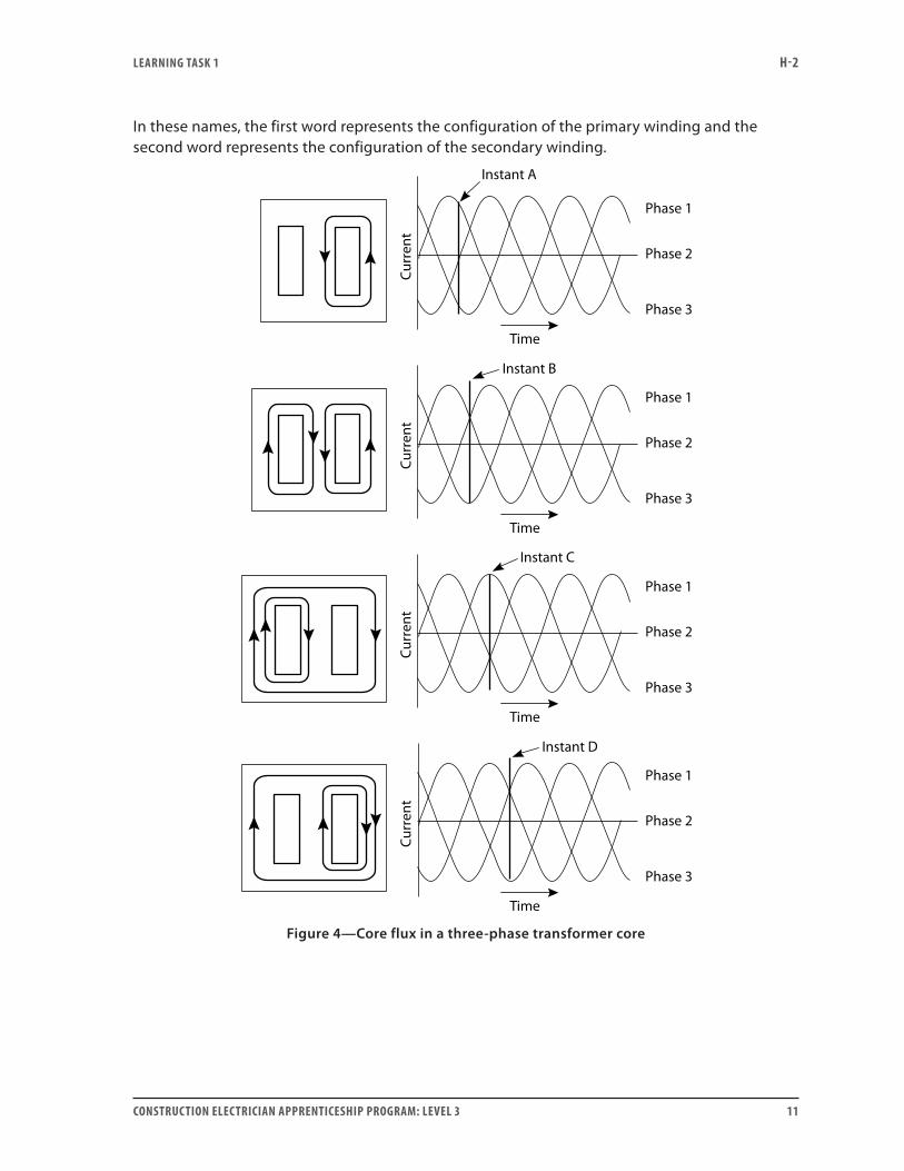
Figure 4 shows the three phase voltages at four instants during a cycle. It also shows the core flux that results from these voltages.
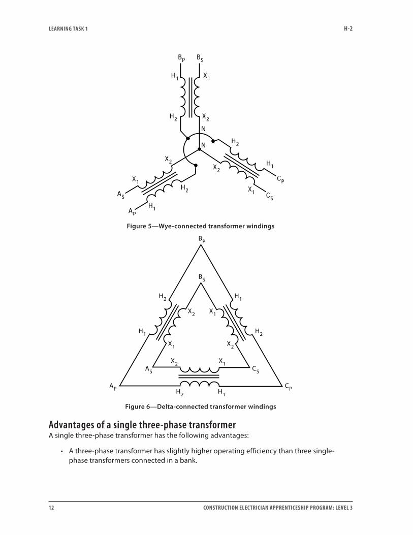
Three-phase transformer connectionsThe windings of a three-phase transformer or transformer bank are generally connected in one of two configurations: wye or delta.
A wye connection is made as shown in Figure 5 by connecting the three similarly labelled ends of the windings to form a common point called the star point or neutral.
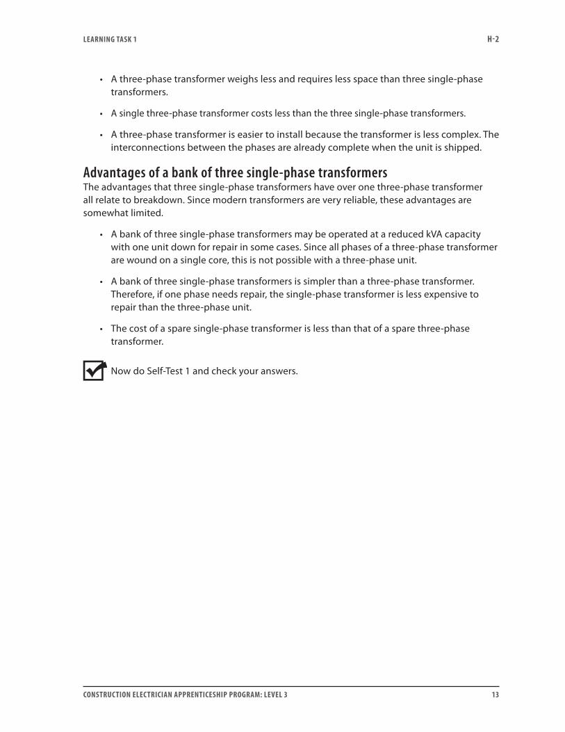
A delta connection is made as shown in Figure 6 by connecting:
• The oppositely labelled winding ends of the first and second transformer
• The oppositely labelled winding ends of the second and third transformer
• The oppositely labelled winding ends of the third and first transformers
Since it is possible to connect both the high- and low-side windings in either of these two configurations, there are four different transformer configurations:
• Wye-to-wye
• Delta-to-delta
• Wye-to-delta
• Delta-to-wye
LEARNING TASk 1 H-2
CONSTRUCTION ELECTRICIAN APPRENTICESHIP PROGRAM: LEVEL 3 11
In these names, the first word represents the configuration of the primary winding and the second word represents the configuration of the secondary winding.
Figure 4—Core flux in a three-phase transformer core
LEARNING TASk 1 H-2
12 CONSTRUCTION ELECTRICIAN APPRENTICESHIP PROGRAM: LEVEL 3
Figure 5—Wye-connected transformer windings
Figure 6—Delta-connected transformer windings
Advantages of a single three-phase transformerA single three-phase transformer has the following advantages:
• A three-phase transformer has slightly higher operating efficiency than three single-phase transformers connected in a bank.
LEARNING TASk 1 H-2
CONSTRUCTION ELECTRICIAN APPRENTICESHIP PROGRAM: LEVEL 3 13
• A three-phase transformer weighs less and requires less space than three single-phase transformers.
• A single three-phase transformer costs less than the three single-phase transformers.
• A three-phase transformer is easier to install because the transformer is less complex. The interconnections between the phases are already complete when the unit is shipped.
Advantages of a bank of three single-phase transformersThe advantages that three single-phase transformers have over one three-phase transformer all relate to breakdown. Since modern transformers are very reliable, these advantages are somewhat limited.
• A bank of three single-phase transformers may be operated at a reduced kVA capacity with one unit down for repair in some cases. Since all phases of a three-phase transformer are wound on a single core, this is not possible with a three-phase unit.
• A bank of three single-phase transformers is simpler than a three-phase transformer. Therefore, if one phase needs repair, the single-phase transformer is less expensive to repair than the three-phase unit.
• The cost of a spare single-phase transformer is less than that of a spare three-phase transformer.
Now do Self-Test 1 and check your answers.
LEARNING TASk 1 H-2
14 CONSTRUCTION ELECTRICIAN APPRENTICESHIP PROGRAM: LEVEL 3
Self-Test 1
1. List four advantages that a single, three-phase transformer has over a bank of single-phase transformers.
2. List three advantages that a bank of single-phase transformers has over a single three-phase transformer.
3. List the two common configurations in which the windings of a three-phase transformer may be connected.
Go to the Answer Key at the end of the Learning Guide to check your answers.
CONSTRUCTION ELECTRICIAN APPRENTICESHIP PROGRAM: LEVEL 3 15
Learning Task 2:
Describe the connections of three-phase transformer banksThere are four fundamental connections used for three-phase transformers (or banks). These are:
• Wye-wye connection
• Delta-delta connection
• Wye-delta connection
• Delta-wye connection
In this Learning Task, you will also look at some special delta connections. These are:
• Four-wire delta connection
• Open-delta connection
Wye-wye connectionThe wye-to-wye transformer connection is used mainly when transforming from one high voltage to another. The ability to ground the neutral point reduces the potential stress on the insulation. This means that less insulation can be used in the transformer.
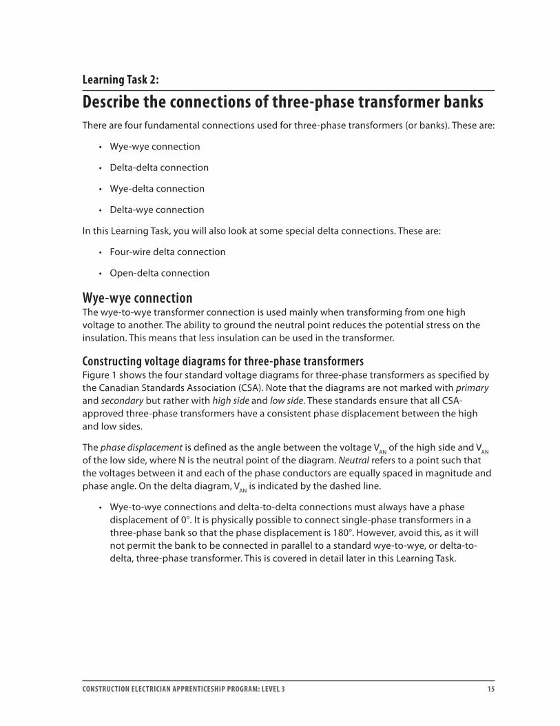
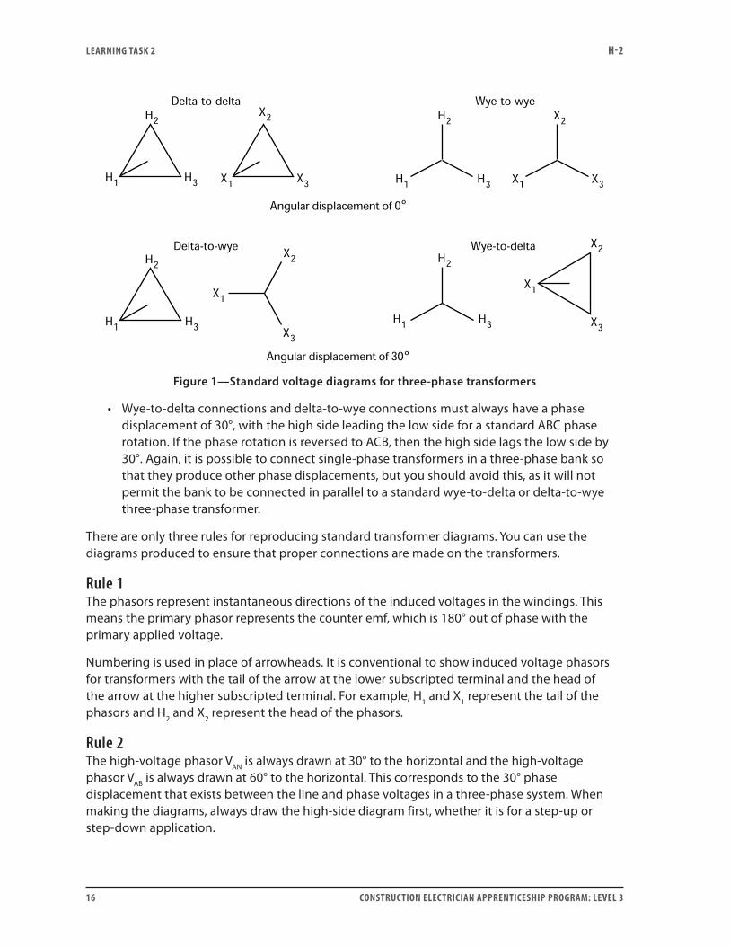
Constructing voltage diagrams for three-phase transformersFigure 1 shows the four standard voltage diagrams for three-phase transformers as specified by the Canadian Standards Association (CSA). Note that the diagrams are not marked with primary and secondary but rather with high side and low side. These standards ensure that all CSA-approved three-phase transformers have a consistent phase displacement between the high and low sides.
The phase displacement is defined as the angle between the voltage VAN of the high side and VAN of the low side, where N is the neutral point of the diagram. Neutral refers to a point such that the voltages between it and each of the phase conductors are equally spaced in magnitude and phase angle. On the delta diagram, VAN is indicated by the dashed line.
• Wye-to-wye connections and delta-to-delta connections must always have a phase displacement of 0°. It is physically possible to connect single-phase transformers in a three-phase bank so that the phase displacement is 180°. However, avoid this, as it will not permit the bank to be connected in parallel to a standard wye-to-wye, or delta-to-delta, three-phase transformer. This is covered in detail later in this Learning Task.
LEARNING TASk 2 H-2
16 CONSTRUCTION ELECTRICIAN APPRENTICESHIP PROGRAM: LEVEL 3
º
º
Figure 1—Standard voltage diagrams for three-phase transformers
• Wye-to-delta connections and delta-to-wye connections must always have a phase displacement of 30°, with the high side leading the low side for a standard ABC phase rotation. If the phase rotation is reversed to ACB, then the high side lags the low side by 30°. Again, it is possible to connect single-phase transformers in a three-phase bank so that they produce other phase displacements, but you should avoid this, as it will not permit the bank to be connected in parallel to a standard wye-to-delta or delta-to-wye three-phase transformer.
There are only three rules for reproducing standard transformer diagrams. You can use the diagrams produced to ensure that proper connections are made on the transformers.
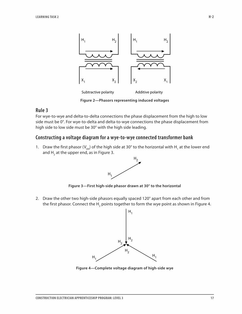
Rule 1The phasors represent instantaneous directions of the induced voltages in the windings. This means the primary phasor represents the counter emf, which is 180° out of phase with the primary applied voltage.
Numbering is used in place of arrowheads. It is conventional to show induced voltage phasors for transformers with the tail of the arrow at the lower subscripted terminal and the head of the arrow at the higher subscripted terminal. For example, H1 and X1 represent the tail of the phasors and H2 and X2 represent the head of the phasors.
Rule 2The high-voltage phasor VAN is always drawn at 30° to the horizontal and the high-voltage phasor VAB is always drawn at 60° to the horizontal. This corresponds to the 30° phase displacement that exists between the line and phase voltages in a three-phase system. When making the diagrams, always draw the high-side diagram first, whether it is for a step-up or step-down application.
LEARNING TASk 2 H-2
CONSTRUCTION ELECTRICIAN APPRENTICESHIP PROGRAM: LEVEL 3 17
Figure 2—Phasors representing induced voltages
Rule 3For wye-to-wye and delta-to-delta connections the phase displacement from the high to low side must be 0°. For wye-to-delta and delta-to-wye connections the phase displacement from high side to low side must be 30° with the high side leading.
Constructing a voltage diagram for a wye-to-wye connected transformer bank
1. Draw the first phasor (VAN) of the high side at 30° to the horizontal with H1 at the lower end and H2 at the upper end, as in Figure 3.
Figure 3—First high-side phasor drawn at 30° to the horizontal
2. Draw the other two high-side phasors equally spaced 120° apart from each other and from the first phasor. Connect the H2 points together to form the wye point as shown in Figure 4.
Figure 4—Complete voltage diagram of high-side wye
LEARNING TASk 2 H-2
18 CONSTRUCTION ELECTRICIAN APPRENTICESHIP PROGRAM: LEVEL 3
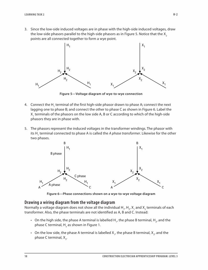
3. Since the low-side induced voltages are in phase with the high-side induced voltages, draw the low-side phasors parallel to the high-side phasors as in Figure 5. Notice that the X2 points are all connected together to form a wye point.
Figure 5—Voltage diagram of wye-to-wye connection
4. Connect the H1 terminal of the first high-side phasor drawn to phase A; connect the next lagging one to phase B; and connect the other to phase C as shown in Figure 6. Label the X1 terminals of the phasors on the low side A, B or C according to which of the high-side phasors they are in phase with.
5. The phasors represent the induced voltages in the transformer windings. The phasor with its H1 terminal connected to phase A is called the A phase transformer. Likewise for the other two phases.
Figure 6—Phase connections shown on a wye-to-wye voltage diagram
Drawing a wiring diagram from the voltage diagramNormally a voltage diagram does not show all the individual H1, H2, X1 and X2 terminals of each transformer. Also, the phase terminals are not identified as A, B and C. Instead:
• On the high side, the phase A terminal is labelled H1, the phase B terminal, H2, and the phase C terminal, H3 as shown in Figure 1.
• On the low side, the phase A terminal is labelled X1, the phase B terminal, X2, and the phase C terminal, X3.
LEARNING TASk 2 H-2
CONSTRUCTION ELECTRICIAN APPRENTICESHIP PROGRAM: LEVEL 3 19
This is also the way the terminals are labelled on a unit three-phase transformer. If present, the neutral points are labelled H0 for the high side and X0 for the low side. With the voltage diagram completed properly and the terminal information added, you can use the transformer voltage diagram to create a wiring diagram for the transformers.
The voltage diagrams are independent of the individual transformer polarities. That is, it does not matter whether the transformers used in the bank are additive polarity, subtractive polarity, or some mixture of the two. The terminals that connect to a given point depend only on their subscript identification.
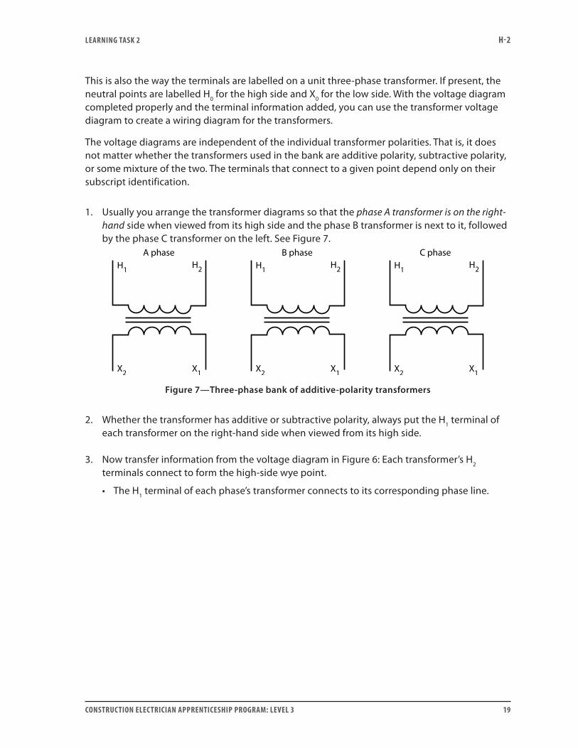
1. Usually you arrange the transformer diagrams so that the phase A transformer is on the right-hand side when viewed from its high side and the phase B transformer is next to it, followed by the phase C transformer on the left. See Figure 7.
Figure 7—Three-phase bank of additive-polarity transformers
2. Whether the transformer has additive or subtractive polarity, always put the H1 terminal of each transformer on the right-hand side when viewed from its high side.
3. Now transfer information from the voltage diagram in Figure 6: Each transformer’s H2 terminals connect to form the high-side wye point.
• The H1 terminal of each phase’s transformer connects to its corresponding phase line.
LEARNING TASk 2 H-2
20 CONSTRUCTION ELECTRICIAN APPRENTICESHIP PROGRAM: LEVEL 3
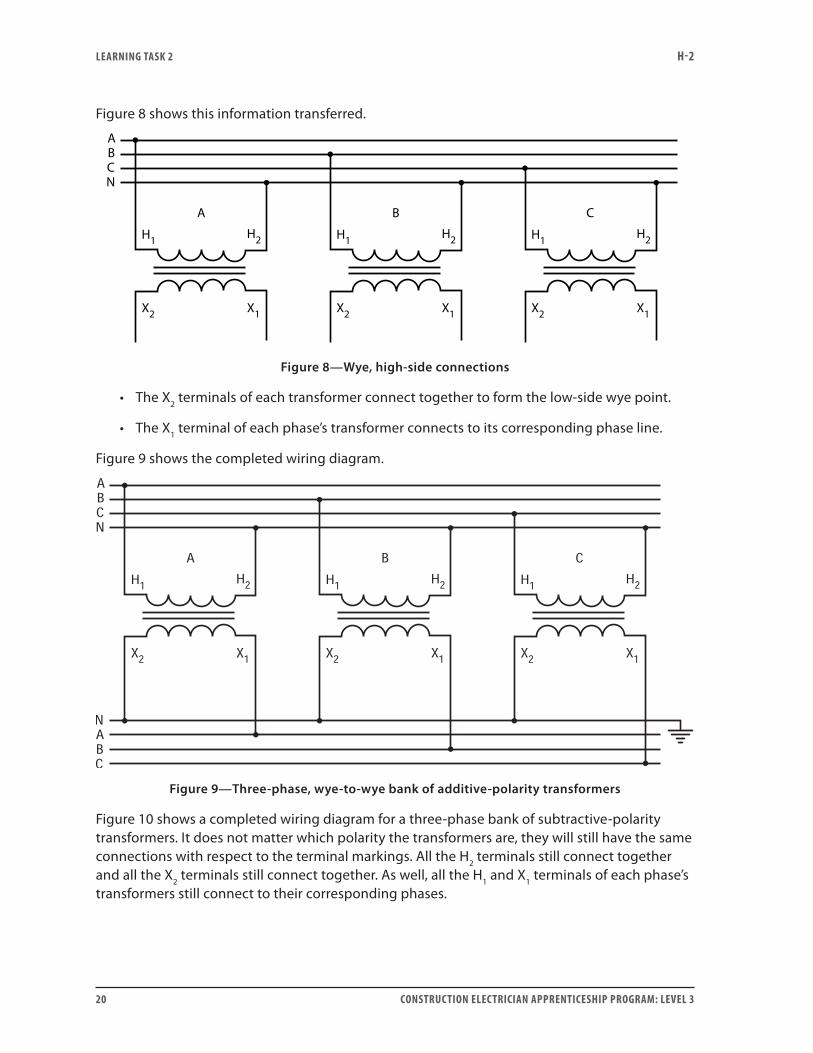
Figure 8 shows this information transferred.
Figure 8—Wye, high-side connections
• The X2 terminals of each transformer connect together to form the low-side wye point.
• The X1 terminal of each phase’s transformer connects to its corresponding phase line.
Figure 9 shows the completed wiring diagram.
Figure 9—Three-phase, wye-to-wye bank of additive-polarity transformers
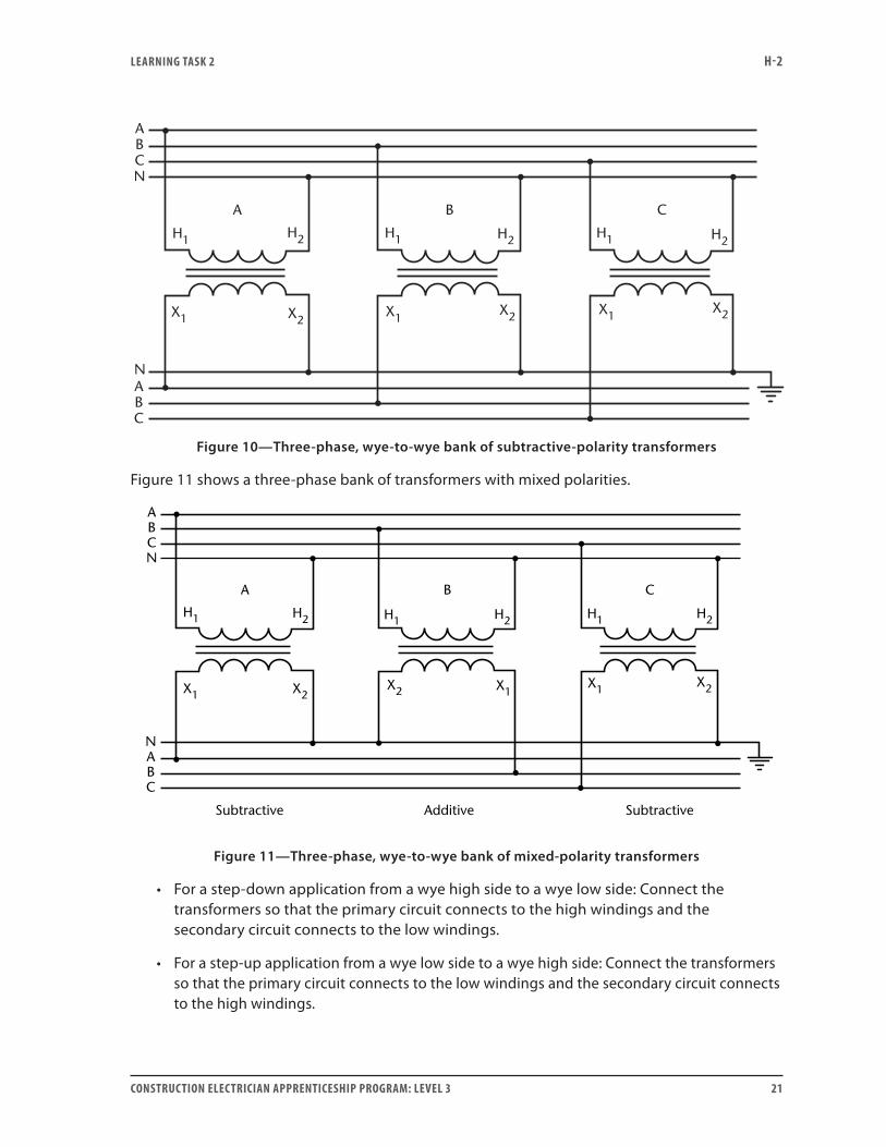
Figure 10 shows a completed wiring diagram for a three-phase bank of subtractive-polarity transformers. It does not matter which polarity the transformers are, they will still have the same connections with respect to the terminal markings. All the H2 terminals still connect together and all the X2 terminals still connect together. As well, all the H1 and X1 terminals of each phase’s transformers still connect to their corresponding phases.
LEARNING TASk 2 H-2
CONSTRUCTION ELECTRICIAN APPRENTICESHIP PROGRAM: LEVEL 3 21
H1 H2
X1 X2
A
ABCN
B C
H1 H1H2 H2
X1X1X2
X2
NABC
Figure 10—Three-phase, wye-to-wye bank of subtractive-polarity transformers
Figure 11 shows a three-phase bank of transformers with mixed polarities.
H1 H2
X2X1
A
ABCN
NABC
B C
Subtractive Additive Subtractive
H1 H1H2 H2
X1X1X2
X2
Figure 11—Three-phase, wye-to-wye bank of mixed-polarity transformers
• For a step-down application from a wye high side to a wye low side: Connect the transformers so that the primary circuit connects to the high windings and the secondary circuit connects to the low windings.
• For a step-up application from a wye low side to a wye high side: Connect the transformers so that the primary circuit connects to the low windings and the secondary circuit connects to the high windings.
LEARNING TASk 2 H-2
22 CONSTRUCTION ELECTRICIAN APPRENTICESHIP PROGRAM: LEVEL 3
Voltage relationships for the wye-to-wye transformer bank• The line-to-line voltage-transformation ratio is exactly the same as the individual
transformer’s turns ratio for a wye-to-wye connection.
• The voltage ratings of the transformer’s primary and secondaries must be equal to the corresponding line voltages divided by 3.
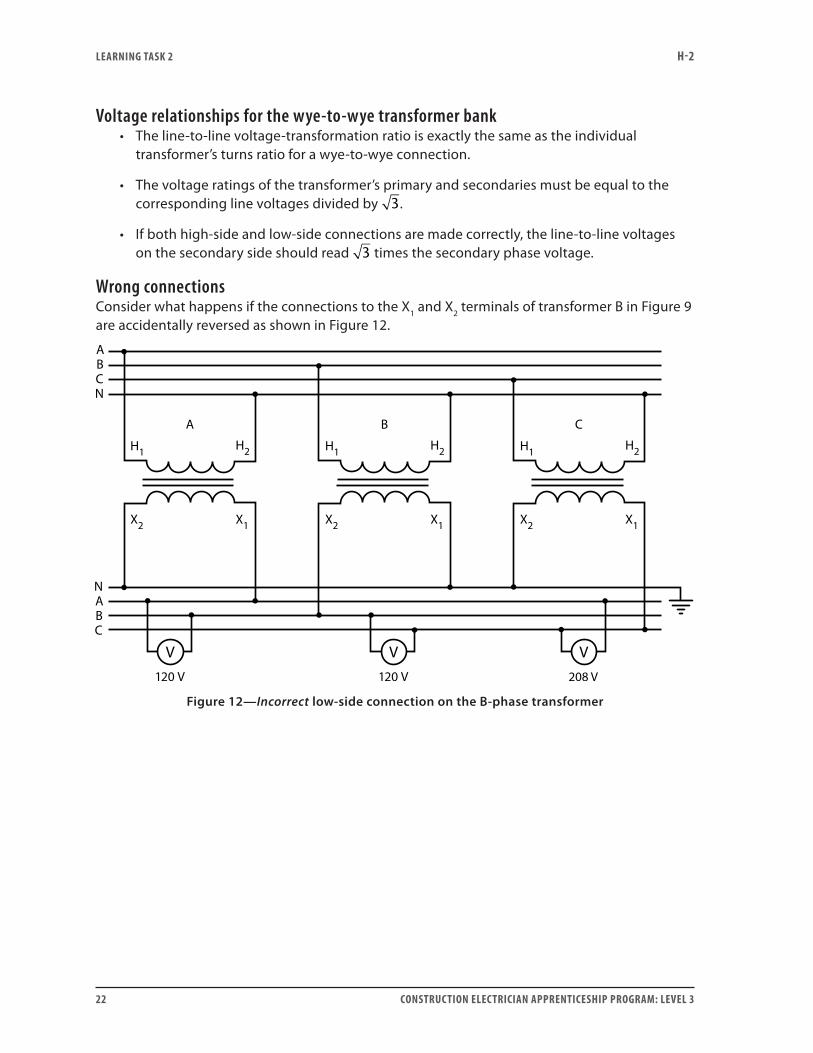
• If both high-side and low-side connections are made correctly, the line-to-line voltages on the secondary side should read 3 times the secondary phase voltage.
Wrong connectionsConsider what happens if the connections to the X1 and X2 terminals of transformer B in Figure 9 are accidentally reversed as shown in Figure 12.
Figure 12—Incorrect low-side connection on the B-phase transformer
LEARNING TASk 2 H-2
CONSTRUCTION ELECTRICIAN APPRENTICESHIP PROGRAM: LEVEL 3 23
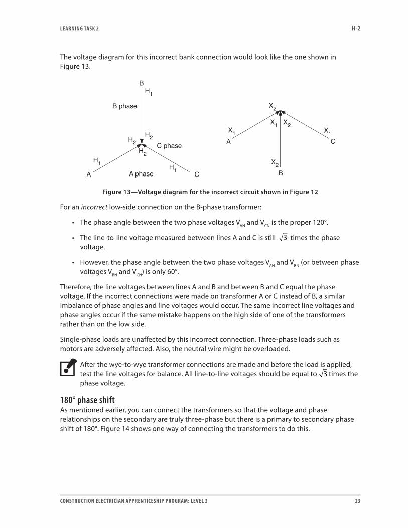
The voltage diagram for this incorrect bank connection would look like the one shown in Figure 13.
H1
H2
H2
H2
H1 H1
X1
X2
X1 X1
B phase
B
CA
A C
A phase
C phase
X2
X2B
Figure 13—Voltage diagram for the incorrect circuit shown in Figure 12
For an incorrect low-side connection on the B-phase transformer:
• The phase angle between the two phase voltages VAN and VCN is the proper 120°.
• The line-to-line voltage measured between lines A and C is still 3 times the phase voltage.
• However, the phase angle between the two phase voltages VAN and VBN (or between phase voltages VBN and VCN) is only 60°.
Therefore, the line voltages between lines A and B and between B and C equal the phase voltage. If the incorrect connections were made on transformer A or C instead of B, a similar imbalance of phase angles and line voltages would occur. The same incorrect line voltages and phase angles occur if the same mistake happens on the high side of one of the transformers rather than on the low side.
Single-phase loads are unaffected by this incorrect connection. Three-phase loads such as motors are adversely affected. Also, the neutral wire might be overloaded.
After the wye-to-wye transformer connections are made and before the load is applied, test the line voltages for balance. All line-to-line voltages should be equal to 3 times the phase voltage.
180° phase shiftAs mentioned earlier, you can connect the transformers so that the voltage and phase relationships on the secondary are truly three-phase but there is a primary to secondary phase shift of 180°. Figure 14 shows one way of connecting the transformers to do this.
LEARNING TASk 2 H-2
24 CONSTRUCTION ELECTRICIAN APPRENTICESHIP PROGRAM: LEVEL 3
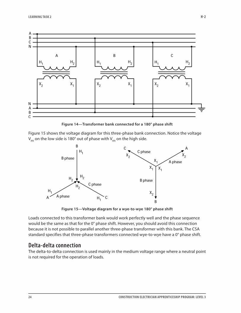
Figure 14—Transformer bank connected for a 180° phase shift
Figure 15 shows the voltage diagram for this three-phase bank connection. Notice the voltage VAN on the low side is 180° out of phase with VAN on the high side.
Figure 15—Voltage diagram for a wye-to-wye 180° phase shift
Loads connected to this transformer bank would work perfectly well and the phase sequence would be the same as that for the 0° phase shift. However, you should avoid this connection because it is not possible to parallel another three-phase transformer with this bank. The CSA standard specifies that three-phase transformers connected wye-to-wye have a 0° phase shift.
Delta-delta connectionThe delta-to-delta connection is used mainly in the medium voltage range where a neutral point is not required for the operation of loads.
LEARNING TASk 2 H-2
CONSTRUCTION ELECTRICIAN APPRENTICESHIP PROGRAM: LEVEL 3 25
Constructing a voltage diagram To construct a voltage diagram for a delta-to-delta connected transformer, do the following:
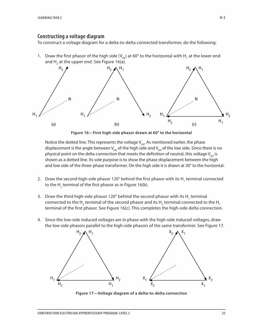
1. Draw the first phasor of the high side (VAB) at 60° to the horizontal with H1 at the lower end and H2 at the upper end. See Figure 16(a).
Figure 16—First high-side phasor drawn at 60° to the horizontal
Notice the dotted line. This represents the voltage VAN. As mentioned earlier, the phase displacement is the angle between VAN of the high side and VAN of the low side. Since there is no physical point on the delta connection that meets the definition of neutral, this voltage VAN is shown as a dotted line. Its sole purpose is to show the phase displacement between the high and low side of the three-phase transformer. On the high side it is drawn at 30° to the horizontal.
2. Draw the second high-side phasor 120° behind the first phasor with its H1 terminal connected to the H2 terminal of the first phasor as in Figure 16(b).
3. Draw the third high-side phasor 120° behind the second phasor with its H1 terminal connected to the H2 terminal of the second phasor and its H2 terminal connected to the H1 terminal of the first phasor. See Figure 16(c). This completes the high-side delta connection.
4. Since the low-side induced voltages are in phase with the high-side induced voltages, draw the low-side phasors parallel to the high-side phasors of the same transformer. See Figure 17.
Figure 17—Voltage diagram of a delta-to-delta connection
LEARNING TASk 2 H-2
26 CONSTRUCTION ELECTRICIAN APPRENTICESHIP PROGRAM: LEVEL 3
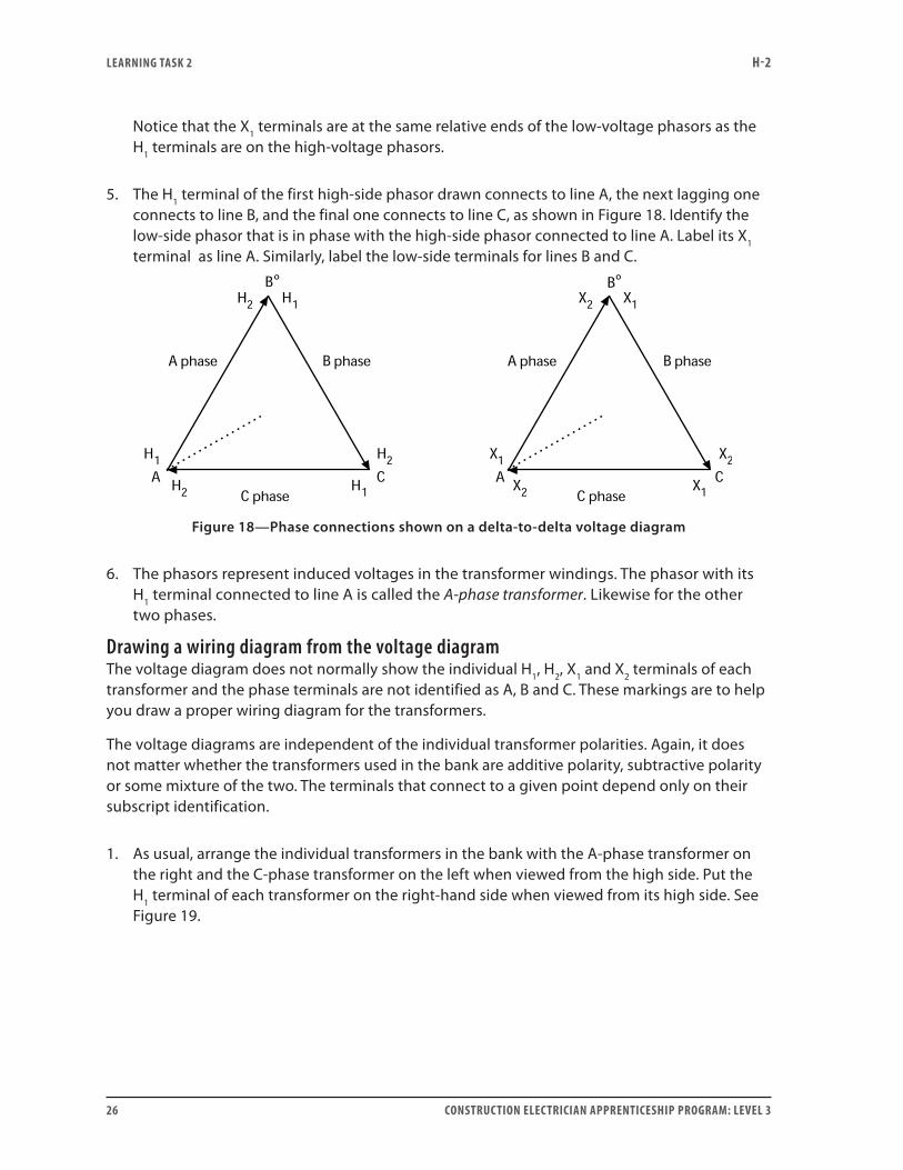
Notice that the X1 terminals are at the same relative ends of the low-voltage phasors as the H1 terminals are on the high-voltage phasors.
5. The H1 terminal of the first high-side phasor drawn connects to line A, the next lagging one connects to line B, and the final one connects to line C, as shown in Figure 18. Identify the low-side phasor that is in phase with the high-side phasor connected to line A. Label its X1 terminal as line A. Similarly, label the low-side terminals for lines B and C.
º º
Figure 18—Phase connections shown on a delta-to-delta voltage diagram
6. The phasors represent induced voltages in the transformer windings. The phasor with its H1 terminal connected to line A is called the A-phase transformer. Likewise for the other two phases.
Drawing a wiring diagram from the voltage diagramThe voltage diagram does not normally show the individual H1, H2, X1 and X2 terminals of each transformer and the phase terminals are not identified as A, B and C. These markings are to help you draw a proper wiring diagram for the transformers.
The voltage diagrams are independent of the individual transformer polarities. Again, it does not matter whether the transformers used in the bank are additive polarity, subtractive polarity or some mixture of the two. The terminals that connect to a given point depend only on their subscript identification.
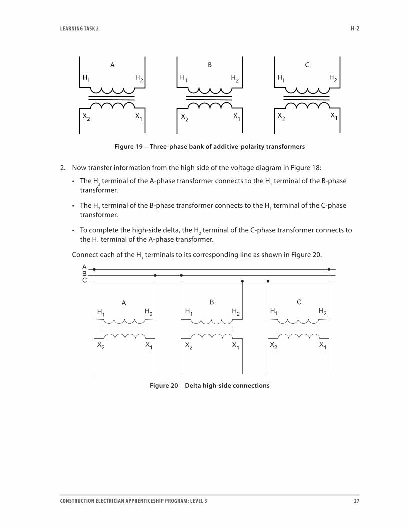
1. As usual, arrange the individual transformers in the bank with the A-phase transformer on the right and the C-phase transformer on the left when viewed from the high side. Put the H1 terminal of each transformer on the right-hand side when viewed from its high side. See Figure 19.
LEARNING TASk 2 H-2
CONSTRUCTION ELECTRICIAN APPRENTICESHIP PROGRAM: LEVEL 3 27
X1X2
A B
H1 H2 H1 H1
C
H2H2
X1X2X2 X1
Figure 19—Three-phase bank of additive-polarity transformers
2. Now transfer information from the high side of the voltage diagram in Figure 18:
• The H2 terminal of the A-phase transformer connects to the H1 terminal of the B-phase transformer.
• The H2 terminal of the B-phase transformer connects to the H1 terminal of the C-phase transformer.
• To complete the high-side delta, the H2 terminal of the C-phase transformer connects to the H1 terminal of the A-phase transformer.
Connect each of the H1 terminals to its corresponding line as shown in Figure 20.
Figure 20—Delta high-side connections
LEARNING TASk 2 H-2
28 CONSTRUCTION ELECTRICIAN APPRENTICESHIP PROGRAM: LEVEL 3
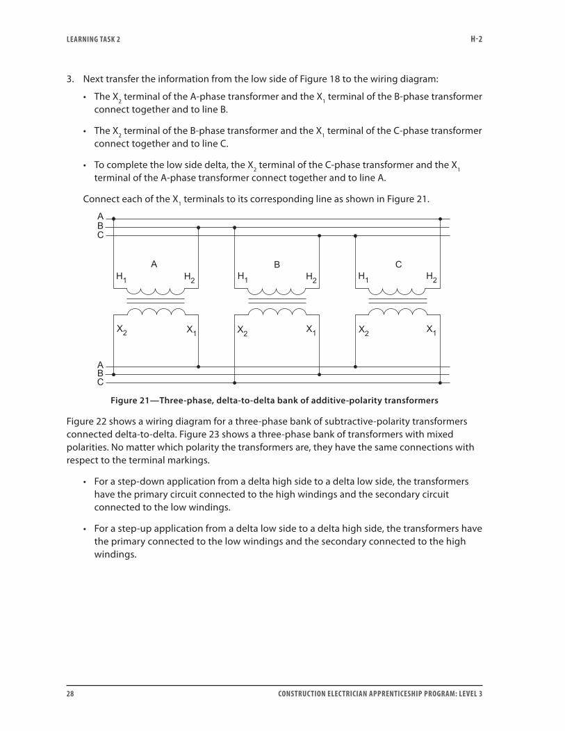
3. Next transfer the information from the low side of Figure 18 to the wiring diagram:
• The X2 terminal of the A-phase transformer and the X1 terminal of the B-phase transformer connect together and to line B.
• The X2 terminal of the B-phase transformer and the X1 terminal of the C-phase transformer connect together and to line C.
• To complete the low side delta, the X2 terminal of the C-phase transformer and the X1 terminal of the A-phase transformer connect together and to line A.
Connect each of the X1 terminals to its corresponding line as shown in Figure 21.
Figure 21—Three-phase, delta-to-delta bank of additive-polarity transformers
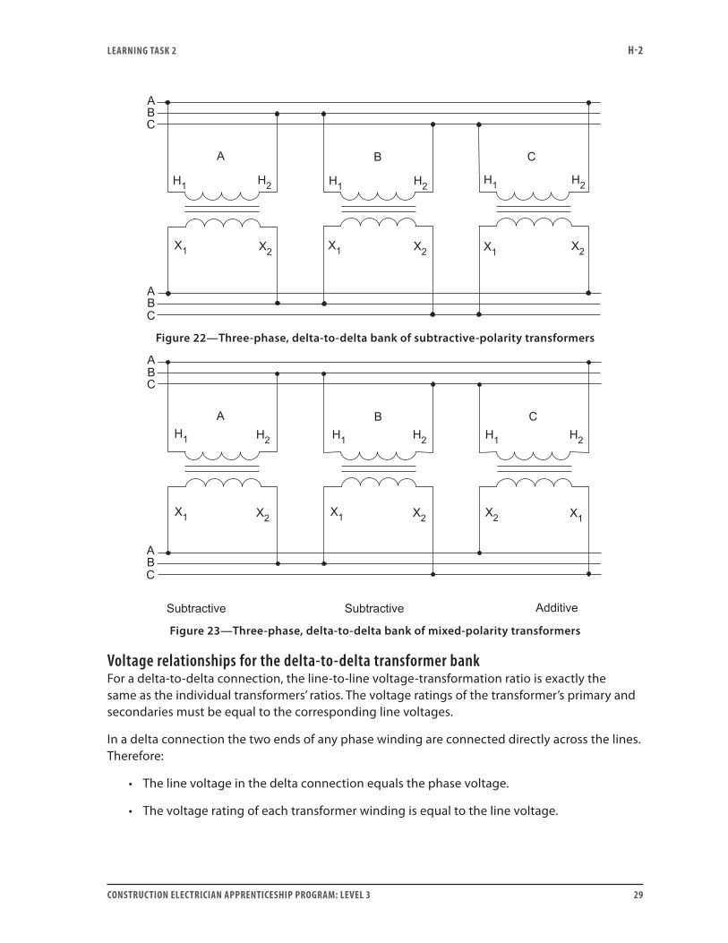
Figure 22 shows a wiring diagram for a three-phase bank of subtractive-polarity transformers connected delta-to-delta. Figure 23 shows a three-phase bank of transformers with mixed polarities. No matter which polarity the transformers are, they have the same connections with respect to the terminal markings.
• For a step-down application from a delta high side to a delta low side, the transformers have the primary circuit connected to the high windings and the secondary circuit connected to the low windings.
• For a step-up application from a delta low side to a delta high side, the transformers have the primary connected to the low windings and the secondary connected to the high windings.
LEARNING TASk 2 H-2
CONSTRUCTION ELECTRICIAN APPRENTICESHIP PROGRAM: LEVEL 3 29
Figure 22—Three-phase, delta-to-delta bank of subtractive-polarity transformers
Figure 23—Three-phase, delta-to-delta bank of mixed-polarity transformers
Voltage relationships for the delta-to-delta transformer bankFor a delta-to-delta connection, the line-to-line voltage-transformation ratio is exactly the same as the individual transformers’ ratios. The voltage ratings of the transformer’s primary and secondaries must be equal to the corresponding line voltages.
In a delta connection the two ends of any phase winding are connected directly across the lines. Therefore:
• The line voltage in the delta connection equals the phase voltage.
• The voltage rating of each transformer winding is equal to the line voltage.
LEARNING TASk 2 H-2
30 CONSTRUCTION ELECTRICIAN APPRENTICESHIP PROGRAM: LEVEL 3
For this reason, a different type of voltmeter test must be performed on a secondary delta connection to determine if all the connections are properly made. This test is referred to as the mesh or delta-closure test.
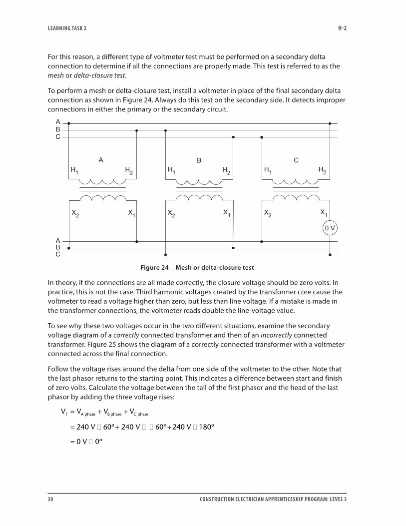
To perform a mesh or delta-closure test, install a voltmeter in place of the final secondary delta connection as shown in Figure 24. Always do this test on the secondary side. It detects improper connections in either the primary or the secondary circuit.
Figure 24—Mesh or delta-closure test
In theory, if the connections are all made correctly, the closure voltage should be zero volts. In practice, this is not the case. Third harmonic voltages created by the transformer core cause the voltmeter to read a voltage higher than zero, but less than line voltage. If a mistake is made in the transformer connections, the voltmeter reads double the line-voltage value.
To see why these two voltages occur in the two different situations, examine the secondary voltage diagram of a correctly connected transformer and then of an incorrectly connected transformer. Figure 25 shows the diagram of a correctly connected transformer with a voltmeter connected across the final connection.
Follow the voltage rises around the delta from one side of the voltmeter to the other. Note that the last phasor returns to the starting point. This indicates a difference between start and finish of zero volts. Calculate the voltage between the tail of the first phasor and the head of the last phasor by adding the three voltage rises:
V V V V
V V
T A phase B phase C phase= + +
= � + � � +240 60 240 60 2º º 440 180
0 0
V
V
�
= �
º
º
LEARNING TASk 2 H-2
CONSTRUCTION ELECTRICIAN APPRENTICESHIP PROGRAM: LEVEL 3 31
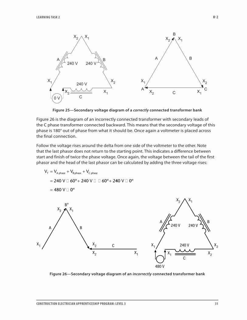
Figure 25—Secondary voltage diagram of a correctly connected transformer bank
Figure 26 is the diagram of an incorrectly connected transformer with secondary leads of the C phase transformer connected backward. This means that the secondary voltage of this phase is 180° out of phase from what it should be. Once again a voltmeter is placed across the final connection.
Follow the voltage rises around the delta from one side of the voltmeter to the other. Note that the last phasor does not return to the starting point. This indicates a difference between start and finish of twice the phase voltage. Once again, the voltage between the tail of the first phasor and the head of the last phasor can be calculated by adding the three voltage rises:
V V V V
V V
T A phase B phase C phase= + +
= � + � � +240 60 240 60 2º º 440 0
480 0
V
V
�
= �
º
º
º
Figure 26—Secondary voltage diagram of an incorrectly connected transformer bank
LEARNING TASk 2 H-2
32 CONSTRUCTION ELECTRICIAN APPRENTICESHIP PROGRAM: LEVEL 3
If the incorrect connections are made on the primary rather than the secondary, the same 180° phase shift occurs and the voltmeter still reads 480 V. If there is an incorrect connection and you make the last connection before doing a voltmeter test, it can result in a disastrous short circuit across 480 V.
Always do this voltmeter test before making the secondary closure connection.
Whether the incorrect connection is made on the primary or the secondary, always correct it before you replace the voltmeter by the final connection.
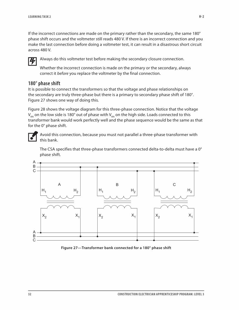
180° phase shiftIt is possible to connect the transformers so that the voltage and phase relationships on the secondary are truly three-phase but there is a primary to secondary phase shift of 180°. Figure 27 shows one way of doing this.
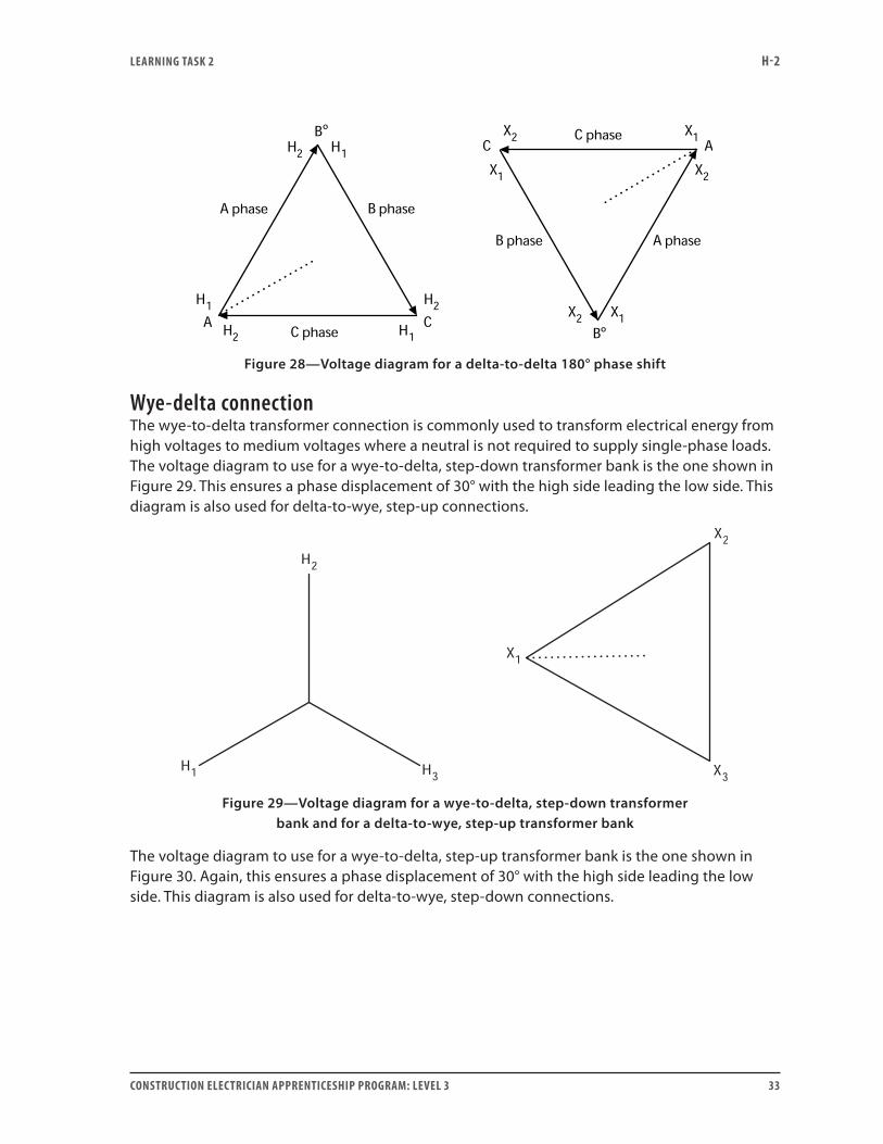
Figure 28 shows the voltage diagram for this three-phase connection. Notice that the voltage VAN on the low side is 180° out of phase with VAN on the high side. Loads connected to this transformer bank would work perfectly well and the phase sequence would be the same as that for the 0° phase shift.
Avoid this connection, because you must not parallel a three-phase transformer with this bank.
The CSA specifies that three-phase transformers connected delta-to-delta must have a 0° phase shift.
Figure 27—Transformer bank connected for a 180° phase shift
LEARNING TASk 2 H-2
CONSTRUCTION ELECTRICIAN APPRENTICESHIP PROGRAM: LEVEL 3 33
º
º
Figure 28—Voltage diagram for a delta-to-delta 180° phase shift
Wye-delta connectionThe wye-to-delta transformer connection is commonly used to transform electrical energy from high voltages to medium voltages where a neutral is not required to supply single-phase loads. The voltage diagram to use for a wye-to-delta, step-down transformer bank is the one shown in Figure 29. This ensures a phase displacement of 30° with the high side leading the low side. This diagram is also used for delta-to-wye, step-up connections.
Figure 29—Voltage diagram for a wye-to-delta, step-down transformer bank and for a delta-to-wye, step-up transformer bank
The voltage diagram to use for a wye-to-delta, step-up transformer bank is the one shown in Figure 30. Again, this ensures a phase displacement of 30° with the high side leading the low side. This diagram is also used for delta-to-wye, step-down connections.
LEARNING TASk 2 H-2
34 CONSTRUCTION ELECTRICIAN APPRENTICESHIP PROGRAM: LEVEL 3
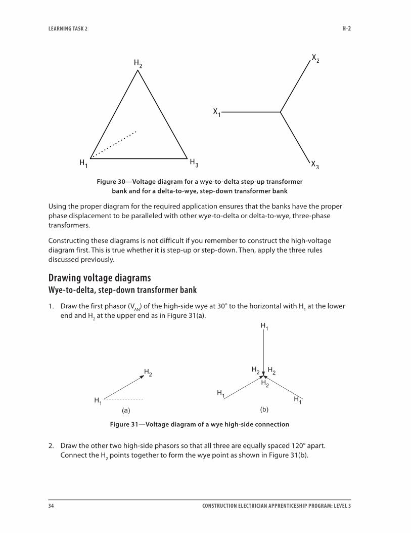
Figure 30—Voltage diagram for a wye-to-delta step-up transformer bank and for a delta-to-wye, step-down transformer bank
Using the proper diagram for the required application ensures that the banks have the proper phase displacement to be paralleled with other wye-to-delta or delta-to-wye, three-phase transformers.
Constructing these diagrams is not difficult if you remember to construct the high-voltage diagram first. This is true whether it is step-up or step-down. Then, apply the three rules discussed previously.
Drawing voltage diagrams Wye-to-delta, step-down transformer bank
1. Draw the first phasor (VAN) of the high-side wye at 30° to the horizontal with H1 at the lower end and H2 at the upper end as in Figure 31(a).
Figure 31—Voltage diagram of a wye high-side connection
2. Draw the other two high-side phasors so that all three are equally spaced 120° apart. Connect the H2 points together to form the wye point as shown in Figure 31(b).
LEARNING TASk 2 H-2
CONSTRUCTION ELECTRICIAN APPRENTICESHIP PROGRAM: LEVEL 3 35
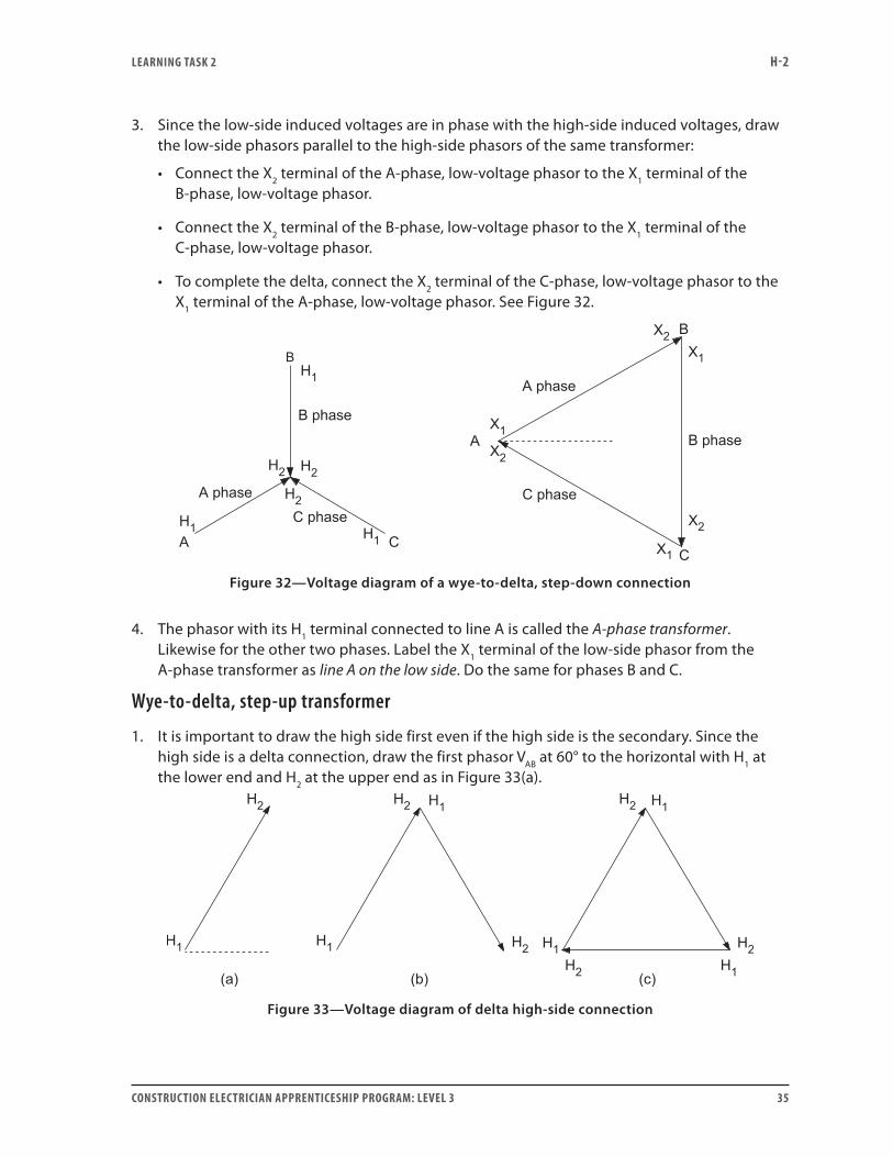
3. Since the low-side induced voltages are in phase with the high-side induced voltages, draw the low-side phasors parallel to the high-side phasors of the same transformer:
• Connect the X2 terminal of the A-phase, low-voltage phasor to the X1 terminal of the B-phase, low-voltage phasor.
• Connect the X2 terminal of the B-phase, low-voltage phasor to the X1 terminal of the C-phase, low-voltage phasor.
• To complete the delta, connect the X2 terminal of the C-phase, low-voltage phasor to the X1 terminal of the A-phase, low-voltage phasor. See Figure 32.
Figure 32—Voltage diagram of a wye-to-delta, step-down connection
4. The phasor with its H1 terminal connected to line A is called the A-phase transformer. Likewise for the other two phases. Label the X1 terminal of the low-side phasor from the A-phase transformer as line A on the low side. Do the same for phases B and C.
Wye-to-delta, step-up transformer
1. It is important to draw the high side first even if the high side is the secondary. Since the high side is a delta connection, draw the first phasor VAB at 60° to the horizontal with H1 at the lower end and H2 at the upper end as in Figure 33(a).
Figure 33—Voltage diagram of delta high-side connection
LEARNING TASk 2 H-2
36 CONSTRUCTION ELECTRICIAN APPRENTICESHIP PROGRAM: LEVEL 3
2. Draw the second high-side phasor 120° behind the first phasor, with its H1 terminal connected to the H2 terminal of the first phasor as in Figure 33(b).
3. Draw the third high-side phasor 120° behind the second phasor, with its H1 terminal connected to the H2 terminal of the second phasor. To complete the high-side delta connection, connect its H2 terminal to the H1 terminal of the first phasor as shown in Figure 33(c).
4. Since the low-side induced voltages are in phase with the high-side induced voltages, draw the low-side phasors parallel to the high-side phasors of the same transformer. To ensure the proper phase displacement of 30°, you will have to connect the X1 terminals of the low-side phasors to form the neutral or wye point. See Figure 34.
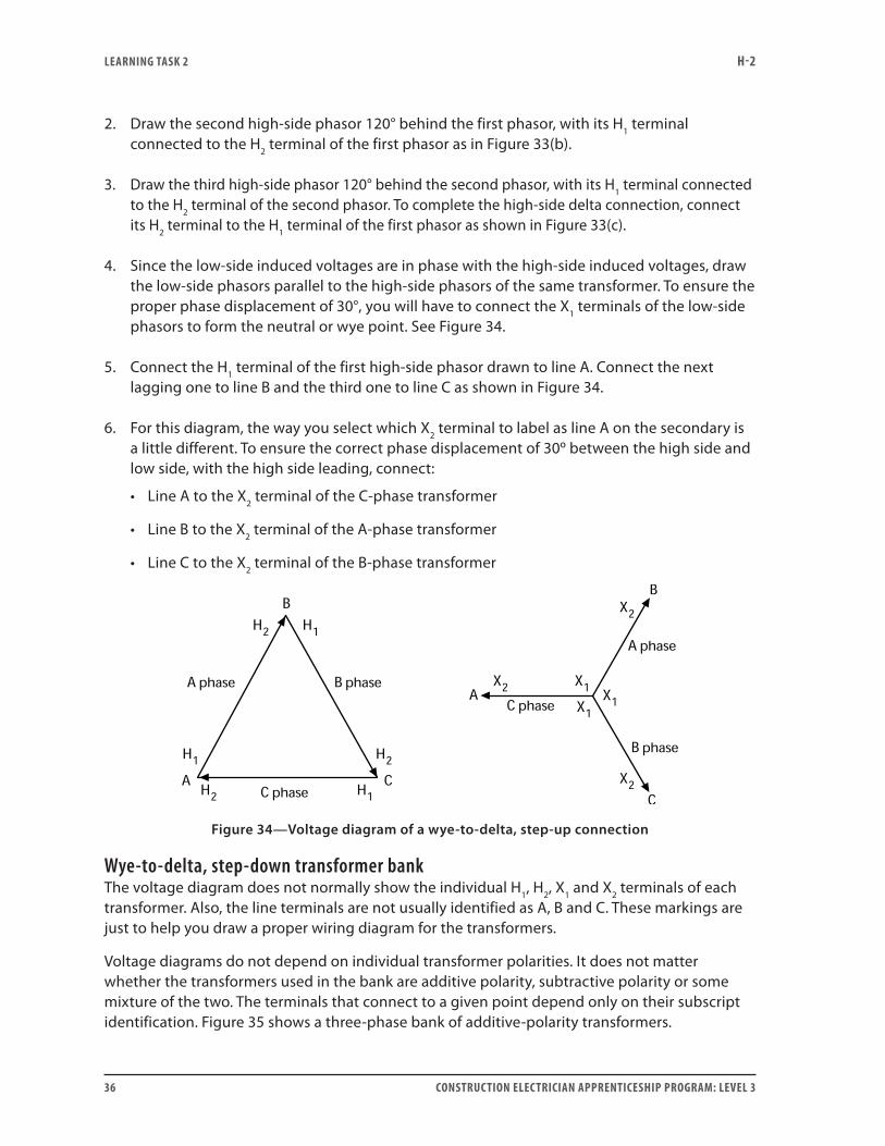
5. Connect the H1 terminal of the first high-side phasor drawn to line A. Connect the next lagging one to line B and the third one to line C as shown in Figure 34.
6. For this diagram, the way you select which X2 terminal to label as line A on the secondary is a little different. To ensure the correct phase displacement of 30º between the high side and low side, with the high side leading, connect:
• Line A to the X2 terminal of the C-phase transformer
• Line B to the X2 terminal of the A-phase transformer
• Line C to the X2 terminal of the B-phase transformer
Figure 34—Voltage diagram of a wye-to-delta, step-up connection
Wye-to-delta, step-down transformer bankThe voltage diagram does not normally show the individual H1, H2, X1 and X2 terminals of each transformer. Also, the line terminals are not usually identified as A, B and C. These markings are just to help you draw a proper wiring diagram for the transformers.
Voltage diagrams do not depend on individual transformer polarities. It does not matter whether the transformers used in the bank are additive polarity, subtractive polarity or some mixture of the two. The terminals that connect to a given point depend only on their subscript identification. Figure 35 shows a three-phase bank of additive-polarity transformers.
LEARNING TASk 2 H-2
CONSTRUCTION ELECTRICIAN APPRENTICESHIP PROGRAM: LEVEL 3 37
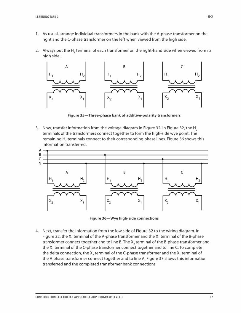
1. As usual, arrange individual transformers in the bank with the A-phase transformer on the right and the C-phase transformer on the left when viewed from the high side.
2. Always put the H1 terminal of each transformer on the right-hand side when viewed from its high side.
X1X2
A B
H1 H2 H1 H1
C
H2H2
X1X2X2 X1
Figure 35—Three-phase bank of additive-polarity transformers
3. Now, transfer information from the voltage diagram in Figure 32. In Figure 32, the H2 terminals of the transformers connect together to form the high-side wye point. The remaining H1 terminals connect to their corresponding phase lines. Figure 36 shows this information transferred.
Figure 36—Wye high-side connections
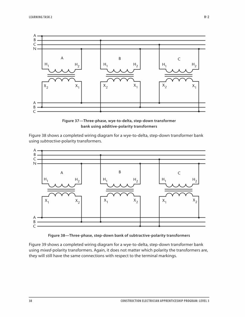
4. Next, transfer the information from the low side of Figure 32 to the wiring diagram. In Figure 32, the X2 terminal of the A-phase transformer and the X1 terminal of the B-phase transformer connect together and to line B. The X2 terminal of the B-phase transformer and the X1 terminal of the C-phase transformer connect together and to line C. To complete the delta connection, the X2 terminal of the C-phase transformer and the X1 terminal of the A phase transformer connect together and to line A. Figure 37 shows this information transferred and the completed transformer bank connections.
LEARNING TASk 2 H-2
38 CONSTRUCTION ELECTRICIAN APPRENTICESHIP PROGRAM: LEVEL 3
X2
ABCN
ABC
X1X2 X2X1X1
H1 H1 H1 H2H2H2
A B C
Figure 37—Three-phase, wye-to-delta, step-down transformer bank using additive-polarity transformers
Figure 38 shows a completed wiring diagram for a wye-to-delta, step-down transformer bank using subtractive-polarity transformers.
H1
A
ABCN
ABC
H1 H1H2 H2 H2
X2X2 X2X1X1X1
B C
Figure 38—Three-phase, step-down bank of subtractive-polarity transformers
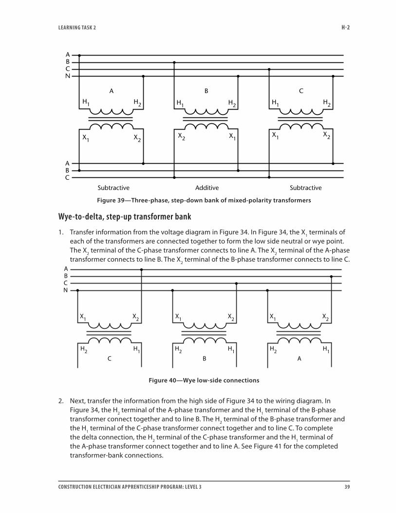
Figure 39 shows a completed wiring diagram for a wye-to-delta, step-down transformer bank using mixed-polarity transformers. Again, it does not matter which polarity the transformers are, they will still have the same connections with respect to the terminal markings.
LEARNING TASk 2 H-2
CONSTRUCTION ELECTRICIAN APPRENTICESHIP PROGRAM: LEVEL 3 39
H1 H2
X2X1
A
ABCN
ABC
B C
Subtractive Additive Subtractive
H1 H1H2 H2
X1X1X2
X2
Figure 39—Three-phase, step-down bank of mixed-polarity transformers
Wye-to-delta, step-up transformer bank
1. Transfer information from the voltage diagram in Figure 34. In Figure 34, the X1 terminals of each of the transformers are connected together to form the low side neutral or wye point. The X2 terminal of the C-phase transformer connects to line A. The X2 terminal of the A-phase transformer connects to line B. The X2 terminal of the B-phase transformer connects to line C.
Figure 40—Wye low-side connections
2. Next, transfer the information from the high side of Figure 34 to the wiring diagram. In Figure 34, the H2 terminal of the A-phase transformer and the H1 terminal of the B-phase transformer connect together and to line B. The H2 terminal of the B-phase transformer and the H1 terminal of the C-phase transformer connect together and to line C. To complete the delta connection, the H2 terminal of the C-phase transformer and the H1 terminal of the A-phase transformer connect together and to line A. See Figure 41 for the completed transformer-bank connections.
LEARNING TASk 2 H-2
40 CONSTRUCTION ELECTRICIAN APPRENTICESHIP PROGRAM: LEVEL 3
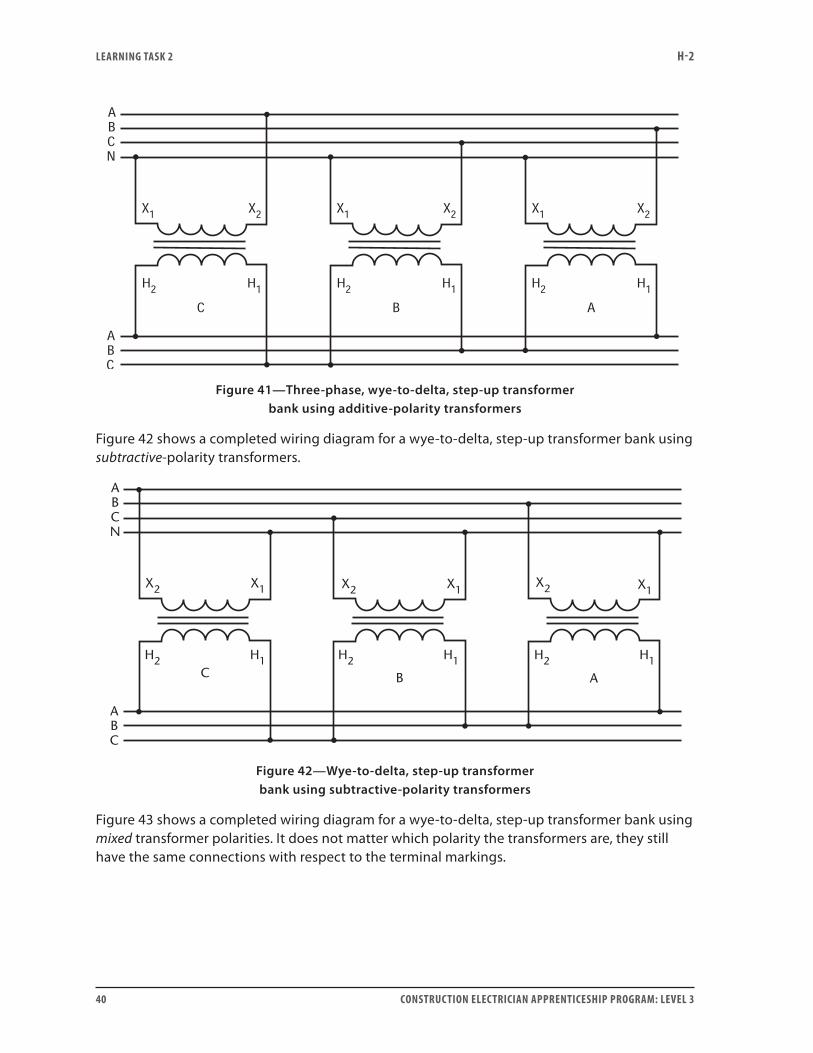
Figure 41—Three-phase, wye-to-delta, step-up transformer bank using additive-polarity transformers
Figure 42 shows a completed wiring diagram for a wye-to-delta, step-up transformer bank using subtractive-polarity transformers.
H1H2
X1X2
H1H2 H1H2
A
ABCN
ABC
BC
X1X2 X1X2
Figure 42—Wye-to-delta, step-up transformer bank using subtractive-polarity transformers
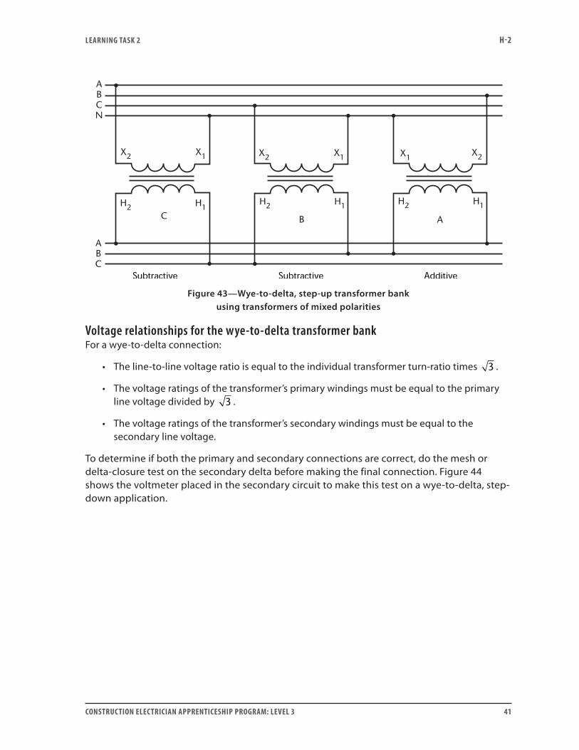
Figure 43 shows a completed wiring diagram for a wye-to-delta, step-up transformer bank using mixed transformer polarities. It does not matter which polarity the transformers are, they still have the same connections with respect to the terminal markings.
LEARNING TASk 2 H-2
CONSTRUCTION ELECTRICIAN APPRENTICESHIP PROGRAM: LEVEL 3 41
H1H2
X1X2
A
ABCN
ABC
BC
X1X2 X1 X2
H1H2 H1H2
Figure 43—Wye-to-delta, step-up transformer bank using transformers of mixed polarities
Voltage relationships for the wye-to-delta transformer bankFor a wye-to-delta connection:
• The line-to-line voltage ratio is equal to the individual transformer turn-ratio times 3 .
• The voltage ratings of the transformer’s primary windings must be equal to the primary line voltage divided by 3 .
• The voltage ratings of the transformer’s secondary windings must be equal to the secondary line voltage.
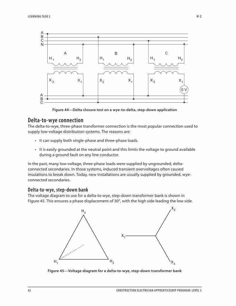
To determine if both the primary and secondary connections are correct, do the mesh or delta-closure test on the secondary delta before making the final connection. Figure 44 shows the voltmeter placed in the secondary circuit to make this test on a wye-to-delta, step-down application.
LEARNING TASk 2 H-2
42 CONSTRUCTION ELECTRICIAN APPRENTICESHIP PROGRAM: LEVEL 3
Figure 44—Delta closure test on a wye-to-delta, step-down application
Delta-to-wye connectionThe delta-to-wye, three-phase transformer connection is the most popular connection used to supply low-voltage distribution systems. The reasons are:
• It can supply both single-phase and three-phase loads.
• It is easily grounded at the neutral point and this limits the voltage to ground available during a ground fault on any line conductor.
In the past, many low-voltage, three-phase loads were supplied by ungrounded, delta-connected secondaries. In those systems, induced transient overvoltages often caused insulations to break down. Today, new installations are usually supplied by grounded, wye-connected secondaries.
Delta-to-wye, step-down bankThe voltage diagram to use for a delta-to-wye, step-down transformer bank is shown in Figure 45. This ensures a phase displacement of 30°, with the high side leading the low side.
Figure 45—Voltage diagram for a delta-to-wye, step-down transformer bank
LEARNING TASk 2 H-2
CONSTRUCTION ELECTRICIAN APPRENTICESHIP PROGRAM: LEVEL 3 43
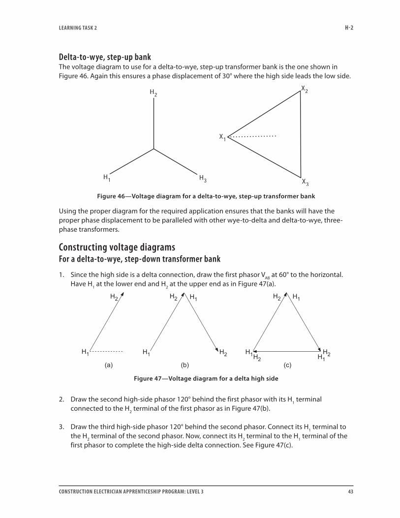
Delta-to-wye, step-up bankThe voltage diagram to use for a delta-to-wye, step-up transformer bank is the one shown in Figure 46. Again this ensures a phase displacement of 30° where the high side leads the low side.
Figure 46—Voltage diagram for a delta-to-wye, step-up transformer bank
Using the proper diagram for the required application ensures that the banks will have the proper phase displacement to be paralleled with other wye-to-delta and delta-to-wye, three-phase transformers.
Constructing voltage diagramsFor a delta-to-wye, step-down transformer bank
1. Since the high side is a delta connection, draw the first phasor VAB at 60° to the horizontal. Have H1 at the lower end and H2 at the upper end as in Figure 47(a).
Figure 47—Voltage diagram for a delta high side
2. Draw the second high-side phasor 120° behind the first phasor with its H1 terminal connected to the H2 terminal of the first phasor as in Figure 47(b).
3. Draw the third high-side phasor 120° behind the second phasor. Connect its H1 terminal to the H2 terminal of the second phasor. Now, connect its H2 terminal to the H1 terminal of the first phasor to complete the high-side delta connection. See Figure 47(c).
LEARNING TASk 2 H-2
44 CONSTRUCTION ELECTRICIAN APPRENTICESHIP PROGRAM: LEVEL 3
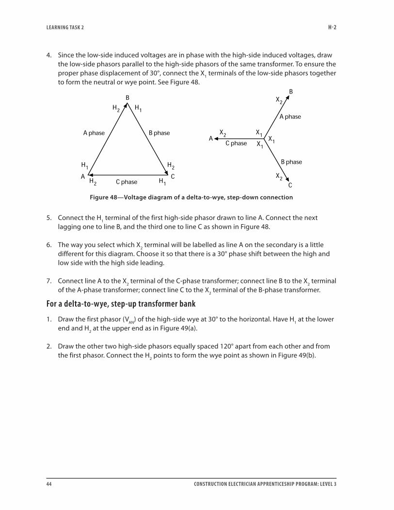
4. Since the low-side induced voltages are in phase with the high-side induced voltages, draw the low-side phasors parallel to the high-side phasors of the same transformer. To ensure the proper phase displacement of 30°, connect the X1 terminals of the low-side phasors together to form the neutral or wye point. See Figure 48.
Figure 48—Voltage diagram of a delta-to-wye, step-down connection
5. Connect the H1 terminal of the first high-side phasor drawn to line A. Connect the next lagging one to line B, and the third one to line C as shown in Figure 48.
6. The way you select which X2 terminal will be labelled as line A on the secondary is a little different for this diagram. Choose it so that there is a 30° phase shift between the high and low side with the high side leading.
7. Connect line A to the X2 terminal of the C-phase transformer; connect line B to the X2 terminal of the A-phase transformer; connect line C to the X2 terminal of the B-phase transformer.
For a delta-to-wye, step-up transformer bank
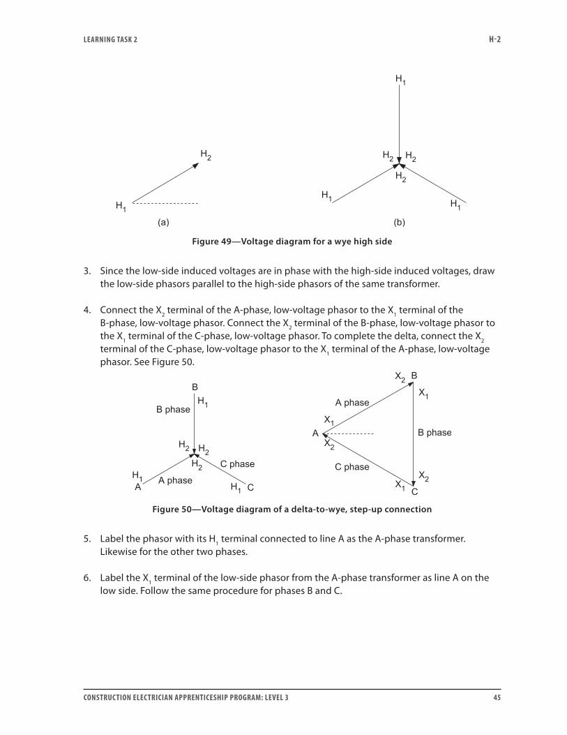
1. Draw the first phasor (VAN) of the high-side wye at 30° to the horizontal. Have H1 at the lower end and H2 at the upper end as in Figure 49(a).
2. Draw the other two high-side phasors equally spaced 120° apart from each other and from the first phasor. Connect the H2 points to form the wye point as shown in Figure 49(b).
LEARNING TASk 2 H-2
CONSTRUCTION ELECTRICIAN APPRENTICESHIP PROGRAM: LEVEL 3 45
Figure 49—Voltage diagram for a wye high side
3. Since the low-side induced voltages are in phase with the high-side induced voltages, draw the low-side phasors parallel to the high-side phasors of the same transformer.
4. Connect the X2 terminal of the A-phase, low-voltage phasor to the X1 terminal of the B-phase, low-voltage phasor. Connect the X2 terminal of the B-phase, low-voltage phasor to the X1 terminal of the C-phase, low-voltage phasor. To complete the delta, connect the X2 terminal of the C-phase, low-voltage phasor to the X1 terminal of the A-phase, low-voltage phasor. See Figure 50.
Figure 50—Voltage diagram of a delta-to-wye, step-up connection
5. Label the phasor with its H1 terminal connected to line A as the A-phase transformer. Likewise for the other two phases.
6. Label the X1 terminal of the low-side phasor from the A-phase transformer as line A on the low side. Follow the same procedure for phases B and C.
LEARNING TASk 2 H-2
46 CONSTRUCTION ELECTRICIAN APPRENTICESHIP PROGRAM: LEVEL 3
Drawing wiring diagramsFor a delta-to-wye, step-down transformer bankThe voltage diagram does not normally show the individual H1, H2, X1 and X2 terminals of each transformer and the line terminals are not identified as A, B and C. These markings are simply to help you draw a proper wiring diagram.
The voltage diagrams are independent of the individual transformer polarities. It does not matter whether the transformers used in the bank are additive polarity, subtractive polarity or some mixture of the two. The terminals that connect to a given point depend only upon their subscript identification.
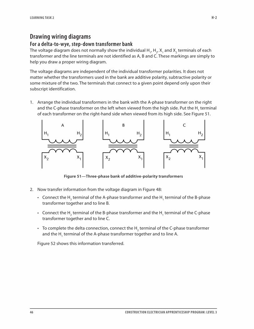
1. Arrange the individual transformers in the bank with the A-phase transformer on the right and the C-phase transformer on the left when viewed from the high side. Put the H1 terminal of each transformer on the right-hand side when viewed from its high side. See Figure 51.
X1X2
A B
H1 H2 H1 H1
C
H2H2
X1X2X2 X1
Figure 51—Three-phase bank of additive-polarity transformers
2. Now transfer information from the voltage diagram in Figure 48:
• Connect the H2 terminal of the A-phase transformer and the H1 terminal of the B-phase transformer together and to line B.
• Connect the H2 terminal of the B-phase transformer and the H1 terminal of the C-phase transformer together and to line C.
• To complete the delta connection, connect the H2 terminal of the C-phase transformer and the H1 terminal of the A-phase transformer together and to line A.
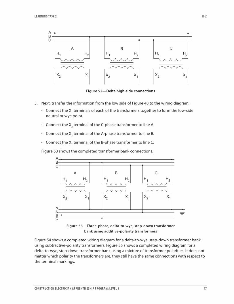
Figure 52 shows this information transferred.
LEARNING TASk 2 H-2
CONSTRUCTION ELECTRICIAN APPRENTICESHIP PROGRAM: LEVEL 3 47
Figure 52—Delta high-side connections
3. Next, transfer the information from the low side of Figure 48 to the wiring diagram:
• Connect the X1 terminals of each of the transformers together to form the low-side neutral or wye point.
• Connect the X2 terminal of the C-phase transformer to line A.
• Connect the X2 terminal of the A-phase transformer to line B.
• Connect the X2 terminal of the B-phase transformer to line C.
Figure 53 shows the completed transformer bank connections.
Figure 53—Three-phase, delta-to-wye, step-down transformer bank using additive-polarity transformers
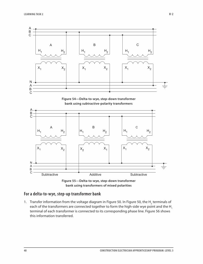
Figure 54 shows a completed wiring diagram for a delta-to-wye, step-down transformer bank using subtractive-polarity transformers. Figure 55 shows a completed wiring diagram for a delta-to-wye, step-down transformer bank using a mixture of transformer polarities. It does not matter which polarity the transformers are, they still have the same connections with respect to the terminal markings.
LEARNING TASk 2 H-2
48 CONSTRUCTION ELECTRICIAN APPRENTICESHIP PROGRAM: LEVEL 3
Figure 54—Delta-to-wye, step-down transformer bank using subtractive-polarity transformers
Figure 55—Delta-to-wye, step-down transformer bank using transformers of mixed polarities
For a delta-to-wye, step-up transformer bank
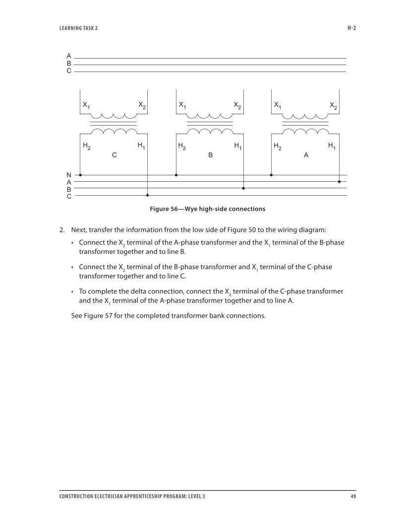
1. Transfer information from the voltage diagram in Figure 50. In Figure 50, the H2 terminals of each of the transformers are connected together to form the high-side wye point and the H1 terminal of each transformer is connected to its corresponding phase line. Figure 56 shows this information transferred.
LEARNING TASk 2 H-2
CONSTRUCTION ELECTRICIAN APPRENTICESHIP PROGRAM: LEVEL 3 49
Figure 56—Wye high-side connections
2. Next, transfer the information from the low side of Figure 50 to the wiring diagram:
• Connect the X2 terminal of the A-phase transformer and the X1 terminal of the B-phase transformer together and to line B.
• Connect the X2 terminal of the B-phase transformer and X1 terminal of the C-phase transformer together and to line C.
• To complete the delta connection, connect the X2 terminal of the C-phase transformer and the X1 terminal of the A-phase transformer together and to line A.
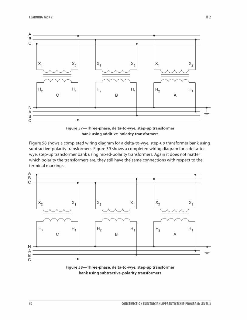
See Figure 57 for the completed transformer bank connections.
LEARNING TASk 2 H-2
50 CONSTRUCTION ELECTRICIAN APPRENTICESHIP PROGRAM: LEVEL 3
Figure 57—Three-phase, delta-to-wye, step-up transformer bank using additive-polarity transformers
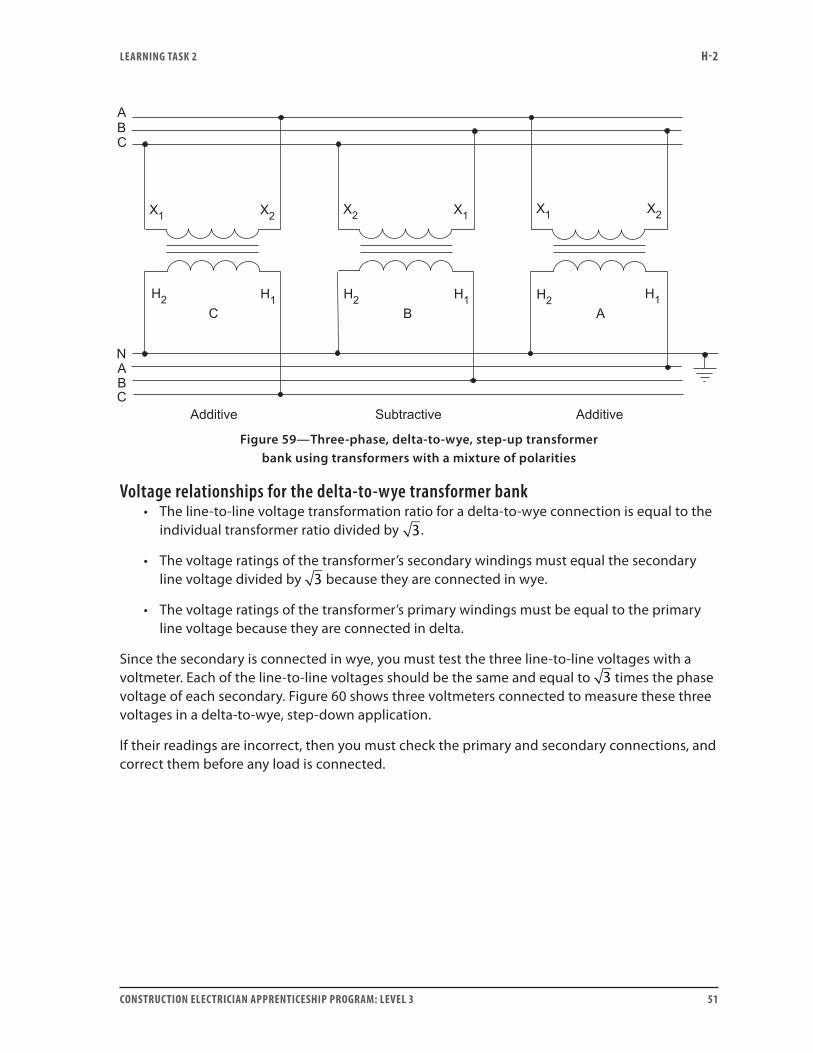
Figure 58 shows a completed wiring diagram for a delta-to-wye, step-up transformer bank using subtractive-polarity transformers. Figure 59 shows a completed wiring diagram for a delta-to-wye, step-up transformer bank using mixed-polarity transformers. Again it does not matter which polarity the transformers are, they still have the same connections with respect to the terminal markings.
Figure 58—Three-phase, delta-to-wye, step-up transformer bank using subtractive-polarity transformers
LEARNING TASk 2 H-2
CONSTRUCTION ELECTRICIAN APPRENTICESHIP PROGRAM: LEVEL 3 51
Figure 59—Three-phase, delta-to-wye, step-up transformer bank using transformers with a mixture of polarities
Voltage relationships for the delta-to-wye transformer bank• The line-to-line voltage transformation ratio for a delta-to-wye connection is equal to the
individual transformer ratio divided by 3.
• The voltage ratings of the transformer’s secondary windings must equal the secondary line voltage divided by 3 because they are connected in wye.
• The voltage ratings of the transformer’s primary windings must be equal to the primary line voltage because they are connected in delta.
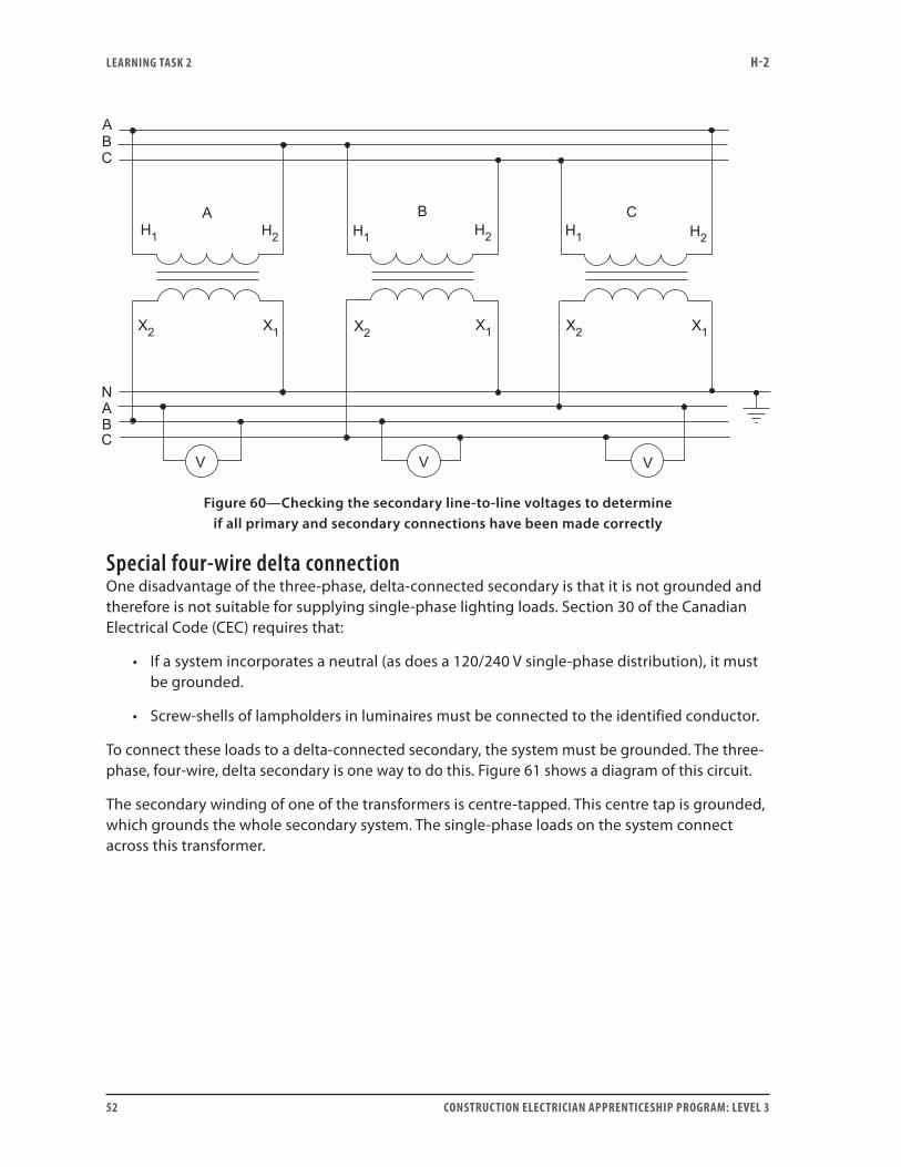
Since the secondary is connected in wye, you must test the three line-to-line voltages with a voltmeter. Each of the line-to-line voltages should be the same and equal to 3 times the phase voltage of each secondary. Figure 60 shows three voltmeters connected to measure these three voltages in a delta-to-wye, step-down application.
If their readings are incorrect, then you must check the primary and secondary connections, and correct them before any load is connected.
LEARNING TASk 2 H-2
52 CONSTRUCTION ELECTRICIAN APPRENTICESHIP PROGRAM: LEVEL 3
Figure 60—Checking the secondary line-to-line voltages to determine if all primary and secondary connections have been made correctly
Special four-wire delta connectionOne disadvantage of the three-phase, delta-connected secondary is that it is not grounded and therefore is not suitable for supplying single-phase lighting loads. Section 30 of the Canadian Electrical Code (CEC) requires that:
• If a system incorporates a neutral (as does a 120/240 V single-phase distribution), it must be grounded.
• Screw-shells of lampholders in luminaires must be connected to the identified conductor.
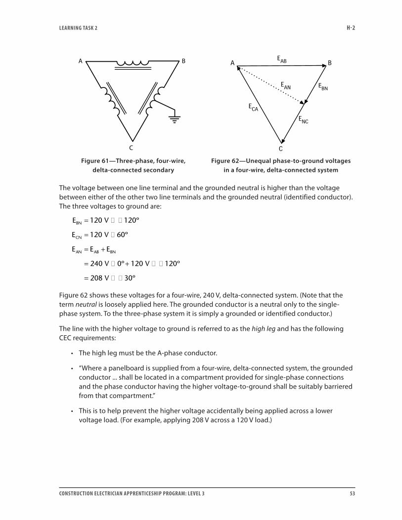
To connect these loads to a delta-connected secondary, the system must be grounded. The three-phase, four-wire, delta secondary is one way to do this. Figure 61 shows a diagram of this circuit.
The secondary winding of one of the transformers is centre-tapped. This centre tap is grounded, which grounds the whole secondary system. The single-phase loads on the system connect across this transformer.
LEARNING TASk 2 H-2
CONSTRUCTION ELECTRICIAN APPRENTICESHIP PROGRAM: LEVEL 3 53
A B
C
Figure 61—Three-phase, four-wire, delta-connected secondary
Figure 62—Unequal phase-to-ground voltages in a four-wire, delta-connected system
The voltage between one line terminal and the grounded neutral is higher than the voltage between either of the other two line terminals and the grounded neutral (identified conductor). The three voltages to ground are:
E V
E V
E E E
V
BN
CN
AN AB BN
= � �
= �
= +
=
120 120
120 60
240
º
º
� + � �
= � �
0 120 120
208 30
º º
º
V
V
Figure 62 shows these voltages for a four-wire, 240 V, delta-connected system. (Note that the term neutral is loosely applied here. The grounded conductor is a neutral only to the single-phase system. To the three-phase system it is simply a grounded or identified conductor.)
The line with the higher voltage to ground is referred to as the high leg and has the following CEC requirements:
• The high leg must be the A-phase conductor.
• “Where a panelboard is supplied from a four-wire, delta-connected system, the grounded conductor ... shall be located in a compartment provided for single-phase connections and the phase conductor having the higher voltage-to-ground shall be suitably barriered from that compartment.”
• This is to help prevent the higher voltage accidentally being applied across a lower voltage load. (For example, applying 208 V across a 120 V load.)
LEARNING TASk 2 H-2
54 CONSTRUCTION ELECTRICIAN APPRENTICESHIP PROGRAM: LEVEL 3
• The voltage between the high leg and ground is always 3
2 times the line-to-line voltage.
For example, in this case:
32
240 208� =V V
• Also, the voltage between each of the other two lines and ground is 1/2 times the line-to-line voltage. For example, in this case:
12
240 120� =V V
When you size transformers for this kind of bank, you must be aware that the transformer with the centre tap supplies only 2/3 of the current to the single-phase load. The other 1/3 must be carried by each of the other two transformers.
When transformers of different kVA ratings are used in this type of bank, the maximum safe bank rating is three times the kVA rating of the smallest unit.
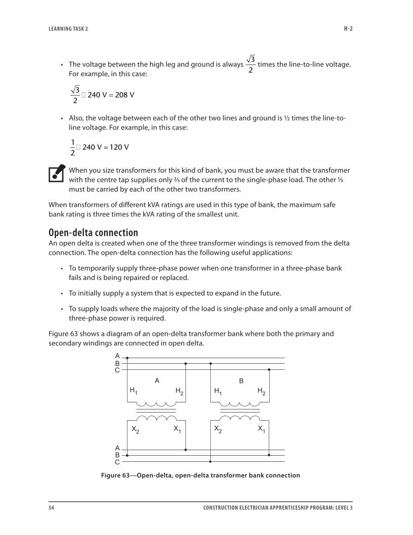
Open-delta connectionAn open delta is created when one of the three transformer windings is removed from the delta connection. The open-delta connection has the following useful applications:
• To temporarily supply three-phase power when one transformer in a three-phase bank fails and is being repaired or replaced.
• To initially supply a system that is expected to expand in the future.
• To supply loads where the majority of the load is single-phase and only a small amount of three-phase power is required.
Figure 63 shows a diagram of an open-delta transformer bank where both the primary and secondary windings are connected in open delta.
Figure 63—Open-delta, open-delta transformer bank connection
LEARNING TASk 2 H-2
CONSTRUCTION ELECTRICIAN APPRENTICESHIP PROGRAM: LEVEL 3 55
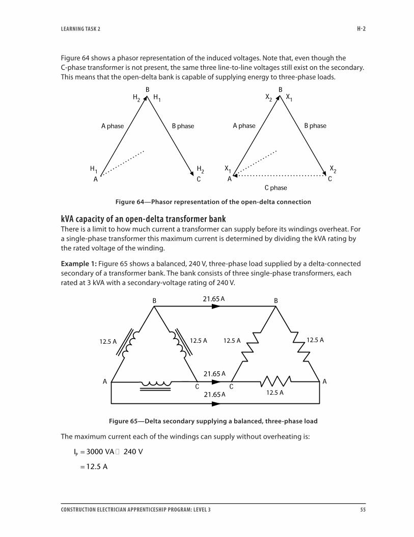
Figure 64 shows a phasor representation of the induced voltages. Note that, even though the C-phase transformer is not present, the same three line-to-line voltages still exist on the secondary. This means that the open-delta bank is capable of supplying energy to three-phase loads.
Figure 64—Phasor representation of the open-delta connection
kVA capacity of an open-delta transformer bankThere is a limit to how much current a transformer can supply before its windings overheat. For a single-phase transformer this maximum current is determined by dividing the kVA rating by the rated voltage of the winding.
Example 1: Figure 65 shows a balanced, 240 V, three-phase load supplied by a delta-connected secondary of a transformer bank. The bank consists of three single-phase transformers, each rated at 3 kVA with a secondary-voltage rating of 240 V.
21.65
21.65
21.65
Figure 65—Delta secondary supplying a balanced, three-phase load
The maximum current each of the windings can supply without overheating is:
I VA V
A
P = �
=
3000 240
12 5.
LEARNING TASk 2 H-2
56 CONSTRUCTION ELECTRICIAN APPRENTICESHIP PROGRAM: LEVEL 3
If each phase winding is capable of supplying 12.5 A, then at full load the line current is:
I A
A
L = �
=
3 12 5
21 65
.
.
The maximum three-phase load the bank is capable of supplying is:
kVA E I
V A
kVA
MAX L L= � � �
= � � �
=
3 1000
3 240 21 65 1000
9
.
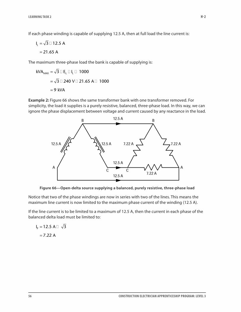
Example 2: Figure 66 shows the same transformer bank with one transformer removed. For simplicity, the load it supplies is a purely resistive, balanced, three-phase load. In this way, we can ignore the phase displacement between voltage and current caused by any reactance in the load.
Figure 66—Open-delta source supplying a balanced, purely resistive, three-phase load
Notice that two of the phase windings are now in series with two of the lines. This means the maximum line current is now limited to the maximum phase current of the winding (12.5 A).
If the line current is to be limited to a maximum of 12.5 A, then the current in each phase of the balanced delta load must be limited to:
I A
A
P = �
=
12 5 3
7 22
.
.
LEARNING TASk 2 H-2
CONSTRUCTION ELECTRICIAN APPRENTICESHIP PROGRAM: LEVEL 3 57
It might seem that this open-delta bank could supply 2/3 of the power of a complete bank to a balanced three-phase load. But this is not the case. The total apparent power this open-delta bank can supply to a balanced, three-phase load is:
kVA E I
V A
kVA
MAX L L= � � �
= � � �
=
3 1000
3 240 12 5 1000
5 2
.
.
Comparing Examples 1 and 2, note that 5.2 kVA = 57.7% of 9 kVA1. An open-delta transformer bank can supply only 57.7% as much power to a balanced three-phase load as a closed-delta bank can. This also corresponds to only 86.6% of the combined capacity of the two transformers in the open-delta bank.
Line current in an open-delta secondary circuitApplying Kirchhoff’s current law in Figure 66 at the junction of the two transformer windings with line B, it looks at first as though the current in line B cannot be 12.5 A when the currents in line A and line C are also 12.5 A. However, you must remember that these three currents are not in phase.
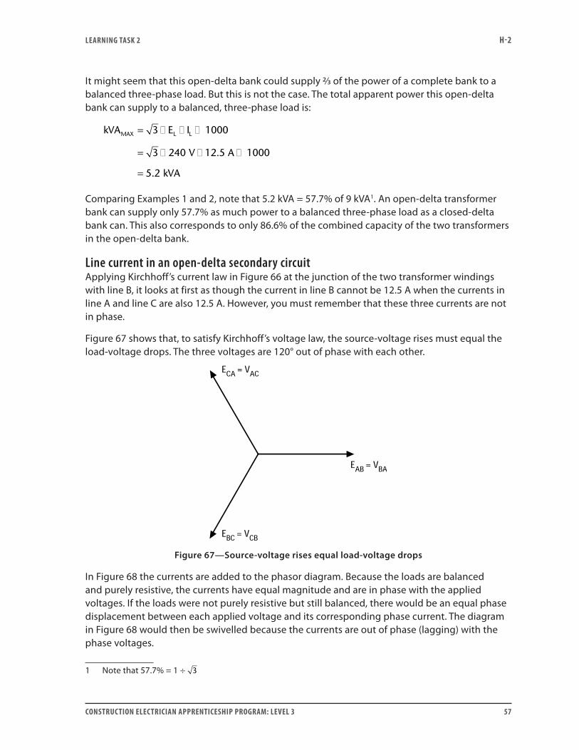
Figure 67 shows that, to satisfy Kirchhoff’s voltage law, the source-voltage rises must equal the load-voltage drops. The three voltages are 120° out of phase with each other.
Figure 67—Source-voltage rises equal load-voltage drops
In Figure 68 the currents are added to the phasor diagram. Because the loads are balanced and purely resistive, the currents have equal magnitude and are in phase with the applied voltages. If the loads were not purely resistive but still balanced, there would be an equal phase displacement between each applied voltage and its corresponding phase current. The diagram in Figure 68 would then be swivelled because the currents are out of phase (lagging) with the phase voltages.
1 Note that 57.7% = 1 ÷ 3
LEARNING TASk 2 H-2
58 CONSTRUCTION ELECTRICIAN APPRENTICESHIP PROGRAM: LEVEL 3
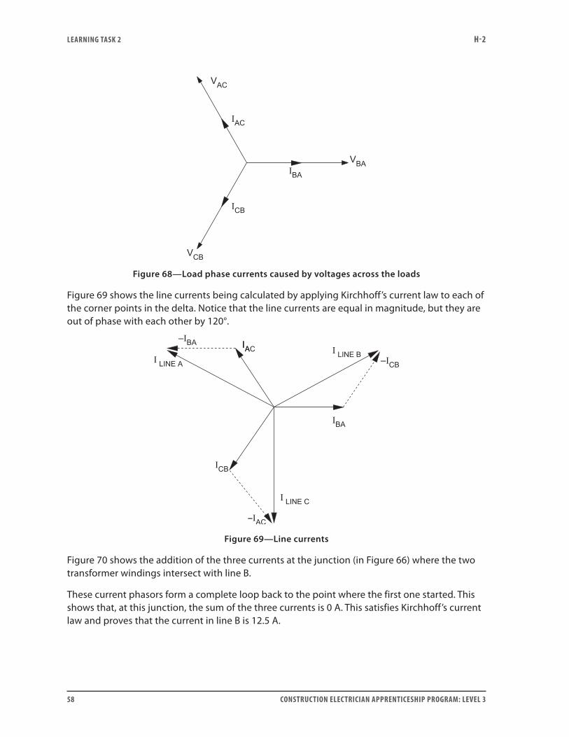
Figure 68—Load phase currents caused by voltages across the loads
Figure 69 shows the line currents being calculated by applying Kirchhoff’s current law to each of the corner points in the delta. Notice that the line currents are equal in magnitude, but they are out of phase with each other by 120°.
Figure 69—Line currents
Figure 70 shows the addition of the three currents at the junction (in Figure 66) where the two transformer windings intersect with line B.
These current phasors form a complete loop back to the point where the first one started. This shows that, at this junction, the sum of the three currents is 0 A. This satisfies Kirchhoff’s current law and proves that the current in line B is 12.5 A.
LEARNING TASk 2 H-2
CONSTRUCTION ELECTRICIAN APPRENTICESHIP PROGRAM: LEVEL 3 59
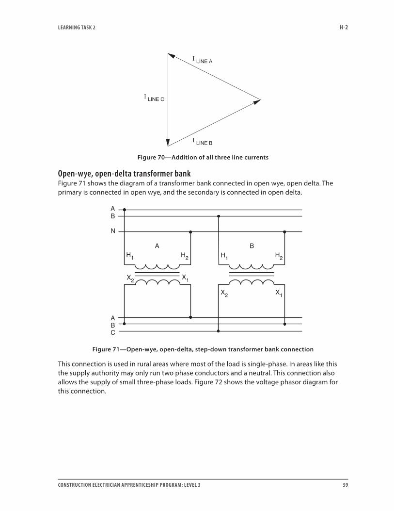
Figure 70—Addition of all three line currents
Open-wye, open-delta transformer bankFigure 71 shows the diagram of a transformer bank connected in open wye, open delta. The primary is connected in open wye, and the secondary is connected in open delta.
H1 H2
X1X2
H1 H2
X1X2
BA
N
CBA
AB
Figure 71—Open-wye, open-delta, step-down transformer bank connection
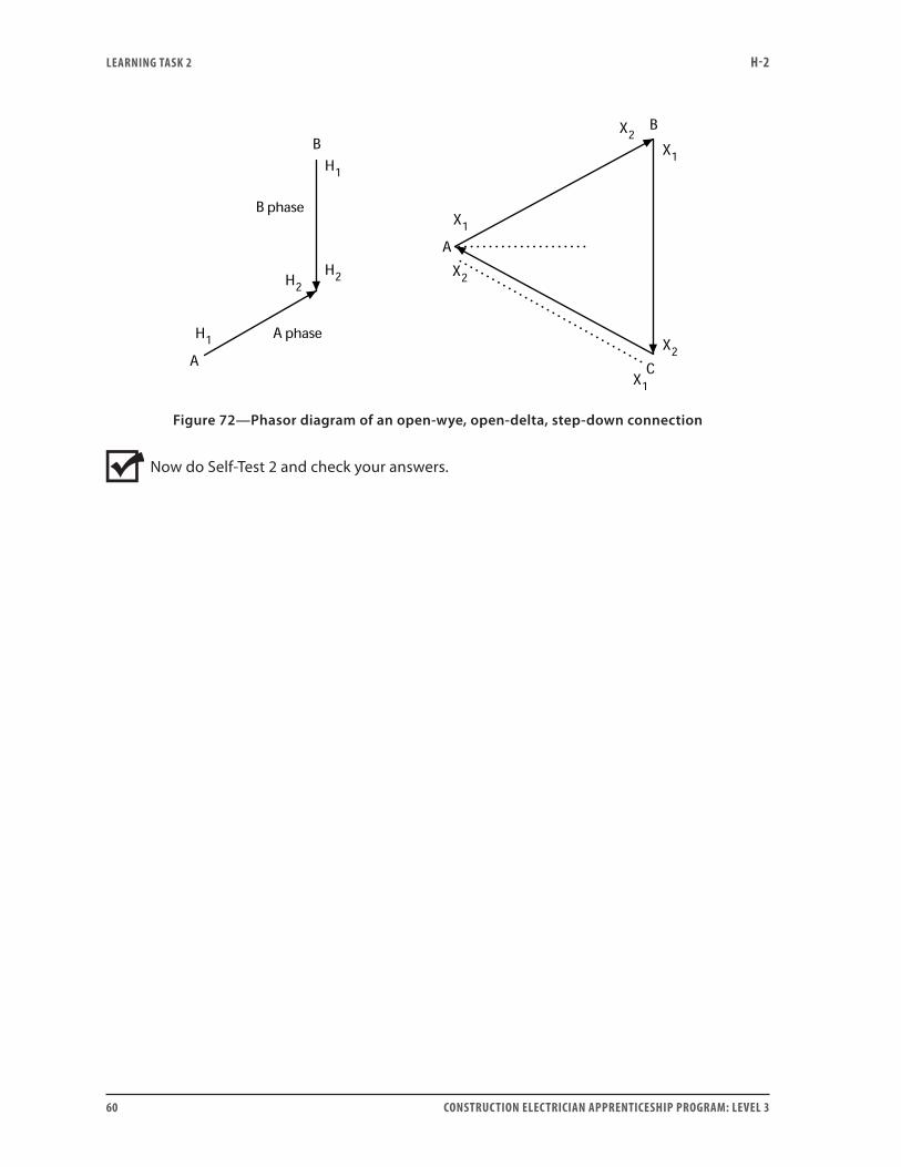
This connection is used in rural areas where most of the load is single-phase. In areas like this the supply authority may only run two phase conductors and a neutral. This connection also allows the supply of small three-phase loads. Figure 72 shows the voltage phasor diagram for this connection.
LEARNING TASk 2 H-2
60 CONSTRUCTION ELECTRICIAN APPRENTICESHIP PROGRAM: LEVEL 3
Figure 72—Phasor diagram of an open-wye, open-delta, step-down connection
Now do Self-Test 2 and check your answers.
LEARNING TASk 2 H-2
CONSTRUCTION ELECTRICIAN APPRENTICESHIP PROGRAM: LEVEL 3 61
Self-Test 2
1. How are the high-voltage and low-voltage terminals of a three-phase transformer normally marked?
2. What is meant by phase displacement between the high and low sides of a three-phase transformer?
3. What is meant by the term neutral point?
4. What is the standard phase displacement for wye-to-wye and delta-to-delta transformer connections?
5. What is the standard phase displacement for wye-to-delta and delta-to-wye transformer connections?
6. Which voltages do the phasors in voltage diagrams represent?
7. Which part of the phasor do the terminal markings H1 and X1 represent: the head or the tail?
8. In voltage diagrams for three-phase transformers, in what position is the high-side voltage VAN always drawn?
LEARNING TASk 2 H-2
62 CONSTRUCTION ELECTRICIAN APPRENTICESHIP PROGRAM: LEVEL 3
9. Why is the low-side phasor for any transformer always drawn parallel to the high-side phasor for the same transformer?
10. Where is the A-phase transformer normally located in a transformer bank when viewed from the high side?
11. Can an additive-polarity transformer be used in a bank with two subtractive-polarity transformers to make up a three-phase bank?
12. Can a subtractive-polarity transformer be used in a bank with two additive-polarity transformers to make up a three-phase bank?
13. Before connecting the load, what test should you perform on the secondary of a three-phase transformer bank with a wye-connected secondary?
14. If a voltmeter test on the secondary of a wye-to-wye connected transformer shows VAB = 208 V, VBC = 120 V and VCA = 120 V, what is indicated?
15. For a step-down application, would the primary lines connect to H1, H2 and H3 or to X1, X2 and X3?
LEARNING TASk 2 H-2
CONSTRUCTION ELECTRICIAN APPRENTICESHIP PROGRAM: LEVEL 3 63
Delta-delta connections16. What is the standard phase displacement for a delta-to-delta transformer connection?
17. On voltage diagrams for three-phase delta transformers, in what position is the high-side voltage phasor VAB always drawn?
18. Why is the low-side phasor for any transformer always drawn parallel to the high-side phasor for that transformer?
19. In a transformer bank, where is the A-phase transformer normally located when viewed from the high side?
20. Can an additive-polarity transformer be used with two subtractive-polarity transformers to make up a three-phase, delta-to-delta bank?
21. Can a subtractive-polarity transformer be used with two additive-polarity transformers to make up a three-phase, delta-to-delta bank?
22. What test must be performed on the secondary of a three-phase transformer bank with a delta-connected secondary?
23. The phase voltage on the delta-connected secondary of a three-phase transformer bank is 240 V. The test in Question 22 gives a reading of 73 V. Is it safe to remove the meter and install the final connection?
LEARNING TASk 2 H-2
64 CONSTRUCTION ELECTRICIAN APPRENTICESHIP PROGRAM: LEVEL 3
24. What is the most likely cause of the 73 V measurement in Question 23?
25. For a delta-to-delta, step-up application, do the primary lines connect to H1, H2 and H3, or to X1, X2 and X3?
Wye-delta connections26. What is the standard phase displacement for a wye-to-delta transformer connection? Which
side leads?
27. In voltage diagrams for three-phase transformers, at what position is the high-side voltage phasor VAB always drawn?
28. Why is the low-side phasor for any transformer always drawn parallel to the high-side phasor for the same transformer?
29. Where is the A-phase transformer normally located in a transformer bank viewed from the high side?
30. Can an additive-polarity transformer be used with two subtractive-polarity transformers to make up a three-phase, wye-to-delta bank?
LEARNING TASk 2 H-2
CONSTRUCTION ELECTRICIAN APPRENTICESHIP PROGRAM: LEVEL 3 65
31. Can a subtractive-polarity transformer be used with two additive-polarity transformers to make up a three-phase, wye-to-delta bank?
32. What test must be performed on the secondary of a three-phase transformer bank with a delta-connected secondary?
33. The phase voltage on the delta-connected secondary of a three-phase transformer bank is 480 V. The test in Question 32 gives a reading of 960 V. Is it safe to remove the meter and install the final connection?
34. If you use the same voltage diagram for a wye-to-delta, step-up application as for a wye-to-delta, step-down application, are you still conforming to the CSA standards for three-phase transformers?
Delta-wye connections35. What is the standard phase displacement for a delta-to-wye transformer connection? Which
side leads?
36. On voltage diagrams for three-phase, delta transformers, at what position is the high-side voltage phasor VAB drawn?
37. Why is the low-side phasor of a transformer always drawn parallel to the high-side phasor for that transformer?
LEARNING TASk 2 H-2
66 CONSTRUCTION ELECTRICIAN APPRENTICESHIP PROGRAM: LEVEL 3
38. In a transformer bank viewed from the high side, where is the A-phase transformer normally located?
39. Can an additive-polarity transformer be used with two subtractive-polarity transformers to make up a delta-to-wye, three-phase bank?
40. Can a subtractive-polarity transformer be used with two additive-polarity transformers to make up a delta-to-wye, three-phase bank?
41. What test must be performed on the secondary of a three-phase transformer bank with a wye-connected secondary?
42. What is the relationship between the primary line voltage and the primary transformer-winding voltage in a delta-to-wye, step-down transformer bank?
43. What is the relationship between the secondary line voltage and the secondary transformer-winding voltage in delta-to-wye, step-down transformer bank?
44. Can the same voltage diagram be used for a delta-to-wye, step-up application as for a delta-to-wye, step-down application and still conform to the CSA standards for three-phase transformers?
Special delta connections45. A three-phase, four-wire, delta-connected system is to be used for supplying both three-phase
motor loads and single-phase lighting loads. Where do you normally attach the ground?
LEARNING TASk 2 H-2
CONSTRUCTION ELECTRICIAN APPRENTICESHIP PROGRAM: LEVEL 3 67
46. If the line-to-line voltage on the delta system is 480 V, what will the voltages be between the following points?
a. line A to ground
b. line B to ground
c. line C to ground
47. Which phase does the CEC specify as the high leg?
48. Does the CEC permit this high leg to be in the compartment of a panelboard used to supply single-phase loads? Explain.
49. The transformer with the centre tap supplies all of the current to the single-phase load. The other two transformers supply only their share of the balanced three-phase load.
a. True
b. False
50. List three applications where an open-delta transformer connection is commonly used.
Go to the Answer Key at the end of the Learning Guide to check your answers.

68 CONSTRUCTION ELECTRICIAN APPRENTICESHIP PROGRAM: LEVEL 3
CONSTRUCTION ELECTRICIAN APPRENTICESHIP PROGRAM: LEVEL 3 69
Learning Task 3:
Calculate voltage, current and kVA values for three-phase transformer banksYou previously learned that for single-phase transformers:
VA VAIN OUT=
and
NN
EE
II
P
S
P
S
S
P
= =
where
NP = number of primary turns NS = number of secondary turns EP = primary voltage ES = secondary voltage IS = secondary current IP = primary current
Wye-to-wye transformer bank calculationsWhen a wye-to-wye transformer connection is used, the following applies:
• The line-to-line voltage ratio equals the individual single-phase-transformer voltage ratio.
• However, the primary and secondary line voltages are 3 times higher than the respective primary and secondary transformer winding voltages.
• This means the voltage ratings on the transformer windings need only be 57.7% of the line voltage.
• Because of this reduction in insulation stress, this transformer connection is often used to connect high-voltage (over 100 000 V) transmission systems with unequal voltages.
Since the transformer windings are in series with the lines, the line currents and their respective phase currents are equal. The primary-to-secondary current ratio equals the reciprocal of the primary-to-secondary voltage ratio. (Note: 3
1 is the reciprocal of 1
3.)
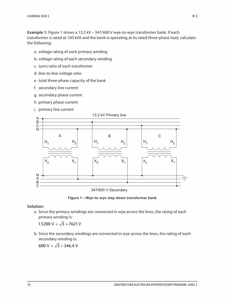
LEARNING TASk 3 H-2
70 CONSTRUCTION ELECTRICIAN APPRENTICESHIP PROGRAM: LEVEL 3
Example 1: Figure 1 shows a 13.2 kV – 347/600 V wye-to-wye transformer bank. If each transformer is rated at 100 kVA and the bank is operating at its rated three-phase load, calculate the following:
a. voltage rating of each primary winding
b. voltage rating of each secondary winding
c. turns ratio of each transformer
d. line-to-line voltage ratio
e. total three-phase capacity of the bank
f. secondary line current
g. secondary phase current
h. primary phase current
i. primary line current
Figure 1—Wye-to-wye step-down transformer bank
Solution:a. Since the primary windings are connected in wye across the lines, the rating of each
primary winding is:
13200 3 7621÷V V=
b. Since the secondary windings are connected in wye across the lines, the rating of each secondary winding is:
600 3 346 4÷V V= .
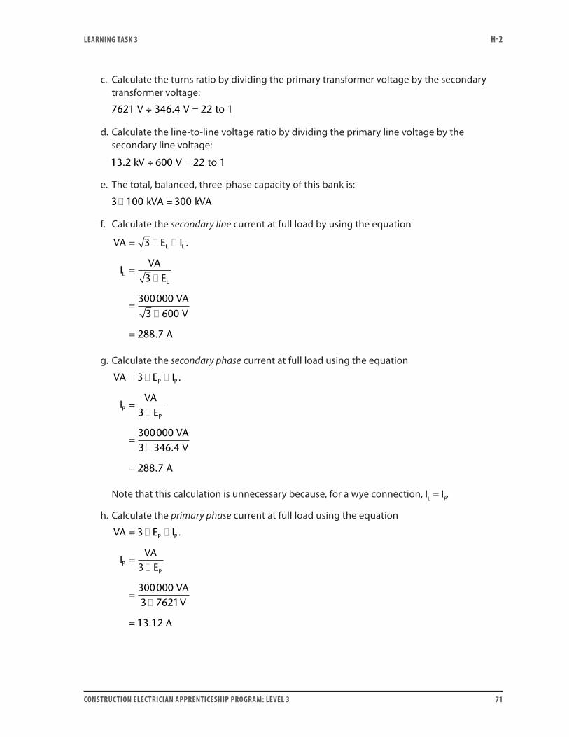
LEARNING TASk 3 H-2
CONSTRUCTION ELECTRICIAN APPRENTICESHIP PROGRAM: LEVEL 3 71
c. Calculate the turns ratio by dividing the primary transformer voltage by the secondary transformer voltage:
7621 V ÷ V to 1346 4 22. =
d. Calculate the line-to-line voltage ratio by dividing the primary line voltage by the secondary line voltage:
13.2 kV ÷ V to 1600 22=
e. The total, balanced, three-phase capacity of this bank is:
3 100 300� =kVA kVA
f. Calculate the secondary line current at full load by using the equation
VA E I
IVA
E
VAV
A
L L
LL
= � �
=�
=�
=
3
3
3000003 600
288 7
.
.
g. Calculate the secondary phase current at full load using the equation
VA E I
IVA
E
VAV
A
P P
PP
= � �
=�
=�
=
3
3
3000003 346 4
288 7
.
.
.
Note that this calculation is unnecessary because, for a wye connection, IL = IP.
h. Calculate the primary phase current at full load using the equation
VA E I
IVA
E
VAV
A
P P
PP
= � �
=�
=�
=
3
3
3000003 7621
13 12
.
.
LEARNING TASk 3 H-2
72 CONSTRUCTION ELECTRICIAN APPRENTICESHIP PROGRAM: LEVEL 3
i. The primary line current (13.12 A) equals the primary phase current because the phase windings are connected in wye.
Delta-to-delta transformer bank calculationsWhen a delta-to-delta transformer connection is used:
• The line-to-line voltage ratio equals the individual single-phase transformer voltage ratio.
• In this case each transformer winding is connected directly across the lines.
• Therefore, the primary and secondary line-to-line voltages equal the respective primary and secondary transformer winding voltages.
• Two phase windings connect to each line.
• This means that for balanced three-phase loads, the line current equals 3 times the phase (winding) current.
• The primary-to-secondary, line-to-line or phase-to-phase current ratio equals the reciprocal of the primary-to-secondary voltage ratio.
Example 2: Figure 2 shows a 4160 V – 480 V delta-to-delta transformer bank. If each transformer is rated at 200 kVA and the bank is operating at its rated three-phase capacity, calculate the following:
a. voltage rating of each primary winding
b. voltage rating of each secondary winding
c. turns ratio of each transformer
d. line-to-line voltage ratio
e. total three-phase capacity of the bank
f. secondary line current
g. secondary phase current
h. primary phase current
i. primary line current
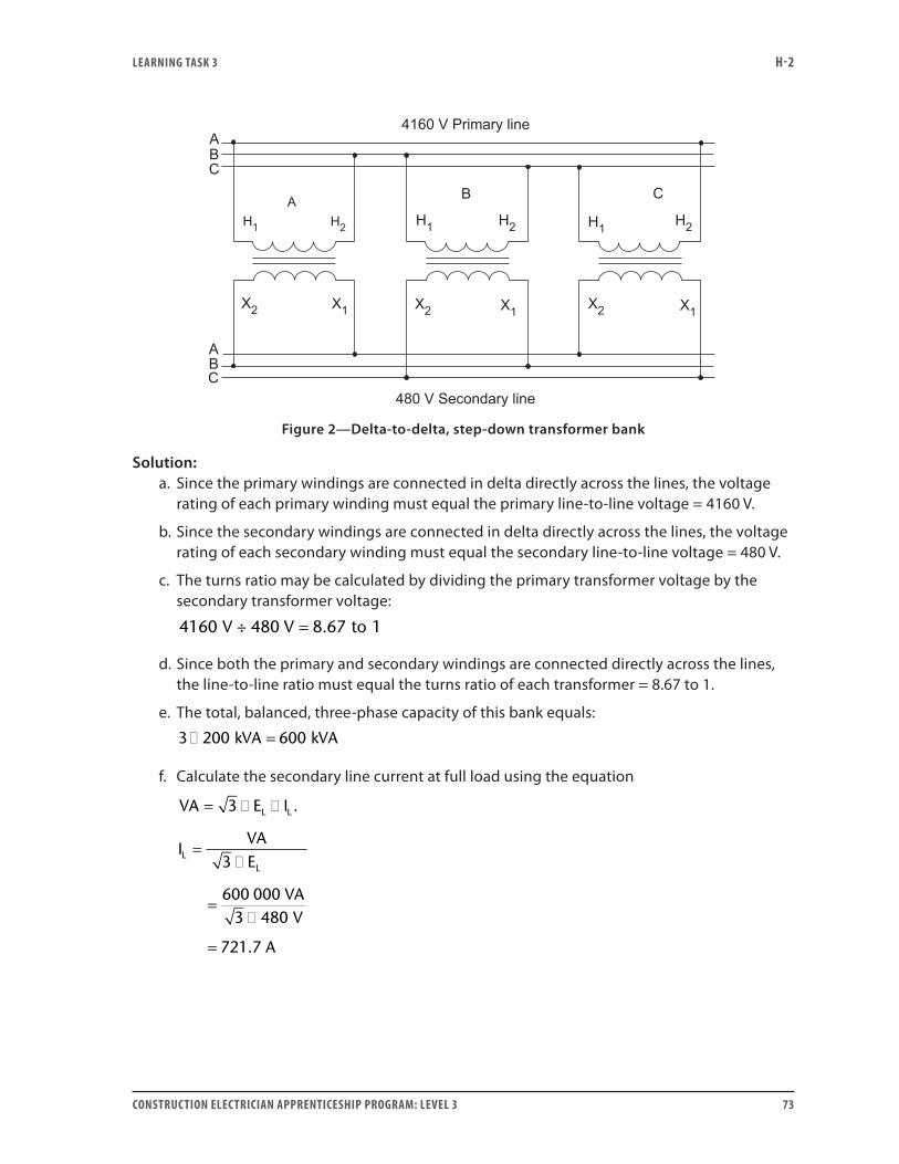
LEARNING TASk 3 H-2
CONSTRUCTION ELECTRICIAN APPRENTICESHIP PROGRAM: LEVEL 3 73
Figure 2—Delta-to-delta, step-down transformer bank
Solution:a. Since the primary windings are connected in delta directly across the lines, the voltage
rating of each primary winding must equal the primary line-to-line voltage = 4160 V.
b. Since the secondary windings are connected in delta directly across the lines, the voltage rating of each secondary winding must equal the secondary line-to-line voltage = 480 V.
c. The turns ratio may be calculated by dividing the primary transformer voltage by the secondary transformer voltage:
4160 8 67 1V ÷ 480 V to= .
d. Since both the primary and secondary windings are connected directly across the lines, the line-to-line ratio must equal the turns ratio of each transformer = 8.67 to 1.
e. The total, balanced, three-phase capacity of this bank equals:
3 200 600� =kVA kVA
f. Calculate the secondary line current at full load using the equation
VA E I
IVAE
L L
LL
= � �
=�
=�
=
3
3
480
.
600 000 VA3 V
721.7 A
LEARNING TASk 3 H-2
74 CONSTRUCTION ELECTRICIAN APPRENTICESHIP PROGRAM: LEVEL 3
g. Calculate the secondary phase current at full load using the equation
VA E I
IVA
E
VAV
A
P P
PP
= × ×
=×
=×
=
3
3
600 0003 480
416 7
.
.
h. Calculate the primary phase current at full load using the equation
VA E I
IPVA
E
A
P P
P
= × ×
=×
=×
=
3
3
6000003 4160
48 08
.
.
i. Calculate the primary line current at full load using the equation
VA E I
IVA
E
VAV
A
L L
LL
= × ×
=×
=×
=
3
3
6000003 4160
83 27
.
.
Wye-to-delta transformer bank calculationsWhen a wye-to-delta transformer connection is used:
• The line-to-line voltage ratio is 3 times the individual single-phase transformer-voltage ratio.
• The primary line-to-line voltage is also 3 times higher than the primary-winding voltage because it is wye connected.
• The secondary line-to-line voltage is equal to the secondary-winding voltage because it is delta connected.
• Since the primary windings are wye-connected, the primary phase current is equal to the primary line current.
• On the delta secondary, two windings connect to each line. This means that, for balanced
LEARNING TASk 3 H-2
CONSTRUCTION ELECTRICIAN APPRENTICESHIP PROGRAM: LEVEL 3 75
three-phase loads, the secondary line current is 3 times the secondary phase (winding) current.
• The primary-to-secondary, phase-to-phase current ratio is equal to the reciprocal of the single-phase, transformer-voltage ratio.
• The primary-to-secondary, line-to-line current ratio is equal to the reciprocal of the line-to-line voltage ratio.
Caution: If the neutral is connected on the primary side of this bank, the bank attempts to balance any load imbalance that might be present on the wye-connected primary bus. This could result in damage to the transformer or the neutral conductor.
Example 3: Figure 3 shows a 13.2 kV – 240 V wye-to-delta transformer bank. If each transformer is rated at 125 kVA and the bank is operating at its rated three-phase load, calculate the following:
a. voltage rating of each primary winding
b. voltage rating of each secondary winding
c. turns ratio of each transformer
d. line-to-line voltage ratio
e. total three-phase capacity of the bank
f. secondary line current
g. secondary phase current
h. primary phase current
i. primary line current
Solution:a. Since the primary windings are connected in wye across the lines, the rating of each
primary winding must be:
13 2 3 7 62. .÷kV kV=
b. The secondary windings are connected in delta directly across the lines. Therefore, the voltage rating of each secondary winding must equal the secondary line-to-line voltage = 240 V.
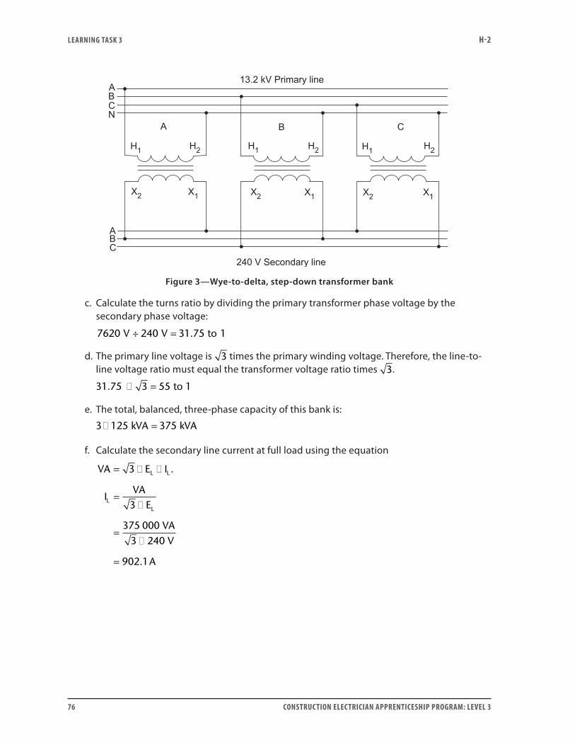
LEARNING TASk 3 H-2
76 CONSTRUCTION ELECTRICIAN APPRENTICESHIP PROGRAM: LEVEL 3
Figure 3—Wye-to-delta, step-down transformer bank
c. Calculate the turns ratio by dividing the primary transformer phase voltage by the secondary phase voltage:
7620 240 31 75 1÷V V to= .
d. The primary line voltage is 3 times the primary winding voltage. Therefore, the line-to-line voltage ratio must equal the transformer voltage ratio times 3.
31.75 3 to 1� = 55
e. The total, balanced, three-phase capacity of this bank is:
3 125 375� =kVA kVA
f. Calculate the secondary line current at full load using the equation
VA E I
I
L L
L
= � �
=�
=�
=
3
3
3 240
902 1
.
.
VAE
375 000 VAV
A
L
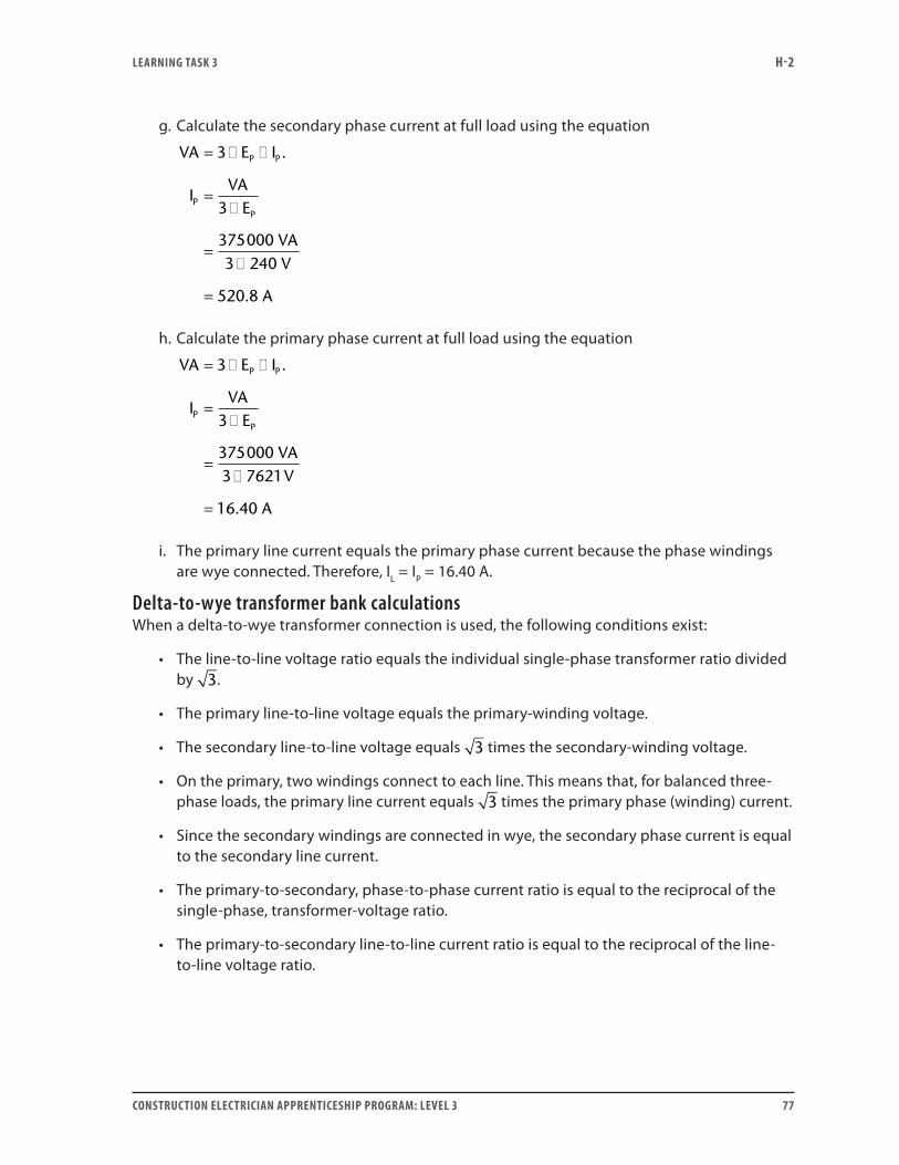
LEARNING TASk 3 H-2
CONSTRUCTION ELECTRICIAN APPRENTICESHIP PROGRAM: LEVEL 3 77
g. Calculate the secondary phase current at full load using the equation
VA E I
IVA
E
VAV
A
P P
PP
= � �
=�
=�
=
3
3
3750003 240
520 8
.
.
h. Calculate the primary phase current at full load using the equation
VA E I
IVA
E
VAV
A
P P
PP
= � �
=�
=�
=
3
3
3750003 7621
16 40
.
.
i. The primary line current equals the primary phase current because the phase windings are wye connected. Therefore, IL = IP = 16.40 A.
Delta-to-wye transformer bank calculationsWhen a delta-to-wye transformer connection is used, the following conditions exist:
• The line-to-line voltage ratio equals the individual single-phase transformer ratio divided by 3.
• The primary line-to-line voltage equals the primary-winding voltage.
• The secondary line-to-line voltage equals 3 times the secondary-winding voltage.
• On the primary, two windings connect to each line. This means that, for balanced three-phase loads, the primary line current equals 3 times the primary phase (winding) current.
• Since the secondary windings are connected in wye, the secondary phase current is equal to the secondary line current.
• The primary-to-secondary, phase-to-phase current ratio is equal to the reciprocal of the single-phase, transformer-voltage ratio.
• The primary-to-secondary line-to-line current ratio is equal to the reciprocal of the line-to-line voltage ratio.
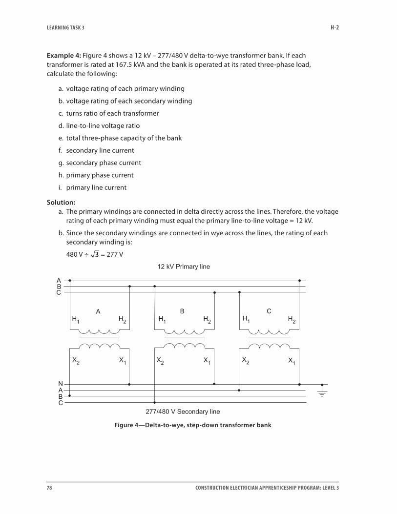
LEARNING TASk 3 H-2
78 CONSTRUCTION ELECTRICIAN APPRENTICESHIP PROGRAM: LEVEL 3
Example 4: Figure 4 shows a 12 kV – 277/480 V delta-to-wye transformer bank. If each transformer is rated at 167.5 kVA and the bank is operated at its rated three-phase load, calculate the following:
a. voltage rating of each primary winding
b. voltage rating of each secondary winding
c. turns ratio of each transformer
d. line-to-line voltage ratio
e. total three-phase capacity of the bank
f. secondary line current
g. secondary phase current
h. primary phase current
i. primary line current
Solution:a. The primary windings are connected in delta directly across the lines. Therefore, the voltage
rating of each primary winding must equal the primary line-to-line voltage = 12 kV.
b. Since the secondary windings are connected in wye across the lines, the rating of each secondary winding is:
480 V ÷ 3 = 277 V
Figure 4—Delta-to-wye, step-down transformer bank
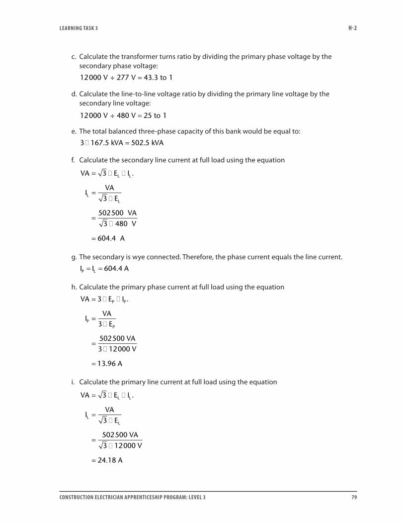
LEARNING TASk 3 H-2
CONSTRUCTION ELECTRICIAN APPRENTICESHIP PROGRAM: LEVEL 3 79
c. Calculate the transformer turns ratio by dividing the primary phase voltage by the secondary phase voltage:
12000 277 43 3 1÷V V to= .
d. Calculate the line-to-line voltage ratio by dividing the primary line voltage by the secondary line voltage:
12000 480 25 1÷V V to=
e. The total balanced three-phase capacity of this bank would be equal to:
3 167 5 502 5� =. .kVA kVA
f. Calculate the secondary line current at full load using the equation
VA E I
IVA
E
VAV
A
L L
LL
= � �
=�
=�
=
3
3
5025003 480
604 4
.
.
g. The secondary is wye connected. Therefore, the phase current equals the line current.
I I AP L= = 604 4.
h. Calculate the primary phase current at full load using the equation
VA E I
IVA
E
VAV
A
P P
PP
= � �
=�
=�
=
3
3
5025003 12000
13 96
.
.
i. Calculate the primary line current at full load using the equation
VA E I
IVA
E
VAV
A
L L
LL
= � �
=�
=�
=
3
3
5025003 12000
24 18
.
.
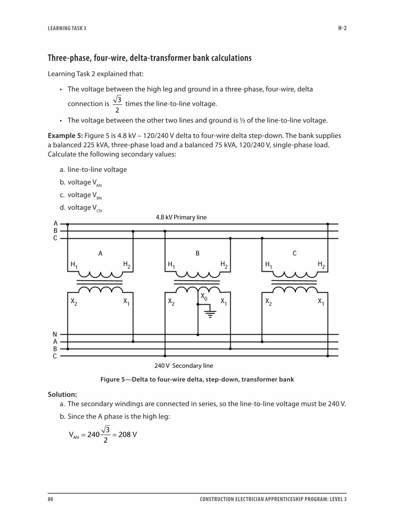
LEARNING TASk 3 H-2
80 CONSTRUCTION ELECTRICIAN APPRENTICESHIP PROGRAM: LEVEL 3
Three-phase, four-wire, delta-transformer bank calculations
Learning Task 2 explained that:
• The voltage between the high leg and ground in a three-phase, four-wire, delta
connection is 32
times the line-to-line voltage.
• The voltage between the other two lines and ground is 1/2 of the line-to-line voltage.
Example 5: Figure 5 is 4.8 kV – 120/240 V delta to four-wire delta step-down. The bank supplies a balanced 225 kVA, three-phase load and a balanced 75 kVA, 120/240 V, single-phase load. Calculate the following secondary values:
a. line-to-line voltage
b. voltage VAN
c. voltage VBN
d. voltage VCN
Figure 5—Delta to four-wire delta, step-down, transformer bank
Solution:a. The secondary windings are connected in series, so the line-to-line voltage must be 240 V.
b. Since the A phase is the high leg:
V VAN = =240
32
208
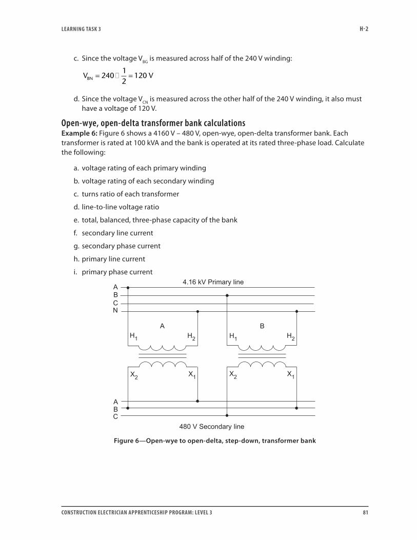
LEARNING TASk 3 H-2
CONSTRUCTION ELECTRICIAN APPRENTICESHIP PROGRAM: LEVEL 3 81
c. Since the voltage VBG is measured across half of the 240 V winding:
V VBN = � =240
12
120
d. Since the voltage VCN is measured across the other half of the 240 V winding, it also must have a voltage of 120 V.
Open-wye, open-delta transformer bank calculationsExample 6: Figure 6 shows a 4160 V – 480 V, open-wye, open-delta transformer bank. Each transformer is rated at 100 kVA and the bank is operated at its rated three-phase load. Calculate the following:
a. voltage rating of each primary winding
b. voltage rating of each secondary winding
c. turns ratio of each transformer
d. line-to-line voltage ratio
e. total, balanced, three-phase capacity of the bank
f. secondary line current
g. secondary phase current
h. primary line current
i. primary phase current
Figure 6—Open-wye to open-delta, step-down, transformer bank
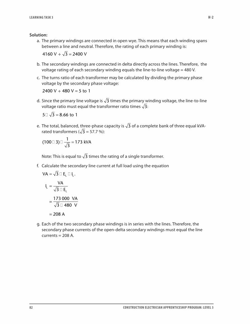
LEARNING TASk 3 H-2
82 CONSTRUCTION ELECTRICIAN APPRENTICESHIP PROGRAM: LEVEL 3
Solution:a. The primary windings are connected in open wye. This means that each winding spans
between a line and neutral. Therefore, the rating of each primary winding is:
4160 3 2400÷V V=
b. The secondary windings are connected in delta directly across the lines. Therefore, the voltage rating of each secondary winding equals the line-to-line voltage = 480 V.
c. The turns ratio of each transformer may be calculated by dividing the primary phase voltage by the secondary phase voltage:
2400 480 5 1÷V V to=
d. Since the primary line voltage is 3 times the primary winding voltage, the line-to-line voltage ratio must equal the transformer ratio times 3:
5 3 8 66 1� = . to
e. The total, balanced, three-phase capacity is 3 of a complete bank of three equal kVA-rated transformers ( 3 = 57.7 %):
( )100 3
13
173� � = kVA
Note: This is equal to 3 times the rating of a single transformer.
f. Calculate the secondary line current at full load using the equation
VA E I
IVA
E
VAV
A
L L
LL
= � �
=�
=�
=
3
3
173 0003 480
208
.
g. Each of the two secondary phase windings is in series with the lines. Therefore, the secondary phase currents of the open-delta secondary windings must equal the line currents = 208 A.
LEARNING TASk 3 H-2
CONSTRUCTION ELECTRICIAN APPRENTICESHIP PROGRAM: LEVEL 3 83
h. Calculate the primary line current at full load using the equation
VA E I
IVA
E
VAV
A
L L
LL
= � �
=�
=�
=
3
3
1730003 4160
24
.
i. Since the primary windings are connected in series with the primary lines, the line current equals the phase current (24 A).
Now do Self-Test 3 and check your answers.
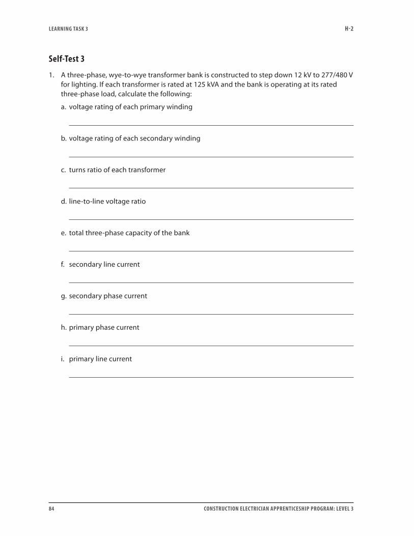
LEARNING TASk 3 H-2
84 CONSTRUCTION ELECTRICIAN APPRENTICESHIP PROGRAM: LEVEL 3
Self-Test 3
1. A three-phase, wye-to-wye transformer bank is constructed to step down 12 kV to 277/480 V for lighting. If each transformer is rated at 125 kVA and the bank is operating at its rated three-phase load, calculate the following:
a. voltage rating of each primary winding
b. voltage rating of each secondary winding
c. turns ratio of each transformer
d. line-to-line voltage ratio
e. total three-phase capacity of the bank
f. secondary line current
g. secondary phase current
h. primary phase current
i. primary line current
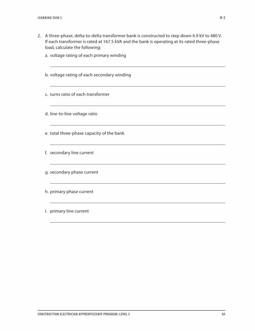
LEARNING TASk 3 H-2
CONSTRUCTION ELECTRICIAN APPRENTICESHIP PROGRAM: LEVEL 3 85
2. A three-phase, delta-to-delta transformer bank is constructed to step down 6.9 kV to 480 V. If each transformer is rated at 167.5 kVA and the bank is operating at its rated three-phase load, calculate the following:
a. voltage rating of each primary winding
b. voltage rating of each secondary winding
c. turns ratio of each transformer
d. line-to-line voltage ratio
e. total three-phase capacity of the bank
f. secondary line current
g. secondary phase current
h. primary phase current
i. primary line current
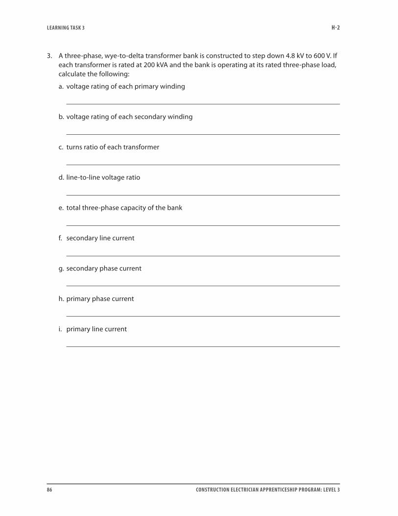
LEARNING TASk 3 H-2
86 CONSTRUCTION ELECTRICIAN APPRENTICESHIP PROGRAM: LEVEL 3
3. A three-phase, wye-to-delta transformer bank is constructed to step down 4.8 kV to 600 V. If each transformer is rated at 200 kVA and the bank is operating at its rated three-phase load, calculate the following:
a. voltage rating of each primary winding
b. voltage rating of each secondary winding
c. turns ratio of each transformer
d. line-to-line voltage ratio
e. total three-phase capacity of the bank
f. secondary line current
g. secondary phase current
h. primary phase current
i. primary line current
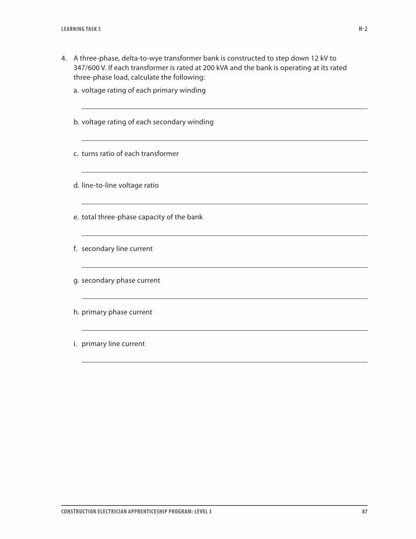
LEARNING TASk 3 H-2
CONSTRUCTION ELECTRICIAN APPRENTICESHIP PROGRAM: LEVEL 3 87
4. A three-phase, delta-to-wye transformer bank is constructed to step down 12 kV to 347/600 V. If each transformer is rated at 200 kVA and the bank is operating at its rated three-phase load, calculate the following:
a. voltage rating of each primary winding
b. voltage rating of each secondary winding
c. turns ratio of each transformer
d. line-to-line voltage ratio
e. total three-phase capacity of the bank
f. secondary line current
g. secondary phase current
h. primary phase current
i. primary line current
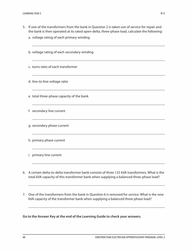
LEARNING TASk 3 H-2
88 CONSTRUCTION ELECTRICIAN APPRENTICESHIP PROGRAM: LEVEL 3
5. If one of the transformers from the bank in Question 2 is taken out of service for repair and the bank is then operated at its rated open-delta, three-phase load, calculate the following:
a. voltage rating of each primary winding
b. voltage rating of each secondary winding
c. turns ratio of each transformer
d. line-to-line voltage ratio
e. total three-phase capacity of the bank
f. secondary line current
g. secondary phase current
h. primary phase current
i. primary line current
6. A certain delta-to-delta transformer bank consists of three 125 kVA transformers. What is the total kVA capacity of this transformer bank when supplying a balanced three-phase load?
7. One of the transformers from the bank in Question 6 is removed for service. What is the new kVA capacity of the transformer bank when supplying a balanced three-phase load?
Go to the Answer Key at the end of the Learning Guide to check your answers.
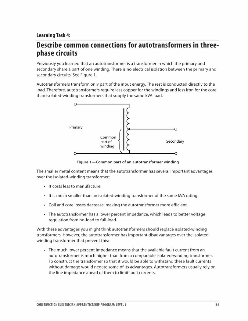
CONSTRUCTION ELECTRICIAN APPRENTICESHIP PROGRAM: LEVEL 3 89
Learning Task 4:
Describe common connections for autotransformers in three-phase circuitsPreviously you learned that an autotransformer is a transformer in which the primary and secondary share a part of one winding. There is no electrical isolation between the primary and secondary circuits. See Figure 1.
Autotransformers transform only part of the input energy. The rest is conducted directly to the load. Therefore, autotransformers require less copper for the windings and less iron for the core than isolated-winding transformers that supply the same kVA load.
Primary
SecondaryCommonpart ofwinding
Figure 1—Common part of an autotransformer winding
The smaller metal content means that the autotransformer has several important advantages over the isolated-winding transformer:
• It costs less to manufacture.
• It is much smaller than an isolated-winding transformer of the same kVA rating.
• Coil and core losses decrease, making the autotransformer more efficient.
• The autotransformer has a lower percent impedance, which leads to better voltage regulation from no-load to full-load.
With these advantages you might think autotransformers should replace isolated-winding transformers. However, the autotransformer has important disadvantages over the isolated-winding transformer that prevent this:
• The much lower percent impedance means that the available fault current from an autotransformer is much higher than from a comparable isolated-winding transformer. To construct the transformer so that it would be able to withstand these fault currents without damage would negate some of its advantages. Autotransformers usually rely on the line impedance ahead of them to limit fault currents.
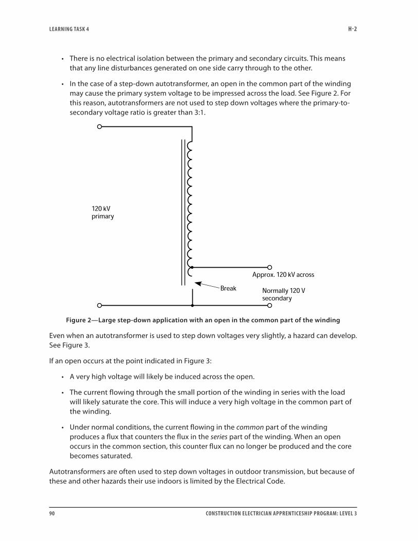
LEARNING TASk 4 H-2
90 CONSTRUCTION ELECTRICIAN APPRENTICESHIP PROGRAM: LEVEL 3
• There is no electrical isolation between the primary and secondary circuits. This means that any line disturbances generated on one side carry through to the other.
• In the case of a step-down autotransformer, an open in the common part of the winding may cause the primary system voltage to be impressed across the load. See Figure 2. For this reason, autotransformers are not used to step down voltages where the primary-to-secondary voltage ratio is greater than 3:1.
Figure 2—Large step-down application with an open in the common part of the winding
Even when an autotransformer is used to step down voltages very slightly, a hazard can develop. See Figure 3.
If an open occurs at the point indicated in Figure 3:
• A very high voltage will likely be induced across the open.
• The current flowing through the small portion of the winding in series with the load will likely saturate the core. This will induce a very high voltage in the common part of the winding.
• Under normal conditions, the current flowing in the common part of the winding produces a flux that counters the flux in the series part of the winding. When an open occurs in the common section, this counter flux can no longer be produced and the core becomes saturated.
Autotransformers are often used to step down voltages in outdoor transmission, but because of these and other hazards their use indoors is limited by the Electrical Code.
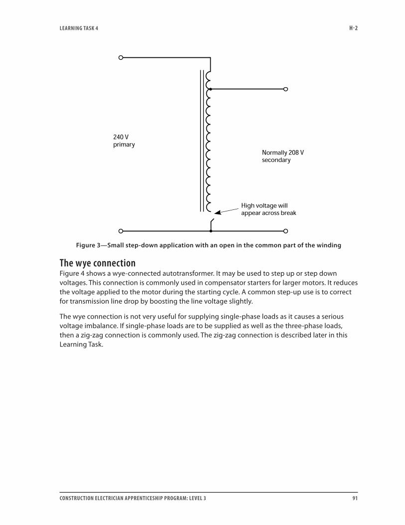
LEARNING TASk 4 H-2
CONSTRUCTION ELECTRICIAN APPRENTICESHIP PROGRAM: LEVEL 3 91
Figure 3—Small step-down application with an open in the common part of the winding
The wye connectionFigure 4 shows a wye-connected autotransformer. It may be used to step up or step down voltages. This connection is commonly used in compensator starters for larger motors. It reduces the voltage applied to the motor during the starting cycle. A common step-up use is to correct for transmission line drop by boosting the line voltage slightly.
The wye connection is not very useful for supplying single-phase loads as it causes a serious voltage imbalance. If single-phase loads are to be supplied as well as the three-phase loads, then a zig-zag connection is commonly used. The zig-zag connection is described later in this Learning Task.
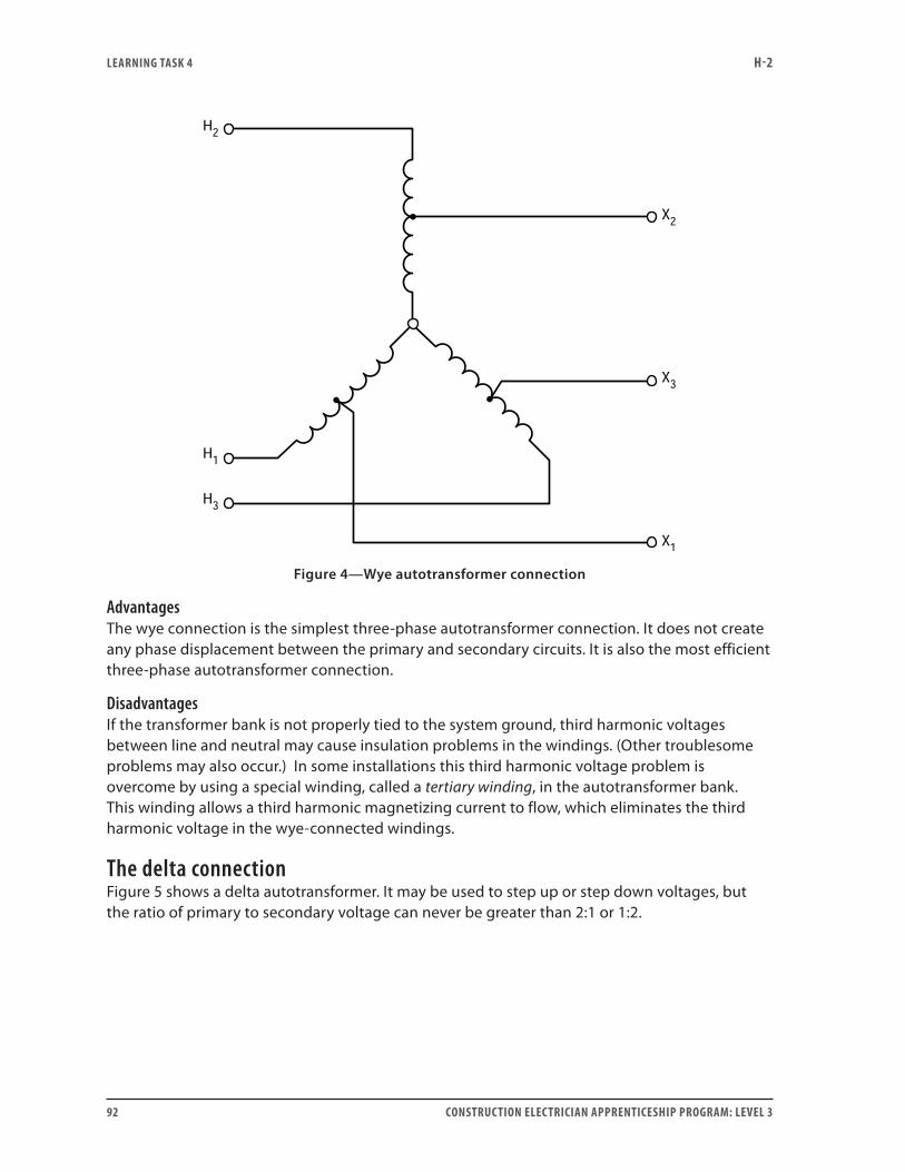
LEARNING TASk 4 H-2
92 CONSTRUCTION ELECTRICIAN APPRENTICESHIP PROGRAM: LEVEL 3
Figure 4—Wye autotransformer connection
AdvantagesThe wye connection is the simplest three-phase autotransformer connection. It does not create any phase displacement between the primary and secondary circuits. It is also the most efficient three-phase autotransformer connection.
DisadvantagesIf the transformer bank is not properly tied to the system ground, third harmonic voltages between line and neutral may cause insulation problems in the windings. (Other troublesome problems may also occur.) In some installations this third harmonic voltage problem is overcome by using a special winding, called a tertiary winding, in the autotransformer bank. This winding allows a third harmonic magnetizing current to flow, which eliminates the third harmonic voltage in the wye-connected windings.
The delta connectionFigure 5 shows a delta autotransformer. It may be used to step up or step down voltages, but the ratio of primary to secondary voltage can never be greater than 2:1 or 1:2.
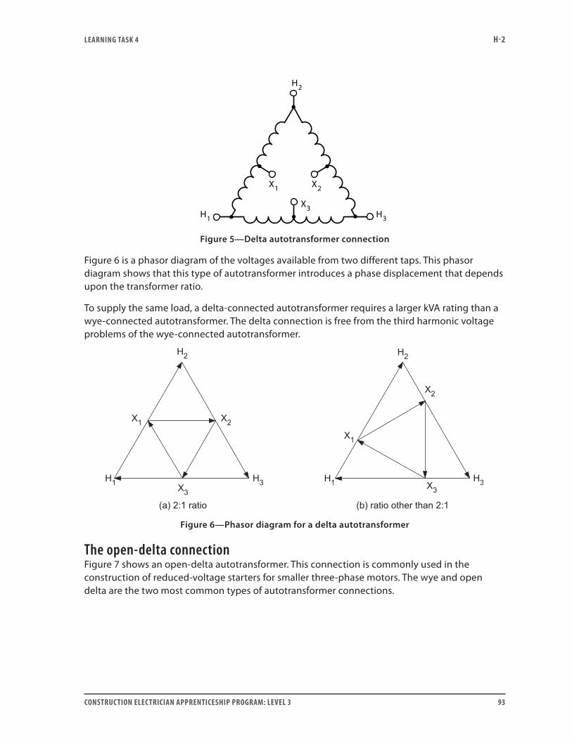
LEARNING TASk 4 H-2
CONSTRUCTION ELECTRICIAN APPRENTICESHIP PROGRAM: LEVEL 3 93
X1 X2
X3H3H1
H2
Figure 5—Delta autotransformer connection
Figure 6 is a phasor diagram of the voltages available from two different taps. This phasor diagram shows that this type of autotransformer introduces a phase displacement that depends upon the transformer ratio.
To supply the same load, a delta-connected autotransformer requires a larger kVA rating than a wye-connected autotransformer. The delta connection is free from the third harmonic voltage problems of the wye-connected autotransformer.
Figure 6—Phasor diagram for a delta autotransformer
The open-delta connectionFigure 7 shows an open-delta autotransformer. This connection is commonly used in the construction of reduced-voltage starters for smaller three-phase motors. The wye and open delta are the two most common types of autotransformer connections.
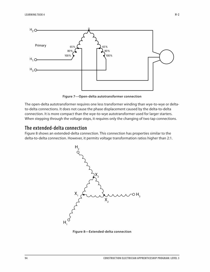
LEARNING TASk 4 H-2
94 CONSTRUCTION ELECTRICIAN APPRENTICESHIP PROGRAM: LEVEL 3
Figure 7—Open-delta autotransformer connection
The open-delta autotransformer requires one less transformer winding than wye-to-wye or delta-to-delta connections. It does not cause the phase displacement caused by the delta-to-delta connection. It is more compact than the wye-to-wye autotransformer used for larger starters. When stepping through the voltage steps, it requires only the changing of two tap connections.
The extended-delta connectionFigure 8 shows an extended-delta connection. This connection has properties similar to the delta-to-delta connection. However, it permits voltage transformation ratios higher than 2:1.
H2
H1
X1
X2
H3
X2
Figure 8—Extended-delta connection
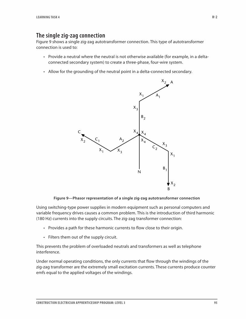
LEARNING TASk 4 H-2
CONSTRUCTION ELECTRICIAN APPRENTICESHIP PROGRAM: LEVEL 3 95
The single zig-zag connectionFigure 9 shows a single zig-zag autotransformer connection. This type of autotransformer connection is used to:
• Provide a neutral where the neutral is not otherwise available (for example, in a delta-connected secondary system) to create a three-phase, four-wire system.
• Allow for the grounding of the neutral point in a delta-connected secondary.
X2
X2
X2
X1
X1
X1
X3
X3
C1
C2
B2
B1
A1
A2X3
X4 X4
X4
C
A
N
B
Figure 9—Phasor representation of a single zig-zag autotransformer connection
Using switching-type power supplies in modern equipment such as personal computers and variable frequency drives causes a common problem. This is the introduction of third harmonic (180 Hz) currents into the supply circuits. The zig-zag transformer connection:
• Provides a path for these harmonic currents to flow close to their origin.
• Filters them out of the supply circuit.
This prevents the problem of overloaded neutrals and transformers as well as telephone interference.
Under normal operating conditions, the only currents that flow through the windings of the zig-zag transformer are the extremely small excitation currents. These currents produce counter emfs equal to the applied voltages of the windings.
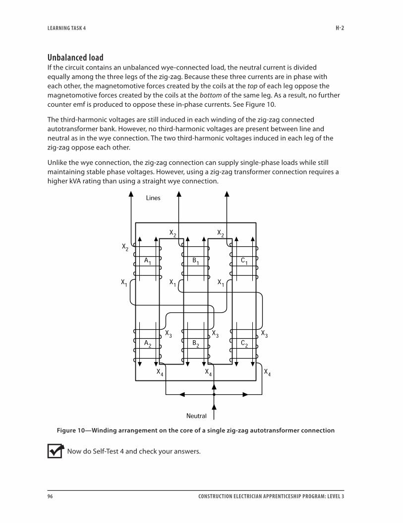
LEARNING TASk 4 H-2
96 CONSTRUCTION ELECTRICIAN APPRENTICESHIP PROGRAM: LEVEL 3
Unbalanced loadIf the circuit contains an unbalanced wye-connected load, the neutral current is divided equally among the three legs of the zig-zag. Because these three currents are in phase with each other, the magnetomotive forces created by the coils at the top of each leg oppose the magnetomotive forces created by the coils at the bottom of the same leg. As a result, no further counter emf is produced to oppose these in-phase currents. See Figure 10.
The third-harmonic voltages are still induced in each winding of the zig-zag connected autotransformer bank. However, no third-harmonic voltages are present between line and neutral as in the wye connection. The two third-harmonic voltages induced in each leg of the zig-zag oppose each other.
Unlike the wye connection, the zig-zag connection can supply single-phase loads while still maintaining stable phase voltages. However, using a zig-zag transformer connection requires a higher kVA rating than using a straight wye connection.
Figure 10—Winding arrangement on the core of a single zig-zag autotransformer connection
Now do Self-Test 4 and check your answers.
LEARNING TASk 4 H-2
CONSTRUCTION ELECTRICIAN APPRENTICESHIP PROGRAM: LEVEL 3 97
Self-Test 4
1. State the two major disadvantages the autotransformer has compared with the standard isolated-winding transformer.
2. Which one of the following creates a phase displacement between the primary and secondary voltages?
a. the wye connection
b. the closed-delta connection
c. the open-delta connection
3. What is the purpose of the tertiary winding included in some wye-connected autotransformer banks?
4. What is the maximum transformer voltage ratio available from a standard delta-connected autotransformer?
5. What advantage does the open-delta have over the wye-connected compensator type of motor starter?
6. What advantage does the extended-delta autotransformer have over the standard-delta autotransformer?
LEARNING TASk 4 H-2
98 CONSTRUCTION ELECTRICIAN APPRENTICESHIP PROGRAM: LEVEL 3
7. State four advantages the autotransformer has over the standard isolated-winding transformer.
8. Why are autotransformers not normally used to step down voltages in ratios of more than 2:1 or 3:1?
9. Currents are caused by third-harmonic voltages induced into systems by switching power supplies. Which autotransformer connection is commonly used to filter them out?
10. Which autotransformer connection would likely be used to achieve a desired phase displacement between the primary and secondary systems?
Go to the Answer Key at the end of the Learning Guide to check your answers.
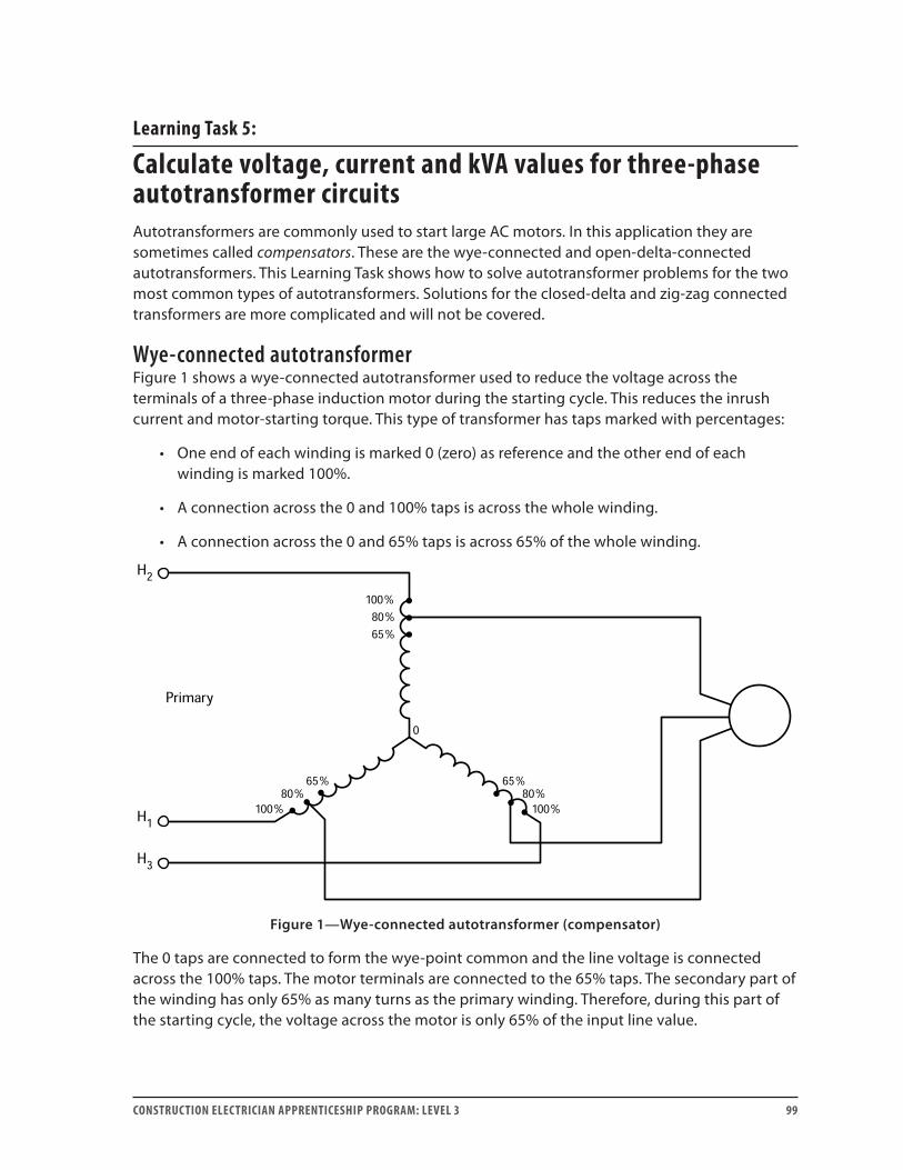
CONSTRUCTION ELECTRICIAN APPRENTICESHIP PROGRAM: LEVEL 3 99
Learning Task 5:
Calculate voltage, current and kVA values for three-phase autotransformer circuitsAutotransformers are commonly used to start large AC motors. In this application they are sometimes called compensators. These are the wye-connected and open-delta-connected autotransformers. This Learning Task shows how to solve autotransformer problems for the two most common types of autotransformers. Solutions for the closed-delta and zig-zag connected transformers are more complicated and will not be covered.
Wye-connected autotransformerFigure 1 shows a wye-connected autotransformer used to reduce the voltage across the terminals of a three-phase induction motor during the starting cycle. This reduces the inrush current and motor-starting torque. This type of transformer has taps marked with percentages:
• One end of each winding is marked 0 (zero) as reference and the other end of each winding is marked 100%.
• A connection across the 0 and 100% taps is across the whole winding.
• A connection across the 0 and 65% taps is across 65% of the whole winding.
Figure 1—Wye-connected autotransformer (compensator)
The 0 taps are connected to form the wye-point common and the line voltage is connected across the 100% taps. The motor terminals are connected to the 65% taps. The secondary part of the winding has only 65% as many turns as the primary winding. Therefore, during this part of the starting cycle, the voltage across the motor is only 65% of the input line value.
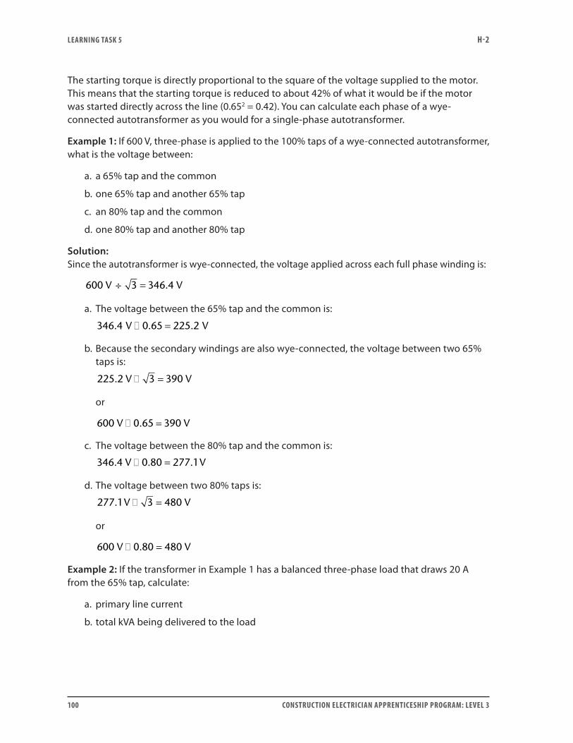
LEARNING TASk 5 H-2
100 CONSTRUCTION ELECTRICIAN APPRENTICESHIP PROGRAM: LEVEL 3
The starting torque is directly proportional to the square of the voltage supplied to the motor. This means that the starting torque is reduced to about 42% of what it would be if the motor was started directly across the line (0.652 = 0.42). You can calculate each phase of a wye-connected autotransformer as you would for a single-phase autotransformer.
Example 1: If 600 V, three-phase is applied to the 100% taps of a wye-connected autotransformer, what is the voltage between:
a. a 65% tap and the common
b. one 65% tap and another 65% tap
c. an 80% tap and the common
d. one 80% tap and another 80% tap
Solution:Since the autotransformer is wye-connected, the voltage applied across each full phase winding is:
600 3 346 4V V÷ = .
a. The voltage between the 65% tap and the common is:
346 4 0 65 225 2. . .V V� =
b. Because the secondary windings are also wye-connected, the voltage between two 65% taps is:
225 2 3 390. V V� =
or
600 0 65 390V V� =.
c. The voltage between the 80% tap and the common is:
346 4 0 80 277 1. . .V V� =
d. The voltage between two 80% taps is:
277 1 3 480. V V� =
or
600 V 0.80 480 V� =
Example 2: If the transformer in Example 1 has a balanced three-phase load that draws 20 A from the 65% tap, calculate:
a. primary line current
b. total kVA being delivered to the load
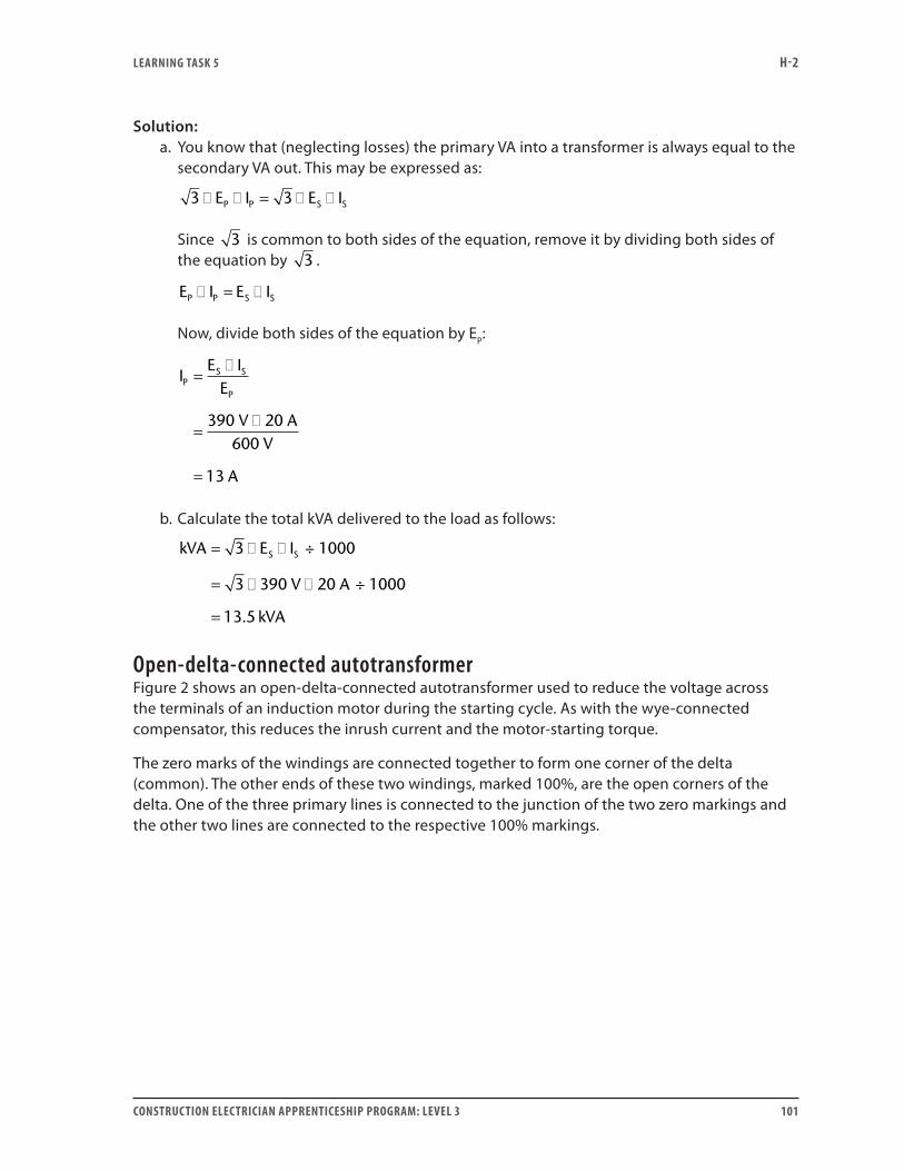
LEARNING TASk 5 H-2
CONSTRUCTION ELECTRICIAN APPRENTICESHIP PROGRAM: LEVEL 3 101
Solution:a. You know that (neglecting losses) the primary VA into a transformer is always equal to the
secondary VA out. This may be expressed as:
3 3� � = � �E I E IP P S S
Since 3 is common to both sides of the equation, remove it by dividing both sides of the equation by 3 .
E I E IP P S S� = �
Now, divide both sides of the equation by EP:
IE I
E
V AV
A
PS S
P
=�
=�
=
390 20600
13
b. Calculate the total kVA delivered to the load as follows:
kVA E I
V A
kVA
S S= � �
= � �
=
3 1000
3 390 20 1000
13 5
÷
÷
.
Open-delta-connected autotransformerFigure 2 shows an open-delta-connected autotransformer used to reduce the voltage across the terminals of an induction motor during the starting cycle. As with the wye-connected compensator, this reduces the inrush current and the motor-starting torque.
The zero marks of the windings are connected together to form one corner of the delta (common). The other ends of these two windings, marked 100%, are the open corners of the delta. One of the three primary lines is connected to the junction of the two zero markings and the other two lines are connected to the respective 100% markings.
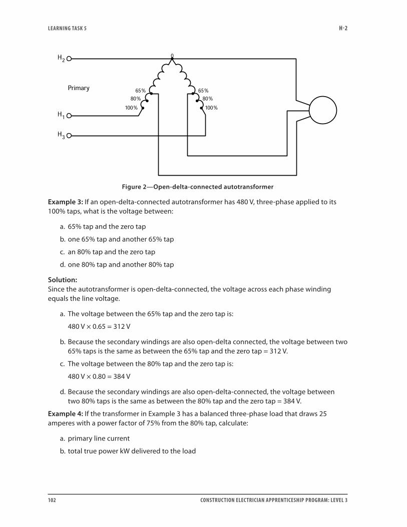
LEARNING TASk 5 H-2
102 CONSTRUCTION ELECTRICIAN APPRENTICESHIP PROGRAM: LEVEL 3
Figure 2—Open-delta-connected autotransformer
Example 3: If an open-delta-connected autotransformer has 480 V, three-phase applied to its 100% taps, what is the voltage between:
a. 65% tap and the zero tap
b. one 65% tap and another 65% tap
c. an 80% tap and the zero tap
d. one 80% tap and another 80% tap
Solution:Since the autotransformer is open-delta-connected, the voltage across each phase winding equals the line voltage.
a. The voltage between the 65% tap and the zero tap is:
480 V × 0.65 = 312 V
b. Because the secondary windings are also open-delta connected, the voltage between two 65% taps is the same as between the 65% tap and the zero tap = 312 V.
c. The voltage between the 80% tap and the zero tap is:
480 V × 0.80 = 384 V
d. Because the secondary windings are also open-delta-connected, the voltage between two 80% taps is the same as between the 80% tap and the zero tap = 384 V.
Example 4: If the transformer in Example 3 has a balanced three-phase load that draws 25 amperes with a power factor of 75% from the 80% tap, calculate:
a. primary line current
b. total true power kW delivered to the load
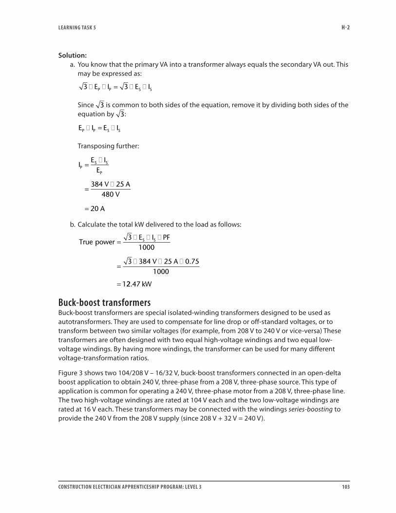
LEARNING TASk 5 H-2
CONSTRUCTION ELECTRICIAN APPRENTICESHIP PROGRAM: LEVEL 3 103
Solution:a. You know that the primary VA into a transformer always equals the secondary VA out. This
may be expressed as:
3 E I 3 E IP P S S� � = � �
Since 3 is common to both sides of the equation, remove it by dividing both sides of the equation by 3:
E I E IP P S S� = �
Transposing further:
IE I
E
V AV
A
PS S
P
=�
=�
=
384 25480
20
b. Calculate the total kW delivered to the load as follows:
True powerE I PF
V A
S S=� � �
=� � �
=
31000
3 384 25 0 751000
1
.
22 47. kW
Buck-boost transformersBuck-boost transformers are special isolated-winding transformers designed to be used as autotransformers. They are used to compensate for line drop or off-standard voltages, or to transform between two similar voltages (for example, from 208 V to 240 V or vice-versa) These transformers are often designed with two equal high-voltage windings and two equal low-voltage windings. By having more windings, the transformer can be used for many different voltage-transformation ratios.
Figure 3 shows two 104/208 V – 16/32 V, buck-boost transformers connected in an open-delta boost application to obtain 240 V, three-phase from a 208 V, three-phase source. This type of application is common for operating a 240 V, three-phase motor from a 208 V, three-phase line. The two high-voltage windings are rated at 104 V each and the two low-voltage windings are rated at 16 V each. These transformers may be connected with the windings series-boosting to provide the 240 V from the 208 V supply (since 208 V + 32 V = 240 V).
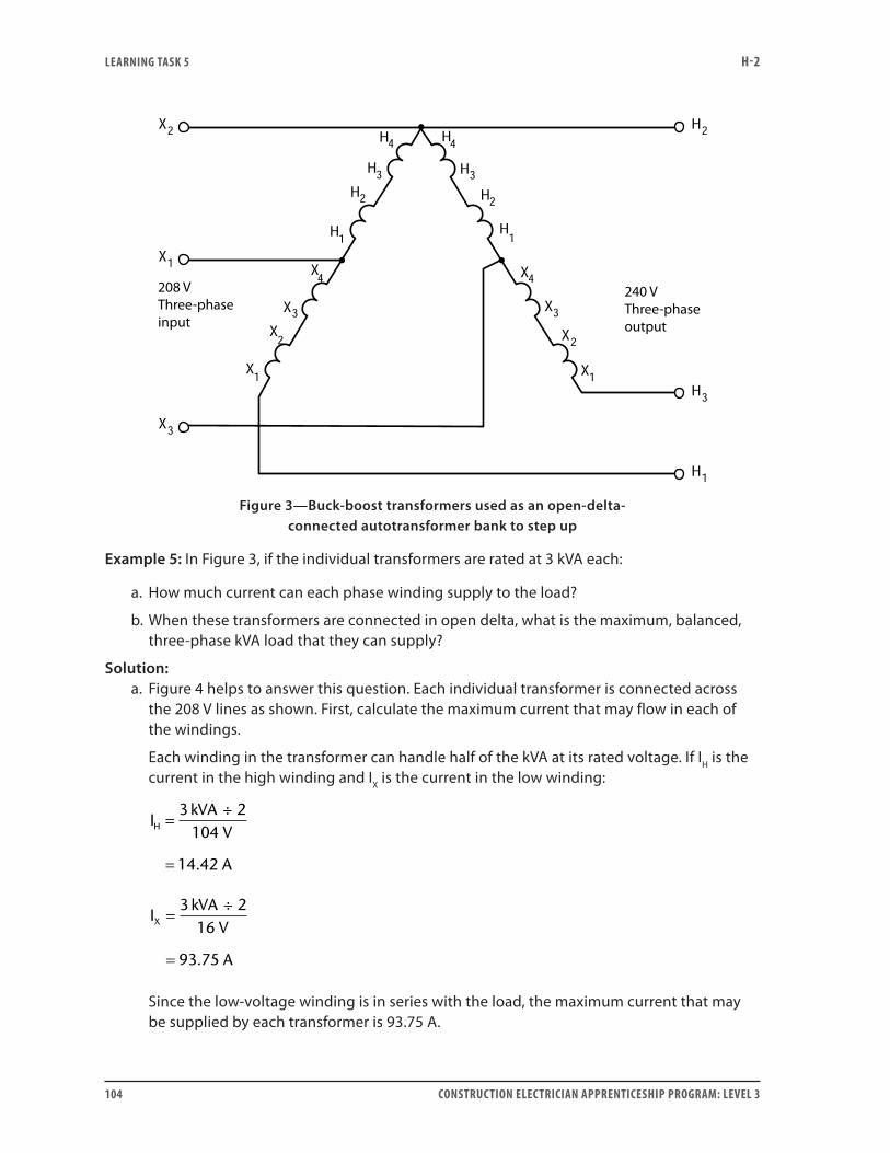
LEARNING TASk 5 H-2
104 CONSTRUCTION ELECTRICIAN APPRENTICESHIP PROGRAM: LEVEL 3
Figure 3—Buck-boost transformers used as an open-delta- connected autotransformer bank to step up
Example 5: In Figure 3, if the individual transformers are rated at 3 kVA each:
a. How much current can each phase winding supply to the load?
b. When these transformers are connected in open delta, what is the maximum, balanced, three-phase kVA load that they can supply?
Solution:a. Figure 4 helps to answer this question. Each individual transformer is connected across
the 208 V lines as shown. First, calculate the maximum current that may flow in each of the windings.
Each winding in the transformer can handle half of the kVA at its rated voltage. If IH is the current in the high winding and IX is the current in the low winding:
IkVA
V
A
H =
=
3 2104
14 42
÷
.
IkVA
V
A
X =
=
3 216
93 75
÷
.
Since the low-voltage winding is in series with the load, the maximum current that may be supplied by each transformer is 93.75 A.
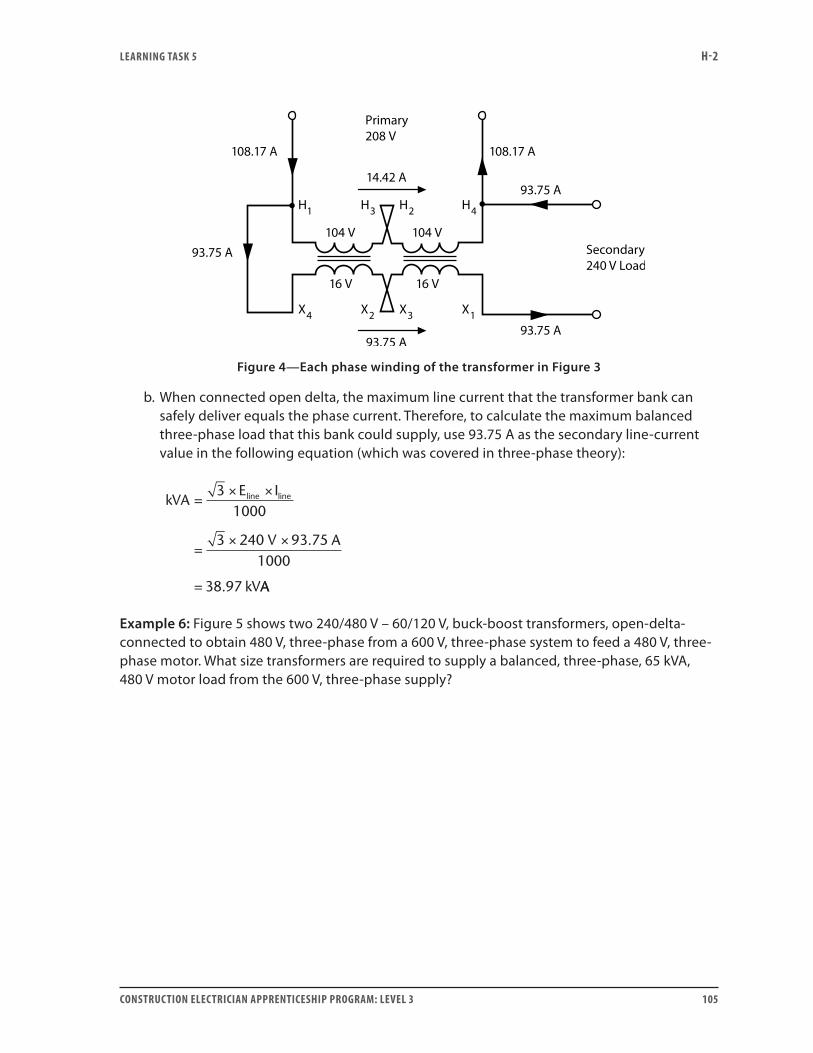
LEARNING TASk 5 H-2
CONSTRUCTION ELECTRICIAN APPRENTICESHIP PROGRAM: LEVEL 3 105
Figure 4—Each phase winding of the transformer in Figure 3
b. When connected open delta, the maximum line current that the transformer bank can safely deliver equals the phase current. Therefore, to calculate the maximum balanced three-phase load that this bank could supply, use 93.75 A as the secondary line-current value in the following equation (which was covered in three-phase theory):
kVAE I
V A
kV
line line=× ×
=× ×
=
31000
3 240 93 751000
38 97
.
. AA
Example 6: Figure 5 shows two 240/480 V – 60/120 V, buck-boost transformers, open-delta-connected to obtain 480 V, three-phase from a 600 V, three-phase system to feed a 480 V, three-phase motor. What size transformers are required to supply a balanced, three-phase, 65 kVA, 480 V motor load from the 600 V, three-phase supply?
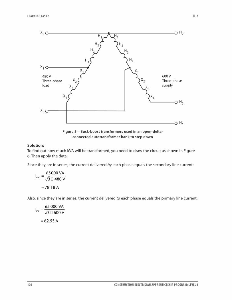
LEARNING TASk 5 H-2
106 CONSTRUCTION ELECTRICIAN APPRENTICESHIP PROGRAM: LEVEL 3
480 VThree-phaseload
600 VThree-phasesupply
Figure 5—Buck-boost transformers used in an open-delta- connected autotransformer bank to step down
Solution:To find out how much kVA will be transformed, you need to draw the circuit as shown in Figure 6. Then apply the data.
Since they are in series, the current delivered by each phase equals the secondary line current:
IVA
V
A
load =�
=
650003 480
78 18.
Also, since they are in series, the current delivered to each phase equals the primary line current:
IVA
V
A
line =�
=
65 0003 600
62 55.
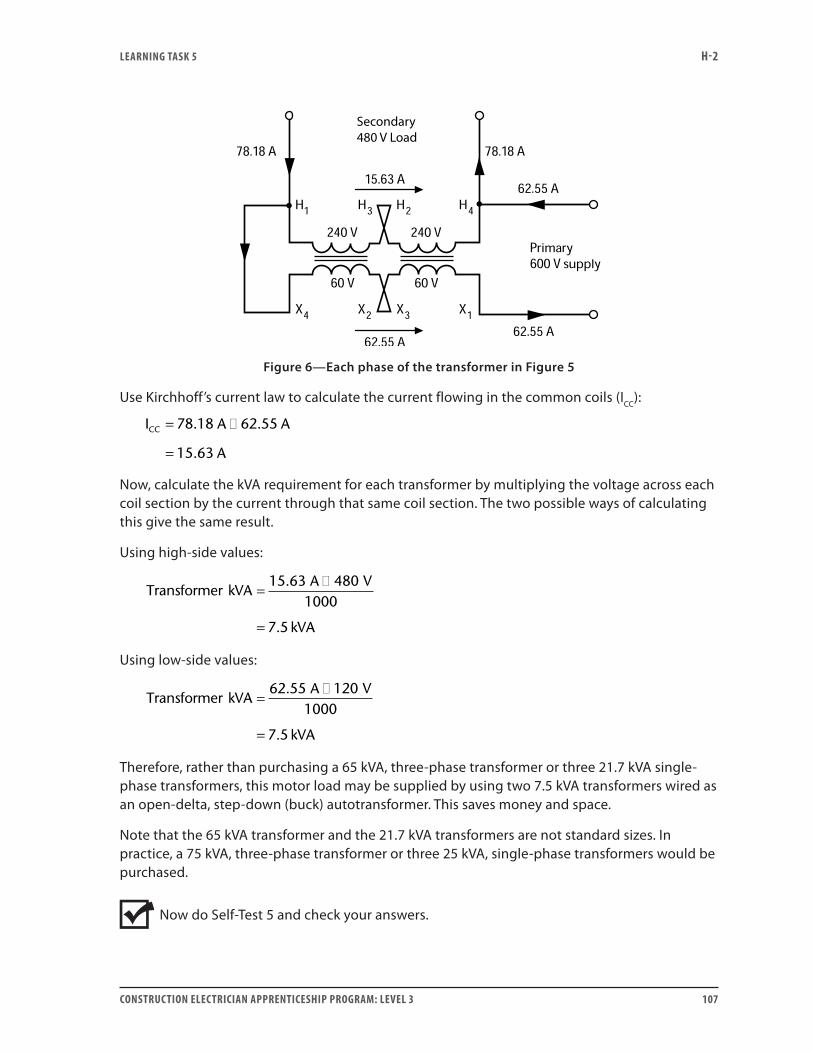
LEARNING TASk 5 H-2
CONSTRUCTION ELECTRICIAN APPRENTICESHIP PROGRAM: LEVEL 3 107
Figure 6—Each phase of the transformer in Figure 5
Use Kirchhoff’s current law to calculate the current flowing in the common coils (ICC):
I A A
A
CC = �
=
78 18 62 55
15 63
. .
.
Now, calculate the kVA requirement for each transformer by multiplying the voltage across each coil section by the current through that same coil section. The two possible ways of calculating this give the same result.
Using high-side values:
Transformer kVAA V
kVA
=�
=
15 63 4801000
7 5
.
.
Using low-side values:
Transformer kVAA V
kVA
=�
=
62 55 1201000
7 5
.
.
Therefore, rather than purchasing a 65 kVA, three-phase transformer or three 21.7 kVA single-phase transformers, this motor load may be supplied by using two 7.5 kVA transformers wired as an open-delta, step-down (buck) autotransformer. This saves money and space.
Note that the 65 kVA transformer and the 21.7 kVA transformers are not standard sizes. In practice, a 75 kVA, three-phase transformer or three 25 kVA, single-phase transformers would be purchased.
Now do Self-Test 5 and check your answers.
LEARNING TASk 5 H-2
108 CONSTRUCTION ELECTRICIAN APPRENTICESHIP PROGRAM: LEVEL 3
Self-Test 5
1. If a wye-connected autotransformer has 208 V, three-phase applied to its 100% taps, what is the voltage between:
a. a 65% tap and the zero tap
b. one 65% tap and another 65% tap
c. an 80% tap and the zero tap
d. one 80% tap and another 80% tap
2. Suppose the transformer in Question 1 has a balanced, three-phase load that draws 15 A with a power factor of 80% from the 65% tap. What is the primary line current and what is the total kW being delivered to the load?
3. If an open-delta-connected autotransformer has 240 V, three-phase applied to its 100% taps, what is the voltage between:
a. a 65% tap and the zero tap
b. one 65% tap and another 65% tap
c. an 80% tap and the zero tap
d. one 80% tap and another 80% tap
LEARNING TASk 5 H-2
CONSTRUCTION ELECTRICIAN APPRENTICESHIP PROGRAM: LEVEL 3 109
4. If the transformer in Question 3 has a balanced, three-phase load that draws 30 A with a power factor of 75% from the 80% tap, what is the primary line current and what is the total kW being delivered to the load?
5. Two 240/480 V – 60/120 V, 15 kVA, buck-boost transformers are to be connected open delta to supply a balanced 600 V, three-phase load from a 480 V, three-phase supply. What is the maximum three-phase kVA that these transformers can supply to the balanced load without overloading?
6. Two 104/208 V – 16/32 V, buck-boost transformers are to be open-delta-connected to supply a balanced, three-phase motor load of 65 kVA. The supply to the transformers is 240 V, three-phase, and the motor load requires an operating voltage of 208 V, three-phase. What is the minimum size of each transformer that you can use for this open-delta bank?
Go to the Answer Key at the end of the Learning Guide to check your answers.

110 CONSTRUCTION ELECTRICIAN APPRENTICESHIP PROGRAM: LEVEL 3
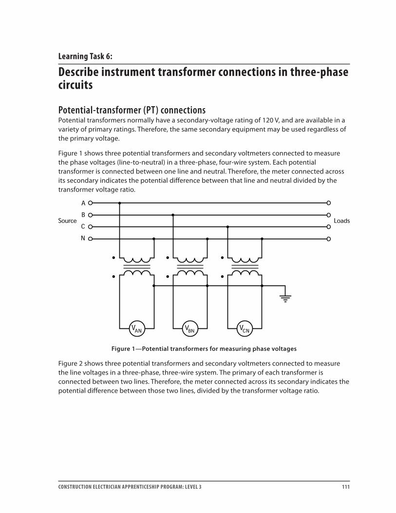
CONSTRUCTION ELECTRICIAN APPRENTICESHIP PROGRAM: LEVEL 3 111
Learning Task 6:
Describe instrument transformer connections in three-phase circuits
Potential-transformer (PT) connectionsPotential transformers normally have a secondary-voltage rating of 120 V, and are available in a variety of primary ratings. Therefore, the same secondary equipment may be used regardless of the primary voltage.
Figure 1 shows three potential transformers and secondary voltmeters connected to measure the phase voltages (line-to-neutral) in a three-phase, four-wire system. Each potential transformer is connected between one line and neutral. Therefore, the meter connected across its secondary indicates the potential difference between that line and neutral divided by the transformer voltage ratio.
Figure 1—Potential transformers for measuring phase voltages
Figure 2 shows three potential transformers and secondary voltmeters connected to measure the line voltages in a three-phase, three-wire system. The primary of each transformer is connected between two lines. Therefore, the meter connected across its secondary indicates the potential difference between those two lines, divided by the transformer voltage ratio.
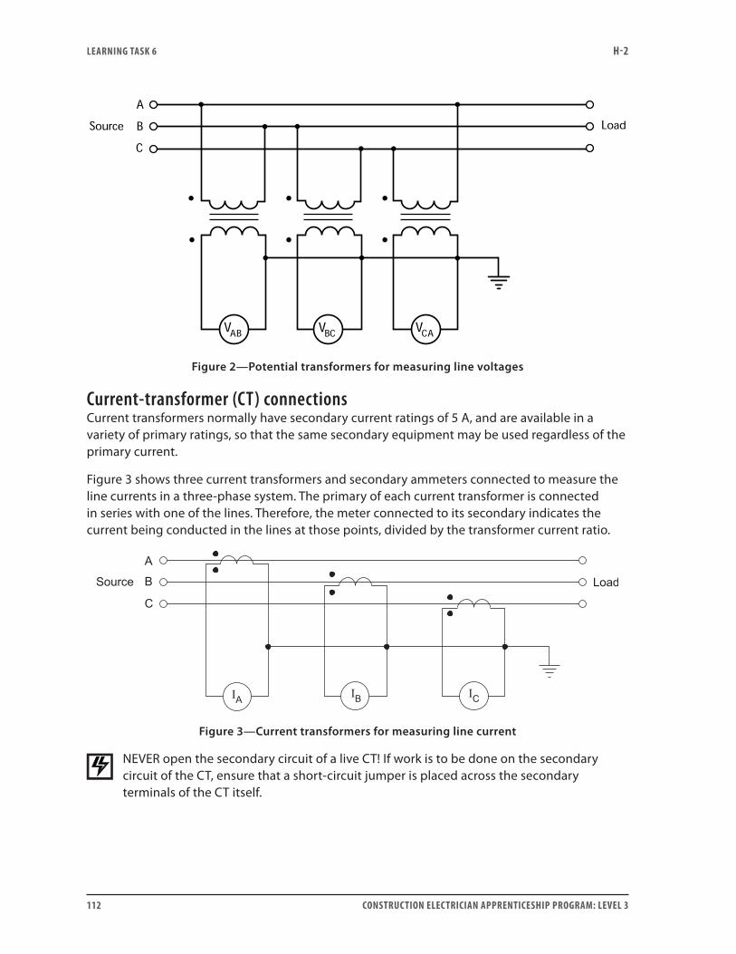
LEARNING TASk 6 H-2
112 CONSTRUCTION ELECTRICIAN APPRENTICESHIP PROGRAM: LEVEL 3
Figure 2—Potential transformers for measuring line voltages
Current-transformer (CT) connectionsCurrent transformers normally have secondary current ratings of 5 A, and are available in a variety of primary ratings, so that the same secondary equipment may be used regardless of the primary current.
Figure 3 shows three current transformers and secondary ammeters connected to measure the line currents in a three-phase system. The primary of each current transformer is connected in series with one of the lines. Therefore, the meter connected to its secondary indicates the current being conducted in the lines at those points, divided by the transformer current ratio.
Figure 3—Current transformers for measuring line current
NEVER open the secondary circuit of a live CT! If work is to be done on the secondary circuit of the CT, ensure that a short-circuit jumper is placed across the secondary terminals of the CT itself.
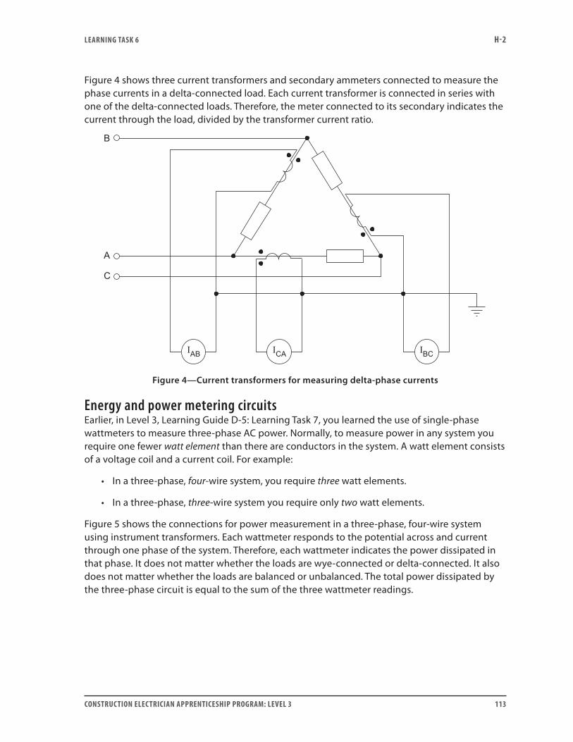
LEARNING TASk 6 H-2
CONSTRUCTION ELECTRICIAN APPRENTICESHIP PROGRAM: LEVEL 3 113
Figure 4 shows three current transformers and secondary ammeters connected to measure the phase currents in a delta-connected load. Each current transformer is connected in series with one of the delta-connected loads. Therefore, the meter connected to its secondary indicates the current through the load, divided by the transformer current ratio.
Figure 4—Current transformers for measuring delta-phase currents
Energy and power metering circuitsEarlier, in Level 3, Learning Guide D-5: Learning Task 7, you learned the use of single-phase wattmeters to measure three-phase AC power. Normally, to measure power in any system you require one fewer watt element than there are conductors in the system. A watt element consists of a voltage coil and a current coil. For example:
• In a three-phase, four-wire system, you require three watt elements.
• In a three-phase, three-wire system you require only two watt elements.
Figure 5 shows the connections for power measurement in a three-phase, four-wire system using instrument transformers. Each wattmeter responds to the potential across and current through one phase of the system. Therefore, each wattmeter indicates the power dissipated in that phase. It does not matter whether the loads are wye-connected or delta-connected. It also does not matter whether the loads are balanced or unbalanced. The total power dissipated by the three-phase circuit is equal to the sum of the three wattmeter readings.
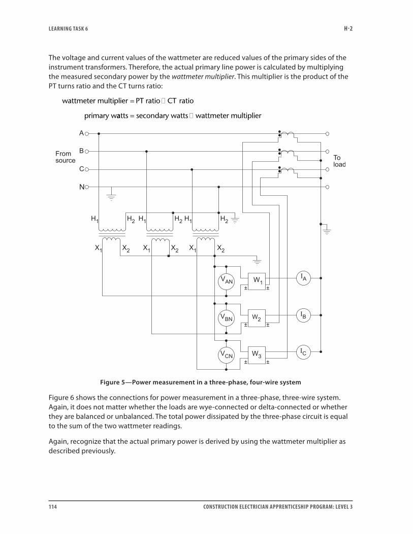
LEARNING TASk 6 H-2
114 CONSTRUCTION ELECTRICIAN APPRENTICESHIP PROGRAM: LEVEL 3
The voltage and current values of the wattmeter are reduced values of the primary sides of the instrument transformers. Therefore, the actual primary line power is calculated by multiplying the measured secondary power by the wattmeter multiplier. This multiplier is the product of the PT turns ratio and the CT turns ratio:
wattmeter multiplier PT ratio ratio
primary w
= � CT
aatts secondary watts wattmeter multiplier= �
Figure 5—Power measurement in a three-phase, four-wire system
Figure 6 shows the connections for power measurement in a three-phase, three-wire system. Again, it does not matter whether the loads are wye-connected or delta-connected or whether they are balanced or unbalanced. The total power dissipated by the three-phase circuit is equal to the sum of the two wattmeter readings.
Again, recognize that the actual primary power is derived by using the wattmeter multiplier as described previously.
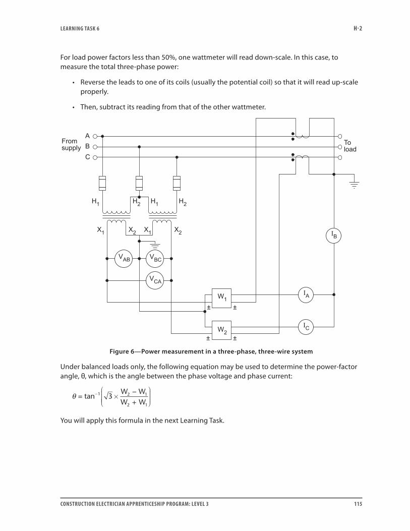
LEARNING TASk 6 H-2
CONSTRUCTION ELECTRICIAN APPRENTICESHIP PROGRAM: LEVEL 3 115
For load power factors less than 50%, one wattmeter will read down-scale. In this case, to measure the total three-phase power:
• Reverse the leads to one of its coils (usually the potential coil) so that it will read up-scale properly.
• Then, subtract its reading from that of the other wattmeter.
Figure 6—Power measurement in a three-phase, three-wire system
Under balanced loads only, the following equation may be used to determine the power-factor angle, θ, which is the angle between the phase voltage and phase current:
θ = ×−+
−tan 1 2 1
2 1
3W WW W
You will apply this formula in the next Learning Task.
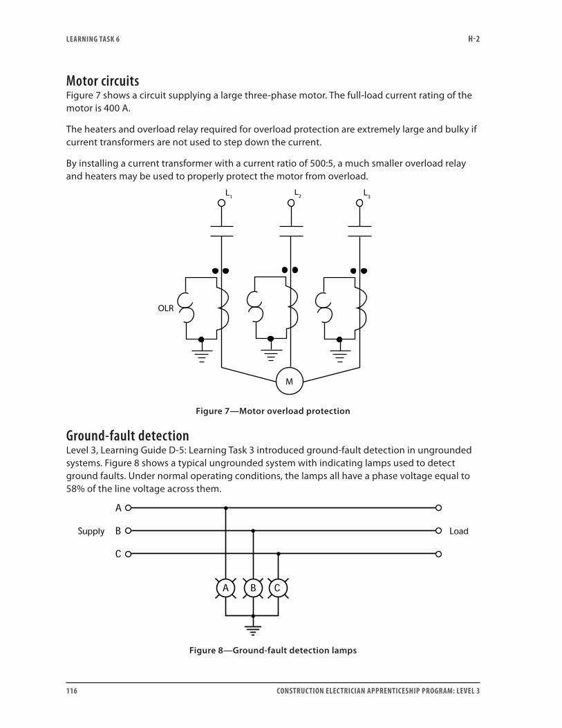
LEARNING TASk 6 H-2
116 CONSTRUCTION ELECTRICIAN APPRENTICESHIP PROGRAM: LEVEL 3
Motor circuitsFigure 7 shows a circuit supplying a large three-phase motor. The full-load current rating of the motor is 400 A.
The heaters and overload relay required for overload protection are extremely large and bulky if current transformers are not used to step down the current.
By installing a current transformer with a current ratio of 500:5, a much smaller overload relay and heaters may be used to properly protect the motor from overload.
M
OLR
L3L2L1
Figure 7—Motor overload protection
Ground-fault detectionLevel 3, Learning Guide D-5: Learning Task 3 introduced ground-fault detection in ungrounded systems. Figure 8 shows a typical ungrounded system with indicating lamps used to detect ground faults. Under normal operating conditions, the lamps all have a phase voltage equal to 58% of the line voltage across them.
Figure 8—Ground-fault detection lamps
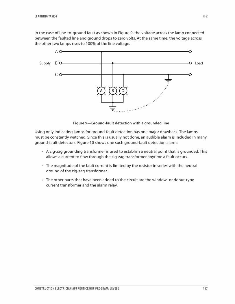
LEARNING TASk 6 H-2
CONSTRUCTION ELECTRICIAN APPRENTICESHIP PROGRAM: LEVEL 3 117
In the case of line-to-ground fault as shown in Figure 9, the voltage across the lamp connected between the faulted line and ground drops to zero volts. At the same time, the voltage across the other two lamps rises to 100% of the line voltage.
Figure 9—Ground-fault detection with a grounded line
Using only indicating lamps for ground-fault detection has one major drawback. The lamps must be constantly watched. Since this is usually not done, an audible alarm is included in many ground-fault detectors. Figure 10 shows one such ground-fault detection alarm:
• A zig-zag grounding transformer is used to establish a neutral point that is grounded. This allows a current to flow through the zig-zag transformer anytime a fault occurs.
• The magnitude of the fault current is limited by the resistor in series with the neutral ground of the zig-zag transformer.
• The other parts that have been added to the circuit are the window- or donut-type current transformer and the alarm relay.
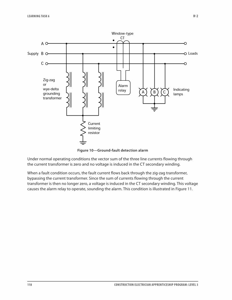
LEARNING TASk 6 H-2
118 CONSTRUCTION ELECTRICIAN APPRENTICESHIP PROGRAM: LEVEL 3
-
Figure 10—Ground-fault detection alarm
Under normal operating conditions the vector sum of the three line currents flowing through the current transformer is zero and no voltage is induced in the CT secondary winding.
When a fault condition occurs, the fault current flows back through the zig-zag transformer, bypassing the current transformer. Since the sum of currents flowing through the current transformer is then no longer zero, a voltage is induced in the CT secondary winding. This voltage causes the alarm relay to operate, sounding the alarm. This condition is illustrated in Figure 11.
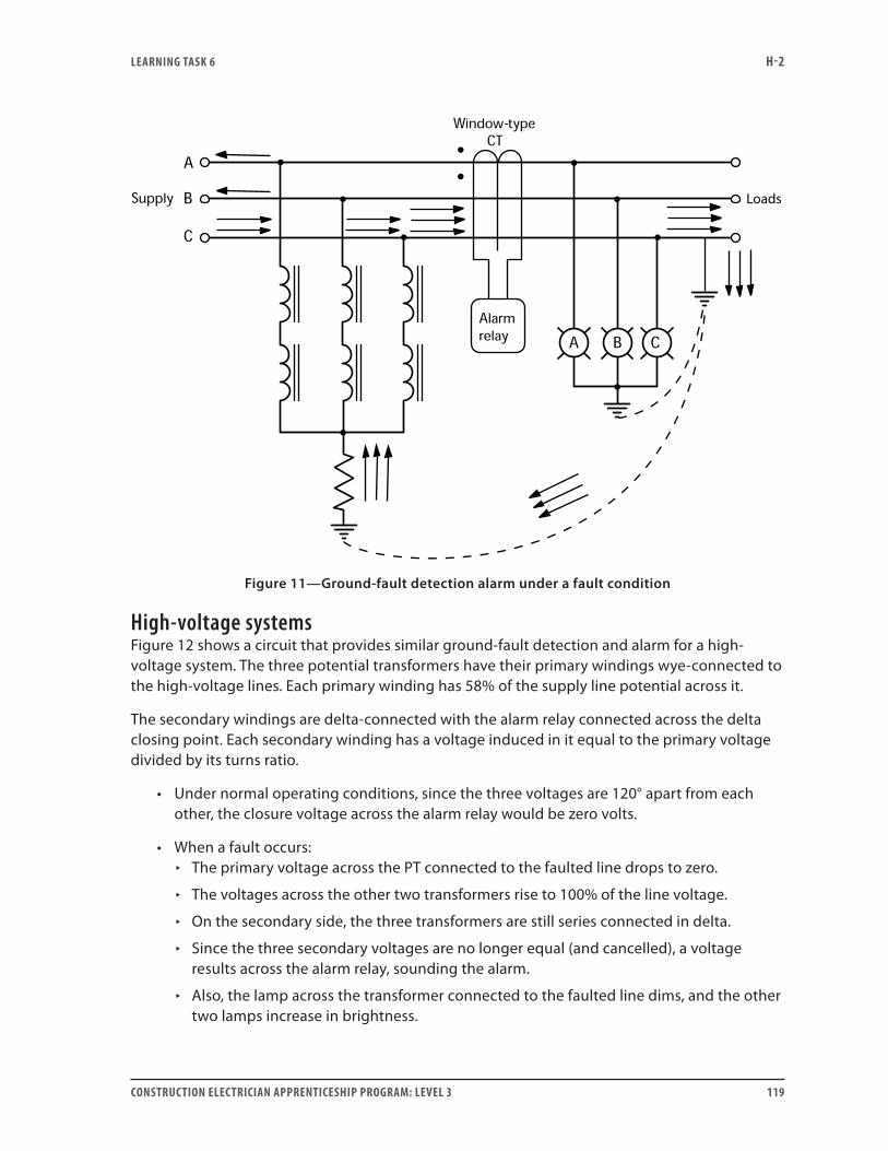
LEARNING TASk 6 H-2
CONSTRUCTION ELECTRICIAN APPRENTICESHIP PROGRAM: LEVEL 3 119
-
Figure 11—Ground-fault detection alarm under a fault condition
High-voltage systemsFigure 12 shows a circuit that provides similar ground-fault detection and alarm for a high-voltage system. The three potential transformers have their primary windings wye-connected to the high-voltage lines. Each primary winding has 58% of the supply line potential across it.
The secondary windings are delta-connected with the alarm relay connected across the delta closing point. Each secondary winding has a voltage induced in it equal to the primary voltage divided by its turns ratio.
• Under normal operating conditions, since the three voltages are 120° apart from each other, the closure voltage across the alarm relay would be zero volts.
• When a fault occurs: ▸ The primary voltage across the PT connected to the faulted line drops to zero.
▸ The voltages across the other two transformers rise to 100% of the line voltage.
▸ On the secondary side, the three transformers are still series connected in delta.
▸ Since the three secondary voltages are no longer equal (and cancelled), a voltage results across the alarm relay, sounding the alarm.
▸ Also, the lamp across the transformer connected to the faulted line dims, and the other two lamps increase in brightness.
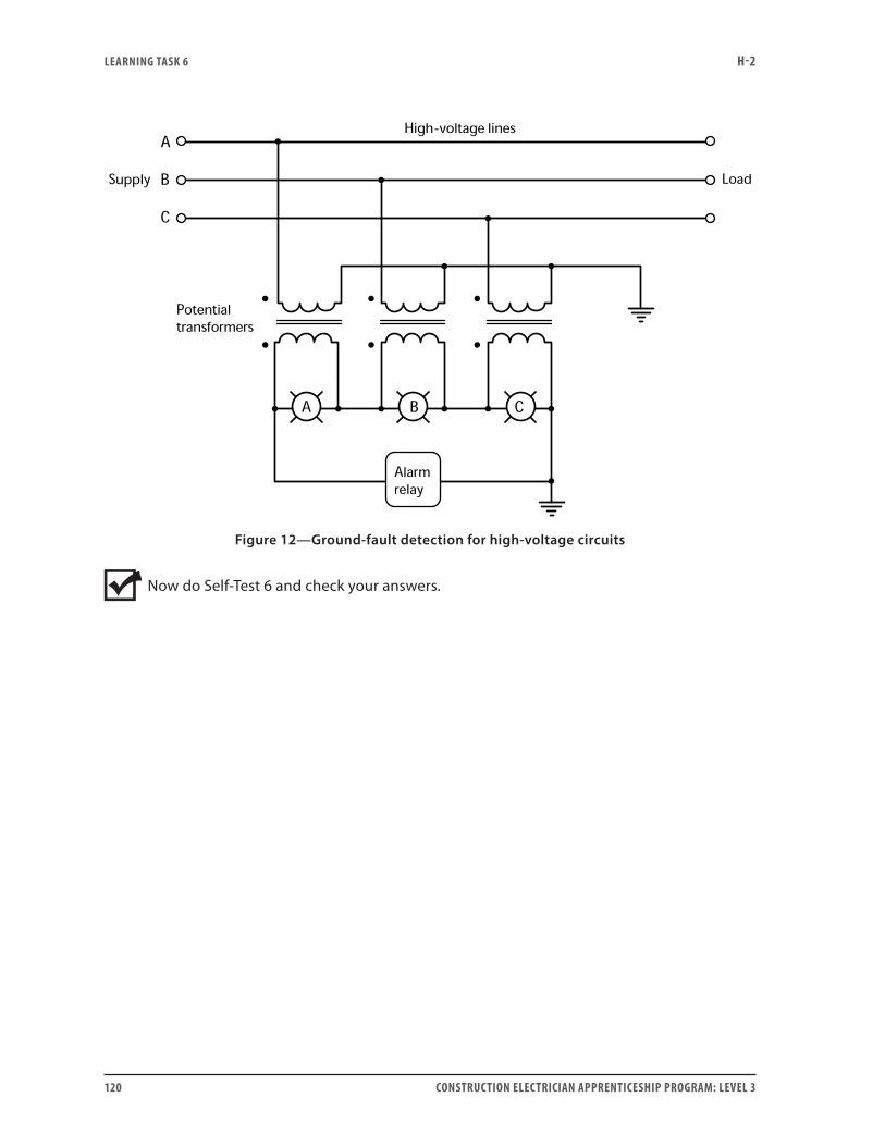
LEARNING TASk 6 H-2
120 CONSTRUCTION ELECTRICIAN APPRENTICESHIP PROGRAM: LEVEL 3
-
Figure 12—Ground-fault detection for high-voltage circuits
Now do Self-Test 6 and check your answers.

LEARNING TASk 6 H-2
CONSTRUCTION ELECTRICIAN APPRENTICESHIP PROGRAM: LEVEL 3 121
Self-Test 6
1. An ammeter connected to the secondary circuit of a current transformer is damaged and needs replacing. What must be done to the secondary terminals of the transformer before the ammeter is removed from the circuit?
2. How do you determine the wattmeter multiplier when fed from a PT and a CT?
3. In an instrument transformer circuit using the two-wattmeter method for power measurement, what should you do if one of the wattmeters reads down-scale?
4. Why are CTs sometimes used in the line conductors to large three-phase motors?
5. What special type of CT is sometimes used for ground-fault detection?
6. When using three PTs for ground-fault detection on high-voltage systems:
a. How are the primary windings connected?
b. How are the secondary windings and alarm relay connected?
Go to the Answer Key at the end of the Learning Guide to check your answers.

122 CONSTRUCTION ELECTRICIAN APPRENTICESHIP PROGRAM: LEVEL 3
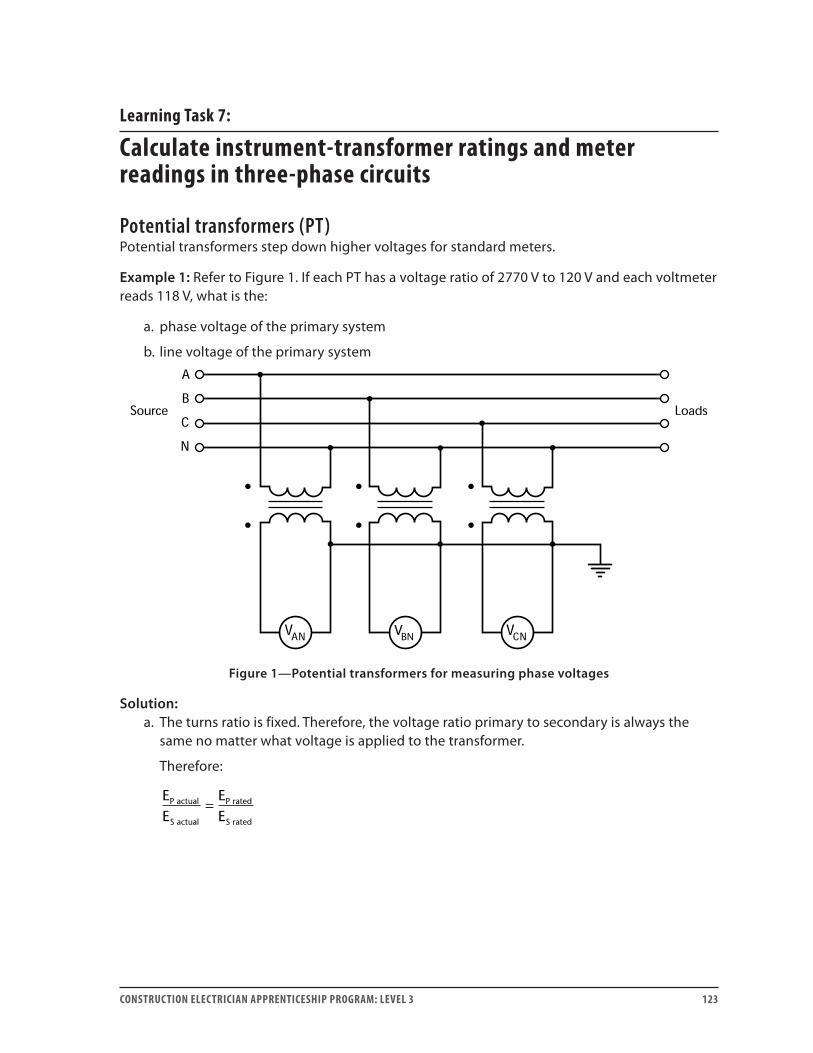
CONSTRUCTION ELECTRICIAN APPRENTICESHIP PROGRAM: LEVEL 3 123
Learning Task 7:
Calculate instrument-transformer ratings and meter readings in three-phase circuits
Potential transformers (PT)Potential transformers step down higher voltages for standard meters.
Example 1: Refer to Figure 1. If each PT has a voltage ratio of 2770 V to 120 V and each voltmeter reads 118 V, what is the:
a. phase voltage of the primary system
b. line voltage of the primary system
Figure 1—Potential transformers for measuring phase voltages
Solution:a. The turns ratio is fixed. Therefore, the voltage ratio primary to secondary is always the
same no matter what voltage is applied to the transformer.
Therefore:
EE
EE
P actual
S actual
P rated
S rated
=
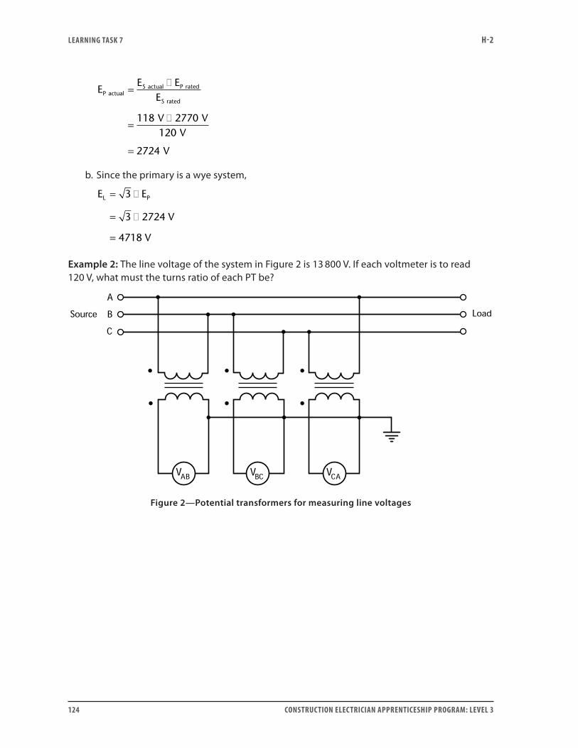
LEARNING TASk 7 H-2
124 CONSTRUCTION ELECTRICIAN APPRENTICESHIP PROGRAM: LEVEL 3
EE E
E
V
P actualS actual P rated
S rated
=�
=�118 2770 V
V
V
120
2724=
b. Since the primary is a wye system,
E E
V
V
L P= �
= �
=
3
3 2724
4718
Example 2: The line voltage of the system in Figure 2 is 13 800 V. If each voltmeter is to read 120 V, what must the turns ratio of each PT be?
Figure 2—Potential transformers for measuring line voltages
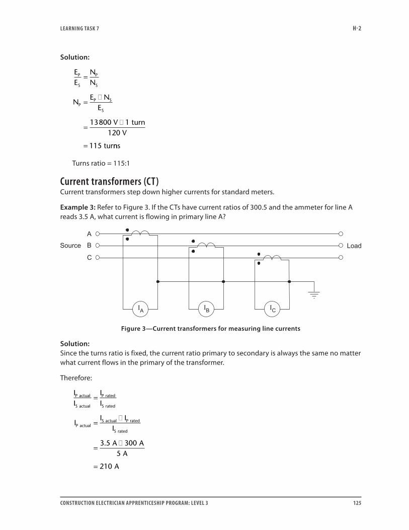
LEARNING TASk 7 H-2
CONSTRUCTION ELECTRICIAN APPRENTICESHIP PROGRAM: LEVEL 3 125
Solution:
EE
NN
NE N
E
P
S
P
S
PP S
S
=
=�
=�
=
13800 V 1 turn120 V
115 turnns
Turns ratio = 115:1
Current transformers (CT)Current transformers step down higher currents for standard meters.
Example 3: Refer to Figure 3. If the CTs have current ratios of 300.5 and the ammeter for line A reads 3.5 A, what current is flowing in primary line A?
Figure 3—Current transformers for measuring line currents
Solution:Since the turns ratio is fixed, the current ratio primary to secondary is always the same no matter what current flows in the primary of the transformer.
Therefore:
II
II
II
P actual
S actual
P rated
S rated
P actualS
=
= actual P rated
S rated
II
A AA
A
�
=�
=
3 5 3005
210
.
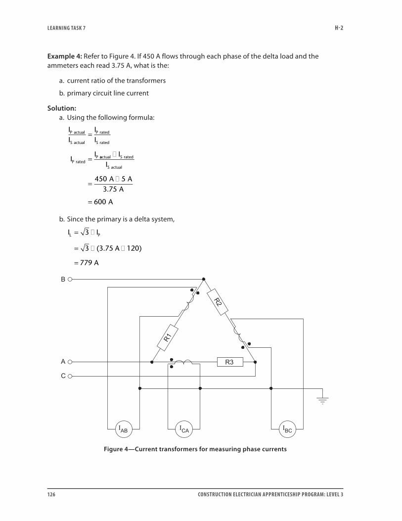
LEARNING TASk 7 H-2
126 CONSTRUCTION ELECTRICIAN APPRENTICESHIP PROGRAM: LEVEL 3
Example 4: Refer to Figure 4. If 450 A flows through each phase of the delta load and the ammeters each read 3.75 A, what is the:
a. current ratio of the transformers
b. primary circuit line current
Solution:a. Using the following formula:
II
II
II
P actual
S actual
P rated
S rated
P ratedP
=
= aactual S rated
S actual
II
A AA
A
�
=�
=
450 53 75
600
.
b. Since the primary is a delta system,
I I
A
A
L P= �
= � �
=
3
3 3 75 120
779
( . )
Figure 4—Current transformers for measuring phase currents
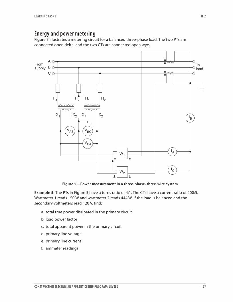
LEARNING TASk 7 H-2
CONSTRUCTION ELECTRICIAN APPRENTICESHIP PROGRAM: LEVEL 3 127
Energy and power meteringFigure 5 illustrates a metering circuit for a balanced three-phase load. The two PTs are connected open delta, and the two CTs are connected open wye.
Figure 5—Power measurement in a three-phase, three-wire system
Example 5: The PTs in Figure 5 have a turns ratio of 4:1. The CTs have a current ratio of 200:5. Wattmeter 1 reads 150 W and wattmeter 2 reads 444 W. If the load is balanced and the secondary voltmeters read 120 V, find:
a. total true power dissipated in the primary circuit
b. load power factor
c. total apparent power in the primary circuit
d. primary line voltage
e. primary line current
f. ammeter readings
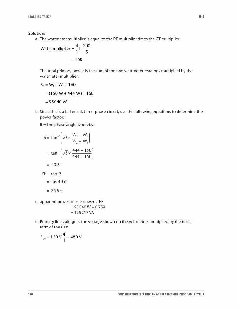
LEARNING TASk 7 H-2
128 CONSTRUCTION ELECTRICIAN APPRENTICESHIP PROGRAM: LEVEL 3
Solution:a. The wattmeter multiplier is equal to the PT multiplier times the CT multiplier:
Watts multiplier = �
=
41
2005
160
The total primary power is the sum of the two wattmeter readings multiplied by the wattmeter multiplier:
P W W
W W
W
T = + �
= + �
=
1 2 160
150 444 160
95040
( )
b. Since this is a balanced, three-phase circuit, use the following equations to determine the power factor:
θ = The phase angle whereby:
θ = ×−+
= ×−
−
−
tan
tan
1 2 1
2 1
1
3
3444 1504
W WW W
444 150
40 6
75 9
+
= °
=
=
.
cos
= cos 40.6º
. %
PF θ
c. apparent power = true power ÷ PF = 95 040 W ÷ 0.759 = 125 217 VA
d. Primary line voltage is the voltage shown on the voltmeters multiplied by the turns ratio of the PTs:
E V Vpri = =120
41
480
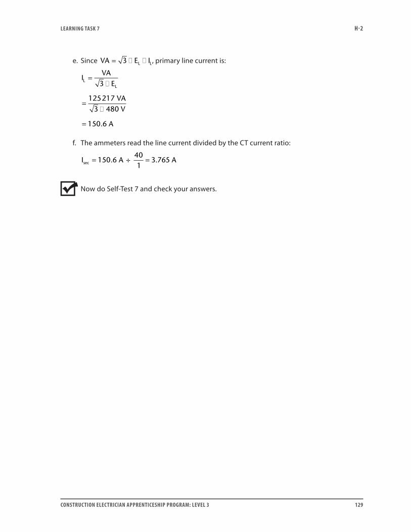
LEARNING TASk 7 H-2
CONSTRUCTION ELECTRICIAN APPRENTICESHIP PROGRAM: LEVEL 3 129
e. Since VA E IL L= � �3 , primary line current is:
IVA
E
VAV
A
LL
=�
=�
=
3
1252173 480
150 6.
f. The ammeters read the line current divided by the CT current ratio:
I A Asec . .= =150 6
401
3 765÷
Now do Self-Test 7 and check your answers.
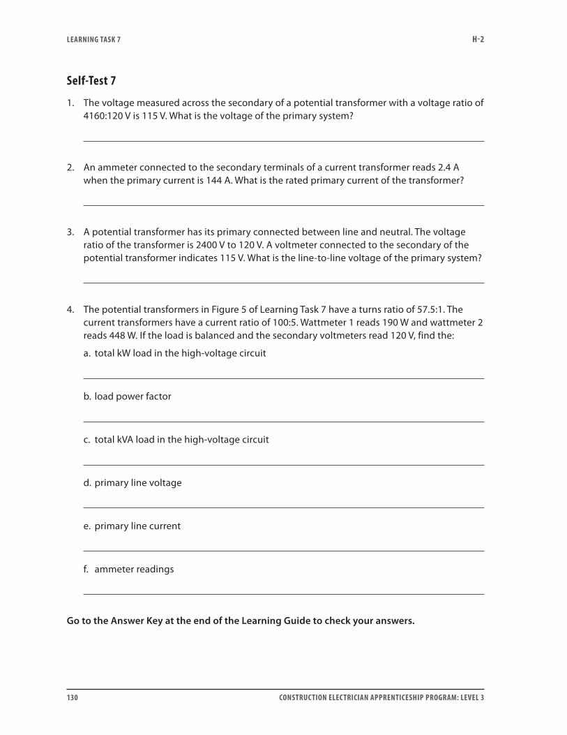
LEARNING TASk 7 H-2
130 CONSTRUCTION ELECTRICIAN APPRENTICESHIP PROGRAM: LEVEL 3
Self-Test 7
1. The voltage measured across the secondary of a potential transformer with a voltage ratio of 4160:120 V is 115 V. What is the voltage of the primary system?
2. An ammeter connected to the secondary terminals of a current transformer reads 2.4 A when the primary current is 144 A. What is the rated primary current of the transformer?
3. A potential transformer has its primary connected between line and neutral. The voltage ratio of the transformer is 2400 V to 120 V. A voltmeter connected to the secondary of the potential transformer indicates 115 V. What is the line-to-line voltage of the primary system?
4. The potential transformers in Figure 5 of Learning Task 7 have a turns ratio of 57.5:1. The current transformers have a current ratio of 100:5. Wattmeter 1 reads 190 W and wattmeter 2 reads 448 W. If the load is balanced and the secondary voltmeters read 120 V, find the:
a. total kW load in the high-voltage circuit
b. load power factor
c. total kVA load in the high-voltage circuit
d. primary line voltage
e. primary line current
f. ammeter readings
Go to the Answer Key at the end of the Learning Guide to check your answers.
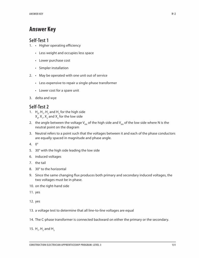
ANSwER kEY H-2
CONSTRUCTION ELECTRICIAN APPRENTICESHIP PROGRAM: LEVEL 3 131
Answer key
Self-Test 11. • Higher operating efficiency
• Less weight and occupies less space
• Lower purchase cost
• Simpler installation
2. • May be operated with one unit out of service
• Less expensive to repair a single-phase transformer
• Lower cost for a spare unit
3. delta and wye
Self-Test 21. H0, H1, H2 and H3 for the high side
X0, X1, X2 and X3 for the low side
2. the angle between the voltage VAN of the high side and VAN of the low side where N is the neutral point on the diagram
3. Neutral refers to a point such that the voltages between it and each of the phase conductors are equally spaced in magnitude and phase angle.
4. 0°
5. 30° with the high side leading the low side
6. induced voltages
7. the tail
8. 30° to the horizontal
9. Since the same changing flux produces both primary and secondary induced voltages, the two voltages must be in phase.
10. on the right-hand side
11. yes
12. yes
13. a voltage test to determine that all line-to-line voltages are equal
14. The C-phase transformer is connected backward on either the primary or the secondary.
15. H1, H2 and H3
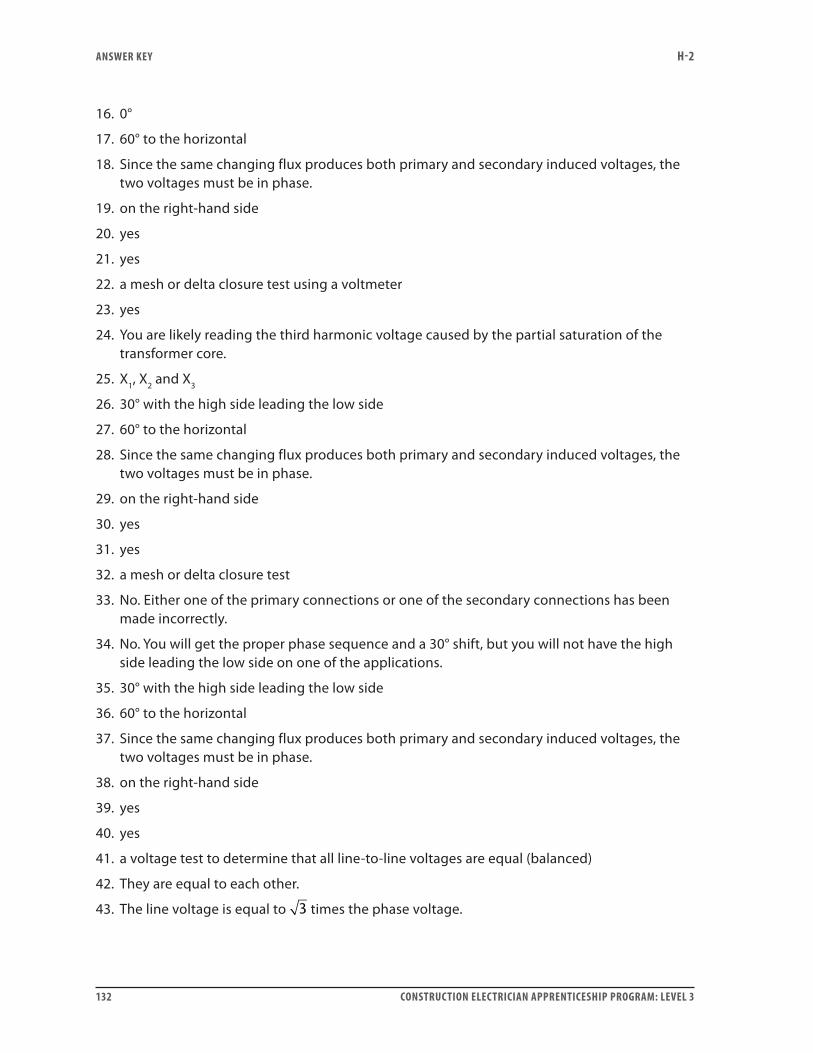
ANSwER kEY H-2
132 CONSTRUCTION ELECTRICIAN APPRENTICESHIP PROGRAM: LEVEL 3
16. 0°
17. 60° to the horizontal
18. Since the same changing flux produces both primary and secondary induced voltages, the two voltages must be in phase.
19. on the right-hand side
20. yes
21. yes
22. a mesh or delta closure test using a voltmeter
23. yes
24. You are likely reading the third harmonic voltage caused by the partial saturation of the transformer core.
25. X1, X2 and X3
26. 30° with the high side leading the low side
27. 60° to the horizontal
28. Since the same changing flux produces both primary and secondary induced voltages, the two voltages must be in phase.
29. on the right-hand side
30. yes
31. yes
32. a mesh or delta closure test
33. No. Either one of the primary connections or one of the secondary connections has been made incorrectly.
34. No. You will get the proper phase sequence and a 30° shift, but you will not have the high side leading the low side on one of the applications.
35. 30° with the high side leading the low side
36. 60° to the horizontal
37. Since the same changing flux produces both primary and secondary induced voltages, the two voltages must be in phase.
38. on the right-hand side
39. yes
40. yes
41. a voltage test to determine that all line-to-line voltages are equal (balanced)
42. They are equal to each other.
43. The line voltage is equal to 3 times the phase voltage.
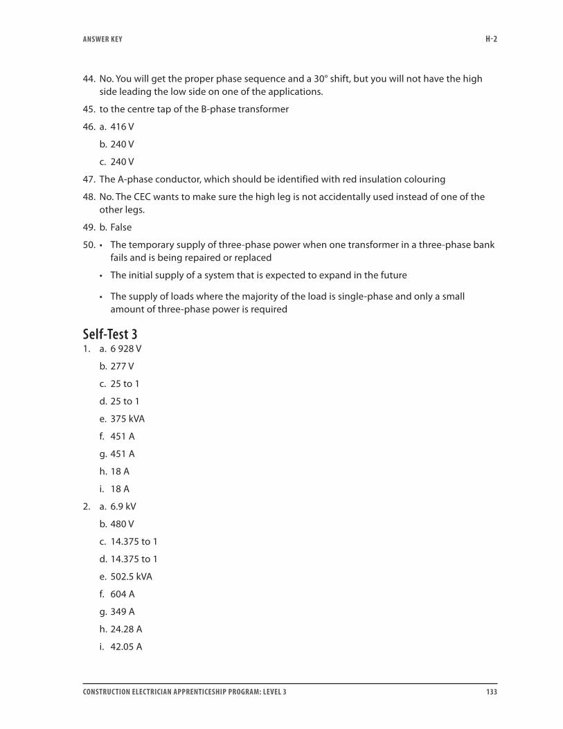
ANSwER kEY H-2
CONSTRUCTION ELECTRICIAN APPRENTICESHIP PROGRAM: LEVEL 3 133
44. No. You will get the proper phase sequence and a 30° shift, but you will not have the high side leading the low side on one of the applications.
45. to the centre tap of the B-phase transformer
46. a. 416 V
b. 240 V
c. 240 V
47. The A-phase conductor, which should be identified with red insulation colouring
48. No. The CEC wants to make sure the high leg is not accidentally used instead of one of the other legs.
49. b. False
50. • The temporary supply of three-phase power when one transformer in a three-phase bank fails and is being repaired or replaced
• The initial supply of a system that is expected to expand in the future
• The supply of loads where the majority of the load is single-phase and only a small amount of three-phase power is required
Self-Test 31. a. 6 928 V
b. 277 V
c. 25 to 1
d. 25 to 1
e. 375 kVA
f. 451 A
g. 451 A
h. 18 A
i. 18 A
2. a. 6.9 kV
b. 480 V
c. 14.375 to 1
d. 14.375 to 1
e. 502.5 kVA
f. 604 A
g. 349 A
h. 24.28 A
i. 42.05 A
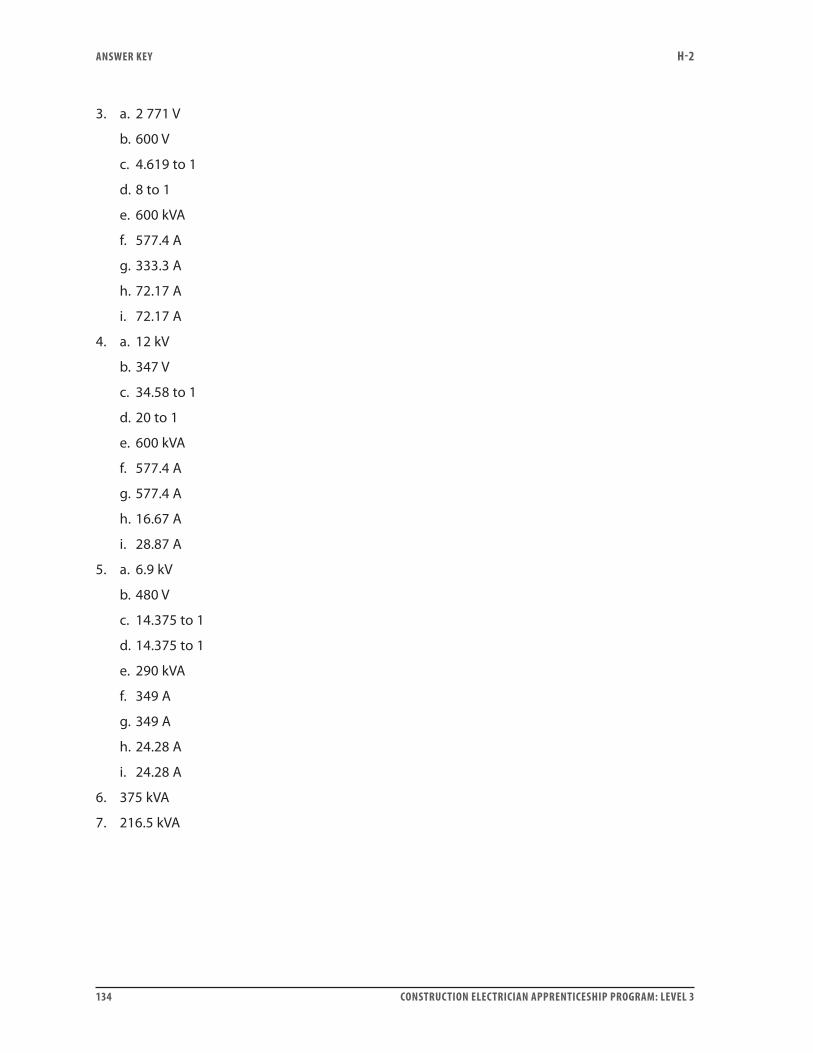
ANSwER kEY H-2
134 CONSTRUCTION ELECTRICIAN APPRENTICESHIP PROGRAM: LEVEL 3
3. a. 2 771 V
b. 600 V
c. 4.619 to 1
d. 8 to 1
e. 600 kVA
f. 577.4 A
g. 333.3 A
h. 72.17 A
i. 72.17 A
4. a. 12 kV
b. 347 V
c. 34.58 to 1
d. 20 to 1
e. 600 kVA
f. 577.4 A
g. 577.4 A
h. 16.67 A
i. 28.87 A
5. a. 6.9 kV
b. 480 V
c. 14.375 to 1
d. 14.375 to 1
e. 290 kVA
f. 349 A
g. 349 A
h. 24.28 A
i. 24.28 A
6. 375 kVA
7. 216.5 kVA
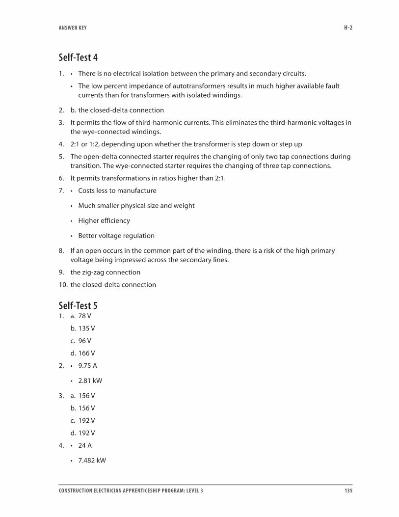
ANSwER kEY H-2
CONSTRUCTION ELECTRICIAN APPRENTICESHIP PROGRAM: LEVEL 3 135
Self-Test 41. • There is no electrical isolation between the primary and secondary circuits.
• The low percent impedance of autotransformers results in much higher available fault currents than for transformers with isolated windings.
2. b. the closed-delta connection
3. It permits the flow of third-harmonic currents. This eliminates the third-harmonic voltages in the wye-connected windings.
4. 2:1 or 1:2, depending upon whether the transformer is step down or step up
5. The open-delta connected starter requires the changing of only two tap connections during transition. The wye-connected starter requires the changing of three tap connections.
6. It permits transformations in ratios higher than 2:1.
7. • Costs less to manufacture
• Much smaller physical size and weight
• Higher efficiency
• Better voltage regulation
8. If an open occurs in the common part of the winding, there is a risk of the high primary voltage being impressed across the secondary lines.
9. the zig-zag connection
10. the closed-delta connection
Self-Test 51. a. 78 V
b. 135 V
c. 96 V
d. 166 V
2. • 9.75 A
• 2.81 kW
3. a. 156 V
b. 156 V
c. 192 V
d. 192 V
4. • 24 A
• 7.482 kW
ANSwER kEY H-2
136 CONSTRUCTION ELECTRICIAN APPRENTICESHIP PROGRAM: LEVEL 3
5. 130 kVA
6. 5 kVA
Self-Test 61. The secondary winding must be short-circuited to prevent dangerously high voltages from
being induced in the secondary circuit due to the open.
2. wattmeter multiplier = CT ratio × PT ratio
3. Reverse the potential transformer leads only to the wattmeter so that it will read up-scale.
4. To supply the overload relay (heaters) protection so that smaller size O/L relays can be used.
5. window or donut-type CTs
6. a. wye-connected with the neutral point grounded
b. delta-connected with the alarm relay across the delta-closure point
Self-Test 71. 3987 V
2. 300 A
3. 3984 V
4. a. 733.7 kW
b. 81.9%
c. 895.8 kVA
d. 6900 V
e. 74.96 A
f. 3.75 A


ISBN 978-0-7726-6813-4
9 780772 6681347960003596