contract for the centralized procurement and preassembly
TRANSCRIPT
ITER RESTRICTED 1
Contract for the Centralized Procurement and Preassembly of Piping Systems for ITER
ADDENDUM 1
Summary for the Cooling Water System (CWS)
Purpose The purpose of this Contract is the Centralized Procurement and Preassembly of Piping Systems for ITER. The major ITER piping system is the Cooling Water System (CWS). Addendum 1 gives details of the requirements for the CWS for this contract.
Background The ITER Cooling Water System (CWS) consists of the Tokamak Cooling Water System (TCWS), the Component Cooling Water System (CCWS), the Chilled Water System (CHWS), and the Heat Rejection System (HRS)
The TCWS is designed to reject all the heat generated in the plasma and transmitted to the in-vessel components to the intermediate closed loop Component Cooling Water System (CCWS-1) and then to the environment via the open Heat Rejection System (HRS). In particular, during the D-T Plasma phase, the heat transmitted and generated in the in-vessel component (IVCs) will be transferred, through the Primary Heat Transfer Systems (PHTSs) to the intermediated closed Component Cooling Water System (CCWS-1) and then, via the open loop Heat Rejection System (HRS), to the environment.
The HRS also absorbs heats through the CCWS-2 from other non-nuclear systems like the Chilled Water System (CHWS), the Cryogenic System, the Steady State Electrical Power Network (SSEPN) and other auxiliary systems. The CCWS-2 is further divided in CCWS-2A, 2B, 2C, and 2D to provide separated chemical control and prevent galvanic corrosion among the different material (SS, Cu, Al) of the clients’ components.
CHWS is divided in CHWS-H1 for SIC systems and CHWS-H2 for non-sic components. The HRS rejects all the heat from ITER components (nuclear and non-nuclear) to the environment.
The total heat load to be removed at reference plasma operation by the CWS is about 1200 MW with the following single design requirements (excluding contemporary operations but including margin):
• TCWS is designed for about 1100 MW – 6100 kg/s; • CCWS-1 is designed for about 982 MW – 5800 kg/s; • CCWS-2 is designed for about 164 MW – 4300 kg/s with the:
o CCWS-2A is designed for about 40 MW – 900 kg/s; o CCWS-2B is designed for about 28 MW – 1100 kg/s; o CCWS-2C is designed for about 6 MW – 160 kg/s;
ITER RESTRICTED 2
o CCWS-2D is designed for about 90 MW – 2150 kg/s;
• CHWS-H1 is designed for about 2.2 MW – 90 kg/s; • CHWS-H2 is designed for about 27.5 MW – 1100 kg/s; • HRS is designed for about 500 MW – 10500 kg/s.
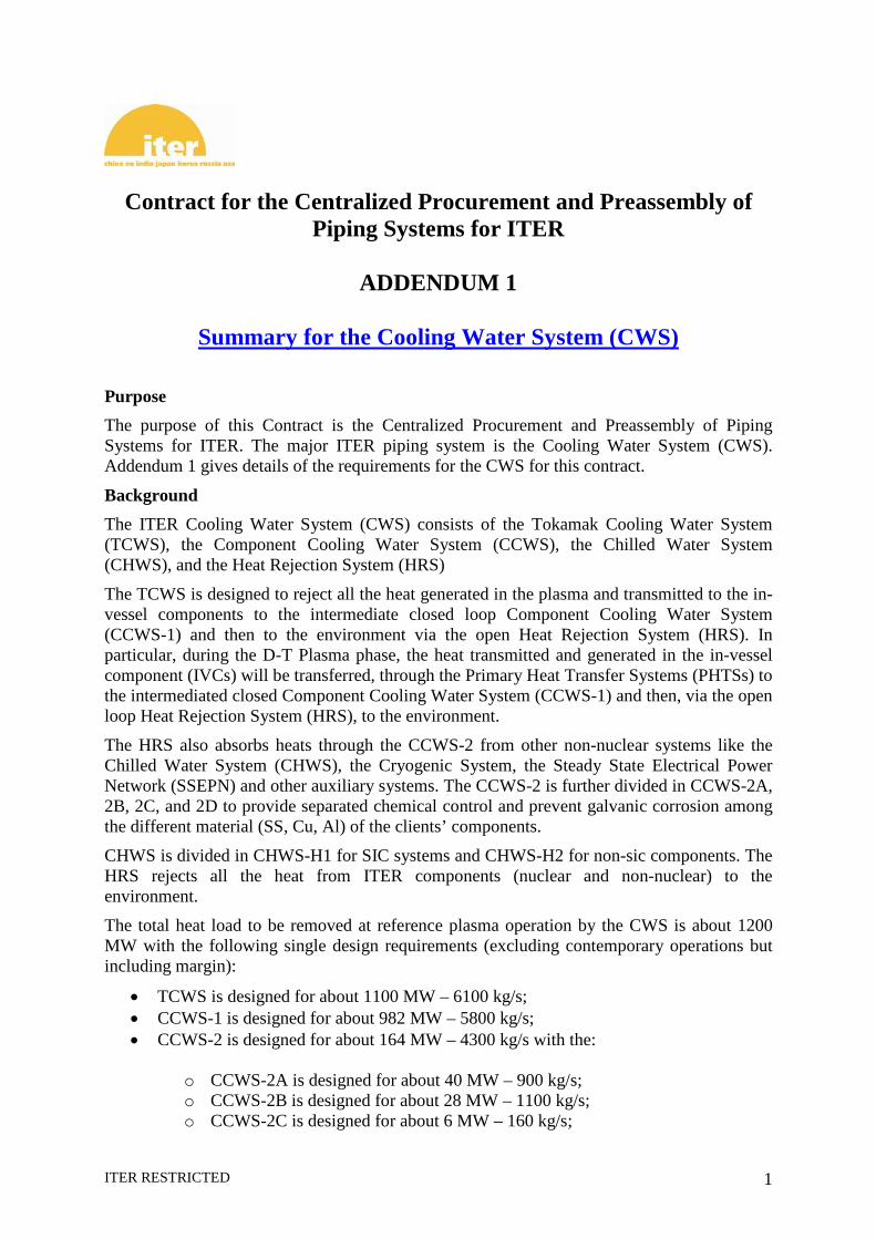
The CCWS, CHWS and HRS systems are arranged as reported in the Fig. 1. The piping distribution is divided in two groups:
1. the piping distributed mainly in trenches or buried outside the buildings; 2. the piping distributed inside the buildings with the final connection to the clients’
stubs.
The overall piping length and weight is reported in the table in the Fig. 1 for each group.
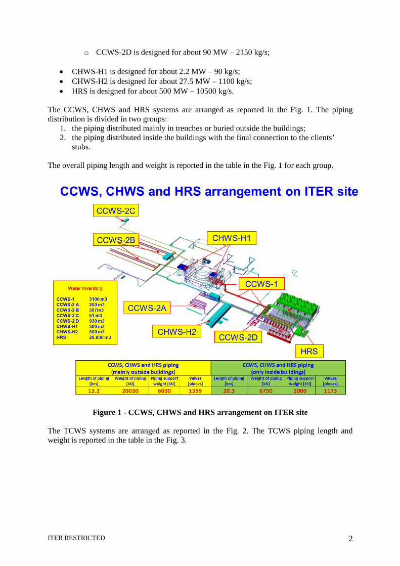
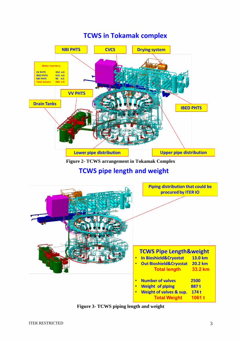
Figure 1 - CCWS, CHWS and HRS arrangement on ITER site The TCWS systems are arranged as reported in the Fig. 2. The TCWS piping length and weight is reported in the table in the Fig. 3.
ITER RESTRICTED 3
Figure 2- TCWS arrangement in Tokamak Complex
Figure 3- TCWS piping length and weight
ITER RESTRICTED 4
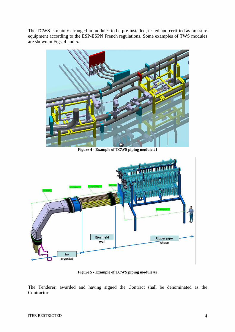
The TCWS is mainly arranged in modules to be pre-installed, tested and certified as pressure equipment according to the ESP-ESPN French regulations. Some examples of TWS modules are shown in Figs. 4 and 5.
Figure 4 - Example of TCWS piping module #1
Figure 5 - Example of TCWS piping module #2
The Tenderer, awarded and having signed the Contract shall be denominated as the Contractor.
ITER RESTRICTED 5
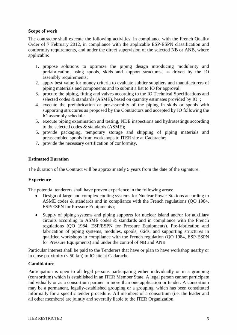
Scope of work The contractor shall execute the following activities, in compliance with the French Quality Order of 7 February 2012, in compliance with the applicable ESP-ESPN classification and conformity requirements, and under the direct supervision of the selected NB or ANB, where applicable:
1. propose solutions to optimize the piping design introducing modularity and prefabrication, using spools, skids and support structures, as driven by the IO assembly requirements;
2. apply best value for money criteria to evaluate subtier suppliers and manufacturers of piping materials and components and to submit a list to IO for approval;
3. procure the piping, fitting and valves according to the IO Technical Specifications and selected codes & standards (ASME), based on quantity estimates provided by IO. ;
4. execute the prefabrication or pre-assembly of the piping in skids or spools with supporting structures as proposed by the Contractors and accepted by IO following the IO assembly schedule
5. execute piping examination and testing, NDE inspections and hydrotestings according to the selected codes & standards (ASME);
6. provide packaging, temporary storage and shipping of piping materials and preassembled spools from workshops to ITER site at Cadarache;
7. provide the necessary certification of conformity.
Estimated Duration
The duration of the Contract will be approximately 5 years from the date of the signature.
Experience
The potential tenderers shall have proven experience in the following areas: • Design of large and complex cooling systems for Nuclear Power Stations according to
ASME codes & standards and in compliance with the French regulations (QO 1984, ESP/ESPN for Pressure Equipments);
• Supply of piping systems and piping supports for nuclear island and/or for auxiliary circuits according to ASME codes & standards and in compliance with the French regulations (QO 1984, ESP/ESPN for Pressure Equipments). Pre-fabrication and fabrication of piping systems, modules, spools, skids, and supporting structures in qualified workshops in compliance with the French regulation (QO 1984, ESP-ESPN for Pressure Equipments) and under the control of NB and ANB
Particular interest shall be paid to the Tenderers that have or plan to have workshop nearby or in close proximity (< 50 km) to IO site at Cadarache.
Candidature Participation is open to all legal persons participating either individually or in a grouping (consortium) which is established in an ITER Member State. A legal person cannot participate individually or as a consortium partner in more than one application or tender. A consortium may be a permanent, legally-established grouping or a grouping, which has been constituted informally for a specific tender procedure. All members of a consortium (i.e. the leader and all other members) are jointly and severally liable to the ITER Organization.

ITER RESTRICTED 6
The consortium groupings shall be presented at the pre-qualification stage. The tenderer’s composition cannot be modified without the approval of the ITER Organization after the pre-qualification.
Legal entities belonging to the same legal grouping are allowed to participate separately if they are able to demonstrate independent technical and financial capacities. Candidates (individual or consortium) must comply with the selection criteria. The IO reserves the right to disregard duplicated reference projects and may exclude such legal entities from the pre-qualification procedure.

ITER RESTRICTED 7
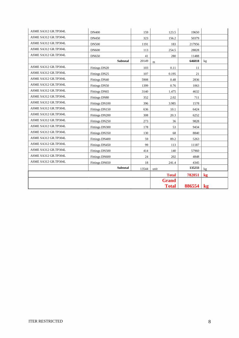
Annex -1 Tab I - Draft estimation of TCWS piping
Steel- Grade SIZE Quantity Weight Total Weight Remarks
mm. Unit kg/unit kg
Piping inside Bioshield &Cryostat ASME SA312 GR.TP304L Cobalt controlled DN25 142.3 2.52 359 Cobalt < 0.05%
ASME SA312 GR.TP304L Cobalt controlled DN40 6843.5 4.08 27921 Cobalt < 0.05%
ASME SA312 GR.TP304L Cobalt controlled DN50 1639.7 5.47 8969 Cobalt < 0.05%
ASME SA312 GR.TP304L Cobalt controlled DN65 1930.5 8.69 16776 Cobalt < 0.05%
ASME SA312 GR.TP304L Cobalt controlled DN90 (guard) 1450 13.57 19677 Cobalt < 0.05%
ASME SA312 GR.TP304L Cobalt controlled DN100 276.5 16.18 4473 Cobalt < 0.05%
ASME SA312 GR.TP304L Cobalt controlled DN150 (guard) 504 28.44 14335 Cobalt < 0.05%
ASME SA312 GR.TP304L Cobalt controlled DN200 (guard) 227.6 42.82 9744 Cobalt < 0.05%
Subtotal 13014.1 m 102254 kg ASME SA312 GR.TP304L Cobalt controlled TEE DN40 26 0.48 12 Cobalt < 0.05%
ASME SA312 GR.TP304L Cobalt controlled TEE DN100 (pipe) 28 3.985 112 Cobalt < 0.05%
ASME SA312 GR.TP304L Cobalt controlled TEE DN150 (guard) 28 10.1 283 Cobalt < 0.05%
ASME SA312 GR.TP304L Cobalt controlled REDUCER DN40-DN25 62 0.48 30 Cobalt < 0.05%
ASME SA312 GR.TP304L Cobalt controlled REDUCER DN100-DN65 56 3.985 223 Cobalt < 0.05%
ASME SA312 GR.TP304L Cobalt controlled REDUCER DN150-DN90 56 10.1 566 Cobalt < 0.05%
ASME SA312 GR.TP304L Cobalt controlled ELBOW DN25 59 0.195 12 Cobalt < 0.05%
ASME SA312 GR.TP304L Cobalt controlled ELBOW DN40 13 0.48 6 Cobalt < 0.05%
ASME SA312 GR.TP304L Cobalt controlled ELBOW DN65 270 1.475 398 Cobalt < 0.05%
ASME SA312 GR.TP304L Cobalt controlled ELBOW DN150 (pipe) 20 10.1 202 Cobalt < 0.05%
ASME SA312 GR.TP304L Cobalt controlled ELBOW DN200 (guard) 20 20.3 406 Cobalt < 0.05%
Subtotal 638 unit 2249 kg
Total 104503 kg Piping outside Bioshield &Cryostat
ASME SA312 GR.TP304L DN20 106 1.7 180
ASME SA312 GR.TP304L DN25 279 2.52 704
ASME SA312 GR.TP304L DN40 4878 4.08 19904
ASME SA312 GR.TP304L DN50 1578 5.47 8632
ASME SA312 GR.TP304L DN65 5508 8.69 47864
ASME SA312 GR.TP304L DN80 964 11.36 10952
ASME SA312 GR.TP304L DN100 1015 16.18 16415
ASME SA312 GR.TP304L DN150 984 28.44 27991
ASME SA312 GR.TP304L DN200 1136 42.82 48644
ASME SA312 GR.TP304L DN250 763 60.7 46313
ASME SA312 GR.TP304L DN300 735 75.9 55768
ASME SA312 GR.TP304L DN350 375 93.7 35150
ITER RESTRICTED 8
ASME SA312 GR.TP304L DN400 159 123.5 19650
ASME SA312 GR.TP304L DN450 323 156.2 50379
ASME SA312 GR.TP304L DN500 1191 183 217956
ASME SA312 GR.TP304L DN600 113 254.5 28828
ASME SA312 GR.TP304L DN650 41 280 11488
Subtotal 20149 m 646818 kg
ASME SA312 GR.TP304L Fittings DN20 103 0.11 11
ASME SA312 GR.TP304L Fittings DN25 107 0.195 21
ASME SA312 GR.TP304L Fittings DN40 5908 0.48 2836 ASME SA312 GR.TP304L Fittings DN50 1399 0.76 1063 ASME SA312 GR.TP304L Fittings DN65 3140 1.475 4632 ASME SA312 GR.TP304L Fittings DN80 352 2.02 711 ASME SA312 GR.TP304L Fittings DN100 396 3.985 1578 ASME SA312 GR.TP304L Fittings DN150 636 10.1 6424 ASME SA312 GR.TP304L Fittings DN200 308 20.3 6252 ASME SA312 GR.TP304L Fittings DN250 273 36 9828 ASME SA312 GR.TP304L Fittings DN300 178 53 9434 ASME SA312 GR.TP304L Fittings DN350 130 68 8840 ASME SA312 GR.TP304L Fittings DN400 59 89.2 5263 ASME SA312 GR.TP304L Fittings DN450 99 113 11187 ASME SA312 GR.TP304L Fittings DN500 414 140 57960 ASME SA312 GR.TP304L Fittings DN600 24 202 4848 ASME SA312 GR.TP304L Fittings DN650 18 241.4 4345
Subtotal 13544 unit 135233 kg
Total 782051 kg
Grand
Total 886554 kg
ITER RESTRICTED 9
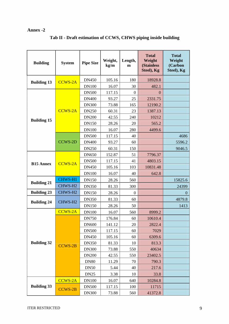
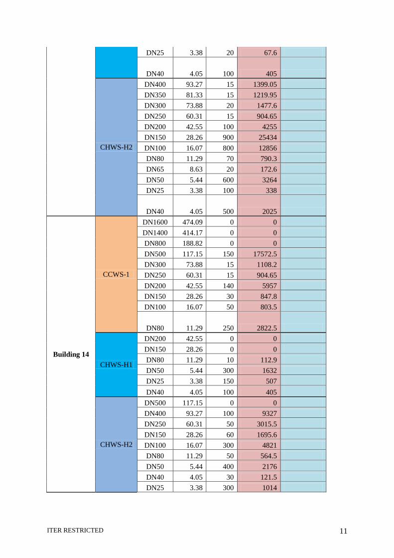
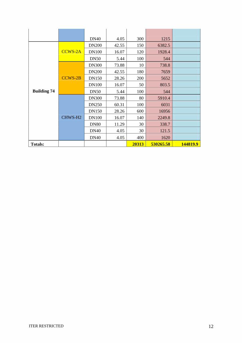
Annex -2 Tab II - Draft estimation of CCWS, CHWS piping inside building
Building System Pipe Size Weight, kg/m
Length, m
Total Weight
(Stainless Steel), Kg
Total Weight (Carbon
Steel), Kg
Building 13 CCWS-2A DN450 105.16 180 18928.8 DN100 16.07 30 482.1
Building 15
CCWS-2A
DN500 117.15 0 0 DN400 93.27 25 2331.75 DN300 73.88 165 12190.2 DN250 60.31 23 1387.13 DN200 42.55 240 10212 DN150 28.26 20 565.2 DN100 16.07 280 4499.6
CCWS-2D DN500 117.15 40 4686 DN400 93.27 60 5596.2 DN250 60.31 150 9046.5
B15 Annex CCWS-2A
DN650 152.87 51 7796.37 DN500 117.15 41 4803.15 DN450 105.16 103 10831.48 DN100 16.07 40 642.8
Building 21 CHWS-H1 DN150 28.26 560 15825.6 CHWS-H2 DN350 81.33 300 24399
Building 23 CHWS-H2 DN150 28.26 0 0
Building 24 CHWS-H2 DN350 81.33 60 4879.8 DN150 28.26 50 1413
Building 32
CCWS-2A DN100 16.07 560 8999.2
CCWS-2B
DN750 176.84 60 10610.4 DN600 141.12 20 2822.4 DN500 117.15 60 7029 DN450 105.16 60 6309.6 DN350 81.33 10 813.3 DN300 73.88 550 40634 DN200 42.55 550 23402.5 DN80 11.29 70 790.3 DN50 5.44 40 217.6 DN25 3.38 10 33.8
Building 33 CCWS-2A DN100 16.07 640 10284.8
CCWS-2B DN500 117.15 100 11715 DN300 73.88 560 41372.8
ITER RESTRICTED 10
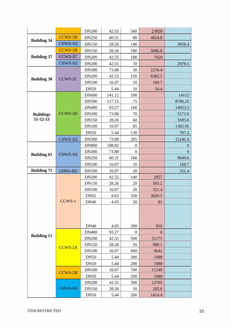
DN200 42.55 560 23828
Building 34 CCWS-2B DN250 60.31 80 4824.8 CHWS-H2 DN150 28.26 140 3956.4
Building 37 CCWS-2B DN150 28.26 180 5086.8 CCWS-2C DN200 42.55 180 7659 CHWS-H2 DN200 42.55 70 2978.5
Building 38 CCWS-2C
DN300 73.88 30 2216.4 DN200 42.55 150 6382.5 DN100 16.07 10 160.7 DN50 5.44 10 54.4
Buildings 51-52-53
CCWS-2D
DN600 141.12 100 14112 DN500 117.15 75 8786.25 DN400 93.27 160 14923.2 DN300 73.88 70 5171.6 DN150 28.26 60 1695.6 DN100 16.07 85 1365.95 DN50 5.44 130 707.2
CHWS-H2 DN300 73.88 205 15145.4
Building 61 CHWS-H2
DN800 188.82 0 0 DN300 73.88 0 0 DN250 60.31 160 9649.6 DN100 16.07 10 160.7
Building 71 CHWs-H2 DN100 16.07 20 321.4
Building 11
CCWS-1
DN200 42.55 140 5957 DN150 28.26 20 565.2 DN100 16.07 20 321.4 DN65 8.63 350 3020.5 DN40 4.05 20 81
DN40 4.05 200 810
CCWS-2A
DN400 93.27 0 0 DN200 42.55 500 21275 DN150 28.26 35 989.1 DN100 16.07 600 9642 DN50 5.44 200 1088 DN50 5.44 200 1088
CCWS-2B DN100 16.07 700 11249 DN50 5.44 200 1088
CHWS-H1 DN200 42.55 300 12765 DN150 28.26 10 282.6 DN50 5.44 260 1414.4
ITER RESTRICTED 11
DN25 3.38 20 67.6
DN40 4.05 100 405
CHWS-H2
DN400 93.27 15 1399.05 DN350 81.33 15 1219.95 DN300 73.88 20 1477.6 DN250 60.31 15 904.65 DN200 42.55 100 4255 DN150 28.26 900 25434 DN100 16.07 800 12856 DN80 11.29 70 790.3 DN65 8.63 20 172.6 DN50 5.44 600 3264 DN25 3.38 100 338
DN40 4.05 500 2025
Building 14
CCWS-1
DN1600 474.09 0 0 DN1400 414.17 0 0 DN800 188.82 0 0 DN500 117.15 150 17572.5 DN300 73.88 15 1108.2 DN250 60.31 15 904.65 DN200 42.55 140 5957 DN150 28.26 30 847.8 DN100 16.07 50 803.5
DN80 11.29 250 2822.5
CHWS-H1
DN200 42.55 0 0 DN150 28.26 0 0 DN80 11.29 10 112.9 DN50 5.44 300 1632 DN25 3.38 150 507 DN40 4.05 100 405
CHWS-H2
DN500 117.15 0 0 DN400 93.27 100 9327 DN250 60.31 50 3015.5 DN150 28.26 60 1695.6 DN100 16.07 300 4821 DN80 11.29 50 564.5 DN50 5.44 400 2176 DN40 4.05 30 121.5 DN25 3.38 300 1014
ITER RESTRICTED 12
DN40 4.05 300 1215
Building 74
CCWS-2A DN200 42.55 150 6382.5 DN100 16.07 120 1928.4 DN50 5.44 100 544
CCWS-2B
DN300 73.88 10 738.8 DN200 42.55 180 7659 DN150 28.26 200 5652 DN100 16.07 50 803.5 DN50 5.44 100 544
CHWS-H2
DN300 73.88 80 5910.4 DN250 60.31 100 6031 DN150 28.26 600 16956 DN100 16.07 140 2249.8 DN80 11.29 30 338.7 DN40 4.05 30 121.5 DN40 4.05 400 1620
Totals: 20313 530265.58 144819.9
ITER RESTRICTED 13
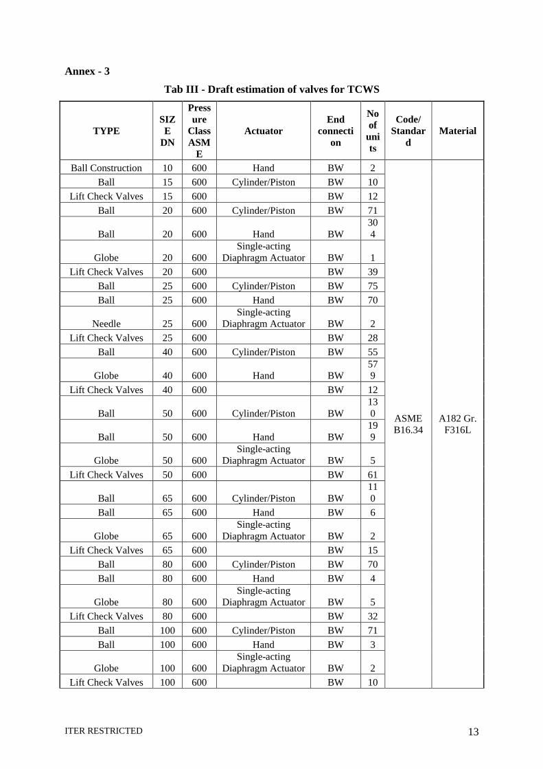
Annex - 3 Tab III - Draft estimation of valves for TCWS
TYPE SIZE
DN
Pressure
Class ASM
E
Actuator End
connection
No of
units
Code/ Standar
d Material
Ball Construction 10 600 Hand BW 2
ASME B16.34
A182 Gr. F316L
Ball 15 600 Cylinder/Piston BW 10 Lift Check Valves 15 600 BW 12
Ball 20 600 Cylinder/Piston BW 71
Ball 20 600 Hand BW 304
Globe 20 600 Single-acting
Diaphragm Actuator BW 1 Lift Check Valves 20 600 BW 39
Ball 25 600 Cylinder/Piston BW 75 Ball 25 600 Hand BW 70
Needle 25 600 Single-acting
Diaphragm Actuator BW 2 Lift Check Valves 25 600 BW 28
Ball 40 600 Cylinder/Piston BW 55
Globe 40 600 Hand BW 579
Lift Check Valves 40 600 BW 12
Ball 50 600 Cylinder/Piston BW 130
Ball 50 600 Hand BW 199
Globe 50 600 Single-acting
Diaphragm Actuator BW 5 Lift Check Valves 50 600 BW 61
Ball 65 600 Cylinder/Piston BW 110
Ball 65 600 Hand BW 6
Globe 65 600 Single-acting
Diaphragm Actuator BW 2 Lift Check Valves 65 600 BW 15
Ball 80 600 Cylinder/Piston BW 70 Ball 80 600 Hand BW 4
Globe 80 600 Single-acting
Diaphragm Actuator BW 5 Lift Check Valves 80 600 BW 32
Ball 100 600 Cylinder/Piston BW 71 Ball 100 600 Hand BW 3
Globe 100 600 Single-acting
Diaphragm Actuator BW 2 Lift Check Valves 100 600 BW 10
ITER RESTRICTED 14
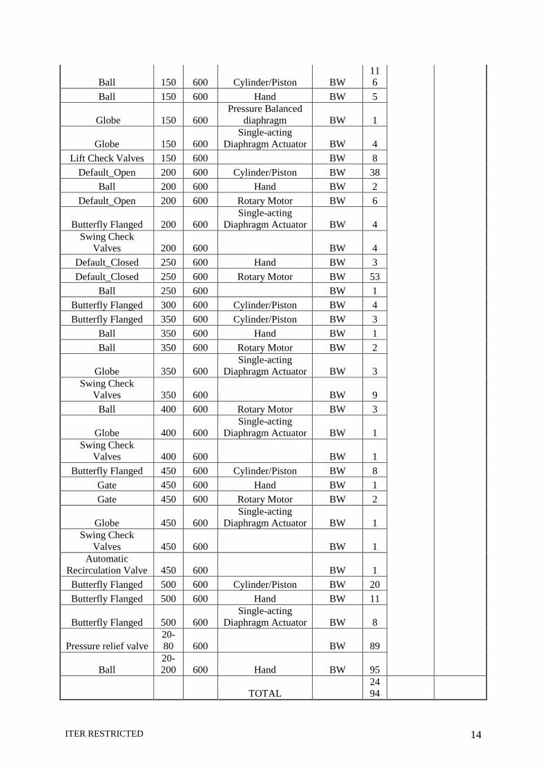
Ball 150 600 Cylinder/Piston BW 116
Ball 150 600 Hand BW 5
Globe 150 600 Pressure Balanced
diaphragm BW 1
Globe 150 600 Single-acting
Diaphragm Actuator BW 4 Lift Check Valves 150 600 BW 8
Default_Open 200 600 Cylinder/Piston BW 38 Ball 200 600 Hand BW 2
Default_Open 200 600 Rotary Motor BW 6
Butterfly Flanged 200 600 Single-acting
Diaphragm Actuator BW 4 Swing Check
Valves 200 600 BW 4 Default_Closed 250 600 Hand BW 3 Default_Closed 250 600 Rotary Motor BW 53
Ball 250 600 BW 1 Butterfly Flanged 300 600 Cylinder/Piston BW 4 Butterfly Flanged 350 600 Cylinder/Piston BW 3
Ball 350 600 Hand BW 1 Ball 350 600 Rotary Motor BW 2
Globe 350 600 Single-acting
Diaphragm Actuator BW 3 Swing Check
Valves 350 600 BW 9 Ball 400 600 Rotary Motor BW 3
Globe 400 600 Single-acting
Diaphragm Actuator BW 1 Swing Check
Valves 400 600 BW 1 Butterfly Flanged 450 600 Cylinder/Piston BW 8
Gate 450 600 Hand BW 1 Gate 450 600 Rotary Motor BW 2
Globe 450 600 Single-acting
Diaphragm Actuator BW 1 Swing Check
Valves 450 600 BW 1 Automatic
Recirculation Valve 450 600 BW 1 Butterfly Flanged 500 600 Cylinder/Piston BW 20 Butterfly Flanged 500 600 Hand BW 11
Butterfly Flanged 500 600 Single-acting
Diaphragm Actuator BW 8
Pressure relief valve 20-80 600 BW 89
Ball 20-200 600 Hand BW 95
TOTAL 2494
ITER RESTRICTED 15
ITER RESTRICTED 16
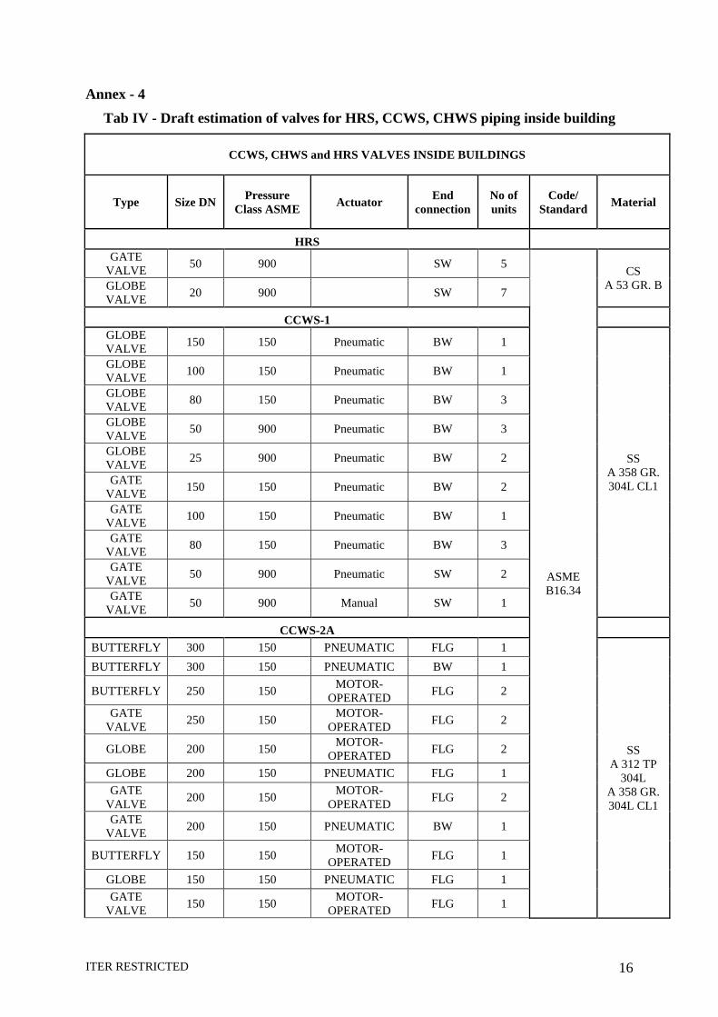
Annex - 4 Tab IV - Draft estimation of valves for HRS, CCWS, CHWS piping inside building
CCWS, CHWS and HRS VALVES INSIDE BUILDINGS
Type Size DN Pressure Class ASME Actuator End
connection No of units
Code/ Standard Material
HRS GATE
VALVE 50 900 SW 5
ASME B16.34
CS A 53 GR. B GLOBE
VALVE 20 900 SW 7
CCWS-1 GLOBE VALVE 150 150 Pneumatic BW 1
SS A 358 GR. 304L CL1
GLOBE VALVE 100 150 Pneumatic BW 1
GLOBE VALVE 80 150 Pneumatic BW 3
GLOBE VALVE 50 900 Pneumatic BW 3
GLOBE VALVE 25 900 Pneumatic BW 2
GATE VALVE 150 150 Pneumatic BW 2
GATE VALVE 100 150 Pneumatic BW 1
GATE VALVE 80 150 Pneumatic BW 3
GATE VALVE 50 900 Pneumatic SW 2
GATE VALVE 50 900 Manual SW 1
CCWS-2A BUTTERFLY 300 150 PNEUMATIC FLG 1
SS A 312 TP
304L A 358 GR. 304L CL1
BUTTERFLY 300 150 PNEUMATIC BW 1
BUTTERFLY 250 150 MOTOR-OPERATED FLG 2
GATE VALVE 250 150 MOTOR-
OPERATED FLG 2
GLOBE 200 150 MOTOR-OPERATED FLG 2
GLOBE 200 150 PNEUMATIC FLG 1 GATE
VALVE 200 150 MOTOR-OPERATED FLG 2
GATE VALVE 200 150 PNEUMATIC BW 1
BUTTERFLY 150 150 MOTOR-OPERATED FLG 1
GLOBE 150 150 PNEUMATIC FLG 1 GATE
VALVE 150 150 MOTOR-OPERATED FLG 1
ITER RESTRICTED 17
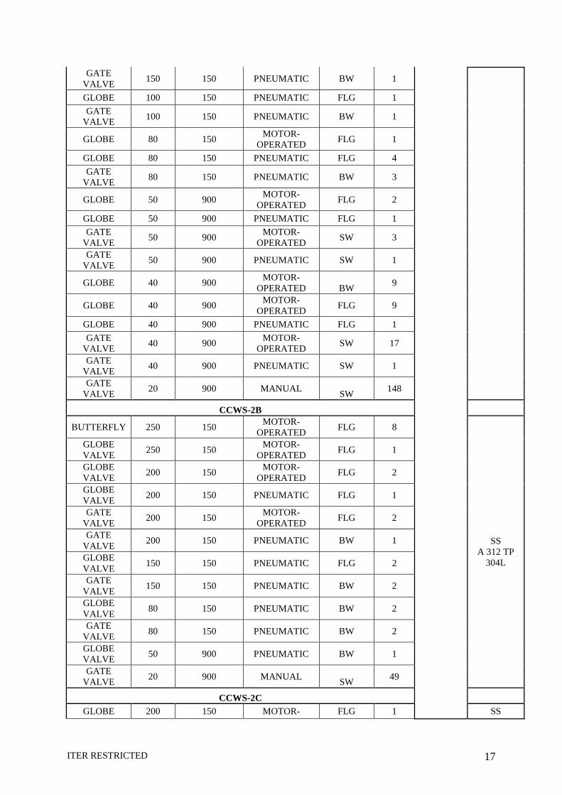
GATE VALVE 150 150 PNEUMATIC BW 1
GLOBE 100 150 PNEUMATIC FLG 1 GATE
VALVE 100 150 PNEUMATIC BW 1
GLOBE 80 150 MOTOR-OPERATED FLG 1
GLOBE 80 150 PNEUMATIC FLG 4 GATE
VALVE 80 150 PNEUMATIC BW 3
GLOBE 50 900 MOTOR-OPERATED FLG 2
GLOBE 50 900 PNEUMATIC FLG 1 GATE
VALVE 50 900 MOTOR-OPERATED SW 3
GATE VALVE 50 900 PNEUMATIC SW 1
GLOBE 40 900 MOTOR-OPERATED BW 9
GLOBE 40 900 MOTOR-OPERATED FLG 9
GLOBE 40 900 PNEUMATIC FLG 1 GATE
VALVE 40 900 MOTOR-OPERATED SW 17
GATE VALVE 40 900 PNEUMATIC SW 1
GATE VALVE 20 900 MANUAL SW 148
CCWS-2B
BUTTERFLY 250 150 MOTOR-OPERATED FLG 8
SS A 312 TP
304L
GLOBE VALVE 250 150 MOTOR-
OPERATED FLG 1
GLOBE VALVE 200 150 MOTOR-
OPERATED FLG 2
GLOBE VALVE 200 150 PNEUMATIC FLG 1
GATE VALVE 200 150 MOTOR-
OPERATED FLG 2
GATE VALVE 200 150 PNEUMATIC BW 1
GLOBE VALVE 150 150 PNEUMATIC FLG 2
GATE VALVE 150 150 PNEUMATIC BW 2
GLOBE VALVE 80 150 PNEUMATIC BW 2
GATE VALVE 80 150 PNEUMATIC BW 2
GLOBE VALVE 50 900 PNEUMATIC BW 1
GATE VALVE 20 900 MANUAL SW 49
CCWS-2C GLOBE 200 150 MOTOR- FLG 1 SS
ITER RESTRICTED 18
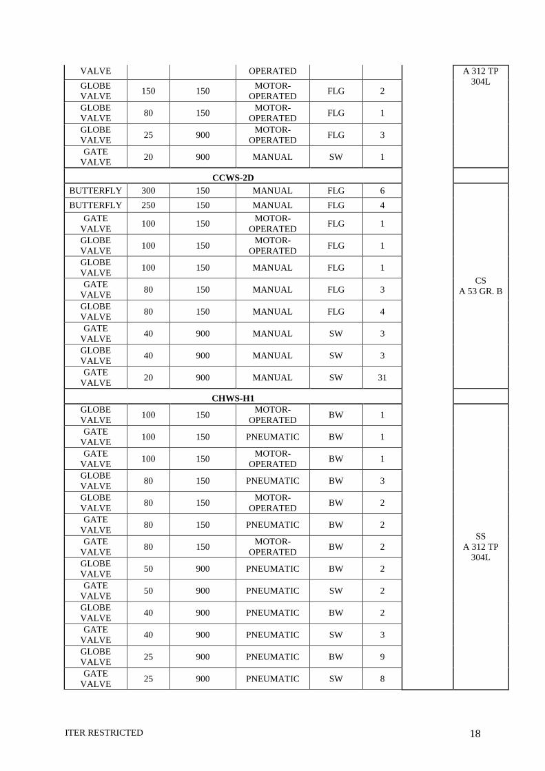
VALVE OPERATED A 312 TP 304L GLOBE
VALVE 150 150 MOTOR-OPERATED FLG 2
GLOBE VALVE 80 150 MOTOR-
OPERATED FLG 1
GLOBE VALVE 25 900 MOTOR-
OPERATED FLG 3
GATE VALVE 20 900 MANUAL SW 1
CCWS-2D BUTTERFLY 300 150 MANUAL FLG 6
CS A 53 GR. B
BUTTERFLY 250 150 MANUAL FLG 4 GATE
VALVE 100 150 MOTOR-OPERATED FLG 1
GLOBE VALVE 100 150 MOTOR-
OPERATED FLG 1
GLOBE VALVE 100 150 MANUAL FLG 1
GATE VALVE 80 150 MANUAL FLG 3
GLOBE VALVE 80 150 MANUAL FLG 4
GATE VALVE 40 900 MANUAL SW 3
GLOBE VALVE 40 900 MANUAL SW 3
GATE VALVE 20 900 MANUAL SW 31
CHWS-H1 GLOBE VALVE 100 150 MOTOR-
OPERATED BW 1
SS A 312 TP
304L
GATE VALVE 100 150 PNEUMATIC BW 1
GATE VALVE 100 150 MOTOR-
OPERATED BW 1
GLOBE VALVE 80 150 PNEUMATIC BW 3
GLOBE VALVE 80 150 MOTOR-
OPERATED BW 2
GATE VALVE 80 150 PNEUMATIC BW 2
GATE VALVE 80 150 MOTOR-
OPERATED BW 2
GLOBE VALVE 50 900 PNEUMATIC BW 2
GATE VALVE 50 900 PNEUMATIC SW 2
GLOBE VALVE 40 900 PNEUMATIC BW 2
GATE VALVE 40 900 PNEUMATIC SW 3
GLOBE VALVE 25 900 PNEUMATIC BW 9
GATE VALVE 25 900 PNEUMATIC SW 8
ITER RESTRICTED 19
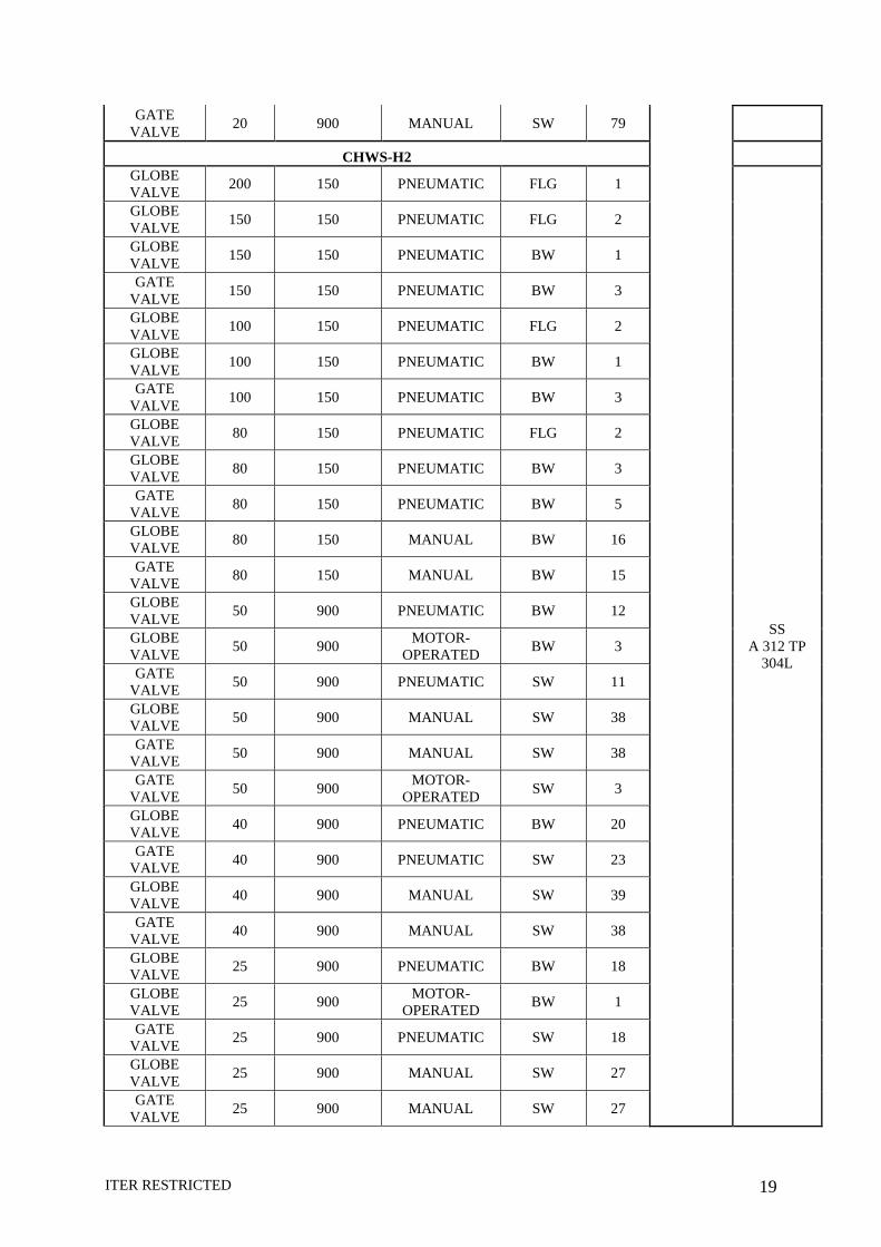
GATE VALVE 20 900 MANUAL SW 79
CHWS-H2 GLOBE VALVE 200 150 PNEUMATIC FLG 1
SS A 312 TP
304L
GLOBE VALVE 150 150 PNEUMATIC FLG 2
GLOBE VALVE 150 150 PNEUMATIC BW 1
GATE VALVE 150 150 PNEUMATIC BW 3
GLOBE VALVE 100 150 PNEUMATIC FLG 2
GLOBE VALVE 100 150 PNEUMATIC BW 1
GATE VALVE 100 150 PNEUMATIC BW 3
GLOBE VALVE 80 150 PNEUMATIC FLG 2
GLOBE VALVE 80 150 PNEUMATIC BW 3
GATE VALVE 80 150 PNEUMATIC BW 5
GLOBE VALVE 80 150 MANUAL BW 16
GATE VALVE 80 150 MANUAL BW 15
GLOBE VALVE 50 900 PNEUMATIC BW 12
GLOBE VALVE 50 900 MOTOR-
OPERATED BW 3
GATE VALVE 50 900 PNEUMATIC SW 11
GLOBE VALVE 50 900 MANUAL SW 38
GATE VALVE 50 900 MANUAL SW 38
GATE VALVE 50 900 MOTOR-
OPERATED SW 3
GLOBE VALVE 40 900 PNEUMATIC BW 20
GATE VALVE 40 900 PNEUMATIC SW 23
GLOBE VALVE 40 900 MANUAL SW 39
GATE VALVE 40 900 MANUAL SW 38
GLOBE VALVE 25 900 PNEUMATIC BW 18
GLOBE VALVE 25 900 MOTOR-
OPERATED BW 1
GATE VALVE 25 900 PNEUMATIC SW 18
GLOBE VALVE 25 900 MANUAL SW 27
GATE VALVE 25 900 MANUAL SW 27
ITER RESTRICTED 20
GATE VALVE 25 900 MOTOR-
OPERATED SW 1
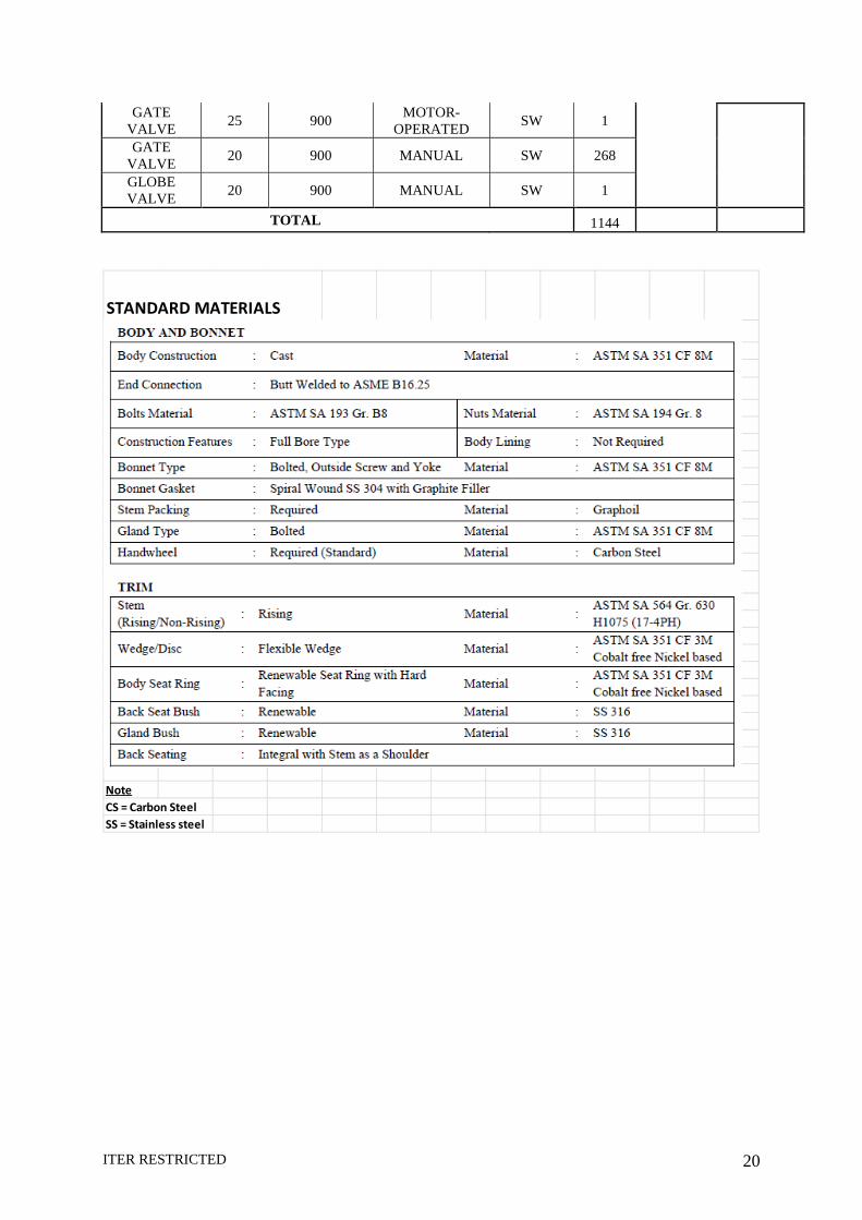
GATE VALVE 20 900 MANUAL SW 268
GLOBE VALVE 20 900 MANUAL SW 1
TOTAL 1144
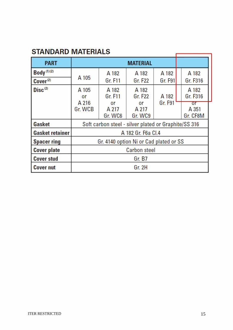
STANDARD MATERIALS
NoteCS = Carbon SteelSS = Stainless steel