control and navigation framework for quadrotor...
TRANSCRIPT

J Intell Robot SystDOI 10.1007/s10846-012-9789-z
Control and Navigation Framework for QuadrotorHelicopters
Amr Nagaty · Sajad Saeedi · Carl Thibault ·Mae Seto · Howard Li
Received: 20 September 2012 / Accepted: 20 September 2012© Springer Science+Business Media Dordrecht 2012
Abstract This paper presents the development ofa nonlinear quadrotor simulation framework to-gether with a nonlinear controller. The quadrotorstabilization and navigation problems are tack-led using a nested loops control architecture. Anonlinear Backstepping controller is implementedfor the inner stabilization loop. It asymptoticallytracks reference attitude, altitude and headingtrajectories. The outer loop controller generatesthe reference trajectories for the inner loop con-troller to reach the desired waypoint. To ensureboundedness of the reference trajectories, a PD
A. Nagaty (B) · S. Saeedi · C. Thibault · H. LiCOllaboration Based Robotics and Automation(COBRA) Laboratory, Department of Electrical andComputer Engineering, University of New Brunswick,Fredericton, New Brunswick, Canadae-mail: [email protected]:http://www.unb.ca/cobra
S. Saeedie-mail: [email protected]
C. Thibaulte-mail: [email protected]
H. Lie-mail: [email protected]
M. SetoDepartment of Mechanical Engineering,University of New Brunswick, Fredericton,New Brunswick, Canadae-mail: [email protected]
controller with a saturation function is used forthe outer loop. Due to the complexity involved incontroller development and testing, a simulationframework has been developed. It is based onthe Gazebo 3D robotics simulator and the OpenDynamics Engine (ODE) library. The frameworkcan effectively facilitate the development and val-idation of controllers. It has been released and isavailable at Gazebo quadrotor simulator (2012).
Keywords Quadrotor · Nonlinear control ·Backstepping · Navigation · Simulationframework · Gazebo · Open dynamics engine
1 Introduction
Unmanned aerial vehicles (UAVs) have becomeincreasingly popular for military and commercialapplications. The market demand for UAVs arisesfrom low manufacturing and operational costs ascompared to their manned counterparts. UAVsare mostly used for surveillance, inspection anddata acquisition. Their potential applications in-clude border patrol, search and rescue, wildfiremonitoring, traffic monitoring and land surveys.Most of the previously mentioned applicationsrequire hovering and vertical takeoff and landing(VTOL) capabilities. Generally, fixed-wing air-crafts are unable to perform VTOL and sufferfrom maneuverability constraints. Conventional

J Intell Robot Syst
helicopters are capable of hovering and VTOLbut are dynamically and structurally complex,expensive and hard to control [2]. Quadrotorhelicopters are becoming more favorable thanconventional helicopters as they are mechanicallysimpler and easier to control. Still, quadrotor con-trol is a challenging problem because of the in-herent system nonlinearities and cross couplingsdue to the gyroscopic moments and underactua-tion [3].
Different control methods have been recentlyapplied to tackle the quadrotor’s stability prob-lem. PID and LQ control methods have beenreported to successfully stabilize the quadrotor’sattitude around hover position in the presence ofminor disturbances [3]. Later, the same authorsapplied backstepping and sliding mode nonlinearcontrol methods and reported improved stabilityin the presence of relatively high perturbations [4].In [5], feedback linearization controller was com-bined with linear H∞ controller to robustify thecontrol law. Integral sliding mode and reinforce-ment learning methods were applied in [6] foraltitude control. The attractive cascaded-systemsstructure of the quadrotor’s model suggests theapplication of the Backstepping approach [7].It has been used several times in literature forquadrotor stabilization. In [8], the quadrotor sys-tem was divided into three interconnected subsys-tems: under-actuated, fully actuated and propellersubsystems. Backstepping algorithm was appliedrecursively until the whole system was stabilized.In [9], a hybrid Backstepping technique and theFernet-Serret Theory were applied to improve thedisturbance rejection capability. An integral termin the tracking error was incorporated to eliminatesteady state error.
The complexity correlated to the design ofquadrotor controllers sets up the necessity for areliable simulation framework [10]. A well de-signed and tuned simulation can effectively reducethe developing and testing time and cost for con-trollers. The major requirements in a simulationframework are:
• Accurate mathematical model of quadrotors• Ease of control system development and testing• Good quality rendering• Simulated set of sensors
Due to the overhead involved in quadrotor simu-lator development, most researchers tend to onlyrely on numerical simulations without visualiza-tion. On the other hand, commercial solutions aregenerally expensive such as the RotorLib heli-copter simulator developed by RTDynamics [11].Some open source solutions are available, how-ever they lack some of the previous requirements.JSBSim is an open source nonlinear flight dynam-ics simulator that lacks rendering [12]. FlightGearis an open flight simulator framework, based onJSBSim, with a sophisticated visualizer [13]. How-ever, it lacks simulated sensors feedback. For theUAV’s branch of robotics, open source simula-tor development is lagging. While in the case ofground robots, more complete frameworks havebeen developed and thoroughly tested. In par-ticular, we focus on the Player / Stage / Gazeboframework [14]. It is the most complete simulationframework with respect to the previously men-tioned requirements. It is capable of simulatingrobots, sensors and objects in a three-dimensionalworld. In addition, it generates realistic sensorfeedback that can be used for testing not onlycontrollers but autonomous behaviors as well. Itis based on accurate simulation of rigid body dy-namics using the Open Dynamics Engine (ODE)library [15].
In this paper, we tackle the stabilization andnavigation problems of a quadrotor. A nonlin-ear model is derived and used for controller de-sign. Motivated by the structure of the model, anested loops control architecture is used. For theinner loop, a Backstepping tracking controller isdesigned for attitude, altitude and heading. Forthe outer loop, a PD controller with a satura-tion function is implemented. It achieves waypointnavigation while ensuring the boundedness of thereference trajectories. We build upon an existingsimulator to develop a simulation framework thatmeets the previous requirements [16]. It is basedon the Gazebo 3D robotics simulator, the ODElibrary and the nonlinear quadrotor model.
This paper is organized as follows: The quadro-tor kinematics and dynamics models are derivedin Section 2. In Section 3, we present the statespace model and the navigation and stabilizationcontrollers. The stability of the proposed con-troller is investigated in Section 4. The developed
J Intell Robot Syst
simulation framework is introduced in Section 5.Simulation results are presented in Section 6 toshow the effectiveness of the proposed controller.Finally, the paper is concluded in Section 7.
2 Quadrotor Model
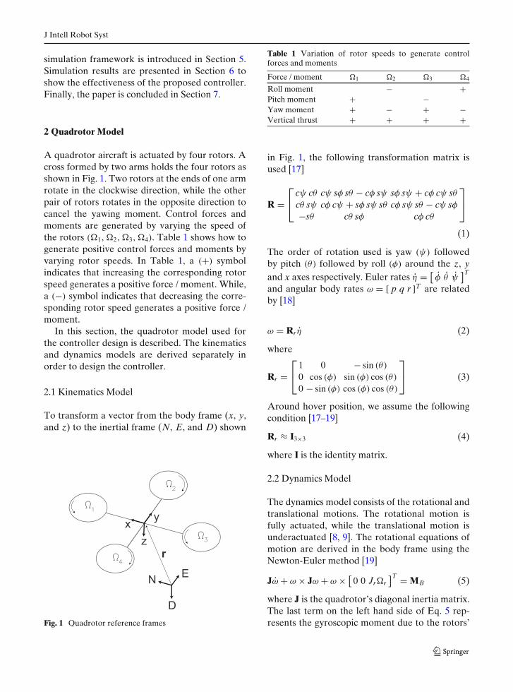
A quadrotor aircraft is actuated by four rotors. Across formed by two arms holds the four rotors asshown in Fig. 1. Two rotors at the ends of one armrotate in the clockwise direction, while the otherpair of rotors rotates in the opposite direction tocancel the yawing moment. Control forces andmoments are generated by varying the speed ofthe rotors (�1, �2, �3, �4). Table 1 shows how togenerate positive control forces and moments byvarying rotor speeds. In Table 1, a (+) symbolindicates that increasing the corresponding rotorspeed generates a positive force / moment. While,a (−) symbol indicates that decreasing the corre-sponding rotor speed generates a positive force /moment.
In this section, the quadrotor model used forthe controller design is described. The kinematicsand dynamics models are derived separately inorder to design the controller.
2.1 Kinematics Model
To transform a vector from the body frame (x, y,and z) to the inertial frame (N, E, and D) shown
Fig. 1 Quadrotor reference frames
Table 1 Variation of rotor speeds to generate controlforces and moments
Force / moment �1 �2 �3 �4
Roll moment − +Pitch moment + −Yaw moment + − + −Vertical thrust + + + +
in Fig. 1, the following transformation matrix isused [17]
R =⎡⎣
cψ cθ cψ sφ sθ − cφ sψ sφ sψ + cφ cψ sθcθ sψ cφ cψ + sφ sψ sθ cφ sψ sθ − cψ sφ−sθ cθ sφ cφ cθ
⎤⎦
(1)
The order of rotation used is yaw (ψ) followedby pitch (θ) followed by roll (φ) around the z, yand x axes respectively. Euler rates η = [
φ θ ψ]T
and angular body rates ω = [ p q r ]T are relatedby [18]
ω = Rrη (2)
where
Rr =⎡⎣
1 0 − sin (θ)
0 cos (φ) sin (φ) cos (θ)
0 − sin (φ) cos (φ) cos (θ)
⎤⎦ (3)
Around hover position, we assume the followingcondition [17–19]
Rr ≈ I3×3 (4)
where I is the identity matrix.
2.2 Dynamics Model
The dynamics model consists of the rotational andtranslational motions. The rotational motion isfully actuated, while the translational motion isunderactuated [8, 9]. The rotational equations ofmotion are derived in the body frame using theNewton-Euler method [19]
Jω + ω × Jω + ω × [0 0 Jr�r
]T = MB (5)
where J is the quadrotor’s diagonal inertia matrix.The last term on the left hand side of Eq. 5 rep-resents the gyroscopic moment due to the rotors’

J Intell Robot Syst
inertia Jr and relative speed �r = −�1 + �2 −�3 + �4. The aerodynamic forces and momentsproduced by the ith rotor are directly proportionalto the square of the rotor’s speed
Fi = kF�2i
Mi = kM�2i (6)
where kF and kM are the aerodynamic forceand moment constants respectively. The momentsacting on the quadrotor in the body frame aregiven by
MB =⎡⎣
l · kF(−�2
2 + �24
)l · kF
(�2
1 − �23
)kM
(�2
1 − �22 + �2
3 − �24
)
⎤⎦ (7)
where l is the moment arm, the distance fromthe axis of rotation of the rotors to the center ofthe quadrotor. The translational equations of mo-tion are derived in a North-East-Down navigationframe using Newton’s second law
mr = [0 0 mg
]T + RFB (8)
where r = [x y z
]Tis the quadrotor’s position in
the navigation frame, m is the quadrotor’s massand g is the acceleration due to gravity. The non-gravitational forces acting on the quadrotor in thebody frame are given by
FB =⎡⎣
00
−kF(�2
1 + �22 + �2
3 + �24
)
⎤⎦ (9)
3 Controller Design
Because of the quadrotor dynamics, a nested loopscontrol strategy is appropriate [8]. From Eqs. 5
and 8, it can be seen that the rotational motion isindependent of the translational motion, while theopposite is not true. Thus, an inner control loopcan be designed to ensure asymptotic tracking ofdesired attitude, altitude and heading. While, anouter control loop can be designed for quadrotornavigation, as shown in Fig. 2. In this section,the quadrotor’s state space model is presented forcontroller design. A PD controller is designed forthe outer loop, while a Backstepping controller isdesigned for the inner loop.
3.1 State Space Model
The state vector is defined as [4]
X = [φ φ θ θ ψ ψ z z x x y y
](10)
The control input vector is defined as
U = [U1 U2 U3 U4
](11)
where
U1 = kF(�2
1 + �22 + �2
3 + �24
)
U2 = kF(−�2
2 + �24
)
U3 = kF(�2
1 − �23
)
U4 = kM(�2
1 − �22 + �2
3 − �24
)(12)
The state space model is given by
X = f (X, U) (13)
Fig. 2 Controlarchitecture
QuadrotorModel
AttitudeController
PositionController
DesiredPosition
HeadingController
AltitudeController
xd
yd
zd
d U2
U3
RotorsSpeed
Calculation
U4
U1
1 4
z
J Intell Robot Syst
where
f(X,U)=
⎡⎢⎢⎢⎢⎢⎢⎢⎢⎢⎢⎢⎢⎢⎢⎢⎢⎢⎢⎢⎢⎢⎢⎢⎣
x2
x4x6a1 + x4�ra2 + b 1U2
x4
x2x6a3 + x2�ra4 + b 2U3
x6
x2x4a5 + b 3U4
x8
g − U1
mcos x1 cos x3
x10
−U1
m(sin x1 sin x5 + cos x1 sin x3 cos x5)
x12U1
m(sin x1 cos x5 − cos x1 sin x3 sin x5)
⎤⎥⎥⎥⎥⎥⎥⎥⎥⎥⎥⎥⎥⎥⎥⎥⎥⎥⎥⎥⎥⎥⎥⎥⎦
(14)
a1 =(Iyy − Izz
)
Ixx
a2 = Jr
Ixx
a3 = (Izz − Ixx)
Iyy
a4 = Jr
Iyy
a5 =(Ixx − Iyy
)Izz
b 1 = lIxx
b 2 = lIyy
b 3 = 1Izz
(15)
3.2 Outer Control Loop
For position control, a PD controller with a sat-uration function is implemented to generate thereference roll φd and pitch θd. The referenceangles are tracked by the inner loop controller[19]. Based on the desired waypoint, the position
controller calculates the desired accelerations xd
and yd
xd = kp (xref − x) + kd (xref − x)
yd = kp (yref − y) + kd (yref − y) (16)
where (xd, yd) is the desired waypoint, (xd, yd) isthe desired velocity and kp and kd are the propor-tional and derivative controller gains respectively.The reference roll and pitch angles can be solvedfor using the desired accelerations
− U1
m[sin φd sin ψ + cos φd sin θd cos ψ] = xd
U1
m[sin φd cos ψ − cos φd sin θd sin ψ] = yd (17)
Using the small angle assumption around thehover position, the previous equations can besimplified
− U1
m[φd sin ψ + θd cos ψ] = xd
U1
m[φd cos ψ − θd sin ψ] = yd (18)
[− sin ψ − cos ψ
cos ψ − sin ψ
] [φd
θd
]= m
U1
[xd
yd
](19)
which has a closed form solution for φd and θd. Asaturation function is needed to ensure that thereference roll and pitch angles are within specifiedlimits
φd = sat(φd)
θd = sat(θd) (20)
where
sat(v) ={
v ‖v‖ ≤ vmax
sign(v)vmax ‖v‖ > vmax(21)
such that
sign(v) ={
−1 v < 01 v ≥ 0
(22)
3.3 Inner Control Loop
The attitude, heading and altitude controllers (seeFig. 2) are derived using the Backstepping ap-proach. The idea behind Backstepping is to designa controller recursively by considering some of the

J Intell Robot Syst
state variables as virtual controls. Then, interme-diate stabilizing control laws are designed for thevirtual controls [20]. At the last step, the actualcontrol input is used to stabilize the whole system.The design procedure is systematic. Therefore, weonly present the design procedure for roll control.Pitch, yaw and altitude controllers can be derivedsimilarly. For clarity of presentation, the nonlinearsystem under investigation is extracted from thestate space model derived in Eq. 14.
x1 = x2
x2 = x4x6a1 + x4�ra2 + b 1U2 (23)
which is in the strict feedback form
x1 = x2
x2 = f (X) + b 1U2 (24)
The backstepping procedure transforms the closedloop system to the following coordinates
z1 = x1 − x1d
z2 = x2 − α1 (25)
Fig. 4 Simulation environment
where α1 is the virtual control input and x1 − x1d isthe roll tracking error. We introduce the followingLyapunov function
V1 = 12
z21 (26)
Fig. 3 Simulator framework
J Intell Robot Syst
whose derivative along the system trajectories isgiven by
V1 = z1z1
= z1 (z2 + α1 − x1d) (27)
The virtual control input can be chosen as
α1 = −c1z1 + x1d (28)
such that
V1 = −c1z21 + z1z2 (29)
We augment the previous Lyapunov function inthe following way
V2 = 12
z21 + 1
2z2
2 (30)
The derivative along system trajectories isgiven by
V2 = z1z1 + z2z2
= −c1z21 + z1z2 + z2 (x2 − α1)
= −c1z21 + z2 (z1 + f (X) + b 1U2 − α1) (31)
Now, the actual control input is at our disposal forthe overall roll control
U2 = 1b 1
(−c2z2 − z1 − f (X) + α1) (32)
such that
V2 = −c1z21 − c2z2
2 (33)
0 0.5 1 1.5 2 2.5 3 3.5 40
5
10
15
20
Rol
l in
degr
ees
0 0.5 1 1.5 2 2.5 3 3.5 40
5
10
15
20
Pitc
h in
deg
rees
0 0.5 1 1.5 2 2.5 3 3.5 40
5
10
15
20
Yaw
in d
egre
es
0 0.5 1 1.5 2 2.5 3 3.5 4−1.8
−1.6
−1.4
−1.2
−1
Alti
tude
in m
eter
s
Time in Seconds
Response
Reference
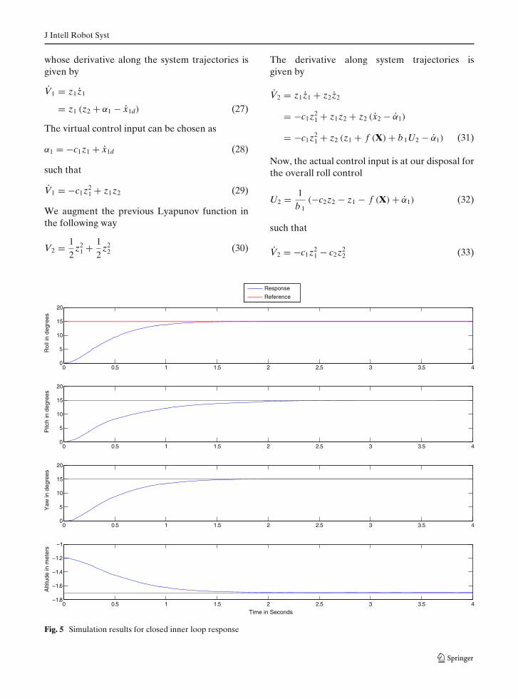
Fig. 5 Simulation results for closed inner loop response

J Intell Robot Syst
4 Stability Analysis
In this section, the stability and performance ofthe proposed inner loop controller are analyzedusing Lyapunov’s stability theorem [7, 20]. Theclosed loop system is analyzed in the transformedcoordinate system
[z1
z2
]=
[−c1 1−1 −c2
] [z1
z2
](34)
The closed loop system is an autonomous systemin the error coordinates. Stability can be analyzedusing LaSalle invariance theorem. Recall Eq. 30,it is clear that the Lyapunov function is positivedefinite, decresent and radially unbounded. Re-call Eq. 33, the Lie derivative of the Lyapunovfunction is negative definite. According to Lya-punov’s second method, the closed loop system is
Globally Asymptotically Stable (GAS). Also, thesystem trajectories z1 and z2 are bounded. FromEq. 28, the boundedness of the virtual input α1 canbe deduced. From Eq. 32, the boundedness of theactual control input can be deduced. Moreover,the Lyapunov function has a minimum dissipationrate
V2 (Z) ≤ −σ V2 (Z) (35)
where c1 ≥ 12 , c2 ≥ 1
2 and Z = [z1 z2
]. Therefore,
the closed loop system is Globally ExponentiallyStable (GES) with bounded control input as longas Eq. 4 holds. Next, a bound on the transienttracking error is derived in terms of the controllerdesign parameters. From Eq. 33, the dissipationrate of the Lyapunov function satisfies
V2 (Z) ≤ −c1z21 (36)
0 0.5 1 1.5 2 2.5 3 3.5 4−0.05
0
0.05
0. 1
0.15
U2
0 0.5 1 1.5 2 2.5 3 3.5 4−0.1
0
0.1
0.2
0.3
U3
0 0.5 1 1.5 2 2.5 3 3.5 4−0.05
0
0.05
U4
0 0.5 1 1.5 2 2.5 3 3.5 4−10
−9
−8
−7
−6
U1
Time in Seconds
Fig. 6 Simulation results for actuation inputs
J Intell Robot Syst
The L2 norm of the transient tracking error isgiven by
||z1||22 =∫ ∞
0|z1 (τ )|2 dτ
≤ − 1c1
∫ ∞
0V2 ((Z (τ )) dτ
≤ 1c1
[V2 (Z (0)) − V2 (Z (∞))]
≤ 1c1
V2 (Z (0))
(37)
5 Simulation Framework
A simulation framework for testing the quadro-tor’s stabilization and navigation controllers isdeveloped. It is based on the open-source 3D ro-botics simulator Gazebo [14] and the ODE library[15]. The quadrotor dynamics model derived ear-
lier is implemented in the Gazebo simulator tocalculate the forces and moments acting on thevehicle. Using the Gazebo API interface, the de-rived forces and moments are input to the ODE.It solves the body’s equations of motion and sendsthe vehicle’s states back to Gazebo for visualiza-tion. The stabilization and navigation controllersare implemented directly in Gazebo such thatthey can use the vehicle’s states for feedbackand send the control commands to the dynamicsmodule. The simulator framework is shown inFig. 3. Gazebo offers plugins for different sensorpackages that can be mounted on the quadrotorto provide sensor feedback for higher levels ofautonomy. For example, the quadrotor can beequipped with onboard camera and laser sensorsto provide feedback for visual servoing and simul-taneous localization and mapping. Figure 4 showsa screen shot of the simulation environment wherethe quadrotor is equipped with additional sensors,camera and laser.
−20
24
68
10
−2
0
2
4
6
8
10−3.5
−3
−2.5
−2
−1.5
−1
−0.5
0
X in metersY in meters
Z in
met
ers
PathWaypoint
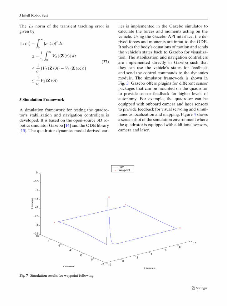
Fig. 7 Simulation results for waypoint following

J Intell Robot Syst
6 Simulation Results
In this section, simulation results for the inner andouter loop controllers are presented.
6.1 Inner Loop Results
Figure 5 shows the closed loop response of theroll, pitch, yaw and altitude to a step input. Thesteady state is reached within approximately 2 susing bounded control inputs as shown in Fig. 6.The Backstepping controller asymptotically regu-lates the roll, pitch, yaw and altitude despite of thecross couplings between them and the inherentnonlinearities.
6.2 Outer Loop Results
Figure 7 shows the waypoint navigation perfor-mance of the proposed controller; it shows take-
off, waypoint following and landing. Due to ourcoordinate system convention defined in Section 2,the altitude is negative in the upward direction.As shown in Fig. 7, the quadrotor is given fourwaypoints to follow at a desired altitude of 3 m.The quadrotor doesn’t have to exactly reach thewaypoint to advance to the next one, rather athreshold distance of 0.5 m is defined. The quadro-tor first ascends to the desired altitude and startsfollowing the programmed waypoints and finallydescends to the original altitude. Figure 8 showsthe reference roll and pitch angles generated bythe position controller to reach the desired way-points. Initially, the quadrotor is directly facingthe first waypoint. The position controller gener-ates negative reference pitch angles and regulatesthe roll angle to zero such that the quadrotormoves towards the first waypoint. Notice that theposition controller doesn’t maintain a negativepitch angle as it will cause the quadrotor’s linear
0 20 40 60 80 100 120−3
−2
−1
0
1
2
3
Rol
l in
degr
ees
0 20 40 60 80 100 120−2.5
−2
−1.5
−1
−0.5
0
0.5
1
1.5
2
Pitc
h in
deg
rees
Time in Second
Response
Reference
Fig. 8 Simulation results for position controller

J Intell Robot Syst
acceleration to increase rapidly and overshootthe desired waypoint. Rather, it produces a largeinitial acceleration and decelerates the quadrotorgradually untill it reaches the desired waypointat a low speed. At around 30 s, the quadrotor iswithin 0.5 m from the first waypoint and startsadvancing to the second one. As the quadrotorperforms the 90◦ turn, the position controller gen-erates reference roll angles to control the quadro-tor’s position as it pitches forward during the turn.At around 110 s, the quadrotor reaches its finalwaypoint and attitude is stabilized to zero.
7 Conclusion
In this paper, a simulation framework for quadro-tor stabilization and navigation is presented. Anonlinear quadrotor model is presented and usedfor controller design and simulator development.Based on the structure of the developed model,a nested loops control architecture is adoptedfor stabilization and navigation. The inner loopcontrol system is designed using the nonlinearBackstepping method to asymptotically track ref-erence attitude, altitude and heading trajectories.Stability of the controller is analyzed in termsof asymptotic tracking, transient tracking errorand boundedness of control inputs. For positioncontrol, a PD controller with a saturation func-tion is implemented to ensure boundedness ofthe generated reference trajectories. A simulationframework is developed to facilitate controller de-velopment and testing. The framework is based ona nonlinear quadrotor model implemented in theGazebo robotics simulator using the ODE library.The framework provides rendering capabilitiesand access to a set of simulated sensors that canbe used for testing autonomous behaviors. Simu-lation results demonstrate the effectiveness of theproposed controller and simulator. Future workincludes further improvement in the developedsimulation framework and integration with thewell-known middleware, Robot Operating System(ROS) [21]. The developed simulation frameworkhas been released and is available at [1].
Acknowledgements The authors would like to acknowl-edge the following funding agencies: Natural Sciences and
Engineering Research Council of Canada, Canada Foun-dation for Innovation, Defence Research and Develop-ment Canada, and New Brunswick Innovation Foundation.
References
1. Gazebo quadrotor simulator. Available online http://sourceforge.net/projects/gazebo-quad-sim. Accessed10 Mar 2012
2. Hoffmann, G., Waslander, S., Vitus, M., Huang, H.,Gillula, J., Pradeep, V., Tomlin, C.: Stanford test-bed of autonomous rotorcraft for multi-agent control.In: IEEE/RSJ International Conference on IntelligentRobots and Systems, 2009. IROS 2009, pp. 404–405(2009)
3. Bouabdallah, S., Noth, A., Siegwart, R.: Pid vs lqcontrol techniques applied to an indoor micro quadro-tor. In: 2004 IEEE/RSJ International Conference onIntelligent Robots and Systems, 2004, (IROS 2004),Proceedings, vol. 3, pp. 2451–2456. 2 Sept – Oct(2004)
4. Bouabdallah, S., Siegwart, R.: Backstepping andsliding-mode techniques applied to an indoor microquadrotor. In: Proceedings of the 2005 IEEE Inter-national Conference on Robotics and Automation,Robotics and Automation 2005. ICRA 2005, pp. 2247–2252 (2005)
5. Mokhtari, A., Benallegue, A., Daachi, B.: Robustfeedback linearization and gh infin; controller for aquadrotor unmanned aerial vehicle. In: 2005 IEEE/RSJ International Conference on Intelligent Ro-bots and Systems, 2005, (IROS 2005), pp. 1198–1203(2005)
6. Waslander, S., Hoffmann, G., Jang, J.S., Tomlin, C.:Multi-agent quadrotor testbed control design: inte-gral sliding mode vs. reinforcement learning. In: 2005IEEE/RSJ International Conference on Intelligent Ro-bots and Systems, 2005, (IROS 2005), pp. 3712–3717(2005)
7. Khalil, H.: Nonlinear Systems. Prentice Hall (2002)8. Madani, T., Benallegue, A.: Backstepping control for
a quadrotor helicopter. In: 2006 IEEE/RSJ Interna-tional Conference on Intelligent Robots and Systems,pp. 3255–3260 (2006)
9. Colorado, J., Barrientos, A., Martinez, A., Lafaverges,B., Valente, J.: Mini-quadrotor attitude control basedon hybrid backstepping amp; frenet-serret theory. In:2010 IEEE International Conference on Robotics andAutomation (ICRA), pp. 1617–1622 (2010)
10. Mancini, A., Cesetti, A., Iual, A., Frontoni, E.,Zingaretti, P., Longhi, S.: A framework for simulationand testing of uavs in cooperative scenarios. J. Intell.Robot. Syst. 54, 307–329 (2009)
11. Rotorlib: Available online http://www.rtdynamics.com.Accessed 10 Mar 2012
12. Jsbsim: Available online http://jsbsim.sourceforge.net.Accessed 10 Mar 2012
J Intell Robot Syst
13. Flightgear: Available online http://www.flightgear.org.Accessed 10 Mar 2012
14. Gazebo 3d Robotics Simulator: Available onlinehttp://playerstage.sourceforge.net/gazebo/gazebo.html.Accessed 10 Mar 2012
15. Open Dynamics Engine Library: Available onlinehttp://www.ode.org/. Accessed 10 Mar 2012
16. Gazebo Quad Sim: Available online http://sourceforge.net/projects/gazeboquadrotor. Accessed 10 Mar 2012
17. Lee, D., Jin Kim, H., Sastry, S.: Feedback linearizationvs. adaptive sliding mode control for a quadrotor heli-copter. Int. J. Control Autom. Syst. 7, 419–428 (2009)
18. Bouabdallah, S.: Design and control of quadrotors withapplication to autonomous flying. Ph.D. dissertation,Lausanne (2007)
19. Michael, N., Mellinger, D., Lindsey, Q., Kumar, V.:The grasp multiple micro-uav testbed. IEEE Robot.Autom. Mag. 17(3), 56–65 (2010)
20. Krstic, M., Kanellakopoulos, I., Kokotovic, P.: Non-linear and adaptive control design, ser. Adaptive andlearning systems for signal processing, communica-tions, and control. Wiley (1995)
21. Robot Operating System: Available online http://www.ros.org/. Accessed 10 Mar 2012