control valve testing compressed - …mactechaustralia.com.au/downloads/ventil/control valve...
TRANSCRIPT

w w w . v e n t i l . n l
CONTROL VALVE TESTING
The optimal functioning of the Control valve not only exists of sufficient body & seat tightness,
but more important, the total "performance" of the valve and its controls! For an accurate and
reliable working effect the valve body, actuator, positioner, regulators etc. most work in a strict
harmony!
WHY TESTING..!?
Control valves are the final control elements in the operation of a
continuously generating (petro) chemical process installation or power plant.
Therefore the, plant efficiency is directly affected by non-performance of the
valves, either in terms of output or in terms of reliability and availability.
Recent studies indicate that leaking or poor performing control valves only
can reduce a power plant’s output by up to 50 MW. While generally still 50-
60% of the fugitive emission of industrial installations comes from its (control)
valves, eliminating control valve problems alone can improve the heat rate of
power plants in the range of 2 - 5%.
The modern continuously generating petrochemical- or power plant requires
that the control valves
provide both control and shut-off functions. Not only this dual
role reduces capital expense, it also addresses the complexity
of many control algorithms. Providing tight shut-off and control
in one valve rather than two valves eliminates the need for two
sets of logics to be embedded into the control system. The
valves are also expected to maintain long term shut-off without
leaking. Nevertheless many of these valves must operate
under severe service conditions with high pressure and/or high
temperature applications.
RESULTS OF IMPROPER MAINTENANCE & TESTING:
√ Process controllability problems with the valve operating at lower openings.
√ Poor shut-off capability, i.e. leakage through the valve under closed conditions, because of adequate actuator
thrust, damage to the sealing surfaces caused by high velocities and improper calibration.
√ Premature trim and body erosion.
√ Poor dynamic response.

w w w . v e n t i l . n l
CONTROL VALVE TESTING
THE TYPICAL RESULTS OF CONTROL VALVE PROBLEMS ARE:
√ Longer start up time.
√ Loss in production capacity.
√ Frequent maintenance.
√ Occasional plant trips.
√ Safety and environmental concerns (penalties for high
risks or operations costs).
√ Collateral damage to other expensive plant equipment.
√ Lower unit availability and low flexibility.
Although plant designers threat them only as ‘necessary evils’, it is obvious that actuator-operated valves play a key
role in the process quality and reliability and extreme care must be taken to avoid costly premature failures possibly
resulting in substantial losses or plant shut-down. Besides the potential for improvement of reliability and efficiency,
correct valve repair and testing also removes a major obstacle for the plants to operate for longer intervals.

w w w . v e n t i l . n l
CONTROL VALVE TESTING
Ventil manufactures a wide range of test units for testing and (re)adjusting all sorts of Globe-, Camflex-,
and Waver type control valve according to the international test standards. The Ventil test units can be
used for;
√ SEAT LEAKAGE TESTING AND CLASSIFICATION
The seat leakage is tested with gas or liquid according to the international test standards. The most common
applied test standard is FCI 70-2. Control valves class I – IV and VI are tested with gas. Class V with liquid (see
schedule 1.2 and 1.3).
The seat leakage is measured on the in or ourlet
side by the digital, calibrated flow measuring
system. The leakage (displayed in ln/min, ln/h, scfh
or bubbles / min) is automatically compared with
the standardised allowed leakage, followed by
pass / fail signal.
√ BODY TESTING
New valves and valves which have gone through a
full reconditioning process need to be body’s
tested with liquid at 1.5 times the nominal working
pressure. Prior to the hydrostatic body or so called Shell test, the valve
is completely filled by tilting the clamp or by a ‘vacuum – filling’ system.
Visual inspection and/or a pressure decay method is used to proof the
body integrity.
√ STROKING THE TRIM
The optimal functioning of the Control valve not only exists of sufficient
body & seat tightness, but more important, the total ‘performance’ of
the valve and its controls!
The functionality of the controls is tested and adjusted according to the
manufacturers specification or specific process circumstances. The
Valve is operated to the open-/close position by operating the actuator
and/or positioner with external signals, usual 0 – 21 mA / 0-20 PSI / 0-
100 PSI. Specific software for digital positioners can be applied.

w w w . v e n t i l . n l
CONTROL VALVE TESTING
IMPORTANT FEATURES
Quick clamping
The most important feature of the Ventil test unit is the quick clamping system. A variety of features is available;
√ Horizontal (stem vert.), vertical (stem hor.) or tilting clamping system.
√ ½ - 86” / DN15 – 2200 mm.
√ 1 – 2000 ton’s.
√ Clamping on the inlet flange, both flanges or (proportional clamping) between the clamping tables.
Test- & operation systems
The standard test unit contains the following test systems;
√ Low pressure gas (compressed air) test system 0-10 bar / 145 PSI.
√ Seat leakage measuring system 0 – 1000 ln/min. / 2100 scfh.
√ Seat leakage measuring 0 – 50 bubbles / min.
√ 0 – 21 mA, 0-20 PSI (2 bar), 0-100 PSI (7 bar) for testing and setting the
controls.
A variety of additional low and high pressure gas and liquid test systems is
available on request.
Range, Set up and Configuration
Standard ½ – 10”, but any range in size, leak rate and pressure class can be accommodated on client
specification. Ventil only uses the best components and materials, designed for continues use and a long and
reliable working effect.
Horizontal, clamping on inlet flange only
Tilting. Vertical liquid filling and testing.
w w w . v e n t i l . n l
CONTROL VALVE TESTING
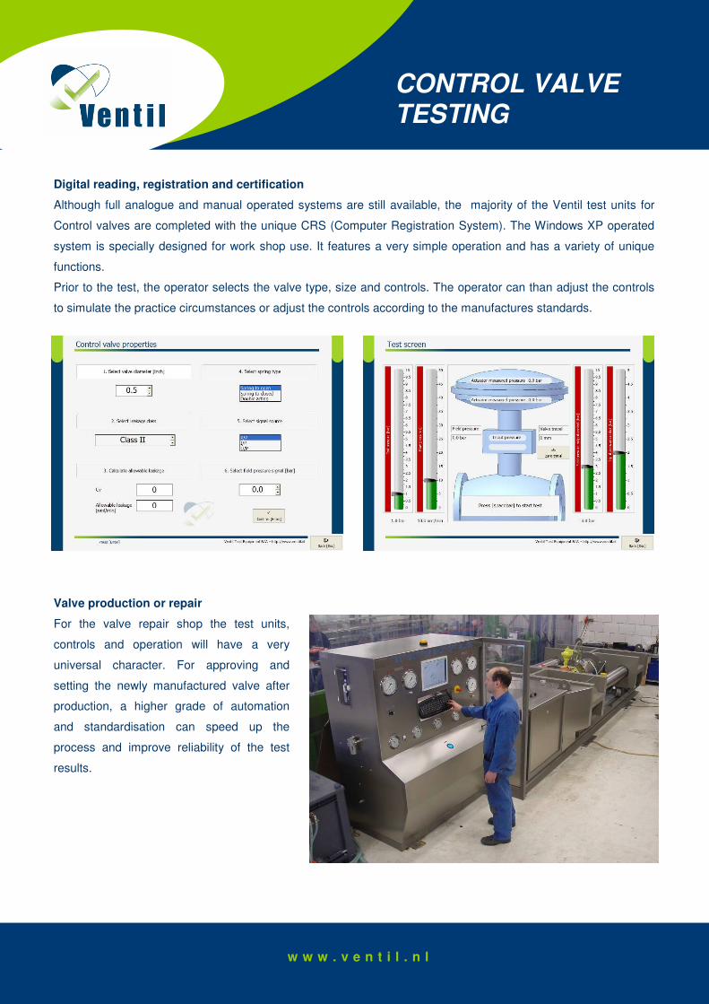
Digital reading, registration and certification
Although full analogue and manual operated systems are still available, the majority of the Ventil test units for
Control valves are completed with the unique CRS (Computer Registration System). The Windows XP operated
system is specially designed for work shop use. It features a very simple operation and has a variety of unique
functions.
Prior to the test, the operator selects the valve type, size and controls. The operator can than adjust the controls
to simulate the practice circumstances or adjust the controls according to the manufactures standards.
Valve production or repair
For the valve repair shop the test units,
controls and operation will have a very
universal character. For approving and
setting the newly manufactured valve after
production, a higher grade of automation
and standardisation can speed up the
process and improve reliability of the test
results.

w w w . v e n t i l . n l
CONTROL VALVE TESTING
AVPS
The AVPS system is a optional feature on all Control valve test units. The computer operated system enables you
to run a variety of test and accurately detect and measure the performance of the valve controls. Standard test
procedures are:
Dynamic scan
The typical test on a common diaphragm control valve is the automatic
dynamic scan which ramps the operational input signal from its minimum
operating point (normally 4 mA) to its maximum operating value (typically 20
mA), and then reverse the signal and ramp back to the starting point.
The signal will pause at the peak value and pause again at the minimum value
to allow the valve to stabilize before reversing the signal or ending the test.
Guidelines for selecting the ramp speed are selected in the software. During
the time that the signal is being controlled, the software collects data on the
active channels assigned; the input signal ramp and travel. The standard
graph on the screen offers clear information on what the typical valve should
indicate if it is in a good condition. The graph created from the test, plots the
input signal and valve travel, giving a picture of the overall valve performance.
The system documents the overall calibration, travel, linearity and ‘dynamic error band’.
B) Step test
The ‘step test’ is similar to the dynamic scan, but in
stead of a linear input signal the valve is now
opened and closed in a certain amount of pre-
programmed steps. For example 4 – 8 – 12 – 16 –
20 mA. On the screen the AVPS software program
draws graphics of the input signal (mA or
compressed air) and the reaction (output) of the
valve. This system is suitable for DA, NO and NC).
C) Dump test
With the ‘dump test’ the valve is opened or closed
within a minimum programmed setting. The maximum input signal is programmed and the reaction of the valve is
shown on the screen.

w w w . v e n t i l . n l
CONTROL VALVE TESTING
Schedule 1.1
Standardised test pressures for valves
BODY TEST PRESSURE (minimum)
SEAT TEST PRESSURE (minimum) RATING
bar PSI bar PSI
CLASS 150
29.4 427.5 21.6 313.5
CLASS 300
76.7 1110 56.2 814
CLASS 600
153.2 2220 112.3 1628
CLASS 800
207 3002 152 2204
CLASS 900
229.8 3330 168.5 2442
CLASS 1500
383 5558 280.8 4076
CLASS 2500
638 9255 468 6787
Important remark referring to schedule 1.1:
• Class 800 pressures are taken from BS5146
• API pressures are taken from API6A, All other pressures are taken from ANSI16.34, relevant to
Carbon steel ASTM A 216 Gr WCB.
• There may not be exact equivalence between pressures in bar and PSI due to rounding.
• This chart gives the minimum test pressures per pressure class; see actual standards for specific
information.
w w w . v e n t i l . n l
CONTROL VALVE TESTING
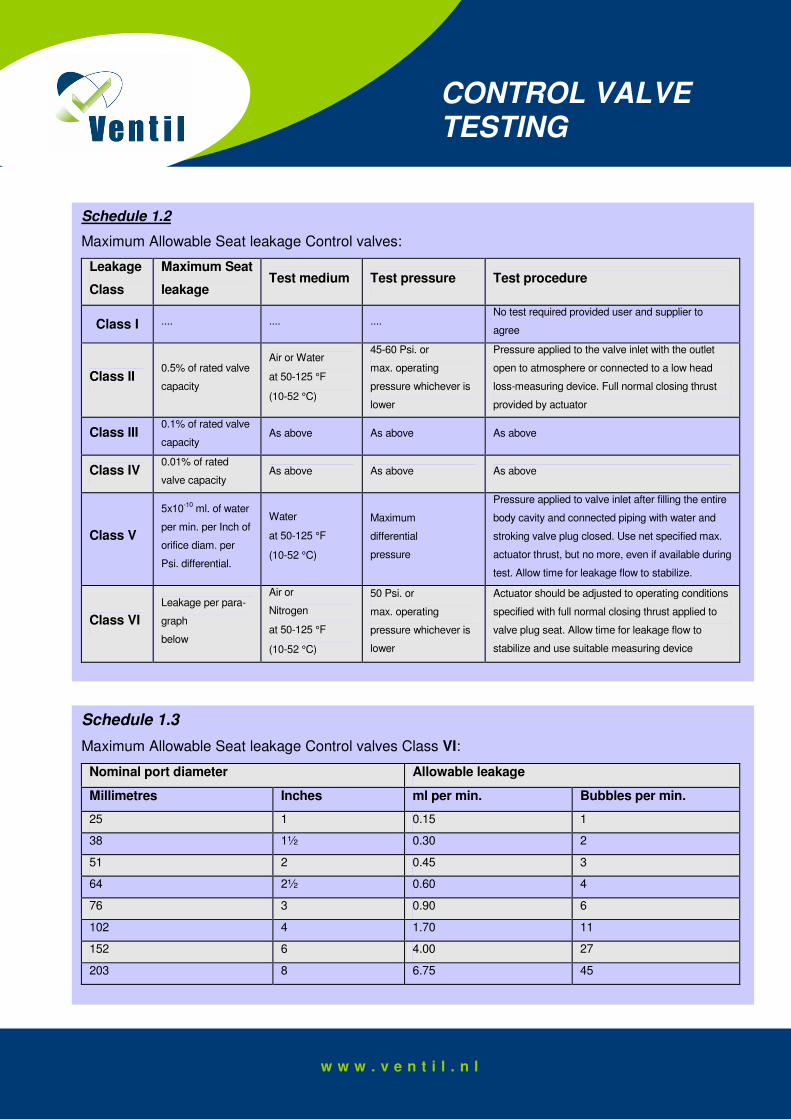
Schedule 1.2
Maximum Allowable Seat leakage Control valves:
Leakage
Class
Maximum Seat
leakage Test medium Test pressure Test procedure
Class I .... .... .... No test required provided user and supplier to
agree
Class II 0.5% of rated valve
capacity
Air or Water
at 50-125 °F
(10-52 °C)
45-60 Psi. or
max. operating
pressure whichever is
lower
Pressure applied to the valve inlet with the outlet
open to atmosphere or connected to a low head
loss-measuring device. Full normal closing thrust
provided by actuator
Class III 0.1% of rated valve
capacity As above As above As above
Class IV 0.01% of rated
valve capacity As above As above As above
Class V
5x10⁻¹⁰
ml. of water
per min. per Inch of
orifice diam. per
Psi. differential.
Water
at 50-125 °F
(10-52 °C)
Maximum
differential
pressure
Pressure applied to valve inlet after filling the entire
body cavity and connected piping with water and
stroking valve plug closed. Use net specified max.
actuator thrust, but no more, even if available during
test. Allow time for leakage flow to stabilize.
Class VI
Leakage per para-
graph
below
Air or
Nitrogen
at 50-125 °F
(10-52 °C)
50 Psi. or
max. operating
pressure whichever is
lower
Actuator should be adjusted to operating conditions
specified with full normal closing thrust applied to
valve plug seat. Allow time for leakage flow to
stabilize and use suitable measuring device
Schedule 1.3
Maximum Allowable Seat leakage Control valves Class VI:
Nominal port diameter Allowable leakage
Millimetres Inches ml per min. Bubbles per min.
25 1 0.15 1
38 1½ 0.30 2
51 2 0.45 3
64 2½ 0.60 4
76 3 0.90 6
102 4 1.70 11
152 6 4.00 27
203 8 6.75 45

w w w . v e n t i l . n l
CONTROL VALVE TESTING
DEFINITIONS
Control valve:
A valve with a power positioning for moving to closure member to any position relative to valve port or ports in
response to and in proportion to an external signal. The energy for a control valve actuator is derived from a
independent source.
Actuator:
A powered valve operator use to open or close a valve; energized by pneumatic, electric, or hydraulic power
sources.
Bubble tight:
A typical requirement for manufacturer's production test meaning no visible seat leakage when tested on gas
(bubbles of air).
Rated travel:
The valve travel at which the manufacturer's rating is established.
Rated valve capacity:
The quantity of test fluid (air or water) that would pass through the valve at rated travel under the stated pressure
conditions as determined by the appropriate equations and manufacturer's ratings.
Seat leakage:
The quantity of test fluid passing through an assembled valve in the closed position under the test conditions as
defined.
Trim:
Internal components associated with isolating or regulating the flow. Includes seating surfaces, closure members
(gate, disk, ball, plug, etc.) stem, bearings, guides, and associated parts.
Text, design and layout by Arthur Baars. We hereby state that this text has been complied meticulously and to the best of our knowledge however, we can in no way guarantee the accuracy or completeness of the information. We therefore do not accept any liability for any damages resulting from actions or decisions based on the information in this text. Users of this text are strongly advised not to use the text solely, but to rely on their professional knowledge and experience, and check the information to be used. Ventil Test Equipment, tel.: +31 70 3209327 – email: [email protected]