conversion of coal to liquids by fischer … archive/files/22_7_chicago... · conversion of coal to...
TRANSCRIPT

CONVERSION OF COAL TO LIQUIDS BY FISCHER-TROPSCH AND OIL/GAS TECHNOLOGIES
J. B. O'Hara, N. E. Mentz, and R. V. Teeple
The Ralph M. Parsons Company Pasadena, C a l i f o r n i a 91124
INTRODUCTION
Conversion of c o a l t o l i q u i d and gaseous f u e l s as w e l l as chemical products has been p r a c t i c e d on a commercial s c a l e i n s e v e r a l areas of t h e world. Pro- j e c t i o n s of U.S. supply and demand ba lances f o r c rude o i l and n a t u r a l gas t o t h e y e a r '2,000 i n d i c a t e t h a t c o a l conversion p l a n t s a r e a candida te i n t h e U.S. f o r product ion of environmental ly acceptab le l i q u i d and gaseous f u e l s . To be compet i t ive w i t h a l t e r n a t i v e energy s o u r c e s , second genera t ion product ion complexes f o r c o a l conversion should b e l a r g e , e f f i c i e n t , s imple and r e l i a b l e .
This paper d e s c r i b e s t h e c h a r a c t e r i s t i c s and p r o j e c t e d economics f o r two candida te second-generat ion technologies , " O i l / G a s " and a U. S. v e r s i o n of Fischer-Tropsch.
The term " O i l / G a s " w a s coined during t h e 1974 P r o j e c t Independence Blue- p r i n t campaign. The process uses a type of c o a l hydro l iquefac t ion s i m i l a r t o SRC 11, wi th r e a c t i o n s e v e r i t y designed t o produce a s i g n i f i c a n t amount of l i g h t hydrocarbons. n a t u r a l gas (SNG) as a prime product . Liquid products i n c l u d e LPG, naphtha, and f u e l o i l .
The suggested U. S . v e r s i o n of Fischer-Tropsch incorpora tes flame-sprayed catalyst on extended heat-exchanger s u r f a c e s y i e l d i n g s e v e r a l p o t e n t i a l advantages inc luding i n c r e a s e d thermal e f f i c i e n c y . systems have been under development by what is now t h e P i t t s b u r g h Energy Research Center (PERC) f o r about 15 years .
The information p r e s e n t e d h e r e is based p r i m a r i l y on conceptual des igns and economic e v a l u a t i o n s prepared by The Ralph M. Parsons Company f o r t h e Major F a c i l i t i e s P r o j e c t Management Div is ion of Energy Research and Development Adminis t ra t ion - F o s s i l Energy (ERDA-FE) f o r each process i n c o r p o r a t e s c e r t a i n process and equipment items now under development, p r i m a r i l y w i t h i n ERDA programs. The des igns are intended t o d e f i n e t h e p o t e n t i a l s f o r second genera t ion c o a l conversion complexes incorpora t ing r e s u l t s o f in-progress development work. I n concept , these complexes might b e c o n s t r u c t e d and opera ted i n t h e mid-'80's t o mid-'90's.
This paper w i l l d e s c r i b e t h e process ing , p r o j e c t e d product c h a r a c t e r i s t i c s , and pro jec ted economics f o r the Fischer-Tropsch and Oil/Gas complexes. These f a c t o r s w i l l t h e n be compared, recogniz ing t h a t each produces s i g n i f - i c a n t l y d i f f e r e n t products . extended by h y d r o t r e a t i n g f u e l o i l t o produce lower percent s u l f u r products at increased c o s t , t o f u r t h e r i l l u s t r a t e t h e f l e x i b i l i t y of t h e technology.
These a r e i n t u r n processed t o y i e l d s u b s t i t u t e
Flame-sprayed c a t a l y s t
The conceptual d e s i g n given
I n a d d i t i o n , t h e O i l / G a s design1 w i l l be
20

Each of these conceptual des igns r e p r e s e n t s on ly one of numerous p o s s i b l e conf igura t ions . For a given i n d u s t r i a l a p p l i c a t i o n with a d e f i n e d c o a l source and requi red product mix, t h e des ign would i n a c t u a l p r a c t i c e be tailor-made f o r t h a t p a r t i c u l a r case.
OIL/GAS
Design Criteria
Prel iminary des ign c r i t e r i a have been p ~ b l i s h e d . ~ p l e t e d conceptual des ign are:
Key elements of t h e com-
P l a n t Locat ion Eas te rn region of t h e U.S. I n t e r i o r Coal Province, which i n c l u d e s p o r t i o n s of t h e states of I l l i n o i s , Ind iana , and Kentucky.
Coal Source
Capacity
I l l i n o i s No. 6 seam c o a l produced i n a c a p t i v e s u r f a c e c o a l mine.
Approximately 47,000 tons p e r day (TPD) of run- of-mine (ROM) c o a l which is cleaned, washed and s i z e d t o produce about 36,000 TPD of c o a l feed t o t h e process p l a n t s . A l l d a i l y f i g u r e s a r e i n s t ream days. Products i n c l u d e about 165 m i l l i o n s tandard cubic f e e t p e r day (MM SCFD) of SNG and approximately 75,000 b a r r e l s p e r day (BPD) of l i q u i d s c o n s i s t i n g of LPG, naphtha, and f u e l o i l .
P l a n t A v a i l a b i l i t y The p l a n t is cons idered t o o p e r a t e at capac i ty 330 stream days p e r y e a r , r e s u l t i n g i n a n a v a i l a b i l i t y f a c t o r of 90.4%.
C h a r a c t e r i s t i c s The complex is a g r a s s r o o t s f a c i l i t y which cap- t i v e l y produces a l l u t i l i t i e s and oxygen requi re - ments. All e f f l u e n t streams are t r e a t e d t o meet environmental s tandards .
Raw Material and F a c i l i t i e s are prouided f o r a 14-day c o a l inventory Product Storage and a 30-day l i q u i d product inventory.
F a c i l i t y Descr ip t ion
An ar t i s t ' s conceptual drawing i s presented i.n F igure 1. model of t h e complex is shown i n F igure 2. imately 600 a c r e s , e x c l u s i v e of t h e c o a l mine. 2,350 people. t h e source r i v e r .
A photograph of a The complex would occupy approx-
P l a n t popula t ion is about drawn from
.
About 17,500 g a l l o n s of water per minute would be
Coal Mine The mine i s an i n t e g r a t e d s t r i p mine w i t h f i v e s e p a r a t e a r e a s o r mining u n i t s t o produce 47,000 TPD of ROM c o a l o p e r a t i n g 350 days p e r y e a r . The average overburden is 60 f e e t and average c o a l seam th ickness i s 5 f e e t . overburden removal is wi th 170 cubic yard drag- l i n e s . The ROM c o a l would pass through a p r i - mary s e p a r a t i o n s t e p l o c a t e d i n t h e mining a r e a
The primary
2 1

and then b e t r a n s f e r r e d by conveyor t o a c o a l p r e p a r a t i o n p l a n t a r e a where it is cleaned and s i z e d t o produce feed c o a l t o t h e process p l a n t .
Over t h e 20-year p r o j e c t o p e r a t i n g l i f e , approxi- mately 57 square mi les would be mined out .
Process P l a n t
A process b l o c k f low diagram is shown i n F igure 3 .
Key t o t h e process i s t h e SRC I1 h y d r o l i q u e f a c t i o n s t e p . of c leaned, s i z e d f e e d c o a l i s s l u r r i e d i n coal-der ived r e c y c l e s o l v e n t ; two-thirds of t h e s o l v e n t is u n f i l t e r e d and c o n t a i n s undissolved c o a l and a s h , while t h e remaining one- th i rd has been f i l t e r e d t o remove t h e s o l i d s . The coa l s l u r r y i s pumped t o 2,050 p s i g , mixed w i t h hydrogen, preheated t o 700°F, and r e a c t e d i n t h e d i s s o l v e r v e s s e l . through a p r e s s u r e let-down system wi th t h e r e s u l t i n g l i q u i d phase going to a l o w p r e s s u r e f r a c t i o n a t o r . F r a c t i o n a t i o n products a r e naphtha, l i g h t d i s t i l l a t e used as f u e l o i l c o n s t i t u t e n t , heavy d i s t i l l a t e used as f i l e r wash o i l and as a product f u e l o i l c o n s t i t u t e n t , and t h e bottoms which c o n t a i n s o l i d s . The bottoms a r e s p l i t ; about h a l f a r e recyc led t o t h e f e e d , c o a l s l u r r y system and t h e remainder goes t o the f i l t e r s .
Here, 20,000 TPD
The d i s s o l v e r product passes
The naphtha is h y d r o t r e a t e d t o produce s a l e a b l e product . t i l l a t e , a p o r t i o n of t h e heavy d i s t i l l a t e , and t h e f i l t r a t e a r e combined t o form t h e product f u e l o i l .
The l i g h t d i s -
Gases e m i t t i n g from t h e d i s s o l v e r p r e s s u r e let-down system, f r a c t i o n a t i o n , and t h e naphtha hydrogenat ion s t e p s a r e combined and fed t o a monoethano- lamine (MEA) ac id g a s removal system t o t a k e o u t t h e hydrogen s u l f i d e , carbon d ioxide and carbonyl s u l f i d e . then processed i n a cryogenic u n i t f o r hydrocarbon recovery /separa t ion as descr ibed below. Sour a c i d gas is s e n t t o a s u l f u r p l a n t which removes t h e s u l f u r - c o n t a i n i n g contaminants and produces s a l e a b l e s u l f u r .
The r e s u l t i n g sweet product gas is
In t h e SNG and LPG product ion t r a i n , sweet gas produced i n t h e M E A system i s d r i e d w i t h molecular s i e v e s and then s e n t t o a cryogenic u n i t . 98.5 volume percent hydrogen is recovered. A p o r t i o n of t h i s hydrogen s t ream is used t o methanate r e s i d u a l carbon monoxide. hydrogen is fed t u t h e naphtha h y d r o t r e a t e r while t h e remainder of t h e
. hydrogen s t ream i s r e c y c l e d t o t h e c o a l d i s s o l v i n g s t e p . Methane-rich g a s produced i n t h e c ryogenic u n i t is compressed, cooled t o remove condens ib le f r a c t i o n s , and then passed through a z i n c oxide guard chamber t o reduce t h e hydrogen s u l f i d e c o n t e n t . It is then processed i n a f i n a l methanat ion u n i t and s e n t t o t h e SNG product l i n e . Ethane and h e a v i e r f r a c t i o n s produced i n t h e cryogenic u n i t a r e f r a c t i o n a t e d t o remove e thane and some propane overhead which is mixed w i t h f i n a l methanator product t o produce s p e c i f i c a t i o n grade SNG, which is compressed t o 1,000 p s i g f o r d e l i v e r y . Remaining propane and h e a v i e r m a t e r i a l i s s e p a r a t e d i n t o propane LPG as an overhead product and a bottoms product . bu tane LPG a s an overhead p r o d u c t , l e a v i n g pentane-and-heavier bottoms which a r e f e d t o the naphtha hydrogenat ion u n i t .
Here
Then t h e h i g h p u r i t y
Bottoms a r e debutanized t o produce
Butane LPG is h y d r o t r e a t e d
22

and t r a n s f e r r e d t o product s t o r a g e .
The make-up hydrogen stream f o r t h e c o a l d i s s o l v i n g s t e p is produced i n a coal- fed g a s i f i e r t h i s pressure . S o l i d s a r e removed from t h e g a s i f i e r e f f l u e n t gas s t ream and t h e hydrogen-to-carbon monoxide r a t i o a d j u s t e d i n a sour s h i f t conversion u n i t . The s h i f t e d g a s i s Processed i n a p h y s i c a l s o l v e n t a c i d gas removal system t o produce a s w e e t gas f o r feed t o t h e d i s s o l v e r s e c t i o n , a hydrogen s u l f i d e - r i c h g a s s t ream f o r feed t o t h e s u l f u r p l a n t , and a carbon dioxide-r ich vent gas stream. The Rect i so l process w a s used a s a r e p r e s e n t a t i v e process .
A f u e l gas g a s i f i e r system is inc luded t o g e n e r a t e t h e necessary s t e a m and Power t o opera te t h e complex. This g a s i f i e r i s f e d by t h e d r i e d d i s s o l v e r f i l t e r cake p l u s c o a l . The f i l t e r cake is previous ly d r i e d t o recover t h e wash so lvent as a s a l e a b l e product . Fuel gas generated in t h e g a s i f i e r i s t r e a t e d i n an a c i d gas removal system t o remove hydrogen s u l f i d e and carbon dioxide before pass ing t o t h e power and steam genera t ion s e c t i o n .
Power and Steam Generat ion
The in-plant produced f u e l gas i s used t o produce electrical power i n two condensing t u r b i n e genera tor u n i t s with t h r e e e x t r a c t i o n p o i n t s . b o i l e r s a r e a l s o included. process p l a n t opera t ion .
Material Balance
The o v e r a l l material ba lance f o r the process p l a n t i s shown i n F i g u r e 4. M a t e r i a l i n p u t s c o n s i s t of c o a l , w a t e r , and oxygen (from the a i r s e p a r a t i o n p l a n t ) . The c o a l amounts t o about 36,000 TPD. S a l e a b l e products , i n c l u d i n g f u e l s , s u l f u r and ammonia, add t o approximately 19,000 TPD.
Energy Balance
The energy ba lance i s depic ted i n F igure 5. The p r o j e c t e d thermal e f f i c i e n c y , c o a l t o s a l e a b l e products , i s about 77%.
FISCHER TROPSCB
Design Criteria
Prel iminary design cr i ter ia have been d e ~ c r i b e d . ~ completed conceptual des ign are:
opera ted a t about 1,000 p s i g . S i g n i f i c a n t methane i s produced a t The g a s i f i e r i s a two-stage e n t r a i n e d s lagging type.
Four steam The u t i l i t y system i s c l o s e l y i n t e g r a t e d w i t h t h e
Key elements of t h e
P l a n t Locat ion E a s t e r n Region of t h e U.S. I n t e r i o r Coal Province.
Coal Source I l l i n o i s No. 6 seam c o a l produced i n a c a p t i v e s u r f a c e c o a l mine.
Capacity Approximately 40,000 TPD of ROM coa l w i l l be mined and 30,000 TPD of c leaned , s i z e d coa l w i l l be f e d t o t h e process p l a n t . The products w i l l have an energy va lue of approximately 525 b i l l i o n Btu p e r day c o n s i s t i n g of 260 MMSCFD of SNG and approxi- mately 50,000 BPD of l i q u i d products which are LPG's, l i g h t and heavy naphthas , d i s s e l f u e l , f u e l o i l and oxygenates.
23

P l a n t A v a i l a b i l i t y 350 stream days per y e a r ; a v a i l a b i l i t y f a c t o r = 90.4%.
C h a r a c t e r i s t i c s G r a s s r o o t s f a c i l i t y producing a l l u t i l i t i e s p l u s oxygen and t r e a t i n g a l l e f f l u e n t streams t o meet environmental s t a n d a r d s .
Raw M a t e r i a l and Fourteen-day coal s t o r a g e and 30day l i q u i d Products S torage product s t o r a g e .
FAci l i ty Descr ip t ion
The complex is depic ted i n t h e art ist 's conceptua l drawing shown i n F igure 6 and a photograph of model of t h e complex is. presented i n F igure 7. Land area required f o r t h e complex, wi thout the c o a l mine, is about 500 acres. P l a n t populat ion i s about 2,100 people. Approximately 12,000 g a l l o n s p e r minute (GPM) of water would be r e q u i r e d .
Coal Mine
A s i n the Oil/Gas des ign , a s t r i p mine wi th an average overburden of 60 f e e t and average seam t h i c k n e s s of 5 f e e t would produce t h e requi red 40,000 TPD of ROM coal . The mine would c o n s i s t of f o u r i n t e g r a t e d mining f a c e s . The primary s e p a r a t i o n and c o a l p r e p a r a t i o n u n i t s a r e similar t o those prev ious ly descr ibed f o r t h e Oil /Gas complex wi th t h e except ion t h a t t h e ground c o a l has a smaller p a r t i c l e s i t e ; minus 20 mesh by 0 f o r Fischer-Tropsch vis-a-vis 5% p l u s 20 mesh, 25% minus 200 mesh f o r t h e Oil/Gas p l a n t .
Process P l a n t
A l l of t h e feed c o a l i s f e d t o two e n t r a i n e d s lagging-type steam oxygen gas i - f iers operated a t approximately 470 p s i g . G a s i f i e r e f f l u e n t gas s t r e a m is exhaus t ive ly cleaned t o remove s o l i d p a r t i c l e s . The r a t i o of hydrogen t o carbon monoxide i n t h e c leaned g a s i s increased by s u b j e c t i n g about 50% of t h e gas stream t o a s h i f t conversion r e a c t i o n ; t h e HP/CO r a t i o i s thereby ad jus ted t o t h e t a r g e t v a l u e of 1.45. S h i f t e d gas is then fed t o an a c i d gas removal u n i t where it is contac ted w i t h a p h y s i c a l so lvent t o remove t h e hydrogen s u l f i d e , carbon d i o x i d e and organic s u l f u r compounds. The Se lexol process w a s used a s a r e p r e s e n t a t i v e process f o r t h i s des ign . The absorbed a c i d g a s e s are s t r i p p e d f o r f u r t h e r process ing; t h e hydrogen s u l f i d e is converted t o s a l e a b l e s u l f u r i n t h e s u l f u r p l a n t and t h e COn stream i s vented. p e r m i l l i o n , volume (ppmv).
Cleaned syngas is f e d t o t h e Fischer-Tropsch s y n t h e s i s u n i t a t about 400 p s i g and 570'F. t r a c e q u a n t i t i e s of s u l f u r compounds. s y n t h e s i s r e a c t o r s designed f o r i so thermal opera t ion . The r e a c t o r s have flame-sprayed i r o n c a t a l y s t depos i ted on t h e e x t e r n a l s u r f a c e of extended s u r f a c e h e a t exchangers. P s i g steam is genera ted on t h e tube s i d e by t h e h e a t of r e a c t i o n . methanation r e a c t o r s have a s i m i l a r geometr ica l design b u t d i f f e r i n the composition of t h e flame-sprayed c a t a l y s t .
S u l f u r c o n t e n t o f t h e cleaned syngas i s reduced t o about 0 .1 p a r t
It f i r s t p a s s e s through zinc oxide guard chambers t o remove Then i t is processed i n 18 p a r a l l e l
React ion t a k e s p lace on t h e s h e l l s i d e and 1,250 S h i f t and
24

Fischer-Tropsch r e a c t o r feeds conta in a r a t i o of r e c y c l e t o f r e s h feed of approximately 1.4. p l a n t thermal e f f i c i e n c y .
Fischer-Tropsch products go t o a l i q u i d product recovery u n i t t o recover l i g h t hydrocarbons from t h e Fischer-Tropsch gas and t o f r a c t i o n a t e t h e l i q u i d s i n t o t h e product streams.
Two gas streams are recovered and f e d t o t h e methanat ion u n i t which produces SNG. One c o n s i s t s of a mixture of r e s i d u a l l e a n gas a f t e r a b s o r p t i o n of t h e C3'S i n a p r e s a t u r a t e d l e a n o i l stream and a CO-rich s t r i p p e r overhead pro- duct produced by s t r i p p i n g a l e a n o i l f r a c t i o n a t o r overhead s t ream. This mixed Stream i s fed t o t h e f i r s t methanat ion s t a g e . I t c o n t a i n s gases pro- duced i n t h e Fischer-Tropsch r e a c t o r , i n c l u d i n g methane and some C 2 ' s and C s ' s t o i n c r e a s e t h e h e a t i n g v a l u e of t h e SNG. An a d d i t i o n a l f e e d stream, which goes t o t h e second-stage methanator , c o n s i s t s of C 3 ' s and C4's which are produced i n a depropanizer i n t h e l i q u i d product r e f i n i n g t r a i n ; they s e r v e t o i n c r e a s e t h e h e a t i n g va lue of t h e SNG.
Fischer-Tropsch l i q u i d s are preheated and fed t o a l e a n o i l f r a c t i o n a t o r where l i g h t ends are removed overhead f o r f u r t h e r process ing and feed t o t h e methanator s e c t i o n as descr ibed previous ly . The bottoms are f e d t o t h e f u e l s vacuum f r a c t i o n a t o r where t h e heavy naphtha, d i e s e l o i l and heavy f u e l o i l a r e produced. Naphtha is removed as an overhead product . Diesel o i l i s withdrawn as a s i d e stream and is steam-str ipped t o o b t a i n t h e f l a s h p o i n t s p e c i f i c a t i o n . s e c t i o n of t h e f r a c t i o n a t o r , cooled , and s e n t t o s t o r a g e .
Light naptha is produced i n a naphtha s t a b i l i z e r fed by t h e bottoms from t h e depropanizer . C 4 LPG's are recovered a s overhead from t h e s t a b i l i z e r .
Oxygenate produced i n t h e Fischer-Tropsch r e a c t o r , conta in ing a h igh a l c o h o l conten t , a r e recovered and r e f i n e d . Feed t o t h e oxygenate recovery system is produced i n a w a t e r e x t r a c t i o n of t h e Fischer-Tropsch l i q u i d s . This feed is preheated and t h e oxygenates taken overhead from a f r a c t i o n a t o r wi th t h e bottoms re turned t o t h e e x t r a c t i o n system. A h o t a l c o h o l - s a l t s o l u t i o n , produced by c a u s t i c n e u t r a l i z a t i o n of t h e Fischer-Tropsch r e a c t o r e f f l u e n t t o des t roy a c i d s produced i n t h e r e a c t i o n , i s s t r i p p e d and t h e oxygenates recovered as an overhead product are a l s o fed t o t h e oxygenate f r a c t i o n a t o r previously d iscussed . The s t r i p p e r bottoms a r e evaported t o produce a con- cent ra ted s a l t s o l u t i o n f o r d i s p o s a l and a consensa te s t ream used as b o i l e r feed water.
Product SNG is produced i n t h e methanat ion s e c t i o n . s u l f u r - f r e e s t r i p p e d gas produced i n t h e l i q u i d product recovery s e c t i o n . The methanation s e c t i o n c o n s i s t s of a f i r s t - s t a g e r e c y c l e r e a c t i o n u n i t conta in ing t h r e e methanators i n p a r a l l e l , and a second-stage one-pass f i n i s h i n g r e a c t o r .
Feed gas t o t h e f i r s t s t a g e methantor is mixed wi th 1.25 p a r t s of r e c y c l e gas , preheated t o about 570°F, and r e a c t e d a t 380 p s i g i n i so thermal r e a c t o r s of design s imi la r t o those used f o r the Fischer-Tropsch r e a c t i o n . A flame- sprayed n i c k e l c a t a l y s t i s depos i ted on t h e o u t s i d e s u r f a c e of a f inned tube hea t exchanger and t h e high h e a t of r e a c t i o n removed by b o i l i n g dowthern i n
Extensive h e a t exchange i s used t o m a i n t a i n a high
Heavy f u e l o i l is produced by steam s t r i p p i n g i n t h e bottom
The pr imary feed is
25

t h e tubes -- t h e h o t dowthern i n t u r n is used t o g e n e r a t e 1,300 p s i g steam f o r use i n t h e p l a n t u t i l i t y system. Reac t ion condi t ions i n t h e f i r s t - s t a g e methanator f a v o r CO methanat ion t o a s s u r e t h a t t h e product SNG does n o t con- t a i n more than 0.1 mol% CO. Product from t h i s f i r s t - s t a g e methanator is cooled, condensate removed, and about th ree- four ths of t h e gas recyc led wi th t h e remainder going t o t h e second-stage methanator which is a n a d i a b a t i c fixed-bed rad ia l - f low r e a c t o r us ing a p e l l a t e d , reduced, n ick le- type c a t a l y s t . Here t h e COn is methanated; it w i l l - a l s o methante CO i f a breakthrough should occur i n t h e f i r s t s t a g e . The COz content of t h e product SNG is maintained below 2 .5%.
The product from t h e second-stage methanator has a h i g h e r h e a t i n g v a l u e of about 910 Btu/SCF. This i s combined w i t h t h e vapor ized mixed l i g h t hydro- carbon stream produced i n t h e l i q u i d product recovery s e c t i o n and f e d t o a h y d r o t r e a t e r f o r s a t u r a t i o n of a lkenes by t h e r e s i d u a l hydrogen i n t h e stream. The product SNG stream is cooled , condensate removed, compressed, d r i e d , and fed t o t h e product p i p e l i n e a t 1,000 p s i g .
POWER AND STEAM GENERATION
The process produces a l l s team r e q u i r e d f o r o p e r a t i o n s , h e a t i n g , and power genera t ion . Therefore , convent iona l steam b o i l e r s are n o t provided f o r normal opera t ion . A s t a r t - u p b o i l e r is provided.
E l e c t r i c a l power is genera ted by four 120-megawatt e x t r a c t i o n s team t u r b i n e genera tors . t h e complex p l u s approximately 140 MW f o r sale.
MATERIAL BALANCE
Overa l l material ba lance f o r t h e process u n i t s is presented i n F igure 8. Resul t s i n d i c a t e t h a t approximately 13,000 t o n s p e r day of s a l e a b l e f u e l products p l u s s u l f u r a r e produced from 30,000 t o n s p e r day of c leaned , s i z e d feed c o a l .
ENERGY BALANCE
Energy balance i s summarized i n F igure 9. Est imated thermal e f f i c i e n c y i n conver t ing c o a l t o s a l e a b l e products i s approximately 70%.
These g e n e r a t o r s provide a l l power r e q u i r e d f o r o p e r a t i o n of
PRODUCT CHARACTERISTICS
Pro jec ted product c h a r a c t e r i s t i c s f o r t h e Fischer-Tropsch and O i l / G a s con- c e p t u a l des igns a r e summarized i n Table 1. These have been p r o j e c t e d based on review and a n a l y s i s of product c h a r a c t e r i s t i c s repor ted by grocess i n - v e s t i g a t o r s f o r similar, b u t no t i d e n t i c a l , p rocess condi t ions y 6 p l u s minor adjustments to r e p o r t e d product c h a r a c t e r i s t i c s us ing t h e c h a r a c t e r i s t i z a t i o n f a c t o r t o a s s u r e cons is tency w i t h t h e b a s i c d a t a . For more r a d i c a l ad jus t - ments to repor ted product c h a r a c t e r i s t i c s as a r e s u l t of subsequent t rea tment , f o r example, hydrogenat ion , r e f e r e n c e w a s made t o publ i shed worksag i n t h i s a r e a t o e s t a b l i s h change of c h a r a c t e r i s t i c s r e s u l t i n g from t rea tment . There a r e not y e t r e p o r t s of product ion-ana lys is - func t iona l product t e s t i n g of l a r g e q u a n t i t i e s of t h e naphtha , d i e s e l f u e l , and f u e l o i l streams. However, t h e p r o j e c t i o n of t h e s e c h a r a c t e r i s t i c s based on a n a l y s i s of e x i s t i n g d a t a and comparison of expected v a l u e s based on analogy t o o t h e r coal-der ived l i q u i d s
26
and s i m i l a r crude oi l -based products provides a b a s i s f o r p r o j e c t i n g compara- t i v e r e s u l t s f o r t h e s e two technologies and d e f i n i n g i n c e n t i v e s f o r p i l o t P l a n t product ion t o permit confirmation o r modi f ica t ion of t h e p r o j e c t i o n s .
The most s i g n i f i c a n t d i f f e r e n c e s a r e t h a t t h e Fischer-Tropsch l i q u i d pro- d u c t s c o n t a i n n i l s u l f u r , n i t r o g e n and p a r t i c u l a t e matter, and are composed pr imar i ly of a l i p h a t i c compounds, whi le t h e Oil/Gas products c o n t a i n s u l f u r , n i t rogen , and s o l i d s and c o n s i s t p r i m a r i l y of aromatics . The Fischer- Tropsch l i q u i d s t h e r e f o r e have h i g h e r p o t e n t i a l f o r use as petrochemical feedstocks and f o r f u e l a p p l i c a t i o n s wi th s t r i n g e n t environmental r e s t r i c t i o n s . Oil/Gas products show promise f o r us i n g a s o l i n e manufacture and f o r s e l e c t e d f u e l a p p l i c a t i o n s . Addi t iona l comments w i l l be presented later r e g a r d i n g poss ib le market v a l u e s of these products .
FIXED CAPITAL INVESTMENTS
All economics a r e expressed i n Fourth Quar te r 1976 d o l l a r s .
The pro jec ted f i x e d c a p i t a l investments (FCI) f o r t h e two conceptua l complexes are compared i n Table 11. The r e s u l t s i n d i c a t e t h a t t h e Fischer-Tropsch complex would r e q u i r e a FCI of approximately 1.55 b i l l i o n d o l l a r s t o produce about 85,000 b a r r e l s of f u e l o i l equiva len t p e r day (BOE/D); t h e FCI p e r BOE/D is t h e r e f o r e about $18,000. The O i l / G a s complex would r e q u i r e a FCI of about $ 1 . 3 b i l l i o n t o produce approximately 110,000 BOE/D f o r a FCI p e r BOE/D of about $12,000.
A comparison of t h e r e l a t i v e c o s t s of t h e s e p a r a t e s e c t i o n s of the complex i s shown i n Table 111. BOE/D f o r the Fischer-Tropsch p l a n t l ies i n t h e g a s i f i c a t i o n s e c t i o n where t h e cos t o f ' t h e oxygen p l a n t s and gas c leanup are much h i g h e r . t h e FCI's f o r t h e conversion s e c t i o n s , p e r d a i l y b a r r e l of o i l e q u i v a l e n t , f o r the two complexes a r e about equal .
A s i g n i f i c a n t c o n t r i b u t o r t o t h e h igher FCI p e r
Hote t h a t
TOTAL CAPITAL INVESTMENTS
Tota l c a p i t a l investments are presented i n Table I V . T o t a l c a p i t a l inc ludes f i x e d c a p i t a l investment , i n i t i a l c a t a l y s t and chemica ls , s t a r t - u p c o s t s , c o n s t r u c t i o n f inanc ing , working c a p i t a l , and l a n d / r i g h t s of way. Pro jec ted t o t a l c a p i t a l requirements are 2.0 and 1 . 7 b i l l i o n d o l l a r s f o r t h e Fischer-Tropsch and O i l / G a s complexes, r e s p e c t i v e l y . Example c o n s t r u c t i o n f inancing c o s t s a r e presented i n each case .
Estimated t i m e t o mechanical complet ion w a s approximately 5 7 months i n each case. This inc luded d e s i g n , engineer ing , procurement and c o n s t r u c t i o n .
OPERATING COSTS
Pro jec ted annual o p e r a t i n g c o s t s f o r t h e complexes are g iven i n Table V . The opera t ing c o s t s i n c l u d e r o y a l t y a l lowance of $1.50 p e r t o n of c leaned , s i z e d coa l produced.
Pro jec ted annual o p e r a t i n g c o s t s are 205 m i l l i o n d o l l a r s f o r bo th t h e Fischer-Tropsch and O i l / G a s complexes, r e s p e c t i v e l y . For a n a l y t i c a l purposes , t h e complexes w e r e d iv ided i n t o c o s t c e n t e r s .
27

REQUIRED PRODUCT SELLING PRICE
Average required product s e l l i n g p r i c e w a s p r o j e c t e d f o r t h r e e p r o j e c t f i n a n c i a l s t r u c t u r e s . I n a l l cases , t h e p r o j e c t o p e r a t i n g l i f e was 20 y e a r s .
o 100% equi ty c a p i t a l o Borrowed c a p i t a l : 65% of t h e t o t a l investment borrowed a t 9%
i n t e r e s t , w i t h t h e p r i n c i p a l repa id i n e q u a l i n s t a l l m e n t s over a 20-year p r o j e c t opera t ing term; a l l working c a p i t a l borrowed at 9% i n t e r e s t f o r t h e 20-year term; a loan commitment f e e of 0.75% on funds n o t drawn down dur ing t h e c o n s t r u c t i o n per iod .
o A nonprof i t (0% discounted cash f low rate of r e t u r n ) o r break- even boundary case .
A 1 2 % discounted cash f low r a t e of r e t u r n (DCF) was s e l e c t e d a s a b a s e case, and t h e revenue r e q u i r e d t o achieve t h i s DCF c a l c u l a t e d f o r each f i n a n c i a l s t r u c t u r e . Required average product s e l l i n g p r i c e w a s then c a l c u l a t e d us ing the requi red revenue and t h e q u a n t i t y of energy products produced.
R e s u l t s a r e summarized i n Table V I . Here we s e e t h a t f o r t h e 65/35 d e b t / equi ty f i n a n c i a l s t r u c t u r e , t h e pro jec ted average requi red product s e l l i n g p r i c e s , f o u r t h q u a r t e r 1976 b a s i s , (RPSP) are $2.55 and $1.95 p e r m i l l i o n Btu 's f o r t h e Fischer-Tropsch and Oil/Gas c a s e s , r e s p e c t i v e l y . The 100% equi ty f inancing c a s e s a r e about 30 percent h igher i n each case. The breakeven c a s e s are about $1.50 and $1.20 per m i l l i o n Btu ' s , r e s p e c t i v e l y .
I n d o l l a r s per b a r r e l , t h e 65/35 debt /equi ty case RPSP's would be about $15.25 and $12.00; t h i s i s based on a n a r b i t r a r y 6 m i l l i o n Btu per b a r r e l re fe rence va lue . . A key f a c t o r i n t h e economic p r o j e c t i o n s is t h e inc lus ion of l a r g e c a p t i v e c o a l mines i n the complexes.
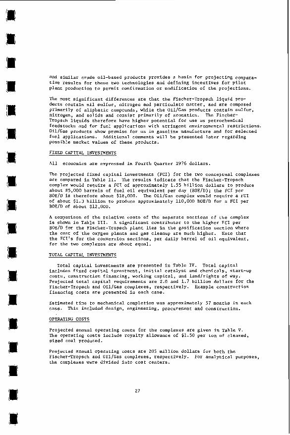
SENSITIVITIES
S e n s i t i v i t i e s of t h e average requi red product s e l l i n g p r i c e t o changes i n '
key economic parameters are shown i n Table V I I . The RPSP i s most s e n s i t i v e t o changes i n f i x e d c a p i t a l investment . To i l l u s t r a t e , f o r Fischer-Tropsch a 10% reduct ion i n f i x e d c a p i t a l investment would r e s u l t i n an 8.7% reduc- t i o n i n RPSP f o r t h e 100% e q u i t y case. The s e n s i t i v i t i e s t o o p e r a t i n g c o s t s a r e i n t h e range of 15-20%.
E f f e c t of v a r i a t i o n s i n DCF on the RPSP is presented i n F igure 10 f o r t h e 65% debt case. S e n s i t i v i t y i s g r e a t e r f o r t h e 100% equi ty c a s e , which is not shown.
POSSIBLE PRODUCT MARKET VALUES
A b r i e f assessment of p o s s i b l e product market va lues and t h e e f f e c t o f t h e r e s u l t i n g p r o j e c t revenues on p r o f i t a b i l i t y w a s completed. p o s s i b l e market v a l u e s , t h e p r o j e c t c h a r a c t e r i s t i c s of t h e products were compared wi th those of convent iona l crude oi l -based products . Discussions were held w i t h r e p r e s e n t a t i v e s of f u e l producers and consumers and indus t ry r e p o r t s were reviewed.
To o b t a i n these
28

Indus t ry r e p r e s e n t a t i v e s s t r o n g l y q u a l i f i e d t h e i r op in ions on p o s s i b l e p r i c e s by S t a t i n g t h a t l a b o r a t o r y and f i e l d product performance t e s t s must be con- ducted before f i rm d o l l a r v a l u e s could b e assigned t o t h e products .
With t h e above cavea ts c l e a r l y i n mind, p o s s i b l e u n i t s a l e s v a l u e s and annual revenues f o r a f o u r t h q u a r t e r 1975 b a s i s a r e presented i n Table V I 1 1 f o r Fischer-Tropsch and Table 1); f o r Oil/Gas; t h e s e are taken from t h e publ ished repor t s . ' " s a l e of SNG produced commercially from naphtha, and p o s s i b l e v a l u e s f o r SNG from c o a l a t t h a t time. These p o s s i b l e s a l e s v a l u e s a r e presented t o i l l u s t r a t e t h e e f f e c t of product s a l e s v a l u e on t h e economics and a l s o t o perhaps s t i m u l a t e f u r t h e r e f f o r t t o e s t a b l i s h f i r m product v a l u e s and marke tab i l i ty .
The Tables V I 1 1 and I X p o s s i b l e annual revenues were then updated t o a f o u r t h q u a r t e r 1976 b a s i s us ing Federa l Energy Adminis t ra t ion d a t a which ind ica ted t h a t f u e l p r i c e s e s c a l a t e d approximately 9 percent from f o u r t h q u a r t e r 1975 t o f o u r t h q u a r t e r 1976.
Resul t s of t h i s second-order explora tory a n a l y s i s i n d i c a t e t h a t p o s s i b l e average annual revenues (Fourth Quarter 1976 d o l l a r s ) are $730 and $560 m i l l i o n d o l l a r s f o r t h e Fischer-Tropsch tnd O i l / G a s c a s e s , r e s p e c t i v e l y . Pro jec ted DCF'S c a l c u l a t e d us ing t h e s e revenues and t h e p r o j e c t s t r u c t u r e s developed e a r l i e r are shown i n Table X. To i l l u s t r a t e , f o r t h e 65/55 debt / equi ty c a s e , t h e p r o j e c t e d DCF's f o r Fischer-Tropsch and Oil/Gas are 27 and 20 p e r c e n t , r e s p e c t i v e l y . This r e s u l t i n d i c a t e s t h e i n c e n t i v e f o r a c c u r a t e assessment of t h e m a r k e t a b i l i t y and p r o f i t a b i l i t y of s y n f u e l products t o be produced i n second genera t ion c o a l conversion p l a n t s i n t h e U.S.
ECONOMIC COMPARISON FOR LOW SULFUR CONTENT FUEL PRODUCTS.
Pro jec ted s u l f u r conten t of t h e Oil/Gas f u e l o i l is 0.45. pre l iminary a n a l y s i s of t h e e f f e c t of f u r t h e r hydro t rea t ing t o reduce t h e s u l f u r conten t on c o s t and product composition was made; t h i s is an ex tens ion of t h e design previous ly reported. ' t h e c o s t s and i m p l i c a t i o n s of producing very low s u l f u r f u e l s from c o a l by O i l / G a s type technology f o r environmental reasons.
The d a t a b a s i s f o r p r e d i c t i n g process and c o s t r e s u l t s f o r h y d r o t r e a t i n g t h e coal-derived l i q u i d s ii Bimited. guide t h e p r o j e c t i o n s . ' 'lo
Prel iminary process designs were developed f o r incremental h y d r o t r e a t i n g of t h e O i l / G a s f u e l o i l . Hydrotreat ing condi t ions were nominally 650°F and 2,500 p s i g wi th a nickel-molybenum type c a t a l y s t . A 6 months c a t a l y s t l i f e was assumed f o r t h e purpose of t h i s pre l iminary assessment .
Pro jec ted product d i s t r i b u t i o n as a f u n c t i o n of f u e l o i l s u l f u r c o n t e n t is depic ted i n F igure 11. With decreas ing s u l f u r conten t , t h e amount of f u e l o i l decreases and t h e l i g h t e r products i n c r e a s e .
F igure 12 p r e s e n t s p r o j e c t i o n s of hydrogen consumptions and Figure 1 3 shows pro jec ted requi red average product s e l l i n g p r i c e a t 12% DCF, 65% d e b t as a func t ion of f u e l o i l s u l f u r conten t . Also shown on Figure 13 i s t h e pro jec ted
The SNG s a l e s v a l u e w a s based on va lue allowed f o r
A b r i e f and very
The r e s u l t provides guidance regard ing
However, some information is a v a i l a b l e t o
29

RPSP f o r n i l s u l f u r Fischer-Tropsch products . R e s u l t s i n d i c a t e t h a t a t about 98% s u l f u r r e d u c t i o n i n O i l / G a s f u e l o i l , t h e requi red product s e l l i n g p r i c e s a r e approximately equal .
SUMMARY AND CONCLUSIONS
Conceptual designs 'economic e v a l u a t i o n s f o r two condida te second genera t ion c o a l conversion technologies have been completed by t h e Ralph M. Parsons Company. These a r e a sugges ted f u t u r e v e r s i o n of a Fischer-Tropsch complex, and an O i l / G a s Complex which u s e s SRC I1 technology. Each conceptual d e s i g n incorporated c e r t a i n process and equipment concepts c u r r e n t l y under develop- ment. The des igns are based on t h e presumption t h a t these development programs w i l l be s u c c e s s f u l .
The conceptual complexes process 30,000-36,000 tons p e r day and produce 85,000-110,000 b a r r e l s p e r stream day of o i l e q u i v a l e n t . c a p i t a l investments f o r t h e Fischer-Tropsch (F-T) and O i l / G a s (O/G) complexes a r e 1.55 and 1.3 b i l l i o n d o l l a r s , r e s p e c t i v e l y ; a l l economics a r e presented i n f o u r t h q u a r t e r 1976 d o l l a r s . Uni t f i x e d c a p i t a l investments , expressed a s d o l l a r s p e r d a i l y b a r r e l o i l equiva len t (BOEID) are about $18,000 and $12,000, r e s p e c t i v e l y .
P r o j e c t e d f i x e d
Pro jec ted product c h a r a c t e r i s t i c s from t h e complexes d i f f e r ; Fischer-Tropsch produces p r i m a r i l y a l i p h a t i c l i q u i d s and Oil /Gas p r i m a r i l y aromatics .
Pro jec ted r e q u i r e d s e l l i n g p r i c e s t o achieve a 12% DCF us ing a 65% d e b t , 9% i n t e r e s t c a s e a r e about $15.25 and $12.00 p e r equiva len t b a r r e l . A second order assessment of p o s s i b l e product s a l e s va lues has l e d t o t h e conclus ion t h a t DCF'S of the o r d e r o f 20% might be achieved; t h i s is presented t o i l l u s t r a t e the i n c e n t i v e t o produce and test enough of t h e s y n f u e l s t o determine t h e i r market v a l u e s .
P r o j e c t i o n s o f p o s s i b l e c o s t s f o r h y d r o t r e a t i n g a 0.4% s u l f u r O i l / G a s f u e l o i l t o reduce its s u l f u r c o n t e n t have been presented . R e s u l t s i n d i c a t e t h a t reducing t h e s u l f u r c o n t e n t t o 0.1% would add an incrementa l $500 m i l l i o n t o t h e f ixed c a p i t a l investment and reduce t h e q u a n t i t y of f u e l o i l by about 6 percent w h i l e i n c r e a s i n g t h e q u a n t i t i e s of LPG's and naphtha. r e s u l t i s a 1 5 percent i n c r e a s e i n t h e average requi red product s e l l i n g p r i c e (RPSP). of t h e n i l s u l f u r F-T RPSP. A t 98% s u l f u r reduct ion i n O i l / G a s f u e l o i l , t h e RPSP's a r e about equal . t r e a t i n g s t e p . A n i n c e n t i v e e x i s t s t o develop a f i r m b a s i s f o r d e s i g n and p r e d i c t i o n of economics.
A f u r t h e r
The average RPSP a t t h i s s u l f u r level is p r o j e c t e d t o be about 90%
Limited informat ion i s a v a i l a b l e f o r t h i s hydro-
Fischer-Tropsch and O i l / G a s coal conversion technologies each o f f e r d i f f e r e n t advantages and p o t e n t i a l problems t o be overcome. candida tes f o r any f u t u r e synfuels-from-coal programs.
They must be cons idered
ACKNOWLEDGEMENT There a r e many c o n t r i b u t o r s t o designs/assessments of t h i s scope. The guidance of Messrs. D. G a r r e t t and N. P. Cochran of t h e Major F a c i l i t i e s P r o j e c t Manage- ment Div is ion of ERDA - F o s s i l Energy is g r a t e f u l l y acknowledged. Also, t h e c o n t r i b u t i o n s of Messrs. A. Bela , S. M. Fass , G. H. Hervey, R. D. Howell, H.W. Klumpe, B. I. Loran, E. A. M i l l s and D. G. Reynolds, a l l of Parsons.
30

1.
2 .
3.
4 .
5 .
6.
7 .
8 .
9 .
10 .
LITERATURE CITED
O'Hara, J . B . , Hervey, G . H . , Fass , S . M . , J e n t z , N . E . , Klumpe, H. W . , Loran, B . I . , Mills, E . A . , Teep le , R . V . , "Oil/Gas Complex Concep- t u a l Design/Economic Ana lys i s , O i l and SNG Produc t ion , " RED Report No. 114 - In t e r im Report No. 4 , Prepared f o r t h e Energy Research and Development Admin i s t r a t ion , March, 1977.
O'Hara, J . B . , Bela, A . , J e n t z , N . E . , Khaderi , S . K . , Klumpe, H . W . , Loran, B . I . , Reynolds, D . G . , Teep le , R . V . , "Fischer-Tropsch Complex Conceptual Design/Econornic Ana lys i s , O i l and SNG Produc t ion , " RED Report No. 114 - In t e r im Report No. 3 , Prepared f o r t h e Energy Research and Development Admin i s t r a t ion , J anua ry , 1977.
O'Hara, J . B . , Hervey, G . H . , Fass, S . M . , and Mills, E . A . , "Oil/Gas P l a n t Design C r i t e r i a , " P resen ted a t t h e 68 th Annual Meeting o f t h e American I n s t i t u t e of Chemical Engineers (AIChE), Los Angeles, C a l i f . , November 19, 1975.
O'Hara, J . B . , Bela, A . , J e n t z , N . E . , and Khaderi, S . K . , "Fischer-Tropsch P l a n t Design C r i t e r i a , " P resen ted a t t h e 68th Annual Meeting o f t h e American I n s t i t u t e of Chemical Engineers (AIChE), Los Angeles, C a l i f . , November 19, 1975.
P i t t s b u r g h & Midway Coal Mining Company, ERDA Monthly P rogres s Report f o r August, 1975, ERDA Con t rac t No. E(49-18)-469, September, 1975.
E l l i o t , J . J., Haynes, W . A . , and Forney, A . J . , "Gasol ine Via t h e Fischer-Tropsch React ion Using t h e Hot Gas Recycle System," 163rd Nat ional Meeting of t h e American Chemical S o c i e t y , Boston, Mass., A p r i l , 1972.
Federal Energy Admin i s t r a t ion , Monthly Energy Review, March, 1977.
FFIC Corporat ion, O f f i c e of Coal Research Monthly P rogres s Reports No. 13 through No. 36, U.S. Government Con t rac t 14-32-0001-1212. September, 1972 through August, 1974.
S c o t t i , L . J . , P!c?lunn, B . D., Greene, M . I . , P l e r r i l l , R . C . , Shoemann, F . H . , Te rz i an , H . D., Ford, L . , Domina, D . J . and Jones , J . F . , "Evaluat ion of COED Syncrude," RED Report No. 73 - In t e r im Report No. 3 , p.repared f o r O f f i c e o f Coal Research, J anua ry 6 , 1975.
Ralph M . Parsons p r o p r i e t a r y d a t a f i l e s .
31

32

33

t 34

COAL (2.7% MOISTURE)
35.670 TPD
FUEL OIL 11,310 TPD
SULFUR 1,250 TPD r
AMMONIA 90 TPD
OXYGEN 4.500 TPD
WATER 57,750 TPD-
3,940 TPD --I-- BUTANE LPG 410 TPD
NAPHTHA 1,280 TPD
01 LIGAS PROCESS
UNITS
I I
SLAG 4,210 TPO - WASTE GAS (COP et al.) 22,950 TPo -
I WATER LOSSES 51,950 TPD /
TOTAL IN =OUT 97.920 TPO
ALL FIGURES IN SHORT TONS
Figure 4 - Overall Material Balance Oil/Gas Plant
35

CLEAN COAL
36,040 b
SULFUR
STEAM AND POWER GENERATION
SULFUR REMOVAL
SNG
7254
PROCESS UNITS
PROPANE LPG
958 ’ BUTANE LPG
OXYGEN PLANT 721 ’
NAPHTHA FUEL GAS PRODUCTION
2.258 ’
~-
ALL FIGURES ARE M M 8TU/HR, HHV
= 77.6% THERMAL = 7.254 + 958 + 721 + 2258 + 16.283 + 406 + 71 36,040
Figure 5 - Thermal Efficiency, Oil/Gas Plant
36


COAL
AIR
WATER
TOTAL
30.000 TPD 4
105,890 TPD I
8,925 TPD I
8 PROCESS
UNITS
-r
'RODUCTS 13.600 TF'D
SNG 6,590 TPD Butanes 340 TPD
2,380 TPD Naphthas Oxygenates 455 TPD Diesel Fuel 2,105 TPD Premium
Fuel Oil 715 TPD Sulfur 1,015 TPD
INTERNAL CONSUMPTION 210 TPD
Acids to lnplant Disposal 45 TPD Miscellaneous 165 TPD
i SLAG 2,350 TPD
144,815 TF'D
Figure 8 . Overall Material Balance Fischer-Tropsch Plant
39
144,815 TPD

PROCESS UNITS
COAL PREPARATION AND COAL MINE
OXVGENPLANT 1, I SULFUR REMOVAL
267.78
LIQUID PRODUCTS
237.56 ’ SULFUR
8.09
ELECTRICAL POWER FOR SALE
11.43 ’ ALL FIGURES ARE MMM ETUIO. HHV
Figure 9 -Thermal Efficiency Fischer-Tropsch Plant
40

0 6 12 18 DCF R ~ T E OF RETURN (%)
Figure 70 ~ Sensitivity of Required Product Selling Price to DCF, 65% Debt Case
41

BUTA - PROPP
SULFUR IN FUEL OIL (%I
Figure 11 . Projected Product Distribution Product Yield vs. Fuel Oil Sulfur Content
OiVGas Plant
42

n YL y1 Y
a a
a n 4
u)
s x
SULFUR IN F U E L OIL 19/01
Figure 12 - Projected Hydrogen Consumption Hydrogen Consumed vs. Fuel Oil Sulfur Content
Oil/Gas Plant
4 3

0
f c
44

Table I . Comparison of P r o j e c t e d Product C h a r a c t e r i s t i c s
Product
SNG
C3 LPG
C4 LPG
F u l l Range Naphtha
Light Naphtha
Heavy Naphtha
Diesel Fuel
Fuel Oi l
P r o j e c t e d ChTrac
Fischer-Tropsch
P i p e l i n e Q u a l i t y
Mixed Butane - Butylene 37 p s i a Vapor P r e s s u r e
N i l S u l f u r 185'F ASTM EP 8S.S0API Gravi ty
N i l Sulfur 300°F ASTM EP 71.3 S I Gravi ty
57OAPI Gravi ty 60 p l u s Cetane Number N i l S u l f u r , N i l Ni t rogen
41OAPI Gravi ty ' N i l Sulfur Higher Heat ing Value: 19,900 Btu / lb
45
r i s t i c s
Oi 1/ Gas
P i p e l i n e Q u a l i t y
Propane 210 p s i a Vapor P r e s s u r e
Mixed Propane- Butane, 70 p s i a Vapor P r e s s u r e
500 API Gravi ty C 5 t o 380'F ASTM EP High Naphthene
-8.2OAPI G r a v i t y 0 .4 w t % S u l f u r Higher Heat ing Value: 17,200 Btu / lb

Table 11. Comparison of Fixed Capital Investments (FCI) for Fischer-Tropsch and Oil/Gas Complexes
Barrels Fuel Oil Equivalent/Day (BPOE/D): F-T = 86,000 O/G = 110,000
,Uno and Coal Prepara t ion Mine coal Prepara t ion Coal storage Crushing and Dryins
Subcora l
Conversion Fixher -Tropsch S y n t h e s i s O i l Recovery and F r a c t i o n a t i o n Chemical Recover, Slurry and Dissolv ing F i l t r a t i o n UllflllaLlOn Dissolver Acid Gar Removal
Subto ta l
Process Gar Producrion Gzriflcatlo" Hear Rec. and Pai r . Removal A c i d Gir Renova1 ShiiL Poser Generation
SLbfOf31
SSG Separar lon and Treatment \bfh.MflO" Sh'G and LPG Trer:lne
Subroca l
Pmduct F in ish ing Sul fur Plant Srphrha Hydrogenation
S u b t o t a l
U t i l i t i e ~ oxygen P h n r InlTrYmenT 3.m Plant h l r Pomble and Sanitary !fater RJI later System Fuel Gas Gasify Fuel Car Acid Gas R m o v u l Raw Later Trea t ing
S i b l o m i
Envlronren~al and Gecers? F a c i l i t i e s
Gencrrl Frcilitivi la tor Reclaiming Eiflurnt Wafer Treating
Sour hazer S t r i p p i n g ProJ'Lct s t o r a g e
SubtafPI
Total C0NIr"CtC.a cos1
Hone Off ice C o i f s Sales Tax
Total Fixed Cnpi rJ l lnvestmeni (Fc i )
FCI/(BFQE/O)
Fi rcher -Troprch 5 Millions
175.6 22.0 11.2 13.0
221.8
20J. 6 30.5 15.9 ..
.. __ 251.0
3 7 . 3 1 5 1 . 2 100.3
18.9 119 .6
327 .3 -
60.6
- 60.6
22.1 -. - 2 2 . 1
305.3 3 . 5 0.4
:3.5 .. ..
- 355.1
19 5 10.4 3.0
/ I - _. . - -
83. I
1,JiO.O
150.2 28. I
I . s70 .3 -
18, 250
46
211.6 30.0 13.0 15.1
269.7 -
_ _ 216.8 32.0 31.6 20.3
310.7
45.4
57.7 59.5 86.8
239.2
0.6 48.3
58.9 -
1S.J 9.2
24.6 -
90.2 z . 5
71.2 17.9 16.5
138.2 -
37.2
5.S 32.2
5 . 9
80.8
1,172.5
117.2 23.5
1,313.0
-
-
11,950

\
Table 111. Comparison of R e l a t i v e Fixed C a p i t a l Investments of Fischer-Tropsch and O i l / G a s by U n i t u D e s c r i p t i o n
~~
Mining & Coal P r e p a r a t i o n
Conversion
Process Gas Product ion
S N G S e p a r a t i o n & Treatment
Product F i n i s h i n g
U t i l i t i e s
Environmental & General F a c i l i t i e s
T o t a l
R a t i o of F ischer -Tropsch t o Oil/Gas
Fixed C a p i t a l Investment I FC I /BOE
1 .os 1.03
2.28
1.58
1.15
2.16
1 .33
1.53
Table I V . Comparison o f P r o j e c t e d T o t a l C a p i t a l Requirements f o r Fischer-Tropsch and Oil /Gas Complexes
Item
Fixed C a p i t a l Investment
I n i t i a l C a t a l y s t 6 Chemicals
S t a r t - u p Cos ts
C o n s t r u c t i o n Financinga
Working C a p i t a l
Land, Rights of Way
TOTAL
Say
Fischer-Tropsch $ ml
1550
11
110
212
115
1 - 1997
2000 -
O i l / G a s s ml
1300
9
86
188
107
1
1691
1700
-
-
R a t i o F-T - O/G
1 . 1 9 I I 1 . 2 2
1.13 1.28 I " I 1 . 0 0
a ) Example: F o r 65/55 d e b t / e q u i t y , 9% i n t e r e s t , 0 .75% commitment f e e case .
47

Table V. Comparison of P r o j e c t e d Annual Opera t ing Costs f o r Fischer-Tropsch and Oil/Gas Complexes
P r o j e c t F i n a n c i a l S t r u c t u r e
100% Equity
65/35 Debt /Equi ty
Breakeven
Cos t Center
Coal Mine
Coal P r e p a r t i o n
Process P l a n t
Power P l a n t
O f f s i t e s
TOTAL
s a y
R a t i o Fischer-Tropsch Oil/Gas F-T - O / G
3.30 2.50 1 . 3 2
2.55 1.95 1 . 2 8
1.50 1 . 2 0 1 . 2 0
Annual Opera t ing Cos ts - $MM
Fischer-Tropsch
84.5
2 . 3
101 .5
7 . 7
7.8
203.8
205 - -
O i 1/ Gas
104.2
3 .2
84.4
14.4
206.2
205 - -
Table V I . Comparison o f P r o j e c t e d Average Required Product S e l l i n g P r i c e a t 12% DCF
Required Average Product S e l l i n g P r i c e i n D o l l a r s p e r M i l l i o n BTU 1
-.
I
1: li
48
1 I
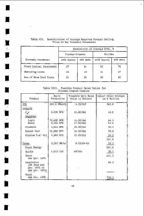
Table VII. S e n s i t i v i t i e s of Average Required Product S e l l i n g P r i c e t o Key Economic Parameters
Economic Parameter
Fixed C a p i t a l Investment
Operat ing Cos ts
Run of Mine Coal Cos ts
S e n s i t i v i t y of Average RPSD, %
Fischer-Tropsch Oil /Gas
100% Equity 65% Debt 100% Equi ty 65% Debt
87 81 82 78
15 19 2 1 27
21 25 30 34
Table V I I I . P o s s i b l e Product S a l e s Values f o r Fischer-Tropsch Complex
Product
SNG
Liquids -
c4s Naphthas
Light Heavy
Alcohols
Diese l Fuel
Premium Fuel O i l
Power - T o t a l Energy
S u l f u r
T o t a l
E s c a l a t i o n
4 th Qtr. 1975
(9% from 4 t h Qtr. 1975 t o 4 th Qtr. 1976)
4-th O t r . 1976 T o t a l
Dai ly Product ion
260.0 MMscfd
3,535 BPD
10,620 BPD 9,555 BPD
3,910 BPD
16,960 BPD
4,960 BPD
3,352 bnV/hr
1 ,015 Ton
P o s s i b l e Unit S a l e s Value i n D o l l a r s
4.25/Elcf
12.00/bbl
15.50/bbl 17 .00/bbl
25.00/bbl
14.50/bbl
15.00/bbl
0.03/klV-hr
60/ ton
innual Gross Revenue i n $ lYill ion
562.8
1 4 . 0
54 .3 53.6
32.3
79.9
24.5
241.6
33 .2
651.6
20.1
671 .7
-
-
-
60.5
732.2 - 49

Table I X . P o s s i b l e Product S a l e s Values f o r Oil/Gas Complex
P r o j e c t F i n a n c i a l S t r u c t u r e
100% Equity
65/35 Debt /Equi ty
Product
DCF
Fischer-Tropsch Oil/Gas
17 15
27 20
~
SNG
Propane
Butane
Naphthas
Fuel O i l
T o t a l Energy
Sul fur
.4mmonia
T o t a l 4 t h Qtr. 1975
E s c a l a t i o n (9% from 4 t h Qtr. 1975 t o 4 t h Qtr. 1976)
T o t a l 4 t h Qtr. 1976
~ ~ ~~
Dai ly Product ion
170 MElscfd
6 ,030 BPD
4,100 BPD
9,400 BPD
56,400 BPD
118 LT/D
90 ST/D
~~ ~~
' o s s i b l e Unit S a l e s Value i n D o l l a r s
4.25/Mcf
11.00/bbl
12.00/bbl
15.50/bbl
9 .75/bbl
60/ t o n
120/ t o n
~~~ ~~~~~
Annual Gross Revenue i n $ M i l l i o n
238.425
21.890
16.235
48.080
181.470
506.100
2.335
5.565
514.000
46.000
560.000
Table X . DCF's f o r P o s s i b l e Product Revenues
I' 1. I
I
I
50 I' II
I
I