corsnet-nsw and airborne lidar: g05-2336 a match...

1
CORSnet-NSW and Airborne LiDAR: A Match Made in Heaven G. Jones 1 , O.L. Colombo 2 , V. Janssen 1 , S. Brunker 1 and C. Rizos 3 1 NSW Land and Property Information, Bathurst, Australia 2 NASA, Greenbelt MD, USA 3 The University of New South Wales, Sydney, Australia [email protected] [email protected] INTRODUCTION CORSnet-NSW is a rapidly growing network of Global Navigation Satellite System (GNSS) Continuously Operating Reference Stations (CORS) providing fundamental positioning G05-2336 28 June – 7 July 2011 TEST RESULTS The trajectory comparison in Figure 5 shows the vertical component of five wide- infrastructure for New South Wales that is accurate, reliable and easy to use [1,2]. Airborne LiDAR (Light Detection and Ranging) surveys produce very accurate, high-resolution terrain models which are used for many surveying and engineering applications including critical environmental analysis functions such as coastal vulnerability, flood inundation mapping, assessment of the impact of rising sea levels and hydrological modelling for water resource management. The key to producing high-quality elevation products is very precise geolocation and orientation of the LiDAR instrument during the survey, obtained with a combination of on- board GNSS and inertial navigation system (INS) sensors (Figure 2). If the LiDAR survey is to achieve the now expected high level of vertical accuracy (±15 cm, 1 sigma), then the position of area derived trajectories, using various combinations of CORSnet-NSW sites, compared to the locally derived trajectory (using AIR2). The results show a remarkably consistent comparison with the locally derived solution. The spikes visible in the DBBO/WGGA/NEWC (yellow) solution are attributed to small data glitches at DBBO. Unfortunately, LiDAR observations were not being collected at those instances, therefore the effect on ground data could not be fully assessed. CORSnet-NSW supports a wide range of GNSS applications in areas such as surveying, agriculture, mining and construction, and provides a solid platform for research and innovation involving satellite positioning technology. The network is built, owned and operated by Land and Property Information (LPI), a division of the NSW Department of Finance and Services. Currently consisting of about 65 permanent stations tracking multiple satellite constellations, CORSnet-NSW will expand to over 120 stations within the next two years (Figure 1). Figure 1: Current Status of CORSnet-NSW (June 2011). Figure 5: Trajectory comparison using CORSnet-NSW sites. Relative point comparisons were performed in 25 sample areas of 100 m 2 in size (consisting of 1700 points in total). Table 1 summarises the displacement vectors between individual LiDAR points derived from five wide-area solutions compared with those from the locally derived solution utilising AIR2. The results clearly show that the height values agree to within a few centimetres, Table 1: Displacement vectors of LiDAR points in metres. CORSnet-NSW sites Min. Max. Average BALL (626 km baseline) East -0.013 -0.005 -0.009 North -0.034 0.012 -0.012 Vertical -0.031 -0.003 -0.020 BALL/GFTN (average 570 km baseline) East -0.009 0.002 -0.004 North -0.036 0.007 -0.015 Vertical -0.048 -0.014 -0.037 DBBO/WGGA/NEWC (average 220 km baseline) East -0.035 -0.026 -0.031 North -0.031 -0.002 -0.016 Vertical -0.020 0.017 -0.008 WGGA (280 km baseline) East -0.024 -0.009 -0.018 North -0.028 0.000 -0.014 Vertical -0.027 0.015 -0.016 02:32 UT 04:06 UT Ideally, permanent GNSS reference stations would be available for precise airborne positioning achieve the now expected high level of vertical accuracy (±15 cm, 1 sigma), then the position of the GNSS/INS-derived aircraft trajectory for each laser swath must be determined with a relative precision in the order of just a few centimetres. The GNSS positions are then blended with high-frequency measurements taken by the onboard INS to produce the final trajectory and reference orientations of the LiDAR instrument. WIDE-AREA DIFFERENTIAL GNSS Figure 2: Airborne LiDAR “reference frame”. The usual practice to achieve this is to deploy temporary GNSS receivers at sites within the survey area, utilising differential GNSS techniques to obtain a precise aircraft trajectory. For reliable ambiguity resolution the aircraft generally needs to be no further than 30 – 50 km from these temporary or permanent reference stations at all times. Therefore, if the area surveyed is large, this requires a significant logistical overhead in operating receivers at multiple sites during a flight mission. even over baselines exceeding 600 km. Vertical -0.027 0.015 -0.016 WGGA/GLBN/NEWC (average 210 km baseline) East -0.006 0.004 -0.002 North -0.029 0.003 -0.015 Vertical -0.020 0.017 -0.009 In order to investigate how the DEM surfaces derived from each trajectory compare across the entire data swath, raster surfaces were created from the LiDAR point data. Each surface was then subtracted from the local solution to create a difference surface. The result shown in Figure 6 was typical of the cyclical effect evident for all solutions with a magnitude in the order of 2-3 cm, which has an expected correlation with the related trajectories as shown in Figure 7. Figure 6: DEM surface difference. Figure 7: Trajectory segments for DEM generation. Finally, the LiDAR surfaces derived from trajectories using all wide-area differential GNSS solutions, the Table 2: Comparison of LiDAR surfaces with surveyed ground control (meters). GPS Time (seconds) Ideally, permanent GNSS reference stations would be available for precise airborne positioning across the full extent of New South Wales. The reality is that although CORSnet-NSW will provide substantial state-wide coverage, existing “off-the-shelf” software currently used to process such dynamic GNSS observations requires a density of CORS sites that is neither practical nor economically viable to establish. The solution is to combine the positioning infrastructure provided by CORSnet-NSW with a wide-area GNSS technique which removes the cost, logistical and computational complications of deploying temporary reference stations within the survey area. CONCLUSIONS CORSnet-NSW and airborne LiDAR are a match made in heaven. The results presented here show that the use of a precise wide-area positioning technique for airborne trajectory solutions provides both relative and absolute accuracies similar to those derived from using a local GNSS reference station. In particular, it has been demonstrated that irrespective of which reference sites are used, and once calibration and antenna modelling issues are addressed, the absolute comparison with ground control is well within the required accuracy for LiDAR operations. It is clear that a GNSS CORS network such as CORSnet-NSW is capable of providing data for the computation of an accurate sensor trajectory for airborne LiDAR surveys. This potentially negates the need to establish temporary GNSS reference stations close to the survey area – an exercise which not only requires significant resources but also reduces the operational flexibility of the aircraft in regards to weather conditions and priority response applications. The challenge for the use of this technique in an operational environment is to define and maintain a precise reference frame for all GNSS CORS network sites, including the use of a The wide-area positioning software “IT” (Interferometric Translocation) [3] developed by one of us (Colombo) is shown to achieve comparable precision and accuracy to that of short-baseline solutions, even with baseline lengths of several hundreds of kilometres. Figure 3 shows a comparison between aircraft trajectories computed with IT using data from a temporary GNSS receiver within the survey extent and a CORSnet-NSW reference station some 600 km distant. In 2009, as part of LPI’s LiDAR test and development program, the opportunity was taken to use flight data and associated ground control from a bore-sight Figure 3: Trajectory comparison (E,N & Up differences). using all wide-area differential GNSS solutions, the local (AIR2) solution as well as a “GrafNav” solution (popular proprietary software) were compared to surveyed ground control. Following usual practice for LiDAR operations, the data was adjusted such that the mean fit is zero. Table 2 clearly shows that all solutions are virtually identical with an RMSE of 32 mm. 1. Comparison of trajectories. 2. Relative point comparison, i.e. comparing the positions for a sample of LiDAR ground points. 3. Digital Elevation Model (DEM) comparison , i.e. differencing raster surfaces to find the effect over a LiDAR run. 4. Absolute LiDAR ground control comparison, i.e. comparing the LiDAR-derived surface from various trajectories to the surveyed ground control. maintain a precise reference frame for all GNSS CORS network sites, including the use of a stable ellipsoidal height datum with compatible geoid modelling in order to provide local orthometric elevation data. Also, the knowledge base required for the computation of wide-area GNSS solutions is significant and requires an understanding of geodesy, GNSS positioning, absolute antenna modelling, application of precise ephemerides and derivation of the other parameters inherent to successful ambiguity resolution over such long distances. Regardless of the GNSS processing methods, a LiDAR survey will always require independent ground surveys for the collection of vertical check points. These check points ensure that the accuracy meets specifications, and provide the means to define any transformations necessary to fit LiDAR data with the local height datum. REFERENCES 1. LPI (2011) CORSnet-NSW website: http://www.corsnet.com.au/. 2. Janssen V, White A and Yan T (2010) CORSnet-NSW: Towards state-wide CORS infrastructure for New South Wales, Australia, Proc. XXIV FIG Int. Congress 2010, 11-16 April, Sydney, Australia, 14pp. 3. Colombo OL, Rizos C and Hirsch B (1995) Long-range carrier phase DGPS: The Sydney Harbour experiment, Proc. 4th Int. Conf. Differential Satellite Navigation Systems (DSNS95), 24-28 April, Bergen, Norway, paper 61, 8pp. 4. Colombo OL, Brunker S, Jones G, Janssen V and Rizos C (2010) Testing sub-decimeter, kinematic wide- area positioning for airborne LiDAR surveys using the CORSnet-NSW network, Proc. ION GNSS 2010, 21- 24 September, Portland, Oregon, 1004-1018. Figure 4: Bathurst (AIR2) test site location. calibration survey at Bathurst airport to compare LiDAR point data derived from trajectories computed with “IT” using various combinations of distant CORSnet-NSW reference stations [4]. Figure 4 shows the location of the survey site and local GNSS reference station AIR2, along with the CORSnet-NSW sites selected for wide- area computations. Rather than simply comparing aircraft trajectories, this study aimed to determine what effect the use of wide-area GNSS positioning has on the actual LiDAR point data and associated elevation surfaces. In order to quantify the differences between LiDAR data generated from the locally-computed trajectory (assumed to be “truth”) with each wide-area derived trajectory, the following test methodology was applied:

Upload: hahanh

Post on 26-Apr-2018

216 views

Category:

Documents


1 download

TRANSCRIPT

CORSnet-NSW and Airborne LiDAR:

A Match Made in HeavenG. Jones1, O.L. Colombo2, V. Janssen1, S. Brunker1 and C. Rizos3

1 NSW Land and Property Information, Bathurst, Australia2 NASA, Greenbelt MD, USA

3 The University of New South Wales, Sydney, [email protected] [email protected]

INTRODUCTIONCORSnet-NSW is a rapidly growing network of Global Navigation Satellite System (GNSS)Continuously Operating Reference Stations (CORS) providing fundamental positioning

G05-2336

28 June – 7 July 2011

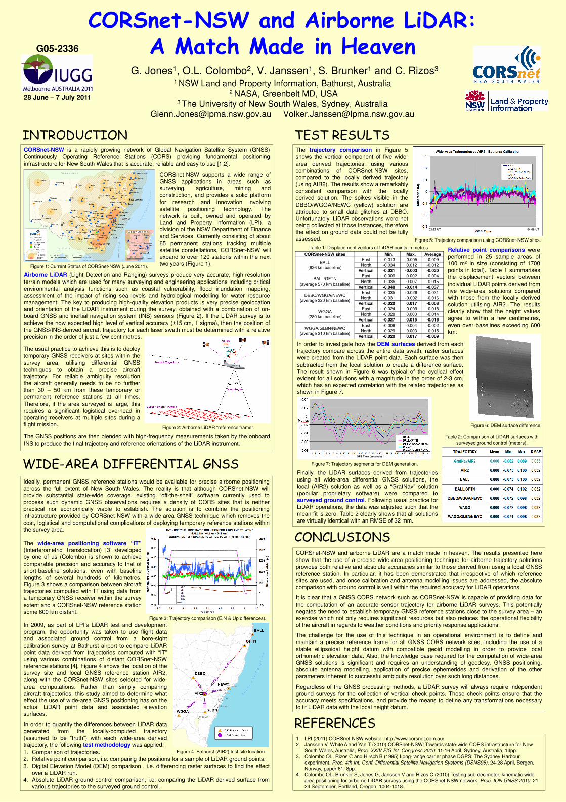
TEST RESULTSThe trajectory comparison in Figure 5shows the vertical component of five wide-

infrastructure for New South Wales that is accurate, reliable and easy to use [1,2].

Airborne LiDAR (Light Detection and Ranging) surveys produce very accurate, high-resolutionterrain models which are used for many surveying and engineering applications including criticalenvironmental analysis functions such as coastal vulnerability, flood inundation mapping,assessment of the impact of rising sea levels and hydrological modelling for water resourcemanagement. The key to producing high-quality elevation products is very precise geolocationand orientation of the LiDAR instrument during the survey, obtained with a combination of on-board GNSS and inertial navigation system (INS) sensors (Figure 2). If the LiDAR survey is toachieve the now expected high level of vertical accuracy (±15 cm, 1 sigma), then the position of

area derived trajectories, using variouscombinations of CORSnet-NSW sites,compared to the locally derived trajectory(using AIR2). The results show a remarkablyconsistent comparison with the locallyderived solution. The spikes visible in theDBBO/WGGA/NEWC (yellow) solution areattributed to small data glitches at DBBO.Unfortunately, LiDAR observations were notbeing collected at those instances, thereforethe effect on ground data could not be fullyassessed.

CORSnet-NSW supports a wide range ofGNSS applications in areas such assurveying, agriculture, mining andconstruction, and provides a solid platformfor research and innovation involvingsatellite positioning technology. Thenetwork is built, owned and operated byLand and Property Information (LPI), adivision of the NSW Department of Financeand Services. Currently consisting of about65 permanent stations tracking multiplesatellite constellations, CORSnet-NSW willexpand to over 120 stations within the nexttwo years (Figure 1).

Figure 1: Current Status of CORSnet-NSW (June 2011).

Figure 5: Trajectory comparison using CORSnet-NSW sites.

Relative point comparisons wereperformed in 25 sample areas of100 m2 in size (consisting of 1700points in total). Table 1 summarisesthe displacement vectors betweenindividual LiDAR points derived fromfive wide-area solutions comparedwith those from the locally derivedsolution utilising AIR2. The resultsclearly show that the height valuesagree to within a few centimetres,

Table 1: Displacement vectors of LiDAR points in metres.

CORSnet-NSW sites Min. Max. Average

BALL(626 km baseline)

East -0.013 -0.005 -0.009

North -0.034 0.012 -0.012

Vertical -0.031 -0.003 -0.020

BALL/GFTN(average 570 km baseline)

East -0.009 0.002 -0.004

North -0.036 0.007 -0.015

Vertical -0.048 -0.014 -0.037

DBBO/WGGA/NEWC(average 220 km baseline)

East -0.035 -0.026 -0.031

North -0.031 -0.002 -0.016

Vertical -0.020 0.017 -0.008

WGGA(280 km baseline)

East -0.024 -0.009 -0.018

North -0.028 0.000 -0.014

Vertical -0.027 0.015 -0.016

02:32 UT 04:06 UT

Ideally, permanent GNSS reference stations would be available for precise airborne positioning

achieve the now expected high level of vertical accuracy (±15 cm, 1 sigma), then the position ofthe GNSS/INS-derived aircraft trajectory for each laser swath must be determined with a relativeprecision in the order of just a few centimetres.

The GNSS positions are then blended with high-frequency measurements taken by the onboardINS to produce the final trajectory and reference orientations of the LiDAR instrument.

WIDE-AREA DIFFERENTIAL GNSS

Figure 2: Airborne LiDAR “reference frame”.

The usual practice to achieve this is to deploytemporary GNSS receivers at sites within thesurvey area, utilising differential GNSStechniques to obtain a precise aircrafttrajectory. For reliable ambiguity resolutionthe aircraft generally needs to be no furtherthan 30 – 50 km from these temporary orpermanent reference stations at all times.Therefore, if the area surveyed is large, thisrequires a significant logistical overhead inoperating receivers at multiple sites during aflight mission.

agree to within a few centimetres,even over baselines exceeding 600km.

Vertical -0.027 0.015 -0.016

WGGA/GLBN/NEWC(average 210 km baseline)

East -0.006 0.004 -0.002

North -0.029 0.003 -0.015

Vertical -0.020 0.017 -0.009

In order to investigate how the DEM surfaces derived from eachtrajectory compare across the entire data swath, raster surfaceswere created from the LiDAR point data. Each surface was thensubtracted from the local solution to create a difference surface.The result shown in Figure 6 was typical of the cyclical effectevident for all solutions with a magnitude in the order of 2-3 cm,which has an expected correlation with the related trajectories asshown in Figure 7.

Figure 6: DEM surface difference.

Figure 7: Trajectory segments for DEM generation.

Finally, the LiDAR surfaces derived from trajectoriesusing all wide-area differential GNSS solutions, the

Table 2: Comparison of LiDAR surfaces with

surveyed ground control (meters).

GPS Time (seconds)

Ideally, permanent GNSS reference stations would be available for precise airborne positioningacross the full extent of New South Wales. The reality is that although CORSnet-NSW willprovide substantial state-wide coverage, existing “off-the-shelf” software currently used toprocess such dynamic GNSS observations requires a density of CORS sites that is neitherpractical nor economically viable to establish. The solution is to combine the positioninginfrastructure provided by CORSnet-NSW with a wide-area GNSS technique which removes thecost, logistical and computational complications of deploying temporary reference stations withinthe survey area.

CONCLUSIONS

CORSnet-NSW and airborne LiDAR are a match made in heaven. The results presented hereshow that the use of a precise wide-area positioning technique for airborne trajectory solutionsprovides both relative and absolute accuracies similar to those derived from using a local GNSSreference station. In particular, it has been demonstrated that irrespective of which referencesites are used, and once calibration and antenna modelling issues are addressed, the absolutecomparison with ground control is well within the required accuracy for LiDAR operations.

It is clear that a GNSS CORS network such as CORSnet-NSW is capable of providing data forthe computation of an accurate sensor trajectory for airborne LiDAR surveys. This potentiallynegates the need to establish temporary GNSS reference stations close to the survey area – anexercise which not only requires significant resources but also reduces the operational flexibilityof the aircraft in regards to weather conditions and priority response applications.

The challenge for the use of this technique in an operational environment is to define andmaintain a precise reference frame for all GNSS CORS network sites, including the use of a

The wide-area positioning software “IT”(Interferometric Translocation) [3] developedby one of us (Colombo) is shown to achievecomparable precision and accuracy to that ofshort-baseline solutions, even with baselinelengths of several hundreds of kilometres.Figure 3 shows a comparison between aircrafttrajectories computed with IT using data froma temporary GNSS receiver within the surveyextent and a CORSnet-NSW reference stationsome 600 km distant.

In 2009, as part of LPI’s LiDAR test and developmentprogram, the opportunity was taken to use flight dataand associated ground control from a bore-sight

Figure 3: Trajectory comparison (E,N & Up differences).

using all wide-area differential GNSS solutions, thelocal (AIR2) solution as well as a “GrafNav” solution(popular proprietary software) were compared tosurveyed ground control. Following usual practice forLiDAR operations, the data was adjusted such that themean fit is zero. Table 2 clearly shows that all solutionsare virtually identical with an RMSE of 32 mm.

1. Comparison of trajectories.2. Relative point comparison, i.e. comparing the positions for a sample of LiDAR ground points.3. Digital Elevation Model (DEM) comparison , i.e. differencing raster surfaces to find the effect

over a LiDAR run.4. Absolute LiDAR ground control comparison, i.e. comparing the LiDAR-derived surface from

various trajectories to the surveyed ground control.

maintain a precise reference frame for all GNSS CORS network sites, including the use of astable ellipsoidal height datum with compatible geoid modelling in order to provide localorthometric elevation data. Also, the knowledge base required for the computation of wide-areaGNSS solutions is significant and requires an understanding of geodesy, GNSS positioning,absolute antenna modelling, application of precise ephemerides and derivation of the otherparameters inherent to successful ambiguity resolution over such long distances.

Regardless of the GNSS processing methods, a LiDAR survey will always require independentground surveys for the collection of vertical check points. These check points ensure that theaccuracy meets specifications, and provide the means to define any transformations necessaryto fit LiDAR data with the local height datum.

REFERENCES1. LPI (2011) CORSnet-NSW website: http://www.corsnet.com.au/.2. Janssen V, White A and Yan T (2010) CORSnet-NSW: Towards state-wide CORS infrastructure for New

South Wales, Australia, Proc. XXIV FIG Int. Congress 2010, 11-16 April, Sydney, Australia, 14pp.3. Colombo OL, Rizos C and Hirsch B (1995) Long-range carrier phase DGPS: The Sydney Harbour

experiment, Proc. 4th Int. Conf. Differential Satellite Navigation Systems (DSNS95), 24-28 April, Bergen, Norway, paper 61, 8pp.

4. Colombo OL, Brunker S, Jones G, Janssen V and Rizos C (2010) Testing sub-decimeter, kinematic wide-

area positioning for airborne LiDAR surveys using the CORSnet-NSW network, Proc. ION GNSS 2010, 21-24 September, Portland, Oregon, 1004-1018.

Figure 4: Bathurst (AIR2) test site location.

and associated ground control from a bore-sightcalibration survey at Bathurst airport to compare LiDARpoint data derived from trajectories computed with “IT”using various combinations of distant CORSnet-NSWreference stations [4]. Figure 4 shows the location of thesurvey site and local GNSS reference station AIR2,along with the CORSnet-NSW sites selected for wide-area computations. Rather than simply comparingaircraft trajectories, this study aimed to determine whateffect the use of wide-area GNSS positioning has on theactual LiDAR point data and associated elevationsurfaces.

In order to quantify the differences between LiDAR datagenerated from the locally-computed trajectory(assumed to be “truth”) with each wide-area derivedtrajectory, the following test methodology was applied: