coseismic fault-related fold model, growth structure,...
TRANSCRIPT
Coseismic fault-related fold model, growth structure, and
the historic multisegment blind thrust earthquake on the
basement-involved Yoro thrust, central Japan
Tatsuya Ishiyama,1 Karl Mueller,2 Hiroshi Sato,3 and Masami Togo4
Received 6 March 2006; revised 16 January 2007; accepted 5 February 2007; published 28 March 2007.
[1] We use high-resolution seismic reflection profiles, boring transects, and mapping offold scarps that deform late Quaternary and Holocene sediments to define the kinematicevolution, subsurface geometry, coseismic behavior, and fault slip rates for an active,basement-involved blind thrust system in central Japan. Coseismic fold scarps on theYoro basement-involved fold are defined by narrow fold limbs and angular hinges onseismic profiles, suggesting that at least 3.9 km of fault slip is consumed by wedge thrustfolding in the upper 10 km of the crust. The close coincidence and kinematic link betweenfolded horizons and the underlying thrust geometry indicate that the Yoro basement-involved fold has accommodated slip at an average rate of 3.2 ± 0.1 mm/yr on a shallowlywest dipping thrust fault since early Pleistocene time. Past large-magnitudeearthquakes, including an historic M 7.7 event in A.D. 1586 that occurred on the Yoroblind thrust, are shown to have produced discrete folding by curved hinge kink bandmigration above the eastward propagating tip of the wedge thrust. Coseismic fold scarpsformed during the A.D. 1586 earthquake can be traced along the en echelon activefolds that extend for at least 60 km, in spite of different styles of folding along theapparently hard-linked Nobi-Ise blind thrust system. We thus emphasize the importance ofthis multisegment earthquake rupture across these structures and the potential risk forsimilar future events in en echelon active fold and thrust belts.
Citation: Ishiyama, T., K. Mueller, H. Sato, and M. Togo (2007), Coseismic fault-related fold model, growth structure, and the
historic multisegment blind thrust earthquake on the basement-involved Yoro thrust, central Japan, J. Geophys. Res., 112, B03S07,
doi:10.1029/2006JB004377.
1. Introduction
[2] Long-term and coseismic growth of active folds canbe used as a proxy for slip produced during earthquakes onblind thrusts. Studies of many active fold and thrust beltssuch as those in Taiwan and the Himalaya show thatdeformation of fluvial terraces within transverse channelscan also be used to define styles and rates of active folding,in effect providing finite strain markers of different ageacross these structures [Philip and Meghraoui, 1983;Rockwell et al., 1984, 1988; Bullard and Lettis, 1993;Molnar et al., 1994; Burbank et al., 1996; Shaw andSuppe, 1996; Mueller and Suppe, 1997; Benedetti et al.,2000, 2003; Lave and Avouac, 2000; Thompson et al.,2002; Dolan et al., 2003; Ishiyama et al., 2004; Bennettet al., 2005; Shyu et al., 2006; Scharer et al., 2006]. In
particular, studies by Lave and Avouac [2000], Ishiyama etal. [2004] and other papers in this special section show thatfolded fluvial terraces can be related to overall fold geometryand the kinematics of migrating axial surfaces or wholesalerotation of fold limbs. This can then be used to identify themechanisms that act to build fault-related folds, determinethe geometry of blind thrusts and track the accrual of slip onthem. This approach points to the significance of tectoniclandforms and their utility in recording growth of activefolds at different timescales, providing a geomorphic recordof slip on underlying blind thrusts. Moreover, because blindthrusts do not reach the ground surface, the kinematiclinkage between fold scarps and underlying thrusts isimplicit and hence must be carefully documented in orderto validate estimates of fault slip as provided by inversionsof seismological or geodetic data [cf. Freymueller et al.,1994; Johnson et al., 2001; Dominguez et al., 2003]. This isalso of obvious importance for assessing the styles of surfacedeformation produced along active folds for seismic hazardsanalysis in urbanized areas [Mueller et al., 1999; Suppe etal., 2000; Champion et al., 2001; Hung and Suppe, 2002;Dolan et al., 2003; Ishiyama et al., 2004].
[3] Kinematic models of fault-related folds, which arebroadly assigned to those that grow by fault bend [Suppe,1983; Medwedeff, 1992; Medwedeff and Suppe, 1997] and
JOURNAL OF GEOPHYSICAL RESEARCH, VOL. 112, B03S07, doi:10.1029/2006JB004377, 2007ClickHere
for
FullArticle
1Active Fault Research Center, Geological Survey of Japan, NationalInstitute of Advanced Industrial Science and Technology, Tsukuba, Japan.
2Department of Geological Sciences, University of Colorado, Boulder,Colorado, USA.
3Earthquake Research Institute, University of Tokyo, Tokyo, Japan.4Department of Geoscience, Hosei University, Machida, Japan.
Copyright 2007 by the American Geophysical Union.0148-0227/07/2006JB004377$09.00
B03S07 1 of 22
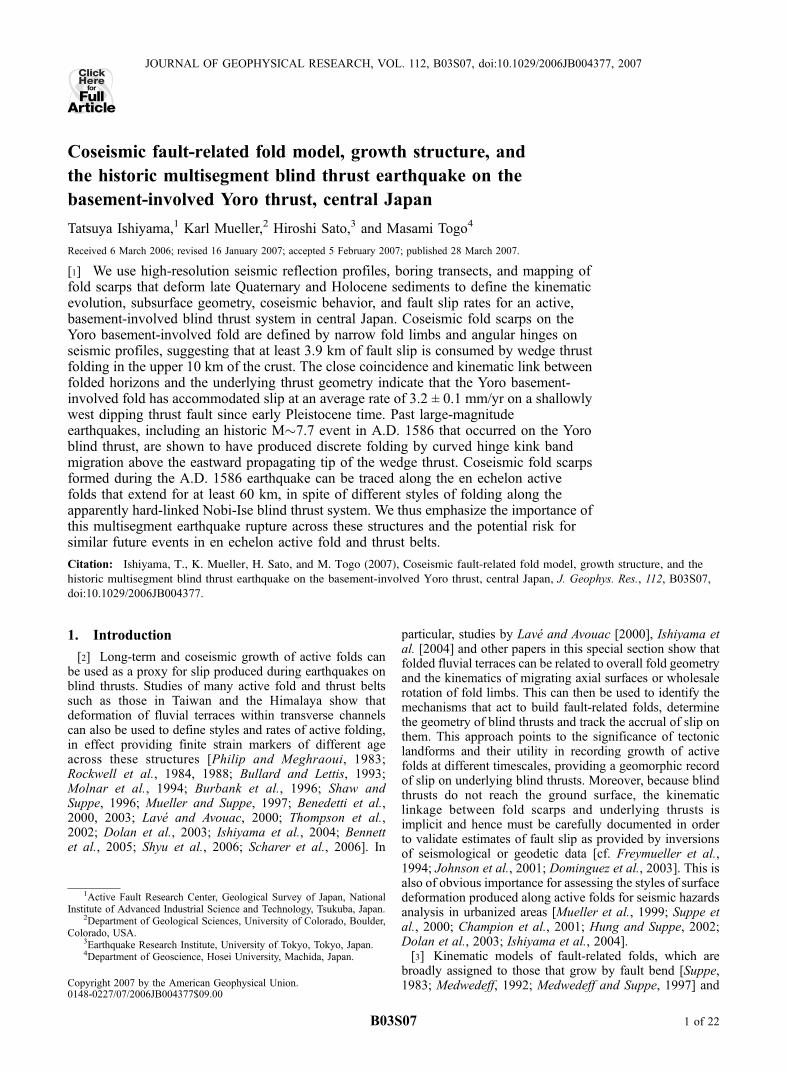
trishear fault propagation mechanisms [Erslev, 1991; Hardyand Ford, 1997; Allmendinger, 1998], generally predictseveral different styles of surface strain related to overallfold and blind thrust geometry. Stratigraphic growth archi-tecture [Suppe et al., 1992; Shaw and Suppe, 1994; Suppe etal., 1997] has also provided considerable insight into foldkinematics and their growth histories. A common style ofcoseismic fault-related folding includes growth of a foldscarp by shear above a blind thrust fault tip that propagatesupward with increased displacement. Fold scarps formed asforelimbs of fault propagation folds [Erslev, 1991;Allmendinger, 1998] are documented for a number of thrustfaults that have ruptured in large historic or prehistoricearthquakes (Figures 1a and 1d) [Sato et al., 1997;Champion
et al., 2001;Dolan et al., 2003; Lee et al., 2004]. Other stylesof coseismic folding can be distinguished by the location ofactive folding of the ground surface relative to the geometryof the fold limb. Fold scarps that grow at their crests by kinkband migration are often related to folding across the top ofa blind thrust ramp [Suppe, 1983; Pratt et al., 2002; Shaw etal., 2002; Dolan et al., 2003] (Figures 1b and 1e). Alterna-tively, fold scarps that grow by surface folding across asynclinal axial surface, which we describe here for the Yorofault, can often be related to wedge thrust faulting, wheresediment and landforms is drawn upward onto the forelimb[Medwedeff, 1992; Mueller and Suppe, 1997; Ishiyama etal., 2004] (Figures 1c and 1f). Secondary strain is also acommon aspect of coseismic fault-related folding and
Figure 1. Schematic cross sections showing kinematic link between coseismic fold/fault scarps andgeometries of underling thrusts in case of (a) emergent thrust ramp, (b) single-step fault bend fold [Suppe,1983], and (c) wedge thrust fold [Medwedeff, 1992]. (d) Seismic reflection profile across a coseismic faultscarp during A.D. 1896 Riku-u earthquake (M 7) above an emergent thrust ramp [Sato et al., 1997].(e) Cross section across the Puente Hills thrust shows coseismic fold scarp above a ramp flat thrusttrajectory [Shaw et al., 2002; Dolan et al., 2003]. (f) Cross section across Kuwana anticline in centralJapan shows A.D. 1586 coseismic fold scarp above a doubly vergent thrust wedge [Ishiyama et al.,2004]. Open-headed arrows indicate folding vectors.
B03S07 ISHIYAMA ET AL.: COSEISMIC FOLDING OF A WEDGE THRUST FOLD
2 of 22
B03S07
includes small-scale extensional faulting [Kelson et al.,1996; Champion et al., 2001; Philip et al., 1992] andflexural slip faulting [Philip and Meghraoui, 1983; Ishiyamaet al., 2004]. These features result from strain accumula-tion within forelimbs associated with coseismic slip butare not otherwise directly linked with slip on underlyingblind thrusts or active axial surfaces extending from them.
[4] We argue therefore that careful description of coseis-mic fold scarps, coupled with data sets that define largerfold structure at different scales provides unambiguousstructural solutions. Using this method, Ishiyama et al.[2004] showed that Kuwana anticline in the Nobi-Ise faultzone (NIFZ) in central Japan has formed as a wedge thrustfold and accommodated shortening during a historic blindthrust earthquake in A.D. 1586, which is expressed as anarrow kink band in late Holocene sediments.
[5] In this paper, we present additional data and newstructural models of coseismic folding and fault-related foldof the Yoro basement-involved structure within the NIFZ incentral Japan (Figure 2). Here we focus on coseismic foldscarps along an active fold and thrust belt that deform well-
dated late Quaternary deposits, recording strain rates atdifferent timescales and paleoearthquakes. Subsurface foldgeometry is first constrained by high-resolution seismicprofiles that image shallow (to depth of 2.5 km) and veryshallow (to depth of 50 m) Pliocene, Pleistocene, andHolocene deposits. Secondly, detailed stratigraphy and ageconstraints of strata defined in boreholes drilled across lateHolocene fold scarps reveal the near-surface (to depth of
10 m) geometry of folded strata and timing of coseismicfold growth events that are correlated with earthquakesrecorded in historic documents [Usami, 2003] and olderpaleoearthquakes. Third, two seismic reflection profilesacross the forelimb and backlimb of the fold illuminatesubsurface thrust trajectories beneath the basement-involvedfold. This multiscale data set provides relatively unambig-uous comparison between coseismic fold scarps generatedby historically documented earthquakes with underlyingfault-related fold geometry. Our work thus adds to thegrowing number of studies that test assumptions for foldkinematics by documentation of active structures known togrow in large blind thrust earthquakes [Suppe et al., 2000;
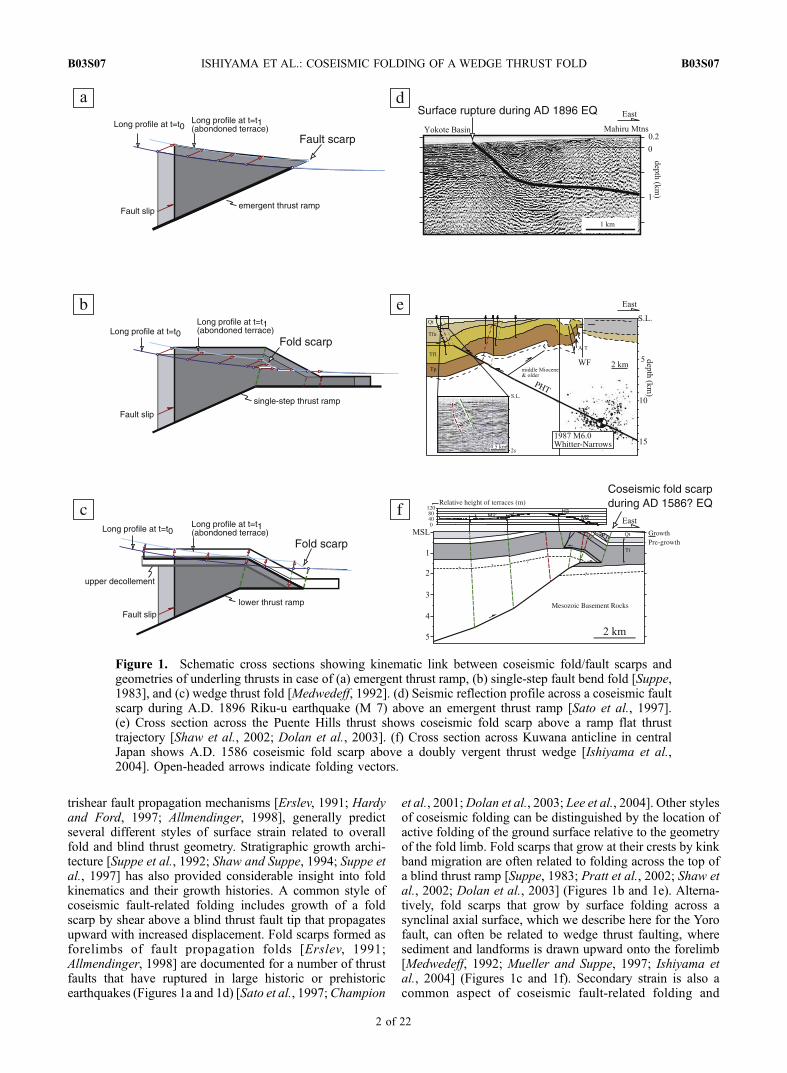
Figure 2. (a) Shaded relief map based on 250 m digital elevation model (DEM) [Kishimoto, 2000]showing the topography and distribution of active faults within the Kinki region, central Japan. Locationsof active faults are from Nakata and Imaizumi [2002]. Red, orange, and gray lines mark active faults thatare precisely located, approximately located, and inferred, respectively. Barbs denote hanging walls ofactive thrusts. Arrows indicate slip directions of strike-slip faults. Plate convergence rate is from Wei andSeno [1998]. Abbreviations for metropolitan areas are KB, Kobe; OK, Osaka; KT, Kyoto; NG, Nagoya.(b) Shaded relief map based on a 6-m DEM showing the locations of active thrusts in the northern portionof the NIFZ. Barbs indicate hanging walls of active thrusts.
B03S07 ISHIYAMA ET AL.: COSEISMIC FOLDING OF A WEDGE THRUST FOLD
3 of 22
B03S07
Hung and Suppe, 2002; Dolan et al., 2003; Ishiyama et al.,2004]. The Yoro structure is particularly interesting becauseof the behavior during the A.D. 1586 earthquake, whichapparently ruptured across at least two, and probably threeseparate fault-related folds in an en echelon pattern at thesurface.
2. Regional Setting of the YoroBasement-Involved Fold
[6] The Island of Honshu in central Japan is an activelydeforming island arc with a complex array of strike slip andthrust faults that accommodate intraplate strain above sub-ducting slabs of oceanic lithosphere. These fault systemsoften bound, or lie within Neogene sedimentary basins thatare densely urbanized [Research Group for Active Faults,1991; Okada and Togo, 2000; Ikeda et al., 2002; Nakataand Imaizumi, 2002] (Figure 2). The Kinki region, locatedat central southwestern Honshu Island, is also characterizedby an array of north trending thrust sheets, which havedeformed Neogene basin deposits [Yeats et al., 1997; Ikedaet al., 2002; Ishiyama et al., 2004]. The Kinki region liesbetween a Mesozoic accretionary wedge in central south-western Japan and high-grade metamorphic rocks boundedby the Median Tectonic Line (MTL), a major dextral faultsystem to the south. E-W contraction north of the MTL inthis region has occurred during late Cenozoic time wherestrain is partitioned above the obliquely subducting Philip-pine Sea plate (Figure 2a).
[7] The NIFZ consists of a 110-km-long array of activeeast verging thrusts that deform Neogene basins at theeastern edge of the Kinki region. The northern half of thisthrust system includes (from north to south) the Yorobasement-involved fold, Kuwana anticline [Ishiyama etal., 2004] and Yokkaichi anticline to the south (Figure 2band 3). Shortening in this region also occurs along theFumotomura and Ichishi faults, which contain the SuzukaMountains in their hanging walls. Structural and surfacerelief of folds in the frontal NIFZ decreases from north tosouth.
[8] The Yoro basement-involved fold extends for 20 kmin the northern NIFZ and separates the modern Nobi basinin the east from a piggyback portion of the basin and theSuzuka Mountains in the west (Figures 2b and 3). The YoroMountains form the stripped core of the largest structure inthe NIFZ and expose Triassic-Jurassic strata that are trans-lated eastward on a blind thrust above a 1500-m-thicksequence of Pliocene-Pleistocene strata deposited in theNobi basin (Figures 4, 5, 6, and 7). The blind thrustunderlying the Yoro Mountains is a part of a larger systemof east vergent faults that includes the Ichishi thrust to theeast. The Ichishi fault is the northern portion of the 20-km-long Fumotomura fault [Ishiyama et al., 1999] that extendsalong the length of the northern NIFZ.
[9] The Suzuka Mountains, which lie in the hanging wallof the Fumotomura fault, have been thrust over a 1000-m-thick sequence of older, Pliocene–lower Pleistocene stratain the paleo-Nobi basin (Figures 8 and 9). In contrast to theFumotomura and Yoro fault, the Ichishi thrust generally hasnot recently formed fold scarps along it, suggesting that ithas been essentially inactive in late Pleistocene time. Thusthe Yoro and Ichishi thrust faults can be interpreted as a
forward breaking imbricate thrust system, although this isnot the case further south where the Fumotomura faultappears to be presently active in addition to the frontalKuwana and Yokkaichi anticlines.
3. Stratigraphy of the Nobi Basin and ItsPiggyback Remnant
[10] As described in detail by Ishiyama et al. [2004], theNobi basin is underlain by a >1500-m-thick succession ofPliocene to Holocene sediments. We used stratigraphycharacterized in 600- and 1500-m-deep, continuously coredboreholes (GS-NB1 and Kz) in the Nobi basin (Sugai etal.’s [1999b] Figure 4; see their locations in Figure 3) todefine the ages of reflectors in several seismic profiles.Pregrowth strata of Neogene age include fluvial and lacus-trine sediments of the late Pliocene–early Pleistocene TokaiGroup [Takemura, 1985; Yoshida et al., 1991]. The TokaiGroup in the Nobi basin is about 1500- to 2000-m-thick[Committee for Subsurface Structure of the Nobi Plain,2001]. Dating of volcanic ash layers by the fission trackmethod indicates that the Tokai Group was deposited fromcirca 2.8 Ma to 1.0 Ma [Takemura, 1985; Yoshida et al.,1991] (Figure 4).
[11] Seismic reflection data presented later in this paper(Figure 5, 6, 7, and 9) suggest that reflectors correlated withlate Pliocene–early Pleistocene sandstone and mudstonebeneath the Nobi basin were deposited prior to uplift ofthe fold. Evidence for the pregrowth nature of these strataincludes the continuity of units with a consistent thicknessin the footwall syncline below, and in a piggyback basinuplifted onto the backlimb of the Yoro basement-involvedfold.
[12] Growth strata that are folded above the propagatingtip of the Yoro thrust consist of alternating coarse-grainedgravel, sand and mud of the Owari Group [Sakamoto et al.,1986; Yoshida et al., 1991; Furusawa, 1990; Sugai et al.,1999b] (Figure 4). Recent analysis of cores based onlithostratigraphy, magnetostratigraphy, and tephrastratigra-phy suggests that the Owari Group has been depositedduring middle-late Quaternary time and contains a volcanicash layer dated at circa 0.9 Ma in its lowest part [Sugai etal., 1999b]. A 50-m-thick sequence of Holocene strata (theNanyo Formation) overlies the Owari Group as defined byseismic profiles, borehole stratigraphy and geochronology.The uppermost section of the Nanyo Formation onlaps theeastern edge of the forelimb of the Yoro basement-involvedfold and thus records its growth history during the lateHolocene.
[13] The piggyback basin between the Yoro and SuzukaMountains is filled with a 1000-m-thick sequence of allu-vium that is correlated with the upper Pliocene to lowerPleistocene section of the Tokai Group in the modern Nobibasin based on lithostratigraphy and tephrostratigraphy[Yoshida, 1988] (Figures 8 and 9). In contrast with themodern Nobi basin, the piggyback basin unit apparentlylacks middle Pleistocene to Holocene strata but is uncon-formably overlain, or capped by flights of late Pleistocenefluvial strath terraces. Distal alluvial channel-floodplainfacies of sedimentary units in the piggyback basin aregenerally correlative to similar Nobi basin units except forthe uppermost clastic deposits. We interpret the general
B03S07 ISHIYAMA ET AL.: COSEISMIC FOLDING OF A WEDGE THRUST FOLD
4 of 22
B03S07
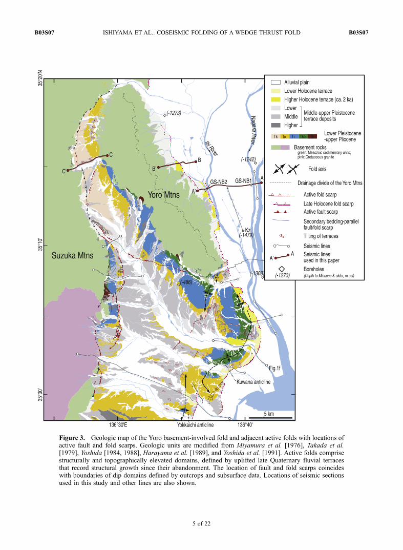
Figure 3. Geologic map of the Yoro basement-involved fold and adjacent active folds with locations ofactive fault and fold scarps. Geologic units are modified from Miyamura et al. [1976], Takada et al.[1979], Yoshida [1984, 1988], Harayama et al. [1989], and Yoshida et al. [1991]. Active folds comprisestructurally and topographically elevated domains, defined by uplifted late Quaternary fluvial terracesthat record structural growth since their abandonment. The location of fault and fold scarps coincideswith boundaries of dip domains defined by outcrops and subsurface data. Locations of seismic sectionsused in this study and other lines are also shown.
B03S07 ISHIYAMA ET AL.: COSEISMIC FOLDING OF A WEDGE THRUST FOLD
5 of 22
B03S07
correlation of strata in the Nobi basin with its now separatedportion to the west as indicating that these strata arepregrowth (relative to Yoro) in nature.
4. Coseismic Fold Scarp Structure of theYoro Thrust
4.1. Geomorphology of the Coseismic Fold Scarp
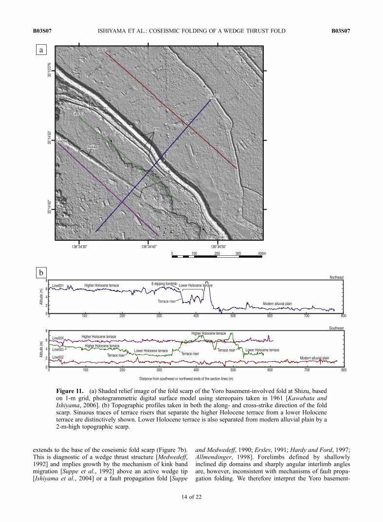
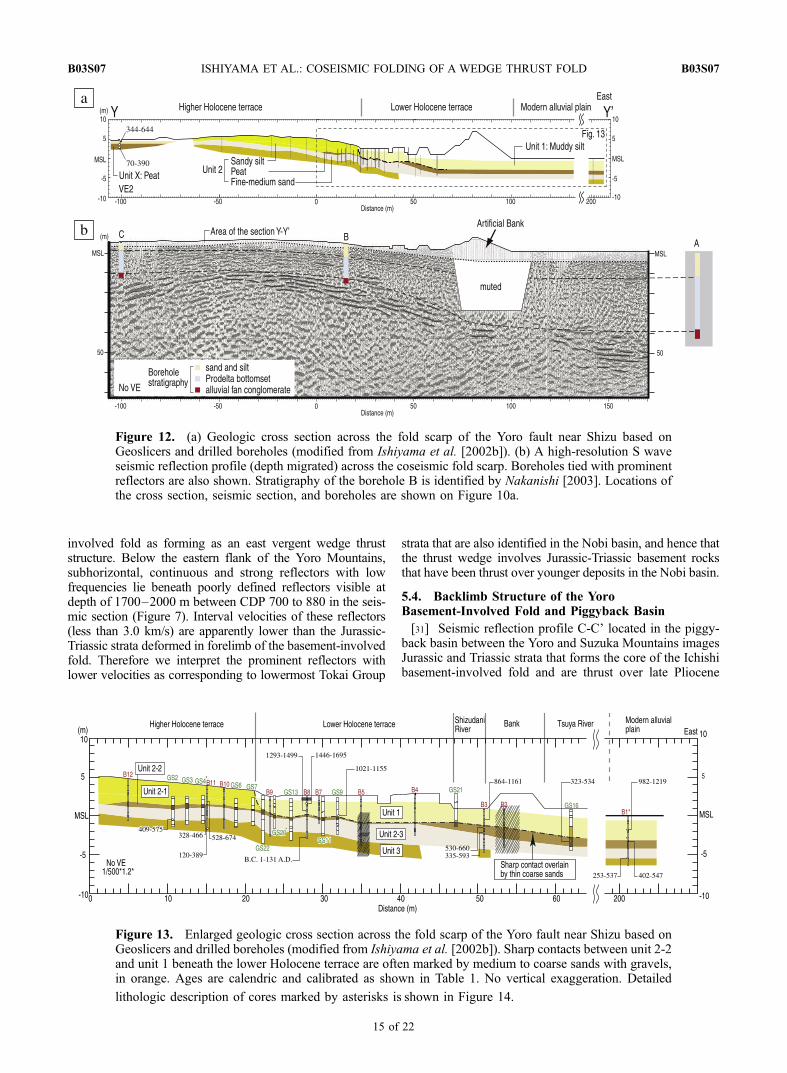
[14] The subtle, east facing scarps that offset late Holo-cene sediments about 5 m on the east flank of the Yoromountains are apparent on 1:10,000 aerial photographstaken in 1940s by the U.S. military in reconstruction eraJapan and modern 1:2,500 scale topographic maps [Togo,2000] (Figure 10). Detailed mapping of the fold scarp atShizu based on a 1-m-grid digital surface model (DSM)generated by photogrammetry using stereopairs taken in the1960s prior to recent urbanization suggests that the scarpsseparate higher and lower Holocene terraces from themodern alluvial plain (Figure 11) [Kawabata and Ishiyama,2006]. Whereas the extensive higher Holocene terracegently dips eastward at its eastern end, a remnant of thelower Holocene terrace is subhorizontal. These two terracesare separated by east facing scarps. The sinuous trace of thescarps and a flat surface of lower Holocene terrace suggestthat the scarp can be interpreted as a terrace riser made bylateral migration of alluvial rivers, rather than by artificialmodification or cultivation.
[15] Boreholes A and B drilled at the base of the forelimbindicate that the folded strata underlying the surface scarpsrecord 14 m of vertical separation as measured from the topof middle Holocene prodelta (bottom set) deposits that werepresumably deposited on a near-horizontal bay (Figure 12)[Togo, 2000]. The prodelta unit thickens eastward by about12 m beneath the fold scarp. In addition, overlying delta andfloodplain deposits that thicken eastward by about 3 m arealso folded by about 3 m of offset. We thus interpret this lateHolocene topographic scarp as indicating a recent activefolding event with 3 m of vertical structural relief aftermiddle Holocene time beneath the fold scarp (Figure 10).
[16] Late Holocene fold scarps that deform coastal plaindeposits by 3–5 m are traced continuously along theleading edge of the NIFZ, including the Kuwana andYokkaichi anticlines [Awata and Yoshida, 1991; Togo,2000; Ikeda et al., 2002; Ishiyama et al., 2002a, 2004]
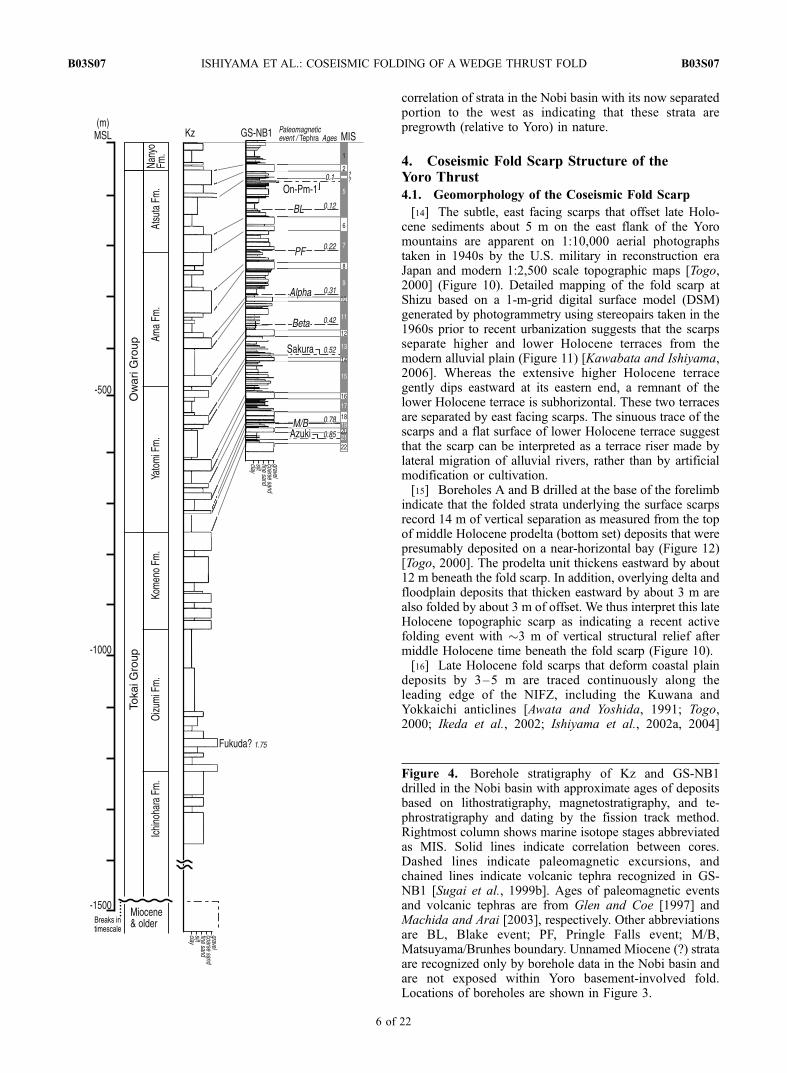
Figure 4. Borehole stratigraphy of Kz and GS-NB1drilled in the Nobi basin with approximate ages of depositsbased on lithostratigraphy, magnetostratigraphy, and te-phrostratigraphy and dating by the fission track method.Rightmost column shows marine isotope stages abbreviatedas MIS. Solid lines indicate correlation between cores.Dashed lines indicate paleomagnetic excursions, andchained lines indicate volcanic tephra recognized in GS-NB1 [Sugai et al., 1999b]. Ages of paleomagnetic eventsand volcanic tephras are from Glen and Coe [1997] andMachida and Arai [2003], respectively. Other abbreviationsare BL, Blake event; PF, Pringle Falls event; M/B,Matsuyama/Brunhes boundary. Unnamed Miocene (?) strataare recognized only by borehole data in the Nobi basin andare not exposed within Yoro basement-involved fold.Locations of boreholes are shown in Figure 3.
B03S07 ISHIYAMA ET AL.: COSEISMIC FOLDING OF A WEDGE THRUST FOLD
6 of 22
B03S07
(Figure 3). On the basis of tectonic geomorphology andstructural analysis constrained by high-resolution seismicdata, a historic earthquake that occurred on the Kuwanablind thrust system in A.D. 1586 (Tensyo earthquakeM 7.7 [Usami, 2003]) is shown to have produced coseis-mic surface deformation above both of the stacked, doublyvergent wedge tips [Ishiyama et al., 2004] that define thatpart of the NIFZ (Figure 1f).
4.2. S Wave Seismic Reflection Data Beneath theCoseismic Fold Scarp
[17] In an effort to define the detailed subsurface geom-etry of the fold scarp, we acquired shallow high-resolutionseismic reflection data across the coseismic fold scarp atShizu (Figure 12; location of the seismic line is shown inFigure 10a). An S wave vibrator source and 1-m spacinggeophones designed for S wave detection were used for the
data collection. Reflectors imaged on the seismic profilewere tied with strata defined in boreholes in the modernNobi basin [Ishiyama et al., 2002b; Nakanishi, 2003] (seetheir locations in Figures 10 and 12). Very strong (i.e., high-amplitude) and continuous reflectors lie about 40 m belowthe ground surface in the basin near the southwest end of thesection. The uppermost of these prominent reflectors isinterpreted as the top of late Pleistocene alluvial fan depositsthat are exposed west of the Shizu area (Figure 10).Radiocarbon dating suggests that the age of this stratigraphichorizon is about 15.5 ± 1.2 ka [Nakanishi, 2003].
[18] The prominent reflectors tied with the alluvial fandeposits in the boreholes are clearly folded beneath theeast facing fold scarp as indicated by the seismic profile(Figure 12b). Subhorizontal reflectors in the syncline to thenortheast are continuous with reflectors in the forelimb(Figure 12b). These strata collectively define a distinctive
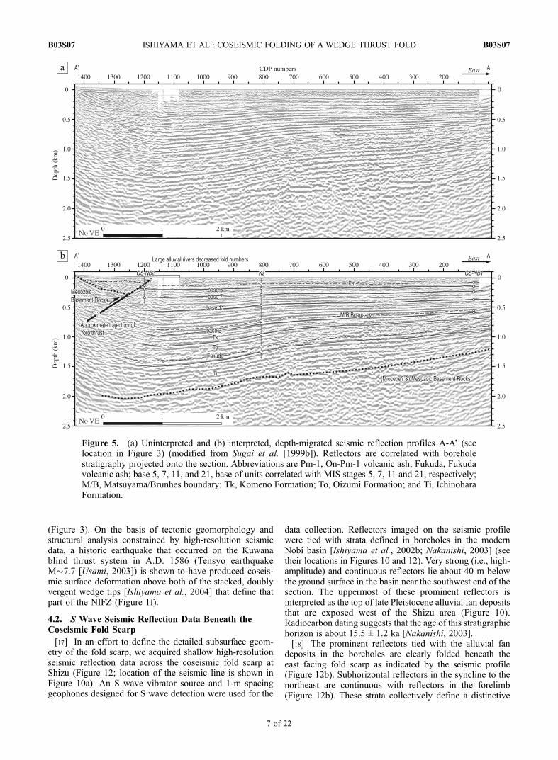
Figure 5. (a) Uninterpreted and (b) interpreted, depth-migrated seismic reflection profiles A-A’ (seelocation in Figure 3) (modified from Sugai et al. [1999b]). Reflectors are correlated with boreholestratigraphy projected onto the section. Abbreviations are Pm-1, On-Pm-1 volcanic ash; Fukuda, Fukudavolcanic ash; base 5, 7, 11, and 21, base of units correlated with MIS stages 5, 7, 11 and 21, respectively;M/B, Matsuyama/Brunhes boundary; Tk, Komeno Formation; To, Oizumi Formation; and Ti, IchinoharaFormation.
B03S07 ISHIYAMA ET AL.: COSEISMIC FOLDING OF A WEDGE THRUST FOLD
7 of 22
B03S07
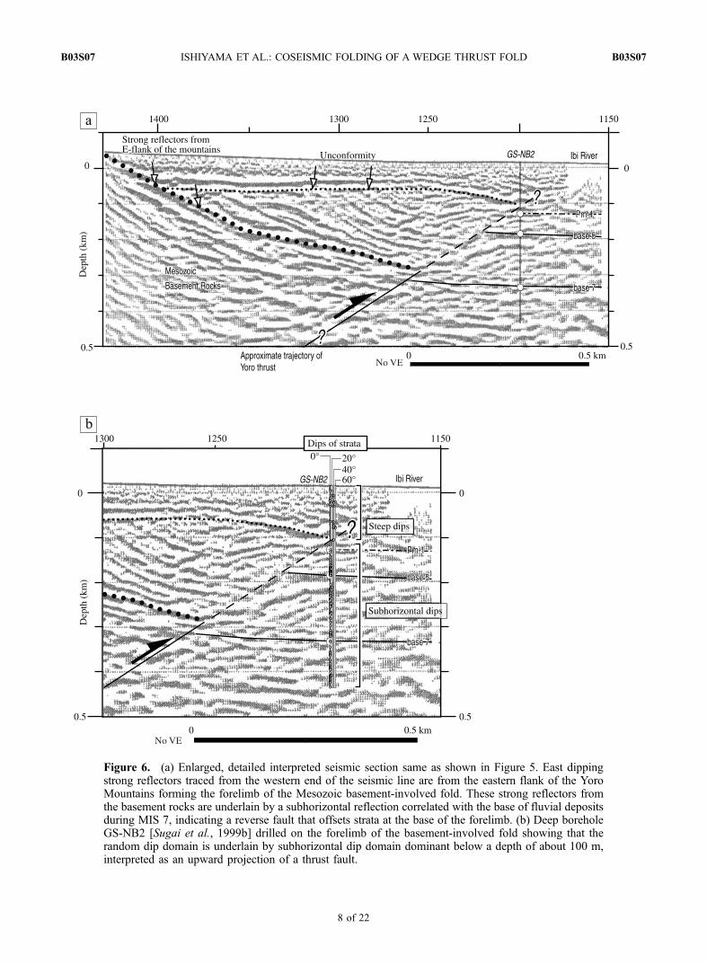
Figure 6. (a) Enlarged, detailed interpreted seismic section same as shown in Figure 5. East dippingstrong reflectors traced from the western end of the seismic line are from the eastern flank of the YoroMountains forming the forelimb of the Mesozoic basement-involved fold. These strong reflectors fromthe basement rocks are underlain by a subhorizontal reflection correlated with the base of fluvial depositsduring MIS 7, indicating a reverse fault that offsets strata at the base of the forelimb. (b) Deep boreholeGS-NB2 [Sugai et al., 1999b] drilled on the forelimb of the basement-involved fold showing that therandom dip domain is underlain by subhorizontal dip domain dominant below a depth of about 100 m,interpreted as an upward projection of a thrust fault.
B03S07 ISHIYAMA ET AL.: COSEISMIC FOLDING OF A WEDGE THRUST FOLD
8 of 22
B03S07

Figure 7. (a) Uninterpreted and (b) interpreted depth-migrated seismic profile across the forelimb of theYoro basement-involved fold acquired for this study. Location is shown on Figures 3 and 10. No verticalexaggeration. Reflectors are correlated with those in A-A’ tied with borehole stratigraphy. Abbreviationsare the same as Figure 5. Note that trajectory of the Yoro thrust for the highest level in is a preliminaryone and discussed in section 5.5.
B03S07 ISHIYAMA ET AL.: COSEISMIC FOLDING OF A WEDGE THRUST FOLD
9 of 22
B03S07
synclinal axial surface that bisects the interlimb angles,rather than a reverse fault that offsets strata at the base ofthe forelimb.
4.3. Shallow Structure of the Coseismic Fold Scarp
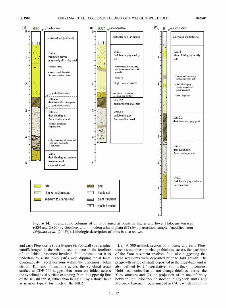
[19] We also acquired 21 cores up to 5 m long using a‘‘Geoslicer’’ [Nakata and Shimazaki, 1997; Atwater et al.,2001] and 15 cores up to 7 m long using a percussion coresampler in an east-west transect along the high-resolutionseismic line across the fold scarp at the same site [Ishiyama etal., 2002b] (Figures 12, 13, and 14). Boreholes and Geoslicerpanels penetrated a late Holocene sequence of deltafront (foreset) sand deposits, overlying peaty clay, sandy silt,and sandy clay (top set and alluvial plain) deposits above a(bottom set) prodelta unit penetrated by deeper boreholes A,B and C (Figure 12). While sandy foreset and peaty claydeposits (lower section of unit 2) are laterally continuous andcan be traced along the entire 500-m length of the transect,sandy silt (uppermost unit 2) and muddy silt deposits (unit 1)are located only beneath the higher and lower Holoceneterraces (Figure 14). Radiocarbon dating of 18 samplesobtained from the cores shows that sediment accumulationhas been continuous during the past 10,000 years with nomajor depositional hiatus (Table 1) [Ishiyama et al., 2002b],as indicated by Nakanishi [2003].
[20] Near-surface stratigraphic relations, radiocarbon dat-ing and structural restoration of folded strata point to lateHolocene and historic fold growth events at this site. Amongthe events are two recent earthquakes that postdate depositionof the peat layer (A.D. 120–660) in unit 2. The most recentevent occurred in historical time, as suggested by offset offloodplain deposits (unit 1). Considering that unit 1 iscomposed of alluvial river channel/floodplain sandy muddeposits interbedded with flat-lying thin sand layers justbeneath the lower Holocene terrace, the lower Holoceneterrace is interpreted as a depositional surface of unit 1 atthe time of river incision discussed later. Although it is notpossible to correlate unit 1 across the frontal scarp along thebank, we interpret unit 1 as comprising both the lowerHolocene terrace and alluvial plain deposits based on theiruniform lithology and similar ages (Figures 13 and 14). A2.3-m relief across the top of unit 1 thus records an upliftevent after deposition of unit 1 rather than strata draped abovean existing fold scarp. The uppermost section of unit 1contains historical material dated by radiocarbon methods(A.D. 1446–1695) that underlie the lower Holocene terrace(Figure 7). We therefore argue that this uplift episodeoccurred in historical time and can be correlated with theTensyo earthquake in A.D. 1586 [Usami, 2003].
[21] A penultimate uplift event may be suggested byfolding of unit 2 beneath the higher alluvial plain. Unit 2composed of sandy delta front (foreset) deposits and over-lying peat and sandy silt deposits are gently inclined, similarto the slope of the higher Holocene terrace. Peaty claywithin unit 2 is more deeply buried and thicker at the baseof the frontal fold scarp (i.e., the topographic boundarybetween the lower Holocene terrace and modern alluvialplain) and is folded into a more steeply dipping panellocated near the base of the fold scarp. We thus interpretthat an uplift event occurred after deposition of unit 2 (A.D.120–389) and before deposition of unit 1 (A.D. 1021–1155). This possible paleoseismic event may be correlated
with a documented earthquake in A.D. 745 (Tenpyo earth-quake M 7.9 [Usami, 2003]). We distinguish this eventfrom the most recent historic event because (1) structuralrelief of unit 2 is almost 5 m, about twice that of unit 1, and(2) flat-lying strata of unit 1 onlap the lower section of eastdipping unit 2 near the topographic boundary between theHolocene terraces above a buttress unconformity expressedby a sharp contact and an overlying thinly bedded coarse-grained sand and gravel layer, respectively. A buttressunconformity between unit 1 and 2 is consistent with aterrace riser between the lower and higher Holocene terracecomposed of unit 1 and 2. Radiocarbon age determinationsof the base of unit 1 (A.D. 1021–1155) obtained just abovethe unconformity is approximately contemporaneous with aregional sea level fall event found at several sites in theNobi basin [Umitsu, 1994], suggesting that the terrace riserand buttress unconformity resulted from a change in baselevel associated with a fall in regional sea level. Ourpaleoseismic interpretation of two historic (i.e., Tenshoand Tenpyo) earthquakes is consistent with results at othersites along the Yoro fault [Sugai et al., 1999a] and theKuwana fault [Sugai et al., 1998].
[22] Although the geometry of a stratigraphic unitbetween the prodelta (bottom set) unit and unit 2 is notdefined in detail by this study, larger structural reliefmeasured across the prodelta unit (14 m) in relation to thatof unit 2 (5 m) can be interpreted to indicate at least oneuplift event after deposition of the prodelta unit at 5.3 ka[Nakanishi, 2003] and before the end of deposition of unit 2,prior to the two recent earthquakes.
[23] The geometry of folded alluvial fan deposits imagedby the S wave seismic reflection data is consistent withnear-surface late Holocene and historic deposits in that theupward projection of the synclinal axial surface at the baseof the forelimb that deforms alluvial fan deposits coincideswith the base of the coseismic fold scarp (Figure 12). Inaddition, the steeper forelimb and gentler backlimb are alsoapparent both at the ground surface and in late Holocenedeltaic deposits. We therefore argue that the topographicscarp at this site was produced by discrete active foldingassociated with repeated large earthquakes on the blindYoro thrust during the Holocene, including the historicA.D. 1586 earthquake.
5. Deeper Subsurface Structure of the YoroBasement-Involved Fold
5.1. Seismic Reflection Data
[24] Reflectors on an existing seismic reflection profileA-A’ obtained in the Nobi basin were correlated with stratadefined by two deep boreholes in the vicinity of, and about7 km southeast of the seismic line with stratigraphic con-tacts of known age [Sugai et al., 1999b] (Figure 5, see itslocation in Figure 3). Lithologic changes (i.e., alternation ofsandstone and mudstone) defined in the boreholes are alsoconsistent with phase changes in seismic reflectors [Sugai etal., 1999b], which also supports the stratigraphic correla-tions made in our analysis. Continuous, high-amplitudereflectors are imaged 1500 m below the ground surface atthe eastern end of the seismic section, which are interpretedas the late Pliocene to early Pleistocene Tokai Group,
B03S07 ISHIYAMA ET AL.: COSEISMIC FOLDING OF A WEDGE THRUST FOLD
10 of 22
B03S07
middle to late Pleistocene Owari Group and HoloceneNanyo Formation.
[25] Another important observation of strata imaged inthe footwall syncline of the Yoro thrust includes thepresence of subparallel, gently west dipping beds of Plio-Pleistocene Tokai Group with uniform thickness of 700 mthat are overlain by westward thickening beds of OwariGroup that flatten upward with decreased depth of burial(Figure 5). We interpret this to indicate that reflectorscorrelated with the Tokai Group were deposited prior touplift of the basement-involved fold. Additional evidencefor the pregrowth nature of these strata includes theirconsistent stratigraphic thickness with correlative unitsexposed on the backlimb of the Yoro basement-involvedfold in the piggyback basin to the west.
[26] Correlation of reflectors with boreholes GS-NB1 andGS-NB2 [Sugai et al., 1999b] indicate that strong reflectorsfrom the basement rocks are underlain by a subhorizontalreflector correlated with the base of fluvial deposits duringMarine Isotope Stage (MIS) 7, suggesting that a reversefault offsets strata at the base of the forelimb (Figure 6).However, despite the good correlation of reflectors withborehole stratigraphy, section A-A’ does not resolvePleistocene-Holocene strata in enough detail to comparethe geometry of the relatively narrow coseismic fold scarpswith older growth architecture. This resulted from thelocations by wide alluvial rivers, which limited the place-ment of certain source points during acquisition of theseismic profile, resulting in lower stacking of traces nearthe fold scarp. In addition the forelimb and footwall near theunderlying thrust are poorly imaged because the seismicline ended in the middle of the forelimb. These issuesmotivated acquisition of new continuous and closely spacedseismic reflection profiles.
5.2. Acquisition of New Seismic Reflection Data
[27] Two high-resolution seismic reflection profilesacross the forelimb (B-B’), and the backlimb of the Yorobasement-involved fold and the forelimb of the Ichishibasement-involved fold (C-C’) were thus acquired as a partof this study to further image its subsurface geometry. Weused the multichannel recording system and a seismicsource (minivibrator) of the Earthquake Research Institute,University of Tokyo (Figures 7 and 9; see locations inFigure 3 for B-B’ and C-C’). A 180-channel recordingsystem GDaps-4 was used in an off-end configuration withthe nearest receiver adjacent to the source to record seismicwaves from deeper reflection points. A 10-m source andgeophone spacing was used and gives a 5-m common depthpoint (CDP) spacing on the final section B-B’ and C-C’.The nominal CDP stacking fold was 90 traces for B-B’ andC-C’. We also increased the stacking fold by repeatingsource points 5–10 times.
[28] Data processing was routine for seismic reflectiondata [cf. Yilmaz, 1987], including surface-consistent staticsby use of refractors, velocity analysis based on Normalmoveout (NMO) method and residual statics, and thesections were finally depth-converted by use of stackingvelocities. Reflectors imaged on the seismic profile weretied with strata defined in boreholes in the Nobi basin[Sugai et al., 1999b] (see their locations in Figure 3),stratigraphic contacts on the geologic maps, and volcanic
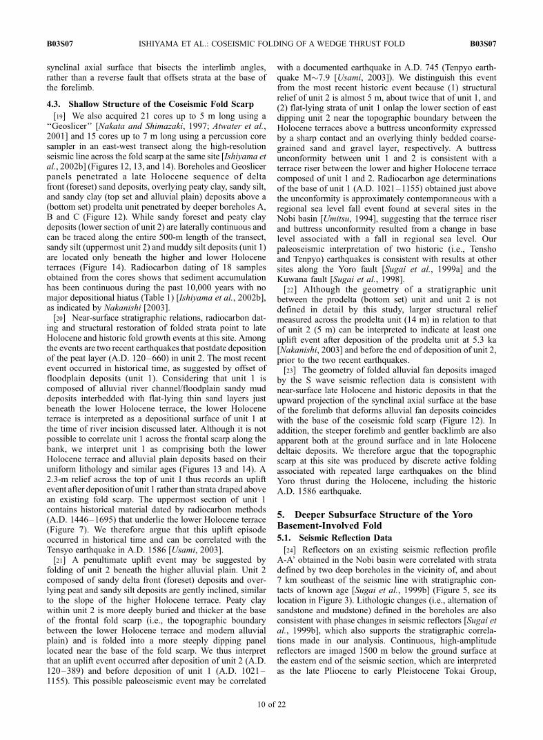
Figure 8. Stratigraphic column of piggyback basinbetween the Yoro and Suzuka Mountains, with approximateages of deposits based on tephrochronology and dating bythe fission track method [Yoshida, 1988].
B03S07 ISHIYAMA ET AL.: COSEISMIC FOLDING OF A WEDGE THRUST FOLD
11 of 22
B03S07
tephra exposed on the backlimb of the Yoro basement-involved fold and the forelimb of the Ichishi basement-involved fold.
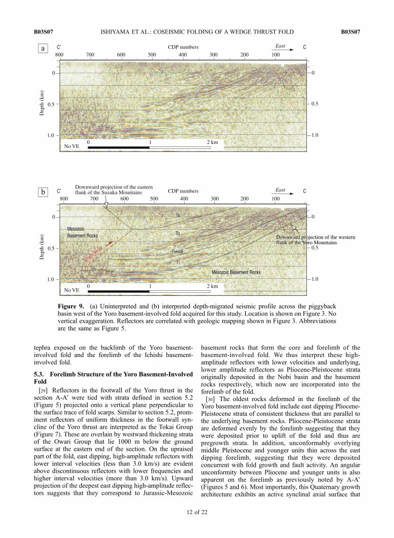
5.3. Forelimb Structure of the Yoro Basement-InvolvedFold
[29] Reflectors in the footwall of the Yoro thrust in thesection A-A’ were tied with strata defined in section 5.2(Figure 5) projected onto a vertical plane perpendicular tothe surface trace of fold scarps. Similar to section 5.2, prom-inent reflectors of uniform thickness in the footwall syn-cline of the Yoro thrust are interpreted as the Tokai Group(Figure 7). These are overlain by westward thickening strataof the Owari Group that lie 1000 m below the groundsurface at the eastern end of the section. On the upraisedpart of the fold, east dipping, high-amplitude reflectors withlower interval velocities (less than 3.0 km/s) are evidentabove discontinuous reflectors with lower frequencies andhigher interval velocities (more than 3.0 km/s). Upwardprojection of the deepest east dipping high-amplitude reflec-tors suggests that they correspond to Jurassic-Mesozoic
basement rocks that form the core and forelimb of thebasement-involved fold. We thus interpret these high-amplitude reflectors with lower velocities and underlying,lower amplitude reflectors as Pliocene-Pleistocene strataoriginally deposited in the Nobi basin and the basementrocks respectively, which now are incorporated into theforelimb of the fold.
[30] The oldest rocks deformed in the forelimb of theYoro basement-involved fold include east dipping Pliocene-Pleistocene strata of consistent thickness that are parallel tothe underlying basement rocks. Pliocene-Pleistocene strataare deformed evenly by the forelimb suggesting that theywere deposited prior to uplift of the fold and thus arepregrowth strata. In addition, unconformably overlyingmiddle Pleistocene and younger units thin across the eastdipping forelimb, suggesting that they were depositedconcurrent with fold growth and fault activity. An angularunconformity between Pliocene and younger units is alsoapparent on the forelimb as previously noted by A-A’(Figures 5 and 6). Most importantly, this Quaternary growtharchitecture exhibits an active synclinal axial surface that
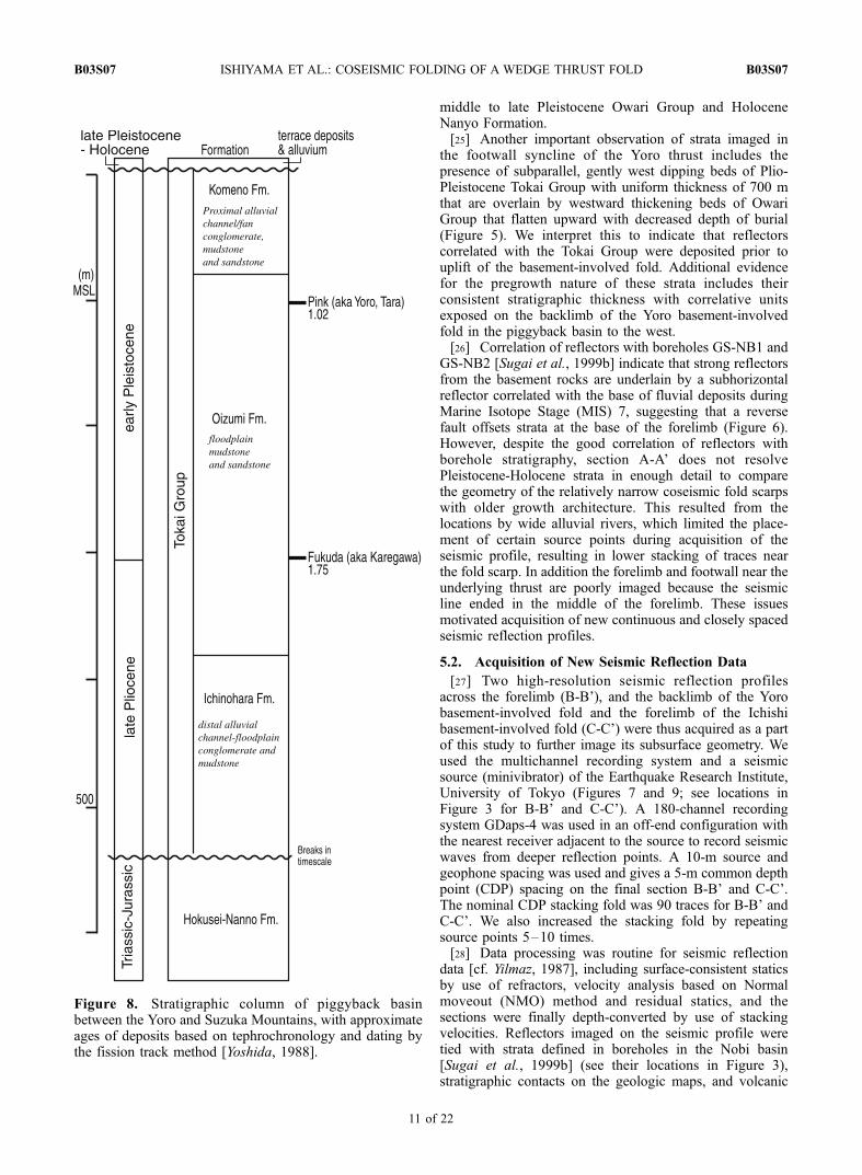
Figure 9. (a) Uninterpreted and (b) interpreted depth-migrated seismic profile across the piggybackbasin west of the Yoro basement-involved fold acquired for this study. Location is shown on Figure 3. Novertical exaggeration. Reflectors are correlated with geologic mapping shown in Figure 3. Abbreviationsare the same as Figure 5.
B03S07 ISHIYAMA ET AL.: COSEISMIC FOLDING OF A WEDGE THRUST FOLD
12 of 22
B03S07

Figure 10. (a) Detailed topography of the forelimb of the Yoro basement-involved fold (modifiedfrom Ishiyama et al. [2002b]). Topographic map with 2-m contour interval is redrawn from 1:3,000topographic maps. East verging small fold scarps at the base of the forelimb that deforms late Holoceneunits are identified. (b) Oblique aerial view of the eastern flank of the Yoro Mountains. Small fold scarplocates at the base of the forelimb of the Yoro basement-involved fold. Low-relief topography at the topof the Yoro Mountains indicates relict erosional surface formed as unconformity between Mesozoicbasement rocks and Pliocene strata. (c) Topographic profile across the entire extent of the fold scarp.
B03S07 ISHIYAMA ET AL.: COSEISMIC FOLDING OF A WEDGE THRUST FOLD
13 of 22
B03S07
extends to the base of the coseismic fold scarp (Figure 7b).This is diagnostic of a wedge thrust structure [Medwedeff,1992] and implies growth by the mechanism of kink bandmigration [Suppe et al., 1992] above an active wedge tip[Ishiyama et al., 2004] or a fault propagation fold [Suppe
and Medwedeff, 1990; Erslev, 1991; Hardy and Ford, 1997;Allmendinger, 1998]. Forelimbs defined by shallowlyinclined dip domains and sharply angular interlimb anglesare, however, inconsistent with mechanisms of fault propa-gation folding. We therefore interpret the Yoro basement-
Figure 11. (a) Shaded relief image of the fold scarp of the Yoro basement-involved fold at Shizu, basedon 1-m grid, photogrammetric digital surface model using stereopairs taken in 1961 [Kawabata andIshiyama, 2006]. (b) Topographic profiles taken in both the along- and cross-strike direction of the foldscarp. Sinuous traces of terrace risers that separate the higher Holocene terrace from a lower Holoceneterrace are distinctively shown. Lower Holocene terrace is also separated from modern alluvial plain by a2-m-high topographic scarp.
B03S07 ISHIYAMA ET AL.: COSEISMIC FOLDING OF A WEDGE THRUST FOLD
14 of 22
B03S07
involved fold as forming as an east vergent wedge thruststructure. Below the eastern flank of the Yoro Mountains,subhorizontal, continuous and strong reflectors with lowfrequencies lie beneath poorly defined reflectors visible atdepth of 1700–2000 m between CDP 700 to 880 in the seis-mic section (Figure 7). Interval velocities of these reflectors(less than 3.0 km/s) are apparently lower than the Jurassic-Triassic strata deformed in forelimb of the basement-involvedfold. Therefore we interpret the prominent reflectors withlower velocities as corresponding to lowermost Tokai Group
strata that are also identified in the Nobi basin, and hence thatthe thrust wedge involves Jurassic-Triassic basement rocksthat have been thrust over younger deposits in the Nobi basin.
5.4. Backlimb Structure of the YoroBasement-Involved Fold and Piggyback Basin
[31] Seismic reflection profile C-C’ located in the piggy-back basin between the Yoro and Suzuka Mountains imagesJurassic and Triassic strata that forms the core of the Ichishibasement-involved fold and are thrust over late Pliocene
Figure 12. (a) Geologic cross section across the fold scarp of the Yoro fault near Shizu based onGeoslicers and drilled boreholes (modified from Ishiyama et al. [2002b]). (b) A high-resolution S waveseismic reflection profile (depth migrated) across the coseismic fold scarp. Boreholes tied with prominentreflectors are also shown. Stratigraphy of the borehole B is identified by Nakanishi [2003]. Locations ofthe cross section, seismic section, and boreholes are shown on Figure 10a.
Figure 13. Enlarged geologic cross section across the fold scarp of the Yoro fault near Shizu based onGeoslicers and drilled boreholes (modified from Ishiyama et al. [2002b]). Sharp contacts between unit 2-2and unit 1 beneath the lower Holocene terrace are often marked by medium to coarse sands with gravels,in orange. Ages are calendric and calibrated as shown in Table 1. No vertical exaggeration. Detailed
lithologic description of cores marked by asterisks is shown in Figure 14.
B03S07 ISHIYAMA ET AL.: COSEISMIC FOLDING OF A WEDGE THRUST FOLD
15 of 22
B03S07
and early Pleistocene strata (Figure 9). Footwall stratigraphiccutoffs imaged in the seismic section beneath the forelimbof the Ichishi basement-involved fold indicate that it isunderlain by a shallowly (38 ) west dipping thrust fault.Continuously traced horizons within the uppermost TokaiGroup (Komeno Formation) across the synclinal axialsurface at CDP 560 suggest that strata are folded acrossthe synclinal axial surface extending from the upper tip lineof the Ichishi thrust, rather than being cut by a thrust faultas is more typical for much of the NIFZ.
[32] A 800-m-thick section of Pliocene and early Pleis-tocene strata does not change thickness across the backlimbof the Yoro basement-involved fold, also suggesting thatthese sediments were deposited prior to fold growth. Thepregrowth nature of strata deposited in the piggyback unit isalso defined by (1) correlative, 800-m-thick, lowermostNobi basin units that do not change thickness across theYoro structure and (2) the projection of an unconformitybetween the Pliocene-Pleistocene piggyback units andMesozoic basement rocks imaged in C-C’, which is contin-
Figure 14. Stratigraphic columns of units obtained at points in higher and lower Holocene terraces(GS4 and GS20) by Geoslicer and in modern alluvial plain (B1) by a percussion sampler (modified fromIshiyama et al. [2002b]). Lithologic description of units is also shown.
B03S07 ISHIYAMA ET AL.: COSEISMIC FOLDING OF A WEDGE THRUST FOLD
16 of 22
B03S07
uous with low-relief erosional surfaces on the backlimb andcrest of the fold. We thus argue that the topography of theYoro Mountains essentially defines the shape of the strippedunconformity that is overlain by pregrowth strata of theNobi basin (i.e., Pliocene–lower Pleistocene Tokai Group).
[33] Recent growth of the backlimb of the Yoro basement-involved fold is recorded by west dipping (i.e., upstream-inclined) fluvial terraces located in transverse channelsacross the eastern flank of the Suzuka Mountains. Similarto the west dipping fluvial terraces, west dipping Plioceneand early Pleistocene strata are folded and flattened in thecenter of the piggyback basin as marked by a synclinal axialsurface. Therefore the synclinal axial surface effectivelydefines the backlimb of the basement-involved fold abovethe Yoro thrust and is interpreted to be pinned at depth to asteeper ramp at depth.
5.5. Fold Geometry and Fault Slip Budget
[34] The Yoro basement-involved fold has likely formedas a wedge thrust structure above a blind thrust that steepensupward across several gentle bends (Figure 15). Smoothedtopography of the Yoro Mountains based on a 50-m digitalelevation model suggests that the elevation of high moun-tain topography can be used as a crude proxy for the shapeof the stripped unconformity between the Mesozoic base-ment rocks and the Nobi basin deposits (i.e., relict erosionsurfaces) (Figure 16). Reconstruction of topography basedon the 50-m DEM suggests that the unconformity is definedby a flat-lying dip panel on the crest of the fold and severaldip domains in the forelimb and backlimb. The forelimb ofthe basement-involved wedge thrust fold can be furthersubdivided into two dip domains based on topography.
[35] Fault bend fold theory [Suppe, 1983] predicts thatactive axial surfaces separating dip panels in anticlinalbends can often be related to folding at the top of thrustramps (Figure 15). We therefore use the dips of strata in the
forelimb of Yoro (28 For the lower dip domain and 12 Forthe upper dip domain) and the dip of axial surfaces (84 and76 ) to develop a fault solution where a deeper thrust rampdips 31 and flattens to 23 at higher levels across ananticlinal bend.
[36] The deepest geometry of the thrust ramp is con-strained by an active synclinal axial surface as defined byfolded fluvial terraces in the piggyback basin. Using thetopography of the exhumed unconformity on the west flankof the Yoro Mountains and the top of the same contact in thepiggyback basin as imaged by seismic data, we argue thatbacklimb strata are folded across two curved hinges [Suppeet al., 1997; Shaw et al., 2005] that mark similar fault bendsat depth. On the basis of fault bend fold theory [Suppe,1983], the dip of strata in the west dipping backlimb (26 )and the dip of ‘‘entry’’ and ‘‘exit’’ synclinal axial surfaces(77 ) we predict that the 31 west dipping thrust rampflattens to 5 at lower levels across a curved synclinal bendon the fault.
[37] We measured the fault slip budget upward throughthe Yoro basement-involved fold to test whether it grows asa wedge thrust structure, or whether other mechanismsoccur that may act to control its growth (Figure 15). We firstcompare the width of the backlimb to the calculated values offault slip. On the basis of a fault dip on the lower ramp of 31and 2.6 km of vertical structural relief measured at the top ofthe unconformity defined by topography and constraintsfrom seismic data, 5.0 km of fault slip has apparently beenaccommodated by the deeper levels of the structure. Thetheoretical fault slip of 5.0 km is larger than the apparentwidth of the backlimb (3.9 km) as defined by the distancebetween inactive and active axial surfaces (Figure 15). Weinterpret this difference to partly result because the ramp atdepth is oblique to the mean fold axis. The trend of frontalactive thrusts in the NIFZ and geologic mapping (Figure 3)indicates that local variation in the trend of the mean fold axisnear the projection line (N148 E) may deviate from the
Table 1. AMS Radiocarbon Dates of Materials Sampled From Cores by Geoslicers and Percussion Samplersa
Laboratory Codeb Dated Material
14C Ages Conventional;1s, years B.P. d13C Value, %
Calibrated Ages Calendric,2sc Sampled Unit*
1827 plant fragment 276 ± 77 27.5 1446–1695 11828 leaf, humic soil 507 ± 66 27.4 1293–1499 11829 wood 1040 ± 66 27.5 864–1161 11830 humic soil 951 ± 64 28.3 982–1219 11838 humic soil 1648 ± 34 27.7 328–466 2–21839 humic soil 1468 ± 52 27.8 530–660 2–21840 humic soil 1600 ± 58 27.8 335–593 2–21841 humic soil 1592 ± 34 27.6 402–547 2–21852 humic soil 1658 ± 59 27.1 253–537 2–31854 charcoal 1786 ± 58 28.5 121–389 31855 charcoal, leaf 1935 ± 33 26.4 1 B.C. to A.D. 131 31857 wood 1558 ± 78 28 344–644 X1858 plant fragment 1804 ± 70 28.2 70–390 X1996 charcoal 1448 ± 61 25 528–674 2–1Beta-129716 wood 1570 ± 40 29.2 409–575 2–3Beta-129717 wood 1220 ± 40 27 685–892 2–2Beta-129720 wood 960 ± 30 27.4 1021–1155 1Beta-129721 wood 1650 ± 40 27.7 323–534 2–2aModified from Ishiyama et al. [2002b].bSamples denoted by ‘‘Beta’’ were dated by Beta Analytic Inc, Miami, Florida; the other dates were measured by Japan Atomic Energy Agency
(formerly the Japan Nuclear Cycle Development Institute).cConventional ages were calibrated using CALIB 5.0 [Stuiver and Reimer, 1993; M. Stuiver et al., CALIB 5.0., WWW program and documentation,
2005, available at http://calib.qub.ac.uk/calib/].
*The sample units are correct here. The article as originally published is online.
B03S07 ISHIYAMA ET AL.: COSEISMIC FOLDING OF A WEDGE THRUST FOLD
17 of 22
B03S07

regional E-W transport direction assumed for the fold. Forthis case, dip of the oblique ramp is defined by
tan d0 ¼ cos a a0ð Þ tan d
where d, d0, a and a0 are true and apparent dip of theoblique ramp, the azimuth of the local mean fold axis and ofthe regional mean direction of transport, respectively[Apotria et al., 1992; Groshong, 2006]. Assuming thatd0 = 31 , a = 58 , and a0 = 90 , the true dip of the obliqueramp is calculated to be about 35 . On the basis of this morelikely fault dip on the lower ramp and 2.6 km of verticalstructural relief, fault slip on the ramp is calculated at thislocation to be about 4.5 km, which is closer to the apparentwidth of the backlimb than our previous estimate. Wetherefore suggest that at least 3.9 km of fault slip has beencompletely consumed by folding. In spite of the lack ofsurface evidence of a decollement that transfers slip furtherwestward at higher level of the structure, we expectmechanical decoupling between sedimentary cover andunderlying basement rocks on the forelimb. The forwardbalanced wedge thrust model is thus able to account for the
bulk of the fault slip accommodated by the shallower levelsof the Yoro basement-involved fold as defined by thegeometry of its forelimb, further suggesting that thestructure has formed as a wedge thrust fold (Figure 15).
6. Discussion
6.1. Short- and Long-Term Slip Rates of theYoro Thrust
[38] The slip budget calculation discussed in 5.5 indicatesthat at least 3.9 km of fault slip has been accommodated atthe deepest level of the structure (Figure 11). The age of thebase of the early–late Pleistocene Owari Group interpretedas growth strata indicates that structural growth of the Yorobasement-involved fold began at about 0.9 Ma. Taking anage of 0.85 ± 0.03 Ma of volcanic ash contained in thebottom of the growth strata (Figure 4), we thus determine adip-slip rate of 4.4 ± 0.2 mm/yr at long (106 years) time-scales. For the 8 lower and 23 upper anticlinal fault bends,we estimate a loss of about 0.4 and 0.6 km of fault slip.Considering these decreases in slip we estimate across theanticlinal fault bends, a dip-slip rate for the higher levels of
Figure 15. Geologic cross section of the Yoro basement-involved fold constrained by the seismicsection, geologic mapping, and tectonic geomorphology of its forelimb and backlimb that are linked withbends on the underlying fault trajectory. The close links between the forelimb and backlimbgeomorphology and the fault geometry support the wedge thrust model for Yoro basement-involvedfold. Abbreviations are Tt, Pliocene-Pleistocene Tokai Group; Tko, Pliocene-Pleistocene KobiwakoGroup; and QTo, middle Pleistocene-Holecene Owari Group.
Figure 16. Topography of the Yoro and Suzuka Mountains based on 50-m DEM contained within a1.5 km 40 km swath. Topography of the Yoro Mountains suggests a smoothed stripped unconformitybelow the Pliocene-Pleistocene sedimentary cover. The eastern flank of the Yoro Mountains that formsthe forelimb of the basement-involved fold is further subdivided into two dip domains, whereastopography of the western flank of the mountains indicates an upward concave shape of the backlimb.
B03S07 ISHIYAMA ET AL.: COSEISMIC FOLDING OF A WEDGE THRUST FOLD
18 of 22
B03S07
the structure is calculated to be 3.2 ± 0.1 mm/yr, with anaverage vertical rate of 1.2 ± 0.1 mm/yr.
[39] The kinematic solution for the Yoro basement-involved wedge thrust structure and age controls fromfolded Holocene units allow slip rates to be determined forthe blind thrust at shorter timescales. Correlation betweenboreholes [Nakanishi, 2003] and reflectors in the S waveseismic profile across the fold scarp yields 30 m of apparentstructural relief for the 15.5 ± 1.2 ka alluvial fan depositsuplifted by slip on the lower ramp. Assuming that the0.023 degree gradient of the modern alluvial fan (Figure 6)is a reasonable proxy for the paleostream gradient, theoriginal topographic relief between the lowest and highestpoints of this horizon along a distance of 250 m isestimated to be 5.6 m. Subtraction of this assumed topo-graphic relief prior to folding from the apparent structuralrelief yields a value of 24.4 m of vertical apparent offset onthis horizon. Taking a true dip of 27 For the shallowerportion of the oblique ramp, we determine a dip-slip rate of3.5 ± 0.3 mm/yr r at intermediate (104 years) timescales,with an average vertical rate of 1.5 ± 0.2 mm/yr. This isconsistent with shorter-term (103 years) slip rates calculatedby a structural relief across a circa 7.2–7.3 ka volcanic ash(K-Ah [Machida and Arai, 2003]) horizon (1.5 ± 0.1 mm/yr)contained in boreholes A and B [Nakanishi, 2003].
[40] The dip-slip rate at intermediate (104 years) time-scales and short (103 years) timescales estimated at thehighest level of the structure is also consistent with those atmillennial timescales, indicating that this basement-involved wedge thrust structure has accommodated strainsat a constant rate since the onset of structural growth.
6.2. Coseismic Folding Generated by Historic BlindThrust Earthquake on the Yoro Thrust
[41] The structural solution for the Yoro basement-involved fold suggests that the coseismic fold scarp witha height of about 2 m is located coincident with the upwardprojection of the active synclinal axial surface formed abovethe east vergent wedge tip (Figure 15). The boreholetransect across the fold scarp shows that at least three upliftevents are recorded by Holocene sediment beneath the foldscarp and that the topographic scarp there formed during thelatest historic event in A.D. 1586.
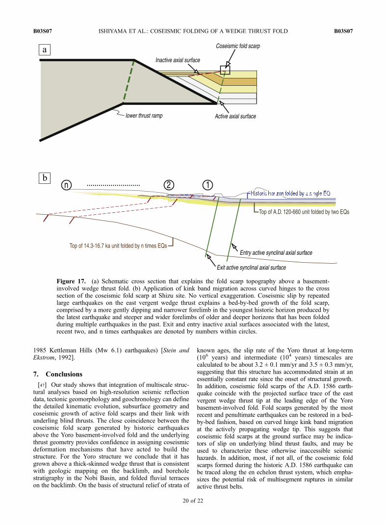
[42] We attribute the uplift events recorded in the foldedhistoric and late Holocene units as evidence for growth ofthe coseismic fold scarp in past earthquakes above thebasement-involved wedge thrust fold (Figure 17). Keyobservations include (1) sedimentary units that thickenacross the scarp and (2) structural relief on a topographicfold scarp that is coincident with the active synclinal axialsurface (above the wedge tip) defined by older strata. Inaddition, the width of strata folded in the forelimb narrowsupward in a growth triangle [Suppe et al., 1992]. The widthof the east dipping forelimb as measured in the youngestfolded deposit (unit 1; floodplain sand and mud) is less than20 m wide at the ground surface, whereas it is 40 m wideacross unit 2 (peat deposits) at 5 m depth, and 100 m wideas measured on late Pleistocene alluvial fan deposits at 40 mdepth. This observation indicates bed-by-bed growth ofcoseismic fold scarps above the basement-involved wedgethrust albeit by numerous earthquakes between datedstratigraphic intervals.
[43] Another key observation is that strata folded at thebase of the forelimb curve gently upward across a broadzone of folding, suggesting that it is not a classic fault bendfold with sharp hinges. Moreover, the 20 m wide forelimbdefined at the ground surface, which we have shown to beproduced by a single event in A.D. 1586, is an unrealisticamount of fault slip for an earthquake of this magnitude.Given a wedge thrust fold solution for the structure, weinterpret the apparently large width of the forelimb at theground surface as evidence for growth by kink bandmigration across a curved synclinal hinge [Suppe et al.,1997], rather than by progressive limb rotation [Riba,1976].
[44] While the easternmost pair of entry and exit activesynclinal axial surfaces extending from the tip of thebasement thrust wedge is ‘‘fixed’’ at the base of thecoseismic fold scarp, corresponding inactive axial surfacesmove up onto the forelimb as coseismic slip is accruedduring repeated blind thrust earthquakes. This model pre-dicts a more gentle dipping and narrower forelimb in theyoungest historic horizon produced by the latest earthquakeand steeper and wider forelimbs of older and deeperhorizons that have been folded during multiple earthquakesin the past (Figure 17).
[45] This kinematic interpretation of the fold scarp pro-vides insight into bed-by-bed growth of the fold limbsrecorded by a fold scarp geomorphology. The fold scarpformed by the growth of the fold limb during the penulti-mate paleoseismic event has been partly removed byerosion due to a change in base level associated with a fallin regional sea level, as suggested by a sinuous east facingterrace riser between the lower and higher Holocene terra-ces, and a buttress unconformity between unit 1 and 2.Subsequent deposition of unit 1 buttressing against theterrace riser was followed by coseismic folding during thelatest paleoseismic event, which formed the frontal scarpthat separates the lower Holocene terrace from modernalluvial plain. This kinematic interpretation of structuralgrowth of the coseismic fold scarp and subsurface stratig-raphy thus indicate that the fold scarp has formed as aconvolution of bed-by-bed coseismic growth of fold limbsand deposition, and/or erosion events between discreteearthquake events.
[46] Perhaps most interestingly, similar coseismic foldscarps are found at the base of the forelimbs of adjacentactive folds in the NIFZ such as Kuwana anticline andYokkaichi anticline (Figure 3). Analysis of folded stratadefined by borehole transects and radiocarbon dating sug-gest that most, if not all, of these scarps, formed during thehistoric A.D. 1586 earthquake [Sugai et al., 1998, 1999a;Togo, 2000; Ishiyama et al., 2002b]. Kuwana anticline,located south of the Yoro structure, has also formed as aneast vergent basement-involved wedge thrust fold. Thisindicates that, in spite of en echelon pattern of these activefolds, they did not rupture independently but transferred slipfrom one ramp to the next (i.e., multisegment rupture)during the historic earthquake in A.D. 1586. The NIFZthus demonstrates the potential for more hazardous, multi-segment ruptures rather than single segment earthquakessuch as 1982–1985 California earthquake sequence (the1981 New Idria (Mw 5.4), 1983 Coalinga (Mw 6.5), and
B03S07 ISHIYAMA ET AL.: COSEISMIC FOLDING OF A WEDGE THRUST FOLD
19 of 22
B03S07
1985 Kettleman Hills (Mw 6.1) earthquakes) [Stein andEkstrom, 1992].
7. Conclusions
[47] Our study shows that integration of multiscale struc-tural analyses based on high-resolution seismic reflectiondata, tectonic geomorphology and geochronology can definethe detailed kinematic evolution, subsurface geometry andcoseismic growth of active fold scarps and their link withunderling blind thrusts. The close coincidence between thecoseismic fold scarp generated by historic earthquakesabove the Yoro basement-involved fold and the underlyingthrust geometry provides confidence in assigning coseismicdeformation mechanisms that have acted to build thestructure. For the Yoro structure we conclude that it hasgrown above a thick-skinned wedge thrust that is consistentwith geologic mapping on the backlimb, and boreholestratigraphy in the Nobi Basin, and folded fluvial terraceson the backlimb. On the basis of structural relief of strata of
known ages, the slip rate of the Yoro thrust at long-term(106 years) and intermediate (104 years) timescales arecalculated to be about 3.2 ± 0.1 mm/yr and 3.5 ± 0.3 mm/yr,suggesting that this structure has accommodated strain at anessentially constant rate since the onset of structural growth.In addition, coseismic fold scarps of the A.D. 1586 earth-quake coincide with the projected surface trace of the eastvergent wedge thrust tip at the leading edge of the Yorobasement-involved fold. Fold scarps generated by the mostrecent and penultimate earthquakes can be restored in a bed-by-bed fashion, based on curved hinge kink band migrationat the actively propagating wedge tip. This suggests thatcoseismic fold scarps at the ground surface may be indica-tors of slip on underlying blind thrust faults, and may beused to characterize these otherwise inaccessible seismichazards. In addition, most, if not all, of the coseismic foldscarps formed during the historic A.D. 1586 earthquake canbe traced along the en echelon thrust system, which empha-sizes the potential risk of multisegment ruptures in similaractive thrust belts.
Figure 17. (a) Schematic cross section that explains the fold scarp topography above a basement-involved wedge thrust fold. (b) Application of kink band migration across curved hinges to the crosssection of the coseismic fold scarp at Shizu site. No vertical exaggeration. Coseismic slip by repeatedlarge earthquakes on the east vergent wedge thrust explains a bed-by-bed growth of the fold scarp,comprised by a more gently dipping and narrower forelimb in the youngest historic horizon produced bythe latest earthquake and steeper and wider forelimbs of older and deeper horizons that has been foldedduring multiple earthquakes in the past. Exit and entry inactive axial surfaces associated with the latest,recent two, and n times earthquakes are denoted by numbers within circles.
B03S07 ISHIYAMA ET AL.: COSEISMIC FOLDING OF A WEDGE THRUST FOLD
20 of 22
B03S07
[48] Acknowledgments. We thank Toshimichi Nakanishi, AtsumasaOkada, Shigeru Toda, Hajime Kato, Tomoo Echigo, Shinsuke Okada,Nobuhisa Matsuta, Hiroyuki Tsutsumi, Nobuhiko Sugito, NobumasaSuzuki, Haruo Kimura, and colleagues at Aichi Educational University,University of Tokyo, and Kyoto University for invaluable assistance withacquisition of seismic data and discussion. Daisaku Kawabata is alsothanked for providing us with a high-resolution shaded relief map. Finally,our thanks go to Associate Editor James F. Dolan, Tom Pratt, and ananonymous reviewer for their constructive reviews, which greatly improvedthe manuscript. Seismic data acquisitions B-B’ and C-C’ were funded byJSPS Grants-in-Aid for Scientific Research 16200050 to A. Okada andIshiyama, and C-C’ was done as a part of Special Project for EarthquakeDisaster Mitigation in Urban Areas funded by Ministry of Education,Culture, Sports, Science and Technology.
ReferencesAllmendinger, R. W. (1998), Inverse and forward numerical modeling of
trishear fault-propagation folds, Tectonics, 17, 640–656.Apotria, T. G., W. T. Suedden, J. H. Spang, and D. V. Wiltschko (1992),
Kinematic models of deformation at an oblique ramp, in Thrust Tectonics,edited by K. R. McClay, pp. 141–151, CRC Press, Boca Raton, Fla.
Atwater, B. F., et al. (2001), Grouted sediment slices show signs of earth-quake shaking, Eos Trans AGU, 82(49), 603.
Awata, Y., and F. Yoshida (1991), Holocene movement of the Kuwana andYokkaichi faults, northwest of Ise Bay, central Japan (in Japanese), ActiveFault Res., 9, 61–68.
Benedetti, L., P. Tapponnier, G. C. P. King, B. Meyer, and I. Manighetti(2000), Growth folding and active thrusting in the Montello region,Veneto, northern Italy, J. Geophys. Res., 105, 739–766.
Benedetti, L. C., P. Tapponnier, Y. Gaudemer, I. Manighetti, and J. Van derWoerd (2003), Geomorphic evidence for an emergent active thrust alongthe edge of the Po Plain: The Broni-Stradella fault, J. Geophys. Res.,108(B5), 2238, doi:10.1029/2001JB001546.
Bennett, E. R., J. H. Youngson, J. A. Jackson, R. J. Norris, G. M. Raisbeck,F. Yiou, and E. Fielding (2005), Growth of South Rough Ridge, CentralOtago, New Zealand: Using in situ cosmogenic isotopes and geomor-phology to study an active, blind reverse fault, J. Geophys. Res., 110,B02404, doi:10.1029/2004JB003184.
Bullard, T. F., and W. R. Lettis (1993), Quaternary fold deformation asso-ciated with blind thrust faulting, Los Angeles basin, California, J. Geo-phys. Res., 98, 8349–8369.
Burbank, D., A. Meigs, and N. Brozovic (1996), Interactions of growingfolds and coeval depositional systems, Basin Res., 8, 199–223.
Champion, J. A., A. Tate, K. J. Mueller, and M. Guccione (2001), Geo-metry, numerical modeling and revised slip rate for the Reelfoot blindthrust and trishear fault-propagation fold, New Madrid seismic zone, Eng.Geol., 62, 31–49.
Committee for Subsurface Structure of the Nobi Basin (2001), Report onsurvey for subsurface structure of the Nobi basin (in Japanese), report,13 pp., Nagoya, Japan.
Dolan, J. F., S. A. Christofferson, and J. H. Shaw (2003), Recognition ofpaleoearthquakes on the Puente Hills blind thrust fault, California,Science, 300, 115–118.
Dominguez, S., J. Avouac, and R. Michel (2003), Horizontal coseismicdeformation of the 1999 Chi-Chi earthquake measured from SPOTsatellite images: Implications for the seismic cycle along the westernfoothills of central Taiwan, J. Geophys. Res., 108(B2), 2083, doi:10.1029/2001JB000951.
Erslev, E. A. (1991), Trishear fault-propagation folding, Geology, 19, 617–620.
Freymueller, J., N. E. King, and P. Segall (1994), The co-seismic slipdistribution of the Landers earthquake, Bull. Seismol. Soc. Am., 84,646–659.
Furusawa, A. (1990), Volcanic ash layers of the Tokai Group and the Amaand Yatomi Formations under the Nobi Plain, and their correlation (inJapanese with English abstract), J. Geol. Soc. Jpn., 96, 883–901.
Glen, J. M., and R. S. Coe (1997), Paleomagnetism and magnetic suscept-ibility of Pleistocene sediments from drill hole OL-92, Owens Lake, CA,in An 800,000–Year Paleoclimatic Record from Core OL-92, OwensLake, Southeast California, edited by G. I. Smith and J. L. Bischoff,Spec. Pap. Geol. Soc. Am., 317, 67–78.
Groshong, R. H. (2006), 3-D Structural Geology, 400 pp., Springer, NewYork.
Harayama, S., M. Miyamura, F. Yoshida, K. Mimura, and F. Kurimoto(1989), Geology of the Gozaishoyama district, with geologic sheet mapat 1:50,000 (in Japanese with English abstract), report, 145 pp., Geol.Surv. of Jpn., Tsukuba.
Hardy, S., and M. Ford (1997), Numerical modeling of trishear fault-propagation folding, Tectonics, 16, 841–854.
Hung, J., and J. Suppe (2002), Subsurface geometry of the Sani-Chelungpufaults and fold scarp formation in the 1999 Chi-Chi Taiwan earthquake,Eos Trans AGU, 83(47), Fall Meet. Suppl., Abstract T61B-1268.
Ikeda, Y., T. Imaizumi, H. Sato, M. Togo, K. Hirakawa, and T. Miyauchi(Eds.) (2002), Atlas of Quaternary Thrust Faults in Japan (in Japanese),254 pp., Univ. Tokyo Press, Tokyo.
Ishiyama, T., K. Takemura, and A. Okada (1999), Structural growth rate ofthe western margin of the Suzuka Range during Quaternary (in Japanesewith English abstract), J. Seismol. Soc. Jpn., 52, 229–240.
Ishiyama, T., K. J. Mueller, M. Togo, K. Takemura, and A. Okada (2002a),Geomorphology and kinematics of the Nobi-Ise active fault zone, centralJapan: Implications for the kinematic growth of tectonic landforms withinan active thrust belt, Eos Trans. AGU, 83(47), Fall Meet. Suppl., AbstractS11B-1140.
Ishiyama, T., M. Togo, T. Imaizumi, H. Sato, T. Nakata, T. Nohara, andT. Haraguchi (2002b), Evolution of fault-related landform associated withlate Holocene faulting on the Yoro fault, revealed by drilling survey atShizu-Shobuhara Site, Nan-no Town, Gifu Prefecture, central Japan(in Japanese with English abstract), Active Fault Res., 22, 115–126.
Ishiyama, T., K. Mueller, M. Togo, A. Okada, and K. Takemura (2004),Geomorphology, kinematic history, and earthquake behavior of the activeKuwana wedge thrust anticline, central Japan, J. Geophys. Res., 109,B12408, doi:10.1029/2003JB002547.
Johnson, K. M., Y. J. Hsu, P. Segall, and S. B. Yu (2001), Fault geometryand slip distribution of the 1999 Chi-Chi, Taiwan earthquake imagedfrom inversion of GPS data, Geophys. Res. Lett., 28, 2285–2288.
Kawabata, D., and T. Ishiyama (2006), Digital photogrametry of lateHolocene fold scarps along the Yoro fault, paper presented at JapanGeoscience Union Meeting, Chiba.
Kelson, K. I., G. D. Simpson, R. B. VanArsdale, C. C. Haraden, and W. R.Lettis (1996), Multiple late Holocene earthquakes along the Reelfoot fault,central New Madrid seismic zone, J. Geophys. Res., 101, 6151–6170.
Kishimoto, K. (2000), Combined bathymetric and topographic mesh data:Japan 250 m. grid, Open File Rep. 353, 1-CD-ROM, Geol. Surv. of Jpn.,Tsukuba.
Lave, J., and J. P. Avouac (2000), Active folding of fluvial terraces acrossthe Siwaliks Hills, Himalayas of central Nepal, J. Geophys. Res., 105,5735–5770.
Lee, J. C., C. Rubin, K. Mueller, Y. G. Chen, Y. C. Chan, K. Sieh, H. T.Chu, and W. S. Chen (2004), Quantitative analysis of movement along anearthquake thrust scarp: A case study of a vertical exposure of the 1999surface rupture of the Chelungpu fault at Wufeng, western Taiwan,J. Asian Earth Sci., 23, 263–273.
Machida, H., and F. Arai (2003), Atlas of Tephra in and Around Japan (inJapanese), 336 pp., Univ. of Tokyo Press, Tokyo.
Medwedeff, D. A. (1992), Geometry and kinematics of an active, laterallypropagating wedge thrust, Wheeler Ridge, California, in StructuralGeology of Fold and Thrust Belts, edited by S. Mitra and G. W. Fisher,pp. 3–28, Johns Hopkins Univ. Press, Baltimore, Md.
Medwedeff, D. A., and J. Suppe (1997), Multibend fault-bend folding,J. Struct. Geol., 19, 279–292.
Miyamura, M., K. Mimura, and T. Yokoyama (1976), Geology of theHikone-Tobu district, with geologic sheet map at 1:50,000 (in Japanesewith English abstract), 49 pp., Geol. Surv. of Jpn., Tsukuba.
Molnar, P., et al. (1994), Quaternary climatic change and the formation ofriver terraces across growing anticline on the north flank of the TienShan, J. Geol., 102, 583–602.
Mueller, K., and J. Suppe (1997), Growth of Wheeler Ridge anticline,California: Geomorphic evidence for fault-bend-folding behavior duringearthquakes, J. Struct. Geol., 19, 383–396.
Mueller, K., J. Champion, M. Guccione, and K. Kelson (1999), Faultslip rates in the modern New Madrid seismic zone, Science, 286,1135–1138.
Nakanishi, T. (2003), Detection of multiple paleoseismic events based onhigh-resolution sedimentological core analysis, thesis for Doctor ofScience, 131 pp., Kyoto Univ., Kyoto, Japan, March.
Nakata, T., and T. Imaizumi (Eds.) (2002), Digital active fault map of Japan(in Japanese), 60 pp., Univ. of Tokyo Press, Tokyo.
Nakata, T., and K. Shimazaki (1997), Geo-slicer as a tool for active faultresearch (in Japanese with English abstract), J. Geogr., 106, 59–69.
Okada, A., and M. Togo (Eds.) (2000), Active Faults in the Kinki Area,Central Japan: Sheet Maps and Inventories, 395 pp., Univ. of TokyoPress, Tokyo.
Philip, H., and M. Meghraoui (1983), Structural analysis and interpretationof the surface deformations of the El Asnam earthquake of October 10,1980, Tectonics, 2, 17–49.
Philip, H., E. Rogozhin, A. Cisternas, J. C. Bousquet, B. Borisov, andA. Karakhanian (1992), The Armenian earthquake of 1988 December 7:Faulting and folding, neotectonics and paleoseismicity, Geophys. J. Int.,110, 141–158.
B03S07 ISHIYAMA ET AL.: COSEISMIC FOLDING OF A WEDGE THRUST FOLD
21 of 22
B03S07
Pratt, T. L., J. H. Shaw, J. F. Dolan, S. A. Christofferson, R. A. Williams,J. K. Odum, and A. Plesch (2002), Shallow seismic imaging of foldsabove the Puente Hills blind-thrust fault, Los Angeles, California, Geo-phys. Res. Lett., 29(9), 1304, doi:10.1029/2001GL014313.
Research Group for Active Faults (1991), Active Faults in Japan: SheetMaps and Inventories (in Japanese), 437 pp., Univ. of Tokyo Press,Tokyo.
Riba, O. (1976), Syntectonic unconformities of Alto Cardener, SpanishPyrenees–genetic interpretation, Sediment. Geol., 15, 213–233.
Rockwell, T. K., E. A. Keller, M. N. Clark, and D. L. Johnson (1984),Chronology and rates of faulting of Ventura River terraces, California,Geol. Soc. Am. Bull., 95, 1466–1474.
Rockwell, T. K., E. A. Keller, and G. R. Dembroff (1988), Quaternary rateof folding of the Ventura Avenue anticline, western Transverse Ranges,southern California, Geol. Soc. Am. Bull., 100, 850–858.
Sakamoto, T., Y. Takada, T. Kuwabara, and J. Itoigawa (1986), Geology ofthe Nagoya-Nambu district, with geologic sheet map at 1:50,000(in Japanese with English abstract), 55 pp., Geol. Surv. of Jpn., Tsukuba.
Sato, H., et al. (1997), Evolution of the active Senya thrust fault, northernHonshu, Japan. Abstracts 1997, 185, Seismol. Soc. of Jpn., Tokyo.
Scharer, K. M., D. Burbank, J. Chen, and R. Weldon (2006), Kinematicmodels of fluvial terraces over active detachment folds: Constraints onthe growth mechanism of the Kashi-Atushi fold system, Chinese TianShan, Geol. Soc. Am. Bull., 118, 1006–1021.
Shaw, J., and J. Suppe (1994), Active faulting and growth folding in theeastern Santa Barbara Channel, California, Geol. Soc. Am. Bull., 106,607–626.
Shaw, J. H., and J. Suppe (1996), Earthquake hazards of active blind-thrustfaults under the central Los Angeles basin, California, J. Geophys. Res.,101, 8623–8642.
Shaw, J. H., A. Plesch, J. F. Dolan, T. L. Pratt, and P. Fiore (2002), PuenteHills blind-thrust system, Los Angeles, California, Bull. Seismol. Soc.Am., 92, 2946–2960.
Shaw, J. H., C. Connors, and J. Suppe (Eds.) (2005), Seismic interpretationof contractional fault-related folds, AAPG Stud. Geol., 53, 157 pp.
Shyu, J. B. H., K. Sieh, J.-P. Avouac, W.-S. Chen, and Y.-G. Chen (2006),Millennial slip rate of the Longitudinal Valley fault from river terraces:Implications for convergence across the active suture of eastern Taiwan,J. Geophys. Res., 111, B08403, doi:10.1029/2005JB003971.
Stein, R. S., and G. Ekstrom (1992), Seismicity and geometry of a 110-km-long blind thrust fault: 2. Synthesis of the 1982–1985 California earth-quake sequence, J. Geophys. Res., 97, 4865–4883.
Stuiver, M., and P. J. Reimer (1993), Extended 14C database and revisedCALIB radiocarbon calibration program, Radiocarbon, 35, 215–230.
Sugai, T., Y. Awata, and K. Shimokawa (1998), Paleoseismological study ofthe Kuwana fault and the Yokkaichi fault in Mie Prefecture, central Japan(in Japanese with English abstract), Interim Rep. EQ/98/1, pp. 75–90,Geol. Surv. of Jpn., Tsukuba.
Sugai, T., Y. Fusejima, Y. Awata, T. Azuma, Y. Kariya, and Y. Suzuki(1999a), Late Holocene paleoseismicity of the Yoro fault system, centralJapan (in Japanese with English abstract), Interim Rep. EQ/99/3, pp. 89–102, Geol. Surv. of Jpn., Tsukuba.
Sugai, T., Y. Sugiyama, and K. Mizuno (1999b), 900,000–year cyclostrati-graphic record from a 600 m core, GS-NB-1, the Nobi basin, centralJapan (in Japanese with English abstract), Interim Rep. EQ/99/3,pp. 69–76, Geol. Surv. of Jpn., Tsukuba.
Suppe, J. (1983), Geometry and kinematics of fault-bend folding, Am. J.Sci., 283, 684–721.
Suppe, J., and D. Medwedeff (1990), Geometry and kinematics of fault-propagation folding, Ecologae Geol. Helv., 83, 409–454.
Suppe, J., G. T. Chou, and S. C. Hook (1992), Rates of folding and faultingdetermined from growth strata, in Thrust Tectonics, edited by K. R.McClay, pp. 105–121, CRC Press, Boca Raton, Fla.
Suppe, J., F. Sabat, J. A. Munoz, J. Poblet, E. Roca, and J. Verges (1997),Bed-by-bed fold growth by kink-band migration: Sant Llorenc deMorunys, eastern Pyrenees, J. Struct. Geol., 19, 443–461.
Suppe, J., Y. H. Lee, Y. G. Chen, and J. H. Hung (2000), Coseismic fault-bend folding: Fold scarp formation in the 1999 Chi-Chi earthquake(M 7.6), Taiwan fold-and-thrust belt, Eos Trans. AGU, 81(48), 874.
Takada, Y., Y. Kondo, and M. Miyamura (1979), Geology of the Tsushimadistrict, with geologic sheet map at 1:50,000 (in Japanese with Englishabstract), 56 pp., Geol. Surv. of Jpn., Tsukuba.
Takemura, K. (1985), The Plio-Pleistocene Tokai Group and the tectonicdevelopment around Ise Bay of central Japan since Pliocene, Mem. Fac.Sci. Kyoto Univ. Ser. Geol. Mineral., 51, 21–96.
Thompson, S. C., R. J. Weldon, C. M. Rubin, K. Abdrakhmatov, P. Molnar,and G. W. Berger (2002), Late Quaternary slip rates across the centralTien Shan, Kyrgyzstan, central Asia, J. Geophys. Res., 107(B9), 2203,doi:10.1029/2001JB000596.
Togo, M. (2000), Geomorphological Analysis on Surface Ruptures byReverse Faulting in Japan (Bisyo-chikei-niyoru-katsudansou-handoku)(in Japanese), 206 pp., Kokon, Tokyo.
Umitsu, M. (1994), Late Quaternary Environment and Landform Evolutionof Riverine Coastal Lowlands (in Japanese), 270 pp., Kokon, Tokyo.
Usami, T. (2003), Materials for Comprehensive List of Destructive Earth-quakes in Japan, 416–2001 (in Japanese), 603 pp., Univ. of Tokyo Press,Tokyo.
Wei, D., and T. Seno (1998), Determination of the Amurian platemotion, in Mantle Dynamics and Plate Interactions in East Asia,Geodyn. Ser., vol. 27, edited by M. F. J. Flower et al., pp. 337–346,AGU, Washington, D. C.
Yeats, R. S., K. Sieh, and C. R. Allen (1997), The Geology of Earthquakes,568 pp., Oxford Univ. Press, New York.
Yilmaz, O. (1987), Seismic Data Processing, 526 pp., Soc. of Explor.Geophys., Tulsa, Okla.
Yoshida, F. (1984), Geology of the Yokkaichi district, with geologic sheetmap at 1:50,000 (in Japanese with English abstract), 81 pp., Geol. Surv.of Jpn., Tsukuba.
Yoshida, F. (1988), Plio-Pleistocene Tokai Group between the Suzuka andYoro Mountains, central Japan (in Japanese with English abstract),J. Earth Sci., 42, 1–16.
Yoshida, F., C. Kurimoto, and M. Miyamura (1991), Geology of theKuwana district, with geologic sheet map at 1:50,000 (in Japanese withEnglish abstract), 154 pp., Geol. Surv. of Jpn., Tsukuba.
T. Ishiyama, Active Fault Research Center, Geological Survey of Japan,National Institute of Advanced Industrial Science and Technology, Site 7,1-1-1 Higashi, Tsukuba, Ibaraki 305-8567, Japan. ([email protected])
K. Mueller, Department of Geological Sciences, University of Colorado,Boulder, CO 80309-0399, USA. ([email protected])
H. Sato, Earthquake Research Institute, University of Tokyo, 1-1-1,Yayoi, Bunkyo-ku, Tokyo 113-0032, Japan. ([email protected])
M. Togo, Department of Geoscience, Hosei University, Aihara-Cho,4342, Machida 194-0298, Japan. ([email protected])
B03S07 ISHIYAMA ET AL.: COSEISMIC FOLDING OF A WEDGE THRUST FOLD
22 of 22
B03S07