crx-vf manual v1.0 - fullerton group – university of...
TRANSCRIPT

| www.lakeshore.com
User’s Manual
CRX-VFProbe Station
Lake Shore Cryotronics, Inc.575 McCorkle Blvd.
Westerville, Ohio 43082-8888 USA
[email protected]@lakeshore.com
www.lakeshore.com
Fax: (614) 891-1392Telephone: (614) 891-2243
Methods and apparatus disclosed and described herein have been developed solely on company funds of Lake Shore Cryotronics, Inc. No government or other contractual support or relationship whatsoever has existed which in any way affects or mitigates proprietary rights of Lake Shore Cryotronics, Inc. in these developments. Methods and apparatus disclosed herein may be subject to U.S. Patents existing or applied for. Lake Shore Cryotronics, Inc. reserves the right to add, improve, modify, or withdraw functions, design modifications, or products at any time without notice. Lake Shore shall not be liable for errors contained herein or for incidental or consequential damages in connection with furnishing, performance, or use of this material.
Rev. 1.0 P/N 119-513 26 October 2012

Model CRX-VF Probe Station
LIMITED WARRANTY STATEMENTWARRANTY PERIOD: THREE (3) YEARS1.Lake Shore warrants that products manufactured by Lake Shore (the "Product") will be free from defects in materials and workmanship for three years from the date of Purchaser's physical receipt of the Prod-uct (the "Warranty Period"). If Lake Shore receives notice of any such defects during the Warranty Period and the defective Product is shipped freight prepaid back to Lake Shore, Lake Shore will, at its option, either repair or replace the Product (if it is so defective) with-out charge for parts, service labor or associated customary return shipping cost to the Purchaser. Replacement for the Product may be by either new or equivalent in performance to new. Replacement or repaired parts, or a replaced Product, will be warranted for only the unexpired portion of the original warranty or 90 days (whichever is greater).
2.Lake Shore warrants the Product only if the Product has been sold by an authorized Lake Shore employee, sales representative, dealer or an authorized Lake Shore original equipment manufacturer (OEM).
3.The Product may contain remanufactured parts equivalent to new in performance or may have been subject to incidental use when it is originally sold to the Purchaser.
4.The Warranty Period begins on the date of Purchaser's physical receipt of the Product or later on the date of operational training and verification (OT&V) of the Product if the service is performed by Lake Shore, provided that if the Purchaser schedules or delays the Lake Shore OT&V for more than 30 days after delivery then the Warranty Period begins on the 31st day after Purchaser's physical receipt of the Product.
5.This limited warranty does not apply to defects in the Product resulting from (a) improper or inadequate installation (unless OT&V services are performed by Lake Shore), maintenance, repair or cali-bration, (b) fuses, software, power surges, lightning and non-rechargeable batteries, (c) software, interfacing, parts or other sup-plies not furnished by Lake Shore, (d) unauthorized modification or misuse, (e) operation outside of the published specifications, (f) improper site preparation or site maintenance (g) natural disasters such as flood, fire, wind, or earthquake, or (h) damage during ship-ment other than original shipment to you if shipped through a Lake Shore carrier.
6.This limited warranty does not cover: (a) regularly scheduled or ordi-nary and expected recalibrations of the Product; (b) accessories to the Product (such as probe tips and cables, holders, wire, grease, varnish, feed throughs, etc.); (c) consumables used in conjunction with the Product (such as probe tips and cables, probe holders, sample tails, rods and holders, ceramic putty for mounting samples, Hall sample cards, Hall sample enclosures, etc.); or, (d) non-Lake Shore branded Products that are integrated with the Product.
7. To the extent allowed by applicable law,, this limited warranty is the only warranty applicable to the Product and replaces all other war-ranties or conditions, express or implied, including, but not limited to, the implied warranties or conditions of merchantability and fitness for a particular purpose. Specifically, except as provided herein,
LakeShore undertakes no responsibility that the products will be fit for any particular purpose for which you may be buying the Products. Any implied warranty is limited in duration to the warranty period. No oral or written information, or advice given by the Company, its Agents or Employees, shall create a warranty or in any way increase the scope of this limited warranty. Some countries, states or provinces do not allow limitations on an implied warranty, so the above limita-tion or exclusion might not apply to you. This warranty gives you spe-cific legal rights and you might also have other rights that vary from country to country, state to state or province to province.
8.Further, with regard to the United Nations Convention for Interna-tional Sale of Goods (CISC,) if CISG is found to apply in relation to this agreement, which is specifically disclaimed by Lake Shore, then this limited warranty excludes warranties that: (a) the Product is fit for the purpose for which goods of the same description would ordinarily be used, (b) the Product is fit for any particular purpose expressly or impliedly made known to Lake Shore at the time of the conclusion of the contract. (c) the Product is contained or packaged in a manner usual for such goods or in a manner adequate to preserve and protect such goods where it is shipped by someone other than a carrier hired by Lake Shore.
9. Lake Shore disclaims any warranties of technological value or of non-infringement with respect to the Product and Lake Shore shall have no duty to defend, indemnify, or hold harmless you from and against any or all damages or costs incurred by you arising from the infringement of patents or trademarks or violation or copyrights by the Product.
10.THIS WARRANTY IS NOT TRANSFERRABLE. This warranty is not transferrable.
11.Except to the extent prohibited by applicable law, neither Lake Shore nor any of its subsidiaries, affiliates or suppliers will be held lia-ble for direct, special, incidental, consequential or other damages (including lost profit, lost data, or downtime costs) arising out of the use, inability to use or result of use of the product, whether based in warranty, contract, tort or other legal theory, regardless whether or not Lake Shore has been advised of the possibility of such damages. Purchaser's use of the Product is entirely at Purchaser's risk. Some countries, states and provinces do not allow the exclusion of liability for incidental or consequential damages, so the above limitation may not apply to you.
12.This limited warranty gives you specific legal rights, and you may also have other rights that vary within or between jurisdictions where the product is purchased and/or used. Some jurisdictions do not allow limitation in certain warranties, and so the above limitations or exclu-sions of some warranties stated above may not apply to you.
13.Except to the extent allowed by applicable law, the terms of this limited warranty statement do not exclude, restrict or modify the mandatory statutory rights applicable to the sale of the product to you.

CERTIFICATIONLake Shore certifies that this product has been inspected and tested in accordance with its published specifications and that this product met its published specifications at the time of shipment. The accu-racy and calibration of this product at the time of shipment are trace-able to the United States National Institute of Standards and Technology (NIST); formerly known as the National Bureau of Stan-dards (NBS).
TRADEMARK ACKNOWLEDGMENTMany manufacturers and sellers claim designations used to distin-guish their products as trademarks. Where those designations appear in this manual and Lake Shore was aware of a trademark claim, they appear with initial capital letters and the ™ or ® symbol.Apiezon® is a registered trademark of M&I Materials, Ltd.Parker’s® Perfect is a is a registered trademark of Edmund Optics®.Kimwipes® is a registered trademark of Kimberly-Clark Worldwide.Stycast® is a registered trademark of Emerson & Cuming.Swagelok® is a registered trademark of Crawford Fitting Company Corporation.Tarn-X® is a registered trademark of Jelmar, Inc.Teflon® and Kapton® are trademarks of DuPont De Nemours.
Copyright 2012 Lake Shore Cryotronics, Inc. All rights reserved. No portion of this manual may be reproduced, stored in a retrieval system, or transmitted, in any form or by any means, electronic, mechanical, photocopying, recording, or otherwise, without the express written permission of Lake Shore.
| www.lakeshore.com

Model CRX-VF Probe Station
i
Table of Contents
Chapter 1 Introduction
1.1 General . . . . . . . . . . . . . . . . . . . . . . . . . . . . . . . . . . . . . . . . . . . . . . . . . . . . . . . . . . . . . . . . . . . . . . . . . . . . . . . . 11.2 Product Description . . . . . . . . . . . . . . . . . . . . . . . . . . . . . . . . . . . . . . . . . . . . . . . . . . . . . . . . . . . . . . . . . . . 1
1.2.1 Applications . . . . . . . . . . . . . . . . . . . . . . . . . . . . . . . . . . . . . . . . . . . . . . . . . . . . . . . . . . . . . . . . . . . . . 21.2.2 Materials . . . . . . . . . . . . . . . . . . . . . . . . . . . . . . . . . . . . . . . . . . . . . . . . . . . . . . . . . . . . . . . . . . . . . . . . 2
1.3 Specifications . . . . . . . . . . . . . . . . . . . . . . . . . . . . . . . . . . . . . . . . . . . . . . . . . . . . . . . . . . . . . . . . . . . . . . . . . 21.3.1 Magnetic Field . . . . . . . . . . . . . . . . . . . . . . . . . . . . . . . . . . . . . . . . . . . . . . . . . . . . . . . . . . . . . . . . . . 21.3.2 Temperature* . . . . . . . . . . . . . . . . . . . . . . . . . . . . . . . . . . . . . . . . . . . . . . . . . . . . . . . . . . . . . . . . . . . 31.3.3 CCR Vibration . . . . . . . . . . . . . . . . . . . . . . . . . . . . . . . . . . . . . . . . . . . . . . . . . . . . . . . . . . . . . . . . . . . 31.3.4 Pump Down Time . . . . . . . . . . . . . . . . . . . . . . . . . . . . . . . . . . . . . . . . . . . . . . . . . . . . . . . . . . . . . . . 31.3.5 Vacuum . . . . . . . . . . . . . . . . . . . . . . . . . . . . . . . . . . . . . . . . . . . . . . . . . . . . . . . . . . . . . . . . . . . . . . . . . 31.3.6 Probe Arms . . . . . . . . . . . . . . . . . . . . . . . . . . . . . . . . . . . . . . . . . . . . . . . . . . . . . . . . . . . . . . . . . . . . . . 31.3.7 Sample Space . . . . . . . . . . . . . . . . . . . . . . . . . . . . . . . . . . . . . . . . . . . . . . . . . . . . . . . . . . . . . . . . . . . 31.3.8 CCR Compressor Requirements . . . . . . . . . . . . . . . . . . . . . . . . . . . . . . . . . . . . . . . . . . . . . . . . 41.3.9 Frequency Range . . . . . . . . . . . . . . . . . . . . . . . . . . . . . . . . . . . . . . . . . . . . . . . . . . . . . . . . . . . . . . . . 41.3.10 Optical . . . . . . . . . . . . . . . . . . . . . . . . . . . . . . . . . . . . . . . . . . . . . . . . . . . . . . . . . . . . . . . . . . . . . . . . . 41.3.11 Sample Holder . . . . . . . . . . . . . . . . . . . . . . . . . . . . . . . . . . . . . . . . . . . . . . . . . . . . . . . . . . . . . . . . . 4
1.4 Standard Equipment . . . . . . . . . . . . . . . . . . . . . . . . . . . . . . . . . . . . . . . . . . . . . . . . . . . . . . . . . . . . . . . . . . 51.5 Required User Configurable Equipment . . . . . . . . . . . . . . . . . . . . . . . . . . . . . . . . . . . . . . . . . . . . . . 6
1.5.1 Up to Six XYZ Precision Micro-manipulated Stages . . . . . . . . . . . . . . . . . . . . . . . . . . . . 61.5.2 ZN50 DC/RF Probes . . . . . . . . . . . . . . . . . . . . . . . . . . . . . . . . . . . . . . . . . . . . . . . . . . . . . . . . . . . . . 61.5.3 ZN50 DC/RF Cables . . . . . . . . . . . . . . . . . . . . . . . . . . . . . . . . . . . . . . . . . . . . . . . . . . . . . . . . . . . . . 71.5.4 GSG Microwave Probes . . . . . . . . . . . . . . . . . . . . . . . . . . . . . . . . . . . . . . . . . . . . . . . . . . . . . . . . . 71.5.5 GSG Microwave Cables . . . . . . . . . . . . . . . . . . . . . . . . . . . . . . . . . . . . . . . . . . . . . . . . . . . . . . . . . 71.5.6 Sample Holders . . . . . . . . . . . . . . . . . . . . . . . . . . . . . . . . . . . . . . . . . . . . . . . . . . . . . . . . . . . . . . . . . 8
1.6 Equipment Options . . . . . . . . . . . . . . . . . . . . . . . . . . . . . . . . . . . . . . . . . . . . . . . . . . . . . . . . . . . . . . . . . . . 91.7 Safety Considerations . . . . . . . . . . . . . . . . . . . . . . . . . . . . . . . . . . . . . . . . . . . . . . . . . . . . . . . . . . . . . . . . . 9
Chapter 2 System Overview
2.1 General . . . . . . . . . . . . . . . . . . . . . . . . . . . . . . . . . . . . . . . . . . . . . . . . . . . . . . . . . . . . . . . . . . . . . . . . . . . . . . . 112.2 Major Components . . . . . . . . . . . . . . . . . . . . . . . . . . . . . . . . . . . . . . . . . . . . . . . . . . . . . . . . . . . . . . . . . . 11
2.2.1 Probe Station . . . . . . . . . . . . . . . . . . . . . . . . . . . . . . . . . . . . . . . . . . . . . . . . . . . . . . . . . . . . . . . . . . . 122.2.1.1 Vacuum Chamber and CCR Vacuum Shroud . . . . . . . . . . . . . . . . . . . . . . . . . 132.2.1.2 Sample Cooling Assembly . . . . . . . . . . . . . . . . . . . . . . . . . . . . . . . . . . . . . . . . . . . . . 142.2.1.3 Closed Cycle Refrigerator(CCR) . . . . . . . . . . . . . . . . . . . . . . . . . . . . . . . . . . . . . . . . 152.2.1.4 Superconducting Magnet . . . . . . . . . . . . . . . . . . . . . . . . . . . . . . . . . . . . . . . . . . . . . 162.2.1.5 Micro-manipulated Stages . . . . . . . . . . . . . . . . . . . . . . . . . . . . . . . . . . . . . . . . . . . . 17
2.2.2 Instrument Console . . . . . . . . . . . . . . . . . . . . . . . . . . . . . . . . . . . . . . . . . . . . . . . . . . . . . . . . . . . 182.2.2.1 Temperature Instrumentation . . . . . . . . . . . . . . . . . . . . . . . . . . . . . . . . . . . . . . . . 192.2.2.2 Magnet Power Supply . . . . . . . . . . . . . . . . . . . . . . . . . . . . . . . . . . . . . . . . . . . . . . . . . 20
2.2.3 Pressurized Gas System . . . . . . . . . . . . . . . . . . . . . . . . . . . . . . . . . . . . . . . . . . . . . . . . . . . . . . . . 212.2.4 Vision System . . . . . . . . . . . . . . . . . . . . . . . . . . . . . . . . . . . . . . . . . . . . . . . . . . . . . . . . . . . . . . . . . . 222.2.5 Turbo Pumping System (Optional TPS FRG or Equivalent) . . . . . . . . . . . . . . . . . . . . 22
2.3 Configurations, Options and Accessories . . . . . . . . . . . . . . . . . . . . . . . . . . . . . . . . . . . . . . . . . . . . 232.3.1 Probing Configurations . . . . . . . . . . . . . . . . . . . . . . . . . . . . . . . . . . . . . . . . . . . . . . . . . . . . . . . . 232.3.2 DC/RF (ZN50) Probe Configurations . . . . . . . . . . . . . . . . . . . . . . . . . . . . . . . . . . . . . . . . . . . 23
2.3.2.1 ZN50 Probes . . . . . . . . . . . . . . . . . . . . . . . . . . . . . . . . . . . . . . . . . . . . . . . . . . . . . . . . . . . 232.3.2.2 ZN50 Compatible Probe Cables and Connectors . . . . . . . . . . . . . . . . . . . . . 242.3.2.3 ZN50-Compatible Probe Mount . . . . . . . . . . . . . . . . . . . . . . . . . . . . . . . . . . . . . . 25
2.3.3 Microwave Probe Configurations . . . . . . . . . . . . . . . . . . . . . . . . . . . . . . . . . . . . . . . . . . . . . 252.3.3.1 Microwave-Compatible Probes . . . . . . . . . . . . . . . . . . . . . . . . . . . . . . . . . . . . . . . 252.3.3.2 Microwave-Compatible Cables and Connectors . . . . . . . . . . . . . . . . . . . . . . 262.3.3.3 Microwave Calibration Substrate . . . . . . . . . . . . . . . . . . . . . . . . . . . . . . . . . . . . . 26
| www.lakeshore.com
ii TABLE OF CONTENTS
2.3.4 Optical Fiber Assembly . . . . . . . . . . . . . . . . . . . . . . . . . . . . . . . . . . . . . . . . . . . . . . . . . . . . . . . . 272.3.5 Sample Holders . . . . . . . . . . . . . . . . . . . . . . . . . . . . . . . . . . . . . . . . . . . . . . . . . . . . . . . . . . . . . . . . 27
2.3.5.1 Grounded Sample Holders . . . . . . . . . . . . . . . . . . . . . . . . . . . . . . . . . . . . . . . . . . . . 272.3.5.2 Isolated Sample Holders . . . . . . . . . . . . . . . . . . . . . . . . . . . . . . . . . . . . . . . . . . . . . . . 272.3.5.3 Coaxial Sample Holders . . . . . . . . . . . . . . . . . . . . . . . . . . . . . . . . . . . . . . . . . . . . . . . 282.3.5.4 Triaxial Sample Holder . . . . . . . . . . . . . . . . . . . . . . . . . . . . . . . . . . . . . . . . . . . . . . . . 28
2.3.6 Vision System Configuration . . . . . . . . . . . . . . . . . . . . . . . . . . . . . . . . . . . . . . . . . . . . . . . . . . 282.3.6.1 Microscopes . . . . . . . . . . . . . . . . . . . . . . . . . . . . . . . . . . . . . . . . . . . . . . . . . . . . . . . . . . . 282.3.6.2 Lighting Types . . . . . . . . . . . . . . . . . . . . . . . . . . . . . . . . . . . . . . . . . . . . . . . . . . . . . . . . . 29
2.3.7 Turbo Pumping System (TPS FRG)and Pumping Kit (PS-PKIT) . . . . . . . . . . . . . . . . 302.3.8 Pump Line Vibration Isolator (PS-PLVI-40) . . . . . . . . . . . . . . . . . . . . . . . . . . . . . . . . . . . 312.3.9 High Vacuum Option (PS-HV-CPX) . . . . . . . . . . . . . . . . . . . . . . . . . . . . . . . . . . . . . . . . . . . . 312.3.10 Recirculating Chiller Option (RC-EM10) . . . . . . . . . . . . . . . . . . . . . . . . . . . . . . . . . . . . . 31
2.4 Considerations for DC/RF Electrical Measurements. . . . . . . . . . . . . . . . . . . . . . . . . . . . . . . . . 312.4.1 Grounding, Shielding, and Isolation for DC/RF Measurements . . . . . . . . . . . . . . . 31
2.4.1.1 Ground Reference . . . . . . . . . . . . . . . . . . . . . . . . . . . . . . . . . . . . . . . . . . . . . . . . . . . . . 312.4.1.2 Avoiding Ground Loops . . . . . . . . . . . . . . . . . . . . . . . . . . . . . . . . . . . . . . . . . . . . . . . . 322.4.1.3 Shielding . . . . . . . . . . . . . . . . . . . . . . . . . . . . . . . . . . . . . . . . . . . . . . . . . . . . . . . . . . . . . . . 332.4.1.4 Noise Isolation . . . . . . . . . . . . . . . . . . . . . . . . . . . . . . . . . . . . . . . . . . . . . . . . . . . . . . . . . 33
2.4.2 Basic DC Electrical Measurements . . . . . . . . . . . . . . . . . . . . . . . . . . . . . . . . . . . . . . . . . . . . 342.4.3 Basic RF Electrical Measurements . . . . . . . . . . . . . . . . . . . . . . . . . . . . . . . . . . . . . . . . . . . . 342.4.4 Conductive Back Side Features . . . . . . . . . . . . . . . . . . . . . . . . . . . . . . . . . . . . . . . . . . . . . . . . 352.4.5 Back Side Voltage Biasing . . . . . . . . . . . . . . . . . . . . . . . . . . . . . . . . . . . . . . . . . . . . . . . . . . . . . . 352.4.6 Small Signal/Low Noise DC/RF Measurements . . . . . . . . . . . . . . . . . . . . . . . . . . . . . . . 36
2.4.6.1 Noise Isolation for Low Noise Measurements . . . . . . . . . . . . . . . . . . . . . . . . 362.4.6.2 Sample Isolation for Low Noise Measurements . . . . . . . . . . . . . . . . . . . . . . 372.4.6.3 Additional Considerations for Low Noise Measurements. . . . . . . . . . . . . 37
2.4.7 Measuring Low Resistance . . . . . . . . . . . . . . . . . . . . . . . . . . . . . . . . . . . . . . . . . . . . . . . . . . . . 372.4.8 High Impedance/Low Leakage Measurements . . . . . . . . . . . . . . . . . . . . . . . . . . . . . . . 37
2.4.8.1 Grounding and Shielding . . . . . . . . . . . . . . . . . . . . . . . . . . . . . . . . . . . . . . . . . . . . . . 382.4.8.2 Driven Guards . . . . . . . . . . . . . . . . . . . . . . . . . . . . . . . . . . . . . . . . . . . . . . . . . . . . . . . . . . 382.4.8.3 Guarded Probe Station Configurations . . . . . . . . . . . . . . . . . . . . . . . . . . . . . . . 382.4.8.4 Measurement Voltage Limits . . . . . . . . . . . . . . . . . . . . . . . . . . . . . . . . . . . . . . . . . . 40
2.5 Considerations for Microwave Measurements . . . . . . . . . . . . . . . . . . . . . . . . . . . . . . . . . . . . . 402.5.1 Microwave Cables and Connectors . . . . . . . . . . . . . . . . . . . . . . . . . . . . . . . . . . . . . . . . . . . 402.5.2 Ground Return Path . . . . . . . . . . . . . . . . . . . . . . . . . . . . . . . . . . . . . . . . . . . . . . . . . . . . . . . . . . . 422.5.3 Pad Construction and Impedance Matching . . . . . . . . . . . . . . . . . . . . . . . . . . . . . . . . . . 42
2.5.3.1 Probe Crosstalk . . . . . . . . . . . . . . . . . . . . . . . . . . . . . . . . . . . . . . . . . . . . . . . . . . . . . . . . 422.5.4 Calibration with the CS-5 Calibration Standard . . . . . . . . . . . . . . . . . . . . . . . . . . . . . . 432.5.5 Temperature Effects of Calibration . . . . . . . . . . . . . . . . . . . . . . . . . . . . . . . . . . . . . . . . . . . . 442.5.6 Planarization . . . . . . . . . . . . . . . . . . . . . . . . . . . . . . . . . . . . . . . . . . . . . . . . . . . . . . . . . . . . . . . . . . 45
2.6 Contact Quality . . . . . . . . . . . . . . . . . . . . . . . . . . . . . . . . . . . . . . . . . . . . . . . . . . . . . . . . . . . . . . . . . . . . . . 452.6.1 Contact Material . . . . . . . . . . . . . . . . . . . . . . . . . . . . . . . . . . . . . . . . . . . . . . . . . . . . . . . . . . . . . . . 452.6.2 Contact Area. . . . . . . . . . . . . . . . . . . . . . . . . . . . . . . . . . . . . . . . . . . . . . . . . . . . . . . . . . . . . . . . . . . . 452.6.3 Oxidation . . . . . . . . . . . . . . . . . . . . . . . . . . . . . . . . . . . . . . . . . . . . . . . . . . . . . . . . . . . . . . . . . . . . . . 462.6.4 Four-Lead Measurement . . . . . . . . . . . . . . . . . . . . . . . . . . . . . . . . . . . . . . . . . . . . . . . . . . . . . . 462.6.5 Ohmic versus Non-ohmic Contacts . . . . . . . . . . . . . . . . . . . . . . . . . . . . . . . . . . . . . . . . . . . 462.6.6 Measuring Contact Quality . . . . . . . . . . . . . . . . . . . . . . . . . . . . . . . . . . . . . . . . . . . . . . . . . . . . 462.6.7 Lab Protocol . . . . . . . . . . . . . . . . . . . . . . . . . . . . . . . . . . . . . . . . . . . . . . . . . . . . . . . . . . . . . . . . . . . . 46
Chapter 3 Installation and Setup
3.1 General . . . . . . . . . . . . . . . . . . . . . . . . . . . . . . . . . . . . . . . . . . . . . . . . . . . . . . . . . . . . . . . . . . . . . . . . . . . . . . . 473.1.1 Lake Shore Assisted Installation . . . . . . . . . . . . . . . . . . . . . . . . . . . . . . . . . . . . . . . . . . . . . . . 47
3.2 Site Requirements . . . . . . . . . . . . . . . . . . . . . . . . . . . . . . . . . . . . . . . . . . . . . . . . . . . . . . . . . . . . . . . . . . . 473.2.1 Space Requirements and Suggested Layout . . . . . . . . . . . . . . . . . . . . . . . . . . . . . . . . . . 473.2.2 Environmental Requirements and Concerns . . . . . . . . . . . . . . . . . . . . . . . . . . . . . . . . . 49
3.2.2.1 Vibration . . . . . . . . . . . . . . . . . . . . . . . . . . . . . . . . . . . . . . . . . . . . . . . . . . . . . . . . . . . . . . 49
Model CRX-VF Probe Station

iii
3.2.2.2 Electrical Noise . . . . . . . . . . . . . . . . . . . . . . . . . . . . . . . . . . . . . . . . . . . . . . . . . . . . . . . . 493.2.2.3 Ventilation . . . . . . . . . . . . . . . . . . . . . . . . . . . . . . . . . . . . . . . . . . . . . . . . . . . . . . . . . . . . . 493.2.2.4 Magnetic Fields . . . . . . . . . . . . . . . . . . . . . . . . . . . . . . . . . . . . . . . . . . . . . . . . . . . . . . . 493.2.2.5 Safety Compliance . . . . . . . . . . . . . . . . . . . . . . . . . . . . . . . . . . . . . . . . . . . . . . . . . . . . 50
3.2.3 Power Requirements . . . . . . . . . . . . . . . . . . . . . . . . . . . . . . . . . . . . . . . . . . . . . . . . . . . . . . . . . . . 503.2.4 Water Requirements . . . . . . . . . . . . . . . . . . . . . . . . . . . . . . . . . . . . . . . . . . . . . . . . . . . . . . . . . . . 51
3.2.4.1 Water Flow and Temperature . . . . . . . . . . . . . . . . . . . . . . . . . . . . . . . . . . . . . . . . . 513.2.4.2 Water Quality . . . . . . . . . . . . . . . . . . . . . . . . . . . . . . . . . . . . . . . . . . . . . . . . . . . . . . . . . 513.2.4.3 Water Routing and Connections . . . . . . . . . . . . . . . . . . . . . . . . . . . . . . . . . . . . . . 52
3.2.5 Vacuum Requirements . . . . . . . . . . . . . . . . . . . . . . . . . . . . . . . . . . . . . . . . . . . . . . . . . . . . . . . . 523.2.6 Gas Requirements . . . . . . . . . . . . . . . . . . . . . . . . . . . . . . . . . . . . . . . . . . . . . . . . . . . . . . . . . . . . . 52
3.3 Unpacking the Probe Station . . . . . . . . . . . . . . . . . . . . . . . . . . . . . . . . . . . . . . . . . . . . . . . . . . . . . . . . 533.3.1 Shipping Containers . . . . . . . . . . . . . . . . . . . . . . . . . . . . . . . . . . . . . . . . . . . . . . . . . . . . . . . . . . . 533.3.2 Inspecting for Shipping Damage . . . . . . . . . . . . . . . . . . . . . . . . . . . . . . . . . . . . . . . . . . . . . . 533.3.3 Required Tools . . . . . . . . . . . . . . . . . . . . . . . . . . . . . . . . . . . . . . . . . . . . . . . . . . . . . . . . . . . . . . . . . 543.3.4 Moving and Lifting the Probe Station . . . . . . . . . . . . . . . . . . . . . . . . . . . . . . . . . . . . . . . . . 543.3.5 Uncrating the Probe Station . . . . . . . . . . . . . . . . . . . . . . . . . . . . . . . . . . . . . . . . . . . . . . . . . . . 553.3.6 Uncrating the Instrument Console and Accessories . . . . . . . . . . . . . . . . . . . . . . . . . . 573.3.7 Unpacking the Probe Station . . . . . . . . . . . . . . . . . . . . . . . . . . . . . . . . . . . . . . . . . . . . . . . . . . 573.3.8 Unpacking the Instrument Console Crate . . . . . . . . . . . . . . . . . . . . . . . . . . . . . . . . . . . . . 57
3.3.8.1 Unpacking the Instrument Console . . . . . . . . . . . . . . . . . . . . . . . . . . . . . . . . . . . 573.3.8.2 Unpacking the Vision System . . . . . . . . . . . . . . . . . . . . . . . . . . . . . . . . . . . . . . . . . 573.3.8.3 Unpacking the Tool Kit and Spares Kit . . . . . . . . . . . . . . . . . . . . . . . . . . . . . . . . 583.3.8.4 Unpacking the Probe Starter Kit . . . . . . . . . . . . . . . . . . . . . . . . . . . . . . . . . . . . . . 58
3.3.9 Unpacking the Options . . . . . . . . . . . . . . . . . . . . . . . . . . . . . . . . . . . . . . . . . . . . . . . . . . . . . . . . 583.3.10 Unpacking the CCR Compressor and Components . . . . . . . . . . . . . . . . . . . . . . . . . . 58
3.3.10.1 Inspecting the CCR Components . . . . . . . . . . . . . . . . . . . . . . . . . . . . . . . . . . . . 59
3.4 Utility Connections . . . . . . . . . . . . . . . . . . . . . . . . . . . . . . . . . . . . . . . . . . . . . . . . . . . . . . . . . . . . . . . . . . 593.4.1 1-Phase Power Connections . . . . . . . . . . . . . . . . . . . . . . . . . . . . . . . . . . . . . . . . . . . . . . . . . . . 593.4.2 3-Phase Power Connections . . . . . . . . . . . . . . . . . . . . . . . . . . . . . . . . . . . . . . . . . . . . . . . . . . . 593.4.3 Cooling Water Connections . . . . . . . . . . . . . . . . . . . . . . . . . . . . . . . . . . . . . . . . . . . . . . . . . . . 59
3.5 Pre-Assembly Testing . . . . . . . . . . . . . . . . . . . . . . . . . . . . . . . . . . . . . . . . . . . . . . . . . . . . . . . . . . . . . . . . 603.5.1 Testing the Turbo Vacuum Pumping System . . . . . . . . . . . . . . . . . . . . . . . . . . . . . . . . . . 60
3.6 Assembling a Basic Probe System Configuration . . . . . . . . . . . . . . . . . . . . . . . . . . . . . . . . . . . . 613.6.1 Positioning and Levelling the CCR Stand . . . . . . . . . . . . . . . . . . . . . . . . . . . . . . . . . . . . . . 613.6.2 Connecting the CCR Compressor to the Probe Station . . . . . . . . . . . . . . . . . . . . . . . . 62
3.6.2.1 Flexible Helium Line Connection . . . . . . . . . . . . . . . . . . . . . . . . . . . . . . . . . . . . . 623.6.2.2 Cold Head Electrical Cable Connection . . . . . . . . . . . . . . . . . . . . . . . . . . . . . . . 64
3.6.3 Setting Up the Helium Line Isolator . . . . . . . . . . . . . . . . . . . . . . . . . . . . . . . . . . . . . . . . . . . 643.6.4 Connecting the Console to the Probe Station. . . . . . . . . . . . . . . . . . . . . . . . . . . . . . . . . 66
3.6.4.1 Probe Station Connections . . . . . . . . . . . . . . . . . . . . . . . . . . . . . . . . . . . . . . . . . . . . 663.6.5 Assembling the Vision System . . . . . . . . . . . . . . . . . . . . . . . . . . . . . . . . . . . . . . . . . . . . . . . . . 67
3.6.5.1 Assemble the Vertical Post . . . . . . . . . . . . . . . . . . . . . . . . . . . . . . . . . . . . . . . . . . . . 673.6.5.2 Assemble the Microscope and Horizontal Boom . . . . . . . . . . . . . . . . . . . . . 683.6.5.3 Connect the Vision System . . . . . . . . . . . . . . . . . . . . . . . . . . . . . . . . . . . . . . . . . . . . 68
3.6.6 Assembling the Turbo Pumping System . . . . . . . . . . . . . . . . . . . . . . . . . . . . . . . . . . . . . . . 703.6.6.1 Prepare the Probe Station Before Attaching the Vacuum . . . . . . . . . . . . 703.6.6.2 Prepare the Turbo Vacuum Pump . . . . . . . . . . . . . . . . . . . . . . . . . . . . . . . . . . . . 71
3.6.7 Assembling Probe Station Options . . . . . . . . . . . . . . . . . . . . . . . . . . . . . . . . . . . . . . . . . . . . 723.6.7.1 Assembling the Pump Line Vibration Isolator (PS-PLVI-40) . . . . . . . . . . 72
3.7 Installing and Removing Probes . . . . . . . . . . . . . . . . . . . . . . . . . . . . . . . . . . . . . . . . . . . . . . . . . . . . . 733.7.1 Installing a Probe: Prep Instructions for All Probe Types . . . . . . . . . . . . . . . . . . . . . . 733.7.2 Installing a ZN50 Probe . . . . . . . . . . . . . . . . . . . . . . . . . . . . . . . . . . . . . . . . . . . . . . . . . . . . . . . . 73
3.7.2.1 Install the ZN50 Probe Mount . . . . . . . . . . . . . . . . . . . . . . . . . . . . . . . . . . . . . . . . 743.7.2.2 Install the ZN50 Probe Blade . . . . . . . . . . . . . . . . . . . . . . . . . . . . . . . . . . . . . . . . . 75
| www.lakeshore.com
iv TABLE OF CONTENTS
3.7.3 Removing a ZN50 Probe . . . . . . . . . . . . . . . . . . . . . . . . . . . . . . . . . . . . . . . . . . . . . . . . . . . . . . . 773.7.3.1 Removing the ZN50 Probe Blade . . . . . . . . . . . . . . . . . . . . . . . . . . . . . . . . . . . . . 773.7.3.2 Removing the ZN50 Probe Mount . . . . . . . . . . . . . . . . . . . . . . . . . . . . . . . . . . . . 78
3.7.4 Installing a Microwave Probe . . . . . . . . . . . . . . . . . . . . . . . . . . . . . . . . . . . . . . . . . . . . . . . . . 783.7.5 Removing a Microwave Probe . . . . . . . . . . . . . . . . . . . . . . . . . . . . . . . . . . . . . . . . . . . . . . . . . 80
3.8 System Verification and Testing . . . . . . . . . . . . . . . . . . . . . . . . . . . . . . . . . . . . . . . . . . . . . . . . . . . . . 813.8.1 Console Verification . . . . . . . . . . . . . . . . . . . . . . . . . . . . . . . . . . . . . . . . . . . . . . . . . . . . . . . . . . . 81
3.8.1.1 Verifying Voltages . . . . . . . . . . . . . . . . . . . . . . . . . . . . . . . . . . . . . . . . . . . . . . . . . . . . . 813.8.1.2 Verify Power On . . . . . . . . . . . . . . . . . . . . . . . . . . . . . . . . . . . . . . . . . . . . . . . . . . . . . . . 813.8.1.3 Verifying the Model 336 Control Settings . . . . . . . . . . . . . . . . . . . . . . . . . . . . 813.8.1.4 Verifying the Model 625 Settings . . . . . . . . . . . . . . . . . . . . . . . . . . . . . . . . . . . . . 81
3.8.2 Temperature Sensor and Heater Test . . . . . . . . . . . . . . . . . . . . . . . . . . . . . . . . . . . . . . . . . 813.8.3 CCR Operation Test . . . . . . . . . . . . . . . . . . . . . . . . . . . . . . . . . . . . . . . . . . . . . . . . . . . . . . . . . . . . 823.8.4 Microscope Light and Focus Test . . . . . . . . . . . . . . . . . . . . . . . . . . . . . . . . . . . . . . . . . . . . . . 833.8.5 Testing the Probe Arm Reach . . . . . . . . . . . . . . . . . . . . . . . . . . . . . . . . . . . . . . . . . . . . . . . . . . 833.8.6 Probe Continuity Test . . . . . . . . . . . . . . . . . . . . . . . . . . . . . . . . . . . . . . . . . . . . . . . . . . . . . . . . . . 833.8.7 Vacuum Chamber Leak Test . . . . . . . . . . . . . . . . . . . . . . . . . . . . . . . . . . . . . . . . . . . . . . . . . . . 84
Chapter 4 Basic Operation
4.1 General . . . . . . . . . . . . . . . . . . . . . . . . . . . . . . . . . . . . . . . . . . . . . . . . . . . . . . . . . . . . . . . . . . . . . . . . . . . . . . . 854.1.1 Common Operational Mistakes . . . . . . . . . . . . . . . . . . . . . . . . . . . . . . . . . . . . . . . . . . . . . . . 854.1.2 Temperature Limits . . . . . . . . . . . . . . . . . . . . . . . . . . . . . . . . . . . . . . . . . . . . . . . . . . . . . . . . . . . . 85
4.2 Operating the Probe Arm Translation Stages . . . . . . . . . . . . . . . . . . . . . . . . . . . . . . . . . . . . . . . 854.3 Sample Exchange . . . . . . . . . . . . . . . . . . . . . . . . . . . . . . . . . . . . . . . . . . . . . . . . . . . . . . . . . . . . . . . . . . . . 87
4.3.1 Opening the Vacuum Chamber and Radiation Shield . . . . . . . . . . . . . . . . . . . . . . . . 874.3.2 Removing the Sample Holder . . . . . . . . . . . . . . . . . . . . . . . . . . . . . . . . . . . . . . . . . . . . . . . . . 884.3.3 Mounting Samples on the Sample Holder . . . . . . . . . . . . . . . . . . . . . . . . . . . . . . . . . . . . 89
4.3.3.1 Sample Alignment and Position . . . . . . . . . . . . . . . . . . . . . . . . . . . . . . . . . . . . . . . 894.3.3.2 Reducing the Risk of Cracking Wafers . . . . . . . . . . . . . . . . . . . . . . . . . . . . . . . . . 894.3.3.3 Temporary Mounting . . . . . . . . . . . . . . . . . . . . . . . . . . . . . . . . . . . . . . . . . . . . . . . . . . 904.3.3.4 Semi-Permanent Mounting . . . . . . . . . . . . . . . . . . . . . . . . . . . . . . . . . . . . . . . . . . . 904.3.3.5 Permanent Mounting . . . . . . . . . . . . . . . . . . . . . . . . . . . . . . . . . . . . . . . . . . . . . . . . . 91
4.3.4 Mounting the Sample Holder onto the Sample Stage . . . . . . . . . . . . . . . . . . . . . . . . 914.3.5 Closing the Vacuum Chamber and Radiation Shield . . . . . . . . . . . . . . . . . . . . . . . . . 92
4.4 Vacuum Operation . . . . . . . . . . . . . . . . . . . . . . . . . . . . . . . . . . . . . . . . . . . . . . . . . . . . . . . . . . . . . . . . . . . 934.4.1 Turbo Pump Overview . . . . . . . . . . . . . . . . . . . . . . . . . . . . . . . . . . . . . . . . . . . . . . . . . . . . . . . . . 93
4.4.1.1 Vacuum Controls . . . . . . . . . . . . . . . . . . . . . . . . . . . . . . . . . . . . . . . . . . . . . . . . . . . . . . 934.4.1.2 Considerations for Using the Vacuum Isolation Valve . . . . . . . . . . . . . . . . 944.4.1.3 Vacuum Gauge Location . . . . . . . . . . . . . . . . . . . . . . . . . . . . . . . . . . . . . . . . . . . . . . 944.4.1.4 Vacuum Performance . . . . . . . . . . . . . . . . . . . . . . . . . . . . . . . . . . . . . . . . . . . . . . . . . 95
4.4.2 Evacuating the Vacuum Chamber . . . . . . . . . . . . . . . . . . . . . . . . . . . . . . . . . . . . . . . . . . . . 954.4.3 Shutting Down the Turbo Pump . . . . . . . . . . . . . . . . . . . . . . . . . . . . . . . . . . . . . . . . . . . . . . . 964.4.4 Purging the Vacuum Chamber . . . . . . . . . . . . . . . . . . . . . . . . . . . . . . . . . . . . . . . . . . . . . . . . 96
4.5 Temperature Operation . . . . . . . . . . . . . . . . . . . . . . . . . . . . . . . . . . . . . . . . . . . . . . . . . . . . . . . . . . . . . 974.5.1 CRX-VF Cooling Overview . . . . . . . . . . . . . . . . . . . . . . . . . . . . . . . . . . . . . . . . . . . . . . . . . . . . . 974.5.2 Controls for Temperature Operation . . . . . . . . . . . . . . . . . . . . . . . . . . . . . . . . . . . . . . . . . . 97
4.5.2.1 CCR Controls . . . . . . . . . . . . . . . . . . . . . . . . . . . . . . . . . . . . . . . . . . . . . . . . . . . . . . . . . . . 974.5.2.2 Electronic Temperature Controls . . . . . . . . . . . . . . . . . . . . . . . . . . . . . . . . . . . . . 984.5.2.3 Heat Switch Control . . . . . . . . . . . . . . . . . . . . . . . . . . . . . . . . . . . . . . . . . . . . . . . . . . . 98
4.5.3 Cooling the Probe Station . . . . . . . . . . . . . . . . . . . . . . . . . . . . . . . . . . . . . . . . . . . . . . . . . . . . . 994.5.3.1 Prepare the System . . . . . . . . . . . . . . . . . . . . . . . . . . . . . . . . . . . . . . . . . . . . . . . . . . . . 994.5.3.2 Start the CCR . . . . . . . . . . . . . . . . . . . . . . . . . . . . . . . . . . . . . . . . . . . . . . . . . . . . . . . . . . . 994.5.3.3 Allow the Sample and Radiation Shield Stages to Cool . . . . . . . . . . . . . 100
4.5.4 Operating Sample Stage at Base Temperature . . . . . . . . . . . . . . . . . . . . . . . . . . . . . 1014.5.5 Operating the Sample Stage from Base Temperature to 35 K . . . . . . . . . . . . . . 1014.5.6 Operating the Sample Stage from 36 K to 100 K . . . . . . . . . . . . . . . . . . . . . . . . . . . . 1024.5.7 Operating the Sample Stage From 100 K to 500 K . . . . . . . . . . . . . . . . . . . . . . . . . . 1034.5.8 Returning to Room Temperature . . . . . . . . . . . . . . . . . . . . . . . . . . . . . . . . . . . . . . . . . . . . 104
Model CRX-VF Probe Station

v
4.5.9 Temperature Control Summary . . . . . . . . . . . . . . . . . . . . . . . . . . . . . . . . . . . . . . . . . . . . . 1044.6 Magnetic Field Operation . . . . . . . . . . . . . . . . . . . . . . . . . . . . . . . . . . . . . . . . . . . . . . . . . . . . . . . . . . 106
4.6.1 Applying Magnetic Field . . . . . . . . . . . . . . . . . . . . . . . . . . . . . . . . . . . . . . . . . . . . . . . . . . . . . 1064.7 Imaging and Probing the Sample . . . . . . . . . . . . . . . . . . . . . . . . . . . . . . . . . . . . . . . . . . . . . . . . . . 107
4.7.1 Using the Microscope to Image the Sample . . . . . . . . . . . . . . . . . . . . . . . . . . . . . . . . . 1084.7.2 Landing the Probe . . . . . . . . . . . . . . . . . . . . . . . . . . . . . . . . . . . . . . . . . . . . . . . . . . . . . . . . . . . . 1084.7.3 Using the Planarization Assembly . . . . . . . . . . . . . . . . . . . . . . . . . . . . . . . . . . . . . . . . . . . 109
4.7.3.1 Adjusting the Angle of the Planarization Assembly . . . . . . . . . . . . . . . . . 110
Chapter 5 Advanced Operation
5.1 General . . . . . . . . . . . . . . . . . . . . . . . . . . . . . . . . . . . . . . . . . . . . . . . . . . . . . . . . . . . . . . . . . . . . . . . . . . . . . 1115.2 Advanced Temperature Operation . . . . . . . . . . . . . . . . . . . . . . . . . . . . . . . . . . . . . . . . . . . . . . . . 111
5.2.1 Reducing Condensation on the Sample . . . . . . . . . . . . . . . . . . . . . . . . . . . . . . . . . . . . . 1115.2.1.1 Heated Cycle Purge . . . . . . . . . . . . . . . . . . . . . . . . . . . . . . . . . . . . . . . . . . . . . . . . . . 1115.2.1.2 Maintaining the Sample at Room Temperature
While Cooling the Probe Station . . . . . . . . . . . . . . . . . . . . . . . . . . . . . . . . . . . 1125.2.2 Operation for Minimum Probe Temperature . . . . . . . . . . . . . . . . . . . . . . . . . . . . . . . 112
5.3 Probe Arm Assembly Reconfiguration . . . . . . . . . . . . . . . . . . . . . . . . . . . . . . . . . . . . . . . . . . . . . 1135.3.1 Installing a Micro-manipulated Translation Stage (MMS-09) . . . . . . . . . . . . . 1135.3.2 Removing a Micro-manipulated Translation Stage (MMS-09) . . . . . . . . . . . . . 1155.3.3 Removing a Probe Arm and Base . . . . . . . . . . . . . . . . . . . . . . . . . . . . . . . . . . . . . . . . . . . . 1165.3.4 Installing a Probe Arm and Base . . . . . . . . . . . . . . . . . . . . . . . . . . . . . . . . . . . . . . . . . . . . . 1185.3.5 Reconfiguring Ultra-miniature Cryogenic Coaxial Cables . . . . . . . . . . . . . . . . . . 119
5.3.5.1 Removing an Ultra-miniature Cryogenic Coaxial Cable . . . . . . . . . . . . 1195.3.5.2 Installing an Ultra-miniature Cryogenic Coaxial Cable . . . . . . . . . . . . . 119
5.3.6 Reconfiguring Microwave Cables . . . . . . . . . . . . . . . . . . . . . . . . . . . . . . . . . . . . . . . . . . . 1215.3.6.1 Removing a Microwave Cable . . . . . . . . . . . . . . . . . . . . . . . . . . . . . . . . . . . . . . . 1215.3.6.2 Installing a Microwave Cable . . . . . . . . . . . . . . . . . . . . . . . . . . . . . . . . . . . . . . . . 1215.3.6.3 Adjusting the Fit of Microwave Cables . . . . . . . . . . . . . . . . . . . . . . . . . . . . . . 122
5.3.7 Reconfiguring an Optical Fiber Assembly . . . . . . . . . . . . . . . . . . . . . . . . . . . . . . . . . . . 1245.3.7.1 Removing an Optical Fiber . . . . . . . . . . . . . . . . . . . . . . . . . . . . . . . . . . . . . . . . . . 1245.3.7.2 Installing an Optical Fiber Assembly . . . . . . . . . . . . . . . . . . . . . . . . . . . . . . . . 124
5.3.8 Installing the Planarization Assembly . . . . . . . . . . . . . . . . . . . . . . . . . . . . . . . . . . . . . . . 126
Chapter 6 Maintenance and Troubleshooting
6.1 General . . . . . . . . . . . . . . . . . . . . . . . . . . . . . . . . . . . . . . . . . . . . . . . . . . . . . . . . . . . . . . . . . . . . . . . . . . . . . 1296.2 Maintenance . . . . . . . . . . . . . . . . . . . . . . . . . . . . . . . . . . . . . . . . . . . . . . . . . . . . . . . . . . . . . . . . . . . . . . . 129
6.2.1 Preventive Maintenance Schedule . . . . . . . . . . . . . . . . . . . . . . . . . . . . . . . . . . . . . . . . . . 1296.2.2 Cleaning the Vacuum Chamber Exterior . . . . . . . . . . . . . . . . . . . . . . . . . . . . . . . . . . . . 1306.2.3 Cleaning the Vacuum Chamber Interior . . . . . . . . . . . . . . . . . . . . . . . . . . . . . . . . . . . . . 1306.2.4 Viewport Window Maintenance . . . . . . . . . . . . . . . . . . . . . . . . . . . . . . . . . . . . . . . . . . . . . 131
6.2.4.1 Cleaning the Viewport Windows . . . . . . . . . . . . . . . . . . . . . . . . . . . . . . . . . . . . 1316.2.4.2 De-fogging the Viewport Windows . . . . . . . . . . . . . . . . . . . . . . . . . . . . . . . . . . 131
6.2.5 O-Ring Maintenance . . . . . . . . . . . . . . . . . . . . . . . . . . . . . . . . . . . . . . . . . . . . . . . . . . . . . . . . . 1316.2.5.1 Re-greasing O-Rings . . . . . . . . . . . . . . . . . . . . . . . . . . . . . . . . . . . . . . . . . . . . . . . . . 1316.2.5.2 Accessing Other O-Rings . . . . . . . . . . . . . . . . . . . . . . . . . . . . . . . . . . . . . . . . . . . . . 132
6.2.6 Cleaning the Sample Holder . . . . . . . . . . . . . . . . . . . . . . . . . . . . . . . . . . . . . . . . . . . . . . . . . 1326.2.7 Cleaning BeCu Probe Tips . . . . . . . . . . . . . . . . . . . . . . . . . . . . . . . . . . . . . . . . . . . . . . . . . . . . 1336.2.8 Cleaning Microwave Probe Points . . . . . . . . . . . . . . . . . . . . . . . . . . . . . . . . . . . . . . . . . . . 134
6.2.8.1 General Cleaning . . . . . . . . . . . . . . . . . . . . . . . . . . . . . . . . . . . . . . . . . . . . . . . . . . . . 1346.2.8.2 Removing Oxidation . . . . . . . . . . . . . . . . . . . . . . . . . . . . . . . . . . . . . . . . . . . . . . . . 134
6.2.9 Probe Arm Maintenance . . . . . . . . . . . . . . . . . . . . . . . . . . . . . . . . . . . . . . . . . . . . . . . . . . . . . 1346.2.10 CCR Maintenance . . . . . . . . . . . . . . . . . . . . . . . . . . . . . . . . . . . . . . . . . . . . . . . . . . . . . . . . . . 135
6.2.10.1 Charging the CCR Compressor Helium Gas . . . . . . . . . . . . . . . . . . . . . . . . 1356.2.10.2 CCR Cold Head 10,000 Hour Maintenance . . . . . . . . . . . . . . . . . . . . . . . . 1356.2.10.3 CCR Compressor Oil Mist Adsorber 30,000 Hour Maintenance . . 135
6.2.11 Vacuum Pump Maintenance . . . . . . . . . . . . . . . . . . . . . . . . . . . . . . . . . . . . . . . . . . . . . . . 1356.2.11.1 Turbo Pumps . . . . . . . . . . . . . . . . . . . . . . . . . . . . . . . . . . . . . . . . . . . . . . . . . . . . . . . 1356.2.11.2 Scroll Pumps . . . . . . . . . . . . . . . . . . . . . . . . . . . . . . . . . . . . . . . . . . . . . . . . . . . . . . . . 135
| www.lakeshore.com
vi TABLE OF CONTENTS
6.2.11.3 Rotary-Vane Pumps . . . . . . . . . . . . . . . . . . . . . . . . . . . . . . . . . . . . . . . . . . . . . . . . 1356.2.11.4 Oil Mist Eliminators . . . . . . . . . . . . . . . . . . . . . . . . . . . . . . . . . . . . . . . . . . . . . . . . 1366.2.11.5 Diaphragm Pumps . . . . . . . . . . . . . . . . . . . . . . . . . . . . . . . . . . . . . . . . . . . . . . . . . 136
6.2.12 Removing Condensation from Inside the Vacuum Chamber . . . . . . . . . . . . . 1366.3 Troubleshooting Procedures . . . . . . . . . . . . . . . . . . . . . . . . . . . . . . . . . . . . . . . . . . . . . . . . . . . . . . . 137
6.3.1 Vacuum Troubleshooting . . . . . . . . . . . . . . . . . . . . . . . . . . . . . . . . . . . . . . . . . . . . . . . . . . . . 1376.3.1.1 Test the Turbo Vacuum Pump Alone . . . . . . . . . . . . . . . . . . . . . . . . . . . . . . . . 1386.3.1.2 Test the Vacuum Pumping System Along with
the Connection to the Probe Station . . . . . . . . . . . . . . . . . . . . . . . . . . . . . . . . 1386.3.1.3 Test the Vacuum Pumping System, the Connection to the
Probe Station and the Probe Station Vacuum Chamber . . . . . . . . . . . 1396.3.1.4 The Impact of Cryopumping . . . . . . . . . . . . . . . . . . . . . . . . . . . . . . . . . . . . . . . . . 1396.3.1.5 Vacuum Chamber Leak Test . . . . . . . . . . . . . . . . . . . . . . . . . . . . . . . . . . . . . . . . . 1396.3.1.6 Will Not Achieve 10-2 Torr . . . . . . . . . . . . . . . . . . . . . . . . . . . . . . . . . . . . . . . . . . 1406.3.1.7 Will Not Achieve 10-3 Torr . . . . . . . . . . . . . . . . . . . . . . . . . . . . . . . . . . . . . . . . . . 1406.3.1.8 Will Not Achieve Less Than 10-3 Torr or Cool to Base Temperature 140
6.3.2 CCR Troubleshooting . . . . . . . . . . . . . . . . . . . . . . . . . . . . . . . . . . . . . . . . . . . . . . . . . . . . . . . . 1416.3.2.1 CCR Compressor Will Not Start . . . . . . . . . . . . . . . . . . . . . . . . . . . . . . . . . . . . . 1416.3.2.2 CCR Compressor Starts But Then Shuts Down . . . . . . . . . . . . . . . . . . . . . . 141
6.3.3 Probe Station Cooling Troubleshooting . . . . . . . . . . . . . . . . . . . . . . . . . . . . . . . . . . . . . 1426.3.3.1 Probe Station Does Not Begin to Cool . . . . . . . . . . . . . . . . . . . . . . . . . . . . . . . 1426.3.3.2 Sample Stage Will Not Cool . . . . . . . . . . . . . . . . . . . . . . . . . . . . . . . . . . . . . . . . . 1426.3.3.3 Magnet Stage Will Not Cool . . . . . . . . . . . . . . . . . . . . . . . . . . . . . . . . . . . . . . . . . 1426.3.3.4 Radiation Shield Stage Will Not Cool . . . . . . . . . . . . . . . . . . . . . . . . . . . . . . . 1426.3.3.5 Sample Stage Does Not Reach Base Temperature . . . . . . . . . . . . . . . . . . 1436.3.3.6 Takes Too Long to Cool . . . . . . . . . . . . . . . . . . . . . . . . . . . . . . . . . . . . . . . . . . . . . . 1436.3.3.7 Erratic Temperature Readings . . . . . . . . . . . . . . . . . . . . . . . . . . . . . . . . . . . . . . 144
6.3.4 Magnet Troubleshooting . . . . . . . . . . . . . . . . . . . . . . . . . . . . . . . . . . . . . . . . . . . . . . . . . . . . 1456.3.4.1 Magnet Power Supply . . . . . . . . . . . . . . . . . . . . . . . . . . . . . . . . . . . . . . . . . . . . . . . 1456.3.4.2 Magnet Will Not Charge . . . . . . . . . . . . . . . . . . . . . . . . . . . . . . . . . . . . . . . . . . . . . 1456.3.4.3 Magnet Quenches . . . . . . . . . . . . . . . . . . . . . . . . . . . . . . . . . . . . . . . . . . . . . . . . . . . 146
6.3.5 Image System Troubleshooting . . . . . . . . . . . . . . . . . . . . . . . . . . . . . . . . . . . . . . . . . . . . . 1466.3.5.1 No Image . . . . . . . . . . . . . . . . . . . . . . . . . . . . . . . . . . . . . . . . . . . . . . . . . . . . . . . . . . . . 1466.3.5.2 Insufficient Sample Illumination . . . . . . . . . . . . . . . . . . . . . . . . . . . . . . . . . . . . 1466.3.5.3 Poor Image Quality . . . . . . . . . . . . . . . . . . . . . . . . . . . . . . . . . . . . . . . . . . . . . . . . . . 1476.3.5.4 Fog on the Viewport . . . . . . . . . . . . . . . . . . . . . . . . . . . . . . . . . . . . . . . . . . . . . . . . . 1476.3.5.5 Height Adjustment . . . . . . . . . . . . . . . . . . . . . . . . . . . . . . . . . . . . . . . . . . . . . . . . . . 1476.3.5.6 Vibration in the Image System. . . . . . . . . . . . . . . . . . . . . . . . . . . . . . . . . . . . . . . 1476.3.5.7 Poor Contrast Images . . . . . . . . . . . . . . . . . . . . . . . . . . . . . . . . . . . . . . . . . . . . . . . . 1486.3.5.8 Image Orientation . . . . . . . . . . . . . . . . . . . . . . . . . . . . . . . . . . . . . . . . . . . . . . . . . . . 148
6.3.6 Probe Troubleshooting . . . . . . . . . . . . . . . . . . . . . . . . . . . . . . . . . . . . . . . . . . . . . . . . . . . . . . 1496.3.6.1 Bent or Broken Probe Tips . . . . . . . . . . . . . . . . . . . . . . . . . . . . . . . . . . . . . . . . . . . 1496.3.6.2 Poor or Non-Ohmic Electrical Contact . . . . . . . . . . . . . . . . . . . . . . . . . . . . . . 1496.3.6.3 Loss of Continuity . . . . . . . . . . . . . . . . . . . . . . . . . . . . . . . . . . . . . . . . . . . . . . . . . . . . 150
6.4 Service Reference . . . . . . . . . . . . . . . . . . . . . . . . . . . . . . . . . . . . . . . . . . . . . . . . . . . . . . . . . . . . . . . . . . . 1516.4.1 Power Requirements and Power Configuration Information . . . . . . . . . . . . . . 1516.4.2 Pin Outs . . . . . . . . . . . . . . . . . . . . . . . . . . . . . . . . . . . . . . . . . . . . . . . . . . . . . . . . . . . . . . . . . . . . . . 1526.4.3 Instrumentation Wiring Diagram . . . . . . . . . . . . . . . . . . . . . . . . . . . . . . . . . . . . . . . . . . . 153
6.5 Technical Inquiries . . . . . . . . . . . . . . . . . . . . . . . . . . . . . . . . . . . . . . . . . . . . . . . . . . . . . . . . . . . . . . . . . 1556.5.1 Contacting Lake Shore . . . . . . . . . . . . . . . . . . . . . . . . . . . . . . . . . . . . . . . . . . . . . . . . . . . . . . . 1556.5.2 Return of Equipment . . . . . . . . . . . . . . . . . . . . . . . . . . . . . . . . . . . . . . . . . . . . . . . . . . . . . . . . 1556.5.3 RMA Valid Period . . . . . . . . . . . . . . . . . . . . . . . . . . . . . . . . . . . . . . . . . . . . . . . . . . . . . . . . . . . . . 1556.5.4 Shipping Charges . . . . . . . . . . . . . . . . . . . . . . . . . . . . . . . . . . . . . . . . . . . . . . . . . . . . . . . . . . . . 1556.5.5 Restocking Fee . . . . . . . . . . . . . . . . . . . . . . . . . . . . . . . . . . . . . . . . . . . . . . . . . . . . . . . . . . . . . . . 155
Model CRX-VF Probe Station
1.1 General 1
Chapter 1: Introduction
1.1 General This chapter serves as a brief introduction to the components that make up a com-plete testing environment with the CRX-VF station at the core of that system. Also covered is a brief description of the testing environment and the types of applications for the probe station.
Features:D 22.5 kOe (2.25 T) vertical field superconducting magnet* D Closed cycle refrigerator provides high stability cryogen-free operation from 10 K
to 500 KD Control stability to 10 mKD Low vibration design: <1 µm at sample stage (X, Y, and Z axes)D Measurements from DC to 67 GHzD Sample holders optimized for low noise, high frequency, or high impedance
measurementsD Accommodates up to 51 mm (2 in) diameter wafersD Configurable with up to six thermally anchored micro-manipulated probe armsD Probe arms with 3-axis adjustments and ±5° planarizationD Cables, shields, and guards minimize electrical noise and thermal
radiation lossesD Options and accessories for customization to specific research needs
* Maximum field dependent on sample temperature—see specifications
1.2 Product Description
The Model CRX-VF is a versatile cryogen-free micro-manipulated probe station used for non-destructive testing of devices on full and partial wafers up to 51 mm (2 in) in diameter. The CRX-VF is a platform for measurement of electrical, electro-optical, parametric, high Z, DC, RF, and microwave properties of materials and test devices. Nanoscale electronics, quantum wires and dots, semiconductors, and spintronic devices are typical materials measured in a CRX-VF. A wide selection of probes, cables, sample holders, and options makes it possible to configure the CRX-VF to meet your specific measurement applications.
Using a single Sumitomo 4 K base temperature CCR, the CRX-VF is equipped with a vertical field superconducting magnet capable of a maximum 22.5 KOe (2.25 T)*. It provides efficient temperature operation and control over a temperature range of 10 K to 500 K without the operating expense of liquid cryogens. Each cryogenic stage is equipped with a sensor and heater to provide fast thermal response and rapid warm up for sample exchange. Actively cooled shielding intercepts blackbody radia-tion before it reaches the sample, ensuring small thermal gradients.
Careful design consideration was taken to provide a low vibration, user-friendly tool. Integrated vibration isolation and damping prevents mechanical vibration from affecting measurement performance. Sample stage vibration is limited to less than 1 µm (X, Y, and Z axes) through the full-scale temperature range.
| www.lakeshore.com

2 cHAPTER 1: Introduction
The CRX-VF is user configured with up to six ultra-stable micromanipulated probe arms, each providing precise 3-axis probe position control to land the probe tip accu-rately on device features. Each probe can also be rotated ±5° about its axis (pla-narized) to ensure multi-tip probes are properly aligned with the sample. DC measurements can be optimized for low-noise, high-impedance (low leakage), or high-thermal contact to the device under test (DUT). RF measurements include con-figurations up to 67 GHz.
Optical sources can be introduced through viewport windows or optional fiber optic probe arm modification. Proprietary probe arms in a variety of sizes and materials minimize thermal mass and optimize electrical contact to the DUT. In addition, probe tips are thermally linked to the radiation shielding to minimize heat transfer to the DUT.
* Maximum field dependent on sample temperature—see specifications
1.2.1 Applications D Electrical and electro-optical measurements over a wide temperature rangeD DC, RF and microwaveD Parametric testingD Shielded/guarded/low noise characterizationD High ZD Non-destructive, full wafer testingD Multi-port S-parameter
1.2.2 Materials D Nanoscale electronics (carbon nanotube transistors, single electron transistors, molecular electronics, nanowires, etc.)
D Quantum wires and dots, quantum tunnelingD Single electron tunneling (Coulomb blockade)D Basic semiconductor devices including organics, LEDs, and dilute magnetic semi-
conductors
1.3 Specifications
1.3.1 Magnetic Field Base 25 kOe (±2.5 T)
10 K to 400 K ±20 kOe (±2 T)
400 K to 500 K ±10 kOe (±1 T)
Landed probe movement due to magnet field ramping to 22.5 kOe (2.25 T) <5 µm
TABLE 1-1 Magnetic field
Model CRX-VF Probe Station

1.3.2 Temperature* 3
1.3.2 Temperature*
1.3.3 CCR Vibration
1.3.4 Pump Down Time
1.3.5 Vacuum
1.3.6 Probe Arms
1.3.7 Sample Space
Sample temperature range ±2T field range <10 K base; 10 K to 400 K control range
±1 T field range <10 K base; 10 K to 500 K control range
Cool down time** Room temperature to within 10 K of base 4.5 h
*Typical temperature performance at 60 Hz, 208 VAC, 25 °C cooling water
**50 Hz operation increases cooldown time by 25%
***Control parameters (P, I, D) temperature range dependent as listed in the operation manual
Room temperature to within 1 K of base and radiation shields stable 5 h
Warm up time Entire system from base to room temperature 2 h
Typical sample stage only base to maximum temperature <15 min
Control stability***
<10 K ±50 mK
11 K to 500 K ±10 mK
Temperature control (heaters)
Sample stage 50 W
Magnet stage 100 W
Radiation shield 50 W
Probe arm No active control
CCR second stage No active control
CCR first stage 100 W
TABLE 1-2 Temperature
Overall (X, Y, and Z axes) <1 µm peak to peak at sample stage
TABLE 1-3 CCR vibration
Before CCR start-up (10-3 Torr) 1.5 h
TABLE 1-4 Pump down time
Stamdard TPS-FRG PS-HV-CPX option
Vacuum
Volume14.4 L (880 in3) plus 0.2 L (12 in3)
per configured arm
Room temperature <5 × 10⁻⁴ Torr <5 × 10⁻⁶ Torr
At base temperature <1 × 10⁻⁵ Torr <5 × 10⁻⁷ Torr
At maximum temperature <5 × 10⁻⁵ Torr <5 × 10⁻⁷ Torr
TABLE 1-5 Vacuum
X axis
Travel Scale
51 mm (2 in) 20 µm
Y axis 25 mm (1 in) 10 µm
Z axis 18 mm (0.7 in) 10 µm
Planarization (included with microwave probes)q
±5°
TABLE 1-6 Probe arm thermal drift
Sample area Up to 51 mm (2 in)
Sample thicknessUp to 12 mm (thicker samples may
reduce probable area)
Working height of sample 897 mm (35.3 in) from floor
Distance to radiation shield46 mm (1.83 in) from sample holder
to bottom of viewport
Distance to vacuum chamber77 mm (3.0 in) from sample holder
to top of viewport
TABLE 1-7 Sample space
| www.lakeshore.com

4 cHAPTER 1: Introduction
1.3.8 CCR Compressor Requirements
1.3.9 Frequency Range
1.3.10 Optical
1.3.11 Sample Holder
Compressor F70-L F70-H
Ambient temperature 4 °C to 40 °C 4 °C to 40 °C
Line voltage 200 VAC ±10% 380/400/415 VAC 460/480 VAC
Frequency 50/60 Hz 50 Hz 60 Hz
Phase 3-phase, delta 3-phase, delta
Power 9.0 kW max 9.0 kW max
Cooling water
Temperature 5 °C to 25 °C
Flow rate 6 to 9 L/min
Inlet pressure 0.8 MPa (116 psi) maximum
Pressure drop <100 kPa (14.5 psi) at 9 L/min (2.4 gal/min)
Gas line length 6 m (19.7 ft) standard
Approvals CE, UL
TABLE 1-8 CCR compressor requirements
ZN50 DC/RF probe frequency range
Tungsten with cryogenic coaxial cable 0 to 50 MHz*
Tungsten with semirigid coaxial cable 0 to 1 GHz*†
Paliney 7 with cryogenic coaxial cable 0 to 50 MHz*
Paliney 7 with semirigid coaxial cable 0 to 1 GHz*†
BeCu with cryogenic coaxial cable 0 to 50 MHz*
BeCu with semirigid coaxial cable 0 to 1 GHz*†
GSG microwave probe frequency range
Low frequency with K connector 0 to 40 GHz*
High frequency with 1.85 mm connector 0 to 67 GHz*
*Selectable equipment *†S21>-10 dB up to 1 GHz, except for a (-40 dB) spike between 400 MHz and 800 MHz depending on probe model and placement; S11 < -3 dB up to 1 GHz
TABLE 1-9 Frequency range
Optical viewports—located on top lidsØ64 mm (2.5 in) outer window and Ø50 mm (1.97 in) inner window
Outer, clear fused quartz 99% IR transmittance
InnerIR absorbing with narrow band visible light transmittance
Optical resolution—microscope
7:1 zoom 4 µm
16:1 zoom 4 µm*
*Selectable equipment
TABLE 1-10 Optical
Maximum sample size—overall Up to Ø51 mm (2 in)*
SH-1.25-G, grounded Up to Ø32 mm (1.25 in) and 500 K
SH-1.25-I-VF, isolated Up to Ø32 mm (1.25 in) and 400 K*
SH-1.25-C-VF, coaxial Up to Ø32 mm (1.25 in) and 400 K*
SH-1.25-T-VF, triaxial Up to Ø32 mm (1.25 in) and 400 K*
SH-2.00-G, grounded Up to Ø51 mm (2 in) and 500 K*
SH-2.00-C-VF, coaxial Up to Ø51 mm (2 in) and 400 K*
SH-2.00-T-VF, triaxial Up to Ø51 mm (2 in) and 400 K*
*Selectable equipment
TABLE 1-11 Sample holder
Model CRX-VF Probe Station
1.4 Standard Equipment 5
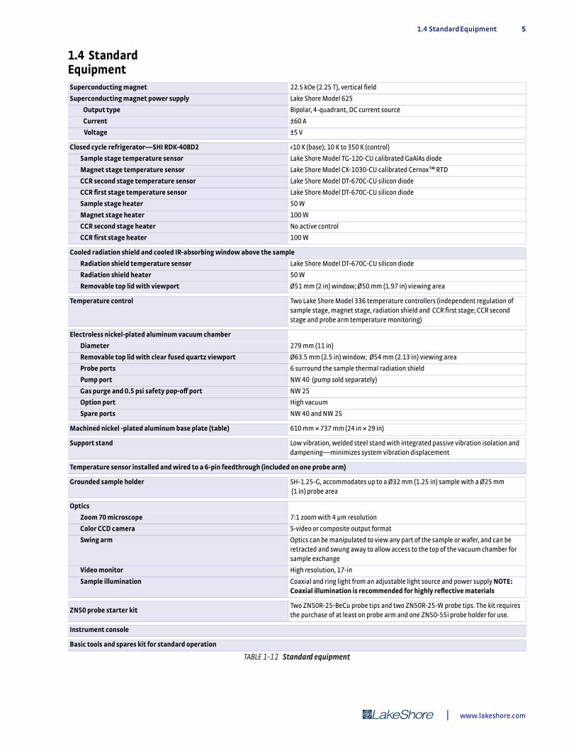
1.4 Standard EquipmentSuperconducting magnet 22.5 kOe (2.25 T), vertical field
Superconducting magnet power supply Lake Shore Model 625
Output type Bipolar, 4-quadrant, DC current source
Current ±60 A
Voltage ±5 V
Closed cycle refrigerator—SHI RDK-408D2 <10 K (base); 10 K to 350 K (control)
Sample stage temperature sensor Lake Shore Model TG-120-CU calibrated GaAlAs diode
Magnet stage temperature sensor Lake Shore Model CX-1030-CU calibrated Cernox™ RTD
CCR second stage temperature sensor Lake Shore Model DT-670C-CU silicon diode
CCR first stage temperature sensor Lake Shore Model DT-670C-CU silicon diode
Sample stage heater 50 W
Magnet stage heater 100 W
CCR second stage heater No active control
CCR first stage heater 100 W
Cooled radiation shield and cooled IR-absorbing window above the sample
Radiation shield temperature sensor Lake Shore Model DT-670C-CU silicon diode
Radiation shield heater 50 W
Removable top lid with viewport Ø51 mm (2 in) window; Ø50 mm (1.97 in) viewing area
Temperature control Two Lake Shore Model 336 temperature controllers (independent regulation of sample stage, magnet stage, radiation shield and CCR first stage; CCR second stage and probe arm temperature monitoring)
Electroless nickel-plated aluminum vacuum chamber
Diameter 279 mm (11 in)
Removable top lid with clear fused quartz viewport Ø63.5 mm (2.5 in) window; Ø54 mm (2.13 in) viewing area
Probe ports 6 surround the sample thermal radiation shield
Pump port NW 40 (pump sold separately)
Gas purge and 0.5 psi safety pop-off port NW 25
Option port High vacuum
Spare ports NW 40 and NW 25
Machined nickel -plated aluminum base plate (table) 610 mm × 737 mm (24 in × 29 in)
Support stand Low vibration, welded steel stand with integrated passive vibration isolation and dampening—minimizes system vibration displacement
Temperature sensor installed and wired to a 6-pin feedthrough (included on one probe arm)
Grounded sample holder SH-1.25-G, accommodates up to a Ø32 mm (1.25 in) sample with a Ø25 mm (1 in) probe area
Optics
Zoom 70 microscope 7:1 zoom with 4 µm resolution
Color CCD camera S-video or composite output format
Swing arm Optics can be manipulated to view any part of the sample or wafer, and can be retracted and swung away to allow access to the top of the vacuum chamber for sample exchange
Video monitor High resolution, 17-in
Sample illumination Coaxial and ring light from an adjustable light source and power supply NOTE: Coaxial illumination is recommended for highly reflective materials
ZN50 probe starter kitTwo ZN50R-25-BeCu probe tips and two ZN50R-25-W probe tips. The kit requires the purchase of at least on probe arm and one ZN50-55i probe holder for use.
Instrument console
Basic tools and spares kit for standard operation
TABLE 1-12 Standard equipment
| www.lakeshore.com

6 cHAPTER 1: Introduction
1.5 Required User Configurable Equipment
Micro-manipulated Stages, Probes, Probe Tips and CablesWe understand that today’s researcher requires flexibility. Our wide selection of probes, cables, sample holders, and options make it possible to configure a probe sta-tion to meet your specific measurement applications.
1.5.1 Up to Six XYZ Precision Micro-manipulated Stages
.
1.5.2 ZN50 DC/RF Probes
The ZN50 DC/RF probes are ideal for DC biasing, low/high frequency measurements, low noise shielded, and low-leakage guarded measurements. The ZN50 probe base incorporates a pair of copper braids that anchor to the magnet stage to minimize heat loss. The SMA connector is mounted directly to a replaceable alumina ceramic blade with a 50 ) stripline routed to the probe contact.
The following tables provide specifications for the ZN50 DC/RF probes. You can find more information on the ZN50 DC/RF probes in section 2.3.2 and application infor-mation in section 2.4.
Part Number Description
MMS-09Micro-manipulated stage with thermal radiation shields, stainless steel welded bellows, and feedthrough ports—includes probe arm and base; probes, probe tips and cables sold separately
TABLE 1-13 Micro-manipulated stage
Part number (probe body) Description
ZN50-55i50 ) stripline probe body mount (each probe body mount requires a ceramic blade—select-able below)
TABLE 1-14 ZN50 probe body
Part number (ceramic blade)
Tip material
Maximum frequency (GHz)
Maximum probe temperature*
Maximum sample temperature
Tip radius (μm)
ZN50R-03-W
Tungsten 1 Maximum frequency
50 MHz with ZN50C-G or ZN50C-T cable; maximum
frequency 1 GHz with
MWC-09-00K-NM cable
350 K 500 K
3
ZN50R-10-W 10
ZN50R-25-W 25
ZN50R-03-P7
Paliney 7
3
ZN50R-10-P7 10
ZN50R-25-P7 25
ZN50R-03-BECU
BeCu
3
ZN50R-10-BECU 10
ZN50R-25-BECU 25
ZN50R-100-BECU 100
ZN50R-200-BECU 200
*As measured by the probe arm temperature sensor
TABLE 1-15 ZN50 probe tips
Model CRX-VF Probe Station

1.5.3 ZN50 DC/RF Cables 7
1.5.3 ZN50 DC/RF Cables
1.5.4 GSG Microwave Probes
D Coplanar waveguide probe with ground-signal-ground (GSG) contact geometry
D User-specified pitch (spacing)D Optimized low thermal conductivity coaxial leading to low thermal
conductivity tipsD Include a copper braid assembly to cool the probe to near sample temperatureD Limited to 400 KD Separate planarization module with ±5° rotation mechanism is provided
1.5.5 GSG Microwave Cables
D Loss-less compression sealD Semirigid with Teflon® dielectric
Part number Cable typeConnector
typeFeedthrough
typeMeasurement configuration
Maximum frequency
Maximum cable temperature*
Maximum sample temperature**
ZN50C-GUltra-miniature
cryogenic coaxialSMA BNC Shielded 50 MHz
350 K 500 KZN50C-T
Ultra-miniature cryogenic coaxial
SMA 3-lug triaxial Low leakage 50 MHz
HMWC-09-00K-NM
Non-magnetic semirigid
microwave coaxial
K (SMA compatible)
Loss-less compression
sealHigh frequency 1 GHz†
*As measured by the probe arm temperature sensor† S21 > -10 dB up to 1 GHz, except for a (-40 dB) spike between 400 MHz and 800 MHz depending on probe model and placement; S11 < -3 dB up to 1 GHz
TABLE 1-16 ZN50 DC/RF cables
Part number Connector typeMaximum frequency
(GHz)
Maximum probe
temperature*
Maximum sample
temperaturePitch (μm)
GSG-050-40A-55I-E-NM
K 40
350 K 500 K
50
GSG-100-40A-55I-E-NM 100
GSG-150-40A-55I-E-NM 150
GSG-200-40A-55I-E-NM 200
GSG-250-40A-55I-E-NM 250
GSG-050-67A-55I-E-NM
1.85 mm 67
50
GSG-100-67A-55I-E-NM 100
GSG-150-67A-55I-E-NM 150
GSG-200-67A-55I-E-NM 200
GSG-250-67A-55I-E-NM 250
*As measured by the probe arm temperature sensor
TABLE 1-17 GSG microwave probes
Part number Cable typeFeedthrough
type
Maximum probe
temperature*
Maximum sample
temperatureConnector type
Maximum frequency
HMWC- 09-00K-NM
Non-magnetic semirigid
microwave coaxial
Loss-less compression
seal350 K 500 K
K (SMA compatible)
40 GHz
HMWC- 09-185-NM
1.85 mm 67 GHz
*As measured by the probe arm temperature sensor
TABLE 1-18 GSG microwave cables
| www.lakeshore.com
8 cHAPTER 1: Introduction
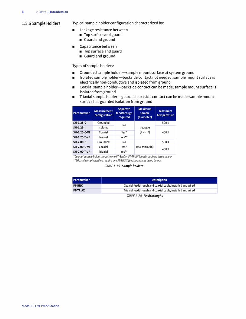
1.5.6 Sample Holders Typical sample holder configuration characterized by:
D Leakage resistance betweenD Top surface and guardD Guard and ground
D Capacitance betweenD Top surface and guardD Guard and ground
Types of sample holders:
D Grounded sample holder—sample mount surface at system groundD Isolated sample holder—backside contact not needed; sample mount surface is
electrically non-conductive and isolated from groundD Coaxial sample holder—backside contact can be made; sample mount surface is
isolated from groundD Triaxial sample holder—guarded backside contact can be made; sample mount
surface has guarded isolation from ground
Part numberMeasurement configuration
Separate feedthrough
required
Maximum sample
(diameter)
Maximum temperature
SH-1.25-G GroundedNo
Ø32 mm (1.25 in)
500 K
SH-1.25-I Isolated
400 KSH-1.25-C-VF Coaxial Yes*
SH-1.25-T-VF Triaxial Yes**
SH-2.00-G Grounded No
Ø51 mm (2 in)
500 K
SH-2.00-C-VF Coaxial Yes*400 K
SH-2.00-T-VF Triaxial Yes**
*Coaxial sample holders require one FT-BNC or FT-TRIAX feedthrough as listed below **Triaxial sample holders require one FT-TRIAX feedthrough as listed below
TABLE 1-19 Sample holders
Part number Description
FT-BNC Coaxial feedthrough and coaxial cable, installed and wired
FT-TRIAX Triaxial feedthrough and coaxial cable, installed and wired
TABLE 1-20 Feedthroughs
Model CRX-VF Probe Station
1.6 Equipment Options 9
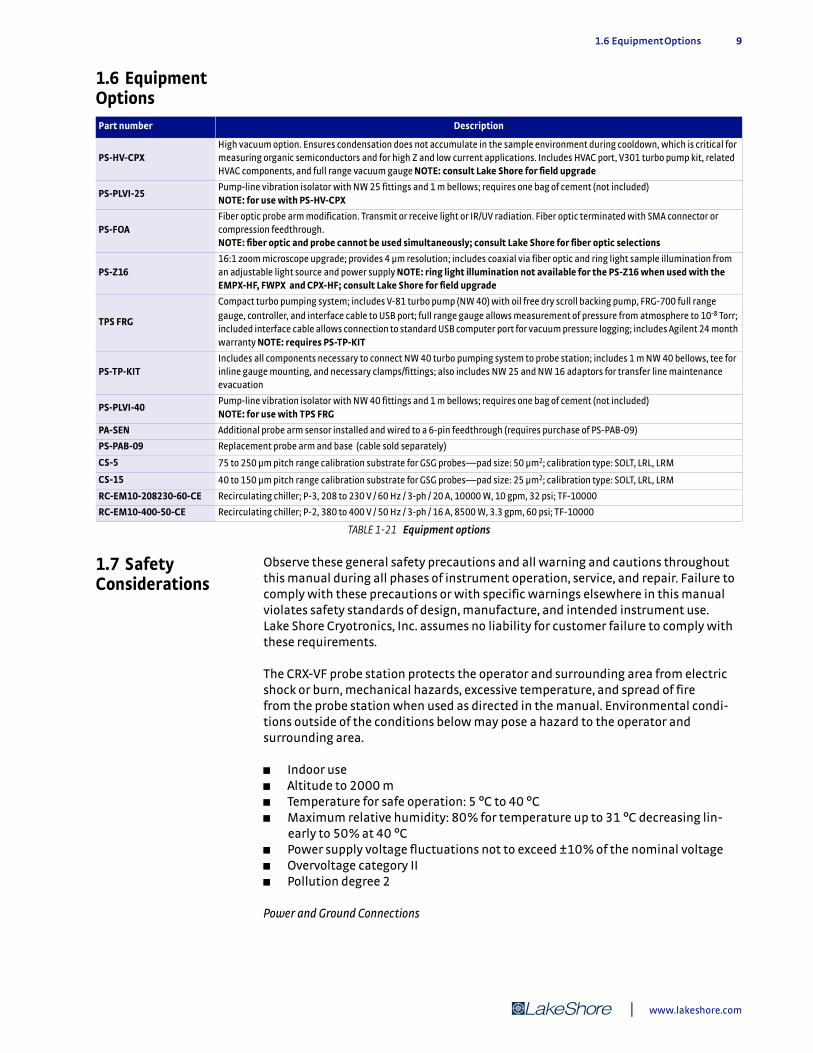
1.6 Equipment Options
1.7 Safety Considerations
Observe these general safety precautions and all warning and cautions throughout this manual during all phases of instrument operation, service, and repair. Failure to comply with these precautions or with specific warnings elsewhere in this manual violates safety standards of design, manufacture, and intended instrument use. Lake Shore Cryotronics, Inc. assumes no liability for customer failure to comply with these requirements.
The CRX-VF probe station protects the operator and surrounding area from electric shock or burn, mechanical hazards, excessive temperature, and spread of fire from the probe station when used as directed in the manual. Environmental condi-tions outside of the conditions below may pose a hazard to the operator and surrounding area.
D Indoor useD Altitude to 2000 mD Temperature for safe operation: 5 °C to 40 °CD Maximum relative humidity: 80% for temperature up to 31 °C decreasing lin-
early to 50% at 40 °CD Power supply voltage fluctuations not to exceed ±10% of the nominal voltageD Overvoltage category IID Pollution degree 2 Power and Ground Connections
Part number Description
PS-HV-CPXHigh vacuum option. Ensures condensation does not accumulate in the sample environment during cooldown, which is critical for measuring organic semiconductors and for high Z and low current applications. Includes HVAC port, V301 turbo pump kit, related HVAC components, and full range vacuum gauge NOTE: consult Lake Shore for field upgrade
PS-PLVI-25Pump-line vibration isolator with NW 25 fittings and 1 m bellows; requires one bag of cement (not included) NOTE: for use with PS-HV-CPX
PS-FOAFiber optic probe arm modification. Transmit or receive light or IR/UV radiation. Fiber optic terminated with SMA connector or compression feedthrough. NOTE: fiber optic and probe cannot be used simultaneously; consult Lake Shore for fiber optic selections
PS-Z1616:1 zoom microscope upgrade; provides 4 µm resolution; includes coaxial via fiber optic and ring light sample illumination from an adjustable light source and power supply NOTE: ring light illumination not available for the PS-Z16 when used with the EMPX-HF, FWPX and CPX-HF; consult Lake Shore for field upgrade
TPS FRG
Compact turbo pumping system; includes V-81 turbo pump (NW 40) with oil free dry scroll backing pump, FRG-700 full range gauge, controller, and interface cable to USB port; full range gauge allows measurement of pressure from atmosphere to 10-8 Torr; included interface cable allows connection to standard USB computer port for vacuum pressure logging; includes Agilent 24 month warranty NOTE: requires PS-TP-KIT
PS-TP-KITIncludes all components necessary to connect NW 40 turbo pumping system to probe station; includes 1 m NW 40 bellows, tee for inline gauge mounting, and necessary clamps/fittings; also includes NW 25 and NW 16 adaptors for transfer line maintenance evacuation
PS-PLVI-40Pump-line vibration isolator with NW 40 fittings and 1 m bellows; requires one bag of cement (not included) NOTE: for use with TPS FRG
PA-SEN Additional probe arm sensor installed and wired to a 6-pin feedthrough (requires purchase of PS-PAB-09)
PS-PAB-09 Replacement probe arm and base (cable sold separately)
CS-5 75 to 250 µm pitch range calibration substrate for GSG probes—pad size: 50 µm2; calibration type: SOLT, LRL, LRM
CS-15 40 to 150 µm pitch range calibration substrate for GSG probes—pad size: 25 µm2; calibration type: SOLT, LRL, LRM
RC-EM10-208230-60-CE Recirculating chiller; P-3, 208 to 230 V / 60 Hz / 3-ph / 20 A, 10000 W, 10 gpm, 32 psi; TF-10000
RC-EM10-400-50-CE Recirculating chiller; P-2, 380 to 400 V / 50 Hz / 3-ph / 16 A, 8500 W, 3.3 gpm, 60 psi; TF-10000
TABLE 1-21 Equipment options
| www.lakeshore.com

10 cHAPTER 1: Introduction
1-phase: to minimize shock hazard, the instrument console is equipped with a 3-con-ductor AC power cable. Plug the power cable into an approved 3-contact electrical outlet or use a 3-contact adapter with the grounding wire (green) firmly connected to an electrical ground (safety ground) at the power outlet.
3-phase: the CCR compressor must be connected to a dedicated 3-phase power circuit with proper size circuit breaker. Verify that the unit has been configured for the cor-rect input voltage. The neutral line, if available, is not used. The unit may be hard-wired or connected with a flexible cable and plug. In all cases, the correct size wire must be chosen for the current drawn and the length of cable used. To minimize shock hazard, the electrical ground (safety ground) lead must be connected. If a flexible cable and plug are used, plug the power cable into an approved electrical outlet. Power wiring must comply with electrical codes of the locality in which the unit is installed. The power jack and mating plug of the power cable meet Underwriters Lab-oratories (UL) and International Electrotechnical Commission (IEC) safety standards.
VentilationThe instrument console has ventilation holes. Do not block these holes when the instruments are operating.
Do Not Operate in an Explosive AtmosphereDo not operate the probe station in the presence of flammable gases or fumes. Opera-tion of any electrical instrument in such an environment constitutes a definite safety hazard.
Do Not Substitute Parts or Modify Station ComponentsDo not install substitute parts or perform any unauthorized modification to the probe station. Return it to an authorized Lake Shore Cryotronics, Inc. representative for ser-vice and repair to ensure that safety features are maintained.
CleaningClean only as directed in section 6.2.
FIGURE 1-1 Safety symbols
!
Direct current (power line) Equipment protected throughout by double insulation or reinforces insulation (equivalent to Class II of IEC 536—see Annex H)
CAUTION: High voltages; danger of electric shock; background color: yellow; symbol and outline: black
CAUTION or WARNING: See instrument documentation; background color: yellow; symbol and outline: black
Off (supply)
On (supply)
Frame or chassis terminal
Protective conductor terminal
Earth (ground) terminal
3 Three-phase alternating current (power line)
Alternating or direct current (power line)
Alternating current (power line)
Model CRX-VF Probe Station
2.1 General 11
Chapter 2: System Overview
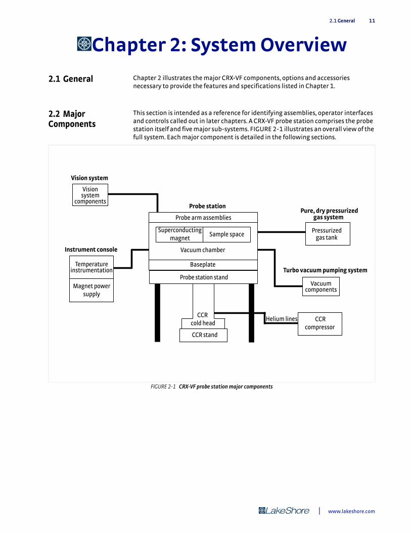
2.1 General Chapter 2 illustrates the major CRX-VF components, options and accessories necessary to provide the features and specifications listed in Chapter 1.
2.2 Major Components
This section is intended as a reference for identifying assemblies, operator interfaces and controls called out in later chapters. A CRX-VF probe station comprises the probe station itself and five major sub-systems. FIGURE 2-1 illustrates an overall view of the full system. Each major component is detailed in the following sections.
FIGURE 2-1 CRX-VF probe station major components
Vision system
Visionsystem
components
Instrument console
Probe arm assemblies
Sample space
Vacuum chamber
Baseplate
Pure, dry pressurized gas system
Turbo vacuum pumping system
Probe station
Temperature instrumentation
Vacuum components
Pressurized gas tank
CCR stand
CCRcompressor
Probe station stand
CCR cold head
Helium lines
Magnet powersupply
Superconductingmagnet
| www.lakeshore.com

12 CHAPTER 2: System Overview
2.2.1 Probe Station The probe station provides the temperature measurement environment for the sample or device under test (DUT). It also provides the electrical and optical interface with the sample. Major components of the probe station include the vacuum chamber, superconducting magnet, sample cooling assembly, baseplate and outer stand, probe arm assemblies, two-stage closed cycle refrigerator (CCR), CCR stand, and ballast weights. FIGURE 2-2 illustrates the probe station components.
FIGURE 2-2 Probe station
CCR cold head
Vacuum chamber
Baseplate
Probe armassembly
Probe arm assembly
Sample cooling assembly
CCR stand
CCR second stage
Cryocooler vacuum shroud
CCR first stage
Vibrationdampeningfeet
Ballast weights
Superconductingmagnet
Model CRX-VF Probe Station

2.2.1 Probe Station 13
2.2.1.1 Vacuum Chamber and CCR Vacuum ShroudVacuum is important for two reasons. It provides thermal insulation for the cryogenic refrigeration used to cool the sample and radiation shield, and it also prevents particulates and air in the chamber from condensing on the sample, which may lead to sample contamination during measurements.
The vacuum chamber consists of the upper vacuum chamber which contains the sample space, and the lower CCR vacuum shroud which contains the CCR. The two are connected by a vibration isolation bellows. Major components of the vacuum chamber include the vacuum chamber, lid, chamber viewport, purge valve, pressure relief valve, electrical feedthroughs, and auxiliary gauge port. Major components of the CCR vacuum shroud are the vacuum isolation valve and the electrical feedthrough for the CCR thermometry. FIGURE 2-3 illustrates the vacuum chamber and CCR vacuum shroud.
FIGURE 2-3 Vacuum chamber and CCR vacuum shroud
Chamber viewportLid
Probe arm port
Pressurerelief valve
Auxillary gauge port (front)
Ports for electricalfeedthrough (located on the back
Vacuum isolation valve
Port for CCR electricalfeedthrough
Purge valve
CCR vacuum shroud
Vibration isolationbellows
Vacuum chamber
Heat switch control
| www.lakeshore.com

14 CHAPTER 2: System Overview
2.2.1.2 Sample Cooling AssemblyThe CRX-VF sample cooling assembly contains several features to optimize performance and efficiency. Major components of the sample cooling assembly include the two-stage CCR cold head, sample stage, magnet stage, radiation shield stage, heat switch, radiation shield, and radiation shield viewport. The CCR first stage cools the radiation shield and probes.
The manually operated heat switch allows thermal connection of the sample stage to either the magnet stage (Base position), the radiation shield stage (Rad position), or thermally open (Open position). The Base position is for sample operation at the coldest temperature range, the Rad position is for intermediate temperatures, and the Open position is for elevated temperatures. When the heat switch is in the Open position, the sample stage is cooled through a large thermal resistance to the radiation shield stage allowing for sample operation at temperatures well above the temperature necessary to operate the magnet.
A temperature sensor and resistive heating element on the sample stage provide a means for sample temperature control. Temperature sensors and heaters on the radiation shield, CCR first, and CCR second stages allow temperature monitoring and quick warm up to room temperature for sample exchange.
FIGURE 2-4 illustrates the sample cooling assembly.
FIGURE 2-4 Sample cooling assembly
Radiation shield viewport
Radiation shield
CCR second stageSensor: Si diodeHeater: none
Radiation shield stage
Sensor: Si diodeHeater: 50 W
Sample stage
Magnet stageSensor: Cernox™
Heater: 100 W
Heat switch control
CCR first stage
Sensor: Si diodeHeater: 100 W
Sample spacethermometry port CCR
thermometry port
Sample stageSensor: GaAs diodeHeater: 50 W
Vacuumchamberbase
Model CRX-VF Probe Station
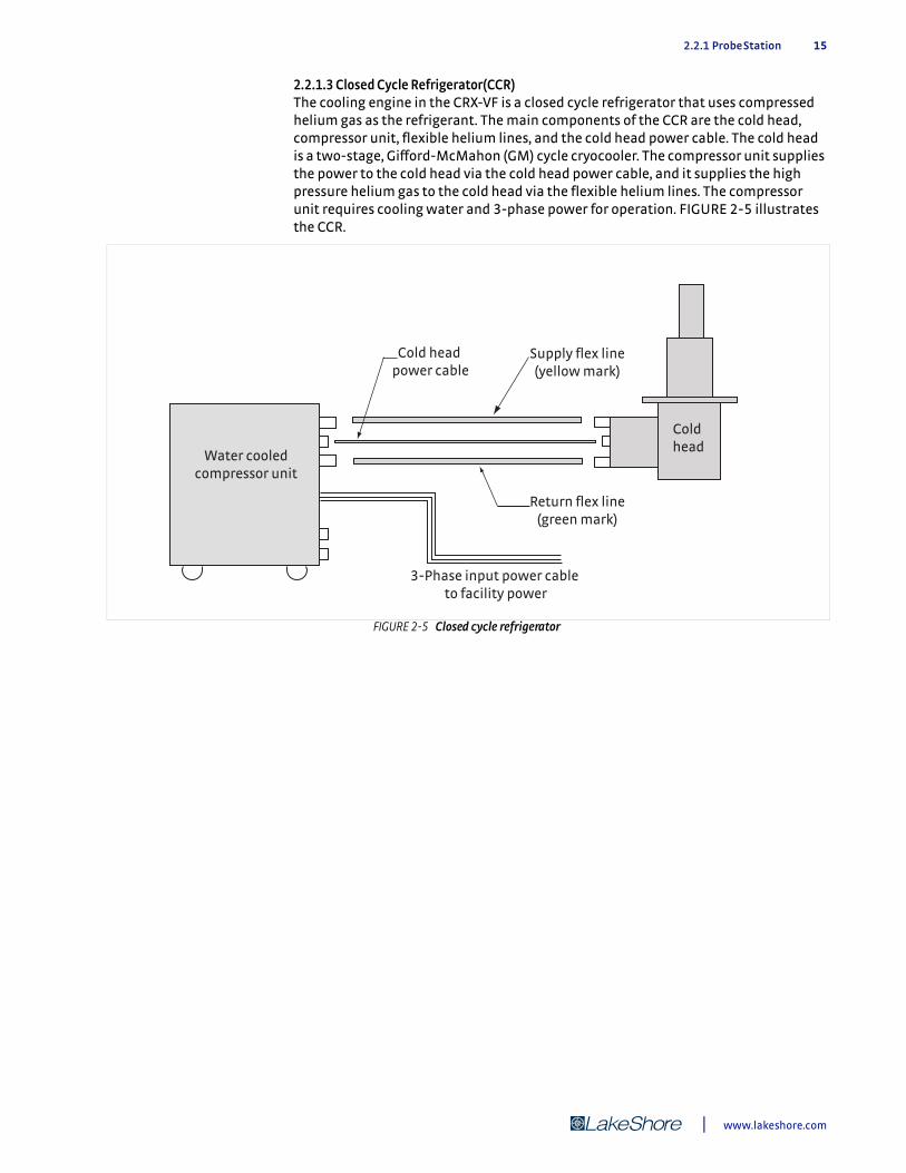
2.2.1 Probe Station 15
2.2.1.3 Closed Cycle Refrigerator(CCR)The cooling engine in the CRX-VF is a closed cycle refrigerator that uses compressed helium gas as the refrigerant. The main components of the CCR are the cold head, compressor unit, flexible helium lines, and the cold head power cable. The cold head is a two-stage, Gifford-McMahon (GM) cycle cryocooler. The compressor unit supplies the power to the cold head via the cold head power cable, and it supplies the high pressure helium gas to the cold head via the flexible helium lines. The compressor unit requires cooling water and 3-phase power for operation. FIGURE 2-5 illustrates the CCR.
FIGURE 2-5 Closed cycle refrigerator
3-Phase input power cable to facility power
Supply flex line(yellow mark)
Cold head power cable
Return flex line(green mark)
Water cooledcompressor unit
Cold head
| www.lakeshore.com
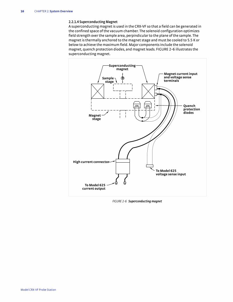
16 CHAPTER 2: System Overview
2.2.1.4 Superconducting MagnetA superconducting magnet is used in the CRX-VF so that a field can be generated in the confined space of the vacuum chamber. The solenoid configuration optimizes field strength over the sample area, perpindicular to the plane of the sample. The magnet is thermally anchored to the magnet stage and must be cooled to 5.5 K or below to achieve the maximum field. Major components include the solenoid magnet, quench protection diodes, and magnet leads. FIGURE 2-6 illustrates the superconducting magnet.
FIGURE 2-6 Superconducting magnet
High current connector
B
To Model 625 current output
Superconducting magnet
Magnet stage
To Model 625 voltage sense input
Quench protection diodes
Sample stage
Magnet current input and voltage sense terminals
Model CRX-VF Probe Station
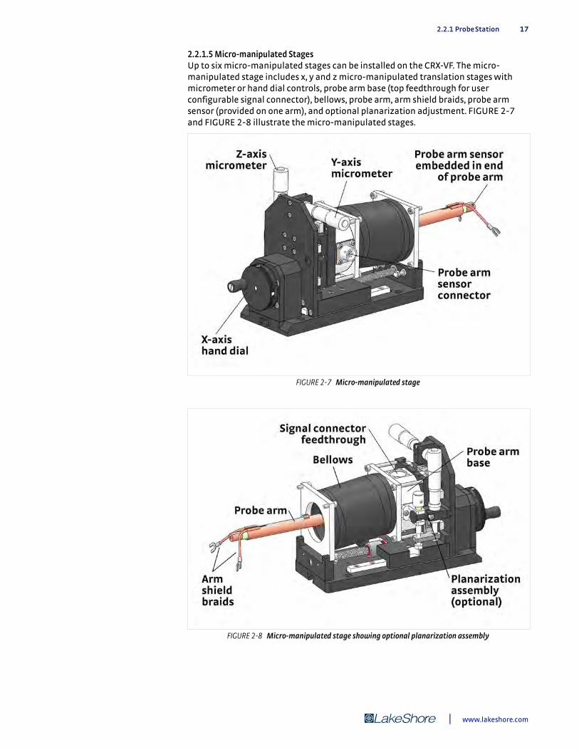
2.2.1 Probe Station 17
2.2.1.5 Micro-manipulated StagesUp to six micro-manipulated stages can be installed on the CRX-VF. The micro-manipulated stage includes x, y and z micro-manipulated translation stages with micrometer or hand dial controls, probe arm base (top feedthrough for user configurable signal connector), bellows, probe arm, arm shield braids, probe arm sensor (provided on one arm), and optional planarization adjustment. FIGURE 2-7 and FIGURE 2-8 illustrate the micro-manipulated stages.
FIGURE 2-7 Micro-manipulated stage
FIGURE 2-8 Micro-manipulated stage showing optional planarization assembly
| www.lakeshore.com
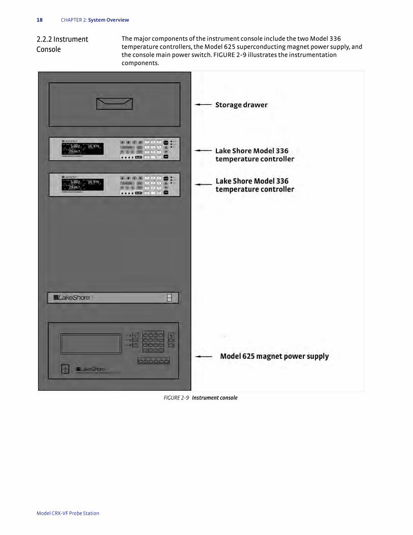
18 CHAPTER 2: System Overview
2.2.2 Instrument Console
The major components of the instrument console include the two Model 336 temperature controllers, the Model 625 superconducting magnet power supply, and the console main power switch. FIGURE 2-9 illustrates the instrumentation components.
FIGURE 2-9 Instrument console
Model CRX-VF Probe Station

2.2.2 Instrument Console 19
2.2.2.1 Temperature InstrumentationThe temperature instrumentation includes two Lake Shore Model 336 temperature controllers. The controllers are housed in the instrument console. FIGURE 2-10 and FIGURE 2-11 illustrate the temperature instrumentation and provide a summary of the probe station component that is monitored or controlled by each controller input.
FIGURE 2-10 Top Model 336 temperature controller
FIGURE 2-11 Bottom Model 336 temperature controller
| www.lakeshore.com
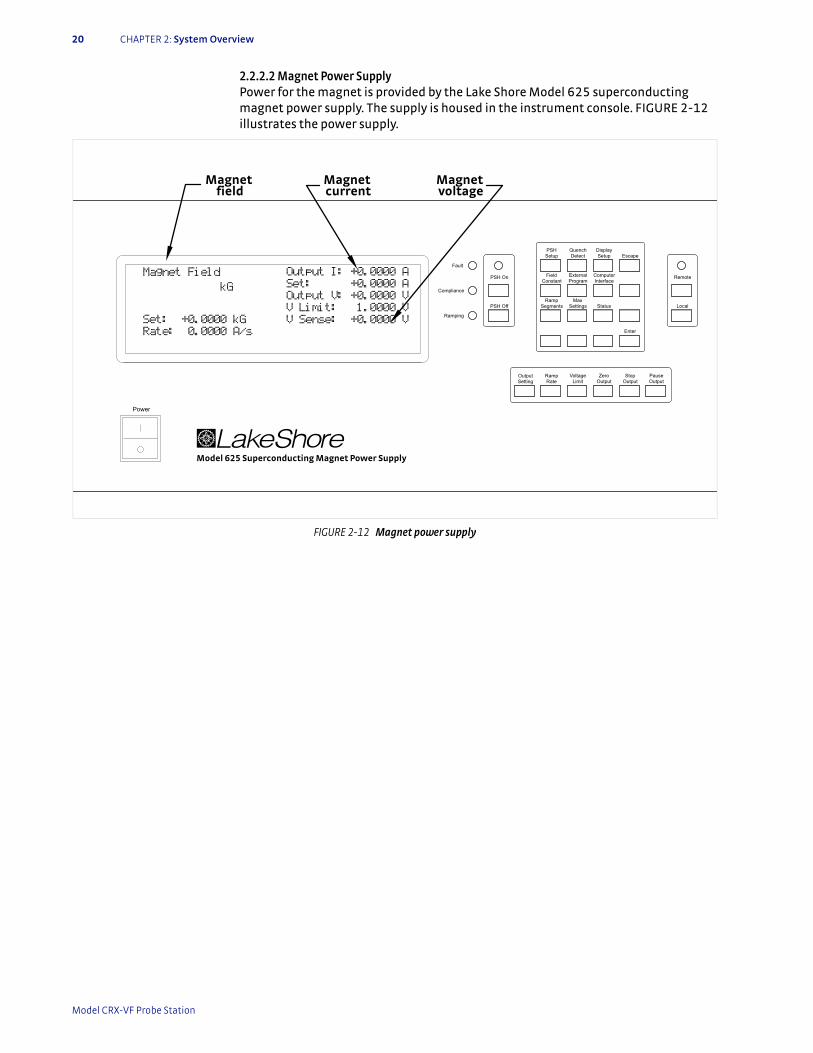
20 CHAPTER 2: System Overview
2.2.2.2 Magnet Power SupplyPower for the magnet is provided by the Lake Shore Model 625 superconducting magnet power supply. The supply is housed in the instrument console. FIGURE 2-12 illustrates the power supply.
FIGURE 2-12 Magnet power supply
Fault
Compliance
Ramping
PSH On
PSH Off
SettingOutput Ramp
RateVoltage
LimitZero
Output OutputStop Pause
Output
Remote
LocalSettingsMax
Status
Enter
InterfaceComputer
EscapeSetupDisplay
DetectQuenchPSH
Setup
Constant ProgramExternal
Power
Model 625 Superconducting Magnet Power Supply
Field
SegmentsRamp
Magnet Field Output I: +0.0000 A
Set: +0.0000 A
Output V: +0.0000 V
V Limit: 1.0000 V
V Sense: +0.0000 V
kG
Set: +0.0000 kG
Rate: 0.0000 A/s
Magnet field
Magnet current
Magnet voltage
Model CRX-VF Probe Station

2.2.3 Pressurized Gas System 21
2.2.3 Pressurized Gas System
The pressurized gas system typically includes the tank, output pressure regulator, pressure gauges and gas output. Pure, dry inert gas such as argon or nitrogen is recommended to purge the vacuum chamber. FIGURE 2-13 illustrates the pressurized gas system.
FIGURE 2-13 Pressurized gas system (profile)
Shut-off
Output pressure regulator
Output pressure gauge Tank pressure gauge
Pressurized gas tank
Gas output
| www.lakeshore.com

22 CHAPTER 2: System Overview
2.2.4 Vision System Major components of the vision system include the microscope, color CCD camera, monitor, support and adjustment apparatus, optical fiber cable, and light source. FIGURE 2-14 illustrates the vision system.
2.2.5 Turbo Pumping System (Optional TPS FRG or Equivalent)
Major components of the turbo pumping system typically include the controller, turbo pump, oil free dry scroll backing pump, vacuum gauge, and vent valve. FIGURE 2-15 illustrates the TPS FRG turbo pumping system.
FIGURE 2-14 Vision system (with ring light shown)
Hand dial
Microscope
Ring light
Viewport
Chamber
Monitor
Horizontal boom(swing arm)
S-videocable
Color CCD camera
Optical fiber cable
Lightsource
Vertical post
FIGURE 2-15 Turbo pumping system (vacuum gauge not shown)
0.5 m (17.6 in)
0.21 m (8.3 in)
NW 40
Model CRX-VF Probe Station
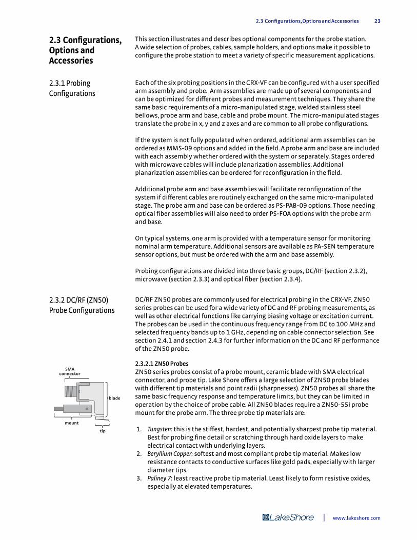
2.3 Configurations, Options and Accessories 23
2.3 Configurations, Options and Accessories
This section illustrates and describes optional components for the probe station. A wide selection of probes, cables, sample holders, and options make it possible to configure the probe station to meet a variety of specific measurement applications.
2.3.1 Probing Configurations
Each of the six probing positions in the CRX-VF can be configured with a user specified arm assembly and probe. Arm assemblies are made up of several components and can be optimized for different probes and measurement techniques. They share the same basic requirements of a micro-manipulated stage, welded stainless steel bellows, probe arm and base, cable and probe mount. The micro-manipulated stages translate the probe in x, y and z axes and are common to all probe configurations.
If the system is not fully populated when ordered, additional arm assemblies can be ordered as MMS-09 options and added in the field. A probe arm and base are included with each assembly whether ordered with the system or separately. Stages ordered with microwave cables will include planarization assemblies. Additional planarization assemblies can be ordered for reconfiguration in the field.
Additional probe arm and base assemblies will facilitate reconfiguration of the system if different cables are routinely exchanged on the same micro-manipulated stage. The probe arm and base can be ordered as PS-PAB-09 options. Those needing optical fiber assemblies will also need to order PS-FOA options with the probe arm and base.
On typical systems, one arm is provided with a temperature sensor for monitoring nominal arm temperature. Additional sensors are available as PA-SEN temperature sensor options, but must be ordered with the arm and base assembly.
Probing configurations are divided into three basic groups, DC/RF (section 2.3.2), microwave (section 2.3.3) and optical fiber (section 2.3.4).
2.3.2 DC/RF (ZN50) Probe Configurations
DC/RF ZN50 probes are commonly used for electrical probing in the CRX-VF. ZN50 series probes can be used for a wide variety of DC and RF probing measurements, as well as other electrical functions like carrying biasing voltage or excitation current. The probes can be used in the continuous frequency range from DC to 100 MHz and selected frequency bands up to 1 GHz, depending on cable connector selection. See section 2.4.1 and section 2.4.3 for further information on the DC and RF performance of the ZN50 probe.
2.3.2.1 ZN50 ProbesZN50 series probes consist of a probe mount, ceramic blade with SMA electrical connector, and probe tip. Lake Shore offers a large selection of ZN50 probe blades with different tip materials and point radii (sharpnesses). ZN50 probes all share the same basic frequency response and temperature limits, but they can be limited in operation by the choice of probe cable. All ZN50 blades require a ZN50-55i probe mount for the probe arm. The three probe tip materials are:
1. Tungsten: this is the stiffest, hardest, and potentially sharpest probe tip material. Best for probing fine detail or scratching through hard oxide layers to make electrical contact with underlying layers.
2. Beryllium Copper: softest and most compliant probe tip material. Makes low resistance contacts to conductive surfaces like gold pads, especially with larger diameter tips.
3. Paliney 7: least reactive probe tip material. Least likely to form resistive oxides, especially at elevated temperatures.
SMA connector
mount
blade
tip
| www.lakeshore.com
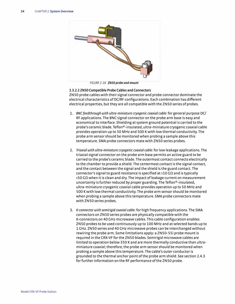
24 CHAPTER 2: System Overview
2.3.2.2 ZN50 Compatible Probe Cables and ConnectorsZN50 probe cables with their signal connector and probe connector dominate the electrical characteristics of DC/RF configurations. Each combination has different electrical properties, but they are all compatible with the ZN50 series of probes.
1. BNC feedthrough with ultra-miniature cryogenic coaxial cable: for general purpose DC/RF applications. The BNC signal connector on the probe arm base is easy and economical to interface. Shielding at system ground potential is carried to the probe’s ceramic blade. Teflon®-insulated, ultra-miniature cryogenic coaxial cable provides operation up to 50 MHz and 500 K with low thermal conductivity. The probe arm sensor should be monitored when probing a sample above this temperature. SMA probe connectors mate with ZN50 series probes.
2. Triaxial with ultra-miniature cryogenic coaxial cable: for low leakage applications. The triaxial signal connector on the probe arm base permits an active guard to be carried to the probe’s ceramic blade. The outermost contact connects electrically to the chamber to provide a shield. The centermost contact is the signal contact, and the contact between the signal and the shield is the guard contact. The connector’s signal to guard resistance is specified at >10 G) and is typically >50 G) when it is clean and dry. The impact of leakage current on measurement uncertainty is further reduced by proper guarding. The Teflon®-insulated, ultra-miniature cryogenic coaxial cable provides operation up to 50 MHz and 500 K with low thermal conductivity. The probe arm sensor should be monitored when probing a sample above this temperature. SMA probe connectors mate with ZN50 series probes.
3. K-connector with semirigid coaxial cable: for high frequency applications. The SMA connectors on ZN50 series probes are physically compatible with the K-connectors on 40 GHz microwave cables. This cable configuration enables ZN50 probes to be used continuously up to 100 MHz and at selected bands up to 1 GHz. ZN50 series and 40 GHz microwave probes can be interchanged without rewiring the probe arm. Some limitations apply: a ZN50-55i probe mount is required in the CRX-VF for the ZN50 blades. Semirigid microwave cables are limited to operation below 350 K and are more thermally conductive than ultra-miniature coaxial; therefore, the probe arm sensor should be monitored when probing a sample above this temperature. The cable’s outer conductor is grounded to the thermal anchor point of the probe arm shield. See section 2.4.3 for further information on the RF performance of the ZN50 probe.
FIGURE 2-16 ZN50 probe and mount
Model CRX-VF Probe Station

2.3.3 Microwave Probe Configurations 25
2.3.2.3 ZN50-Compatible Probe MountAll ZN50 series blades require a ZN50-55i probe mount that attaches to the probe arm and provides mechanical support and thermal anchoring for the blade. The probe mount braids provide the thermal anchoring. They can be connected to or disconnected from the sample stage as desired for a particular measurement application. When they are connected, the probe is maintained at approximately the same temperature as the anchor point.
2.3.3 Microwave Probe Configurations
Matching microwave probes and cables are available in two frequency ranges: DC to 40 GHz and DC to 67 GHz. Each frequency range uses a different connector type, but all use the same semirigid coaxial cable. Probe arm planarization is necessary to ensure simultaneous contact of all three points of the microwave probe tip. A planarization assembly is included on micro-manipulated stages when microwave cables are ordered, or it can be field installed.
2.3.3.1 Microwave-Compatible ProbesThere are two frequency configurations of microwave probes, determined by the connector used. The microwave probe must be specified with the same frequency and connector type as the probe cable. All microwave probes are constructed with ground-signal-ground (GSG) geometry and are designed for use with coplanar waveguides. The BeCu signal and ground points are 10 µm to 12 µm planar triangular structures. The pitch or spacing between the probe points can be specified from 50 µm to 250 µm in 50 µm increments. In general, smaller pitches are recommended for higher frequency applications. The point size is the same regardless of the probe pitch. The probes have a room temperature current limit of 2 A due to heat generated in the probe tip. Consult Lake Shore if this current limit is not sufficient for your application.
Separate probe mounts are not necessary for microwave probes because they are permanently mounted into a proprietary probe body. The proprietary microwave probe body is optimized for thermal performance in cryogenic probe stations and includes both mechanical support and thermal anchoring for the probe.
Microwave probe bodies must be kept below 350 K at all times, but due to the low thermal cross section of the probe points, the probe tips can safely probe substrates that are higher in temperature. Because the thermal anchor point for the probes are located on the radiation shield stage in the CRX-VF probe station, the microwave probes can safely probe a substrate on the sample stage up to 500 K as long as the probes are maintained at 350 K or less
FIGURE 2-17 Approximate
shape of microwave probe tip
G GS
FIGURE 2-18 Microwave probe
| www.lakeshore.com
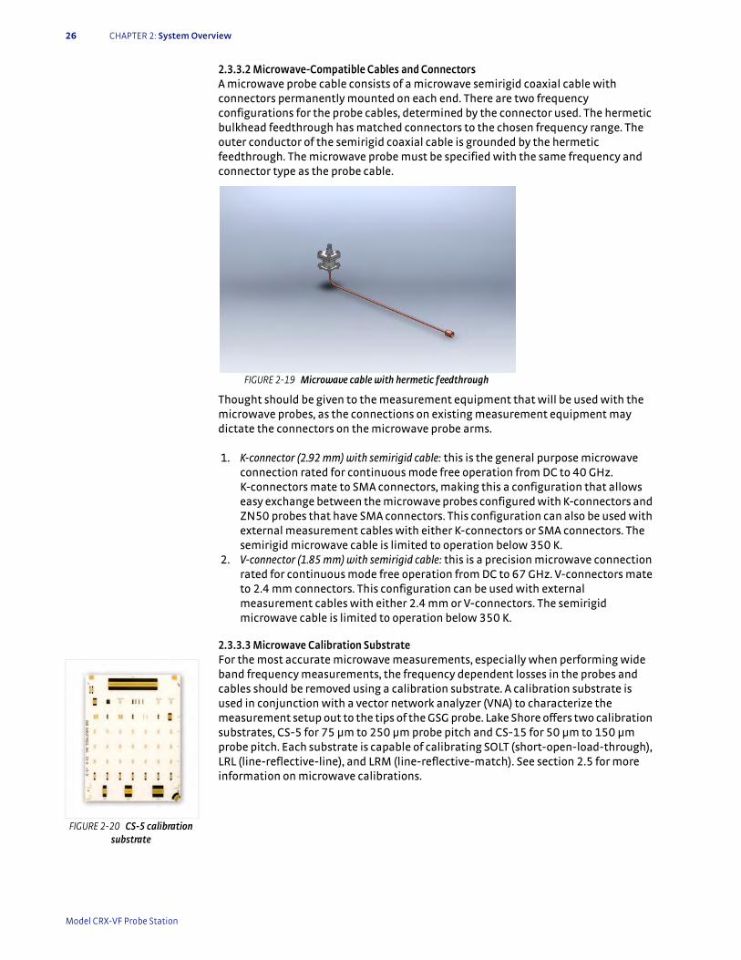
26 CHAPTER 2: System Overview
2.3.3.2 Microwave-Compatible Cables and ConnectorsA microwave probe cable consists of a microwave semirigid coaxial cable with connectors permanently mounted on each end. There are two frequency configurations for the probe cables, determined by the connector used. The hermetic bulkhead feedthrough has matched connectors to the chosen frequency range. The outer conductor of the semirigid coaxial cable is grounded by the hermetic feedthrough. The microwave probe must be specified with the same frequency and connector type as the probe cable.
Thought should be given to the measurement equipment that will be used with the microwave probes, as the connections on existing measurement equipment may dictate the connectors on the microwave probe arms.
1. K-connector (2.92 mm) with semirigid cable: this is the general purpose microwave connection rated for continuous mode free operation from DC to 40 GHz. K-connectors mate to SMA connectors, making this a configuration that allows easy exchange between the microwave probes configured with K-connectors and ZN50 probes that have SMA connectors. This configuration can also be used with external measurement cables with either K-connectors or SMA connectors. The semirigid microwave cable is limited to operation below 350 K.
2. V-connector (1.85 mm) with semirigid cable: this is a precision microwave connection rated for continuous mode free operation from DC to 67 GHz. V-connectors mate to 2.4 mm connectors. This configuration can be used with external measurement cables with either 2.4 mm or V-connectors. The semirigid microwave cable is limited to operation below 350 K.
2.3.3.3 Microwave Calibration SubstrateFor the most accurate microwave measurements, especially when performing wide band frequency measurements, the frequency dependent losses in the probes and cables should be removed using a calibration substrate. A calibration substrate is used in conjunction with a vector network analyzer (VNA) to characterize the measurement setup out to the tips of the GSG probe. Lake Shore offers two calibration substrates, CS-5 for 75 µm to 250 µm probe pitch and CS-15 for 50 µm to 150 µm probe pitch. Each substrate is capable of calibrating SOLT (short-open-load-through), LRL (line-reflective-line), and LRM (line-reflective-match). See section 2.5 for more information on microwave calibrations.
FIGURE 2-19 Microwave cable with hermetic feedthrough
FIGURE 2-20 CS-5 calibration substrate
Model CRX-VF Probe Station
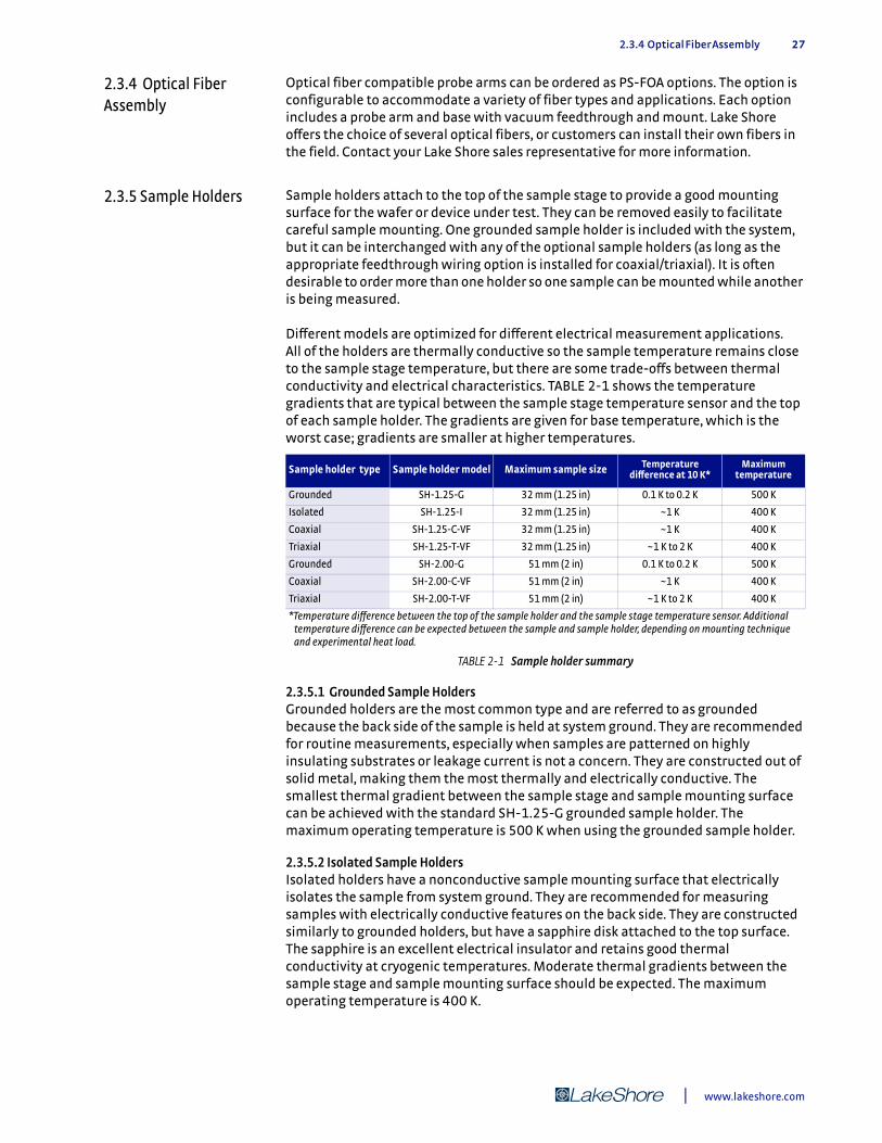
2.3.4 Optical Fiber Assembly 27
2.3.4 Optical Fiber Assembly
Optical fiber compatible probe arms can be ordered as PS-FOA options. The option is configurable to accommodate a variety of fiber types and applications. Each option includes a probe arm and base with vacuum feedthrough and mount. Lake Shore offers the choice of several optical fibers, or customers can install their own fibers in the field. Contact your Lake Shore sales representative for more information.
2.3.5 Sample Holders Sample holders attach to the top of the sample stage to provide a good mounting surface for the wafer or device under test. They can be removed easily to facilitate careful sample mounting. One grounded sample holder is included with the system, but it can be interchanged with any of the optional sample holders (as long as the appropriate feedthrough wiring option is installed for coaxial/triaxial). It is often desirable to order more than one holder so one sample can be mounted while another is being measured.
Different models are optimized for different electrical measurement applications. All of the holders are thermally conductive so the sample temperature remains close to the sample stage temperature, but there are some trade-offs between thermal conductivity and electrical characteristics. TABLE 2-1 shows the temperature gradients that are typical between the sample stage temperature sensor and the top of each sample holder. The gradients are given for base temperature, which is the worst case; gradients are smaller at higher temperatures.
2.3.5.1 Grounded Sample HoldersGrounded holders are the most common type and are referred to as grounded because the back side of the sample is held at system ground. They are recommended for routine measurements, especially when samples are patterned on highly insulating substrates or leakage current is not a concern. They are constructed out of solid metal, making them the most thermally and electrically conductive. The smallest thermal gradient between the sample stage and sample mounting surface can be achieved with the standard SH-1.25-G grounded sample holder. The maximum operating temperature is 500 K when using the grounded sample holder.
2.3.5.2 Isolated Sample HoldersIsolated holders have a nonconductive sample mounting surface that electrically isolates the sample from system ground. They are recommended for measuring samples with electrically conductive features on the back side. They are constructed similarly to grounded holders, but have a sapphire disk attached to the top surface. The sapphire is an excellent electrical insulator and retains good thermal conductivity at cryogenic temperatures. Moderate thermal gradients between the sample stage and sample mounting surface should be expected. The maximum operating temperature is 400 K.
Sample holder type Sample holder model Maximum sample size Temperature difference at 10 K*
Maximum temperature
Grounded SH-1.25-G 32 mm (1.25 in) 0.1 K to 0.2 K 500 K
Isolated SH-1.25-I 32 mm (1.25 in) ~1 K 400 K
Coaxial SH-1.25-C-VF 32 mm (1.25 in) ~1 K 400 K
Triaxial SH-1.25-T-VF 32 mm (1.25 in) ~1 K to 2 K 400 K
Grounded SH-2.00-G 51 mm (2 in) 0.1 K to 0.2 K 500 K
Coaxial SH-2.00-C-VF 51 mm (2 in) ~1 K 400 K
Triaxial SH-2.00-T-VF 51 mm (2 in) ~1 K to 2 K 400 K
*Temperature difference between the top of the sample holder and the sample stage temperature sensor. Additional temperature difference can be expected between the sample and sample holder, depending on mounting technique and experimental heat load.
TABLE 2-1 Sample holder summary
| www.lakeshore.com

28 CHAPTER 2: System Overview
2.3.5.3 Coaxial Sample HoldersCoaxial holders offer the ability to define the voltage potential on the conductive sample mounting surface in addition to isolating it from system ground. They are useful when it is desired to maintain the back side of a substrate at a potential other than chassis ground. They are recommended for applications such as guarding the sample to reduce leakage current, bringing a bias voltage to the back side of the sample or isolating and shielding the sample to reduce noise.
Coaxial holders are constructed as laminations of metal/insulator/metal in the sample plane. The conductive sample surface has a contact pin that can be driven at a user defined potential. Wiring for the sample holder requires an FT-BNC or FT-TRIAX feedthrough option. Moderate thermal gradients between the sample stage and sample mounting surface should be expected. The maximum operating temperature is 400 K.
2.3.5.4 Triaxial Sample HolderTriaxial holders offer the ability to define two different voltage potentials between the conductive sample mounting surface and system ground. They are recommended when two of the features supported by the coaxial sample holder are used at the same time. Examples include guarding to reduce leakage current and shielding to reduce noise or voltage biasing and guarding at the same time.
Triaxial holders are constructed as laminations of metal/insulator/metal/insulator/metal. The conductive sample surface and center metal plane both have contact pins that can be driven at user defined potentials. Wiring for these signals requires an FT-TRIAX feedthrough option. Moderate to medium thermal gradients between the sample stage and sample mounting surface should be expected. The maximum operating temperature is 400 K.
2.3.6 Vision System Configuration
The probe station’s vision system is critical for distinguishing characteristics of the sample and properly landing probes. The vision system can be optimized for the type of sample that is most frequently probed. There are four configurations available for the probe station, two different microscopes each with two lighting choices. The choice of an appropriate lighting type is especially important because it strongly influences the behavior of the vision system.
2.3.6.1 MicroscopesThere are two microscopes available for the probe station, the standard Zoom 70 and the optional Zoom 160. The Zoom 70 has a ratio of magnification change (zoom) of 7:1 and the Zoom 160 has a ratio of magnification change (zoom) of 16:1. The maximum magnification of the vision system is different than the magnification ratio. Vision system magnification is dependent on the microscope magnification and other factors such as the camera, monitor size and the optical elements necessary to overcome the probe station’s relatively large working distance. Resolution is often a more useful specification than magnification when choosing a microscope.
Lake Shore specifies resolution for the two different microscopes in Chapter 1. The specified resolution indicates the smallest feature that can be reasonably distinguished on the sample’s surface. (The sample’s texture and contrast also affect resolution.) Although the Zoom 160 always offers a higher magnification than the Zoom 70, the useable resolution of the two microscopes is often similar. This is primarily a result of the relatively large working distance between the microscope and sample, which limits the resolution of the Zoom 160. FIGURE 2-21 compares the resolution of the two microscopes under similar conditions in a TTPX probe station. Although the Zoom 160 image has visibly more resolution in this comparison, it is important to note that these results are difficult to duplicate during actual measurements. Factors such as the sample surface texture and normal levels of room
Model CRX-VF Probe Station

2.3.6 Vision System Configuration 29
vibration can quickly degrade the resolution of the Zoom 160 to match that of the Zoom 70.
2.3.6.2 Lighting TypesThere are two types of lights available for each microscope, coaxial and ring. The primary difference between the two is in the way light is reflected off of the sample surface into the microscope.
The coaxial light configuration guides light from the light source along the same path (coaxially) with the light returning from the sample. This allows the vision system to image very highly reflective samples such as those patterned on polished silicon. FIGURE 2-22 (left) is an image of four gold circles (10 µm to 100 µm in diameter) patterned on a highly reflective surface illuminated with a coaxial light. Although the image appears relatively flat and has modest contrast, it is more than adequate for properly landing probes. FIGURE 2-22 (right) is an image of the same sample illuminated with a ring light. The image is darker and even lower in contrast because nearly all of the light is cleanly reflected away from the microscope. It would be difficult to properly land a probe using this image.
The ring light surrounds the end of the microscope with light from the source which illuminates the sample from all directions. The light scatters as it reflects off of textured or uneven surfaces, giving images contrast and the appearance of a third dimension. FIGURE 2-23 (left) is an image of a surface mount device illuminated with a ring light. The natural appearance of the sample is preferred by many operators. FIGURE 2-23 (right) is an image of the same device illuminated with a coaxial light. Its
FIGURE 2-21 Left: Best case resolution (approximately 2 μm) obtained obtained with Zoom 160 and coaxial light on a TTPX probe station; Right: Typical resolution (approximately 3 μm) obtained with Zoom 70 and coaxial light on a TTPX probe station
FIGURE 2-22 Left: Highly reflective surface through a Zoom 70 with a coaxial light; Right: Highly reflective surface through a Zoom 70 with a ring light
| www.lakeshore.com
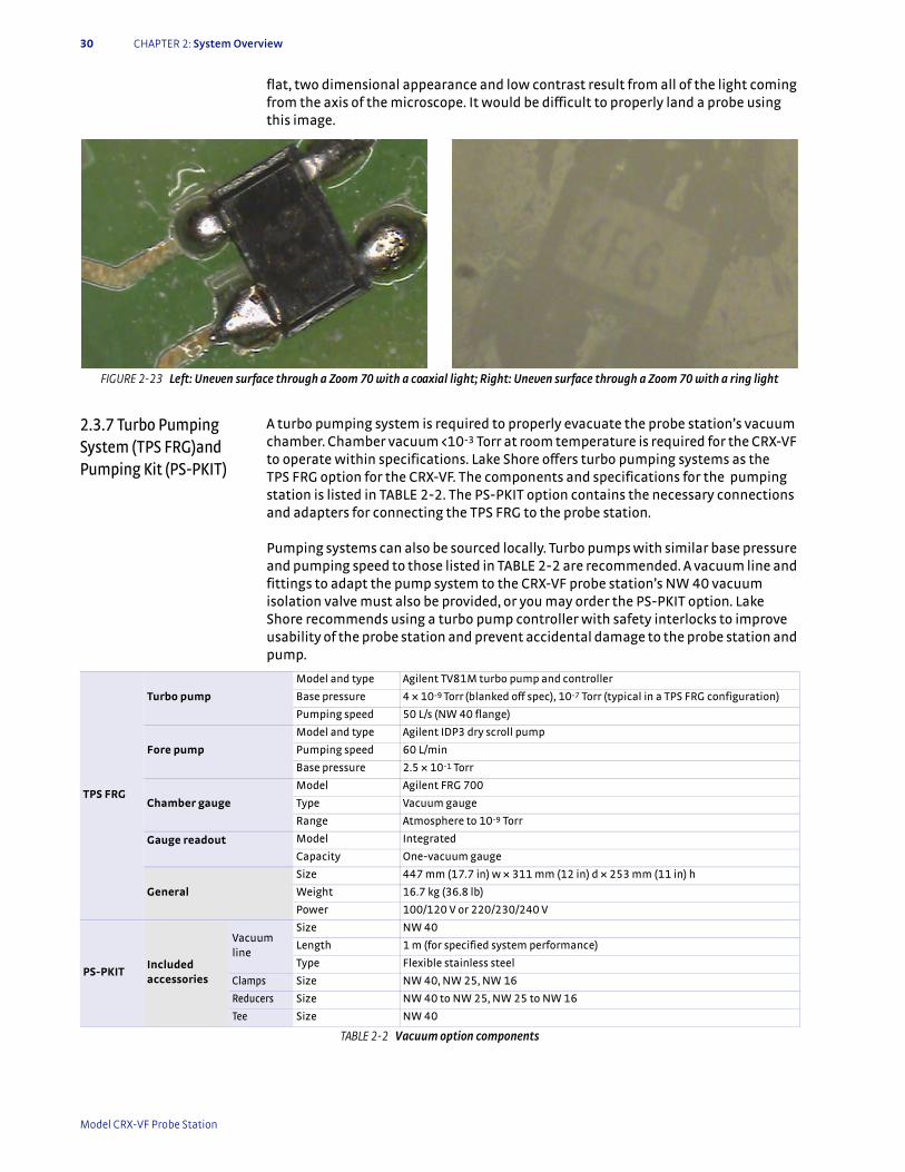
30 CHAPTER 2: System Overview
flat, two dimensional appearance and low contrast result from all of the light coming from the axis of the microscope. It would be difficult to properly land a probe using this image.
2.3.7 Turbo Pumping System (TPS FRG)and Pumping Kit (PS-PKIT)
A turbo pumping system is required to properly evacuate the probe station’s vacuum chamber. Chamber vacuum <10-3 Torr at room temperature is required for the CRX-VF to operate within specifications. Lake Shore offers turbo pumping systems as the TPS FRG option for the CRX-VF. The components and specifications for the pumping station is listed in TABLE 2-2. The PS-PKIT option contains the necessary connections and adapters for connecting the TPS FRG to the probe station.
Pumping systems can also be sourced locally. Turbo pumps with similar base pressure and pumping speed to those listed in TABLE 2-2 are recommended. A vacuum line and fittings to adapt the pump system to the CRX-VF probe station’s NW 40 vacuum isolation valve must also be provided, or you may order the PS-PKIT option. Lake Shore recommends using a turbo pump controller with safety interlocks to improve usability of the probe station and prevent accidental damage to the probe station and pump.
FIGURE 2-23 Left: Uneven surface through a Zoom 70 with a coaxial light; Right: Uneven surface through a Zoom 70 with a ring light
TPS FRG
Turbo pump
Model and type Agilent TV81M turbo pump and controller
Base pressure 4 × 10⁻⁹ Torr (blanked off spec), 10-7 Torr (typical in a TPS FRG configuration)
Pumping speed 50 L/s (NW 40 flange)
Fore pump
Model and type Agilent IDP3 dry scroll pump
Pumping speed 60 L/min
Base pressure 2.5 × 10⁻¹ Torr
Chamber gauge
Model Agilent FRG 700
Type Vacuum gauge
Range Atmosphere to 10-9 Torr
Gauge readout Model Integrated
Capacity One-vacuum gauge
General
Size 447 mm (17.7 in) w × 311 mm (12 in) d × 253 mm (11 in) h
Weight 16.7 kg (36.8 lb)
Power 100/120 V or 220/230/240 V
PS-PKITIncluded accessories
Vacuum line
Size NW 40
Length 1 m (for specified system performance)
Type Flexible stainless steel
Clamps Size NW 40, NW 25, NW 16
Reducers Size NW 40 to NW 25, NW 25 to NW 16
Tee Size NW 40
TABLE 2-2 Vacuum option components
Model CRX-VF Probe Station
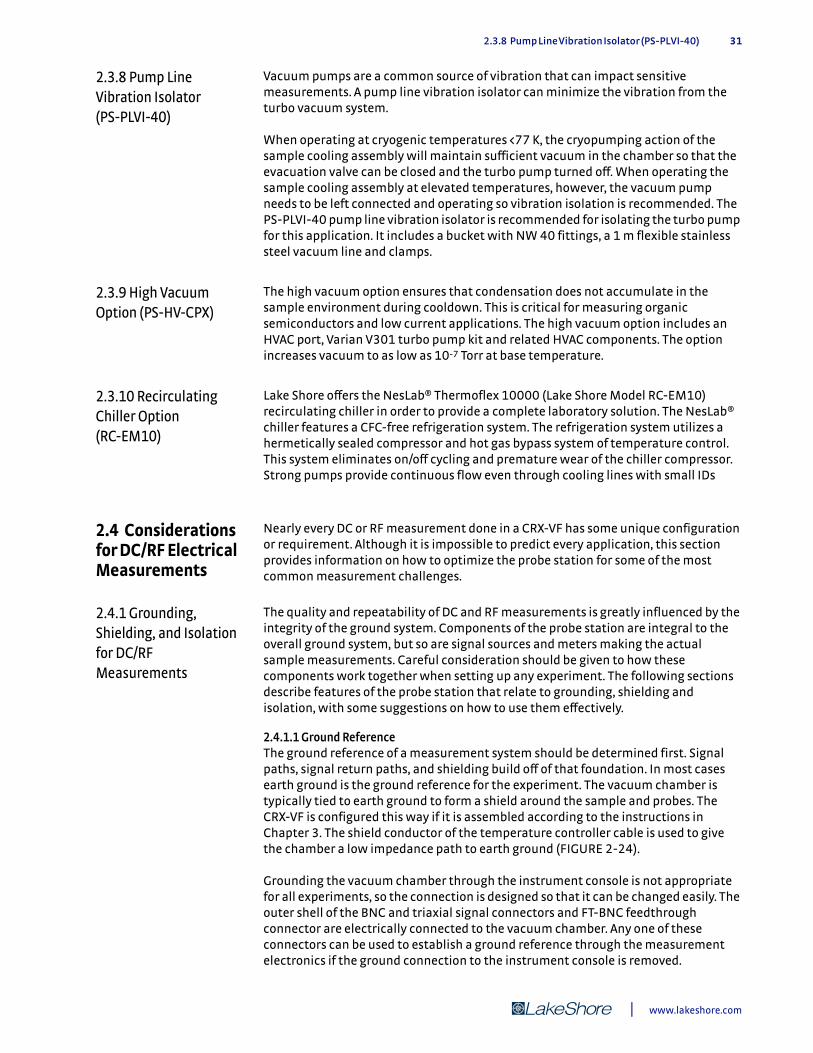
2.3.8 Pump Line Vibration Isolator (PS-PLVI-40) 31
2.3.8 Pump Line Vibration Isolator (PS-PLVI-40)
Vacuum pumps are a common source of vibration that can impact sensitive measurements. A pump line vibration isolator can minimize the vibration from the turbo vacuum system.
When operating at cryogenic temperatures <77 K, the cryopumping action of the sample cooling assembly will maintain sufficient vacuum in the chamber so that the evacuation valve can be closed and the turbo pump turned off. When operating the sample cooling assembly at elevated temperatures, however, the vacuum pump needs to be left connected and operating so vibration isolation is recommended. The PS-PLVI-40 pump line vibration isolator is recommended for isolating the turbo pump for this application. It includes a bucket with NW 40 fittings, a 1 m flexible stainless steel vacuum line and clamps.
2.3.9 High Vacuum Option (PS-HV-CPX)
The high vacuum option ensures that condensation does not accumulate in the sample environment during cooldown. This is critical for measuring organic semiconductors and low current applications. The high vacuum option includes an HVAC port, Varian V301 turbo pump kit and related HVAC components. The option increases vacuum to as low as 10-7 Torr at base temperature.
2.3.10 Recirculating Chiller Option (RC-EM10)
Lake Shore offers the NesLab® Thermoflex 10000 (Lake Shore Model RC-EM10) recirculating chiller in order to provide a complete laboratory solution. The NesLab® chiller features a CFC-free refrigeration system. The refrigeration system utilizes a hermetically sealed compressor and hot gas bypass system of temperature control. This system eliminates on/off cycling and premature wear of the chiller compressor. Strong pumps provide continuous flow even through cooling lines with small IDs
2.4 Considerations for DC/RF Electrical Measurements
Nearly every DC or RF measurement done in a CRX-VF has some unique configuration or requirement. Although it is impossible to predict every application, this section provides information on how to optimize the probe station for some of the most common measurement challenges.
2.4.1 Grounding, Shielding, and Isolation for DC/RF Measurements
The quality and repeatability of DC and RF measurements is greatly influenced by the integrity of the ground system. Components of the probe station are integral to the overall ground system, but so are signal sources and meters making the actual sample measurements. Careful consideration should be given to how these components work together when setting up any experiment. The following sections describe features of the probe station that relate to grounding, shielding and isolation, with some suggestions on how to use them effectively.
2.4.1.1 Ground ReferenceThe ground reference of a measurement system should be determined first. Signal paths, signal return paths, and shielding build off of that foundation. In most cases earth ground is the ground reference for the experiment. The vacuum chamber is typically tied to earth ground to form a shield around the sample and probes. The CRX-VF is configured this way if it is assembled according to the instructions in Chapter 3. The shield conductor of the temperature controller cable is used to give the chamber a low impedance path to earth ground (FIGURE 2-24).
Grounding the vacuum chamber through the instrument console is not appropriate for all experiments, so the connection is designed so that it can be changed easily. The outer shell of the BNC and triaxial signal connectors and FT-BNC feedthrough connector are electrically connected to the vacuum chamber. Any one of these connectors can be used to establish a ground reference through the measurement electronics if the ground connection to the instrument console is removed.
| www.lakeshore.com
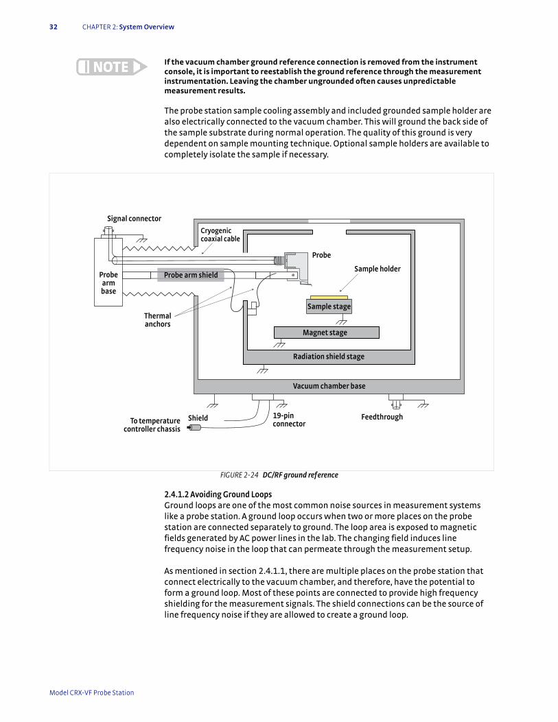
32 CHAPTER 2: System Overview
If the vacuum chamber ground reference connection is removed from the instrument console, it is important to reestablish the ground reference through the measurement instrumentation. Leaving the chamber ungrounded often causes unpredictable measurement results.
The probe station sample cooling assembly and included grounded sample holder are also electrically connected to the vacuum chamber. This will ground the back side of the sample substrate during normal operation. The quality of this ground is very dependent on sample mounting technique. Optional sample holders are available to completely isolate the sample if necessary.
2.4.1.2 Avoiding Ground LoopsGround loops are one of the most common noise sources in measurement systems like a probe station. A ground loop occurs when two or more places on the probe station are connected separately to ground. The loop area is exposed to magnetic fields generated by AC power lines in the lab. The changing field induces line frequency noise in the loop that can permeate through the measurement setup.
As mentioned in section 2.4.1.1, there are multiple places on the probe station that connect electrically to the vacuum chamber, and therefore, have the potential to form a ground loop. Most of these points are connected to provide high frequency shielding for the measurement signals. The shield connections can be the source of line frequency noise if they are allowed to create a ground loop.
FIGURE 2-24 DC/RF ground reference
Radiation shield stage
Probe
Sample stage
Sample holder
Cryogenic coaxial cable
Signal connector
Probe armbase
Probe arm shield
To temperature controller chassis
19-pinconnector
Feedthrough
Thermalanchors
Shield
Vacuum chamber base
Magnet stage
Model CRX-VF Probe Station

2.4.1 Grounding, Shielding, and Isolation for DC/RF Measurements 33
Minimizing the effect of ground loops can be difficult—some experimentation may be required to achieve the best results. One of the biggest difficulties is that signal sources and acquisition electronics often operate with one lead internally referenced to earth ground, so the overall grounding system must take this into account.
The best approach is to make the system a poor receiver for the noise:
Never remove earth safety ground protection from electronic equipment.
1. Electrically isolate any parts of the systems that do not require grounding for safety or performance.
2. Attach cable shields at only one end of the cable if the shield conductor is not being used to establish a return path for the signal.
3. Add resistance in series with reference ground leads in cases where some common mode voltage is present.
4. Reduce the loop area of any ground loops that remain by routing cables close together or twisting wires.
5. Make sure power lines to equipment have a direct, low impedance path to earth ground so that no voltage is present between equipment grounds.
6. Ground strap instrumentation chassis to provide low impedance between components of the system.
2.4.1.3 ShieldingShielding reduces noise induced in the probe cables by electric fields in the environment or other equipment in the experiment. The probe station’s vacuum chamber is the most important part of a shielding system. The electrically conductive chamber surrounds the sample area and is often connected to the measurement system’s ground reference as described in section 2.4.1.1 . BNC and triaxial signal connector shells are electrically connected to the chamber to provide a shield contact for cabling. DC/RF probe cables are all made from cryogenic, coaxial wire so the shielding can be carried inside the chamber and down the probe arm. Outside the chamber, shielding is recommended for all signal cables, but the shielding must not be allowed to create ground loops as described in section 2.4.1.2. It is often necessary to connect the shield at only one end of the cable.
2.4.1.4 Noise IsolationEvery attempt was made in the design and construction of the CRX-VF to isolate potential noise sources so they do not interfere with measurements. It is important to recognize these features so they are not inadvertently defeated when the probe station is re-configured or set up for measurements. Non-conductive components are used to attach the vacuum isolation valve to the vacuum chamber to prevent electrical noise emanating from the pump from entering through the vacuum line (bellows). The temperature sensors and control heaters are electrically isolated from the sample cooling assembly to prevent interference from the instrumentation. This isolation is sufficient for most probe station applications. Additional precautions may be necessary for very low noise measurements; see section 2.4.6.
| www.lakeshore.com
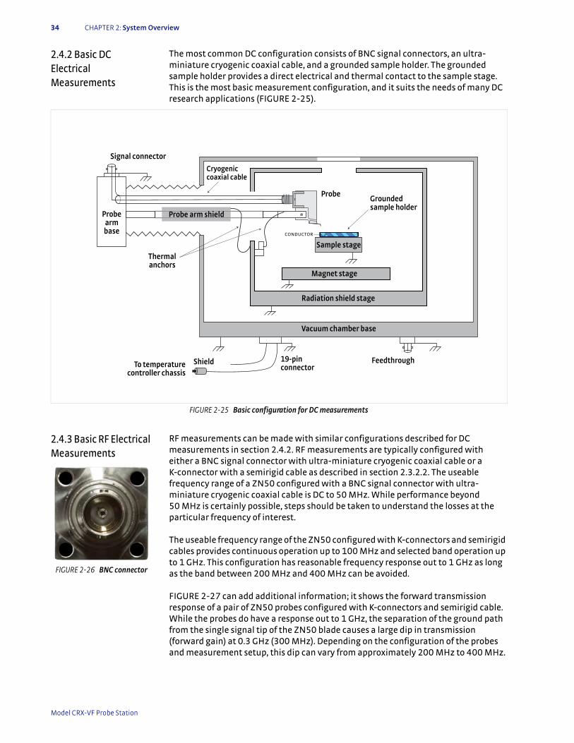
34 CHAPTER 2: System Overview
2.4.2 Basic DC Electrical Measurements
The most common DC configuration consists of BNC signal connectors, an ultra-miniature cryogenic coaxial cable, and a grounded sample holder. The grounded sample holder provides a direct electrical and thermal contact to the sample stage. This is the most basic measurement configuration, and it suits the needs of many DC research applications (FIGURE 2-25).
2.4.3 Basic RF Electrical Measurements
RF measurements can be made with similar configurations described for DC measurements in section 2.4.2. RF measurements are typically configured with either a BNC signal connector with ultra-miniature cryogenic coaxial cable or a K-connector with a semirigid cable as described in section 2.3.2.2. The useable frequency range of a ZN50 configured with a BNC signal connector with ultra-miniature cryogenic coaxial cable is DC to 50 MHz. While performance beyond 50 MHz is certainly possible, steps should be taken to understand the losses at the particular frequency of interest.
The useable frequency range of the ZN50 configured with K-connectors and semirigid cables provides continuous operation up to 100 MHz and selected band operation up to 1 GHz. This configuration has reasonable frequency response out to 1 GHz as long as the band between 200 MHz and 400 MHz can be avoided.
FIGURE 2-27 can add additional information; it shows the forward transmission response of a pair of ZN50 probes configured with K-connectors and semirigid cable. While the probes do have a response out to 1 GHz, the separation of the ground path from the single signal tip of the ZN50 blade causes a large dip in transmission (forward gain) at 0.3 GHz (300 MHz). Depending on the configuration of the probes and measurement setup, this dip can vary from approximately 200 MHz to 400 MHz.
FIGURE 2-25 Basic configuration for DC measurements
Radiation shield stage
Probe
Sample stage
Cryogenic coaxial cable
Signal connector
Probe armbase
Probe arm shield
To temperature controller chassis
19-pinconnector
Feedthrough
Thermalanchors
Shield
Vacuum chamber base
Magnet stage
Groundedsample holder
CONDUCTOR
FIGURE 2-26 BNC connector
Model CRX-VF Probe Station
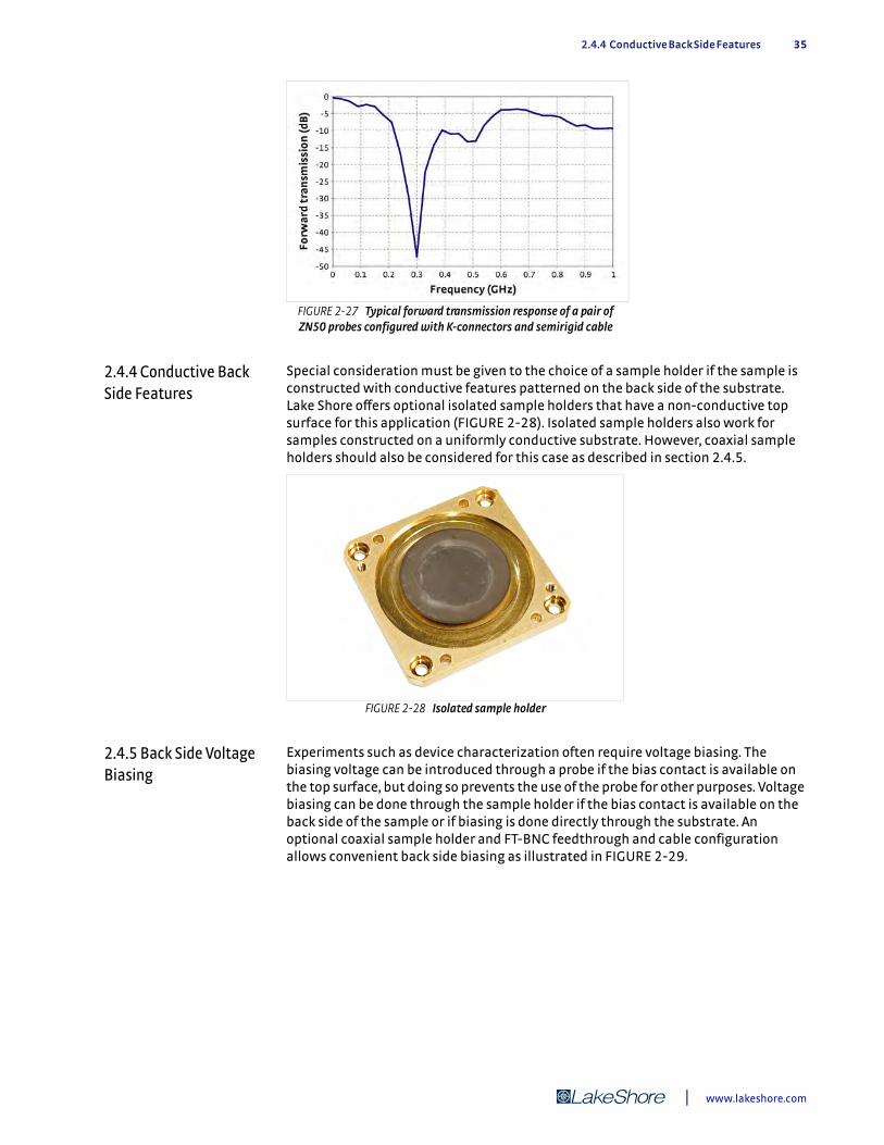
2.4.4 Conductive Back Side Features 35
2.4.4 Conductive Back Side Features
Special consideration must be given to the choice of a sample holder if the sample is constructed with conductive features patterned on the back side of the substrate. Lake Shore offers optional isolated sample holders that have a non-conductive top surface for this application (FIGURE 2-28). Isolated sample holders also work for samples constructed on a uniformly conductive substrate. However, coaxial sample holders should also be considered for this case as described in section 2.4.5.
2.4.5 Back Side Voltage Biasing
Experiments such as device characterization often require voltage biasing. The biasing voltage can be introduced through a probe if the bias contact is available on the top surface, but doing so prevents the use of the probe for other purposes. Voltage biasing can be done through the sample holder if the bias contact is available on the back side of the sample or if biasing is done directly through the substrate. An optional coaxial sample holder and FT-BNC feedthrough and cable configuration allows convenient back side biasing as illustrated in FIGURE 2-29.
FIGURE 2-27 Typical forward transmission response of a pair of ZN50 probes configured with K-connectors and semirigid cable
FIGURE 2-28 Isolated sample holder
| www.lakeshore.com
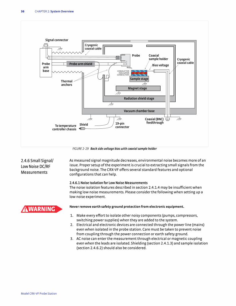
36 CHAPTER 2: System Overview
2.4.6 Small Signal/ Low Noise DC/RF Measurements
As measured signal magnitude decreases, environmental noise becomes more of an issue. Proper setup of the experiment is crucial to extracting small signals from the background noise. The CRX-VF offers several standard features and optional configurations that can help.
2.4.6.1 Noise Isolation for Low Noise MeasurementsThe noise isolation features described in section 2.4.1.4 may be insufficient when making low noise measurements. Please consider the following when setting up a low noise experiment.
Never remove earth safety ground protection from electronic equipment.
1. Make every effort to isolate other noisy components (pumps, compressors, switching power supplies) when they are added to the system.
2. Electrical and electronic devices are connected through the power line (mains) even when isolated in the probe station. Care must be taken to prevent noise from coupling through the power connection or earth safety ground.
3. AC noise can enter the measurement through electrical or magnetic coupling even when the leads are isolated. Shielding (section 2.4.1.3) and sample isolation (section 2.4.6.2) should also be considered.
FIGURE 2-29 Back side voltage bias with coaxial sample holder
Radiation shield stage
Probe
Sample stage
Cryogenic coaxial cable
Signal connector
Probe armbase
Probe arm shield
To temperature controller chassis
19-pinconnector
Thermalanchors
Shield
Vacuum chamber base
Magnet stage
CONDUCTORINSULATOR
CONDUCTOR
Cryogenic coaxial cable
Coaxialsample holder
Bias voltage
Coaxial (BNC) feedthrough
Model CRX-VF Probe Station
2.4.7 Measuring Low Resistance 37
2.4.6.2 Sample Isolation for Low Noise MeasurementsEven with proper setup and isolation of the electronics, it is sometimes impossible to reduce their interference with the sample when it is mounted on a grounded sample holder. One solution is to use an optional coaxial sample holder to isolate the sample from the grounded sample cooling assembly and vacuum chamber. The FT-BNC feedthrough and cable configuration can be used to bring a clean measurement ground reference directly to the sample plane. This configuration can both isolate and shield the sample (see FIGURE 2-29).
2.4.6.3 Additional Considerations for Low Noise MeasurementsWhen designing a small signal or low noise experiment it is important to consider more than the electronics. There are environmental factors that can limit measurement quality as well. Three of the most common are:
1. Contact quality: poor probe to sample contacts can cause noise, drift, and poor repeatability in measurements. Refer to section 2.6 for information on how to improve contact quality.
2. Temperature stability: the sample temperature changes relatively slowly in most applications and often does not contribute to measurement noise. Small signals tend to have longer measurement intervals due to averaging so they are more susceptible to temperature changes. It is important to properly tune the temperature controller to improve temperature stability. It is also important to allow the system to stabilize at the desired temperature longer before taking data. It often takes several minutes after the sample stage temperature sensor stabilizes before the sample comes to equilibrium.
Cryogenic experiments are most often designed to cool the system to base temperature first. Temperature is then increased between data points to provide the best sample temperature stability.
3. Vibration isolation: the vibration present in a typical probe station seldom contributes to measurement noise unless the probe to sample contact is poor. When making small signal measurements, the effect of vibration increases. The slight change in contact resistance due to the vibration is larger compared to the signal. Other noise sources such as the triboelectric effect in the probe cables can also become meaningful. Lake Shore offers the PS-PLVI option for isolating vacuum pump lines that have the potential to induce vibration into the CRX-VF probe station.
2.4.7 Measuring Low Resistance
One application that produces small, difficult to measure signals is probing low resistance samples. It is tempting to simply increase excitation current to increase the signal voltage above the noise floor. However, in cryogenic systems like the CRX-VF, this can lead to unwanted heating of the sample. AC measurement techniques like those used in lock-in-amplifiers are preferred in cryogenic applications because they can separate the signal from noise without excessive current. Lake Shore offers the industry leading Model 370 AC resistance bridge for this and other low power resistance measurements. For the ultimate low noise performance, the optional Model 3708 preamplifier for the Model 370 has an input noise specification of 2 nV/*Hz.
2.4.8 High Impedance/Low Leakage Measurements
The CRX-VF can accommodate resistance measurements greater than 100 G), but not without special consideration given to probe station configuration and external electronics. High impedance measurements are difficult for several reasons. The current used to excite the sample must be very small, so even tiny amounts of leakage current can create a large percentage reading error. High resistance lead arrangements are more susceptible to environmental fields, which easily induce current noise. Probe to sample contacts are difficult to establish and verify.
| www.lakeshore.com
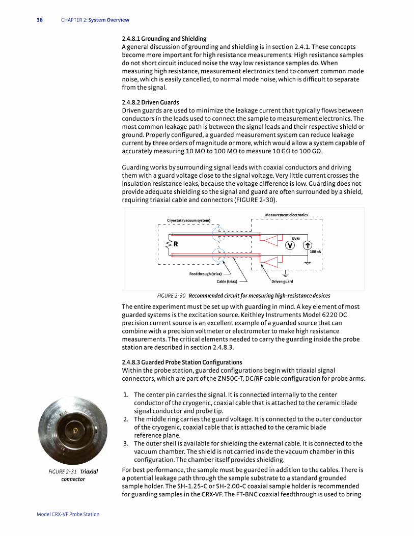
38 CHAPTER 2: System Overview
2.4.8.1 Grounding and ShieldingA general discussion of grounding and shielding is in section 2.4.1. These concepts become more important for high resistance measurements. High resistance samples do not short circuit induced noise the way low resistance samples do. When measuring high resistance, measurement electronics tend to convert common mode noise, which is easily cancelled, to normal mode noise, which is difficult to separate from the signal.
2.4.8.2 Driven GuardsDriven guards are used to minimize the leakage current that typically flows between conductors in the leads used to connect the sample to measurement electronics. The most common leakage path is between the signal leads and their respective shield or ground. Properly configured, a guarded measurement system can reduce leakage current by three orders of magnitude or more, which would allow a system capable of accurately measuring 10 M) to 100 M) to measure 10 G) to 100 G). Guarding works by surrounding signal leads with coaxial conductors and driving them with a guard voltage close to the signal voltage. Very little current crosses the insulation resistance leaks, because the voltage difference is low. Guarding does not provide adequate shielding so the signal and guard are often surrounded by a shield, requiring triaxial cable and connectors (FIGURE 2-30).
The entire experiment must be set up with guarding in mind. A key element of most guarded systems is the excitation source. Keithley Instruments Model 6220 DC precision current source is an excellent example of a guarded source that can combine with a precision voltmeter or electrometer to make high resistance measurements. The critical elements needed to carry the guarding inside the probe station are described in section 2.4.8.3.
2.4.8.3 Guarded Probe Station ConfigurationsWithin the probe station, guarded configurations begin with triaxial signal connectors, which are part of the ZN50C-T, DC/RF cable configuration for probe arms.
1. The center pin carries the signal. It is connected internally to the center
conductor of the cryogenic, coaxial cable that is attached to the ceramic blade signal conductor and probe tip.
2. The middle ring carries the guard voltage. It is connected to the outer conductor of the cryogenic, coaxial cable that is attached to the ceramic blade reference plane.
3. The outer shell is available for shielding the external cable. It is connected to the vacuum chamber. The shield is not carried inside the vacuum chamber in this configuration. The chamber itself provides shielding.
For best performance, the sample must be guarded in addition to the cables. There is a potential leakage path through the sample substrate to a standard grounded sample holder. The SH-1.25-C or SH-2.00-C coaxial sample holder is recommended for guarding samples in the CRX-VF. The FT-BNC coaxial feedthrough is used to bring
FIGURE 2-30 Recommended circuit for measuring high-resistance devices
R
100 nA
V
Feedthrough (triax)
Cable (triax) Driven guard
Measurement electronicsCryostat (vacuum system)
DVM
FIGURE 2-31 Triaxial connector
Model CRX-VF Probe Station
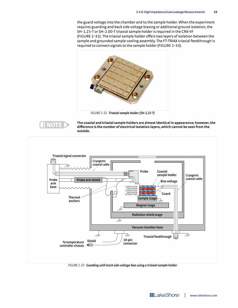
2.4.8 High Impedance/Low Leakage Measurements 39
the guard voltage into the chamber and to the sample holder. When the experiment requires guarding and back side voltage biasing or additional ground isolation, the SH-1.25-T or SH-2.00-T triaxial sample holder is required in the CRX-VF (FIGURE 2-32). The triaxial sample holder offers two layers of isolation between the sample and grounded sample cooling assembly. The FT-TRIAX triaxial feedthrough is required to connect signals to the sample holder (FIGURE 2-33).
The coaxial and triaxial sample holders are almost identical in appearance; however, the difference is the number of electrical isolation layers, which cannot be seen from the outside.
FIGURE 2-32 Triaxial sample holder (SH-1.25-T)
FIGURE 2-33 Guarding with back side voltage bias using a triaxial sample holder
Radiation shield stage
Probe
Sample stage
Cryogenic coaxial cable
Probe armbase
Probe arm shield
To temperature controller chassis
19-pinconnector
Thermalanchors
Shield
Vacuum chamber base
Magnet stage
CONDUCTORINSULATOR
CONDUCTORINSULATOR
CONDUCTOR
Triaxial signal connector
Cryogenic coaxial cable
Coaxialsample holder
Bias voltage
Triaxial feedthrough
Guard
| www.lakeshore.com

40 CHAPTER 2: System Overview
2.4.8.4 Measurement Voltage LimitsThe CRX-VF probe station is specified for signal voltages below 60 VDC and 30 Vrms, referred to as non-hazardous live voltage. The sensor, heater and power supply voltages entering the probe station are all below this voltage. More importantly, testing criteria established for the CE mark assumes there will be no hazardous live voltage operating in the probe station.
Many of the guarded sources, electrometers and other pieces of electronic test equipment used in DC or RF measurements are capable of operating from hundreds of volts to over thousands of volts. The CRX-VF probe station is not specifically designed to ensure operator safety when these voltages are present.
Because Lake Shore has no way to predict how the hazardous live voltages would be configured or operated, it is impossible for us to guarantee safety in the event of improper operation, accidental misconnection or component failure. The CRX-VF does not include the safety interlocks, current limits or earth safety ground system that are necessary for safely working with hazardous live voltages.
2.5 Considerations for Microwave Measurements
Lake Shore offers microwave configurations with ground-signal-ground (GSG) probe geometry optimized for substrates patterned with coplanar waveguide structures. Both signal and ground traces of the microwave structures must be patterned on the top layer of the substrate to facilitate top side probing. Measurements can be performed on both passive and active devices to characterize performance metrics such as S-parameters, noise figure, or load-pull parameters.
Proper use of GSG microwave probes is more complex than of DC/RF probes. Proper probe alignment of the GSG points with respect to the test substrate is required, as is the proper probe planarization with respect to the plane of measurement. Also, calibration may be desired to separate the frequency dependent losses of the measurement setup from the actual device under test.
The remaining sections in this chapter describe details of the microwave probe measurement setup, as well as concepts and techniques that are important for making good microwave measurements in the probe station.
2.5.1 Microwave Cables and Connectors
Microwave cables form transmission lines that carry high frequency signals from the signal connection point outside the vacuum chamber to probe points near the cooled sample. The type and quality of microwave cables and their associated connectors determine the frequency range and overall performance of microwave measurements in the probe station. Properly installed, the cables provide a low loss, broad band electrical path with minimal crosstalk. Also, they need to be compatible with the cryogenic temperatures and vacuum for the CRX-VF.
The geometry of the CRX-VF requires that the cables extend 229 mm (9 in) into the vacuum chamber with a single 90 degree bend. The total length of the microwave cable is approximately 279 mm (11 in). Probe station layout inherently contributes some signal loss. Lake Shore recommends the following for best performance:
1. Calibrate the measurement setup as described in section 2.5.4. 2. Retighten the connectors to manufacturer’s specified torque after repeated
thermal cycling. 3. Keep external cables as short and direct as possible.
Microwave probes must be specified with the same frequency and connector type as the probe cable. TABLE 2-3 summarizes the two microwave probe frequency ranges and associated connectors.
Model CRX-VF Probe Station

2.5.2 Ground Return Path 41
For reference, FIGURE 2-34 to FIGURE 2-35 show plug and socket, head-on views of the three standard types of microwave connectors. Note that all three types look very similar. Side by side, differences in the connectors can be seen primarily in the head-on view in the thickness of outer conductor and spacing between the inner and outer conductor.
The connector types are physically similar and can sometimes, but not always, be interchanged; care should be taken not to damage probes or cables by attempting to mate them improperly.
2.5.2 Ground Return Path
A microwave probe cable consists of a microwave semirigid coaxial cable with connectors permanently mounted on each end. The center conductor is the signal path and extends to the center point on the probe tip. The outer conductor is the reference ground path and extends to the two outer points of the GSG probe tip.
The outer conductor is also electrically connected to the microwave probe body so the measurement reference ground is electrically connected to the sample cooling assembly through the probe mount braids. Keep in mind that this electrical connection may be broken if desired by removing the anchors from the sample stage; however, please note that this will also remove the thermal connection.
Highest rated frequency Connector Mates with
40 GHz K-type (2.92 mm) Standard SMA connectors
67 GHz V-type (1.85 mm) 2.4 mm connectors
TABLE 2-3 Microwave probe frequency ranges and associated connectors
FIGURE 2-34 K-type (2.92 mm) connectors— published mode free to 40 GHz
FIGURE 2-35 V-type (1.85 mm) connectors— published mode free to ~67 GHz
| www.lakeshore.com
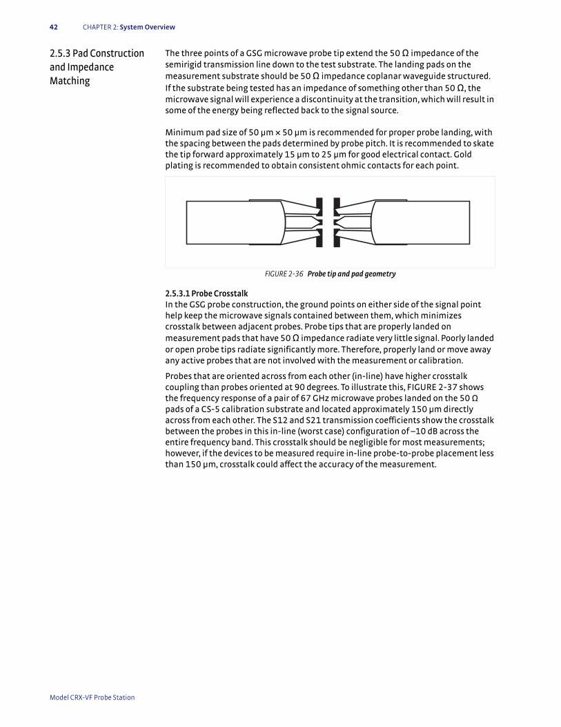
42 CHAPTER 2: System Overview
2.5.3 Pad Construction and Impedance Matching
The three points of a GSG microwave probe tip extend the 50 ) impedance of the semirigid transmission line down to the test substrate. The landing pads on the measurement substrate should be 50 ) impedance coplanar waveguide structured. If the substrate being tested has an impedance of something other than 50 ), the microwave signal will experience a discontinuity at the transition, which will result in some of the energy being reflected back to the signal source.
Minimum pad size of 50 µm × 50 µm is recommended for proper probe landing, with the spacing between the pads determined by probe pitch. It is recommended to skate the tip forward approximately 15 µm to 25 µm for good electrical contact. Gold plating is recommended to obtain consistent ohmic contacts for each point.
2.5.3.1 Probe CrosstalkIn the GSG probe construction, the ground points on either side of the signal point help keep the microwave signals contained between them, which minimizes crosstalk between adjacent probes. Probe tips that are properly landed on measurement pads that have 50 ) impedance radiate very little signal. Poorly landed or open probe tips radiate significantly more. Therefore, properly land or move away any active probes that are not involved with the measurement or calibration.
Probes that are oriented across from each other (in-line) have higher crosstalk coupling than probes oriented at 90 degrees. To illustrate this, FIGURE 2-37 shows the frequency response of a pair of 67 GHz microwave probes landed on the 50 ) pads of a CS-5 calibration substrate and located approximately 150 µm directly across from each other. The S12 and S21 transmission coefficients show the crosstalk between the probes in this in-line (worst case) configuration of –10 dB across the entire frequency band. This crosstalk should be negligible for most measurements; however, if the devices to be measured require in-line probe-to-probe placement less than 150 µm, crosstalk could affect the accuracy of the measurement.
FIGURE 2-36 Probe tip and pad geometry
Model CRX-VF Probe Station

2.5.4 Calibration with the CS-5 Calibration Standard 43
2.5.4 Calibration with the CS-5 Calibration Standard
The following concepts are used with permission from the CS-5 instructions.For the most accurate microwave measurements using a vector network analyzer (VNA), calibration is required to eliminate the frequency dependent losses of the associated connectors, cables, and probe tips. The CS-5 or CS-15 calibration substrate can be used for this purpose. The CS-5 can be used for pitch ranges of 75 to 250 µm and the CS-15 can be used for pitch ranges of 50 to 150 µm.
Standard elements for calibrating a microwave measurement system consist of opens, shorts, matched loads, and throughs. These four elements have electrical characteristics that are very different from one another, so that each one by itself contributes an important part to the calibration.
FIGURE 2-38 shows the response of a pair of 67 GHz probes placed on a 50 ) through test structure on the CS-5 calibration substrate. The measurements were made using a commercial VNA calibration (using mechanical standards) that places the measurement reference plane at the end of the VNA measurement cables that are connected to the input connectors of the 67 GHz probe arms. FIGURE 2-38 shows the frequency dependent characteristics of the probe station with the 67 GHz probes and probe arms. The performance looks very good, with the transmission coefficients S21/S12 remaining above -10 dB and the reflection coefficients S11/S22 remaining below -10 dB over the entire frequency band. The gradual sloping increase in loss (the decrease in S21/S12) as the frequency increases is expected.
FIGURE 2-39 shows the response of a pair of 67 GHz probes placed on a 50 ) through test structure following a SOLT calibration using the CS-5 calibration substrate. This calibration places the VNA measurement reference plane at the end of the probe tips, and thus, removes the losses of the associated cabling and probes from the measurement response of an unknown substrate.
FIGURE 2-37 Frequency response of 67 GHz microwave probes located 150 μm across from each other and landed on the 50 ) pads
of a CS-5 calibration substrate
FIGURE 2-38 S-parameter response of 67 GHz GSG microwave probes
| www.lakeshore.com
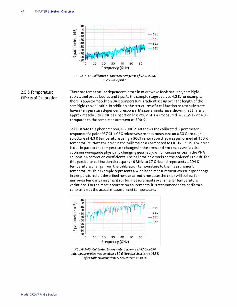
44 CHAPTER 2: System Overview
2.5.5 Temperature Effects of Calibration
There are temperature dependent losses in microwave feedthroughs, semirigid cables, and probe bodies and tips. As the sample stage cools to 4.2 K, for example, there is approximately a 294 K temperature gradient set up over the length of the semirigid coaxial cable. In addition, the structures of a calibration or test substrate have a temperature dependent response. Measurements have shown that there is approximately 1 to 2 dB less insertion loss at 67 GHz as measured in S21/S12 at 4.3 K compared to the same measurement at 300 K.
To illustrate this phenomenon, FIGURE 2-40 shows the calibrated S-parameter response of a pair of 67 GHz GSG microwave probes measured on a 50 ) through structure at 4.3 K temperature using a SOLT calibration that was performed at 300 K temperature. Note the error in the calibration as compared to FIGURE 2-39. The error is due in part to the temperature changes in the arms and probes, as well as the coplanar waveguide physically changing geometry, which causes errors in the VNA calibration correction coefficients. The calibration error is on the order of 1 to 2 dB for this particular calibration that spans 40 MHz to 67 GHz and represents a 294 K temperature change from the calibration temperature to the measurement temperature. This example represents a wide band measurement over a large change in temperature. It is described here as an extreme case; the error will be less for narrower band measurements or for measurements over smaller temperature variations. For the most accurate measurements, it is recommended to perform a calibration at the actual measurement temperature.
FIGURE 2-39 Calibrated S-parameter response of 67 GHz GSG microwave probes
FIGURE 2-40 Calibrated S-parameter response of 67 GHz GSG microwave probes measured on a 50 ) through structure at 4.3 K
after calibration with a CS-5 substrate at 300 K
Model CRX-VF Probe Station
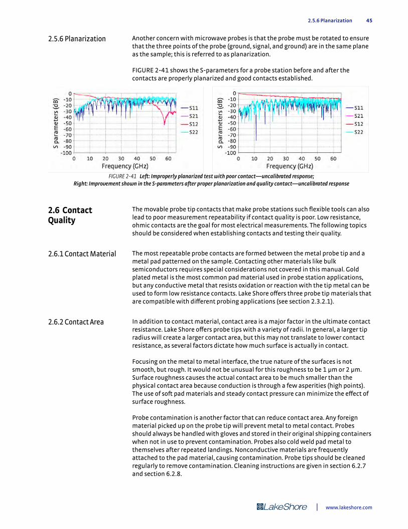
2.5.6 Planarization 45
2.5.6 Planarization Another concern with microwave probes is that the probe must be rotated to ensure that the three points of the probe (ground, signal, and ground) are in the same plane as the sample; this is referred to as planarization.
FIGURE 2-41 shows the S-parameters for a probe station before and after the contacts are properly planarized and good contacts established.
2.6 Contact Quality
The movable probe tip contacts that make probe stations such flexible tools can also lead to poor measurement repeatability if contact quality is poor. Low resistance, ohmic contacts are the goal for most electrical measurements. The following topics should be considered when establishing contacts and testing their quality.
2.6.1 Contact Material The most repeatable probe contacts are formed between the metal probe tip and a metal pad patterned on the sample. Contacting other materials like bulk semiconductors requires special considerations not covered in this manual. Gold plated metal is the most common pad material used in probe station applications, but any conductive metal that resists oxidation or reaction with the tip metal can be used to form low resistance contacts. Lake Shore offers three probe tip materials that are compatible with different probing applications (see section 2.3.2.1).
2.6.2 Contact Area In addition to contact material, contact area is a major factor in the ultimate contact resistance. Lake Shore offers probe tips with a variety of radii. In general, a larger tip radius will create a larger contact area, but this may not translate to lower contact resistance, as several factors dictate how much surface is actually in contact.
Focusing on the metal to metal interface, the true nature of the surfaces is not smooth, but rough. It would not be unusual for this roughness to be 1 µm or 2 µm. Surface roughness causes the actual contact area to be much smaller than the physical contact area because conduction is through a few asperities (high points). The use of soft pad materials and steady contact pressure can minimize the effect of surface roughness.
Probe contamination is another factor that can reduce contact area. Any foreign material picked up on the probe tip will prevent metal to metal contact. Probes should always be handled with gloves and stored in their original shipping containers when not in use to prevent contamination. Probes also cold weld pad metal to themselves after repeated landings. Nonconductive materials are frequently attached to the pad material, causing contamination. Probe tips should be cleaned regularly to remove contamination. Cleaning instructions are given in section 6.2.7 and section 6.2.8.
FIGURE 2-41 Left: Improperly planarized test with poor contact—uncalibrated response; Right: Improvement shown in the S-parameters after proper planarization and quality contact—uncalibrated response
| www.lakeshore.com

46 CHAPTER 2: System Overview
2.6.3 Oxidation Oxidation is probably the biggest source of poor contact resistance in a well maintained probe station. Oxidation builds up on the probe and pad metals over time to form an electrically insulating layer that prevents metal to metal contact. The light oxidation that forms between routine uses can normally be wiped clean when the probe is landed. If the probe or pad is allowed to form a thick oxide film (tarnish), more aggressive action is necessary. Pre-cleaning or over-travel of the probe tip (scratching) may be required to create forces large enough to break the film. The larger, softer tips that help increase surface area may not be as good at scratching through oxidation; therefore, a compromise is often necessary. Controlled electrical current can also be used to break through any remaining insulating barrier.
2.6.4 Four-Lead Measurement
A four-lead measurement technique is frequently used during resistance measurements to eliminate the effect of unwanted contact and lead resistance. In this technique, the two excitation current leads are separated from the two voltage measurement leads all the way down to the probe tips. A reasonable amount of contact resistance and small changes in contact resistance will not appear in the voltage measurement because there is no current flowing through the voltage contact. However, this technique will not overcome contacts that have too much resistance or are non-ohmic.
2.6.5 Ohmic versus Non-ohmic Contacts
Ohmic contacts result from a good interface between two conductive surfaces. They are called ohmic because they exhibit a linear relationship between current and voltage, like a resistor. Non-ohmic contacts are typically formed when oxides or other contamination is present between the conductive surfaces. They exhibit a non-linear relationship between current and voltage more closely resembling a diode. This is undesirable because signals resulting from the contact cannot easily be subtracted from the desired signal of the sample.
2.6.6 Measuring Contact Quality
Measuring contact quality is always recommended for critical measurements to make sure the contact resistance is low and the contact is ohmic. Both contact resistance and ohmic behavior can be checked at the same time. The most common DC technique is to excite two probe contacts at a time with different positive and negative currents and plot the measured voltage (IV curve). A linear curve with a low slope indicates a good contact. Non-linearity in the curve indicates a non-ohmic contact. If the test cannot be performed on the actual device, probing technique can be verified by landing two probes on one sample pad and making an IV curve prior to probing the device.
In the case of a microwave measurement, contact resistance increases the series resistance of the microwave circuit. However, the film between the probe and measurement pad can form a capacitor. This capacitance will change the S-parameters of the device as measured by a network analyzer. A level response on the network analyzer is typically the best measure of contact quality.
2.6.7 Lab Protocol Lake Shore recommends developing a lab protocol to ensure consistent contacts. The protocol should include probe handling, routine cleaning, landing probes and measuring contacts. The probe landing instructions given in section 4.7.2 describe the action of skating the probe tip on the sample pad. The amount of skate is one of the most important parts of the protocol. More skate provides more wiping to clean away oxidation and more pressure to increase actual contact area. Too much skate will damage the probe tip.
Model CRX-VF Probe Station
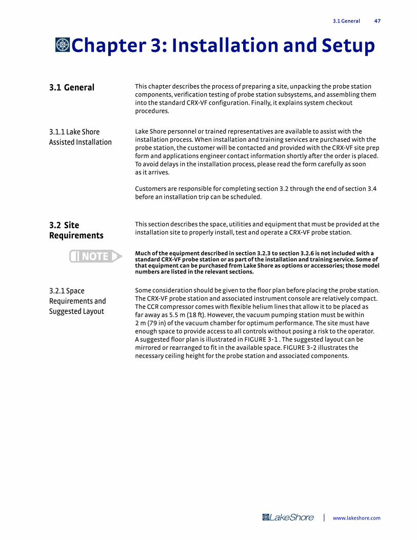
3.1 General 47
Chapter 3: Installation and Setup
3.1 General This chapter describes the process of preparing a site, unpacking the probe station components, verification testing of probe station subsystems, and assembling them into the standard CRX-VF configuration. Finally, it explains system checkout procedures.
3.1.1 Lake Shore Assisted Installation
Lake Shore personnel or trained representatives are available to assist with the installation process. When installation and training services are purchased with the probe station, the customer will be contacted and provided with the CRX-VF site prep form and applications engineer contact information shortly after the order is placed. To avoid delays in the installation process, please read the form carefully as soon as it arrives.
Customers are responsible for completing section 3.2 through the end of section 3.4 before an installation trip can be scheduled.
3.2 Site Requirements
This section describes the space, utilities and equipment that must be provided at the installation site to properly install, test and operate a CRX-VF probe station.
Much of the equipment described in section 3.2.3 to section 3.2.6 is not included with a standard CRX-VF probe station or as part of the installation and training service. Some of that equipment can be purchased from Lake Shore as options or accessories; those model numbers are listed in the relevant sections.
3.2.1 Space Requirements and Suggested Layout
Some consideration should be given to the floor plan before placing the probe station. The CRX-VF probe station and associated instrument console are relatively compact. The CCR compressor comes with flexible helium lines that allow it to be placed as far away as 5.5 m (18 ft). However, the vacuum pumping station must be within 2 m (79 in) of the vacuum chamber for optimum performance. The site must have enough space to provide access to all controls without posing a risk to the operator. A suggested floor plan is illustrated in FIGURE 3-1 . The suggested layout can be mirrored or rearranged to fit in the available space. FIGURE 3-2 illustrates the necessary ceiling height for the probe station and associated components.
| www.lakeshore.com
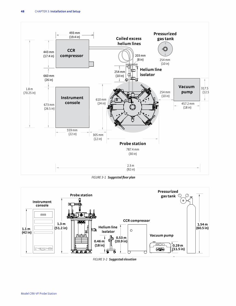
48 CHAPTER 3: Installation and Setup
FIGURE 3-1 Suggested floor plan
673 mm (26.5 in)
559 mm (22 in)
317.5 (12.5
457.2 mm (18 in)
305 mm(12 in)
610 mm (24 in)
787.4 mm (30 in)
254 mm (10 in)
1.8 m (70.25 in)
2.3 m (92 in)
Instrumentconsole
Probe station
Vacuum pump
493 mm(19.4 in)
443 mm(17.4 in)
CCR compressor
Coiled excess helium lines
Helium lineisolator
254 mm (10 in)
Pressurized gas tank
660 mm(26 in)
254 mm(10 in)
203 mm(8 in)
FIGURE 3-2 Suggested elevation
Screen
Instrumentconsole
Vacuum pump
1.1 m (42 in)
0.53 m (20.9 in)
1.3 m(51.2 in)
0.29 m (11.5 in)
Probe station
CCR compressor
0.46 m (18 in)
1.54 m (60.5 in)
Pressurized gas tank
Helium line isolator
Model CRX-VF Probe Station
3.2.2 Environmental Requirements and Concerns 49
3.2.2 Environmental Requirements and Concerns
There are several environmental considerations that may affect probe station operation, probe measurements or the safety of the user. The following sections discuss vibration considerations, electrical noise, ventilation, and safety considerations.
3.2.2.1 VibrationPlace the probe station away from major sources of vibration to avoid problems when landing probes and to avoid electrically noisy probe contacts. In order to meet the published vibration specification, the station must be placed on a stable concrete floor, preferably on the lowest floor of the building, and away from elevators, large motors, or moving equipment.
The CRX-VF design incorporates standard features to isolate the sample stage from the vibration of the reciprocating CCR. There are also standard features to help reduce the impact of environmental vibration. However, the probe station turbo pumping system can be a source of vibration. The vacuum pump is often turned off when the sample cooling assembly is cooled to below 77 K. Additional vibration isolation may be needed if working outside of that range. The Lake Shore PS-PLVI-40 pump line vibration isolator or equivalent is recommended for reducing vacuum pump vibration.
3.2.2.2 Electrical NoisePlace the probe station away from major sources of electrical noise to avoid interference with probe measurements. Common electrical noise sources in buildings are power distribution panels, high capacity power lines, communications distribution centers and RF (radio) transmitters.
Line power quality can also impact electrical measurements performed in the probe station. When possible, avoid long or indirect power routing, circuits that are shared with motors or other noisy loads, unbalanced, overloaded, and poorly grounded circuits. When poor quality power circuits are unavoidable, an isolation transformer for measurement instruments may be required to achieve optimum performance.
3.2.2.3 VentilationPlace the probe station in a well ventilated area to avoid the risk of asphyxiation from helium gas in the event that it is accidentally released from the CCR compressor.
Helium gas displaces oxygen in its vicinity, presenting an asphyxiation hazard. There is a risk of oxygen deficiency if the oxygen level falls below 19.5%.
3.2.2.4 Magnetic FieldsThe CRX-VF is capable of generating a strong magnetic field. This field can be dangerous to people with some types of medical implants. The system should be located away from hallways or other frequently traveled areas. Appropriate barriers and signs should be placed near the probe station to warn of high magnetic fields.
The 5 gauss line extends 0.6 m radially from outside of the vacuum chamber, 1 m above the top of the vacuum chamber, and 0.1 m to 0.2 m below the floor where the CRX-VF is positioned.
Ensure that no one with a pacemaker, magnetic implant, or neurostimulator comes near the probe station. The superconducting magnet is unshielded and produces a 2.5 T magnetic field that can disrupt medical implants. Failure to comply could result in injury or death.
The superconducting magnets are unshielded and produce a 2.5 T magnetic field that can erase magnetic media, damage watches and affect other instruments.
| www.lakeshore.com
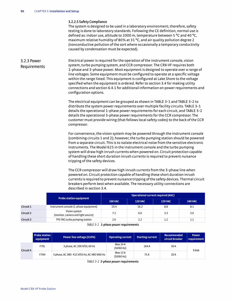
50 CHAPTER 3: Installation and Setup
3.2.2.5 Safety ComplianceThe system is designed to be used in a laboratory environment; therefore, safety testing is done to laboratory standards. Following the CE definition, normal use is defined as: indoor use, altitude to 2000 m, temperature between 5 °C and 40 °C, maximum relative humidity of 80% at 31 °C, and air quality pollution degree 2 (nonconductive pollution of the sort where occasionally a temporary conductivity caused by condensation must be expected).
3.2.3 Power Requirements
Electrical power is required for the operation of the instrument console, vision system, turbo pumping system, and CCR compressor. The CRX-VF requires both 1-phase and 3-phase power. Most equipment is designed to operate over a range of line voltages. Some equipment must be configured to operate at a specific voltage within the range listed. This equipment is configured at Lake Shore to the voltage specified when the equipment is ordered. Refer to section 3.4 for making utility connections and section 6.4.1 for additional information on power requirements and configuration options.
The electrical equipment can be grouped as shown in TABLE 3-1 and TABLE 3-2 to distribute the system power requirements over multiple facility circuits. TABLE 3-1 details the operational 1-phase power requirements for each circuit, and TABLE 3-2 details the operational 3-phase power requirements for the CCR compressor. The customer must provide wiring (that follows local safety codes) to the back of the CCR compressor.
For convenience, the vision system may be powered through the instrument console (combining circuits 1 and 2); however, the turbo pumping station should be powered from a separate circuit. This is to isolate electrical noise from the sensitive electronic instruments. The Model 625 in the instrument console and the turbo pumping system will draw high inrush currents when powered on. Circuit protection capable of handling these short duration inrush currents is required to prevent nuisance tripping of the safety devices.
The CCR compressor will draw high inrush currents from the 3-phase line when powered on. Circuit protection capable of handling these short duration inrush currents is required to prevent nuisance tripping of the safety devices. Thermal circuit breakers perform best when available. The necessary utility connections are described in section 3.4.
Probe station equipmentOperational current required (AAC)
100 VAC 120 VAC 220 VAC 240 VAC
Circuit 1 Instrument console (1-phase equipment) 19.4 16.2 8.8 8.1
Circuit 2Vision system
(monitor, camera and light source)7.2 6.0 3.3 3.0
Circuit 3 TPS FRG turbo pumping station 2.6 2.2 1.2 1.1
TABLE 3-1 1-phase power requirements
Probe station equipment
Power line voltage (±10%) Operating current Starting currentRecommended circuit breaker
Power requirement
Circuit 4F70L 3 phase, AC 200 V/50, 60 Hz
Max 24 A (50/60 Hz)
164 A 30 A
9 kVA
F70H 3 phase, AC 380- 415 V/50 Hz; AC 480 V/60 HzMax 13 A
(50/60 Hz)75 A 20 A
TABLE 3-2 3-phase power requirements
Model CRX-VF Probe Station
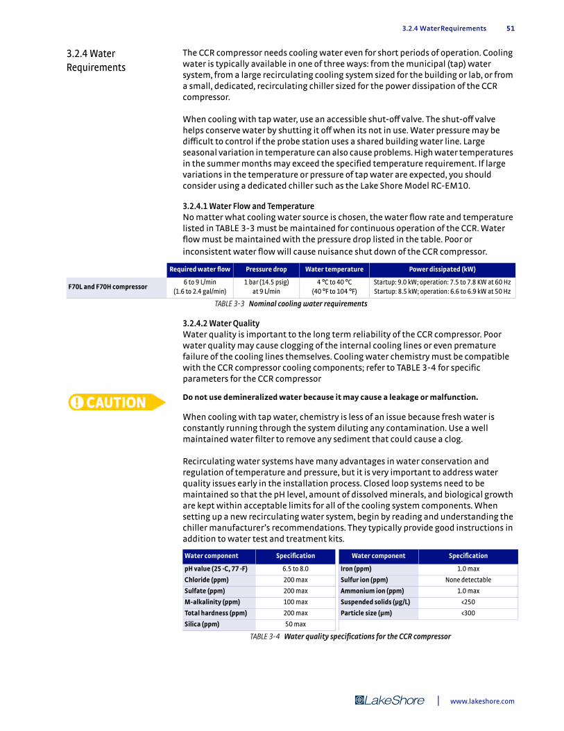
3.2.4 Water Requirements 51
3.2.4 Water Requirements
The CCR compressor needs cooling water even for short periods of operation. Cooling water is typically available in one of three ways: from the municipal (tap) water system, from a large recirculating cooling system sized for the building or lab, or from a small, dedicated, recirculating chiller sized for the power dissipation of the CCR compressor.
When cooling with tap water, use an accessible shut-off valve. The shut-off valve helps conserve water by shutting it off when its not in use. Water pressure may be difficult to control if the probe station uses a shared building water line. Large seasonal variation in temperature can also cause problems. High water temperatures in the summer months may exceed the specified temperature requirement. If large variations in the temperature or pressure of tap water are expected, you should consider using a dedicated chiller such as the Lake Shore Model RC-EM10.
3.2.4.1 Water Flow and TemperatureNo matter what cooling water source is chosen, the water flow rate and temperature listed in TABLE 3-3 must be maintained for continuous operation of the CCR. Water flow must be maintained with the pressure drop listed in the table. Poor or inconsistent water flow will cause nuisance shut down of the CCR compressor.
3.2.4.2 Water QualityWater quality is important to the long term reliability of the CCR compressor. Poor water quality may cause clogging of the internal cooling lines or even premature failure of the cooling lines themselves. Cooling water chemistry must be compatible with the CCR compressor cooling components; refer to TABLE 3-4 for specific parameters for the CCR compressor
Do not use demineralized water because it may cause a leakage or malfunction.
When cooling with tap water, chemistry is less of an issue because fresh water is constantly running through the system diluting any contamination. Use a well maintained water filter to remove any sediment that could cause a clog. Recirculating water systems have many advantages in water conservation and regulation of temperature and pressure, but it is very important to address water quality issues early in the installation process. Closed loop systems need to be maintained so that the pH level, amount of dissolved minerals, and biological growth are kept within acceptable limits for all of the cooling system components. When setting up a new recirculating water system, begin by reading and understanding the chiller manufacturer’s recommendations. They typically provide good instructions in addition to water test and treatment kits.
Required water flow Pressure drop Water temperature Power dissipated (kW)
F70L and F70H compressor6 to 9 L/min
(1.6 to 2.4 gal/min)1 bar (14.5 psig)
at 9 L/min4 °C to 40 °C
(40 °F to 104 °F)Startup: 9.0 kW; operation: 7.5 to 7.8 KW at 60 HzStartup: 8.5 kW; operation: 6.6 to 6.9 kW at 50 Hz
TABLE 3-3 Nominal cooling water requirements
Water component Specification Water component Specification
pH value (25 ·C, 77 ·F) 6.5 to 8.0 Iron (ppm) 1.0 max
Chloride (ppm) 200 max Sulfur ion (ppm) None detectable
Sulfate (ppm) 200 max Ammonium ion (ppm) 1.0 max
M-alkalinity (ppm) 100 max Suspended solids (μg/L) <250
Total hardness (ppm) 200 max Particle size (μm) <300
Silica (ppm) 50 max
TABLE 3-4 Water quality specifications for the CCR compressor
| www.lakeshore.com

52 CHAPTER 3: Installation and Setup
3.2.4.3 Water Routing and ConnectionsThe CCR compressor water inlet and outlet are NPT ½ in (10 mm), Swagelok® MNPT ½ in fittings are included with the compressor.
You are responsible for providing the necessary lengths of tubing and connections to your cooling water system.
To ensure safe operation, the cooling water system must have a water filter, flow meter, safety shutoff, and pressure gauge (not provided). Refer to section 3.4.3 for setup information. Use a flow meter on the outlet of the CCR compressor, and a cooling water system that has a filter, safety shutoff, and pressure gauge to monitor coolant water flow.
3.2.5 Vacuum Requirements
The probe station vacuum chamber provides thermal insulation for the internal sample cooling assembly as it cryogenically cools the sample being tested. It also prevents condensation or other contamination from affecting the sample.
High quality vacuum equipment is necessary for good cooling performance and for keeping the sample clean. You must provide a vacuum pumping system including appropriate gauges and vacuum lines for the CRX-VF. It must have the ability to attain at least <10-3 Torr in the probe station while at room temperature. A vacuum isolation valve with an NW 40 flange is included on the CCR vacuum shroud. Lake Shore offers the TPS FRG for evacuating the chamber. Components and specifications for these options are in section 2.3.7. You should use these specifications as a guideline if you purchase the pumping system separately.
If you do not purchase the turbo pumping system option with the probe station, you will need to provide a calibrated vacuum gauge during installation to verify vacuum levels.
3.2.6 Gas Requirements During system warm up and sample change operations, it can be beneficial to purge the vacuum chamber with inert gas. A purge valve with a p in NPT connection is provided on the vacuum chamber for this purpose. Dry argon or nitrogen gas is recommended for most purge operations, but other inert gasses can be used. Helium is not recommended because it is difficult to pump out when re-evacuating the system.
For purging the vacuum chamber you will need a gas cylinder or other source of dry, high purity gas, an independent low pressure regulator capable of providing steady pressure between 6.9 kPa to 13.8 kPa (1 to 2 psi), and a gas line and fittings. Lake Shore does not offer these components as accessories.
Gas cylinders must be anchored properly before use. Tipping cylinders can cause serious injury or death.
Model CRX-VF Probe Station

3.3 Unpacking the Probe Station 53
3.3 Unpacking the Probe Station
The following sections describe the unpacking of each component shipped with the probe station. Please report any shortages or potential shipping damage prior to arranging Lake Shore assisted installation or within five days of shipment. It is important that you read and understand this section thoroughly before starting the process. Clear enough space to complete all steps safely.
3.3.1 Shipping Containers
The standard components of the Model CRX-VF will be shipped in two crates and a palletized box. One crate contains the probe station and helium line isolator; the second crate contains the instrument console. The palletized box contains the CCR compressor. Other CCR components and most of the accessories and options configured with the CRX-VF are contained in the crate with the instrument console. TABLE 3-5 lists approximate size and weight of the standard shipping containers. The weight of the crates varies depending on probe station configurations and options ordered.
3.3.2 Inspecting for Shipping Damage
Upon receipt of the system, check for signs of rough handling, such as damage to the shipping container or broken shock indicators attached to the outside and inside of the shipping container. If any physical damage is suspected, do not open containers before photographing the damage and informing the shipping agents and Lake Shore or your local representative. Contact information for Lake Shore service is given in section 6.5. Shipping containers and shipping materials should be kept in the event you would need to return your probe station.
Size (l × w × h) Weight
CRX-VF probe station crate* 1.22 m (48 in) × 0.91 m (36 in) × 1.22 m (48 in) 499 kg (1100 lb) to 590 kg (1300 lb)
Instrument console and accessories crate*
1.22 m (48 in) × 0.91 m (36 in) × 1.22 m (48 in) 227 kg (500 lb) to 317 kg (700 lb)
CCR compressor box 0.56 m (22 in) × 0.79 m (31 in) × 0.86 m (34 in) 143 kg (315 lb)
*Weight may vary depending on configuration and options ordered
TABLE 3-5 Shipping container size and weight
FIGURE 3-3 If you suspect damage, take a photo of the packed shipment, specifically
damaged areas; Left: Probe station and helium line isolator; Right: Console and accessories
| www.lakeshore.com

54 CHAPTER 3: Installation and Setup
3.3.3 Required Tools The following tools are required to unpack the crated probe station and are not included with the shipment.
D Clean safe work spaceD Lifting equipment D Box cutter (knife)D Phillips head screw driver (battery powered if available)D Adjustable wrenches or a wrench set with up to 3/4 in (19 mm)D Small diagonal wire cuttersD Small levelD Linear scale (ruler or tape measure)
3.3.4 Moving and Lifting the Probe Station
If space and equipment is available, the loaded shipping crates should be moved to the installation site intact. They can be moved easily with a pallate jack while the contents remain protected.
Use lifting equipment throughout this procedure. The probe station weighs over 362 kg (800 lb), has a high center of gravity, and is uneven in its weight distribution. Failure to comply may result in injury or death.
If the CRX-VF must be moved after the initial installation, use section 3.6.1 and FIGURE 3-11 as a guide to reinstall the red spacing washers to lock the inner CCR stand to the outer stand.
Before lifting or moving the probe station, the outer stand and inner CCR stand must be locked together with the locking bolts and red spacing washers shown in FIGURE 3-11. Failure to secure these together before lifting will result in permanent damage to the probe station.
FIGURE 3-4 Use lifting equipment if the probe station must be moved after it is uncrated
Model CRX-VF Probe Station
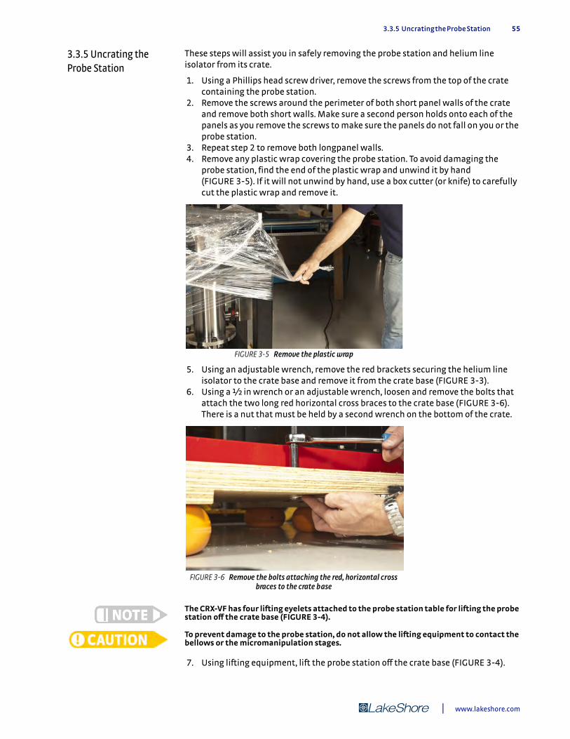
3.3.5 Uncrating the Probe Station 55
3.3.5 Uncrating the Probe Station
These steps will assist you in safely removing the probe station and helium line isolator from its crate.
1. Using a Phillips head screw driver, remove the screws from the top of the crate containing the probe station.
2. Remove the screws around the perimeter of both short panel walls of the crate and remove both short walls. Make sure a second person holds onto each of the panels as you remove the screws to make sure the panels do not fall on you or the probe station.
3. Repeat step 2 to remove both longpanel walls. 4. Remove any plastic wrap covering the probe station. To avoid damaging the
probe station, find the end of the plastic wrap and unwind it by hand (FIGURE 3-5). If it will not unwind by hand, use a box cutter (or knife) to carefully cut the plastic wrap and remove it.
5. Using an adjustable wrench, remove the red brackets securing the helium line isolator to the crate base and remove it from the crate base (FIGURE 3-3).
6. Using a q in wrench or an adjustable wrench, loosen and remove the bolts that attach the two long red horizontal cross braces to the crate base (FIGURE 3-6). There is a nut that must be held by a second wrench on the bottom of the crate.
The CRX-VF has four lifting eyelets attached to the probe station table for lifting the probe station off the crate base (FIGURE 3-4).
To prevent damage to the probe station, do not allow the lifting equipment to contact the bellows or the micromanipulation stages.
7. Using lifting equipment, lift the probe station off the crate base (FIGURE 3-4).
FIGURE 3-5 Remove the plastic wrap
FIGURE 3-6 Remove the bolts attaching the red, horizontal cross braces to the crate base
| www.lakeshore.com
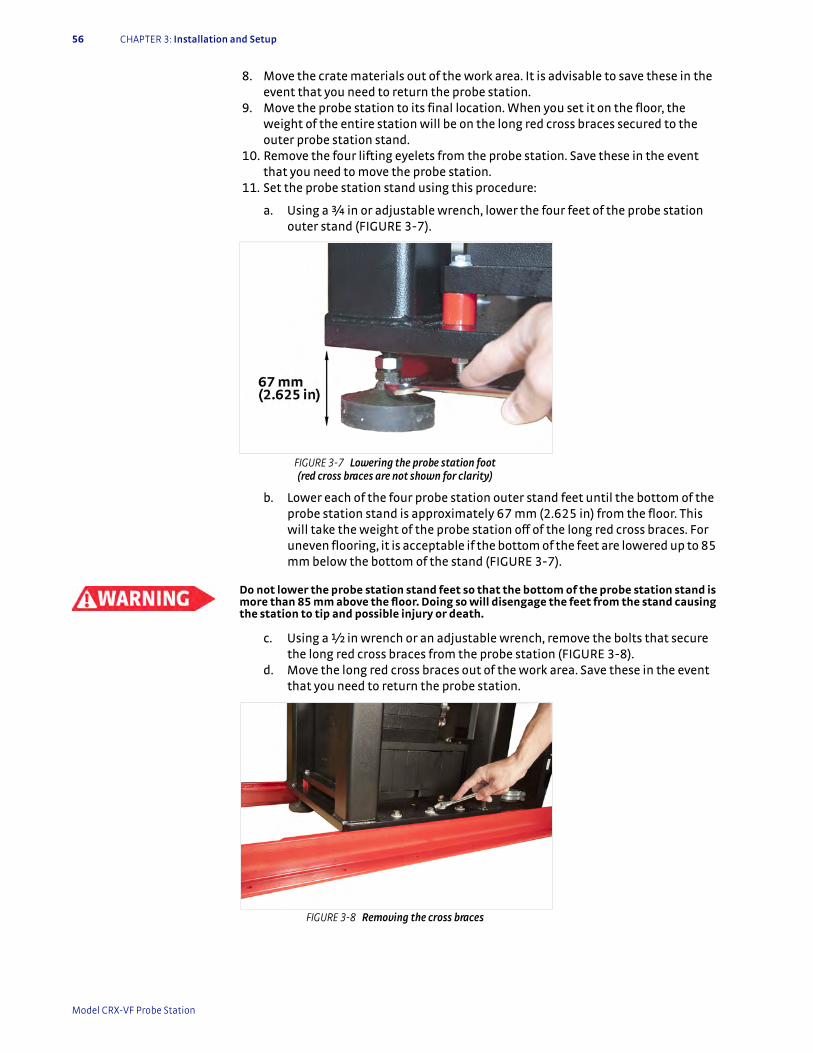
56 CHAPTER 3: Installation and Setup
8. Move the crate materials out of the work area. It is advisable to save these in the event that you need to return the probe station.
9. Move the probe station to its final location. When you set it on the floor, the weight of the entire station will be on the long red cross braces secured to the outer probe station stand.
10. Remove the four lifting eyelets from the probe station. Save these in the event that you need to move the probe station.
11. Set the probe station stand using this procedure:
a. Using a ¾ in or adjustable wrench, lower the four feet of the probe station outer stand (FIGURE 3-7).
b. Lower each of the four probe station outer stand feet until the bottom of the probe station stand is approximately 67 mm (2.625 in) from the floor. This will take the weight of the probe station off of the long red cross braces. For uneven flooring, it is acceptable if the bottom of the feet are lowered up to 85 mm below the bottom of the stand (FIGURE 3-7).
Do not lower the probe station stand feet so that the bottom of the probe station stand is more than 85 mm above the floor. Doing so will disengage the feet from the stand causing the station to tip and possible injury or death.
c. Using a q in wrench or an adjustable wrench, remove the bolts that secure the long red cross braces from the probe station (FIGURE 3-8).
d. Move the long red cross braces out of the work area. Save these in the event that you need to return the probe station.
FIGURE 3-7 Lowering the probe station foot (red cross braces are not shown for clarity)
FIGURE 3-8 Removing the cross braces
Model CRX-VF Probe Station
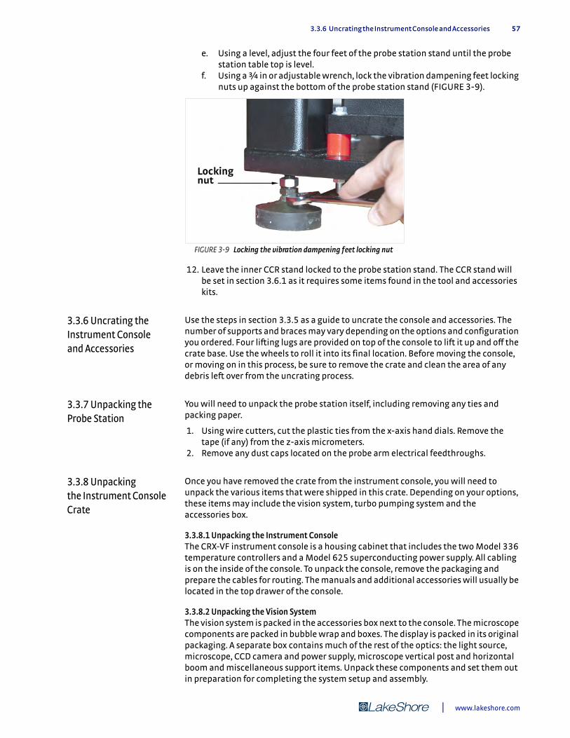
3.3.6 Uncrating the Instrument Console and Accessories 57
e. Using a level, adjust the four feet of the probe station stand until the probe station table top is level.
f. Using a ¾ in or adjustable wrench, lock the vibration dampening feet locking nuts up against the bottom of the probe station stand (FIGURE 3-9).
12. Leave the inner CCR stand locked to the probe station stand. The CCR stand will be set in section 3.6.1 as it requires some items found in the tool and accessories kits.
3.3.6 Uncrating the Instrument Console and Accessories
Use the steps in section 3.3.5 as a guide to uncrate the console and accessories. The number of supports and braces may vary depending on the options and configuration you ordered. Four lifting lugs are provided on top of the console to lift it up and off the crate base. Use the wheels to roll it into its final location. Before moving the console, or moving on in this process, be sure to remove the crate and clean the area of any debris left over from the uncrating process.
3.3.7 Unpacking the Probe Station
You will need to unpack the probe station itself, including removing any ties and packing paper.
1. Using wire cutters, cut the plastic ties from the x-axis hand dials. Remove the tape (if any) from the z-axis micrometers.
2. Remove any dust caps located on the probe arm electrical feedthroughs.
3.3.8 Unpacking the Instrument Console Crate
Once you have removed the crate from the instrument console, you will need to unpack the various items that were shipped in this crate. Depending on your options, these items may include the vision system, turbo pumping system and the accessories box.
3.3.8.1 Unpacking the Instrument ConsoleThe CRX-VF instrument console is a housing cabinet that includes the two Model 336 temperature controllers and a Model 625 superconducting power supply. All cabling is on the inside of the console. To unpack the console, remove the packaging and prepare the cables for routing. The manuals and additional accessories will usually be located in the top drawer of the console.
3.3.8.2 Unpacking the Vision SystemThe vision system is packed in the accessories box next to the console. The microscope components are packed in bubble wrap and boxes. The display is packed in its original packaging. A separate box contains much of the rest of the optics: the light source, microscope, CCD camera and power supply, microscope vertical post and horizontal boom and miscellaneous support items. Unpack these components and set them out in preparation for completing the system setup and assembly.
FIGURE 3-9 Locking the vibration dampening feet locking nut
| www.lakeshore.com
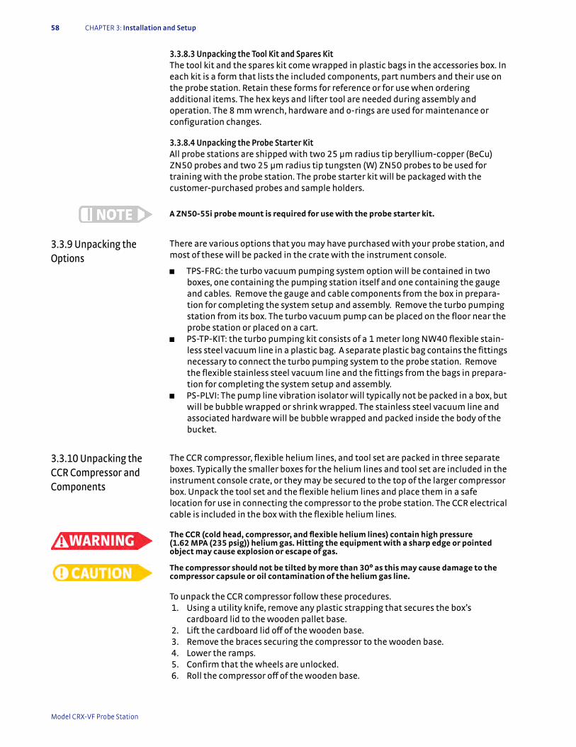
58 CHAPTER 3: Installation and Setup
3.3.8.3 Unpacking the Tool Kit and Spares KitThe tool kit and the spares kit come wrapped in plastic bags in the accessories box. In each kit is a form that lists the included components, part numbers and their use on the probe station. Retain these forms for reference or for use when ordering additional items. The hex keys and lifter tool are needed during assembly and operation. The 8 mm wrench, hardware and o-rings are used for maintenance or configuration changes.
3.3.8.4 Unpacking the Probe Starter KitAll probe stations are shipped with two 25 µm radius tip beryllium-copper (BeCu) ZN50 probes and two 25 µm radius tip tungsten (W) ZN50 probes to be used for training with the probe station. The probe starter kit will be packaged with the customer-purchased probes and sample holders.
A ZN50-55i probe mount is required for use with the probe starter kit.
3.3.9 Unpacking the Options
There are various options that you may have purchased with your probe station, and most of these will be packed in the crate with the instrument console.
D TPS-FRG: the turbo vacuum pumping system option will be contained in two boxes, one containing the pumping station itself and one containing the gauge and cables. Remove the gauge and cable components from the box in prepara-tion for completing the system setup and assembly. Remove the turbo pumping station from its box. The turbo vacuum pump can be placed on the floor near the probe station or placed on a cart.
D PS-TP-KIT: the turbo pumping kit consists of a 1 meter long NW40 flexible stain-less steel vacuum line in a plastic bag. A separate plastic bag contains the fittings necessary to connect the turbo pumping system to the probe station. Remove the flexible stainless steel vacuum line and the fittings from the bags in prepara-tion for completing the system setup and assembly.
D PS-PLVI: The pump line vibration isolator will typically not be packed in a box, but will be bubble wrapped or shrink wrapped. The stainless steel vacuum line and associated hardware will be bubble wrapped and packed inside the body of the bucket.
3.3.10 Unpacking the CCR Compressor and Components
The CCR compressor, flexible helium lines, and tool set are packed in three separate boxes. Typically the smaller boxes for the helium lines and tool set are included in the instrument console crate, or they may be secured to the top of the larger compressor box. Unpack the tool set and the flexible helium lines and place them in a safe location for use in connecting the compressor to the probe station. The CCR electrical cable is included in the box with the flexible helium lines.
The CCR (cold head, compressor, and flexible helium lines) contain high pressure (1.62 MPA (235 psig)) helium gas. Hitting the equipment with a sharp edge or pointed object may cause explosion or escape of gas.
The compressor should not be tilted by more than 30° as this may cause damage to the compressor capsule or oil contamination of the helium gas line.
To unpack the CCR compressor follow these procedures. 1. Using a utility knife, remove any plastic strapping that secures the box’s
cardboard lid to the wooden pallet base. 2. Lift the cardboard lid off of the wooden base. 3. Remove the braces securing the compressor to the wooden base. 4. Lower the ramps. 5. Confirm that the wheels are unlocked. 6. Roll the compressor off of the wooden base.
Model CRX-VF Probe Station
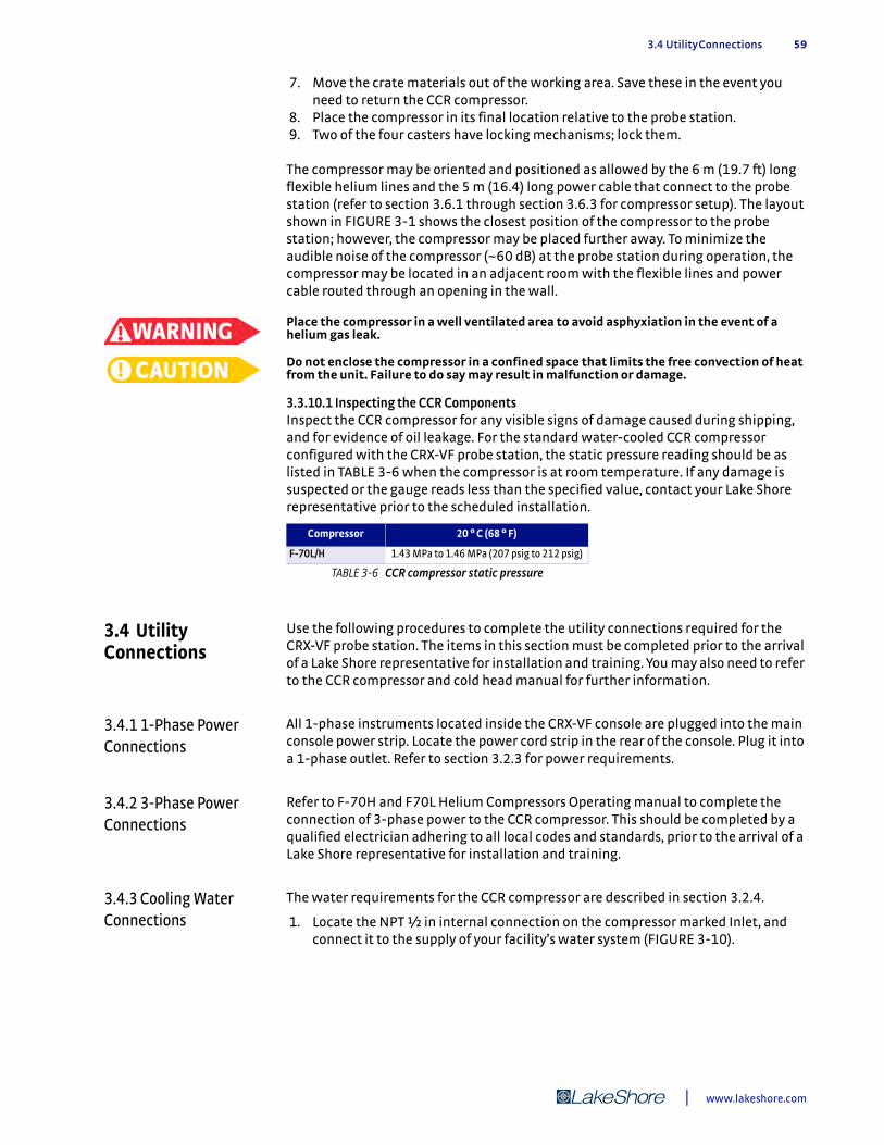
3.4 Utility Connections 59
7. Move the crate materials out of the working area. Save these in the event you need to return the CCR compressor.
8. Place the compressor in its final location relative to the probe station. 9. Two of the four casters have locking mechanisms; lock them.
The compressor may be oriented and positioned as allowed by the 6 m (19.7 ft) long flexible helium lines and the 5 m (16.4) long power cable that connect to the probe station (refer to section 3.6.1 through section 3.6.3 for compressor setup). The layout shown in FIGURE 3-1 shows the closest position of the compressor to the probe station; however, the compressor may be placed further away. To minimize the audible noise of the compressor (~60 dB) at the probe station during operation, the compressor may be located in an adjacent room with the flexible lines and power cable routed through an opening in the wall.
Place the compressor in a well ventilated area to avoid asphyxiation in the event of a helium gas leak.
Do not enclose the compressor in a confined space that limits the free convection of heat from the unit. Failure to do say may result in malfunction or damage.
3.3.10.1 Inspecting the CCR ComponentsInspect the CCR compressor for any visible signs of damage caused during shipping, and for evidence of oil leakage. For the standard water-cooled CCR compressor configured with the CRX-VF probe station, the static pressure reading should be as listed in TABLE 3-6 when the compressor is at room temperature. If any damage is suspected or the gauge reads less than the specified value, contact your Lake Shore representative prior to the scheduled installation.
3.4 Utility Connections
Use the following procedures to complete the utility connections required for the CRX-VF probe station. The items in this section must be completed prior to the arrival of a Lake Shore representative for installation and training. You may also need to refer to the CCR compressor and cold head manual for further information.
3.4.1 1-Phase Power Connections
All 1-phase instruments located inside the CRX-VF console are plugged into the main console power strip. Locate the power cord strip in the rear of the console. Plug it into a 1-phase outlet. Refer to section 3.2.3 for power requirements.
3.4.2 3-Phase Power Connections
Refer to F-70H and F70L Helium Compressors Operating manual to complete the connection of 3-phase power to the CCR compressor. This should be completed by a qualified electrician adhering to all local codes and standards, prior to the arrival of a Lake Shore representative for installation and training.
3.4.3 Cooling Water Connections
The water requirements for the CCR compressor are described in section 3.2.4.
1. Locate the NPT ½ in internal connection on the compressor marked Inlet, and connect it to the supply of your facility’s water system (FIGURE 3-10).
Compressor 20 ° C (68 ° F)
F-70L/H 1.43 MPa to 1.46 MPa (207 psig to 212 psig)
TABLE 3-6 CCR compressor static pressure
| www.lakeshore.com
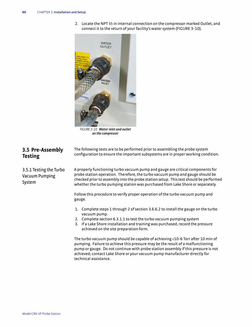
60 CHAPTER 3: Installation and Setup
2. Locate the NPT ½ in internal connection on the compressor marked Outlet, and connect it to the return of your facility’s water system (FIGURE 3-10).
3.5 Pre-Assembly Testing
The following tests are to be performed prior to assembling the probe system configuration to ensure the important subsystems are in proper working condition.
3.5.1 Testing the Turbo Vacuum Pumping System
A properly functioning turbo vacuum pump and gauge are critical components for probe station operation. Therefore, the turbo vacuum pump and gauge should be checked prior to assembly into the probe station setup. This test should be performed whether the turbo pumping station was purchased from Lake Shore or separately.
Follow this procedure to verify proper operation of the turbo vacuum pump and gauge.
1. Complete steps 1 through 2 of section 3.6.6.2 to install the gauge on the turbo vacuum pump.
2. Complete section 6.3.1.1 to test the turbo vacuum pumping system 3. If a Lake Shore installation and training was purchased, record the pressure
achieved on the site preparation form.
The turbo vacuum pump should be capable of achieving <10-6 Torr after 10 min of pumping. Failure to achieve this pressure may be the result of a malfunctioning pump or gauge. Do not continue with probe station assembly if this pressure is not achieved; contact Lake Shore or your vacuum pump manufacturer directly for technical assistance.
FIGURE 3-10 Water inlet and outlet on the compressor
Model CRX-VF Probe Station
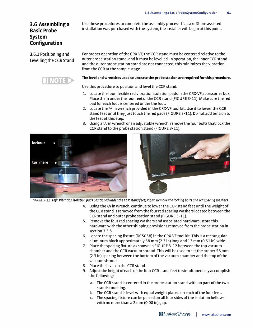
3.6 Assembling a Basic Probe System Configuration 61
3.6 Assembling a Basic Probe System Configuration
Use these procedures to complete the assembly process. If a Lake Shore assisted installation was purchased with the system, the installer will begin at this point.
3.6.1 Positioning and Levelling the CCR Stand
For proper operation of the CRX-VF, the CCR stand must be centered relative to the outer probe station stand, and it must be levelled. In operation, the inner CCR stand and the outer probe station stand are not connected; this minimizes the vibration from the CCR at the sample stage.
The level and wrenches used to uncrate the probe station are required for this procedure.
Use this procedure to position and level the CCR stand.
1. Locate the four flexible red vibration isolation pads in the CRX-VF accessories box. Place them under the four feet of the CCR stand (FIGURE 3-11). Make sure the red pad for each foot is centered under the foot.
2. Locate the ¾ in wrench provided in the CRX-VF tool kit. Use it to lower the CCR stand feet until they just touch the red pads (FIGURE 3-11). Do not add tension to the feet at this step.
3. Using a q in wrench or an adjustable wrench, remove the four bolts that lock the CCR stand to the probe station stand (FIGURE 3-11).
4. Using the ¾ in wrench, continue to lower the CCR stand feet until the weight of the CCR stand is removed from the four red spacing washers located between the CCR stand and outer probe station stand (FIGURE 3-11).
5. Remove the four red spacing washers and associated hardware; store this hardware with the other shipping provisions removed from the probe station in section 3.3.5
6. Locate the spacing fixture (DC5058) in the CRX-VF tool kit. This is a rectangular aluminum block approximately 58 mm (2.3 in) long and 13 mm (0.51 in) wide.
7. Place the spacing fixture as shown in FIGURE 3-12 between the top vacuum chamber and the CCR vacuum shroud. This will be used to set the proper 58 mm (2.3 in) spacing between the bottom of the vacuum chamber and the top of the vacuum shroud.
8. Place the level on the CCR stand. 9. Adjust the height of each of the four CCR stand feet to simultaneously accomplish
the following:
a. The CCR stand is centered in the probe station stand with no part of the two stands touching.
b. The CCR stand is level with equal weight placed on each of the four feet. c. The spacing fixture can be placed on all four sides of the isolation bellows
with no more than a 2 mm (0.08 in) gap.
FIGURE 3-11 Left: Vibration isolation pads positioned under the CCR stand feet; Right: Remove the locking bolts and red spacing washers
| www.lakeshore.com
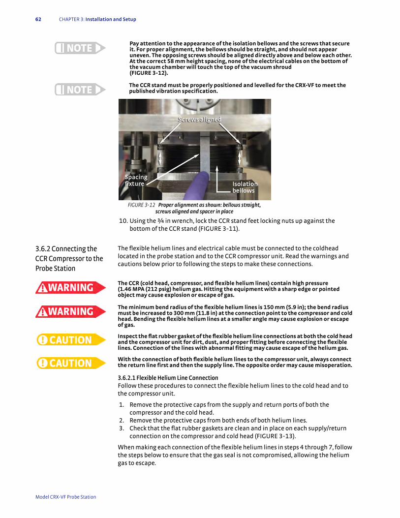
62 CHAPTER 3: Installation and Setup
Pay attention to the appearance of the isolation bellows and the screws that secure it. For proper alignment, the bellows should be straight, and should not appear uneven. The opposing screws should be aligned directly above and below each other. At the correct 58 mm height spacing, none of the electrical cables on the bottom of the vacuum chamber will touch the top of the vacuum shroud (FIGURE 3-12).
The CCR stand must be properly positioned and levelled for the CRX-VF to meet the published vibration specification.
10. Using the ¾ in wrench, lock the CCR stand feet locking nuts up against the bottom of the CCR stand (FIGURE 3-11).
3.6.2 Connecting the CCR Compressor to the Probe Station
The flexible helium lines and electrical cable must be connected to the coldhead located in the probe station and to the CCR compressor unit. Read the warnings and cautions below prior to following the steps to make these connections.
The CCR (cold head, compressor, and flexible helium lines) contain high pressure (1.46 MPA (212 psig) helium gas. Hitting the equipment with a sharp edge or pointed object may cause explosion or escape of gas.
The minimum bend radius of the flexible helium lines is 150 mm (5.9 in); the bend radius must be increased to 300 mm (11.8 in) at the connection point to the compressor and cold head. Bending the flexible helium lines at a smaller angle may cause explosion or escape of gas.
Inspect the flat rubber gasket of the flexible helium line connections at both the cold head and the compressor unit for dirt, dust, and proper fitting before connecting the flexible lines. Connection of the lines with abnormal fitting may cause escape of the helium gas.
With the connection of both flexible helium lines to the compressor unit, always connect the return line first and then the supply line. The opposite order may cause misoperation.
3.6.2.1 Flexible Helium Line ConnectionFollow these procedures to connect the flexible helium lines to the cold head and to the compressor unit.
1. Remove the protective caps from the supply and return ports of both the compressor and the cold head.
2. Remove the protective caps from both ends of both helium lines. 3. Check that the flat rubber gaskets are clean and in place on each supply/return
connection on the compressor and cold head (FIGURE 3-13).
When making each connection of the flexible helium lines in steps 4 through 7, follow the steps below to ensure that the gas seal is not compromised, allowing the helium gas to escape.
FIGURE 3-12 Proper alignment as shown: bellows straight, screws aligned and spacer in place
Model CRX-VF Probe Station
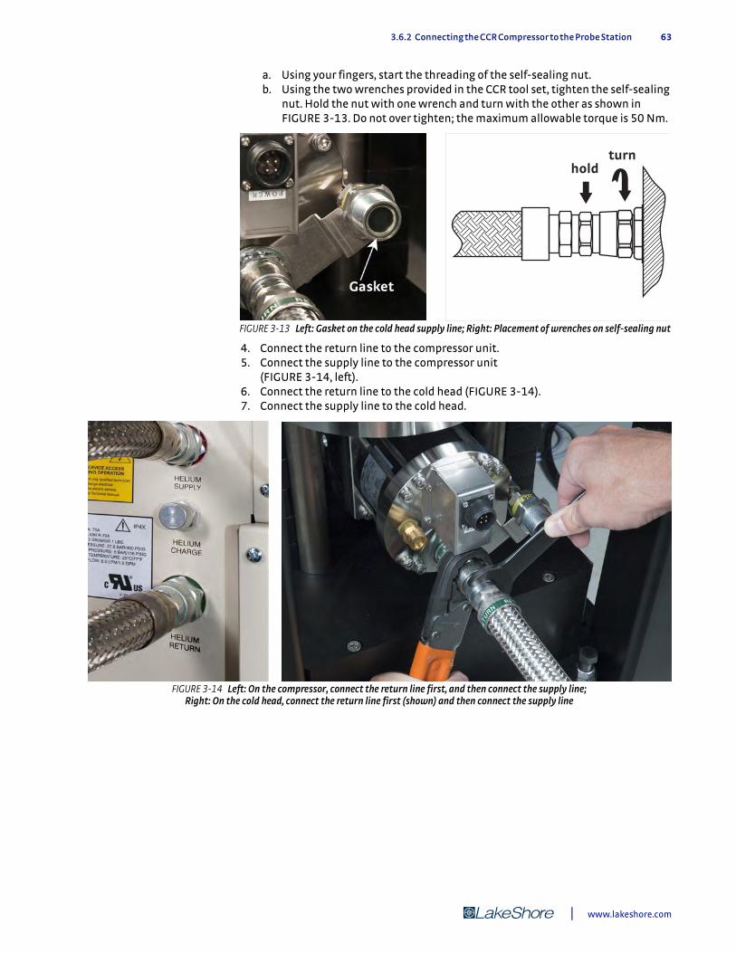
3.6.2 Connecting the CCR Compressor to the Probe Station 63
a. Using your fingers, start the threading of the self-sealing nut. b. Using the two wrenches provided in the CCR tool set, tighten the self-sealing
nut. Hold the nut with one wrench and turn with the other as shown in FIGURE 3-13. Do not over tighten; the maximum allowable torque is 50 Nm.
4. Connect the return line to the compressor unit. 5. Connect the supply line to the compressor unit
(FIGURE 3-14, left). 6. Connect the return line to the cold head (FIGURE 3-14). 7. Connect the supply line to the cold head..
FIGURE 3-13 Left: Gasket on the cold head supply line; Right: Placement of wrenches on self-sealing nut
holdturn
FIGURE 3-14 Left: On the compressor, connect the return line first, and then connect the supply line; Right: On the cold head, connect the return line first (shown) and then connect the supply line
| www.lakeshore.com
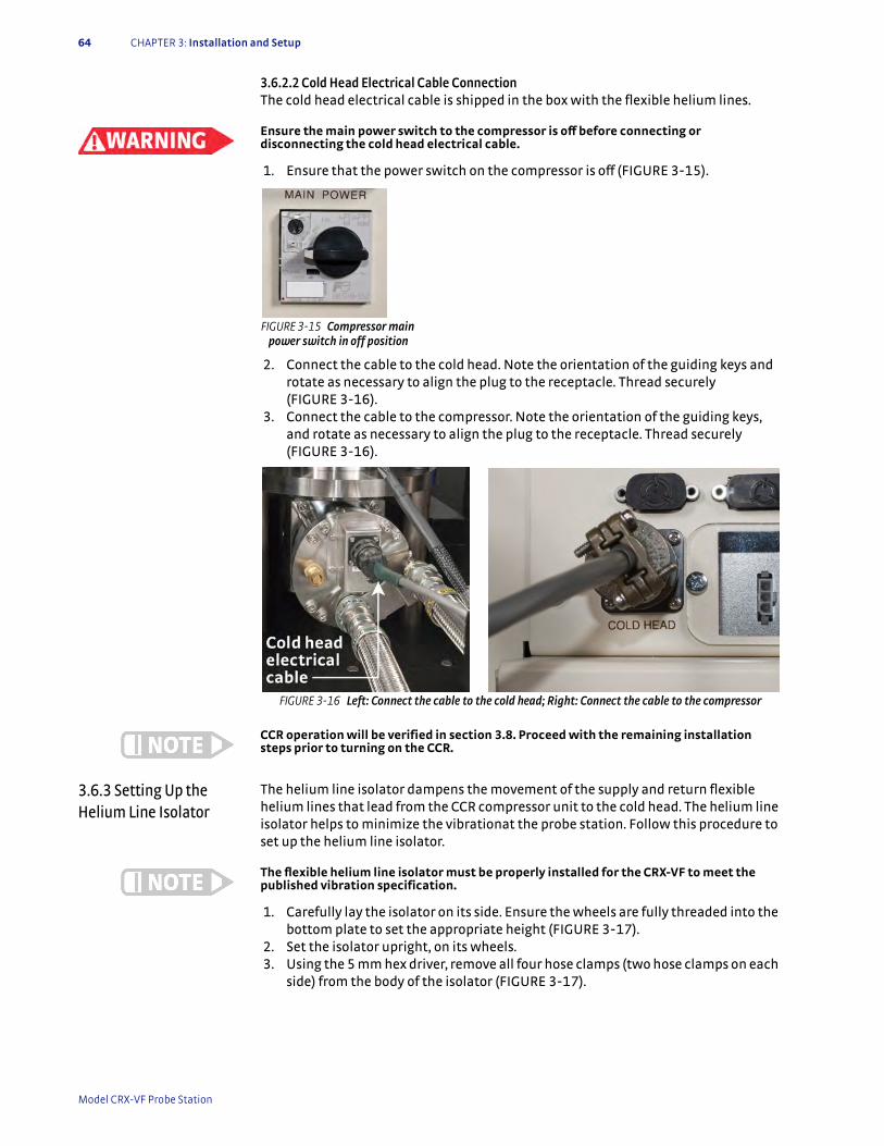
64 CHAPTER 3: Installation and Setup
3.6.2.2 Cold Head Electrical Cable Connection The cold head electrical cable is shipped in the box with the flexible helium lines.
Ensure the main power switch to the compressor is off before connecting or disconnecting the cold head electrical cable.
1. Ensure that the power switch on the compressor is off (FIGURE 3-15).
2. Connect the cable to the cold head. Note the orientation of the guiding keys and rotate as necessary to align the plug to the receptacle. Thread securely (FIGURE 3-16).
3. Connect the cable to the compressor. Note the orientation of the guiding keys, and rotate as necessary to align the plug to the receptacle. Thread securely (FIGURE 3-16).
CCR operation will be verified in section 3.8. Proceed with the remaining installation steps prior to turning on the CCR.
3.6.3 Setting Up the Helium Line Isolator
The helium line isolator dampens the movement of the supply and return flexible helium lines that lead from the CCR compressor unit to the cold head. The helium line isolator helps to minimize the vibrationat the probe station. Follow this procedure to set up the helium line isolator.
The flexible helium line isolator must be properly installed for the CRX-VF to meet the published vibration specification.
1. Carefully lay the isolator on its side. Ensure the wheels are fully threaded into the bottom plate to set the appropriate height (FIGURE 3-17).
2. Set the isolator upright, on its wheels. 3. Using the 5 mm hex driver, remove all four hose clamps (two hose clamps on each
side) from the body of the isolator (FIGURE 3-17).
FIGURE 3-15 Compressor main power switch in off position
FIGURE 3-16 Left: Connect the cable to the cold head; Right: Connect the cable to the compressor
Model CRX-VF Probe Station

3.6.3 Setting Up the Helium Line Isolator 65
4. Separate the metal clamps from the rubber isolators, and place two rubber isolators on each of the helium lines approximately 305 mm to 356 mm (12 in to 14 in) from the probe station (FIGURE 3-18).
5. Position the helium line isolator between the two helium lines (FIGURE 3-18), with the higher set of mounting holes toward the the supply line. There should be approximately 254 mm (10 in) of clearance between the probe station stand and the isolator (FIGURE 3-18)
.
6. Adjust the position of the rubber isolators to fit into the vertical slots on the isolator body.
7. Using the 5 mm hex driver, reattach the metal clamps over the rubber isolators. Tighten firmly.
8. Lock all four locking wheels.
FIGURE 3-17 Left: Finger tighten the locking wheel on the bottom of the helium line isolator; Right: Remove the hose clamps on both sides of the helium line isolator
FIGURE 3-18 Left: Rubber isolators on the helium lines; Middle: Helium line isolator between the helium lines; Right: Final position for the helium line isolator
| www.lakeshore.com
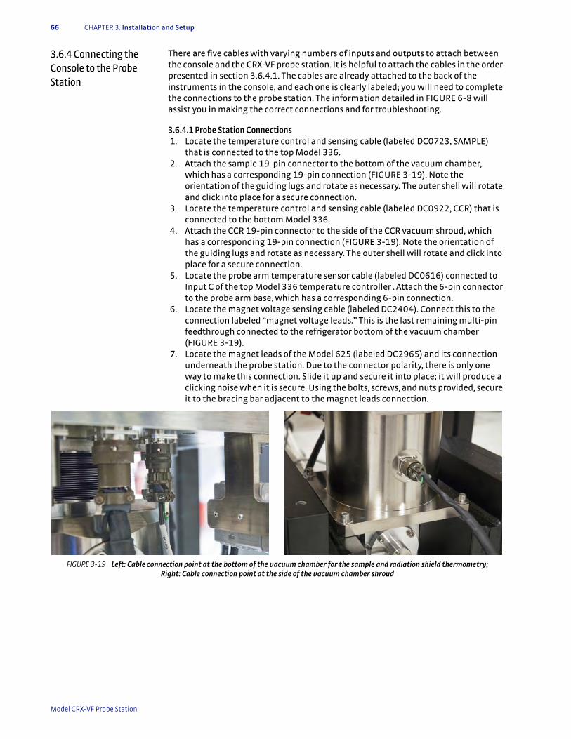
66 CHAPTER 3: Installation and Setup
3.6.4 Connecting the Console to the Probe Station
There are five cables with varying numbers of inputs and outputs to attach between the console and the CRX-VF probe station. It is helpful to attach the cables in the order presented in section 3.6.4.1. The cables are already attached to the back of the instruments in the console, and each one is clearly labeled; you will need to complete the connections to the probe station. The information detailed in FIGURE 6-8 will assist you in making the correct connections and for troubleshooting.
3.6.4.1 Probe Station Connections 1. Locate the temperature control and sensing cable (labeled DC0723, SAMPLE)
that is connected to the top Model 336. 2. Attach the sample 19-pin connector to the bottom of the vacuum chamber,
which has a corresponding 19-pin connection (FIGURE 3-19). Note the orientation of the guiding lugs and rotate as necessary. The outer shell will rotate and click into place for a secure connection.
3. Locate the temperature control and sensing cable (labeled DC0922, CCR) that is connected to the bottom Model 336.
4. Attach the CCR 19-pin connector to the side of the CCR vacuum shroud, which has a corresponding 19-pin connection (FIGURE 3-19). Note the orientation of the guiding lugs and rotate as necessary. The outer shell will rotate and click into place for a secure connection.
5. Locate the probe arm temperature sensor cable (labeled DC0616) connected to Input C of the top Model 336 temperature controller . Attach the 6-pin connector to the probe arm base, which has a corresponding 6-pin connection.
6. Locate the magnet voltage sensing cable (labeled DC2404). Connect this to the connection labeled “magnet voltage leads.” This is the last remaining multi-pin feedthrough connected to the refrigerator bottom of the vacuum chamber (FIGURE 3-19).
7. Locate the magnet leads of the Model 625 (labeled DC2965) and its connection underneath the probe station. Due to the connector polarity, there is only one way to make this connection. Slide it up and secure it into place; it will produce a clicking noise when it is secure. Using the bolts, screws, and nuts provided, secure it to the bracing bar adjacent to the magnet leads connection.
FIGURE 3-19 Left: Cable connection point at the bottom of the vacuum chamber for the sample and radiation shield thermometry; Right: Cable connection point at the side of the vacuum chamber shroud
Model CRX-VF Probe Station

3.6.5 Assembling the Vision System 67
3.6.5 Assembling the Vision System
FIGURE 3-20 illustrates the assembly of a single-post microscope, CCD camera and ring light. The vertical post, horizontal boom, microscope and CCD camera are connected to the CRX-VF baseplate. The position of the shaft collar determines the height of the microscope above the sample, and may require adjustment after assembly of the vision system.
3.6.5.1 Assemble the Vertical PostFollow this procedure to install the vertical post onto the baseplate. Depending on the microscope option and probe station model, the microscope post will have either one or two shafts. The Zoom 70 has one shaft and the Zoom 160 has two.
1. Install the microscope vertical post as shown in FIGURE 3-21. To install the post, remove the one or two M5 screws in the bottom of the post.
2. Align the post so that one of the two screw holes on the vertical post mount is over the hole that is closest to the vacuum chamber. The other screw hole will align with the third hole further away from the vacuum chamber.
3. Place the two M5 screws in their respective holes and finger tighten each one. 4. Using the 5 mm hex driver, tighten each one until secure.
FIGURE 3-20 Assembly of the vision system onto the probe station
Hand dial
Microscope
Ring light
Viewport
Chamber
Monitor
Horizontal boom(swing arm)
S-video cable
Color CCD camera
Optical fiber cable
Light source
Vertical post
| www.lakeshore.com
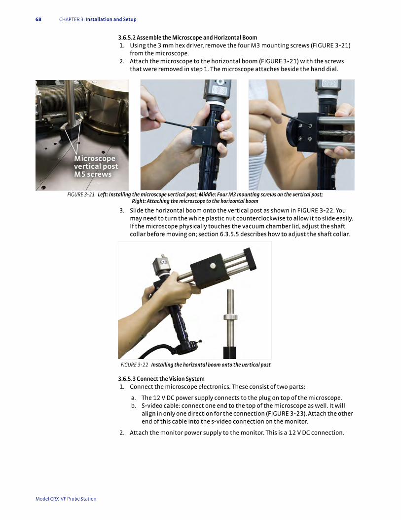
68 CHAPTER 3: Installation and Setup
3.6.5.2 Assemble the Microscope and Horizontal Boom 1. Using the 3 mm hex driver, remove the four M3 mounting screws (FIGURE 3-21)
from the microscope. 2. Attach the microscope to the horizontal boom (FIGURE 3-21) with the screws
that were removed in step 1. The microscope attaches beside the hand dial.
3. Slide the horizontal boom onto the vertical post as shown in FIGURE 3-22. You may need to turn the white plastic nut counterclockwise to allow it to slide easily. If the microscope physically touches the vacuum chamber lid, adjust the shaft collar before moving on; section 6.3.5.5 describes how to adjust the shaft collar.
3.6.5.3 Connect the Vision System 1. Connect the microscope electronics. These consist of two parts:
a. The 12 V DC power supply connects to the plug on top of the microscope. b. S-video cable: connect one end to the top of the microscope as well. It will
align in only one direction for the connection (FIGURE 3-23). Attach the other end of this cable into the s-video connection on the monitor.
2. Attach the monitor power supply to the monitor. This is a 12 V DC connection.
FIGURE 3-21 Left: Installing the microscope vertical post; Middle: Four M3 mounting screws on the vertical post; Right: Attaching the microscope to the horizontal boom
FIGURE 3-22 Installing the horizontal boom onto the vertical post
Model CRX-VF Probe Station
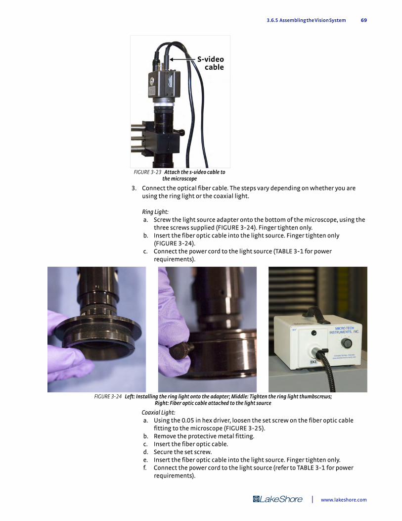
3.6.5 Assembling the Vision System 69
3. Connect the optical fiber cable. The steps vary depending on whether you are using the ring light or the coaxial light.
Ring Light: a. Screw the light source adapter onto the bottom of the microscope, using the
three screws supplied (FIGURE 3-24). Finger tighten only. b. Insert the fiber optic cable into the light source. Finger tighten only
(FIGURE 3-24). c. Connect the power cord to the light source (TABLE 3-1 for power
requirements).
Coaxial Light: a. Using the 0.05 in hex driver, loosen the set screw on the fiber optic cable
fitting to the microscope (FIGURE 3-25). b. Remove the protective metal fitting. c. Insert the fiber optic cable. d. Secure the set screw. e. Insert the fiber optic cable into the light source. Finger tighten only. f. Connect the power cord to the light source (refer to TABLE 3-1 for power
requirements).
FIGURE 3-23 Attach the s-video cable to the microscope
FIGURE 3-24 Left: Installing the ring light onto the adapter; Middle: Tighten the ring light thumbscrews; Right: Fiber optic cable attached to the light source
| www.lakeshore.com
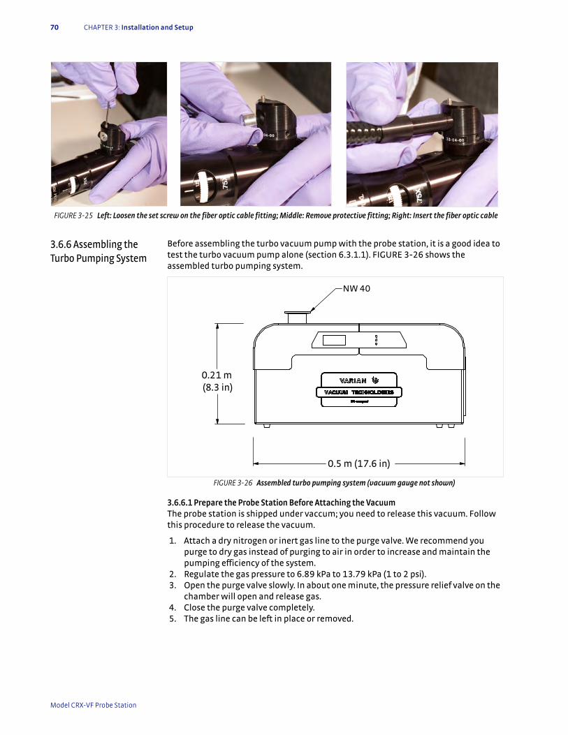
70 CHAPTER 3: Installation and Setup
3.6.6 Assembling the Turbo Pumping System
Before assembling the turbo vacuum pump with the probe station, it is a good idea to test the turbo vacuum pump alone (section 6.3.1.1). FIGURE 3-26 shows the assembled turbo pumping system.
3.6.6.1 Prepare the Probe Station Before Attaching the VacuumThe probe station is shipped under vaccum; you need to release this vacuum. Follow this procedure to release the vacuum.
1. Attach a dry nitrogen or inert gas line to the purge valve. We recommend you purge to dry gas instead of purging to air in order to increase and maintain the pumping efficiency of the system.
2. Regulate the gas pressure to 6.89 kPa to 13.79 kPa (1 to 2 psi). 3. Open the purge valve slowly. In about one minute, the pressure relief valve on the
chamber will open and release gas. 4. Close the purge valve completely. 5. The gas line can be left in place or removed.
FIGURE 3-25 Left: Loosen the set screw on the fiber optic cable fitting; Middle: Remove protective fitting; Right: Insert the fiber optic cable
FIGURE 3-26 Assembled turbo pumping system (vacuum gauge not shown)
0.5 m (17.6 in)
0.21 m (8.3 in)
NW 40
Model CRX-VF Probe Station
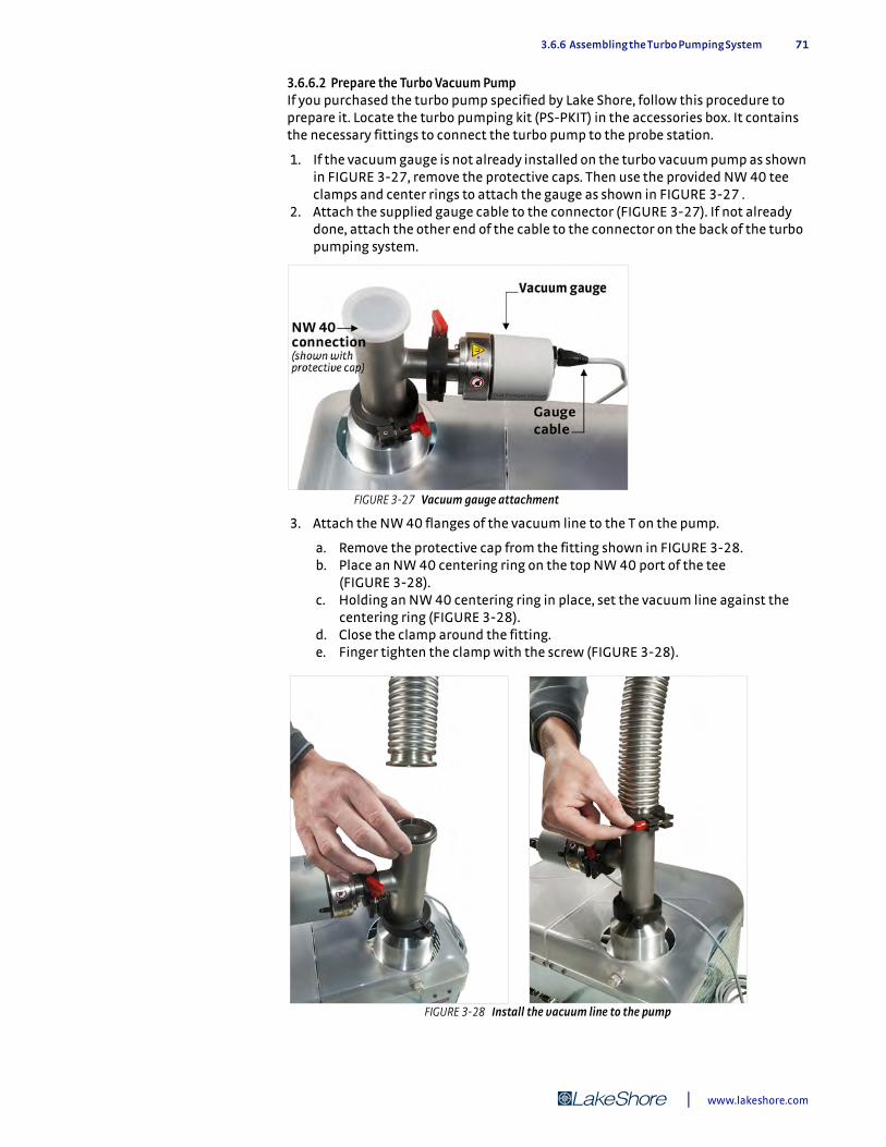
3.6.6 Assembling the Turbo Pumping System 71
3.6.6.2 Prepare the Turbo Vacuum PumpIf you purchased the turbo pump specified by Lake Shore, follow this procedure to prepare it. Locate the turbo pumping kit (PS-PKIT) in the accessories box. It contains the necessary fittings to connect the turbo pump to the probe station.
1. If the vacuum gauge is not already installed on the turbo vacuum pump as shown in FIGURE 3-27, remove the protective caps. Then use the provided NW 40 tee clamps and center rings to attach the gauge as shown in FIGURE 3-27 .
2. Attach the supplied gauge cable to the connector (FIGURE 3-27). If not already done, attach the other end of the cable to the connector on the back of the turbo pumping system.
3. Attach the NW 40 flanges of the vacuum line to the T on the pump.
a. Remove the protective cap from the fitting shown in FIGURE 3-28. b. Place an NW 40 centering ring on the top NW 40 port of the tee
(FIGURE 3-28). c. Holding an NW 40 centering ring in place, set the vacuum line against the
centering ring (FIGURE 3-28). d. Close the clamp around the fitting. e. Finger tighten the clamp with the screw (FIGURE 3-28).
FIGURE 3-27 Vacuum gauge attachment
FIGURE 3-28 Install the vacuum line to the pump
| www.lakeshore.com

72 CHAPTER 3: Installation and Setup
4. Remove the blank off plate from the NW 40 vacuum isolation valve on the probe station. The clamp and centering ring are used when the vacuum hose is attached in the next step.
5. Attach the other end of the vacuum line to the vacuum isolation valve on the probe station (FIGURE 3-29).
To minimize the transfer of vibration to the probe station, position the turbo pumping system so that the vacuum line has at least one 90° bend in it.
Do not remove or exchange the plastic clamp and centering ring installed between the isolation valve and the vacuum chamber. These electrically isolate the chamber from the turbo pumping system. This eliminates most of the electrical noise that might otherwise be coupled from the turbo pumping system to the probe station, and also eliminates a potential ground loop in the system.
6. Connect the power cord to the turbo pumping system (refer to TABLE 3-1 for power requirements).
3.6.7 Assembling Probe Station Options
Some options require some assembly, while others come fully assembled. This section explains how to assemble the options and attach them to the probe station.
3.6.7.1 Assembling the Pump Line Vibration Isolator (PS-PLVI-40)The PS-PLVI-40 is for the TPS FRG turbo pumping system. The pump line vibration isolator includes a bucket with NW 40 fittings and 1 m flexible stainless steel vacuum line. The bucket must be filled with pre-mix concrete to provide the vibration isolation. This requires approximately 40 kg (90 lb) of concrete (not included).
1. Mix the concrete according to directions provided with the concrete. 2. Fill the bucket with the mixture. 3. After the concrete has cured, turn the bucket handle-side up and place it on the
three rubber pads included with the kit (FIGURE 3-30). 4. Connect the bucket between the turbo pumping system and the probe station’s
vacuum isolation valve.
FIGURE 3-29 Use the clamp provided to attach the vacuum line to the CRX-VF probe station
Model CRX-VF Probe Station

3.7 Installing and Removing Probes 73
3.7 Installing and Removing Probes
Probes are installed at the ends of probe arms, inside the chamber. The chamber and radiation shield must be opened. It may also be helpful to remove the sample holder to make more room to work inside the chamber. Four ZN50 probes are included in the probe starter kit for training purposes.
The probes are packaged separately to protect the delicate tips. Do not touch the tips. Do not handle the alumina blade or the electrical conductors on the ZN50 probe with bare hands, as this may reduce its isolation. Wear nitrile gloves while changing blades.
3.7.1 Installing a Probe: Prep Instructions for All Probe Types
Follow this procedure to prepare for installation of all probe types, then use the unique instructions for each individual probe type.
1. Open the vacuum chamber and radiation shield using the guidelines in section 4.3.1 .
2. If you purchased semirigid cables or coaxial cables, there will be safety ties on the arms. Cut these off, and remove the ties from all cables. Be careful not to cut the Kapton® tape on the coaxial cables. You may need to use the x-axis hand dial to move the probe arms in or out so that the ties are more accessible.
3. Using the x-axis hand dial, extend the probe arm into the chamber until the probe arm set screws are accessible.
3.7.2 Installing a ZN50 Probe
The ZN50 series probes consist of a probe mount, ceramic blade with SMA electrical connector, and probe tip. Use the procedure in section 3.7.2.1 to install a ZN50 probe. If the probe mounts are already installed (FIGURE 3-31), go to section 3.7.2.2 and begin with installing the probe blade. If the probe mount is not installed, please be aware that some probe station users find it easier to first install the blade to the probe mount outside the station (section 3.7.2.2), and then install the probe to the probe arm.
FIGURE 3-30 Pump line vibration isolator
SMA connector
mount
blade
tip
| www.lakeshore.com
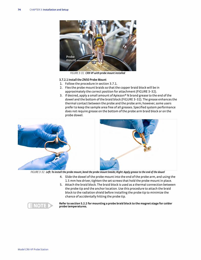
74 CHAPTER 3: Installation and Setup
3.7.2.1 Install the ZN50 Probe Mount 1. Follow the procedure in section 3.7.1. 2. Flex the probe mount braids so that the copper braid block will be in
approximately the correct position for attachment (FIGURE 3-32). 3. If desired, apply a small amount of Apiezon® N brand grease to the end of the
dowel and the bottom of the braid block (FIGURE 3-32). The grease enhances the thermal contact between the probe and the probe arm; however, some users prefer to keep the sample area free of all greases. Specified system performance does not require grease on the bottom of the probe arm braid block or on the probe dowel.
4. Slide the dowel of the probe mount into the end of the probe arm, and using the 1.5 mm hex driver, tighten the set screws that hold the probe mount in place.
5. Attach the braid block. The braid block is used as a thermal connection between the probe tip and the anchor location. Use this procedure to attach the braid block to the radiation shield before installing the probe tip to minimize the chance of accidentally hitting the probe tip.
Refer to section 5.2.2 for mounting a probe braid block to the magnet stage for colder probe temperatures.
FIGURE 3-31 CRX-VF with probe mount installed
FIGURE 3-32 Left: To install the probe mount, bend the probe mount braids; Right: Apply grease to the end of the dowel
Model CRX-VF Probe Station
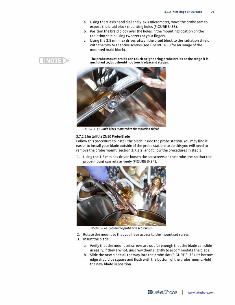
3.7.2 Installing a ZN50 Probe 75
a. Using the x-axis hand dial and y-axis micrometer, move the probe arm to expose the braid block mounting holes (FIGURE 3-33).
b. Position the braid block over the holes in the mounting location on the radiation shield using tweezers or your fingers.
c. Using the 2.5 mm hex driver, attach the braid block to the radiation shield with the two M3 captive screws (see FIGURE 3-33 for an image of the mounted braid block).
The probe mount braids can touch neighboring probe braids or the stage it is anchored to, but should not touch adjacent stages.
3.7.2.2 Install the ZN50 Probe BladeFollow this procedure to install the blade inside the probe station. You may find it easier to install your blade outside of the probe station; to do this you will need to remove the probe mount (section 3.7.3.2) and follow the procedures in step 3.
1. Using the 1.5 mm hex driver, loosen the set screws on the probe arm so that the probe mount can rotate freely (FIGURE 3-34).
2. Rotate the mount so that you have access to the mount set screw. 3. Insert the blade:
a. Verify that the mount set screws are out far enough that the blade can slide in easily. If they are not, unscrew them slightly to accommodate the blade.
b. Slide the new blade all the way into the probe slot (FIGURE 3-35). Its bottom edge should be square and flush with the bottom of the probe mount. Hold the new blade in position.
FIGURE 3-33 Braid block mounted to the radiation shield
FIGURE 3-34 Loosen the probe arm set screws
| www.lakeshore.com
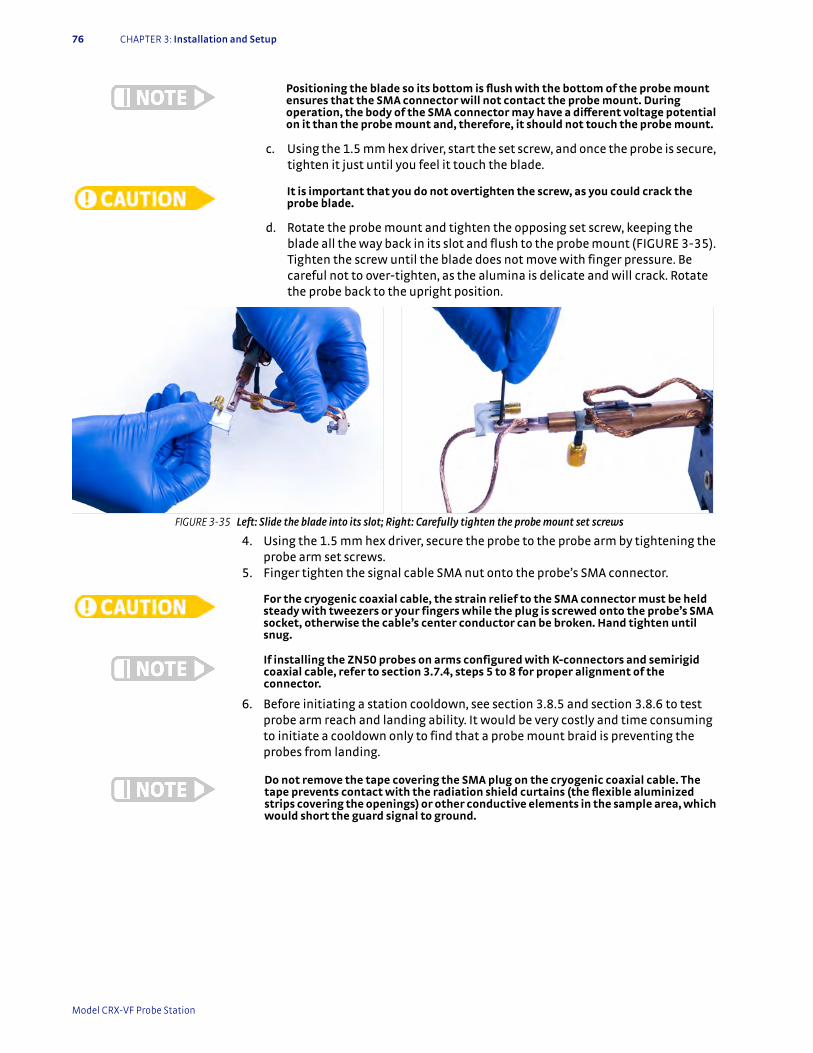
76 CHAPTER 3: Installation and Setup
Positioning the blade so its bottom is flush with the bottom of the probe mount ensures that the SMA connector will not contact the probe mount. During operation, the body of the SMA connector may have a different voltage potential on it than the probe mount and, therefore, it should not touch the probe mount.
c. Using the 1.5 mm hex driver, start the set screw, and once the probe is secure, tighten it just until you feel it touch the blade.
It is important that you do not overtighten the screw, as you could crack the probe blade.
d. Rotate the probe mount and tighten the opposing set screw, keeping the blade all the way back in its slot and flush to the probe mount (FIGURE 3-35). Tighten the screw until the blade does not move with finger pressure. Be careful not to over-tighten, as the alumina is delicate and will crack. Rotate the probe back to the upright position.
4. Using the 1.5 mm hex driver, secure the probe to the probe arm by tightening the probe arm set screws.
5. Finger tighten the signal cable SMA nut onto the probe’s SMA connector.
For the cryogenic coaxial cable, the strain relief to the SMA connector must be held steady with tweezers or your fingers while the plug is screwed onto the probe’s SMA socket, otherwise the cable’s center conductor can be broken. Hand tighten until snug.
If installing the ZN50 probes on arms configured with K-connectors and semirigid coaxial cable, refer to section 3.7.4, steps 5 to 8 for proper alignment of the connector.
6. Before initiating a station cooldown, see section 3.8.5 and section 3.8.6 to test probe arm reach and landing ability. It would be very costly and time consuming to initiate a cooldown only to find that a probe mount braid is preventing the probes from landing.
Do not remove the tape covering the SMA plug on the cryogenic coaxial cable. The tape prevents contact with the radiation shield curtains (the flexible aluminized strips covering the openings) or other conductive elements in the sample area, which would short the guard signal to ground.
FIGURE 3-35 Left: Slide the blade into its slot; Right: Carefully tighten the probe mount set screws
Model CRX-VF Probe Station
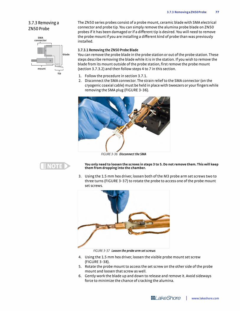
3.7.3 Removing a ZN50 Probe 77
3.7.3 Removing a ZN50 Probe
The ZN50 series probes consist of a probe mount, ceramic blade with SMA electrical connector and probe tip. You can simply remove the alumina probe blade on ZN50 probes if it has been damaged or if a different tip is desired. You will need to remove the probe mount if you are installing a different kind of probe than was previously installed.
3.7.3.1 Removing the ZN50 Probe BladeYou can remove the probe blade in the probe station or out of the probe station. These steps describe removing the blade while it is in the station. If you wish to remove the blade from its mount outside of the probe station, first remove the probe mount (section 3.7.3.2) and then follow steps 4 to 7 in this section.
1. Follow the procedure in section 3.7.1. 2. Disconnect the SMA connector. The strain relief to the SMA connector (on the
cryogenic coaxial cable) must be held in place with tweezers or your fingers while removing the SMA plug (FIGURE 3-36).
You only need to loosen the screws in steps 3 to 5. Do not remove them. This will keep them from dropping into the chamber.
3. Using the 1.5 mm hex driver, loosen both of the M3 probe arm set screws two to three turns (FIGURE 3-37) to rotate the probe to access one of the probe mount set screws.
4. Using the 1.5 mm hex driver, loosen the visible probe mount set screw (FIGURE 3-38).
5. Rotate the probe mount to access the set screw on the other side of the probe mount and loosen that screw as well.
6. Gently work the blade up and down to release and remove it. Avoid sideways force to minimize the chance of cracking the alumina.
SMA connector
mount
blade
tip
FIGURE 3-36 Disconnect the SMA
FIGURE 3-37 Loosen the probe arm set screws
| www.lakeshore.com

78 CHAPTER 3: Installation and Setup
7. Remove the blade from the system and place it back into its storage case, making sure not to contact the delicate probe tip.
3.7.3.2 Removing the ZN50 Probe Mount 1. If you have not yet removed the blade, you will need to disconnect the SMA
connector. The strain relief to the SMA connector (on the cryogenic coaxial cable) must be held in place with tweezers or your fingers while removing the SMA plug.
2. Using the x-axis hand dial and the y-axis micrometer, move the probe arm to expose the braid block mounting holes on the radiation shield.
3. Using the 2.5 mm hex driver, loosen the two captive screws on the braid block (FIGURE 3-33).
4. Pull the braid block out. 5. Using the 1.5 mm hex driver, loosen both M3 probe arm set screws two to three
turns and slide the dowel out of the probe arm (FIGURE 3-34). 6. Pull the probe mount out of the probe station.
3.7.4 Installing a Microwave Probe
The K-connector and the V-connector look very similar; however, they may not mate to a connector of different frequency rating and the probe or cable may be damaged if forced to thread to an improper mate. See section 2.5.1 for more information. Contact Lake Shore if you are still unsure of your probe station’s microwave configuration.
Unlike the ZN50 blade and optical fiber assemblies that use a separate probe mount, the microwave probe has an integrated mount that attaches to the probe arm, and includes probe mount braids and a braid block for attachment to the thermal anchor point.
GSG microwave probe tips are extremely delicate; the slightest touch on the probe tips can disturb the ground-signal-ground (GSG) transmission line geometry, thereby degrading performance. Due to the high cost of replacement microwave probes, we highly recommend that users become comfortable with probing techniques using ZN50 probes prior to installing and probing with microwave probes to avoid damage to the microwave probe tips (Lake Shore provides two ZN50-25-BECU and two ZN50-25-W probe tips in the probe starter kit).
Follow this procedure to install a microwave probe. If a ZN50 or optical fiber probe mount is installed in your probe station, you will need to remove it first (section 3.7.3.2 or section 5.3.7.1).
1. Follow steps 1 to 3 in section 3.7.1. 2. Remove a microwave probe from its storage case.
FIGURE 3-38 Loosening the probe mount set screws
Model CRX-VF Probe Station
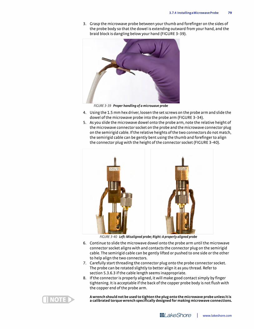
3.7.4 Installing a Microwave Probe 79
3. Grasp the microwave probe between your thumb and forefinger on the sides of the probe body so that the dowel is extending outward from your hand, and the braid block is dangling below your hand (FIGURE 3-39).
4. Using the 1.5 mm hex driver, loosen the set screws on the probe arm and slide the dowel of the microwave probe into the probe arm (FIGURE 3-34).
5. As you slide the microwave dowel onto the probe arm, note the relative height of the microwave connector socket on the probe and the microwave connector plug on the semirigid cable. If the relative heights of the two connectors do not match, the semirigid cable can be gently bent using the thumb and forefinger to align the connector plug with the height of the connector socket (FIGURE 3-40).
6. Continue to slide the microwave dowel onto the probe arm until the microwave connector socket aligns with and contacts the connector plug on the semirigid cable. The semirigid cable can be gently lifted or pushed to one side or the other to help align the two connectors.
7. Carefully start threading the connector plug onto the probe connector socket. The probe can be rotated slightly to better align it as you thread. Refer to section 5.3.6.3 if the cable length seems inappropriate.
8. If the connector is properly aligned, it will make good contact simply by finger tightening. It is acceptable if the back of the copper probe body is not flush with the copper end of the probe arm.
A wrench should not be used to tighten the plug onto the microwave probe unless it is a calibrated torque wrench specifically designed for making microwave connections.
FIGURE 3-39 Proper handling of a microwave probe
FIGURE 3-40 Left: Misaligned probe; Right: A properly aligned probe
| www.lakeshore.com
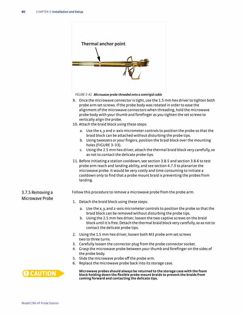
80 CHAPTER 3: Installation and Setup
9. Once the microwave connector is tight, use the 1.5 mm hex driver to tighten both probe arm set screws. If the probe body was rotated in order to ease the alignment of the microwave connectors when threading, hold the microwave probe body with your thumb and forefinger as you tighten the set screws to vertically align the probe.
10. Attach the braid block using these steps:
a. Use the x, y and z-axis micrometer controls to position the probe so that the braid block can be attached without disturbing the probe tips.
b. Using tweezers or your fingers, position the braid block over the mounting holes (FIGURE 3-33).
c. Using the 2.5 mm hex driver, attach the thermal braid block very carefully, so as not to contact the delicate probe tips.
11. Before initiating a station cooldown, see section 3.8.5 and section 3.8.6 to test probe arm reach and landing ability, and see section 4.7.3 to planarize the microwave probe. It would be very costly and time consuming to initiate a cooldown only to find that a probe mount braid is preventing the probes from landing.
3.7.5 Removing a Microwave Probe
Follow this procedure to remove a microwave probe from the probe arm.
1. Detach the braid block using these steps:
a. Use the x, y, and z-axis micrometer controls to position the probe so that the braid block can be removed without disturbing the probe tips.
b. Using the 2.5 mm hex driver, loosen the two captive screws on the braid block until it is free. Detach the thermal braid block very carefully, so as not to contact the delicate probe tips.
2. Using the 1.5 mm hex driver, loosen both M3 probe arm set screws two to three turns.
3. Carefully loosen the connector plug from the probe connector socket. 4. Grasp the microwave probe between your thumb and forefinger on the sides of
the probe body. 5. Slide the microwave probe off the probe arm. 6. Replace the microwave probe back into its storage case.
Microwave probes should always be returned to the storage case with the foam block holding down the flexible probe mount braids to prevent the braids from coming forward and contacting the delicate tips.
FIGURE 3-41 Microwave probe threaded onto a semirigid cable
Model CRX-VF Probe Station

3.8 System Verification and Testing 81
3.8 System Verification and Testing
This section describes a sequence of short tests that can be used to verify that the probe station has been assembled correctly and is in good working order. These tests should be done after making changes to the probe station configuration but before cooling down the system. The goal is to find small problems before investing the time and resources into cooling the system.
These procedures assume that the station has been fully assembled as described in section 3.6.
3.8.1 Console Verification
The instrument console is a housing cabinet that includes two Model 336 temperature controllers.
3.8.1.1 Verifying VoltagesThe console is shipped from Lake Shore with user specified line voltage selected. If the system is being moved, or there is any reason to believe the voltage may not be appropriate for the installation site, please verify line voltage settings. The Model 336 temperature controllers have a voltage selection with the same design fuse casing. From the back of the console, look at the voltage selection window to find the voltage setting. Refer to the Model 336 user’s manual if you need to change the voltage.
3.8.1.2 Verify Power OnThe Model 336 controllers are plugged into the power strip inside the console. First plug in the console power strip (see TABLE 3-1 for power requirements); then, verify that all the power on switches on the back of the controllers are in the on position.
On the front right hand side of the console, near the bottom, you will find a rocker switch. This is the main power switch. Turn it on.
3.8.1.3 Verifying the Model 336 Control SettingsThe control settings for the Model 336 temperature controllers are set at Lake Shore; however, it is good to verify them for safety purposes and to acquaint yourself with the controller. You can use TABLE 4-3 and TABLE 4-4 in section 4.5.9 to assist you in verifying or resetting it. You can find more information on the controller in its manual.
3.8.1.4 Verifying the Model 625 SettingsYou can verify that the power supply parameters are properly set on the Model 625 using the key in TABLE 4-6. These settings are necessary to protect the CRX-VF magnet.
If the power supply is not properly set up, discontinue this procedure and contact Lake Shore for assistance. You can find contact information in section 6.5.
3.8.2 Temperature Sensor and Heater Test
Each of the five stages in the CRX-VF (sample stage, magnet stage, radiation shield stage and cryocooler first and second stages) has a temperature sensor and heater. For standard configuration, the CCR 2nd stage heater is not used. Prior to heating or cooling the system it is important to verify that the sensor, heater, cabling, and temperature controller are all configured properly. If any of the control loop wiring is mixed up or a sensor is malfunctioning, it is possible for the system to overheat and become damaged during warm up. You can check the instrumentation wiring diagram if your probe station does not perform as these tests suggest (FIGURE 6-8).
Use steps 1 to 4 to prepare the system for the sensor and heater test. Then use TABLE 3-7 to run the sensor and heater test.
| www.lakeshore.com
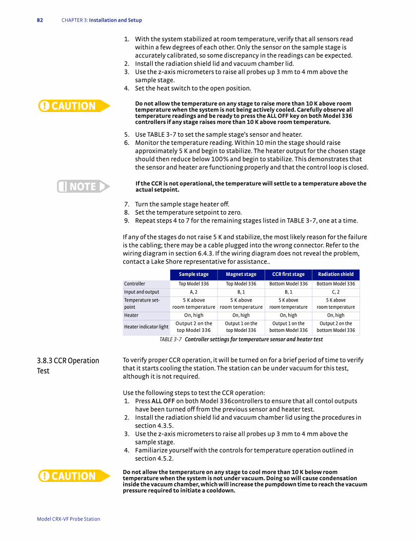
82 CHAPTER 3: Installation and Setup
1. With the system stabilized at room temperature, verify that all sensors read within a few degrees of each other. Only the sensor on the sample stage is accurately calibrated, so some discrepancy in the readings can be expected.
2. Install the radiation shield lid and vacuum chamber lid. 3. Use the z-axis micrometers to raise all probes up 3 mm to 4 mm above the
sample stage. 4. Set the heat switch to the open position.
Do not allow the temperature on any stage to raise more than 10 K above room temperature when the system is not being actively cooled. Carefully observe all temperature readings and be ready to press the ALL OFF key on both Model 336 controllers if any stage raises more than 10 K above room temperature.
5. Use TABLE 3-7 to set the sample stage’s sensor and heater. 6. Monitor the temperature reading. Within 10 min the stage should raise
approximately 5 K and begin to stabilize. The heater output for the chosen stage should then reduce below 100% and begin to stabilize. This demonstrates that the sensor and heater are functioning properly and that the control loop is closed.
If the CCR is not operational, the temperature will settle to a temperature above the actual setpoint.
7. Turn the sample stage heater off. 8. Set the temperature setpoint to zero. 9. Repeat steps 4 to 7 for the remaining stages listed in TABLE 3-7, one at a time.
If any of the stages do not raise 5 K and stabilize, the most likely reason for the failure is the cabling; there may be a cable plugged into the wrong connector. Refer to the wiring diagram in section 6.4.3. If the wiring diagram does not reveal the problem, contact a Lake Shore representative for assistance..
3.8.3 CCR Operation Test
To verify proper CCR operation, it will be turned on for a brief period of time to verify that it starts cooling the station. The station can be under vacuum for this test, although it is not required.
Use the following steps to test the CCR operation: 1. Press ALL OFF on both Model 336controllers to ensure that all contol outputs
have been turned off from the previous sensor and heater test. 2. Install the radiation shield lid and vacuum chamber lid using the procedures in
section 4.3.5. 3. Use the z-axis micrometers to raise all probes up 3 mm to 4 mm above the
sample stage. 4. Familiarize yourself with the controls for temperature operation outlined in
section 4.5.2.
Do not allow the temperature on any stage to cool more than 10 K below room temperature when the system is not under vacuum. Doing so will cause condensation inside the vacuum chamber, which will increase the pumpdown time to reach the vacuum pressure required to initiate a cooldown.
Sample stage Magnet stage CCR first stage Radiation shield
Controller Top Model 336 Top Model 336 Bottom Model 336 Bottom Model 336
Input and output A, 2 B, 1 B, 1 C, 2
Temperature set-point
5 K above room temperature
5 K above room temperature
5 K above room temperature
5 K above room temperature
Heater On, high On, high On, high On, high
Heater indicator lightOutput 2 on the top Model 336
Output 1 on the top Model 336
Output 1 on the bottom Model 336
Output 2 on the bottom Model 336
TABLE 3-7 Controller settings for temperature sensor and heater test
Model CRX-VF Probe Station

3.8.4 Microscope Light and Focus Test 83
5. Follow the procedure in section 4.5.3.2 to start the CCR and run it for 30 s. The CCR second stage and the CCR first stage sensors should start to decrease in temperature which indicates that the CCR is operating properly.
6. Press the CCR OFF button.
The sample stage, magnet stage, and radiation shield stage will also start to lower in temperature after a delay, but it is not required to wait to see these stages drop in temperature to verify proper CCR performance.
If the CCR second stage and CCR first stage sensors do not register a drop in temperature after 1 min of operation, refer to section 6.3.2 CCR troubleshooting. If the steps listed there do not reveal the problem, contact a Lake Shore representative for assistance.
3.8.4 Microscope Light and Focus Test
Follow this procedure to ensure that the microscope focuses properly on the sample stage. See section 2.3.6.1 for a sample of approximate focal clarity when you use the focus aid with the Zoom 70 and Zoom 160.
1. Place a piece of sample material or sample substrate on the sample holder. We recommend using an optical target such as the U.S.A.F. optical target for resolution verification.
2. Install the radiation shield lid and the vacuum chamber lid (see section 4.3.5). 3. Refer to section 4.7.1 to use the microscope to image the sample. 4. If the microscope will not focus on the target, refer to section 6.3.5. 5. If the image is not oriented as desired, refer to section 6.3.5.8.
3.8.5 Testing the Probe Arm Reach
Follow this procedure to check the probe arm reach.
1. Remove the vacuum chamber lid and radiation shield lid (section 4.3.1). 2. Use the z-axis micrometers to raise all probes up 3 mm to 4 mm above the
sample stage. 3. Slowly move one probe towards the sample stage using the x-axis hand dial. 4. Watch for interference of the probe, cable connector and blades. 5. Using the x and y-micrometers to adjust position, move the probe (it should
travel smoothly) until the probe tip reaches all sides of the specified 25 mm (1 in) diameter probe area (see FIGURE 4-1 for probe area).
6. Retract the probe and repeat for all other probes.
Check arm reach one probe arm at a time. Retract the previously checked arm before advancing a second arm into the sample area. Failure to comply may result in probe tip damage.
3.8.6 Probe Continuity Test
Follow this procedure to ensure that the probes have been installed correctly and will transmit a signal when probing a sample. The radiation and vacuum chamber lids do not need to be installed. This procedure should be performed whenever a probe arm or probe has been changed.
Do not perform this test on microwave probes unless there is a specific concern. The microwave semirigid cables and connectors seldom have continuity problems. Failure to comply may result in probe tip damage.
1. Land each probe tip on the top surface of the grounded sample holder (section 4.7.2).
2. Using a multimeter, measure continuity (resistance) between each adjacent pair of probes.
3. A bad probe assembly can be identified if it does not show continuity (low resistance) with the probes on either side.
4. If a probe assembly appears bad, first re-land the probe to make sure it is touching the sample stage, then refer to section 6.3.6.
| www.lakeshore.com
84 CHAPTER 3: Installation and Setup
3.8.7 Vacuum Chamber Leak Test
Follow this procedure to verify vacuum chamber integrity.
1. Test the turbo vacuum pump along with the connection to the probe station (section 6.3.1.2).
2. Test the turbo vacuum pump, connection to the probe station, and the probe station vacuum chamber (section 6.3.1.3).
Failure to turn off and properly vent the vacuum pump before opening the vacuum isolation valve may result in damage to your vacuum pumping system.
Model CRX-VF Probe Station
4.1 General 85
Chapter 4: Basic Operation
4.1 General This chapter describes the majority of daily operation. Chapter 5 covers more advanced probe station operation. It is assumed that the station has been installed and set up as described in Chapter 3.
4.1.1 Common Operational Mistakes
The following are some common mistakes that can be made while operating the probe station. These mistakes can result in costly damage to the probes or sample cooling assembly. Please read this chapter thoroughly before operating the probe station for the first time so that these and other mistakes can be avoided.
D Opening the vacuum chamber to atmosphere with a cold sample cooling assembly
D Heating the sample cooling assembly when it is not under vacuum D Heating the sample cooling assembly when the CCR is off D Not raising the probe tips before evacuating the chamberD Not raising the probe tips before changing temperature D Not checking that all probe tips can contact the sample under test before
cooling down D Energizing the magnet with the magnet above the operational safe temperature
for fieldD Moving the heat switch from the Rad or Open position to Base with the magnet
energized
4.1.2 Temperature Limits
The maximum temperature limits for the multiple stages and components of the probe station are listed below. Adhere to these limits at all times during probe station operation.
Optional probes and sample holders may have lower maximum temperatures. Failure to observe maximum temperatures may result in equipment damage.
4.2 Operating the Probe Arm Translation Stages
Each probe assembly includes a micro-manipulated translation stage with three axes of motion that are described in this section. All six available probes can be positioned in a 25 mm (1 in) diameter probe area in the center of the sample holder (FIGURE 4-1). The CRX-VF can accommodate 32 mm (1.25) and 51 mm (2 in) sample holders, but the probe area is the same for both sizes. Individual probes can land outside the probe area in line with the probe arm. Due to translation limitations, individual probes cannot be landed on either side of the defined probe area. The sample should be positioned and aligned on the sample holder to take best advantage of the probe area (see section 4.3.3.1).
Before evacuating the vacuum chamber or making significant temperature changes, use the z-axis micrometers to raise all probes up 3 mm to 4 mm above the sample. Failure to do so will potentially cause damage to the probe tip or scratch the sample surface.
Sample stage: 500 KMagnet stage 300 KRadiation shield stage: 350 KCryocooler first stage: 300 KCryocooler second stage 300 KProbe arms: 350 K
| www.lakeshore.com

86 CHAPTER 4: Basic Operation
Normal motion of the translation stages remains smooth with constant turning force throughout the usable range. It is normal, however, for additional tension to occur when the system is under vacuum as compared to when it is open. Restrictions in motion are normally caused by the stage coming to the end of its travel. Restriction can sometimes also be caused by interference inside the chamber. In either case, never force one of the controls or damage to the probe or sample cooling assembly may result. Instead, remove the vacuum chamber lid and radiation shield (section 4.3.1), and identify the restriction before proceeding.
The probe arm translation stage has a greater range of motion than is accommodated by the CRX-VF sample stage and magnet stage. When moving the probe beyond the sample holder, take precautions to ensure nothing interferes with the probe, or you may risk damaging the probe tip.
The following translation stage controls are used to position the probe. Please note that these instructions apply only to stages like the one pictured in FIGURE 4-2. Other probe station models will operate differently.
The x-axis hand dial is used to move the probe in and out (in the probe arm axis) with a total travel of 51 mm (2 in). Turning the hand dial clockwise moves the probe toward the sample. The graduated scale on the side of the stage shows 1 mm divisions. The graduated scale on the hand dial shows 0.02 mm divisions.
The y-axis micrometer is used to move the probe from side to side (along the plane of the sample perpendicular to the probe axis) with a total travel of 25 mm (1 in). Turning the micrometer clockwise moves the probe to the left. One complete revolution of the micrometer moves the probe 0.5 mm. The graduated scale on the outside of the micrometer shows 0.01 mm divisions.
The z-axis micrometer is used to move the probe up and down (vertically) with a total travel of 17 mm (0.71 in). Turning the micrometer clockwise moves the probe down. One complete revolution of the micrometer moves the probe 0.5 mm. The graduated scale on the outside of the micrometer shows 0.01 mm divisions.
For those probe assemblies that are shipped with microwave probes, planarization (rotation) of the probe arm is described in section 4.7.3. Procedures to install the planarization assembly are in section 5.3.8.
FIGURE 4-1 Probe area indicated with blue circle
Model CRX-VF Probe Station
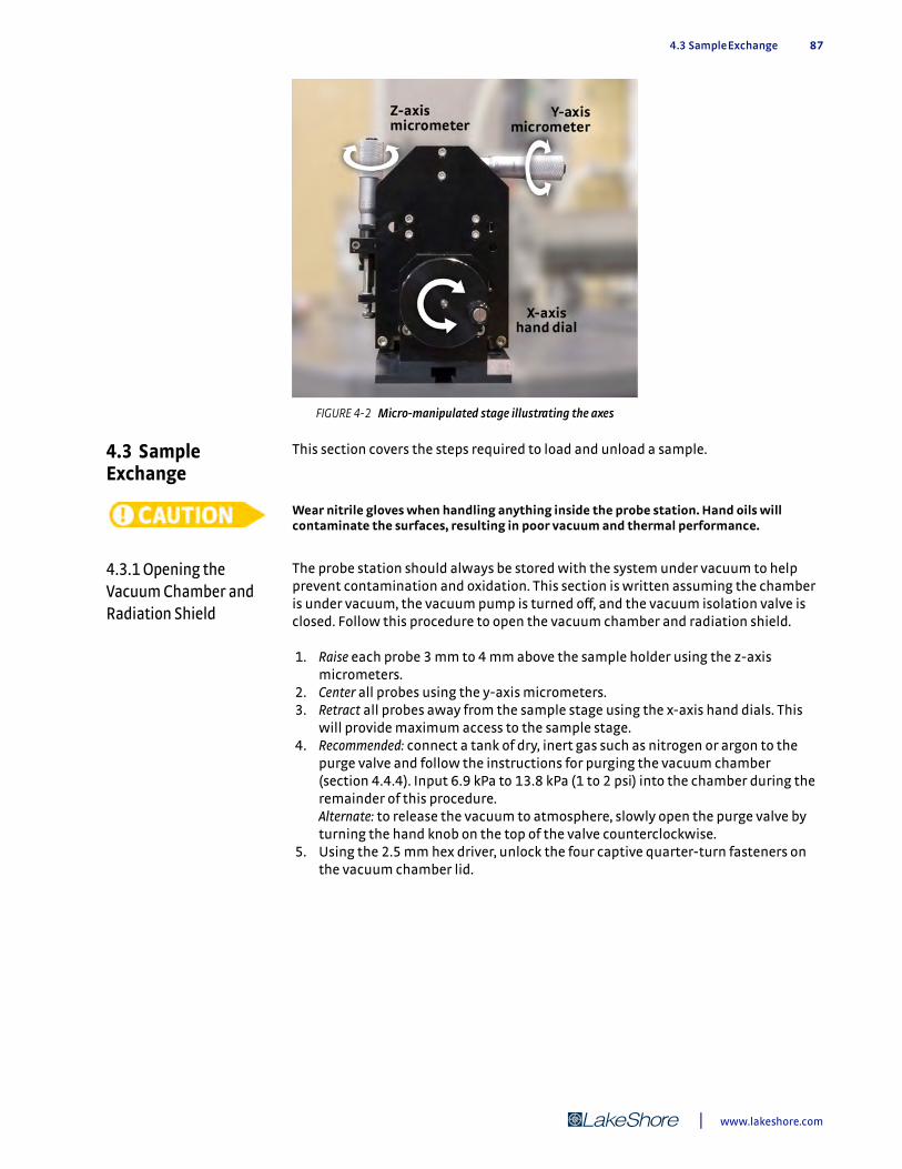
4.3 Sample Exchange 87
4.3 Sample Exchange
This section covers the steps required to load and unload a sample.
Wear nitrile gloves when handling anything inside the probe station. Hand oils will contaminate the surfaces, resulting in poor vacuum and thermal performance.
4.3.1 Opening the Vacuum Chamber and Radiation Shield
The probe station should always be stored with the system under vacuum to help prevent contamination and oxidation. This section is written assuming the chamber is under vacuum, the vacuum pump is turned off, and the vacuum isolation valve is closed. Follow this procedure to open the vacuum chamber and radiation shield.
1. Raise each probe 3 mm to 4 mm above the sample holder using the z-axis micrometers.
2. Center all probes using the y-axis micrometers. 3. Retract all probes away from the sample stage using the x-axis hand dials. This
will provide maximum access to the sample stage. 4. Recommended: connect a tank of dry, inert gas such as nitrogen or argon to the
purge valve and follow the instructions for purging the vacuum chamber (section 4.4.4). Input 6.9 kPa to 13.8 kPa (1 to 2 psi) into the chamber during the remainder of this procedure. Alternate: to release the vacuum to atmosphere, slowly open the purge valve by turning the hand knob on the top of the valve counterclockwise.
5. Using the 2.5 mm hex driver, unlock the four captive quarter-turn fasteners on the vacuum chamber lid.
FIGURE 4-2 Micro-manipulated stage illustrating the axes
| www.lakeshore.com

88 CHAPTER 4: Basic Operation
6. Pull up gently on the lid to remove it. A light bump may be required to release the o-ring seal if the chamber was closed for a long time.
7. Place the vacuum chamber lid in a safe place where it will not get scratched or contaminated.
8. Using the 2.5 mm hex driver, loosen the eight M3 screws from the outer edge of the radiation shield lid. The screws are captive and stay with the radiation shield lid.
9. Place the radiation shield lid with the vacuum chamber lid. Bumpers are built into the radiation shield lid for it to rest on.
4.3.2 Removing the Sample Holder
Follow this procedure to remove the sample holder.
1. If you are removing an optional triaxial or coaxial sample holder, disconnect the signal cable before removing the sample holder from the sample stage (FIGURE 4-4). Using tweezers or your fingers, pull the cable plug out of the sam-ple holder socket. The cable can be left as shown in FIGURE 4-4.
Be very careful that the tweezers do not slip off the cable plug and onto the wire, where they can accidentally pull the wire out of the connector.
2. Screw the lifter tool into the sample holder. There are two holes available for the lifter. Use the most convenient (FIGURE 4-5).
3. Using the 2.5 mm hex driver, loosen the four M3 screws. Be careful not to drop them inside the chamber.
4. Lift the screws out with tweezers, or leave them in their holes and lift them out with the sample holder.
5. Using the lifter tool, lift out the sample holder and screws. Store the sample holder in a clean place until needed.
FIGURE 4-3 Probe station vacuum chamber lid removal
FIGURE 4-4 Left: Disconnecting the triaxial sample holder; Right: Cable plug left out after disconnecting
Model CRX-VF Probe Station

4.3.3 Mounting Samples on the Sample Holder 89
6. If the probe station is not going to be used immediately, it should be reassembled and evacuated.
.
4.3.3 Mounting Samples on the Sample Holder
The sample must be properly mounted to the sample holder so that the two are in close thermal contact. If the sample is not properly mounted, the sample can deviate from the temperature read by the sample stage temperature sensor, causing errors in measurement data. The temperature error can be significant, especially at cryogenic temperatures. Before choosing a method to mount your sample, it is important to understand how to align your sample, and how to minimize the risk for cracking wafers. Additional sample holders can be ordered so that new samples can be mounted while others are being probed.
4.3.3.1 Sample Alignment and PositionRemove the sample holder from the sample stage (section 4.3.2) for best access and ease of alignment. Align the patterning of the wafer parallel to the grooves in the sample holder. This ensures that the probe arms will intersect the wafer patterns at right angles.
Whole, 25 mm (1 in), wafers must be centered on the sample holder in order to fit onto the sample stage, to take advantage of the probe area (see FIGURE 4-1 for an image of the probe area). Smaller samples should also be centered to allow easy access by all probes.
Extra care must be taken aligning samples when using GSG microwave probes, because each probe must land all three points on the sample (section 4.7.3). After the sample holder is secured in the probe station, test the alignment to be sure that all probe points can contact the sample (section 4.7.2 and section 4.7.3). Remember to lift the probes before evacuating the chamber.
4.3.3.2 Reducing the Risk of Cracking WafersLarger, whole wafers pose the most difficult challenge for sample mounting. Good thermal contact with the sample holder is desirable to prevent thermal gradients across the wafer but, because of their size, differences in thermal expansion can cause the wafer to crack when cooled.
There are two common methods for reducing the risk of cracking wafers. Flexible mounting: flexible mounting methods, like vacuum compatible grease, allow the sample and sample holder to expand and contract at different rates. Be careful at very low temperatures because some types of grease freeze and become solid.
FIGURE 4-5 Lifter tool screwed into a lifter tool hole
| www.lakeshore.com
90 CHAPTER 4: Basic Operation
Reduce gradients: cool and warm the system slowly using the setpoint ramp feature of the temperature controller to reduce temperature gradients across the sample. Consult the temperature controller manual for details on the setpoint ramp feature.
4.3.3.3 Temporary MountingTemporary mounting is the most common mounting technique among probe station users. It is easy and fast but still gives reasonable results for most applications. These are the four most common methods for temporarily mounting samples.
1. Vacuum compatible (low vapor pressure) grease: Apiezon N® grease works well to improve thermal contact at cryogenic temperatures. Apiezon N® grease has a specified operating range of 1 K to 300 K. At lower temperatures it freezes, changing its physical and thermal properties. At warmer temperatures (316 K) it melts and becomes less tacky. To use grease, brush a very light coat on the top surface of a clean sample holder. You have applied too much grease if the grooves on the sample holder become filled. Apiezon N® grease is available from Lake Shore.
2. Clamping: a small amount of pressure applied with clamps can significantly improve thermal contact between the sample and sample holder. Clamping can also be used to improve the effectiveness of grease as a thermal contact. Users often make simple clamping fingers to fit their sample and hold them down with M3 screws in the tapped holes intended for the lifter tool.
3. Adhesive tape: tape over the corners or edges of a sample with vacuum compatible tape that has a silicon adhesive. Experience has proven that 3M brand Kapton® tape with silicon adhesive will retain its adhesive properties to as low as 4 K.
4. Double-sided adhesive tape: if there is no room on the top surface for Kapton® tape, double-sided tape can be placed between the sample and sample holder. Some experimentation may be required to find a tape that does not harden and peel away at low temperatures.
With all of the adhesive methods, the sample holder top surface can be cleaned with acetone applied to a soft, clean cloth then rinsed with isopropyl alcohol. Do not use abrasives or scrub the sample holder, because the gold plating will be removed.
4.3.3.4 Semi-Permanent MountingSemi-permanent mounting gives better thermal contact than temporary mounting, but it requires more time to mount and remove the sample.
1. VGE 7031 varnish: you can use VGE-7031 varnish in temperatures ranging from 2 K to 470 K, and it is compatible with the grounded, isolated, coaxial and triaxial sample holders. VGE-7031 varnish is available through Lake Shore.
D To mount: only a small amount of varnish is needed for your sample. For a 25 mm (1 in) sample, place a drop of the varnish on three pads of the sample holder. Then center and align the wafer on the sample holder. The amount of varnish used can be increased or decreased for larger or smaller samples, respectively. VGE-7031 varnish may be air dried or baked according to manufacturer’s recommendations.
D To remove: you can remove the sample by soaking in ethanol or toluene. A solution of equal parts of ethanol and toluene has also been very successful at removing samples mounted with VGE-7031 varnish. Grooves in the sample holder permit the remover to flow under the sample.
2. Photoresist or PMMA material: the most common semi-permanent mounting tech-nique is photoresist or PMMA material common to the semiconductor processing industry. It offers excellent adhesion yet is still removable.
Model CRX-VF Probe Station
4.3.4 Mounting the Sample Holder onto the Sample Stage 91
The photoresist, chemical remover, and bake procedures must be compatible with the wafer and devices. These processes are compatible with grounded and isolated sample holders. Please note that coaxial and triaxial sample holders contain Kapton® insulation; any chemicals used must be compatible with this. Also, for the coaxial and triaxial sample holders, temperatures should not exceed 400 K.
D To mount: put a drop of the photoresist on three pads of the sample holder. Center and align the wafer onto the sample holder and bake using the usual specifications for the resist.
D To remove: you can remove the sample by soaking in chemical remover. Grooves in the sample holder permit the remover to flow under the sample.
3. Silver paint: if an electrically conductive mounting is required, silver paint can be used in place of photoresists or VGE-7031 varnish. Please note that the paint must be dried completely for best electrical conduction.
D To mount: only a small amount of silver paint is needed for your sample. For a 25 mm (1 in) sample, place a drop of the silver paint on three pads of the sample holder. Center and align the wafer onto the sample holder. The amount of silver paint used can be increased or decreased for larger or smaller samples, respectively. Silver paint may be air dried or baked according to manufacturer’s recommendations.
D To remove: you can remove the silver paint by soaking it in acetone.
4.3.3.5 Permanent MountingPermanent mounting is generally considered a last resort if all other methods have failed to give adequate performance. These methods generally do permanent damage to the sample, sample holder or both. Low temperature solder and filled epoxy (Stycast®) are permanent mounting options that are compatible with vacuum.
4.3.4 Mounting the Sample Holder onto the Sample Stage
Follow this procedure to mount the sample holder onto the sample stage.
1. Raise each probe 3 mm to 4 mm above the sample holder using the z-axis micrometers.
2. Center all probes using the y-axis micrometers. 3. Retract all probes away from the sample stage using the x-axis hand dials. This
will provide maximum access to the sample stage. 4. Lower the sample holder onto the sample stage using the lifter tool (FIGURE 4-6). 5. If you are mounting an optional triaxial or coaxial sample holder, align the socket
on the sample holder with the cable location. 6. Using the 2.5 mm hex driver, fasten the sample holder to the sample stage by
starting all four M3 screws in a few threads before tightening any screws to pre-vent cross-threading.
7. Tighten the four screws securely; this is the source of thermal contact between the sample holder and the sample stage. It is best to tighten all four screws a little at a time until snug.
Do not over-tighten, as damage to the sample stage threads is costly to repair.
| www.lakeshore.com

92 CHAPTER 4: Basic Operation
8. If you are mounting an optional triaxial or coaxial sample holder, connect the sig-nal cable after mounting the sample holder to the sample stage (FIGURE 4-6). Using tweezers, line up the white dots and push the cable plug into the sample holder socket.
Be very careful that the tweezers do not slip off the cable plug and onto the wire, where they can accidentally pull the wire out of the connector.
9. If you are using microwave probes, make sure translation and planarization are within range (section 4.7.3).
4.3.5 Closing the Vacuum Chamber and Radiation Shield
Follow this procedure to close the vacuum chamber and radiation shield.
Lake Shore recommends that you practice imaging the sample and landing the probes (section 4.7) before closing the vacuum chamber and radiation shield for cooldown.
1. Using the 2.5 mm hex driver, attach the radiation shield lid to the radiation shield body. Start all M3 screws in a few threads before tightening any screws to pre-vent cross-threading (FIGURE 4-7).
2. Securely tighten all eight screws; this is the source of thermal contact between the lid and shield body.
3. Clean the o-ring groove in the vacuum chamber. Clean, inspect and lightly grease the o-ring with vacuum grease and place it in the groove. (FIGURE 4-8). Make sure that the o-ring does not twist as it is being installed.
FIGURE 4-6 Left: Fastening the sample holder onto the sample stage; Right: Connecting the signal cable on a triaxial or coaxial sample holder
FIGURE 4-7 Attaching the lid to the radiation shield body
Model CRX-VF Probe Station
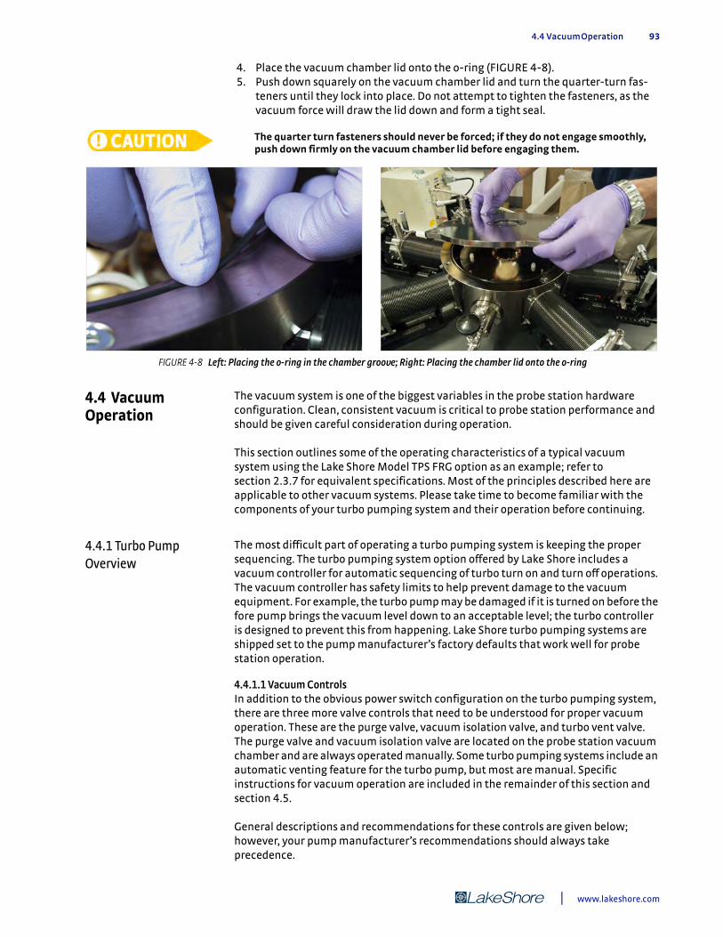
4.4 Vacuum Operation 93
4. Place the vacuum chamber lid onto the o-ring (FIGURE 4-8). 5. Push down squarely on the vacuum chamber lid and turn the quarter-turn fas-
teners until they lock into place. Do not attempt to tighten the fasteners, as the vacuum force will draw the lid down and form a tight seal.
The quarter turn fasteners should never be forced; if they do not engage smoothly, push down firmly on the vacuum chamber lid before engaging them.
4.4 Vacuum Operation
The vacuum system is one of the biggest variables in the probe station hardware configuration. Clean, consistent vacuum is critical to probe station performance and should be given careful consideration during operation.
This section outlines some of the operating characteristics of a typical vacuum system using the Lake Shore Model TPS FRG option as an example; refer to section 2.3.7 for equivalent specifications. Most of the principles described here are applicable to other vacuum systems. Please take time to become familiar with the components of your turbo pumping system and their operation before continuing.
4.4.1 Turbo Pump Overview
The most difficult part of operating a turbo pumping system is keeping the proper sequencing. The turbo pumping system option offered by Lake Shore includes a vacuum controller for automatic sequencing of turbo turn on and turn off operations. The vacuum controller has safety limits to help prevent damage to the vacuum equipment. For example, the turbo pump may be damaged if it is turned on before the fore pump brings the vacuum level down to an acceptable level; the turbo controller is designed to prevent this from happening. Lake Shore turbo pumping systems are shipped set to the pump manufacturer’s factory defaults that work well for probe station operation.
4.4.1.1 Vacuum ControlsIn addition to the obvious power switch configuration on the turbo pumping system, there are three more valve controls that need to be understood for proper vacuum operation. These are the purge valve, vacuum isolation valve, and turbo vent valve. The purge valve and vacuum isolation valve are located on the probe station vacuum chamber and are always operated manually. Some turbo pumping systems include an automatic venting feature for the turbo pump, but most are manual. Specific instructions for vacuum operation are included in the remainder of this section and section 4.5.
General descriptions and recommendations for these controls are given below; however, your pump manufacturer’s recommendations should always take precedence.
FIGURE 4-8 Left: Placing the o-ring in the chamber groove; Right: Placing the chamber lid onto the o-ring
| www.lakeshore.com
94 CHAPTER 4: Basic Operation
D Purge valve: the purge valve shown in FIGURE 4-9 is used to backfill the chamber with dry nitrogen or inert gas. It is most commonly used when warming or venting the system.
D Vacuum isolation valve: the vacuum chamber and turbo pumping system are separated by the vacuum isolation valve located on the probe station. The valve has two potential uses during operation. It can be used to help maintain the cleanest possible vacuum in the chamber as described in section 4.4.1.2 and it allows separation from the pumping system to reduce vibration during cryogenic operation. In the sequence of operations, the vacuum isolation valve can always be opened safely if the vacuum level on each side of the valve is the same.
D Manual turbo vent valve: turbo pump performance relies on precision blades that must be kept in balance at all times. The vent valve on the turbo pump is used to vent the pump system while keeping the blades in balance. The precision blades can be damaged if the pump system is vented through the turbo pump inlet by opening the vacuum isolation valve.
D Automatic turbo vent valve: some turbo pump systems are programmed to automatically vent when they are turned off or lose power. A few seconds after the pumping system is powered off, an automatic valve will backfill room air through the pump, safely venting the pump system and shutting the turbo pump down. However, if the pump vents while the sample cooling assembly is cold, water vapor will condense on it and freeze into damaging ice. It can take approximately a week to return the probe station to proper working order (if this does happen, please refer to section 6.2.12). It is possible that the sample cooling assembly may suffer irreparable damage.
Close the isolation valve when the sample cooling assembly is <77 K to prevent the chamber from being vented if the pump is accidentally turned off or the vacuum pump loses power. Venting the chamber when the sample cooling assembly is cold can damage the probe station.
4.4.1.2 Considerations for Using the Vacuum Isolation ValveOn initial cooldown of the probe station, it is best to close the isolation valve and turn off the vacuum pump when all stages of the sample cooling assembly are less than approximately 77 K. The cooled radiation shields act as a cryopump, creating a better vacuum than the turbo pump. In the case where cryopumping reduces the vacuum pressure in the chamber below that of the turbo pump, it is even possible to draw outside contamination in through the vacuum system. Turning the pump off also minimizes vibration at the sample.
Never operate the probe station above room temperature without the CCR on and the probe station under vacuum.
When operating the sample stage above room temperature, it is best to leave the vacuum isolation valve open and the pump running during operation. This is because at elevated temperatures the system will slowly outgas and degrade the vacuum. The pump line isolation option (PS-PLVI-40) should be used if measurements are routinely made at elevated temperatures to reduce vibrations due to the vacuum pump.
4.4.1.3 Vacuum Gauge LocationFor convenience, the vacuum gauge on the TPS FRG pump option is located on an NW 40 T immediately at the inlet of the turbo pump. Vacuum pressures in the probe station chamber will be a half order of a magnitude higher than measured here. All probe station vacuum specifications are made with the gauge located on the vacuum chamber itself. For more accurate vacuum pressure readings the gauge can be moved to an available port on the vacuum chamber, or the gauge and tee may be moved to between the vacuum isolation valve and vacuum chamber as shown in FIGURE 6-4.
Model CRX-VF Probe Station
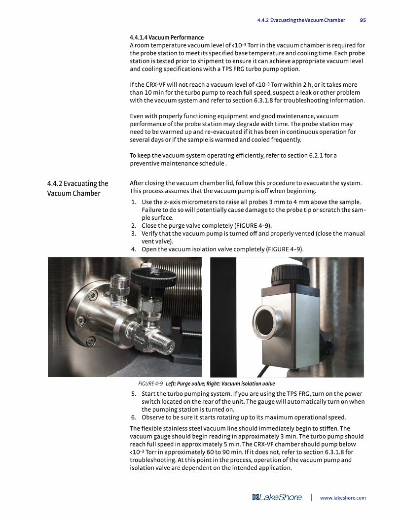
4.4.2 Evacuating the Vacuum Chamber 95
4.4.1.4 Vacuum PerformanceA room temperature vacuum level of <10-3 Torr in the vacuum chamber is required for the probe station to meet its specified base temperature and cooling time. Each probe station is tested prior to shipment to ensure it can achieve appropriate vacuum level and cooling specifications with a TPS FRG turbo pump option.
If the CRX-VF will not reach a vacuum level of <10-3 Torr within 2 h, or it takes more than 10 min for the turbo pump to reach full speed, suspect a leak or other problem with the vacuum system and refer to section 6.3.1.8 for troubleshooting information.
Even with properly functioning equipment and good maintenance, vacuum performance of the probe station may degrade with time. The probe station may need to be warmed up and re-evacuated if it has been in continuous operation for several days or if the sample is warmed and cooled frequently.
To keep the vacuum system operating efficiently, refer to section 6.2.1 for a preventive maintenance schedule .
4.4.2 Evacuating the Vacuum Chamber
After closing the vacuum chamber lid, follow this procedure to evacuate the system. This process assumes that the vacuum pump is off when beginning.
1. Use the z-axis micrometers to raise all probes 3 mm to 4 mm above the sample. Failure to do so will potentially cause damage to the probe tip or scratch the sam-ple surface.
2. Close the purge valve completely (FIGURE 4-9). 3. Verify that the vacuum pump is turned off and properly vented (close the manual
vent valve). 4. Open the vacuum isolation valve completely (FIGURE 4-9).
5. Start the turbo pumping system. If you are using the TPS FRG, turn on the power switch located on the rear of the unit. The gauge will automatically turn on when the pumping station is turned on.
6. Observe to be sure it starts rotating up to its maximum operational speed.
The flexible stainless steel vacuum line should immediately begin to stiffen. The vacuum gauge should begin reading in approximately 3 min. The turbo pump should reach full speed in approximately 5 min. The CRX-VF chamber should pump below <10-3 Torr in approximately 60 to 90 min. If it does not, refer to section 6.3.1.8 for troubleshooting. At this point in the process, operation of the vacuum pump and isolation valve are dependent on the intended application.
FIGURE 4-9 Left: Purge valve; Right: Vacuum isolation valve
| www.lakeshore.com
96 CHAPTER 4: Basic Operation
4.4.3 Shutting Down the Turbo Pump
Follow this procedure to shut down the turbo pumping system. This procedure assumes that the system is sealed and under vacuum.
1. Close the vacuum isolation valve. 2. Turn off the turbo pumping system. If you are using the PS–V81DPC, simply turn
off the main switch on the rear of the unit. 3. Open the manual vent valve located on the side of the turbo pump to vent the
turbo pumping system. In order to increase the lifetime of the turbo pump, it is always recommended to vent the pumping system through the manual vent valve and not simply allow atmospheric air to rush into the inlet.
4. You will hear hissing as the manual vent valve is opened and air rushes into the turbo pump. Once the hissing ceases, completely close the manual vent valve.
Remember you will always need to purge the vacuum chamber and open the vacuum isolation valve before restarting the pump. Never vent the turbo pump through the vacuum isolation valve whether the pump is turned on or turned off. Although this will not immediately destroy the vacuum pump, it will likely stall the pump and decrease its life. Always close the vacuum isolation valve, turn off the pumping system, and open the turbo vent valve if the valve is not configured to open automatically.
4.4.4 Purging the Vacuum Chamber
The purge valve shown in FIGURE 4-9 is used to purge the chamber with dry nitrogen or dry inert gas such as argon. It is most commonly used when warming or venting the system. During warm up, purging with dry gas can speed the warm up process (section 4.5.8, step 6). When opening a system, purging with a dry gas will prevent moisture and contaminants from entering the chamber, which will reduce pump-down time and improve vacuum quality. If available, dry argon is recommended because it is a heavy gas that is easier to evacuate with the turbo vacuum pump.
Follow this procedure to purge the vacuum chamber.
1. Close the vacuum isolation valve and properly shut down the turbo vacuum pump (section 4.4.3).
2. Attach the gas line to the p in NPT purge valve fitting. A p in NPT to p in OD tube adapter is included in the CRX-VF spares kit.
3. Regulate the gas pressure from 6.89 kPa to 13.79 kPa (1 psi to 2 psi). 4. Open the purge valve slowly until it is fully open. In about 1 min the pressure
relief valve on the chamber will open and release gas. 5. Open the vacuum chamber lid for sample exchange with the gas flowing.
The dry gas will prevent moist air from entering the chamber; this will speed vacuum pump down time.
6. Close the purge valve fully when the vacuum chamber lid is replaced.
If the system is accidentally left open for a long period of time, it should be cycle-purged to reduce contamination. Refer to section 5.2.1.1 for this procedure.
The vacuum chamber is not designed for positive pressure and should never be pressurized above 2.1 kPa (0.5 psi). The pressure relief valve on the chamber is set for 2.1 kPa (0.5 psi) and should never be disabled or modified. Failure to comply may result in injury or death.
The vacuum chamber should only be purged with dry nitrogen, dry argon, or inert gas. Failure to comply may result in injury or death or damage to the probe station.
Never purge the chamber with dry nitrogen, dry argon, or inert gas unless all stages and the probe arm sensor are above 100 K.
Model CRX-VF Probe Station

4.5 Temperature Operation 97
Never vent the chamber to atmosphere unless all stages and the probe arm sensor are above 290 K.
4.5 Temperature Operation
This section describes basic temperature operation of the probe station; advanced temperature operation will be discussed in Chapter 5. Before performing any of the operations, the system must be closed and evacuated as described in section 4.4.2. Often, there are multiple ways of performing some of these procedures, but we have chosen steps that represent a good balance between ease of operation and time efficiency.
4.5.1 CRX-VF Cooling Overview
The recommended operation for variable temperature measurements is to allow the entire CRX-VF station to cool to base temperature and then to warm the sample stage to the measurement setpoint. The operational procedures outlined in the following sections allow the magnetic field to be operated while increasing the sample temperature; however, the magnetic field must be turned off to cool the sample back to lower temperatures.
4.5.2 Controls for Temperature Operation
The CRX-VF uses the CCR, four electronic control loops, and the mechanical heatswitch to establish and regulate temperature. This section details the CCR controls first, followed by the electronic controls, and the mechanical heat switch control.
4.5.2.1 CCR ControlsCCR operation is controlled by the switches located on the CCR compressor control panel shown in FIGURE 4-10. The default off settings for the various CCR controls are listed in TABLE 4-1. The compressor supply and return pressures vary according to the heat load presented to the cold head. During operation, typical supply helium gas pressure is between 1.8 MPa and 2.3 MPa (261 to 334 psig). Refer to the SRDK Cryocooler Operation Manual for additional information about admissible operating pressure ranges outside these typical values.
FIGURE 4-10 CCR compressor panel
Switch name CCR off CCR on
Supply pressure1.43 MPa to1.46 MPa at 20 °C(207 psig to 212 psig at 68 °F)
1.8 MPa to 2.3 MPa(261 psig to 334 psig)
Main power On On
CCR On/Off Off On
TABLE 4-1 CCR compressor default off settings
| www.lakeshore.com

98 CHAPTER 4: Basic Operation
4.5.2.2 Electronic Temperature ControlsThe two Model 336 temperature controllers provide the electronic control for the CRX-VF stage temperatures. Each Model 336 has four sensor inputs and four independent control outputs. Only the two PID (proportional, integral, derivative) control outputs of each Model 336 are used in the standard CRX-VF configuration (refer to Chapter 2 of the instrument manuals for details). The top Model 336 provides control of the sample stage, the magnet stage, and monitors the probe arm sensor. The bottom Model 336 monitors the CCR second stage and provides control of the CCR first stage and radiation shield.
Each controlled stage includes a temperature sensor and a heater. The temperature sensor is the control input for each loop, and the heater is the control output for each loop. The controller balances its heater power against the cooling power of the CCR at a desired temperature setpoint. Since the controller cannot contribute cooling power, the setpoint must be higher in temperature than the base temperature of the stage for the controller to operate properly.
If the controller is configured improperly, the controller can provide enough heat to damage the probe station.
The Model 336 controllers are configured at Lake Shore as described in the temperature controller configuration table (TABLE 4-3). However, the settings should be re-verified any time the system is moved, serviced or reconfigured (section 3.8.1.3).
The sample stage is the only stage actively controlled to a temperature setpoint during normal operation. The other control loop setpoints should be set to zero or the heaters should be turned off. The sample stage control operates with different control settings at different temperatures. Nominal values for operation are described in each of the following sections and summarized in the temperature controller configuration table (TABLE 4-3). Some adjustments to these settings will be required during operation. Control of the other three stages is generally limited to warming the system for sample exchange. They are most often operated by turning the heater output on and off.
4.5.2.3 Heat Switch ControlThe manually operated heat switch is controlled by the knob on the front of the probe station (FIGURE 4-11). The heat switch is a variable tension 3-position switch with ten full revolutions of control. A mechanical stop at both ends of the control knob range prevents over-tightening and damage to the heat switch.
FIGURE 4-11 Heat switch control knob
Model CRX-VF Probe Station
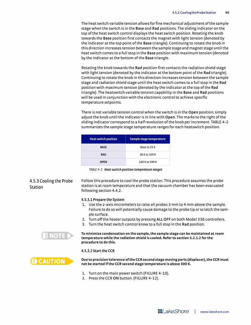
4.5.3 Cooling the Probe Station 99
The heat switch variable tension allows for fine mechanical adjustment of the sample stage when the switch is in the Base and Rad positions. The sliding indicator on the top of the heat switch control displays the heat switch position. Rotating the knob towards the Base position first contacts the magnet with light tension (denoted by the indicator at the top point of the Base triangle). Continuing to rotate the knob in this direction increases tension between the sample stage and magnet stage until the heat switch comes to a full stop in the Base position with maximum tension (denoted by the indicator at the bottom of the Base triangle.
Rotating the knob towards the Rad position first contacts the radiation shield stage with light tension (denoted by the indicator at the bottom point of the Rad triangle). Continuing to rotate the knob in this direction increases tension between the sample stage and radiation shield stage until the heat switch comes to a full stop in the Rad postiion with maximum tension (denoted by the indicator at the top of the Rad triangle). The heatswitch variable tension capability in the Base and Rad positions will be used in conjunction with the electronic control to achieve specific temperature setpoints.
There is not variable tension control when the switch is in the Open position; simply adjust the knob until the indicator is in line with Open. The marks to the right of the sliding indicator correspond to a half revolution of the knob per increment. TABLE 4-2 summarizes the sample stage temperature ranges for each heatswitch position.
4.5.3 Cooling the Probe Station
Follow this procedure to cool the probe station. This procedure assumes the probe station is at room temperature and that the vacuum chamber has been evacuated following section 4.4.2.
4.5.3.1 Prepare the System 1. Use the z-axis micrometers to raise all probes 3 mm to 4 mm above the sample.
Failure to do so will potentially cause damage to the probe tip or scratch the sam-ple surface.
2. Turn off the heater outputs by pressing ALL OFF on both Model 336 controllers. 3. Turn the heat switch control know to a full stop in the Rad position.
To minimize condensation on the sample, the sample stage can be maintained at room temperature while the radiation shield is cooled. Refer to section 5.2.1.2 for the procedure to do this.
4.5.3.2 Start the CCR
Due to precision tolerance of the CCR second stage moving parts (displacer), the CCR must not be started if the CCR second stage temperature is above 300 K.
1. Turn on the main power switch (FIGURE 4-10). 2. Press the CCR ON button. (FIGURE 4-12).
Heat switch position Sample stage temperature
BASE Base to 35 K
RAD 36 K to 100 K
OPEN 100 K to 500 K
TABLE 4-2 Heat switch position temperature ranges
| www.lakeshore.com
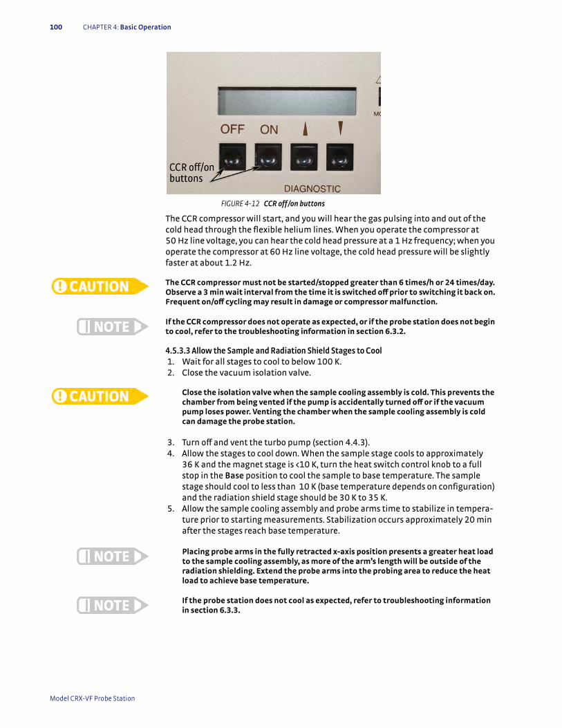
100 CHAPTER 4: Basic Operation
The CCR compressor will start, and you will hear the gas pulsing into and out of the cold head through the flexible helium lines. When you operate the compressor at 50 Hz line voltage, you can hear the cold head pressure at a 1 Hz frequency; when you operate the compressor at 60 Hz line voltage, the cold head pressure will be slightly faster at about 1.2 Hz.
The CCR compressor must not be started/stopped greater than 6 times/h or 24 times/day. Observe a 3 min wait interval from the time it is switched off prior to switching it back on. Frequent on/off cycling may result in damage or compressor malfunction.
If the CCR compressor does not operate as expected, or if the probe station does not begin to cool, refer to the troubleshooting information in section 6.3.2.
4.5.3.3 Allow the Sample and Radiation Shield Stages to Cool 1. Wait for all stages to cool to below 100 K. 2. Close the vacuum isolation valve.
Close the isolation valve when the sample cooling assembly is cold. This prevents the chamber from being vented if the pump is accidentally turned off or if the vacuum pump loses power. Venting the chamber when the sample cooling assembly is cold can damage the probe station.
3. Turn off and vent the turbo pump (section 4.4.3). 4. Allow the stages to cool down. When the sample stage cools to approximately
36 K and the magnet stage is <10 K, turn the heat switch control knob to a full stop in the Base position to cool the sample to base temperature. The sample stage should cool to less than 10 K (base temperature depends on configuration) and the radiation shield stage should be 30 K to 35 K.
5. Allow the sample cooling assembly and probe arms time to stabilize in tempera-ture prior to starting measurements. Stabilization occurs approximately 20 min after the stages reach base temperature.
Placing probe arms in the fully retracted x-axis position presents a greater heat load to the sample cooling assembly, as more of the arm’s length will be outside of the radiation shielding. Extend the probe arms into the probing area to reduce the heat load to achieve base temperature.
If the probe station does not cool as expected, refer to troubleshooting information in section 6.3.3.
FIGURE 4-12 CCR off/on buttons
Model CRX-VF Probe Station
4.5.4 Operating Sample Stage at Base Temperature 101
4.5.4 Operating Sample Stage at Base Temperature
To operate the sample stage at base temperature, the heat switch should be in the full stop (Base) position; no electronic control is required. The base temperature of the sample stage is <10 K, but it does have variability of about ±0.5 K due to surface contact variation in the heat switch seating. To minimize heat load at the sample, turn the microscope light down or off.
Turning the knob harder against the mechanical stop does not improve the base temperature; however, turning the knob counterclockwise a few turns and then moving it back to the base position may improve the base temperature because doing this reseats the switch.
4.5.5 Operating the Sample Stage from Base Temperature to 35 K
When the heat switch is in the Base position, the sample stage is thermally connected to the magnet stage; therefore, adding heat to the sample stage via the electronic heater output will add heat to the magnet stage. To operate the sample stage between base temperature and 35 K, first reduce the heat switch tension on the magnet stage to increase the thermal resistance between the sample stage and magnet stage, and then use the electronic control to set the operating temperature. Adjust the heat switch from full stop in the Base direction for temperatures close to 10 K to two and a half turns in the Rad direction for temperatures close to 35 K.
Follow this procedure to operate the sample stage from base temperature to 35 K. The sample stage is the only stage actively controlled to a temperature setpoint during normal operation. This procedure assumes that you have cooled the probe station to base temperature, the heat switch is at full stop in the Base position, and you wish to bring the sample up to the measurement temperature.
1. Use the z-axis micrometers to raise all probes 3 mm to 4 mm above the sample. Failure to do so will potentially cause damage to the probe tip or scratch the sam-ple surface.
2. Turn the heat switch control knob toward the Rad direction so that the sample stage rises to a few degrees below the desired setpoint. The range of the Base position is approximately 2.5 turns.
Monitor the magnet temperature. If the magnet temperature falls abruptly by 0.1 K to 0.3 K, this signifies that the heat switch is no longer in contact with the magnet stage, and good temperature control will not be possible.
For temperature setpoints in the range 25 K to 35 K, adjusting the heat switch control knob is more challenging. As long as the magnet stage remains <5 K when heater power is applied, precise adjustment of the heat switch is not required. Proceed with steps 3 to 4.
3. On the top Model 336 controller, change the Input A sample stage setpoint to the desired temperature. The magnet and radiation shield stage heaters should remain off.
4. Use the sample stage controller settings given in TABLE 4-5 to set the P, I, and D and the proper heater range settings for the temperature setpoint. The heater will turn on once the range is set.
5. If the magnet temperature rises above 5 K, turn the heat switch control knob in the Rad direction in 1/bg turn increments until the magnet temperature is in the range of <5 K.
The magnet stage must adhere to the limits in TABLE 4-6 when charging the superconducting magnet. Failure to comply will result in a magnet quench. Numerous or severe quenches can damage the magnet.
6. Wait for the sample stage temperature to stabilize. 7. Adjust the P, I, and D settings as necessary to improve stability.
| www.lakeshore.com

102 CHAPTER 4: Basic Operation
4.5.6 Operating the Sample Stage from 36 K to 100 K
For operation from 36 K to 100 K, the heat switch is moved to the Rad position where the sample stage is thermally connected to the radiation shield stage; therefore, adding heat to the sample stage via the electronic heater output will add heat to the radiation shield stage. To operate the sample stage between 36 K and 100 K, you will first reduce the heat switch tension on the radiation shield stage to increase the thermal resistance between the sample stage and radiation shield stage prior to using the electronic control to set the operating temperature. The heat switch will be adjusted from full stop in the Rad direction (for temperatures close to 36 K) to 2.5 turns in the Base direction (for temperatures close to 100 K).
Follow this procedure to operate the sample stage from 36 K to 100 K. The sample stage is the only stage actively controlled to a temperature setpoint during normal operation. The magnet and radiation shield stages will remain close to their base temperature even with the sample at elevated temperatures. We recommend operating the turbo vacuum pump to maintain proper vacuum in the chamber any time the sample stage is above 77 K. This procedure assumes that the heat switch is in the Base position and that you wish to bring the sample up to the measurement temperature.
1. Use the z-axis micrometers to raise all probes 3 mm to 4 mm above the sample. Failure to do so will potentially cause damage to the probe tip or scratch the sam-ple surface.
2. Turn the heat switch control knob in the Rad direction until it reaches full stop at the Rad position to establish a baseline temperature at approximately 30 K to 35 K.
The temperature of the magnet stage will drop as the heat load is removed. The heat switch may be safely moved from BASE position to RAD or OPEN positions with the magnet energized.
Do not move the heat switch from the RAD or OPEN positions to the BASE position with the magnet energized. Failure to comply will result in a magnet quench. Numerous or severe quenches can damage the magnet.
3. Turn the heat switch control knob in the Base direction so that the sample stage rises to a temperature below the desired setpoint. The range of the Rad position is ~2.5 turns.
4. On the top Model 336 controller, change the Input A sample stage setpoint to the desired temperature. The magnet and radiation shield stage heaters should remain off.
5. Use the sample stage controller settings given in TABLE 4-5 to set the P, I, and D and the proper heater range settings for the temperature setpoint. The heater will turn on once the range is set.
6. If the magnet temperature rises above 5.5 K, turn the heat switch control knob in the BASE direction in 1/bg turn increments until the magnet temperature is in the range of <5.5 K
The magnet stage must adhere to the limits in TABLE 4-6 when charging the superconducting magnet. Failure to comply will result in a magnet quench. Numerous or severe quenches can damage the magnet.
7. Wait for the sample stage temperature to stabilize. 8. Adjust the P, I, and D settings as necessary to improve stability.
Optional: If the sample stage temperature rises above 77 K during operation, turn on the turbo vacuum pump using this procedure:
Model CRX-VF Probe Station
4.5.7 Operating the Sample Stage From 100 K to 500 K 103
a. Start the turbo vacuum pump as described in section 4.4.2, steps 5 and 6. b. Once the turbo vacuum pump is operating at full speed, slowly open the
vacuum isolation valve until it is fully open.
Do not open the vacuum isolation valve until the turbo vacuum pump is operating at full speed.
If the sample stage falls below 77 K during operation, turn off the turbo vacuum pump using this procedure.
a. Fully close the vacuum isolation valve. b. Turn off and vent the turbo vacuum pump (section 4.4.3).
4.5.7 Operating the Sample Stage From 100 K to 500 K
For operation from 100 K to 500 K, the heat switch is moved to the Open position where the sample stage is thermally isolated from both the magnet stage and the radiation shield stage. When the heat switch is in the Open position, the sample stage is cooled through a large thermal resistance to the radiation shield stage. The heat switch is set at the midpoint of its travel (five turns from either full stop position). Over this entire operating temperature range no fine adjustment of the heat switch is required.
Follow this procedure to operate the sample stage from 100 K to 500 K. The sample stage is the only stage actively controlled to a temperature setpoint during normal operation. The magnet and radiation shield stages will remain close to their base temperature even with the sample at elevated temperatures. We recommend operating the turbo vacuum pump to maintain proper vacuum in the chamber any time the sample stage is above 77 K. This procedure assumes the heat switch is in the Rad position and you wish to bring the sample up to the measurement temperature.
1. Use the z-axis micrometers to raise all probes 3 mm to 4 mm above the sample. Failure to do so will potentially cause damage to the probe tip or scratch the sam-ple surface.
2. Turn the heat switch control knob to align the heat switch indicator to the Open position.
The heat switch may be safely moved from RAD to OPEN positions with the magnet energized.
The heat switch may never be moved from the RAD or OPEN positions to the BASE position with the magnet energized. Failure to comply will result in a magnet quench. Numerous or severe quenches can damage the magnet.
3. On the top Model 336 controller, change the Input A sample stage setpoint to the desired temperature. The radiation shield stage heater should remain off.
4. Use the sample stage controller settings given in TABLE 4-3 to set the P, I, and D and the proper heater range settings for the temperature setpoint. The heater will turn on once the range is set.
5. Wait for the sample stage temperature to stabilize. 6. Adjust the P, I, and D settings as necessary to improve stability.
The magnet stage must adhere to the limits in TABLE 4-6 when charging the superconducting magnet. Failure to comply will result in a magnet quench. Numerous or severe quenches can damage the magnet.
If the sample stage temperature sensor exceeds 500 K causing the Input A of the top Model 336 to read “TOVER,” the sample stage control output will be disengaged. This is to prevent a runaway temperature condition. Simply wait for the temperature to fall back into the sensor range to proceed. Adjust the control parameters to prevent the temperature overshoot.
| www.lakeshore.com
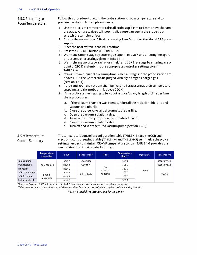
104 CHAPTER 4: Basic Operation
4.5.8 Returning to Room Temperature
Follow this procedure to return the probe station to room temperature and to prepare the station for sample exchange.
1. Use the z-axis micrometers to raise all probes up 3 mm to 4 mm above the sam-ple stage. Failure to do so will potentially cause damage to the probe tip or scratch the sample surface.
2. Ensure the magnet is at 0 field by pressing Zero Output on the Model 625 power supply.
3. Place the heat switch in the RAD position. 4. Press the CCR OFF button (FIGURE 4-12). 5. Warm the sample stage by entering a setpoint of 290 K and entering the appro-
priate controller settings given in TABLE 4-4. 6. Warm the magnet stage, radiation shield, and CCR first stage by entering a set-
point of 290 K and entering the appropriate controller settings given in TABLE 4-4.
7. Optional: to minimize the warmup time, when all stages in the probe station are above 100 K the system can be purged with dry nitrogen or argon gas (section 4.4.4).
8. Purge and open the vacuum chamber when all stages are at their temperature setpoints and the probe arm is above 290 K.
9. If the probe station is going to be out of service for any length of time perform these procedures:
a. If the vacuum chamber was opened, reinstall the radiation shield lid and vacuum chamber lid.
b. Close the purge valve and disconnect the gas line. c. Open the vacuum isolation valve. d. Turn on the turbo pump for approximately 15 min. e. Close the vacuum isolation valve. f. Turn off and vent the turbo vacuum pump (section 4.4.3).
4.5.9 Temperature Control Summary
The temperature controller configuration table (TABLE 4-3) and the CCR and electronic control settings table (TABLE 4-4 and TABLE 4-5) summarize the typical settings needed to maintain CRX-VF temperature control. TABLE 4-6 provides the sample stage electronic control settings.
Temperature controller
Input Sensor type* FilterTemperature
limit**Input units Sensor curve
Sample stage
Top Model 336
Input A GaAs diode
On (8 pts 10% window)
505 K
Kelvin
User curve 21
Magnet stage Input B Cernox™ 305 K User curve 22
Probe arm Input C
Silicon diode
360 K
DT-670CCR second stage
Bottom Model 336
Input A 305 K
CCR first stage Input B 305 K
Radiation shield Input C 360 K
*Range for Si diode is 2.5 V with diode current 10 μA. For platinum sensors, autorange and current reversal are on**Controller maximum temperature limit set above operational maximum to avoid nuisance system shutdown during operation
TABLE 4-3 Model 336 input settings for the CRX-VF
Model CRX-VF Probe Station
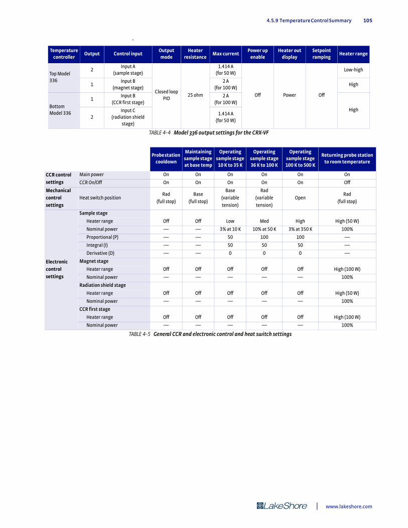
4.5.9 Temperature Control Summary 105
.
Temperature controller
Output Control inputOutput mode
Heater resistance
Max currentPower up
enableHeater out
displaySetpoint ramping
Heater range
Top Model 336
2Input A
(sample stage)
Closed loop PID
25 ohm
1.414 A(for 50 W)
Off Power Off
Low-high
1Input B
(magnet stage)2 A
(for 100 W)High
Bottom Model 336
1Input B
(CCR first stage)2 A
(for 100 W)
High
2Input C
(radiation shield stage)
1.414 A(for 50 W)
TABLE 4-4 Model 336 output settings for the CRX-VF
Probe station cooldown
Maintaining sample stage at base temp
Operating sample stage
10 K to 35 K
Operating sample stage 36 K to 100 K
Operating sample stage 100 K to 500 K
Returning probe station to room temperature
CCR control settings
Main power On On On On On On
CCR On/Off On On On On On Off
Mechanical control settings
Heat switch positionRad
(full stop)
Base
(full stop)
Base
(variable
tension)
Rad
(variable
tension)
OpenRad
(full stop)
Electronic control settings
Sample stage
Heater range Off Off Low Med High High (50 W)
Nominal power — — 3% at 10 K 10% at 50 K 3% at 350 K 100%
Proportional (P) — — 50 100 100 —
Integral (I) — — 50 50 50 —
Derivative (D) — — 0 0 0 —
Magnet stage
Heater range Off Off Off Off Off High (100 W)
Nominal power — — — — — 100%
Radiation shield stage
Heater range Off Off Off Off Off High (50 W)
Nominal power — — — — — 100%
CCR first stage
Heater range Off Off Off Off Off High (100 W)
Nominal power — — — — — 100%
TABLE 4-5 General CCR and electronic control and heat switch settings
| www.lakeshore.com
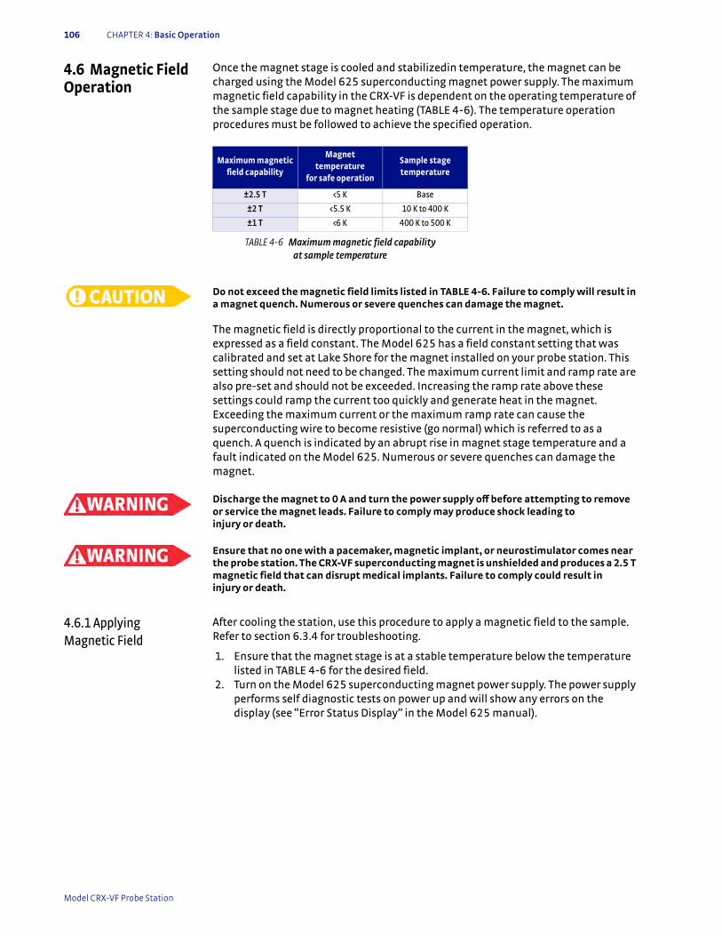
106 CHAPTER 4: Basic Operation
4.6 Magnetic Field Operation
Once the magnet stage is cooled and stabilizedin temperature, the magnet can be charged using the Model 625 superconducting magnet power supply. The maximum magnetic field capability in the CRX-VF is dependent on the operating temperature of the sample stage due to magnet heating (TABLE 4-6). The temperature operation procedures must be followed to achieve the specified operation.
Do not exceed the magnetic field limits listed in TABLE 4-6. Failure to comply will result in a magnet quench. Numerous or severe quenches can damage the magnet.
The magnetic field is directly proportional to the current in the magnet, which is expressed as a field constant. The Model 625 has a field constant setting that was calibrated and set at Lake Shore for the magnet installed on your probe station. This setting should not need to be changed. The maximum current limit and ramp rate are also pre-set and should not be exceeded. Increasing the ramp rate above these settings could ramp the current too quickly and generate heat in the magnet. Exceeding the maximum current or the maximum ramp rate can cause the superconducting wire to become resistive (go normal) which is referred to as a quench. A quench is indicated by an abrupt rise in magnet stage temperature and a fault indicated on the Model 625. Numerous or severe quenches can damage the magnet.
Discharge the magnet to 0 A and turn the power supply off before attempting to remove or service the magnet leads. Failure to comply may produce shock leading to injury or death.
Ensure that no one with a pacemaker, magnetic implant, or neurostimulator comes near the probe station. The CRX-VF superconducting magnet is unshielded and produces a 2.5 T magnetic field that can disrupt medical implants. Failure to comply could result in injury or death.
4.6.1 Applying Magnetic Field
After cooling the station, use this procedure to apply a magnetic field to the sample. Refer to section 6.3.4 for troubleshooting.
1. Ensure that the magnet stage is at a stable temperature below the temperature listed in TABLE 4-6 for the desired field.
2. Turn on the Model 625 superconducting magnet power supply. The power supply performs self diagnostic tests on power up and will show any errors on the display (see “Error Status Display” in the Model 625 manual).
Maximum magnetic field capability
Magnet temperature
for safe operation
Sample stage temperature
±2.5 T <5 K Base
±2 T <5.5 K 10 K to 400 K
±1 T <6 K 400 K to 500 K
TABLE 4-6 Maximum magnetic field capability at sample temperature
Model CRX-VF Probe Station
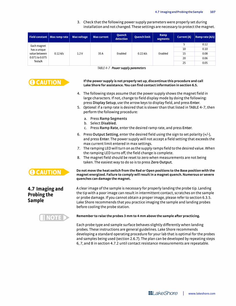
4.7 Imaging and Probing the Sample 107
3. Check that the following power supply parameters were properly set during installation and not changed. These settings are necessary to protect the magnet.
If the power supply is not properly set up, discontinue this procedure and call Lake Shore for assistance. You can find contact information in section 6.5.
4. The following steps assume that the power supply shows the magnet field in large characters. If not, change to field display mode by doing the following:press Display Setup, use the arrow keys to display field, and press Enter.
5. Optional: if a ramp rate is desired that is slower than that listed in TABLE 4-7, then perform the following procedure:
a. Press Ramp Segments b. Select Disabled. c. Press Ramp Rate, enter the desired ramp rate, and press Enter.
6. Press Output Setting, enter the desired field using the sign to set polarity (+/-), and press Enter. The power supply will not accept a field setting that exceeds the max current limit entered in max settings.
7. The ramping LED will turn on as the supply ramps field to the desired value. When the ramping LED turns off, the field change is complete.
8. The magnet field should be reset to zero when measurements are not being taken. The easiest way to do so is to press Zero Output.
Do not move the heat switch from the Rad or Open positions to the Base position with the magnet energized. Failure to comply will result in a magnet quench. Numerous or severe quenches can damage the magnet.
4.7 Imaging and Probing the Sample
A clear image of the sample is necessary for properly landing the probe tip. Landing the tip with a poor image can result in intermittent contact, scratches on the sample or probe damage. If you cannot obtain a proper image, please refer to section 6.3.5. Lake Shore recommends that you practice imaging the sample and landing probes before cooling the probe station.
Remember to raise the probes 3 mm to 4 mm above the sample after practicing.
Each probe type and sample surface behaves slightly differently when landing probes. These instructions are general guidelines. Lake Shore recommends developing a standard operating procedure for your lab that is optimal for the probes and samples being used (section 2.6.7). The plan can be developed by repeating steps 6, 7, and 8 in section 4.7.2 until contact resistance measurements are repeatable.
Field constant Max ramp rate Max voltage Max currentQuench
detectionQuench limit
Ramp segments
Current (A) Ramp rate (A/s)
Each magnet has a unique
value between 0.071 to 0.075
Tesla/A
0.12 A/s 1.2 V 35 A Enabled 0.22 A/s Enabled
5 0.12
10 0.10
15 0.08
20 0.06
25 0.05
TABLE 4-7 Power supply parameters
| www.lakeshore.com
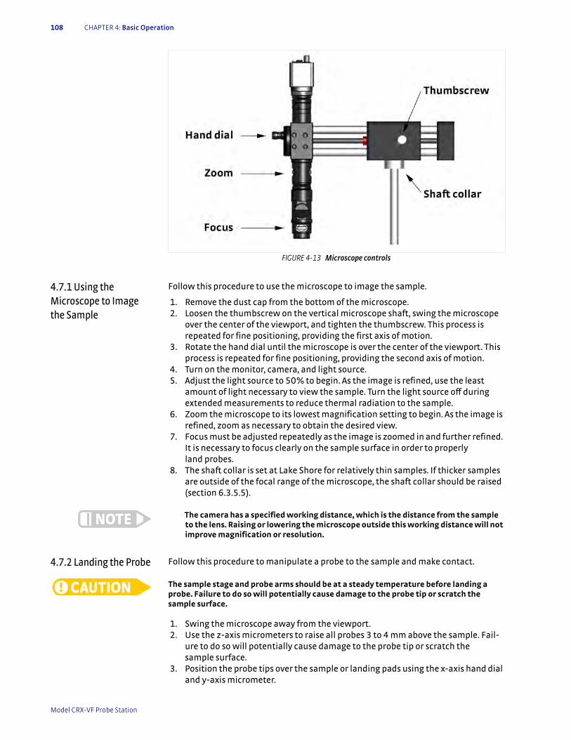
108 CHAPTER 4: Basic Operation
4.7.1 Using the Microscope to Image the Sample
Follow this procedure to use the microscope to image the sample.
1. Remove the dust cap from the bottom of the microscope. 2. Loosen the thumbscrew on the vertical microscope shaft, swing the microscope
over the center of the viewport, and tighten the thumbscrew. This process is repeated for fine positioning, providing the first axis of motion.
3. Rotate the hand dial until the microscope is over the center of the viewport. This process is repeated for fine positioning, providing the second axis of motion.
4. Turn on the monitor, camera, and light source. 5. Adjust the light source to 50% to begin. As the image is refined, use the least
amount of light necessary to view the sample. Turn the light source off during extended measurements to reduce thermal radiation to the sample.
6. Zoom the microscope to its lowest magnification setting to begin. As the image is refined, zoom as necessary to obtain the desired view.
7. Focus must be adjusted repeatedly as the image is zoomed in and further refined. It is necessary to focus clearly on the sample surface in order to properly land probes.
8. The shaft collar is set at Lake Shore for relatively thin samples. If thicker samples are outside of the focal range of the microscope, the shaft collar should be raised (section 6.3.5.5).
The camera has a specified working distance, which is the distance from the sample to the lens. Raising or lowering the microscope outside this working distance will not improve magnification or resolution.
4.7.2 Landing the Probe Follow this procedure to manipulate a probe to the sample and make contact.
The sample stage and probe arms should be at a steady temperature before landing a probe. Failure to do so will potentially cause damage to the probe tip or scratch the sample surface.
1. Swing the microscope away from the viewport. 2. Use the z-axis micrometers to raise all probes 3 to 4 mm above the sample. Fail-
ure to do so will potentially cause damage to the probe tip or scratch the sample surface.
3. Position the probe tips over the sample or landing pads using the x-axis hand dial and y-axis micrometer.
FIGURE 4-13 Microscope controls
Model CRX-VF Probe Station
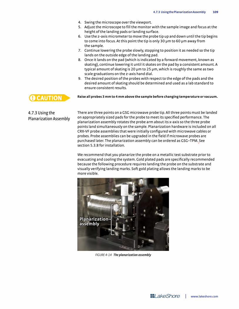
4.7.3 Using the Planarization Assembly 109
4. Swing the microscope over the viewport. 5. Adjust the microscope to fill the monitor with the sample image and focus at the
height of the landing pads or landing surface. 6. Use the z-axis micrometer to move the probe tip up and down until the tip begins
to come into focus. At this point the tip is only 30 µm to 60 µm away from the sample.
7. Continue lowering the probe slowly, stopping to position it as needed so the tip lands on the outside edge of the landing pad.
8. Once it lands on the pad (which is indicated by a forward movement, known as skating), continue lowering it until it skates on the pad by a consistent amount. A typical amount of skating is 20 µm to 25 µm, which is roughly the same as two scale graduations on the z-axis hand dial.
9. The desired position of the probes with respect to the edge of the pads and the desired amount of skating should be determined and used as a lab standard to ensure consistent results.
Raise all probes 3 mm to 4 mm above the sample before changing temperature or vacuum.
4.7.3 Using the Planarization Assembly
There are three points on a GSG microwave probe tip. All three points must be landed on appropriately sized pads for the probe to meet its specified performance. The planarization assembly rotates the probe arm about its x-axis so the three probe points land simultaneously on the sample. Planarization hardware is included on all CRX-VF probe assemblies that were initially configured with microwave cables or probes. Probe assemblies can be upgraded in the field if microwave probes are purchased later. The planarization assembly can be ordered as GSG–TPM. See section 5.3.8 for installation.
We recommend that you planarize the probe on a metallic test substrate prior to evacuating and cooling the system. Gold plated pads are specifically recommended because the following procedure requires landing the probe on the substrate and visually verifying landing marks. Soft gold plating allows the landing marks to be more visible.
FIGURE 4-14 The planarization assembly
| www.lakeshore.com
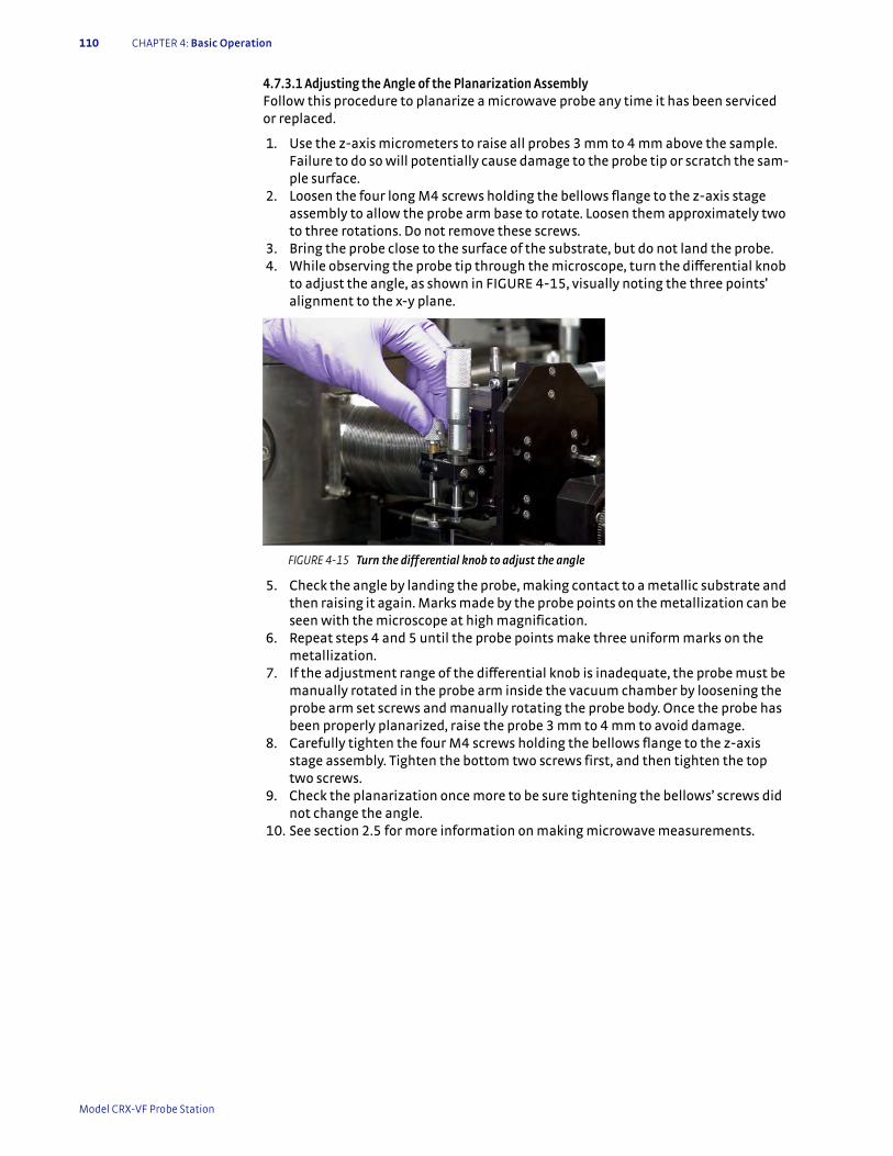
110 CHAPTER 4: Basic Operation
4.7.3.1 Adjusting the Angle of the Planarization AssemblyFollow this procedure to planarize a microwave probe any time it has been serviced or replaced.
1. Use the z-axis micrometers to raise all probes 3 mm to 4 mm above the sample. Failure to do so will potentially cause damage to the probe tip or scratch the sam-ple surface.
2. Loosen the four long M4 screws holding the bellows flange to the z-axis stage assembly to allow the probe arm base to rotate. Loosen them approximately two to three rotations. Do not remove these screws.
3. Bring the probe close to the surface of the substrate, but do not land the probe. 4. While observing the probe tip through the microscope, turn the differential knob
to adjust the angle, as shown in FIGURE 4-15, visually noting the three points’ alignment to the x-y plane.
5. Check the angle by landing the probe, making contact to a metallic substrate and then raising it again. Marks made by the probe points on the metallization can be seen with the microscope at high magnification.
6. Repeat steps 4 and 5 until the probe points make three uniform marks on the metallization.
7. If the adjustment range of the differential knob is inadequate, the probe must be manually rotated in the probe arm inside the vacuum chamber by loosening the probe arm set screws and manually rotating the probe body. Once the probe has been properly planarized, raise the probe 3 mm to 4 mm to avoid damage.
8. Carefully tighten the four M4 screws holding the bellows flange to the z-axis stage assembly. Tighten the bottom two screws first, and then tighten the top two screws.
9. Check the planarization once more to be sure tightening the bellows’ screws did not change the angle.
10. See section 2.5 for more information on making microwave measurements.
FIGURE 4-15 Turn the differential knob to adjust the angle
Model CRX-VF Probe Station
5.1 General 111
Chapter 5: Advanced Operation
5.1 General This chapter is separated into two parts. Section 5.2 provides advanced operation procedures, building on the knowledge and experience gained performing those operations explained in Chapter 4. Section 5.3 explains reconfiguration procedures that are not typically performed on a day-to-day basis, but which are nonetheless essential to know.
5.2 Advanced Temperature Operation
The material in this chapter is written assuming that the user is an experienced oper-ator of the CRX-VF and understands the theory and operation of the CRX-VF as dis-cussed in Chapter 4.
5.2.1 Reducing Condensation on the Sample
Even when following good vacuum practices with well maintained equipment, a small amount of residual gas remains in the vacuum chamber after it is evacuated. The residual gas consists primarily of nitrogen and water vapor. It is generally of little concern because it is cryopumped onto the refrigerator when it is cooled. However, problems may occur with some materials if the residual gas condenses on the sample surface.
5.2.1.1 Heated Cycle PurgeOn some vacuum systems, vacuum base pressure can be improved through a “bake out” process to increase the energy in contaminant molecules so they move away from the surfaces and can be pumped out more quickly. The CRX-VF cannot be baked out, because its components will not tolerate the high temperatures required; how-ever, controlled warming and cycle purging can improve vacuum integrity.
The following procedure can be performed with the sample already in the probe station, as long as the sample will not be affected by the elevated temperature or the gas used.
Follow this procedure to cycle purge the vacuum chamber: 1. Evacuate the chamber as described in section 4.4.2. 2. Warm the refrigerator stages above room temperature; set the setpoints of all
stages to 300 K. 3. Repeat steps a to f three to five times or as needed. Note the reading on the vac-
uum gauge at the end of each cycle; the base pressure should improve with each cycle. Typically after three to five cycles only marginal improvement in base pres-sure is achieved and the process can be stopped.
a. Allow the vacuum pump to run for 30 min to 60 min, and record the base pressure gauge reading.
b. Close the vacuum isolation valve, and shut down and vent the turbo pumping system.
c. Purge the vacuum chamber with dry argon following steps 2 to 4 in section 4.4.4. Close the purge valve as soon as the pressure relief valve opens.
d. Allow the dry gas to remain in the chamber for 30 min to 60 min. The heated stages will warm the dry gas and internal surfaces of the probe station.
e. Open the vacuum isolation valve. f. Start the turbo pumping system to evacuate the chamber.
4. Turn all heaters off.
| www.lakeshore.com
112 CHAPTER 5: Advanced Operation
If the sample is already in place, proceed with temperature operation. If the system is to be opened for sample exchange, close the vacuum isolation valve, turn off and properly vent the turbo pumping system, and follow steps 4 to 6 of section 4.4.4.
5.2.1.2 Maintaining the Sample at Room Temperature While Cooling the Probe StationThe following procedure is a simple but effective way to minimize the condensation on the sample. This is accomplished by cooling the radiation shield stage first so that the majority of residual gas is attracted to it and not the sample.
Follow this procedure to reduce condensation on the sample: 1. Evacuate the chamber as described in section 4.4.2 or perform a heated cycle
purge as described in section 5.2.1.1. 2. Place the heatswitch in the Open position. 3. Control the sample stage at 300 K using control settings in TABLE 4-3 and
TABLE 4-4 (Output 2 on the top Model 336). 4. Cool the refrigerator by following the instructions in section 4.5.3. The tempera-
ture controller will keep the sample stage warm while the remainder of the probe station cools to base temperature. At this point, any residual gas in the chamber will condense on the magnet and radiation shield stages.
5. When the radiation shield stage is cooled to less than 70 K, turn off the sample stage heater by pressing ALL OFF on the top Model 336, and close the heatswitch to the Rad position.
6. Allow the sample stage to cool. 7. Operate the probe station normally.
5.2.2 Operation for Minimum Probe Temperature
The standard configuration for the probe thermal anchor point is to the radiation shield which cools the probes to <50 K. This thermal anchor location keeps the heat load of the probe arms from reaching the magnet stage. For measurements at base temperature where the probes need to be cooled to <20 K, the probe thermal anchor point may be attached to the locations on the magnet stage shown in FIGURE 5-1. In this configuration, the magnet may be operated to full field at base temperature; however, magnetic field operation is derated at elevated temperatures where the additional heat load may cause the magnet to quench. The operational limits for this configuration are listed in TABLE 5-1
Do not exceed the magnetic field limits listed in TABLE 5-1 with the probe thermal anchors attached to the magnet stage. Failure to comply will result in a magnet quench. Numerous or severe quenches can damage the magnet.
5.3 Probe Arm Assembly Reconfiguration
The following sections describe the procedures to reconfigure the probe arm assem-blies of your probe station. These reconfigurations will not necessarily need to be done daily, but you may find them essential for some research situations.
Maximum magnetic field capability
Magnet temperature for safe operation
Sample stage temperature
±2.5 T <5.5 K Base
±2 T <5.5 K 10 K to 400 K
±1 T <6 K 400 K to 500 K
TABLE 5-1 Maximum magnetic field capability at sample temperature with probe thermal anchors attached to the magnet stage
Model CRX-VF Probe Station
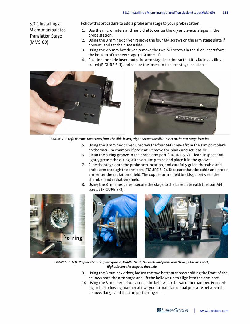
5.3.1 Installing a Micro-manipulated Translation Stage (MMS-09) 113
5.3.1 Installing a Micro-manipulated Translation Stage (MMS-09)
Follow this procedure to add a probe arm stage to your probe station.
1. Use the micrometers and hand dial to center the x, y and z-axis stages in the probe station.
2. Using the 3 mm hex driver, remove the four M4 screws on the arm stage plate if present, and set the plate aside.
3. Using the 2.5 mm hex driver, remove the two M3 screws in the slide insert from the bottom of the new stage (FIGURE 5-1).
4. Position the slide insert onto the arm stage location so that it is facing as illus-trated (FIGURE 5-1) and secure the insert to the arm stage location.
5. Using the 3 mm hex driver, unscrew the four M4 screws from the arm port blank on the vacuum chamber if present. Remove the blank and set it aside.
6. Clean the o-ring groove in the probe arm port (FIGURE 5-2). Clean, inspect and lightly grease the o-ring with vacuum grease and place it in the groove.
7. Slide the stage onto the probe arm location, and carefully guide the cable and probe arm through the arm port (FIGURE 5-2). Take care that the cable and probe arm enter the radiation shield. The copper arm shield braids go between the chamber and radiation shield.
8. Using the 3 mm hex driver, secure the stage to the baseplate with the four M4 screws (FIGURE 5-2).
9. Using the 3 mm hex driver, loosen the two bottom screws holding the front of the bellows onto the arm stage and lift the bellows up to align it to the arm port.
10. Using the 3 mm hex driver, attach the bellows to the vacuum chamber. Proceed-ing in the following manner allows you to maintain equal pressure between the bellows flange and the arm port o-ring seal.
FIGURE 5-1 Left: Remove the screws from the slide insert; Right: Secure the slide insert to the arm stage location
FIGURE 5-2 Left: Prepare the o-ring and groove; Middle: Guide the cable and probe arm through the arm port; Right: Secure the stage to the table
| www.lakeshore.com
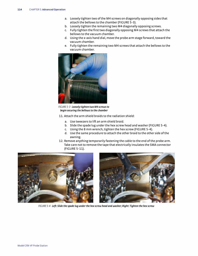
114 CHAPTER 5: Advanced Operation
a. Loosely tighten two of the M4 screws on diagonally opposing sides that attach the bellows to the chamber (FIGURE 5-3).
b. Loosely tighten the remaining two M4 diagonally opposing screws. c. Fully tighten the first two diagonally opposing M4 screws that attach the
bellows to the vacuum chamber. d. Using the x-axis hand dial, move the probe arm stage forward, toward the
vacuum chamber. e. Fully tighten the remaining two M4 screws that attach the bellows to the
vacuum chamber.
11. Attach the arm shield braids to the radiation shield:
a. Use tweezers to lift an arm shield braid. b. Slide the spade lug under the hex screw head and washer (FIGURE 5-4). c. Using the 8 mm wrench, tighten the hex screw (FIGURE 5-4). d. Use the same procedure to attach the other braid to the other side of the
awning. 12. Remove anything temporarily fastening the cable to the end of the probe arm.
Take care not to remove the tape that electrically insulates the SMA connector (FIGURE 5-11).
FIGURE 5-3 Loosely tighten two M4 screws to begin securing the bellows to the chamber
FIGURE 5-4 Left: Slide the spade lug under the hex screw head and washer; Right: Tighten the hex screw
Model CRX-VF Probe Station
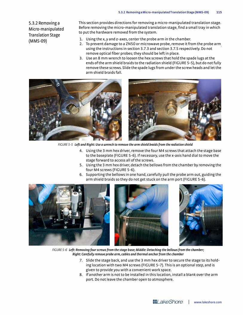
5.3.2 Removing a Micro-manipulated Translation Stage (MMS-09) 115
5.3.2 Removing a Micro-manipulated Translation Stage (MMS-09)
This section provides directions for removing a micro-manipulated translation stage. Before removing the micro-manipulated translation stage, find a small tray in which to put the hardware removed from the system.
1. Using the x, y and z-axes, center the probe arm in the chamber. 2. To prevent damage to a ZN50 or microwave probe, remove it from the probe arm
using the instructions in section 3.7.3 and section 3.7.5 respectively. Do not remove optical fiber probes; they should be left in place.
3. Use an 8 mm wrench to loosen the hex screws that hold the spade lugs at the ends of the arm shield braids to the radiation shield (FIGURE 5-5), but do not fully remove these screws. Slide the spade lugs from under the screw heads and let the arm shield braids fall.
4. Using the 3 mm hex driver, remove the four M4 screws that attach the stage base to the baseplate (FIGURE 5-6). If necessary, use the x-axis hand dial to move the stage forward to access all of the screws.
5. Using the 3 mm hex driver, detach the bellows from the chamber by removing the four M4 screws (FIGURE 5-6).
6. Supporting the bellows in one hand, carefully pull the probe arm out, guiding the arm shield braids so they do not get stuck on the arm port (FIGURE 5-6).
7. Slide the stage back, and use the 3 mm hex driver to secure the stage to its hold-ing location with two M4 screws (FIGURE 5-7). This is an optional step, and is given to provide you with a convenient work space.
8. If another arm is not to be installed in this location, install a blank over the arm port. Do not leave the chamber open to atmosphere.
FIGURE 5-5 Left and Right: Use a wrench to remove the arm shield braids from the radiation shield
FIGURE 5-6 Left: Removing four screws from the stage base; Middle: Detaching the bellows from the chamber; Right: Carefully remove probe arm, cables and thermal anchor from the chamber
| www.lakeshore.com

116 CHAPTER 5: Advanced Operation
5.3.3 Removing a Probe Arm and Base
This procedure assumes that you have removed the micro-manipulated stage and secured the stage to its holding location as directed in section 5.3.2. Follow this pro-cedure to remove a probe arm and base.
1. Using the 3 mm hex driver, loosen and remove the four long M4 horizontal screws that attach the bellows to the z-axis stage (FIGURE 5-8).
2. Grasp the square end flange of the bellows, and with a twisting motion, work the bellows end flange off the probe arm base. This should be done slowly and with a great deal of control.
3. Compress the bellows to make room to slide it carefully off the probe arm. When you reach the end of the probe arm, you will need to tilt it up to remove it from the probe arm (FIGURE 5-8). Place the bellows on a clean, lint-free cloth or wipe.
4. If you do not have a planarization assembly, loosen the M4 screw that holds the stabilization bracket to the probe arm base.
5. If you have a planarization assembly attached to the probe arm, loosen the two M3 screws that hold the planarization assembly to the arm base. You may need to turn the z-axis micrometer to access the screw that is behind the micrometer (FIGURE 5-9). The planarization assembly will remain attached to the stage.
FIGURE 5-7 Secure the micro-manipulated stage to its holding location
FIGURE 5-8 Left: Remove the four horizontal screws that attach the bellows to the z-axis stage; Right: Compress the bellows to remove it from the probe arm
Model CRX-VF Probe Station
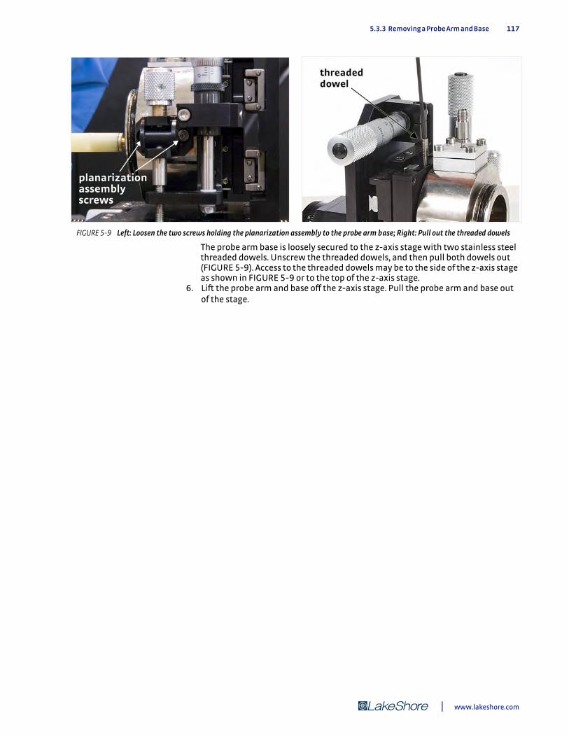
5.3.3 Removing a Probe Arm and Base 117
The probe arm base is loosely secured to the z-axis stage with two stainless steel threaded dowels. Unscrew the threaded dowels, and then pull both dowels out (FIGURE 5-9). Access to the threaded dowels may be to the side of the z-axis stage as shown in FIGURE 5-9 or to the top of the z-axis stage.
6. Lift the probe arm and base off the z-axis stage. Pull the probe arm and base out of the stage.
FIGURE 5-9 Left: Loosen the two screws holding the planarization assembly to the probe arm base; Right: Pull out the threaded dowels
| www.lakeshore.com
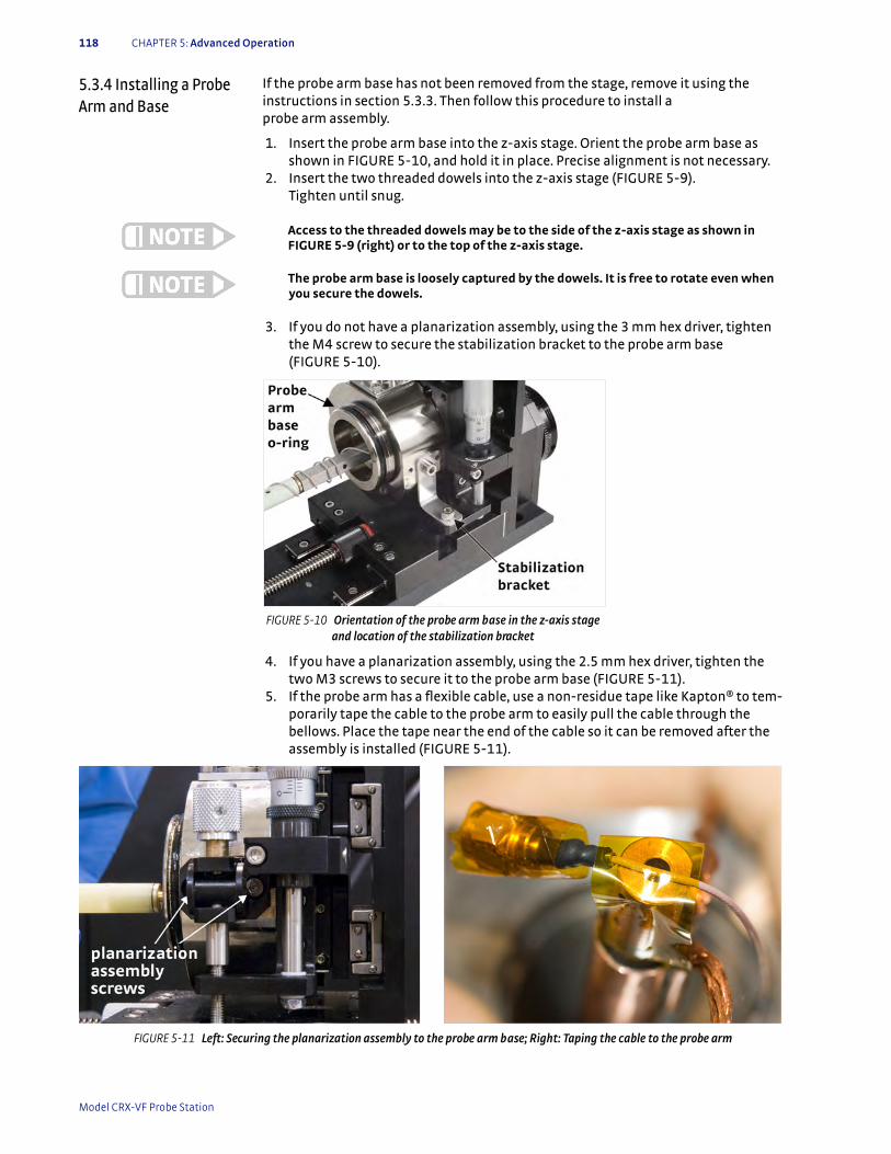
118 CHAPTER 5: Advanced Operation
5.3.4 Installing a Probe Arm and Base
If the probe arm base has not been removed from the stage, remove it using the instructions in section 5.3.3. Then follow this procedure to install a probe arm assembly.
1. Insert the probe arm base into the z-axis stage. Orient the probe arm base as shown in FIGURE 5-10, and hold it in place. Precise alignment is not necessary.
2. Insert the two threaded dowels into the z-axis stage (FIGURE 5-9). Tighten until snug.
Access to the threaded dowels may be to the side of the z-axis stage as shown in FIGURE 5-9 (right) or to the top of the z-axis stage.
The probe arm base is loosely captured by the dowels. It is free to rotate even when you secure the dowels.
3. If you do not have a planarization assembly, using the 3 mm hex driver, tighten the M4 screw to secure the stabilization bracket to the probe arm base (FIGURE 5-10).
4. If you have a planarization assembly, using the 2.5 mm hex driver, tighten the two M3 screws to secure it to the probe arm base (FIGURE 5-11).
5. If the probe arm has a flexible cable, use a non-residue tape like Kapton® to tem-porarily tape the cable to the probe arm to easily pull the cable through the bellows. Place the tape near the end of the cable so it can be removed after the assembly is installed (FIGURE 5-11).
FIGURE 5-10 Orientation of the probe arm base in the z-axis stage and location of the stabilization bracket
FIGURE 5-11 Left: Securing the planarization assembly to the probe arm base; Right: Taping the cable to the probe arm
Model CRX-VF Probe Station
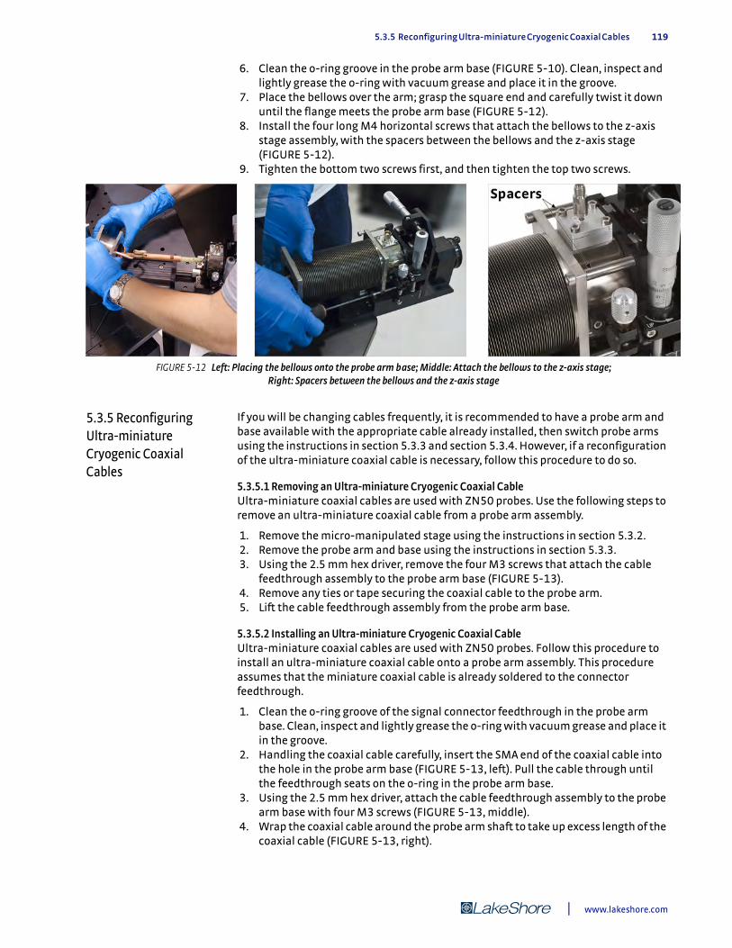
5.3.5 Reconfiguring Ultra-miniature Cryogenic Coaxial Cables 119
6. Clean the o-ring groove in the probe arm base (FIGURE 5-10). Clean, inspect and lightly grease the o-ring with vacuum grease and place it in the groove.
7. Place the bellows over the arm; grasp the square end and carefully twist it down until the flange meets the probe arm base (FIGURE 5-12).
8. Install the four long M4 horizontal screws that attach the bellows to the z-axis stage assembly, with the spacers between the bellows and the z-axis stage (FIGURE 5-12).
9. Tighten the bottom two screws first, and then tighten the top two screws.
5.3.5 Reconfiguring Ultra-miniature Cryogenic Coaxial Cables
If you will be changing cables frequently, it is recommended to have a probe arm and base available with the appropriate cable already installed, then switch probe arms using the instructions in section 5.3.3 and section 5.3.4. However, if a reconfiguration of the ultra-miniature coaxial cable is necessary, follow this procedure to do so.
5.3.5.1 Removing an Ultra-miniature Cryogenic Coaxial CableUltra-miniature coaxial cables are used with ZN50 probes. Use the following steps to remove an ultra-miniature coaxial cable from a probe arm assembly.
1. Remove the micro-manipulated stage using the instructions in section 5.3.2. 2. Remove the probe arm and base using the instructions in section 5.3.3. 3. Using the 2.5 mm hex driver, remove the four M3 screws that attach the cable
feedthrough assembly to the probe arm base (FIGURE 5-13). 4. Remove any ties or tape securing the coaxial cable to the probe arm. 5. Lift the cable feedthrough assembly from the probe arm base.
5.3.5.2 Installing an Ultra-miniature Cryogenic Coaxial CableUltra-miniature coaxial cables are used with ZN50 probes. Follow this procedure to install an ultra-miniature coaxial cable onto a probe arm assembly. This procedure assumes that the miniature coaxial cable is already soldered to the connector feedthrough.
1. Clean the o-ring groove of the signal connector feedthrough in the probe arm base. Clean, inspect and lightly grease the o-ring with vacuum grease and place it in the groove.
2. Handling the coaxial cable carefully, insert the SMA end of the coaxial cable into the hole in the probe arm base (FIGURE 5-13, left). Pull the cable through until the feedthrough seats on the o-ring in the probe arm base.
3. Using the 2.5 mm hex driver, attach the cable feedthrough assembly to the probe arm base with four M3 screws (FIGURE 5-13, middle).
4. Wrap the coaxial cable around the probe arm shaft to take up excess length of the coaxial cable (FIGURE 5-13, right).
FIGURE 5-12 Left: Placing the bellows onto the probe arm base; Middle: Attach the bellows to the z-axis stage; Right: Spacers between the bellows and the z-axis stage
| www.lakeshore.com
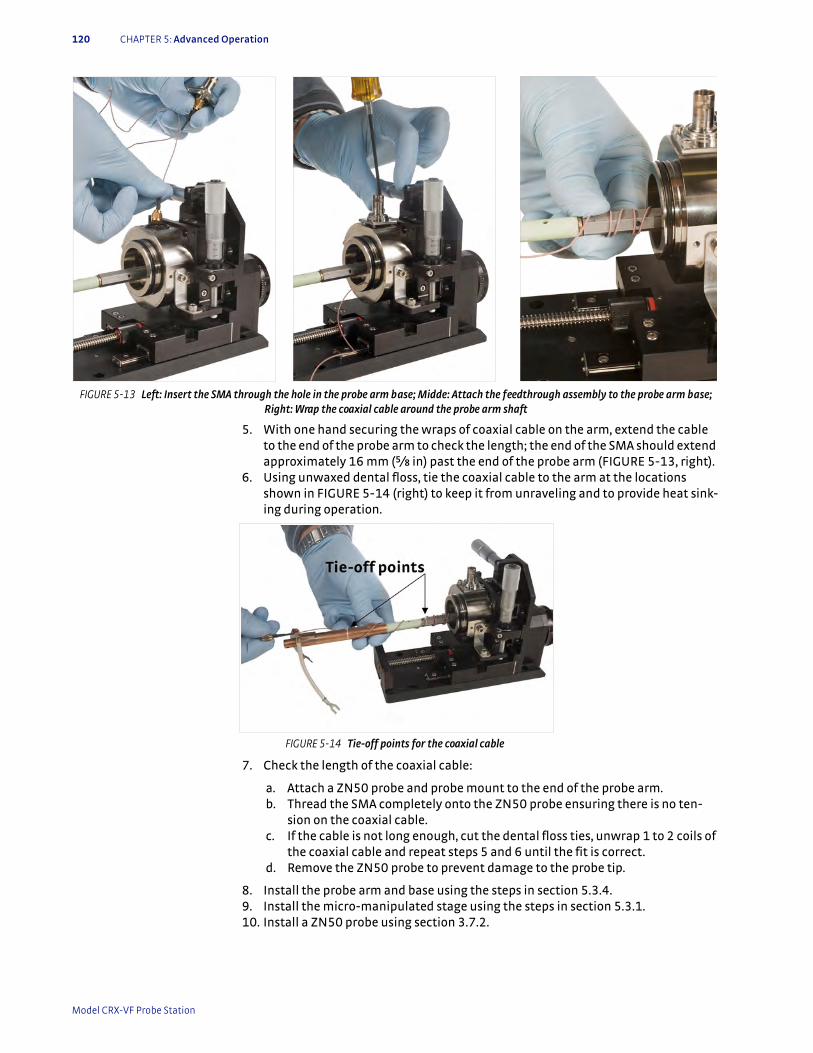
120 CHAPTER 5: Advanced Operation
5. With one hand securing the wraps of coaxial cable on the arm, extend the cable to the end of the probe arm to check the length; the end of the SMA should extend approximately 16 mm (5/i in) past the end of the probe arm (FIGURE 5-13, right).
6. Using unwaxed dental floss, tie the coaxial cable to the arm at the locations shown in FIGURE 5-14 (right) to keep it from unraveling and to provide heat sink-ing during operation.
7. Check the length of the coaxial cable:
a. Attach a ZN50 probe and probe mount to the end of the probe arm. b. Thread the SMA completely onto the ZN50 probe ensuring there is no ten-
sion on the coaxial cable. c. If the cable is not long enough, cut the dental floss ties, unwrap 1 to 2 coils of
the coaxial cable and repeat steps 5 and 6 until the fit is correct. d. Remove the ZN50 probe to prevent damage to the probe tip.
8. Install the probe arm and base using the steps in section 5.3.4. 9. Install the micro-manipulated stage using the steps in section 5.3.1. 10. Install a ZN50 probe using section 3.7.2.
FIGURE 5-13 Left: Insert the SMA through the hole in the probe arm base; Midde: Attach the feedthrough assembly to the probe arm base; Right: Wrap the coaxial cable around the probe arm shaft
FIGURE 5-14 Tie-off points for the coaxial cable
Model CRX-VF Probe Station
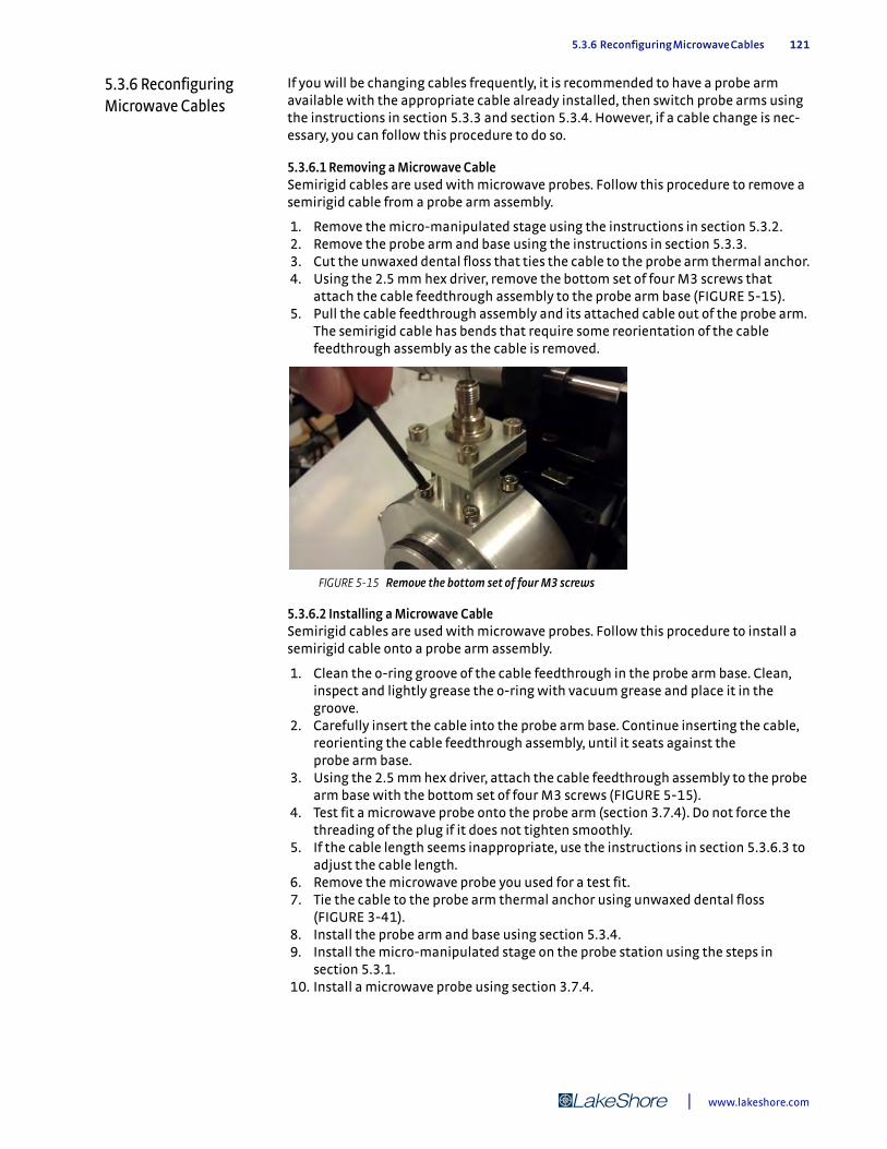
5.3.6 Reconfiguring Microwave Cables 121
5.3.6 Reconfiguring Microwave Cables
If you will be changing cables frequently, it is recommended to have a probe arm available with the appropriate cable already installed, then switch probe arms using the instructions in section 5.3.3 and section 5.3.4. However, if a cable change is nec-essary, you can follow this procedure to do so.
5.3.6.1 Removing a Microwave CableSemirigid cables are used with microwave probes. Follow this procedure to remove a semirigid cable from a probe arm assembly.
1. Remove the micro-manipulated stage using the instructions in section 5.3.2. 2. Remove the probe arm and base using the instructions in section 5.3.3. 3. Cut the unwaxed dental floss that ties the cable to the probe arm thermal anchor. 4. Using the 2.5 mm hex driver, remove the bottom set of four M3 screws that
attach the cable feedthrough assembly to the probe arm base (FIGURE 5-15). 5. Pull the cable feedthrough assembly and its attached cable out of the probe arm.
The semirigid cable has bends that require some reorientation of the cable feedthrough assembly as the cable is removed.
5.3.6.2 Installing a Microwave CableSemirigid cables are used with microwave probes. Follow this procedure to install a semirigid cable onto a probe arm assembly.
1. Clean the o-ring groove of the cable feedthrough in the probe arm base. Clean, inspect and lightly grease the o-ring with vacuum grease and place it in the groove.
2. Carefully insert the cable into the probe arm base. Continue inserting the cable, reorienting the cable feedthrough assembly, until it seats against the probe arm base.
3. Using the 2.5 mm hex driver, attach the cable feedthrough assembly to the probe arm base with the bottom set of four M3 screws (FIGURE 5-15).
4. Test fit a microwave probe onto the probe arm (section 3.7.4). Do not force the threading of the plug if it does not tighten smoothly.
5. If the cable length seems inappropriate, use the instructions in section 5.3.6.3 to adjust the cable length.
6. Remove the microwave probe you used for a test fit. 7. Tie the cable to the probe arm thermal anchor using unwaxed dental floss
(FIGURE 3-41). 8. Install the probe arm and base using section 5.3.4. 9. Install the micro-manipulated stage on the probe station using the steps in
section 5.3.1. 10. Install a microwave probe using section 3.7.4.
FIGURE 5-15 Remove the bottom set of four M3 screws
| www.lakeshore.com

122 CHAPTER 5: Advanced Operation
5.3.6.3 Adjusting the Fit of Microwave CablesAn appropriately fitted cable will tighten to the probe connector while the probe arm touches flush or is less than 2 mm from the probe mount. However, there are two sit-uations for which you may need to make adjustments of your semirigid high fre-quency cables. First, if the connector plug does not smoothly tighten to the probe socket, you will need to make an adjustment. If there is too much tension or misalign-ment in mating the semirigid cable to the connector, the high frequency connectors may be damaged. Second, if you are able to tighten the connector plug to the probe socket, but there is more than a 2 mm gap between the probe arm and the probe body, then you will need to make an adjustment.
A few adjustments can be made to change the relative positions of the cables and the probes. These are listed in order of increasing difficulty. The more difficult methods allow for more adjustment range.
First Method: Rotate the Cable Feedthrough Assembly 1. Remove the micro-manipulated stage following the steps in section 5.3.2. 2. Optional: Remove the bellows following steps 1 to 2 in section 5.3.3. 3. Remove the top set of four M3 screws holding the cable feedthrough to the
feedthrough tower (FIGURE 5-16).
4. Gently pull up on the feedthrough, and using an 8 mm torque wrench, loosen the connection of the semirigid cable to the feedthrough so that the feedthrough may be rotated.
5. Rotate the feedthrough assembly into position and retighten the connection. The cable does not pass through the center of the feedthrough assembly (FIGURE 5-17). Rotating this assembly changes the position of the cable end that attaches to the probe.
FIGURE 5-16 Remove the top set of four M3 screws
FIGURE 5-17 Left: Rotate the feedthrough assembly into position and retighten the connection; Right: The off-centered position on the cable feedthrough assembly
Model CRX-VF Probe Station
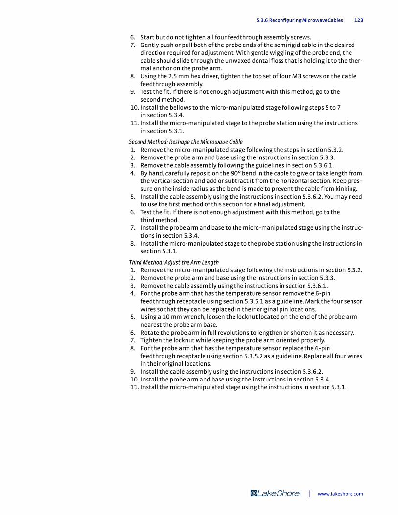
5.3.6 Reconfiguring Microwave Cables 123
6. Start but do not tighten all four feedthrough assembly screws. 7. Gently push or pull both of the probe ends of the semirigid cable in the desired
direction required for adjustment. With gentle wiggling of the probe end, the cable should slide through the unwaxed dental floss that is holding it to the ther-mal anchor on the probe arm.
8. Using the 2.5 mm hex driver, tighten the top set of four M3 screws on the cable feedthrough assembly.
9. Test the fit. If there is not enough adjustment with this method, go to the second method.
10. Install the bellows to the micro-manipulated stage following steps 5 to 7 in section 5.3.4.
11. Install the micro-manipulated stage to the probe station using the instructions in section 5.3.1.
Second Method: Reshape the Microwave Cable 1. Remove the micro-manipulated stage following the steps in section 5.3.2. 2. Remove the probe arm and base using the instructions in section 5.3.3. 3. Remove the cable assembly following the guidelines in section 5.3.6.1. 4. By hand, carefully reposition the 90° bend in the cable to give or take length from
the vertical section and add or subtract it from the horizontal section. Keep pres-sure on the inside radius as the bend is made to prevent the cable from kinking.
5. Install the cable assembly using the instructions in section 5.3.6.2. You may need to use the first method of this section for a final adjustment.
6. Test the fit. If there is not enough adjustment with this method, go to the third method.
7. Install the probe arm and base to the micro-manipulated stage using the instruc-tions in section 5.3.4.
8. Install the micro-manipulated stage to the probe station using the instructions in section 5.3.1.
Third Method: Adjust the Arm Length 1. Remove the micro-manipulated stage following the instructions in section 5.3.2. 2. Remove the probe arm and base using the instructions in section 5.3.3. 3. Remove the cable assembly using the instructions in section 5.3.6.1. 4. For the probe arm that has the temperature sensor, remove the 6-pin
feedthrough receptacle using section 5.3.5.1 as a guideline. Mark the four sensor wires so that they can be replaced in their original pin locations.
5. Using a 10 mm wrench, loosen the locknut located on the end of the probe arm nearest the probe arm base.
6. Rotate the probe arm in full revolutions to lengthen or shorten it as necessary. 7. Tighten the locknut while keeping the probe arm oriented properly. 8. For the probe arm that has the temperature sensor, replace the 6-pin
feedthrough receptacle using section 5.3.5.2 as a guideline. Replace all four wires in their original locations.
9. Install the cable assembly using the instructions in section 5.3.6.2. 10. Install the probe arm and base using the instructions in section 5.3.4. 11. Install the micro-manipulated stage using the instructions in section 5.3.1.
| www.lakeshore.com
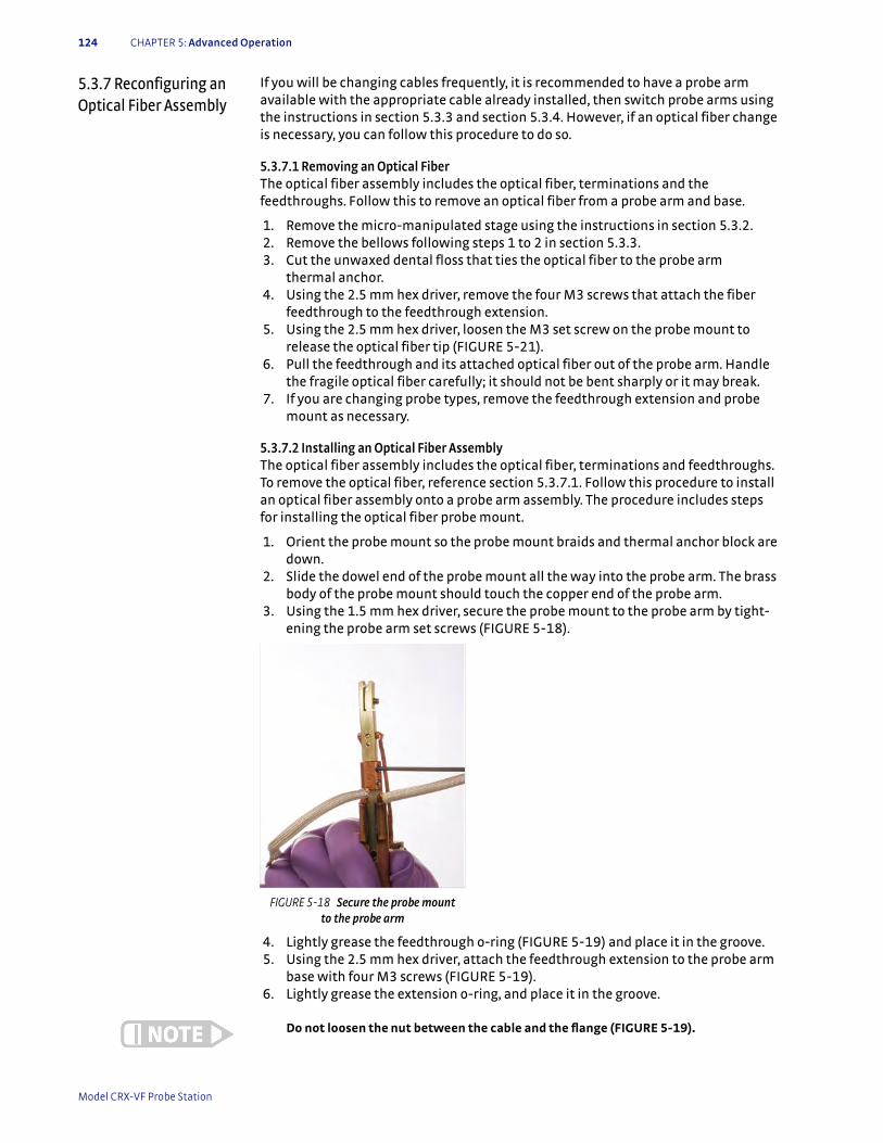
124 CHAPTER 5: Advanced Operation
5.3.7 Reconfiguring an Optical Fiber Assembly
If you will be changing cables frequently, it is recommended to have a probe arm available with the appropriate cable already installed, then switch probe arms using the instructions in section 5.3.3 and section 5.3.4. However, if an optical fiber change is necessary, you can follow this procedure to do so.
5.3.7.1 Removing an Optical FiberThe optical fiber assembly includes the optical fiber, terminations and the feedthroughs. Follow this to remove an optical fiber from a probe arm and base.
1. Remove the micro-manipulated stage using the instructions in section 5.3.2. 2. Remove the bellows following steps 1 to 2 in section 5.3.3. 3. Cut the unwaxed dental floss that ties the optical fiber to the probe arm
thermal anchor. 4. Using the 2.5 mm hex driver, remove the four M3 screws that attach the fiber
feedthrough to the feedthrough extension. 5. Using the 2.5 mm hex driver, loosen the M3 set screw on the probe mount to
release the optical fiber tip (FIGURE 5-21). 6. Pull the feedthrough and its attached optical fiber out of the probe arm. Handle
the fragile optical fiber carefully; it should not be bent sharply or it may break. 7. If you are changing probe types, remove the feedthrough extension and probe
mount as necessary.
5.3.7.2 Installing an Optical Fiber AssemblyThe optical fiber assembly includes the optical fiber, terminations and feedthroughs. To remove the optical fiber, reference section 5.3.7.1. Follow this procedure to install an optical fiber assembly onto a probe arm assembly. The procedure includes steps for installing the optical fiber probe mount.
1. Orient the probe mount so the probe mount braids and thermal anchor block are down.
2. Slide the dowel end of the probe mount all the way into the probe arm. The brass body of the probe mount should touch the copper end of the probe arm.
3. Using the 1.5 mm hex driver, secure the probe mount to the probe arm by tight-ening the probe arm set screws (FIGURE 5-18).
4. Lightly grease the feedthrough o-ring (FIGURE 5-19) and place it in the groove. 5. Using the 2.5 mm hex driver, attach the feedthrough extension to the probe arm
base with four M3 screws (FIGURE 5-19). 6. Lightly grease the extension o-ring, and place it in the groove.
Do not loosen the nut between the cable and the flange (FIGURE 5-19).
FIGURE 5-18 Secure the probe mount to the probe arm
Model CRX-VF Probe Station
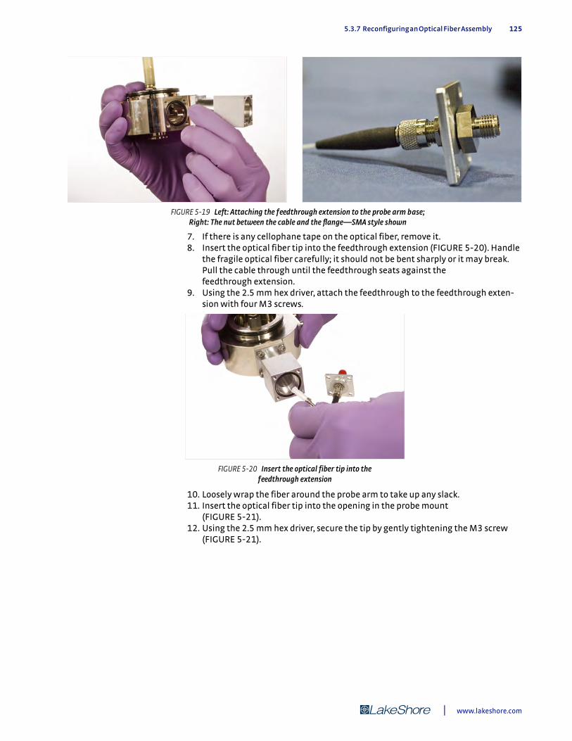
5.3.7 Reconfiguring an Optical Fiber Assembly 125
7. If there is any cellophane tape on the optical fiber, remove it. 8. Insert the optical fiber tip into the feedthrough extension (FIGURE 5-20). Handle
the fragile optical fiber carefully; it should not be bent sharply or it may break. Pull the cable through until the feedthrough seats against the feedthrough extension.
9. Using the 2.5 mm hex driver, attach the feedthrough to the feedthrough exten-sion with four M3 screws.
10. Loosely wrap the fiber around the probe arm to take up any slack. 11. Insert the optical fiber tip into the opening in the probe mount
(FIGURE 5-21). 12. Using the 2.5 mm hex driver, secure the tip by gently tightening the M3 screw
(FIGURE 5-21).
FIGURE 5-19 Left: Attaching the feedthrough extension to the probe arm base; Right: The nut between the cable and the flange—SMA style shown
FIGURE 5-20 Insert the optical fiber tip into the feedthrough extension
| www.lakeshore.com
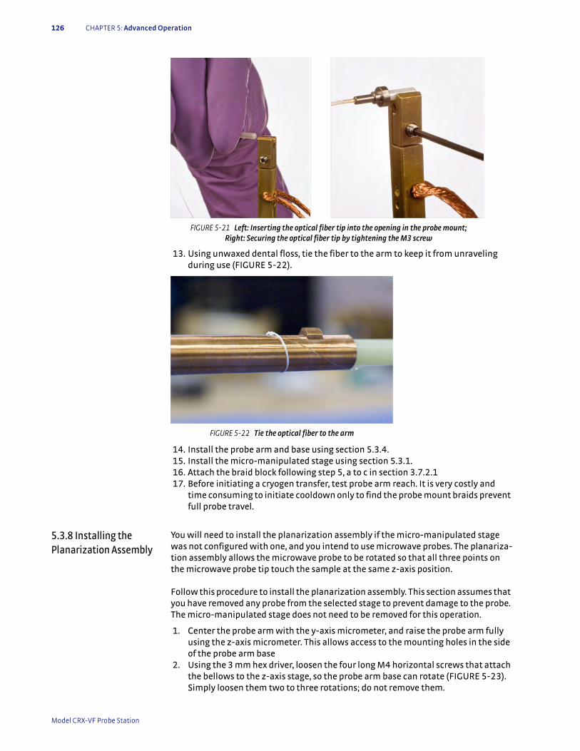
126 CHAPTER 5: Advanced Operation
13. Using unwaxed dental floss, tie the fiber to the arm to keep it from unraveling during use (FIGURE 5-22).
14. Install the probe arm and base using section 5.3.4. 15. Install the micro-manipulated stage using section 5.3.1. 16. Attach the braid block following step 5, a to c in section 3.7.2.1 17. Before initiating a cryogen transfer, test probe arm reach. It is very costly and
time consuming to initiate cooldown only to find the probe mount braids prevent full probe travel.
5.3.8 Installing the Planarization Assembly
You will need to install the planarization assembly if the micro-manipulated stage was not configured with one, and you intend to use microwave probes. The planariza-tion assembly allows the microwave probe to be rotated so that all three points on the microwave probe tip touch the sample at the same z-axis position.
Follow this procedure to install the planarization assembly. This section assumes that you have removed any probe from the selected stage to prevent damage to the probe. The micro-manipulated stage does not need to be removed for this operation.
1. Center the probe arm with the y-axis micrometer, and raise the probe arm fully using the z-axis micrometer. This allows access to the mounting holes in the side of the probe arm base
2. Using the 3 mm hex driver, loosen the four long M4 horizontal screws that attach the bellows to the z-axis stage, so the probe arm base can rotate (FIGURE 5-23). Simply loosen them two to three rotations; do not remove them.
FIGURE 5-21 Left: Inserting the optical fiber tip into the opening in the probe mount; Right: Securing the optical fiber tip by tightening the M3 screw
FIGURE 5-22 Tie the optical fiber to the arm
Model CRX-VF Probe Station
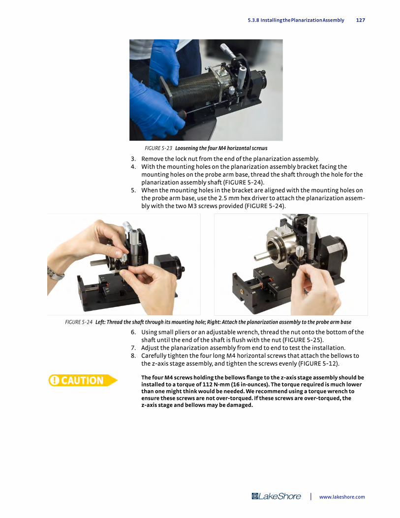
5.3.8 Installing the Planarization Assembly 127
3. Remove the lock nut from the end of the planarization assembly. 4. With the mounting holes on the planarization assembly bracket facing the
mounting holes on the probe arm base, thread the shaft through the hole for the planarization assembly shaft (FIGURE 5-24).
5. When the mounting holes in the bracket are aligned with the mounting holes on the probe arm base, use the 2.5 mm hex driver to attach the planarization assem-bly with the two M3 screws provided (FIGURE 5-24).
6. Using small pliers or an adjustable wrench, thread the nut onto the bottom of the shaft until the end of the shaft is flush with the nut (FIGURE 5-25).
7. Adjust the planarization assembly from end to end to test the installation. 8. Carefully tighten the four long M4 horizontal screws that attach the bellows to
the z-axis stage assembly, and tighten the screws evenly (FIGURE 5-12).
The four M4 screws holding the bellows flange to the z-axis stage assembly should be installed to a torque of 112 N·mm (16 in·ounces). The torque required is much lower than one might think would be needed. We recommend using a torque wrench to ensure these screws are not over-torqued. If these screws are over-torqued, the z-axis stage and bellows may be damaged.
FIGURE 5-23 Loosening the four M4 horizontal screws
FIGURE 5-24 Left: Thread the shaft through its mounting hole; Right: Attach the planarization assembly to the probe arm base
| www.lakeshore.com
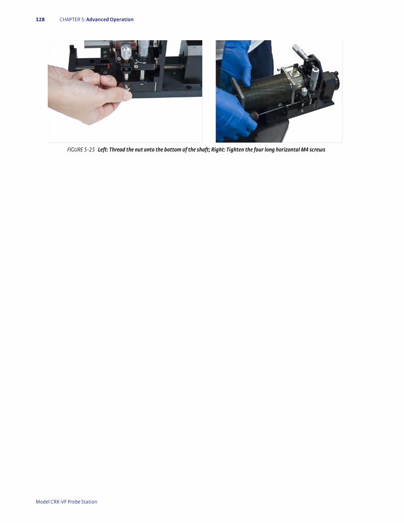
128 CHAPTER 5: Advanced Operation
FIGURE 5-25 Left: Thread the nut onto the bottom of the shaft; Right: Tighten the four long horizontal M4 screws
Model CRX-VF Probe Station
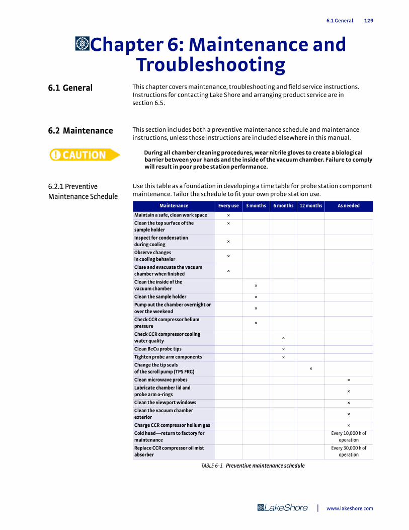
6.1 General 129
Chapter 6: Maintenance and Troubleshooting
6.1 General This chapter covers maintenance, troubleshooting and field service instructions. Instructions for contacting Lake Shore and arranging product service are in section 6.5.
6.2 Maintenance This section includes both a preventive maintenance schedule and maintenance instructions, unless those instructions are included elsewhere in this manual.
During all chamber cleaning procedures, wear nitrile gloves to create a biological barrier between your hands and the inside of the vacuum chamber. Failure to comply will result in poor probe station performance.
6.2.1 Preventive Maintenance Schedule
Use this table as a foundation in developing a time table for probe station component maintenance. Tailor the schedule to fit your own probe station use.
Maintenance Every use 3 months 6 months 12 months As needed
Maintain a safe, clean work space ×
Clean the top surface of the sample holder
×
Inspect for condensation during cooling
×
Observe changes in cooling behavior
×
Close and evacuate the vacuum chamber when finished
×
Clean the inside of the vacuum chamber
×
Clean the sample holder ×
Pump out the chamber overnight or over the weekend
×
Check CCR compressor helium pressure
×
Check CCR compressor cooling water quality
×
Clean BeCu probe tips ×
Tighten probe arm components ×
Change the tip seals of the scroll pump (TPS FRG)
×
Clean microwave probes ×
Lubricate chamber lid and probe arm o-rings
×
Clean the viewport windows ×
Clean the vacuum chamber exterior
×
Charge CCR compressor helium gas ×
Cold head—return to factory for maintenance
Every 10,000 h of operation
Replace CCR compressor oil mist absorber
Every 30,000 h of operation
TABLE 6-1 Preventive maintenance schedule
| www.lakeshore.com
130 cHAPTER 6: Maintenance and Troubleshooting
6.2.2 Cleaning the Vacuum Chamber Exterior
The exterior of the probe station chamber should be kept generally clean and clear of dust and other possible contaminants. Surfaces may be wiped down using damp, lint-free cloths like Kimwipes®. Isopropyl alcohol on a lint-free cloth is recommended to loosen adhesives and other residue. Dust on the exterior may also be removed with a commercially available compressed air product such as Dust Off®.
6.2.3 Cleaning the Vacuum Chamber Interior
Failure to keep the chamber clean and store it under vacuum will result in poor probe station performance due to contaminants and moisture in the chamber. A dirty chamber requires longer pump down times, more helium to cool, and results in higher base temperatures. If the CRX-VF chamber is not properly maintained, it will be increasingly difficult to operate the sample stage at the specified base temperature.
1. Prior to cleaning, remove the following:
D Vacuum chamber lidD Radiation shield lid D Main chamber o-ringD Sample holderD Probes
2. Wipe down the following surfaces with a lint-free wipe like Kimwipes® and iso-propyl alcohol. Do not clean the viewports during this step.
D Top edge of the radiation shield (mating surface)D Mating surfaces of the radiation shield lid D Any surface that shows fingerprints D Any surface likely touched during sample exchange D Sealing surface of the vacuum chamber lidD Main chamber o-ring D Main chamber o-ring groove
The radiation curtains are very fragile; do not soak them or rub them as they can come off or break.
3. Clean and lubricate the chamber components:
D Clean the viewport windows (section 6.2.4)D Lubricate the main chamber o-rings with a thin layer of high quality vacuum
grease (section 6.2.5)D Clean the sample holder (section 6.2.6)
4. Reassemble the probe station:
D Sample holderD ProbesD Main chamber o-ringD Radiation shield lidD Vacuum chamber lid
5. Evacuate the chamber for 30 min prior to loading a sample.
To minimize the risk of contamination, the radiation shield lid and vacuum chamber lid should remain in place except when working in the chamber. Lake Shore also recommends that you store the chamber under vacuum to reduce oxidation.
Model CRX-VF Probe Station
6.2.4 Viewport Window Maintenance 131
6.2.4 Viewport Window Maintenance
Viewport windows require extra consideration. It is important to protect the optics as they are your only way to view and photograph the activity on the sample holder.
6.2.4.1 Cleaning the Viewport WindowsThe viewport windows on the radiation shield lid and vacuum chamber lid will need cleaning, as they collect debris and smudges during normal operation. Use cleaners recommended for glass optics. A suggested cleaner is Eclipse® High Purity Cleaning Fluid, available through Edmund Optics.
Never use household cleaners on the optics windows; some optics may be damaged by the chemicals in these cleaners.
6.2.4.2 De-fogging the Viewport WindowsSome condensation on the outside of the vacuum chamber lid viewport windows is normal; however, if there is condensation on the inside of the vacuum chamber lid viewport windows or anywhere on the radiation shield lid, this is a sign of poor vacuum. Refer to section 6.3.1. When the outside of the vacuum chamber viewport window develops condensation during low temperature operation, it is an indication that it needs to be treated with anti-fog solution. A suggested anti-fog solution is Parker’s™ Perfect anti-fogging solution, available through Edmunds Optics.
Follow this procedure to de-fog the outside surface of the vacuum chamber viewport windows.
1. Apply anti-fog solution to a small, folded, optical cloth. 2. Wipe onto the surface of the viewport using a circular and overlapping motion. 3. Allow the solution to dry until a slight haze appears. 4. Apply a second coat using a new cloth and fresh solution to ensure complete and
uniform coverage. 5. Remove the final haze with a clean, dry cotton cloth.
6.2.5 O-Ring Maintenance
O-rings are generally reliable and require very little maintenance. Periodic cleaning and re-greasing is all that is necessary under most circumstances. This is especially true of the vacuum chamber lid o-ring that is located where it can be contaminated with debris. Other o-rings will require routine maintenance only if their seal is broken regularly to reconfigure the probe station.
6.2.5.1 Re-greasing O-Rings Follow this procedure to re-grease o-rings. Wear nitrile gloves during this procedure.
1. Remove the o-ring using the plastic o-ring removal tool provided in the tool kit. 2. Clean off any old grease with a lint-free wipe and isopropyl alcohol. 3. Clean the o-ring groove and mating surface with a lint-free wipe and
isopropyl alcohol. 4. Inspect for small cuts or nicks; if you find any, replace the o-ring immediately. 5. Inspect for excessive flattening; replace immediately if found. 6. Place a small amount of high quality vacuum grease, such as Apiezon® N grease
on one (gloved) finger. 7. Run the o-ring through your fingers until the entire surface is lightly coated. 8. Remove any excess grease. 9. Replace the o-ring in the o-ring groove; do not allow the o-ring to twist
in the groove.
| www.lakeshore.com
132 cHAPTER 6: Maintenance and Troubleshooting
6.2.5.2 Accessing Other O-RingsThe o-ring on the vacuum chamber lid is easy to locate. This section describes the location of the other o-rings in the system if you need to access them for maintenance or service.
Viewport window: the viewport window is sealed to the vacuum chamber lid with an o-ring.
Bellows: there is an o-ring sealing each end of each bellows. They can be accessed by following the instructions in section 5.3.2 and section 5.3.3.
Signal connector feedthrough: there is an o-ring between each signal connector feedthrough and its probe arm base. It can be accessed using the instructions in section 5.3.5 as a guide.
Probe arm temperature feedthrough: there is an o-ring between the probe arm base and the 6-pin feedthrough used for the probe arm temperature sensor. This port will be blanked off if there is not a sensor on the arm. It can be accessed using instructions in section 5.3.6.3 (third method) as a guide.
Vacuum chamber ports: the NW 40 and NW 25 gauge port, the load lock port and the high vacuum port on the CRX-VF chamber has an o-ring sealing the blank-off flange to the chamber.
Vacuum chamber base: there is an o-ring sealing the vacuum chamber to its base. Accessing this o-ring requires dropping the sample cooling assembly out of the vacuum chamber. This operation is not recommended for routine maintenance. Please contact Lake Shore service before attempting to drop the sample cooling assembly if you suspect a leak.
Vacuum chamber base feedthroughs: there are a number of electrical and mechanical feedthroughs located on the base of the vacuum chamber and each contains an o-ring. The seals on these feedthroughs are not normally broken during reconfiguration of the probe station. Please contact Lake Shore service before attempting to service these o-rings if you suspect a leak.
6.2.6 Cleaning the Sample Holder
We recommend cleaning sample holders between uses to ensure samples make good thermal contact. Considering the many possible methods used to mount samples onto the sample holders, a variety of methods are necessary to clean them.
Chemical solvents are recommended over mechanical removal methods. The gold plating on the top surface of many sample holders is delicate and will not hold up to abrasives, scrubbing or scratching. Follow the manufacturer’s recommendations for removing sample mounting materials such as photoresist.
Be sure that all chemicals are compatible with the materials in the sample holder. Most solvents and removers are compatible with the copper and gold grounded sample holders. Coaxial and triaxial sample holders also contain Kapton® and solder. Isolated sample holders use sapphire.
Only work with volatile or toxic chemicals (xylene, acetone, etc.) in a well ventilated area or under a fume hood.
To remove the sample mounting material:
D Apiezon® N grease can be removed using xylene with an isopropyl alcohol rinse
Model CRX-VF Probe Station
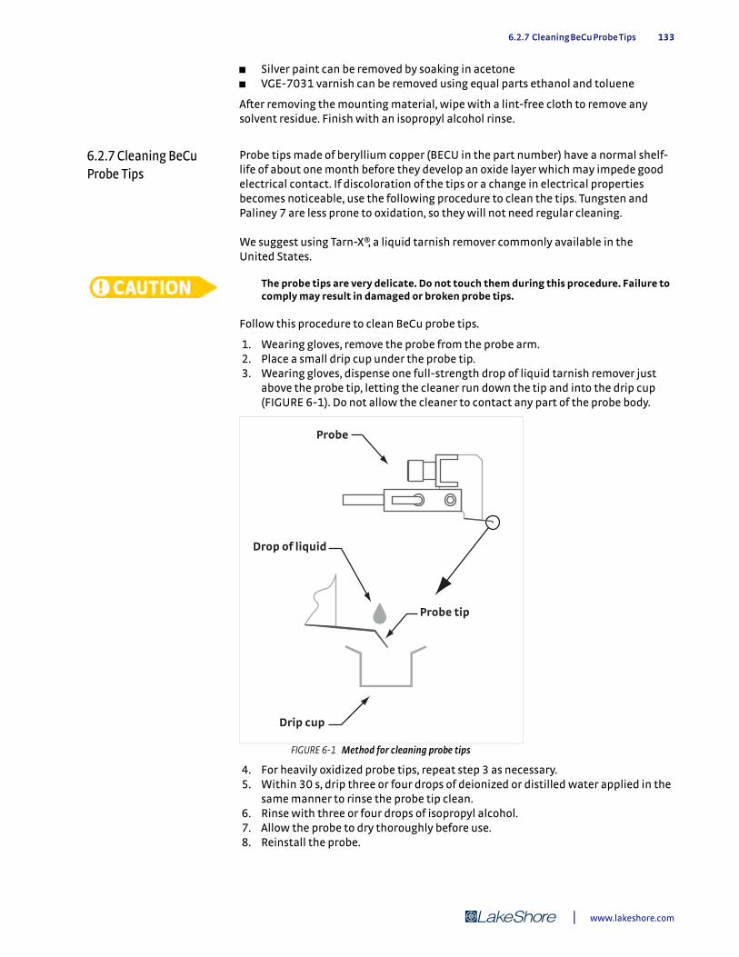
6.2.7 Cleaning BeCu Probe Tips 133
D Silver paint can be removed by soaking in acetoneD VGE-7031 varnish can be removed using equal parts ethanol and toluene
After removing the mounting material, wipe with a lint-free cloth to remove any solvent residue. Finish with an isopropyl alcohol rinse.
6.2.7 Cleaning BeCu Probe Tips
Probe tips made of beryllium copper (BECU in the part number) have a normal shelf-life of about one month before they develop an oxide layer which may impede good electrical contact. If discoloration of the tips or a change in electrical properties becomes noticeable, use the following procedure to clean the tips. Tungsten and Paliney 7 are less prone to oxidation, so they will not need regular cleaning.
We suggest using Tarn-X®, a liquid tarnish remover commonly available in the United States.
The probe tips are very delicate. Do not touch them during this procedure. Failure to comply may result in damaged or broken probe tips.
Follow this procedure to clean BeCu probe tips.
1. Wearing gloves, remove the probe from the probe arm. 2. Place a small drip cup under the probe tip. 3. Wearing gloves, dispense one full-strength drop of liquid tarnish remover just
above the probe tip, letting the cleaner run down the tip and into the drip cup (FIGURE 6-1). Do not allow the cleaner to contact any part of the probe body.
4. For heavily oxidized probe tips, repeat step 3 as necessary. 5. Within 30 s, drip three or four drops of deionized or distilled water applied in the
same manner to rinse the probe tip clean. 6. Rinse with three or four drops of isopropyl alcohol. 7. Allow the probe to dry thoroughly before use. 8. Reinstall the probe.
FIGURE 6-1 Method for cleaning probe tips
Drop of liquid
Probe
Probe tip
Drip cup
| www.lakeshore.com
134 cHAPTER 6: Maintenance and Troubleshooting
6.2.8 Cleaning Microwave Probe Points
The points on microwave tips are extremely delicate and require great care in both handling and cleaning.
6.2.8.1 General Cleaning 1. Immerse the probe tip only in a bath of isopropyl alcohol or acetone in an ultra-
sonic cleaner. 2. Cycle the ultrasonic cleaner on and off in very short bursts several times. If you do
not have an ultrasonic cleaner, simply dip the tip into a bath of acetone. 3. Finish with a rinse in isopropyl alcohol. 4. Allow the probe to air dry thoroughly for several hours (preferably overnight)
before use so that no liquid remains within the air gap between the points, or a short will result.
Do not use high velocity compressed air directly on the probe tip; the nozzle must be kept 10 in to 12 in away if used. Do not use a brush or cotton swab to wipe the probe tip.
6.2.8.2 Removing Oxidation 1. Tape a piece of clean card stock or heavy paper onto the sample holder. 2. Touch the probe down on the paper slightly so that the ground points begin to
flex and slowly drag the probe backward across the paper a distance of 1 mm.
Do not drive the tip forward into the paper, or you will damage the points.
3. In severe cases, touch the probe tips down onto a piece of smooth ceramic and drag the probe backwards 1 mm.
This process quickly removes the oxide, but also removes some of the tip material and can result in reduced probe life.
4. After removing oxidation, clean the probe as described in section 6.2.8.1.
6.2.9 Probe Arm Maintenance
The probe arms and stages require very little maintenance; however, some of the fasteners do need to be re-tightened periodically due to thermal cycling or repeated movement. Fasteners associated with thermal interfaces, electrical conduction and mechanical stability should be checked regularly. The instructions for re-tightening these components are the same as those for installation or operation so they are not repeated here.
Tightening the braid block: please reference step 5 in section 3.7.2.1 if you need to tighten a braid block.
Tightening the probe mount: please reference step 4 in section 3.7.2.1.
Tightening the arm shield braids: please reference FIGURE 5-8 in section 5.3.1.
Tightening the probe arm into the probe arm base: follow this procedure to tighten the probe arm.
1. Remove the micro-manipulated stage using the instructions in section 5.3.2. 2. Remove the probe arm and base using the instructions in section 5.3.3. 3. Using the 10 mm wrench, tighten the locknut that secures the threaded brass
anchor of the probe arm to the hex standoff of the probe arm base while keeping the probe arm oriented properly.
4. Install the probe arm and base using the instructions in section 5.3.4. 5. Install the micro-manipulated stage using the instructions in section 5.3.1.
Model CRX-VF Probe Station
6.2.10 CCR Maintenance 135
6.2.10 CCR Maintenance
This section provides instructions on maintaining the CCR.
6.2.10.1 Charging the CCR Compressor Helium GasCharge the CCR compressor helium gas if the pressure indication on the supply pressure is lower than the value specified in section 3.2.6. Note that the supply pressure is dependent on both the cold head temperature and the ambient temperature. Wait until the cold head is at ambient room temperature to make an accurate reading of the supply pressure. If the ambient temperature of the room is unusually lower or higher than normal for your facility, then the supply pressure may also read low or high, respectively. It is best to wait until the ambient room temperature is representative of normal operating conditions prior to charging the helium gas. Refer to the SRDK Series Cryocooler Operation Manual for specific instructions on charging the helium gas.
6.2.10.2 CCR Cold Head 10,000 Hour MaintenanceThe moving parts within the CCR cold head require service after approximately 10,000 h of operation. If your CRX-VF probe station is approaching the 10,000 h operation point, you will need to return the CCR cold head to Lake Shore for service; contact Lake Shore or your local representative to schedule this service.
6.2.10.3 CCR Compressor Oil Mist Adsorber 30,000 Hour MaintenanceThe oil mist adsorber inside the CCR compressor should be changed after approximately 30,000 h of operation to ensure the purity of the helium gas in the CCR cold head. You may contact SHI directly to obtain the replacement adsorber, or contact Lake Shore or your local representative to obtain a replacement adsorber. Refer to the F-70 Compressor Unit Technical Instruction for the manufacturer’s part number and specific instructions on changing the adsorber.
6.2.11 Vacuum Pump Maintenance
It is difficult to give specific instructions for all possible combinations of pumps that may be used with the CRX-VF. Refer to the information included with your selected vacuum pump for specific maintenance instructions, and add them to the preventive maintenance schedule in section 6.2.1 of this manual. Some general guidelines on vacuum pump maintenance follow.
6.2.11.1 Turbo PumpsTurbo pumps are generally considered maintenance-free, and contain no user-serviceable parts or maintenance items. Operate them according to manufacturer’s instructions for the longest possible service life.
6.2.11.2 Scroll Pumps Scroll pumps are frequently used because the fore pump for the turbo pump has replaceable seals called tips that wear with use. As the tips wear, pump performance degrades, but this seldom causes pump failure. The tips should be replaced when the pump no longer performs adequately. Some manufacturers recommend replacing the tips every year (depending on use) to keep the pump operating to specification. However, a scroll pump can still be adequate for use as a fore pump even when it is performing well below its specification.
6.2.11.3 Rotary-Vane PumpsRotary-vane pumps are often used as the fore pump for turbo pumps. These pumps contain oil, and therefore require routine maintenance.
The oil level in a rotary-vane pump should be checked at least every three months. Insufficient oil will cause catastrophic failure of the pump. If the oil level is low, add only the type of oil recommended by the pump manufacturer. Do not overfill the oil reservoir. Overfilling may cause oil to exhaust from the pump or shorten the service life of the pump.
| www.lakeshore.com
136 cHAPTER 6: Maintenance and Troubleshooting
The oil in a rotary-vane pump should be changed regularly. The time between changes varies based on hours of use and the type of gases being pumped. The oil itself can be an indicator of when it needs to be changed. The oil turns darker with use and should be changed when it becomes noticeably darker than new oil. Use an annual preventive maintenance to change the oil on oil-filled pumps..
6.2.11.4 Oil Mist Eliminators The exhaust of a rotary-vane pump is often fitted with an oil mist eliminator (filter). There are a variety of oil mist eliminators that may or may not include an inspection view port or replaceable filter element. If the eliminator is not serviced or replaced regularly, oil will exhaust from the pump. Consider scheduling service or replacement of the oil mist eliminator when the pump oil is changed.
6.2.11.5 Diaphragm Pumps On smaller probe stations, diaphragm pumps can be used as fore pumps for the turbo pump; however, even on smaller probe stations, the seals in the pump wear down and should be replaced periodically. Always follow the manufacturer’s recommendations to reduce potential down time.
6.2.12 Removing Condensation from Inside the Vacuum Chamber
Opening the vacuum chamber to atmosphere when the sample cooling assembly is at cryogenic temperatures allows water vapor to condense on the probe station and freeze into ice. It is possible for the probe station or turbo vacuum pump to suffer irreparable damage when this occurs. It can take as long as a week to return the probe station to proper working order. The time is required because water molecules are easily attracted to the surfaces inside the probe station, such as the convolutions in the bellows, and it is difficult for the vacuum pump to remove them.
To dry out the vacuum chamber and check for damage, follow this procedure:
1. If the sample cooling assembly is still cold, close the purge valve and vacuum iso-lation valve to prevent more moisture from entering the system.
2. Turn off and properly vent the turbo pump. The turbo pump should not be used in this process until all visible water has evaporated from the chamber.
3. Allow all stages to warm to room temperature (300 K). The temperature control-lers can be used for warm up, but they should be monitored closely in case any of the sensors were damaged.
Never heat any part of the probe station sample cooling assembly above room temperature unless the vacuum chamber is under vacuum.
4. Remove the chamber and radiation shield lids and sample holder. 5. Wait 24 h to 48 h for the system to dry until there is no visual condensation on
the inside or outside of the vacuum chamber. A small fan or heat lamp may speed this step.
6. Reinstall the sample holder, radiation shield lids and vacuum chamber lid. 7. Perform the heated cycle purge of the the vacuum chamber as outlined in
section 5.2.1.1. The initial pump down may take longer than normal due to water molecules still trapped in the vacuum chamber. An initial overnight (12 to 24 hr) pump down is recommended.
When warming the stages, be sure to monitor the stage temperatures closely until they stabilize in case any of the sensors were damaged.
8. If the station can attain <10-3 Torr, then go on to step 9; if not, contact the Lake Shore service department because the system may have a vacuum leak or other damage.
9. Use the procedures in section 3.8 to ensure basic functionality of the probe sta-tion and vacuum pump.
Model CRX-VF Probe Station

6.3 Troubleshooting Procedures 137
6.3 Troubleshooting Procedures
The following procedures should only be performed by skilled operators who are familiar with the required process and equipment. Damage to the probe station can result if these procedures are not done properly. If you require assistance, contact Lake Shore service or your local representative before beginning these procedures. Contact information is in section 6.5.
6.3.1 Vacuum Troubleshooting
The CRX-VF should be able to achieve a vacuum of <10-3 Torr at room temperature with an appropriate vacuum system and the gauge located on the chamber. If your vacuum does not perform similar to the curve illustrated in FIGURE 6-2, the following sections describe some common problems and simple diagnostic procedures to remedy this. If the problem is caused by a very small leak it may be necessary to use a leak detector to troubleshoot it properly. Leak detector operation is not covered in this manual. Consult your leak detector user’s manual.
Suspect poor vacuum if you observe any of the following symptoms:
D Sample cooling assembly will not cool to base temperatureD Cooling time increasesD Condensation appears on sample surfaceD Condensation appears on any internal viewport surfaceD Excessive condensation appears on exterior of chamber viewportD Magnet quenches even if magnet temperature is within range of operation
FIGURE 6-2 Typical CRX-VF pump down curve
| www.lakeshore.com
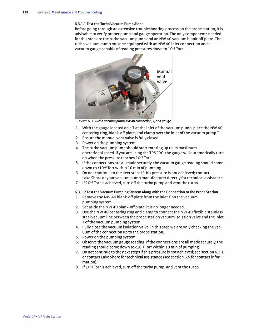
138 cHAPTER 6: Maintenance and Troubleshooting
6.3.1.1 Test the Turbo Vacuum Pump AloneBefore going through an extensive troubleshooting process on the probe station, it is advisable to verify proper pump and gauge operation. The only components needed for this step are the turbo vacuum pump and an NW 40 vacuum blank-off plate. The turbo vacuum pump must be equipped with an NW 40 inlet connection and a vacuum gauge capable of reading pressures down to 10-8 Torr.
1. With the gauge located on a T at the inlet of the vacuum pump, place the NW 40 centering ring, blank-off plate, and clamp over the inlet of the vacuum pump T.
2. Ensure the manual vent valve is fully closed. 3. Power on the pumping system. 4. The turbo vacuum pump should start rotating up to its maximum
operational speed. If you are using the TPS FRG, the gauge will automatically turn on when the pressure reaches 10-3 Torr.
5. If the connections are all made securely, the vacuum gauge reading should come down to <10-6 Torr within 10 min of pumping.
6. Do not continue to the next steps if this pressure is not achieved; contact Lake Shore or your vacuum pump manufacturer directly for technical assistance.
7. If 10-6 Torr is achieved, turn off the turbo pump and vent the turbo.
6.3.1.2 Test the Vacuum Pumping System Along with the Connection to the Probe Station 1. Remove the NW 40 blank-off plate from the inlet T on the vacuum
pumping system. 2. Set aside the NW 40 blank-off plate; it is no longer needed. 3. Use the NW 40 centering ring and clamp to connect the NW 40 flexible stainless
steel vacuum line between the probe station vacuum isolation valve and the inlet T of the vacuum pumping system.
4. Fully close the vacuum isolation valve; in this step we are only checking the vac-uum of the connection up to the probe station.
5. Power on the pumping system. 6. Observe the vacuum gauge reading. If the connections are all made securely, the
reading should come down to <10-5 Torr within 10 min of pumping. 7. Do not continue to the next steps if this pressure is not achieved; see section 6.3.1
or contact Lake Shore for technical assistance (see section 6.5 for contact infor-mation).
8. If 10-5 Torr is achieved, turn off the turbo pump, and vent the turbo.
FIGURE 6-3 Turbo vacuum pump NW 40 connection, T, and gauge
Model CRX-VF Probe Station
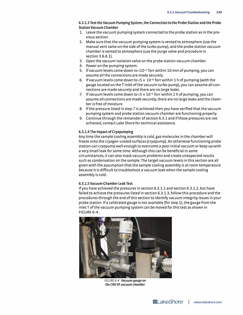
6.3.1 Vacuum Troubleshooting 139
6.3.1.3 Test the Vacuum Pumping System, the Connection to the Probe Station and the Probe Station Vacuum Chamber 1. Leave the vacuum pumping system connected to the probe station as in the pre-
vious section. 2. Make sure that the vacuum pumping system is vented to atmosphere (use the
manual vent valve on the side of the turbo pump), and the probe station vacuum chamber is vented to atmosphere (use the purge valve and procedure in section 3.6.6.1).
3. Open the vacuum isolation valve on the probe station vacuum chamber. 4. Power on the pumping system. 5. If vacuum levels come down to <10-2 Torr within 10 min of pumping, you can
assume all the connections are made securely. 6. If vacuum levels come down to <5 × 10⁻⁴ Torr within 1 h of pumping (with the
gauge located on the T inlet of the vacuum turbo pump), you can assume all con-nections are made securely and there are no large leaks.
7. If vacuum levels come down to <5 × 10⁻⁵ Torr within 2 h of pumping, you can assume all connections are made securely, there are no large leaks and the cham-ber is free of moisture.
8. If the pressure listed in step 7 is achieved then you have verified that the vacuum pumping system and probe station vacuum chamber are functioning properly.
9. Continue through the remainder of section 6.3.1 and if these pressures are not achieved, contact Lake Shore for technical assistance.
6.3.1.4 The Impact of CryopumpingAny time the sample cooling assembly is cold, gas molecules in the chamber will freeze onto the cryogen-cooled surfaces (cryopump). An otherwise functioning probe station can cryopump well enough to overcome a poor initial vacuum or keep up with a very small leak for some time. Although this can be beneficial in some circumstances, it can also mask vacuum problems and create unexpected results such as condensation on the sample. The target vacuum levels in this section are all given with the assumption that the sample cooling assembly is at room temperature because it is difficult to troubleshoot a vacuum leak when the sample cooling assembly is cold.
6.3.1.5 Vacuum Chamber Leak TestIf you have achieved the pressures in section 6.3.1.1 and section 6.3.1.2, but have failed to achieve the pressures listed in section 6.3.1.3, follow this procedure and the procedures through the end of this section to identify vacuum integrity issues in your probe station. If a calibrated gauge is not available (for step 1), the gauge from the inlet T of the vacuum pumping system can be moved for this test as shown in FIGURE 6-4 .
FIGURE 6-4 Vacuum gauge on the CRX-VF vacuum chamber
| www.lakeshore.com
140 cHAPTER 6: Maintenance and Troubleshooting
1. Install a vacuum gauge to the available NW 25 gauge port on the vacuum cham-ber or on the chamber side of the vacuum isolation valve. The NW 40 Tee from the TPS FRG may be placed between the vacuum isolation valve and the chamber as shown in FIGURE 6-4.
2. Pump out the vacuum chamber as described in section 4.4.2. 3. Allow the pump to run for 2 h. 4. Log the gauge reading at the chamber. 5. If the system did not reach <10-3 Torr, refer to section 6.3.1.6 to section 6.3.1.8. 6. Close the vacuum isolation valve. 7. Turn off the vacuum pump and vent the turbo. 8. Wait 10 min; compare the gauge reading at the chamber to the reading recorded
in step 4. If the reading is more than one order of magnitude above the reading recorded in step 4, or the pressure reading continues to rise rapidly, there may be a leak in the vacuum chamber.
6.3.1.6 Will Not Achieve 10-2 TorrIf the system will not achieve at least 10-2 Torr in the vacuum chamber, the problem is likely mechanical and should be relatively easy to identify. Follow this procedure to find the issue.
D Open and fully close the purge valve; purge valve seats sometimes do not fully close
D Close the turbo vent valve if it is not closed automaticallyD Visually inspect the pressure relief valve to verify that it is properly seatedD Check the alignment of the vacuum chamber lidD Verify that the chamber lid o-ring is properly seatedD Verify that the seals and clamps are properly installed on the vacuum lineD Examine any changes that were made to the system since it was last used to
verify that the system was reassembled properlyD Look for any parts that may have been damaged, including bellows, vacuum line,
valves, fittings, etc.
6.3.1.7 Will Not Achieve 10-3 TorrSystems achieving between 10-2 Torr and 10-3 Torr in the vacuum chamber can be more difficult to troubleshoot because these smaller leaks can be hidden.
D Examine any changes that were made to the system since it was last used (especially removal of probe arm assemblies) to verify that the system was reassembled properly. Remove, clean, inspect for damage, grease, and reinstall o-rings that were used in the change.
D Remove, clean, inspect for damage, grease, and reinstall the vacuum chamber lid o-ring. Make sure the o-ring is not twisted.
D Check the torque on fasteners between the bellows and arm base; see section 5.3.4. Do not overtighten these fasteners or new leaks can be created.
D As an aid in identifying the source of the leak, place a few drops of isopropyl alcohol on the suspected area and look for an observable change in the vacuum gauge reading.
6.3.1.8 Will Not Achieve Less Than 10-3 Torr or Cool to Base TemperatureSystems capable of achieving 10-3 Torr, but unable to achieve and hold between 3 × 10⁻⁴ Torr and 9 × 10⁻⁴ Torr or unable to cool to the specified base temperature, are the most difficult to troubleshoot, because the symptom can be caused by several different problems. Contamination in the vacuum chamber and very small leaks are the most common issues associated with this level of performance.
Suspect contamination if:
D The system has been left open for extended periods of timeD The system has been worked on and good vacuum practices were not followed
Model CRX-VF Probe Station
6.3.2 CCR Troubleshooting 141
D The system has been overheated or operated when not under vacuumD The system has been vented to atmosphere while cold
To minimize the effects of contamination:
D Follow the guidelines in section 6.2.3D Follow the guidelines in section 6.2.12
Suspect a very small leak if:
D The pump passed a blank off testD The system is clean and poor vacuum persistsD Performance degrades the longer the system is coldD Sudden changes in vacuum reading are observed when the sample stage is
heated, especially warming above 77 K
The best way to proceed if you suspect a leak:
D Follow the instructions in section 6.3.1.7 in hopes of sealing the system even if the exact source is not identified
D Replace any o-rings that look worn or flattened D Clean and re-grease the o-rings between the probe arm base and bellows,
especially if the leak increases when planarization adjustments are made D If the pressure relief valve assembly activates routinely, verify that it
reseats properly
Never operate the probe station without a pressure relief valve installed.
If these troubleshooting procedures do not correct the problem, a helium leak detector will be required to identify the exact source of the leak.
6.3.2 CCR Troubleshooting
This section provides steps to take if the CRX-VF CCR compressor and cold head are not working properly. Additional information may be found in the SRDK Series Cryocooler Operation Manual. The instructions below assume you have the standard F-70 water cooled compressor configured with the CRX-VF, but these instructions can be used as a guide for troubleshooting alternate compressor configurations.
6.3.2.1 CCR Compressor Will Not StartIf the CCR compressor will not start, suspect the following:
D The 3-phase power is not turned on to the CCR compressor D The CCR compressor circuit protector needs to be reset. Refer to the F-70
Compressor Unit Technical Instruction section 3-1-2 for instructions on resetting the circuit protector. Be sure to follow all safety precautions described in that manual.
6.3.2.2 CCR Compressor Starts But Then Shuts DownIf the CCR compressor will start, but after a period of time it shuts down, suspect the following:
D If the CCR compressor starts for approximately 30 s and then shuts off, suspect a phase reversal of the input 3-phase power leads. The CCR compressor is provided with a phase reverse protection circuit for the input power and will shut down for protection if the phasing is not in the proper order. If this is the problem, changing position of any two of the three 3-phase connections will rectify the phasing.
Three-phase wiring changes should be completed by a qualified electrician. Ensure that the customer facility 3-phase power is off to the CCR compressor and adhere to all local codes and standards. Failure to comply may result in injury or death.
| www.lakeshore.com
142 cHAPTER 6: Maintenance and Troubleshooting
D If the CCR compressor starts for approximately 2 min to 3 min and then shuts off, and one of the three OVER TEMP lights are illuminated on the CCR compressor control panel, suspect that either the cooling water is not on or not cool enough, or that the ambient air temperature is too high. Refer to section 3.2.4 for the water cooling and the ambient air requirements to verify that they are being met. Adjust the temperature as necessary.
D If the CCR compressor starts for 30 s and runs up to 10 min before shutting down, suspect that the CCR has low helium pressure due to a helium leak. With this scenario, as the helium depletes, the amount of time it takes for the CCR compressor to shut down will get shorter. Consult the SRDK series cryocooler manual section 4-2 or contact Lake Shore for technical assistance.
6.3.3 Probe Station Cooling Troubleshooting
Many probe station cooling issues are actually symptoms of vacuum problems. It is advisable to review section 6.3.1 before proceeding with this section. The most common sample cooling assembly cooling problems are listed below.
6.3.3.1 Probe Station Does Not Begin to CoolUse this section if the CRX-VF stages do not begin to cool. The first step is to make sure that all temperature controller heater loops are turned off or have a 0 K setpoint. If this has been verified, then the problem is more likely a problem with the CCR:
D Ensure that the CCR compressor is on and operating properlyD Ensure that the cold head electrical cable is connected to both the compressor
and the cold headD If the CCR compressor is operating but the cold head is not cooling the probe
station, stop operation and contact Lake Shore
6.3.3.2 Sample Stage Will Not CoolIf the magnet stage cools but the sample stage does not, verify that the sample stage temperature control output is off and the heat switch is in the Rad position.
If the sample stage temperature control is off and the heatswitch is in the Rad position, then your problem may be a result of a malfunction with the heat switch. Stop operation and contact Lake Shore.
6.3.3.3 Magnet Stage Will Not CoolIf the radiation shield stage cools, but the magnet stage does not cool, verify that the magnet stage temperature control output is off. If the magnet stage temperature control is off, then the problem may be the result of a malfunction with the CCR cold head 2nd stage. Stop operation and contact Lake Shore (section 6.5).
6.3.3.4 Radiation Shield Stage Will Not CoolIf the magnet stage cools but the radiation shield stage does not, verify that the radiation shield stage and the CCR 1st stage temperature control outputs are off. If the radiation shield stage temperature and the CCR 1st stage controls are off, then your problem may be a result of a malfunction with the CCR cold head first stage. Stop operation and contact Lake Shore.
Model CRX-VF Probe Station
6.3.3 Probe Station Cooling Troubleshooting 143
6.3.3.5 Sample Stage Does Not Reach Base TemperatureThe CRX-VF sample stage should be able to cool to within 1 K of base temperature in approximately 4.5 h. A large number of problems can prevent the sample stage from reaching base temperature, because every subsystem needs to be optimized simultaneously. Common problems are:
D The heatswitch is in the Open or Rad position.D The heatswitch is not seated properly: there is mechanical variation in the
heatswitch. Turn the heatswitch control knob several turns in the counterclockwise direction and then return it to full stop in the Base position.
D Poor vacuumD Probe arm position: placing probe arms in the fully retracted x-axis position
presents a greater heat load to the station, as more of the arm’s length will be outside of the radiation shielding; extend the probe arms into the probing area to reduce the heat load to achieve base temperature.
D Extra heat load on the sample stage: can be caused by arm braids touching improperly, temperature control heater left on, microscope light left on, or all probe arms positioned all the way out in the x-axis.
D Improper temperature controller setup: if the temperature controller inputs are reconfigured, it is common for the wrong temperature response curve to be selected for a sensor.
D Repeated thermal cycling of the sample stage without warming the system to room temperature will degrade base temperature operation. This is a common behavior of cryocoolers. Each time the sample stage is warmed above approximately 100 K and returned to base temperature, the base temperature will be slightly higher than what was achieved during initial cool down. Warm the entire probe station to room temperature (section 4.5.4) and cool again (section 4.5.2) to reestablish specified base temperature.
6.3.3.6 Takes Too Long to CoolFIGURE 6-5 illustrates a typical CRX-VF sample cooling assembly cooling curve with the heatswitch in the Rad position. The system cools slowly at first because the heat capacity of the materials is high near room temperature. As the materials cool, their heat capacity drops and the system cools more quickly. This impacts warm up time and temperature control time constants. At approximate time 4:35 the heatswitch is moved to the Base position.
If the cooling cycle takes significantly longer than the times represented in the cooling curve (FIGURE 6-5), investigate the possible causes listed in section 6.3.3.2 to section 6.3.3.5.
| www.lakeshore.com
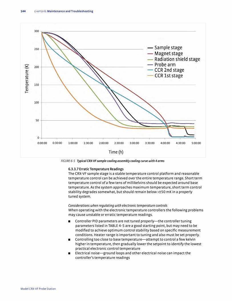
144 cHAPTER 6: Maintenance and Troubleshooting
6.3.3.7 Erratic Temperature ReadingsThe CRX-VF sample stage is a stable temperature control platform and reasonable temperature control can be achieved over the entire temperature range. Short term temperature control of a few tens of millikelvins should be expected around base temperature. As the system approaches maximum temperature, short term control stability degrades somewhat, but should remain below >±50 mK in a properly tuned system.
Considerations when regulating with electronic temperature controlsWhen operating with the electronic temperature controllers the following problems may cause unstable or erratic temperature readings.
D Controller PID parameters are not tuned properly—the controller tuning parameters listed in TABLE 4-5 are a good starting point, but may need to be modified to achieve optimum control stability based on specific measurement conditions. Heater range is important to tuning and also must be set properly.
D Controlling too close to base temperature—attempt to control a few kelvin higher in temperature, then gradually lower the setpoint to identify the lowest practical electronic control temperature
D Electrical noise—ground loops and other electrical noise can impact the controller’s temperature readings
FIGURE 6-5 Typical CRX-VF sample cooling assembly cooling curve with 4 arms
Model CRX-VF Probe Station
6.3.4 Magnet Troubleshooting 145
6.3.4 Magnet Troubleshooting
The superconducting magnet used in the CRX-VF is very reliable and practically maintenance free. It is designed to withstand frequent cooling cycles and even periodic quenches (the magnet wire changing from a superconducting state to a normal state when the magnet is charged) without damaging the magnet. Excessive quenching or icing, caused by venting the system while the magnet is cold, will shorten the service life of the magnet.
6.3.4.1 Magnet Power SupplyBefore going through an extensive troubleshooting process on the magnet, it is advisable to verify proper power supply operation. Disconnect the power supply from the probe station and place a short circuit across its output with 6 AWG copper wire. The Model 625 superconducting magnet power supply is capable of sourcing the maximum allowable current into a short circuit. If it does not, refer to information included in the Model 625 user’s manual.
6.3.4.2 Magnet Will Not ChargeThe following are the most common problems when a magnet will not charge:
Never attempt to troubleshoot the magnet with the magnet charged or power supply attached.
D Magnet is not cold—the superconducting magnet will not charge unless it is below 5 K in temperature. The resistance of the magnet wire is too high in its normal state for the power supply to provide any appreciable current.
D Power supply interlocks—there are a variety of limits and interlocks built into the Model 625 hardware and firmware for safety. Any of these that are set improperly will prevent the operator from charging the magnet. Please refer to the settings given in section 4.5.9.
D Magnet cabling—the high current cabling must be in place and tightly connected in order for the power supply to be able to charge the magnet. There is a safety screw that holds the connector in place. Make sure the screw is connected securely. With the power supply turned off, check to make sure all high current connections between the power supply and vacuum chamber are tight. The connections inside the vacuum chamber are not field serviceable.
D Damaged magnet—the superconducting magnet can be inspected from outside the vacuum chamber with a handheld digital multimeter (DMM).
With the power supply turned off and both the high current and voltage sense leads disconnected from the magnet, measure the resistance of the magnet from the external high current leads. The resistance should read near 0 ) when the magnet is below 5 K. The resistance should read between 900 ) and 1300 ) when the magnet is at room temperature. If your readings are in these specifications, the magnet is not likely the problem.
Choose a meter that uses less than 100 µA of excitation current on the resistance measurement. Higher excitations may cause the protection diodes to interfere with the reading.
If the other troubleshooting steps do not indicate another problem and a damaged magnet is suspected, please contact Lake Shore service or your local representative for assistance (section 6.5). Superconducting magnets cannot be serviced in the field.
| www.lakeshore.com
146 cHAPTER 6: Maintenance and Troubleshooting
6.3.4.3 Magnet QuenchesQuenches should be rare when the CPX-VF is operated as described in this manual. Check the following if periodic quenching is experienced:
D Magnet stage too warm—the magnet will quench if it is too warm. Lake Shore recommends operating it below 5 K. It may be necessary to operate colder on some magnets, depending on the application.
D Poor vacuum—can cause the magnet to quench even if the temperature sensor reads below 5 K. Refer to section 6.3.1.
D Ramping too fast—the magnet will quench any time the maximum ramp rate is exceeded. See section 4.6.1 for maximum ramp rates.
D Exceeding the maximum current—the magnet will quench any time the maximum current is exceeded. See section 4.6.1 for maximum current.
D Improper power supply settings—a quench can be reported by the power supply even when one does not occur if the quench limit is not set properly. See section 4.6.1 to verify your quench limit.
6.3.5 Image System Troubleshooting
Establishing a high quality sample image can be difficult the first time the probe station is set up or after it has been reconfigured if the proper setup is not followed. The electrical, mechanical and optical components of the vision system must all be working together properly for the vision system to perform as expected. This section will help identify which part of the vision system is causing the undesirable symptom so it can be remedied.
6.3.5.1 No ImageIf there is no image on the monitor at all, the problem is likely electrical. It is important to remember that the camera, light source and monitor are independent components and have separate power supplies and power switches.
D Remove lens cover if presentD Verify the camera, light source and monitor are all powered and turned onD Turn the light source to 50% outputD Verify that the s-video cable between the camera and monitor is plugged inD Verify the monitor source is set to the s-video input
If the problem is not identified with these steps, press the set (setup) button on the camera. If the setup menu appears on the monitor, the problem is likely in the optics rather than the electronics. The following sections may help identify the problems with image system optics.
6.3.5.2 Insufficient Sample IlluminationTypically no more than 50% to 70% of the maximum light source setting is required to properly illuminate the sample. If a higher output is required or the sample remains too dark at 100% output, the light source may be out of alignment. To verify proper alignment, do the following:
D Turn off the light source and allow it to coolD Remove the fiber optic bundle from the light source D Remove any dust on the end of the fiber optic bundleD Check that the bulb is centered in the opening
If the bulb is out of alignment, refer to the light source manual for further information.
Do not lower or raise the microscope trying to improve illumination. This will bring the sample out of the focal range of the microscope.
Model CRX-VF Probe Station
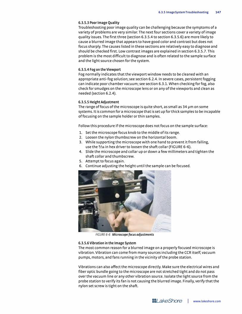
6.3.5 Image System Troubleshooting 147
6.3.5.3 Poor Image QualityTroubleshooting poor image quality can be challenging because the symptoms of a variety of problems are very similar. The next four sections cover a variety of image quality issues. The first three (section 6.3.5.4 to section 6.3.5.6) are more likely to cause a blurred image that appears to have good color and contrast but does not focus sharply. The causes listed in these sections are relatively easy to diagnose and should be checked first. Low contrast images are explained in section 6.3.5.7. This problem is the most difficult to diagnose and is often related to the sample surface and the light source chosen for the system.
6.3.5.4 Fog on the ViewportFog normally indicates that the viewport window needs to be cleaned with an appropriate anti-fog solution; see section 6.2.4. In severe cases, persistent fogging can indicate poor chamber vacuum; see section 6.3.1. When checking for fog, also check for smudges on the microscope lens or on any of the viewports and clean as needed (section 6.2.4).
6.3.5.5 Height AdjustmentThe range of focus of the microscope is quite short, as small as 34 µm on some systems. It is common for a microscope that is set up for thick samples to be incapable of focusing on the sample holder or thin samples.
Follow this procedure if the microscope does not focus on the sample surface:
1. Set the microscope focus knob to the middle of its range. 2. Loosen the nylon thumbscrew on the horizontal boom. 3. While supporting the microscope with one hand to prevent it from falling,
use the 3/bg in hex driver to loosen the shaft collar (FIGURE 6-6). 4. Slide the microscope and collar up or down a few millimeters and tighten the
shaft collar and thumbscrew. 5. Attempt to focus again. 6. Continue adjusting the height until the sample can be focused.
6.3.5.6 Vibration in the Image SystemThe most common reason for a blurred image on a properly focused microscope is vibration. Vibration can come from many sources including the CCR itself, vacuum pumps, motors, and fans running in the vicinity of the probe station.
Vibrations can also affect the microscope directly. Make sure the electrical wires and fiber optic bundle going to the microscope are not stretched tight and do not pass over the vacuum line or any other vibration source. Isolate the light source from the probe station to verify its fan is not causing the blurred image. Finally, verify that the nylon set screw is tight on the shaft.
FIGURE 6-6 Microscope focus adjustments
| www.lakeshore.com

148 cHAPTER 6: Maintenance and Troubleshooting
Vibration from vacuum pumps: vacuum pumps used with the probe station are a likely candidate for vibration because they are in close proximity to the probe station and are connected through stainless steel lines that transfer vibration. Vacuum pumps and lines can be easily identified as the source of vibration by observing the microscope image when the pumps are off and lines disconnected. If a pump or line is identified as a problem and it cannot be disconnected during operation, the PS-PLVI-40 pump line vibration isolation option is recommended.
Vibration from infrastructure: if the vibration is intermittent, it may be due to infrastructure sources such as HVAC systems or elevators. In this case, make sure that the inner CCR stand and outer probe station stand are properly installed and aligned. If the system did not include active vibration isolation, it should be considered.
6.3.5.7 Poor Contrast ImagesThis section addresses images that are poor in contrast, show little or no sample definition and have little response to small changes in light intensity. This problem is difficult to troubleshoot primarily because of the geometry of the CRX-VF itself. The relatively long distance between microscope and sample and two optic viewports in between offer significant challenges to conventional image systems. Because of this, the light source and sample surface can have a big impact on image quality.
The first step to remedy the problem is to eliminate other possibilities. The steps below assume you have warmed the system to room temperature.
1. Using the camera setup menu, reset the camera controls to their factory preset values.
2. Remove the vacuum chamber lid and radiation shield lids. 3. Re-establish the sample image with the lids off.
This should provide an image with very high quality and contrast. If it does not, go back through the assembly procedures, section 3.5.5, and the earlier parts of section 6.3.5 and try to identify the problem.
The image obtained with the chamber and shield lids off is better than can be expected with them on. The viewport optics will always degrade image quality no matter how well the system is optimized.
Experiment with different sample materials first with the lids off, then add the lids back on one at a time. First try a very reflective sample such as a piece of polished silicon wafer. Then experiment with a sample that absorbs light. Finally, try a sample that has high contrast and image on the three dimensional details in the sample holder itself. This investigation will establish the limits in capability of the probe station and its configuration of microscope and light source.
Optimize the light intensity and camera settings for the type of sample most commonly tested in the probe station. If the results do not meet expectations for the equipment purchased, contact Lake Shore service for assistance (section 6.5).
6.3.5.8 Image OrientationFollow this procedure to change the orientation of your image:
1. Below the threaded joint to the CCD camera is a rotating joint. Using a 5/ge in hex driver, loosen the three set screws on this joint (FIGURE 6-7).
2. Rotate the camera so the image on the monitor is oriented logically. The objective is to rotate the camera until the monitor image corresponds to the expected image (the bottom left probe appears in the bottom left of the monitor screen).
3. Retighten the set screws after adjustment.
Model CRX-VF Probe Station

6.3.6 Probe Troubleshooting 149
6.3.6 Probe Troubleshooting
The three most common issues that arise with probes fall in three categories: bent or broken probe tips, poor or non-ohmic electrical contact, or a loss of continuity.
6.3.6.1 Bent or Broken Probe TipsProbe tips by nature are delicate and must be handled with care both inside and outside the probe station. The following are ways that probe tips can be broken or bent:
Landing: landing probes is probably the most important step in achieving reliable, repeatable electrical measurements. Too little contact pressure will result in unstable measurements, but too much will damage probes. ZN50 probe tips damaged during landing are often bent upwards. Carefully follow instructions in section 4.6.2 to prevent probe damage. Develop and follow a protocol suitable for the combination of probe type and pad material used in each application.
Failing to raise the probe tips: the cautions throughout this manual instruct operators to raise probe tips before cooling or warming the system, when applying vacuum, and when moving probes in the x or y direction. Probes that are damaged when vacuum is applied or while being moved when landed are generally the ones that are very severely damaged. Probes damaged during temperature change often take on a characteristic curled shape. Wait for the probe arm temperature to stabilize, approximately 10 to 15 min after the radiation shield stage stabilizes, before landing the probes.
Storing: when probes are not being used, store them in their original packaging. This is especially important for microwave probes, because the weight of the probe body will cause damage to the tip if the probe is left loose. Cleaning: aggressive cleaning can easily damage probes. If more than periodic tarnish removal for the BeCu ZN50 probes is necessary, it is recommended to gently clean the probe tips under a microscope, working away from the probe body.
6.3.6.2 Poor or Non-Ohmic Electrical ContactThere are several important considerations for assuring good electrical contact between the probe and sample:
FIGURE 6-7 Loosening the camera rotating joint to adjust the camera image orientation
| www.lakeshore.com
150 cHAPTER 6: Maintenance and Troubleshooting
Pressure: appropriate contact pressure is required for both establishing and maintaining good contact. Too little pressure may result in high contact resistance, resistance that changes significantly with time or is overly sensitive to vibrations. Too much pressure will obviously cause probe damage. One way to ensure repeatable contact pressure is to monitor the distance the probe tip skates when being landed as described in section 4.6.2. This distance is likely different for each different probe material, tip radius and sample material. Another approach is to monitor the DC resistance of each pair of probes while landing.
Tip radius: a larger tip radius normally provides a larger area of contact, which consequently lowers contact resistance. The larger tip can also tolerate slightly higher pressure before being damaged. Smaller tips are normally chosen for probing smaller features, but they can also be useful in scratching through electrically insulating oxide layers that may form on the sample surface. For more information, please reference section 2.6.3.
Tip material: Lake Shore offers several tip materials for different applications. Not every tip material is compatible with every sample material. For more information, please reference section 2.3.2.1.
Dirty or damaged tips: some tip materials, especially BeCu, form an insulating oxide when exposed to air. Tips also get dirty during normal use. Bent or damaged tips generally make very poor electrical contact. Clean and inspect probe tips for damage regularly. For more information, please reference section 6.2.7.
Temperature change: probe arms change length when their temperature changes, necessitating lifting probe tips before changing temperature. The probe arms must stabilize in temperature for approximately 10 to 15 min (in addition to the sample stage) before probes can be landed effectively. If probes are landed too soon, the position of the probe tip will shift, degrading the quality of electrical contact.
6.3.6.3 Loss of ContinuityLoss of continuity is nearly always caused by bad contact between the probe tip and sample. If the contact resistance is known to be good and there is no continuity between the signal connector and the probe, the cause is likely a broken center conductor in the probe cable. This is often caused when the back of the SMA plug on the cryogenic coaxial cable is not held steady when the ZN50 probe is installed. Check the continuity of the center conductor by measuring the resistance between the center pin of the signal connector and the center of the SMA connector. If the resistance is not approximately zero, the cable must be replaced. Refer to section 5.3.5 for the procedure to replace the cable.
Model CRX-VF Probe Station

6.4 Service Reference 151
6.4 Service Reference
This is the service reference section.
6.4.1 Power Requirements and Power Configuration Information
Electrical power is required for the operation of the instrument console, vision system, turbo pumping system and CCR compressor. Most equipment is designed to operate over a range of line voltages. Some equipment must be configured to operate at a specific voltage within the range listed. This equipment is pre-configured at Lake Shore to the voltage specified when it is ordered. If the probe station is to be operated using a voltage other than the original configuration, some items may be reconfigured in the field while others may not. In addition, some items operate over the entire voltage range without modification. Field configurable options are indicated in TABLE 6-2. Refer to the equipment’s user manual for more information.
Item Voltage ranges (VAC)Voltage
tolerancePower
(W)Frequency range (Hz)
Voltage input field configurable?
Instrument console
Model 336 temperature controllers
100120220240
+6% -10% 250 50 to 60 Yes
Lake Shore Model 625 superconducting magnet power supply
100120220240
+6% -10% 850 50 to 60 Yes
Vision system
Viewera V172SV monitor 100 to 240 — 432 50 to 60 Universal
CCD camera 100 to 240 — 96 47 to 63 Universal
A20500 light source 100 to120—
190 50 to 60 No
A20510 light source 220 to 240 50 to 60
Turbo pumping system
TPS compact100 to 120200 to 240
— 260 50 to 60 No
CCR F-70L 200 +6% -10% 8300 50 to 60 No
F70-H
380400415 +6% -10%
7200 50 Yes
460480
8300 60 Yes
TABLE 6-2 Detailed power requirements
| www.lakeshore.com
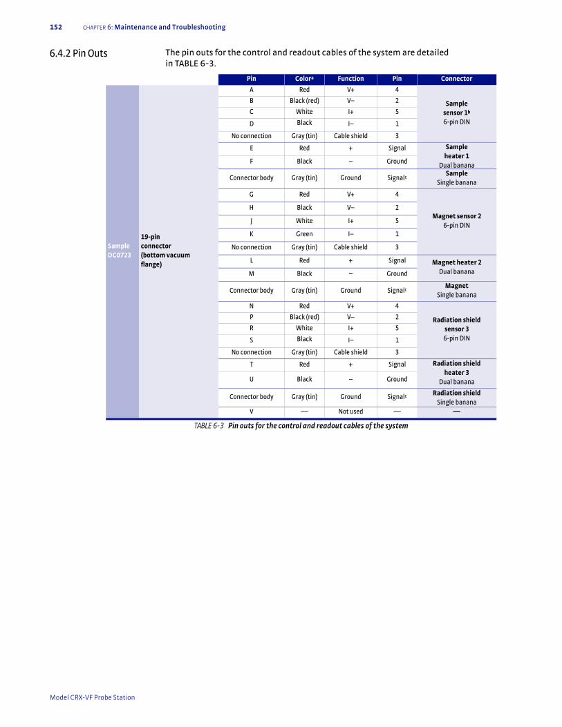
152 cHAPTER 6: Maintenance and Troubleshooting
6.4.2 Pin Outs The pin outs for the control and readout cables of the system are detailed in TABLE 6-3.
Pin Colora Function Pin Connector
Sample DC0723
19-pin connector (bottom vacuum flange)
A Red V+ 4
Sample sensor 1b
6-pin DIN
B Black (red) V– 2
C White I+ 5
D Black I– 1
No connection Gray (tin) Cable shield 3
E Red + Signal Sample heater 1
Dual bananaF Black – Ground
Connector body Gray (tin) Ground SignalcSample
Single banana
G Red V+ 4
Magnet sensor 26-pin DIN
H Black V– 2
J White I+ 5
K Green I– 1
No connection Gray (tin) Cable shield 3
L Red + Signal Magnet heater 2Dual bananaM Black – Ground
Connector body Gray (tin) Ground SignalcMagnet
Single banana
N Red V+ 4
Radiation shieldsensor 36-pin DIN
P Black (red) V– 2
R White I+ 5
S Black I– 1
No connection Gray (tin) Cable shield 3
T Red + Signal Radiation shieldheater 3
Dual bananaU Black – Ground
Connector body Gray (tin) Ground Signalc Radiation shieldSingle banana
V — Not used — —
TABLE 6-3 Pin outs for the control and readout cables of the system
Model CRX-VF Probe Station

6.4.3 Instrumentation Wiring Diagram 153
6.4.3 Instrumentation Wiring Diagram
FIGURE 6-8 shows the system wiring diagram. It details the electrical interconnec-tions between the probe station and instrument console. Lake Shore part numbers of individual cables are also shown. Contact Lake Shore if you need replacement cables.
CCRDC0922
19-pin connector (CCR vacuum shroud)
A Red V+ 4
CCR second stage sensor 16-pin DIN
B Black (red) V– 2
C White I+ 5
D Black I– 1
No connection Gray (tin) Cable shield 3
E Red + Signal CCR second stage heater 1
Single bananaF Black – Ground
Connector body Gray (tin) Ground SignalbCCR second stage
Single banana
G Red V+ 4
CCR first stagesensor 26-pin DIN
H Black (red) V– 2
J White I+ 5
K Black I– 1
No connection Gray (tin) Cable shield 3
L Red + Signal CCR first stageheater 2
Single bananaM Black – Ground
Connector body Gray (tin) Ground Signalb CCR first stageSingle banana
N to S — Not used — —
No connection Gray (tin) Not used —
T to V — Not used — —
Connector body Gray (tin) Not used — —
DC0616
Probe arm 6-pin connector
A Red V+ 4
Probe arm sensor
6-pin DIN
B Black (red) V– 2
C White I+ 5
D Black I– 1
No connection Gray (tin) Cable shield 3
E–F — Not used — —
a. In control cable b. Drain wire connected to single banana, which plugs into chassis next to heater output of controller. The other end of the drain wire is connected
TABLE 6-3 Pin outs for the control and readout cables of the system
| www.lakeshore.com
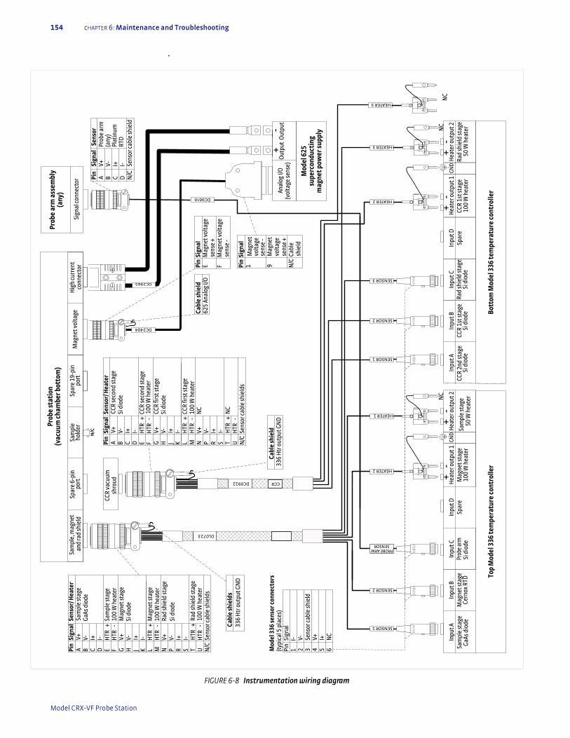
154 cHAPTER 6: Maintenance and Troubleshooting
.
FIGURE 6-8 Instrumentation wiring diagram
DL0723
Pin
Sign
alSe
nsor
/ Hea
ter
AV+
Sam
ple
stag
eB
V-Ga
As d
iode
CI+
DI-
EH
TR+
Sam
ple
stag
eF
HTR
-10
0 W
hea
ter
GV+
Mag
net s
tage
HV-
Si d
iode
JI+
KI-
LH
TR+
Mag
net s
tage
MH
TR-
100
W h
eate
rN
V+Ra
d sh
ield
stag
eSi
dio
deP
V-R
I+S
I-T
HTR
+Ra
d sh
ield
stag
e10
0 W
hea
ter
UH
TR-
N/C
Sens
or ca
ble
shie
lds
Sam
ple,
mag
net
and
rad
shie
ld
Cabl
e sh
ield
336
Htr
out
put G
ND
Pin
Sign
alSe
nsor
AV+
BV-
CI+
DI-
N/C
Sens
or ca
ble
shie
ld
N/C
CCR
vacu
umsh
roud
Spar
e 6-
pin
port
Sam
ple
hold
erSp
are
19-p
inpo
rtSi
gnal
conn
ecto
r
Prob
e ar
m a
ssem
bly
(any
)
Inpu
t BM
agne
t sta
geCe
rnox
RTD
Hea
ter o
utpu
t 1M
agne
t sta
ge
100
W h
eate
r
Hea
ter o
utpu
t 2
50 W
hea
ter
Inpu
t CPr
obe a
rmSi
dio
de
Inpu
t DSp
are
Mod
el 3
36 se
nsor
con
nect
ors
(typ
ical
5 p
lace
s)Pi
nSi
gnal
1I-
2V-
3Se
nsor
cabl
e sh
ield
4V+
5I+
6N
C
Inpu
t ASa
mpl
e st
age
GaAs
dio
de
SENSOR 2
SENSOR 1
SENSOR 1
+-
HEATER 2
+-
Top
Mod
el 3
36 te
mpe
ratu
re c
ontr
olle
r
SENSOR 2
GND
DC0616
PROBE ARM SENSOR
HEATER 1
HEATER 2
HEATER 3
DC0922
Prob
e st
atio
n (v
acuu
m c
ham
ber b
otto
m)
NC
Inpu
t BCC
R 1s
t sta
geSi
dio
de
Hea
ter o
utpu
t 1CC
R 1s
t sta
ge
100
W h
eate
rRa
d sh
ield
stag
e 50
W h
eate
r
Hea
ter o
utpu
t 2In
put C
Rad
shie
ld st
age
Si d
iode
Inpu
t DSp
are
Inpu
t ACC
R 2n
d st
age
Si d
iode
+-
+-
Bott
om M
odel
336
tem
pera
ture
con
trol
ler
GND
CCR
SENSOR 3Sa
mpl
e st
age
Prob
e ar
m
(any
) Pl
atin
um
RTD
Cabl
e sh
ield
s33
6 H
tr o
utpu
t GN
D
NC
HEATER 3
NC
Pin
Sign
alSe
nsor
/ Hea
ter
AV+
CCR
seco
nd st
age
BV-
Si d
iode
CI+
DI-
EH
TR+
CCR
seco
nd st
age
FH
TR-
100
W h
eate
rG
V+CC
R fir
st st
age
HV-
Si d
iode
JI+
KI-
LH
TR+
CCR
first
stag
eM
HTR
-10
0 W
hea
ter
NV+
NC
PV-
RI+
SI-
TH
TR+
NC
UH
TR-
N/C
Sens
or ca
ble
shie
lds
Mag
net v
olta
geH
igh
curr
ent
conn
ecto
r
Anal
og I/
O(v
olta
ge se
nse)
Out
put
DC2404
Cabl
e sh
ield
625
Anal
og I/
OPi
nSi
gnal
EM
agne
t vol
tage
sens
e +
FM
agne
t vol
tage
se
nse
-
DC2965
+-
Out
put
Pin
Sign
al1
Mag
net
volta
gese
nse
-9
Mag
net
volta
gese
nse
+N
/CCa
ble
shie
ldM
odel
625
su
perc
ondu
ctin
g m
agne
t pow
er su
pply
Model CRX-VF Probe Station
6.5 Technical Inquiries 155
6.5 Technical Inquiries
Refer to the following sections when contacting Lake Shore for application assistance or product service.
6.5.1 Contacting Lake Shore
The Lake Shore Systems Service department is staffed Monday through Friday between the hours of 8:00 AM and 5:00 PM EST, excluding holidays and company shut down days.
Contact Lake Shore Systems Service through any of the means listed below. However, the most direct and efficient means of contacting is to complete the online service request form at http://www.lakeshore.com/sup/serf.html. Provide a detailed description of the problem and the required contact information. You will receive a response within 24 hours, or the next business day in the event of weekends or holidays.
If you wish to contact Systems Service by mail or telephone, use the following:
Lake Shore Cryotronics, Inc.575 McCorkle Blvd.Westerville, Ohio 43082 USAPhone: 614-891-2243 (option 6)Fax: 614-818-1608e-mail: [email protected]
6.5.2 Return of Equipment
The probe station is packaged to protect it during shipment. Please use reasonable care when removing it from its protective packaging and inspect the probe station carefully for damage. If it shows any sign of damage, please file a claim with the carrier immediately. Do not destroy the shipping container; it will be required by the carrier as evidence to support claims. Call Lake Shore for return and repair instructions.
All equipment returns must be approved by a member of the Lake Shore Systems Service department. The service engineer will use the information provided in the service request form and will issue a Return Material Authorization (RMA). Once the RMA has been approved, you will receive appropriate documents and instructions for shipping the equipment to Lake Shore.
You will be given an RMA number. This number is necessary for all returned equipment. It must be clearly indicated on both the shipping carton(s) and any correspondence relating to the shipment.
The user should retain any shipping carton(s) in which equipment is originally received, in the event that any equipment needs to be returned.
6.5.3 RMA Valid Period RMAs are valid for 60 days from issuance; however, we suggest that equipment needing repair be shipped to Lake Shore within 30 days after the RMA has been issued. You will be contacted if we do not receive the equipment within 30 days after the RMA is issued. The RMA will be cancelled if we do not receive the equipment after 60 days.
6.5.4 Shipping Charges All shipments to Lake Shore are to be made prepaid by the customer. Equipment ser-viced under warranty will also be returned shipping prepaid by the customer. Equip-ment serviced out-of-warranty will be returned FOB Lake Shore.
6.5.5 Restocking Fee Lake Shore reserves the right to charge a restocking fee for items returned for exchange or reimbursement.
| www.lakeshore.com

156 cHAPTER 6: Maintenance and Troubleshooting
Model CRX-VF Probe Station

157 Index
Index
Aassembly 61
microscope 67pump line vibration isolator 72turbo pumping system 70, 84vision system 67
Bbake out
heated cycle purge 111BECU probe tips
cleaning 133
Ccables
adjusting semi-rigid cables 122installing semi-rigid 121removing coaxial cable 119removing semi-rigid 121ZN50 DC/RF cables 7
calibration substrate 26, 43CCR 12
closed cycle refrigerator 15cold head 14compressor control panel 97compressor default settings 97compressor maintenance 129control settings 105operation 97stages 14supply and return pressures 97vacuum shroud 13
coaxial cables, reconfiguration 119condensation 111
reducing 111connectors
microwave 41cooldown
probe considerations 76settings 105
DDC measurements 34DC/RF (ZN50) probe configurations 23DC/RF measurements 31
small signal low noise 36
Eelectrical measurements 31
voltage limits 40environmental requirements 49
Ffiber optic probe 23
probe arm modification 27
Ggas requirements 52ground loops 32grounded sample holder 27, 32, 34
cleaning 132grounding 31, 33
high impedance measurements 38instrument console 31vacuum chamber 31, 32
grounding, instrument console 31ground-signal-ground 7, 25, 40, 78guarding 38
configurations for 38
HHall 1
Iinstallation 47
coaxial cable 119microwave probes 78optical fiber 124probe arm and base 118semi-rigid cable 121translation stage 113
instrument console 18, 19, 20grounding 31power requirements 151unpacking 57verification 81wiring 153
Llanding the probe 108leakage
low leakage measurements 37leakage current 24, 37, 38
| www.lakeshore.com

158
light source 22, 69, 108image quality 148power requirements 50, 151troubleshooting 146
low resistance samples 37
Mmagnet 16magnet power supply
troubleshooting 145magnet power supply, charging the magnet 106magnetic field 106maintenance 129
probe arm 134vacuum pump 135
micro-manipulated stage 17, 23microscope 9, 22
assembly 67, 68blurred image 147coaxial light 29connections 68focus 83lights 29operation 108resolution 28ring light 29
microwavecables 7cables and connectors 26compatible cables 26compatible probes 25
microwave cablesconnectors 26
microwave connectors, images of 41microwave measurements 40
calibration 43contact quality 45frequency range 40microwave cables and connectors 40planarization 45
microwave probes 25care of 134, 149configurations 25handling 78image with cable 80installing 78removing 80specifications 4standard 25temperature 25
Model 336verifying 81verifying voltages 81
Model 625 20charging the magnet 106default settings 81power requirements 50, 151
Nnoise 49
electrical 144low noise measurements 36, 37reducing 50-60 Hz 32, 33reducing 50-60 Hz noise 33
Ooperation 85
advanced 111chamber lid removal 87closing the vacuum chamber and radiation
shield 92evacuating the vacuum chamber 95imaging and probing the sample 107landing the probe 108mounting samples 89mounting the sample holder 91planarization assembly 109probe arm translation stages 85reducing condensation 111removing the sample holder 88sample alignment 89sample exchange 87temperature 97temperature control 104temperature controls 97turbo pump 93turbo pump shut down 96vacuum 93vacuum chamber purge 96
optical fiber 124installing 124removing 124
optical specifications 4o-rings
maintenance 131
Model CRX-VF Probe Station

159 Index
Ppin outs 152planarization assembly 25
installation 126use 109
power requirements 501-phase 503-phase 50
probable area 86probe arm
assemblies 17installing 118maintenance 134removing 116
probe station 12applications 2assembly 61components 12description 1elevation requirements 48environmental requirements 49floor plan 48installation 47materials 2operation 85power requirements 50required equipment 6site requirements 47specifications 2standard equipment 5subsystems 11unpacking 53
probe tips 23probes 6
frequency range 4installing a ZN50 73landing 108misaligned 79pitch 25, 26, 42removing 73removing a ZN50 77troubleshooting 149
probing configurations 23purge
heated cycle purge 111
Rradiation shield lid removal 87RF measurements 34, 36
Ssafety considerations 9sample
imaging and probing 107low resistance 37permanent mounting 91semi-permanent mounting 90temporary mounting 90
sample cooling assembly 14, 85cooling curve 144cryopump 139electronic controls 105image 14troubleshooting 142vacuum controls 94
sample exchange 87sample holder 8, 27
alignment of sample 89cleaning 132coaxial 28device characterization 35grounded 27isolated 35isolated ground 27mounting samples 89probable area 86removing 88samples with conductive back side features 35specifications 4voltage biasing 35
service reference 151shielding 33
DC/RF measurements 33vacuum chamber 33
space requirements 47specifications 2superconducting magnet
diagram of 16fields 49, 106power supply 20troubleshooting 145
Ttemperature
instrumentation 19specifications 3
temperature control summary 104testing the system 81
microscope 83probe arm reach 83probe continuity 83sensor and heater 81
| www.lakeshore.com
160
triaxial sample holder 28troubleshooting 137
image system 146magnet 145probe station cooling 142probes 149
turbo pumping system 30basic operation 93components 22power requirements 50
Uunpacking 53
crates 55instrument console 57moving and lifting the probe station 54options 58tools required 54
Vvacuum chamber 13
cleaning 130closing the shields 92evacuating 95ground reference 31purging 96removing condensation 136shielding 33vacuum levels 95
vacuum gauge 22image of 71installing 71location 94
vacuum requirements 52vacuum troubleshooting 137Vector Network Analyzer 26, 43vibration 49, 62vibration isolation 72
low noise measurements 37viewport window maintenance 131vision system 22
assembly 67power requirements 151troubleshooting 146unpacking 57
voltage biasing 35, 39
Wwarm up
purging 96removing condensation 136sensors and heaters 14
water requirements 51wiring diagram 153
ZZN50 compatible probe cables 24ZN50 compatible probe mounts 25ZN50 probe tip material 23ZN50 probes 23
Model CRX-VF Probe Station