cs221: vhdl introduction · cs221: vhdl introduction dr. a. sahu dept of comp. sc. & engg....
TRANSCRIPT

CS221: VHDL Introduction
Dr. A. Sahu
Dept of Comp. Sc. & Engg.Dept of Comp. Sc. & Engg.
Indian Institute of Technology Guwahati
1

OutlineOutline
• Requirement of VHDL
• Model : Entity & Architecture
VHDL• VHDL–Basic language concepts, design methodology
• Online Demo in Class l–Examples, GHDL, GTKWAVE
2

VHDL TutorialVHDL Tutorial
• Forwarded By Frank Vahid: Digital Design• Forwarded By Frank Vahid: Digital Design
http://esd.cs.ucr.edu/labs/tutorial/
• Google search “VHDL Tutorial: Learn by• Google search VHDL Tutorial: Learn by Example”
3

Requirement of HDLRequirement of HDL• Time
– how the behavior of the system changes with timey g
– creating waveforms
• Periodic Signals : Clocks• Concurrency: Specify: Processes P1 and P2 execute in
parallelx = x + 1 y = a – b
P2
• Structure Composition and Interconnection:
P1 P2
• Structure, Composition and Interconnection:– Block A consists of two blocks: X1 and Y1 – Block X is duplicated
A BXXp
– Wire W connects A and B4
X1X1 Y1Y1 X2X2
A B
W

Requirement of HDLRequirement of HDL • Electrical Characteristics
– Current Levels Tri‐statingCurrent Levels, Tri stating– Sensitivity : Rising edge/falling edge
• Other programming constructsOther programming constructs– Text and File I/O, useful in simulation/debugging
• Bit‐true data typesit true data types–Not so important in SW, Important in HW– int<6:0> var; Specify the bit‐width of variablesint 6:0 var; Specify the bit width of variables
• Modules and Interfaces : – PortsInput Port P out Port W
5
Input Port P
Input Port Q
Input Port R
out Port W
Inout Port X

Fundamental VHDL ObjectsFundamental VHDL Objects
• Entity and Architecture Pair• Entity and Architecture Pair
Entity Represent
VHDL Model Entity
y p
External Interface
Consists of Two Parts
ArchitectureArch Represent Contents/FunctionArchitecture Contents/Function
ality
6

VHDL: EntityVHDL: Entity
• Entity : Represent External Interface• Entity : Represent External Interface
AA
BY Model
Name
ENTITY and_gate IS
PORT ( A IN BIT Port TypePORT ( A: IN BIT;B: IN BIT;Y: OUT BIT
Entity has Interface: No functionality
Port Type
P
7
);
END and_gate;
yPort Direction Port Name

VHDL: Architecture, Specifying f lfunctionality
C C d fl O d SARCHITECTURE data_flow OF and_gate IS
BEGIN
y <= a AND b;
END data_flow;
• May have multiple architectures for i igiven entity–different views–different levels of detail
8

Specifying ConcurrencySpecifying Concurrency• Concurrent Signal Assignments
+
Ci
Aii+
Ai
Bi
Si
ARCHITECTURE data flow OF full adder IS
Co
ARCHITECTURE data_flow OF full_adder IS
BEGIN
si <= ai XOR bi XOR ci;
co <= (ai AND bi) OR (bi AND ci) OR (ai AND ci);
9
co <= (ai AND bi) OR (bi AND ci) OR (ai AND ci);
END data_flow;
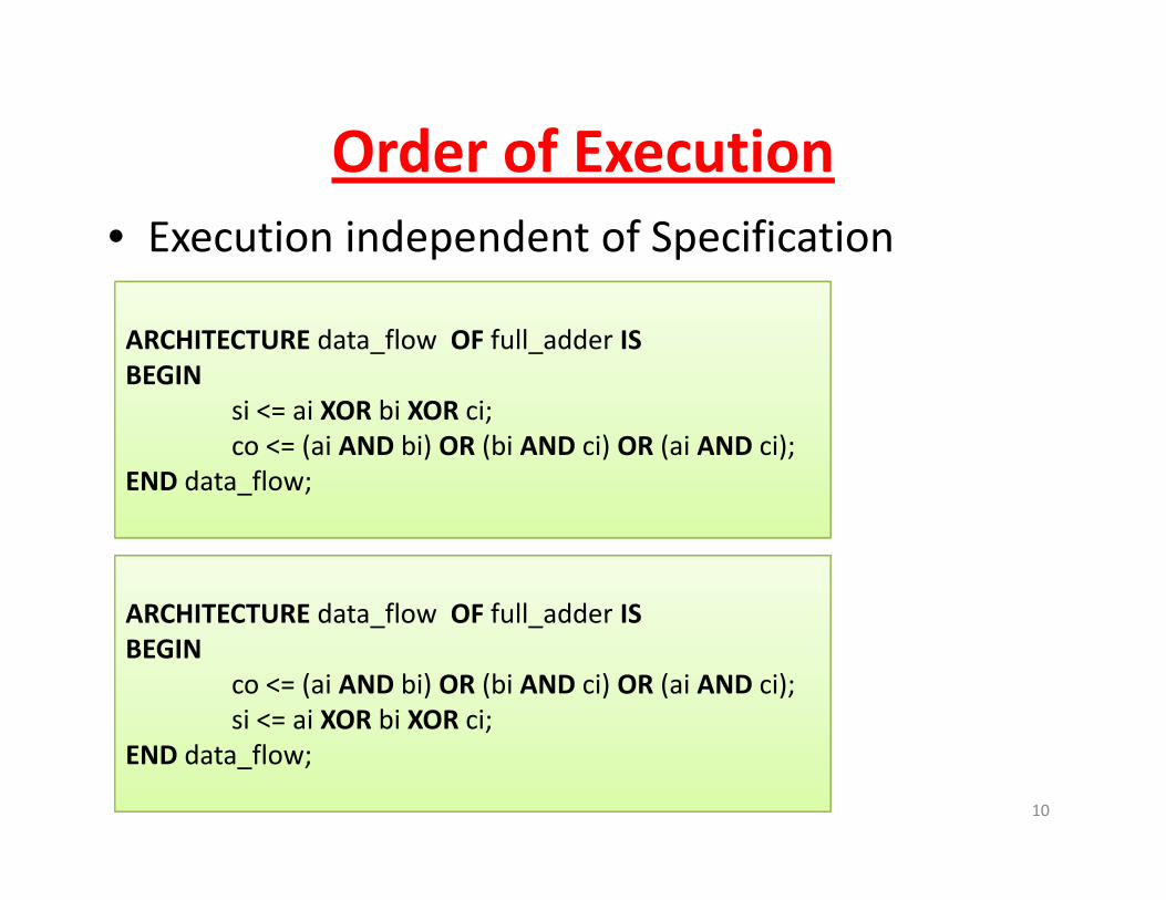
Order of ExecutionOrder of Execution• Execution independent of Specification
ARCHITECTURE data_flow OF full_adder IS
BEGIN
si <= ai XOR bi XOR ci;
co <= (ai AND bi) OR (bi AND ci) OR (ai AND ci);
END data_flow;
ARCHITECTURE data flow OF full adder ISARCHITECTURE data_flow OF full_adder IS
BEGIN
co <= (ai AND bi) OR (bi AND ci) OR (ai AND ci);
si <= ai XOR bi XOR ci;
10
END data_flow;

Modelling Combinational LogicModelling Combinational Logic• One concurrent assignment for each output
ARCHITECTURE data_flow
OF comb logic IS_ g
BEGIN
o1 <= i1 and i2;
o2 <= (i2 or i3) xor (i1 and i4);
i1
i2
o1
o2o2 <= (i2 or i3) xor (i1 and i4);
o3 <= ...;o4 <= ...;
i3
i4
o3
o4END data_flow;
11
When Logic Complexity IncreaseWhen Logic Complexity Increase
• Temporary SIGNALS neededTemporary SIGNALS needed
• Avoid redundant evaluations
g gX
Y=g (t)Y=g (f(x))
f
hf
g
h
Xt=f(x)
Z=h (f(x))
X
Z=h (t)h h
Ports : X,Y,Z Signal : t
12
Signal : t

SIGNALS• Represent intermediate wires/storage
• Internal ‐ not visible outside entityInternal not visible outside entity
ENTITY comb_logic IS
PORT (i1 i2 i3 i4: IN BIT;
ENTITY comb_logic IS
PORT (i1, i2, i3, i4: IN BIT;o1 o2: OUT BIT);PORT (i1, i2, i3, i4: IN BIT;
o1, o2: OUT BIT);END comb_logic;
o1, o2: OUT BIT);END comb_logic;
ARCHITECTURE d t fl 1
ARCHITECTURE data_flow
OF comb_logic IS
ARCHITECTURE data_flow1
OF comb_logic IS
SIGNAL temp: BIT;BEGIN
o1 <= (i1 and i2 and i3) xor i2;o2 <= (i1 and i2 and i3) or i4;
BEGIN
temp <= (i1 and i2 and i3);
o1 <= temp xor i2;
13
o2 < (i1 and i2 and i3) or i4;END data_flow;
o1 < temp xor i2;o2 <= temp or i4;
END data_flow;

SIGNALS
• executed when i1 i2• executed when i1, i2, or i3 changes
• executed when temp• executed when temp or i2 changes
• SIGNALS are
ARCHITECTURE data_flow1
OF comb_logic IS
SIGNAL temp: BIT;SIGNALS are associated with time/waveforms
SIGNAL temp: BIT;BEGIN
temp <= (i1 and i2 and i3);
o1 <= temp xor i2;/
• PORT is a special type of SIGNAL
o1 <= temp xor i2;o2 <= temp or i4;
END data_flow;
14

Modelling Delays: inertial delayModelling Delays: inertial delay• Models actual hardware
• Spikes suppressed
y <= INERTIAL NOT a AFTER 10 ns;y < INERTIAL NOT a AFTER 10 ns;y <= NOT a AFTER 10 ns; ‐‐ inertial delay is default
A
Y
0 10 12 22 30 35
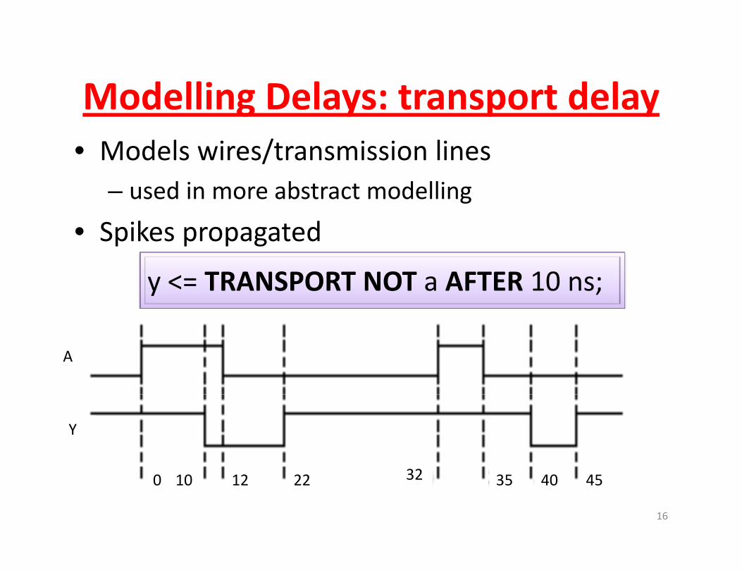
Modelling Delays: transport delayModelling Delays: transport delay• Models wires/transmission lines
– used in more abstract modelling
• Spikes propagated
y <= TRANSPORT NOT a AFTER 10 ns;
A
Y
16
0 10 12 22 32 35 40 45

Describing Behavior: ProcessesDescribing Behavior: Processes
• Signal assignment statements OK for simpleSignal assignment statements OK for simple behavior
• Complex behavior requires more constructs• Complex behavior requires more constructs– conditionals (IF, CASE)
l (FOR WHILE)– loops (FOR, WHILE)
• Use VHDL PROCESS
17

VHDL PROCESS
• PROCESS is sequential
ARCHITECTURE x of a ISBEGIN
f <= g+ 1;q
• Processes are concurrent w.r.t each other
p1: PROCESSBEGIN
f <= g+ 1;
• Signal assignment is a simple special caseA hit t i t f t
GIN
IF (x) THEN ...
ELSE ...;...
END PROCESS;• Architecture consists of a set of Processes (and signal assignments) at top level
END PROCESS;
p2: PROCESSBEGINg ) p
• Processes communicate using signals
FOR i in 1 TO 5 LOOPa (i) <= 0;ENDL LOOP;
18
END x;
ENDL LOOP;...END PROCESS;

PROCESS Execution SemanticsPROCESS Execution Semantics
• Need to define when Process is executedNeed to define when Process is executed– suspending/resuming execution
more complex than signal assignment– more complex than signal assignment
• (“evaluate when any signal on RHS changes”)
• No notion of “completion” of execution– needs to emulate hardware
19

Process Sensitivity ListProcess Sensitivity List• Process is sensitive to signals on Sensitivity List
ll d• All processes executed once at time=0
• Suspended at end of process
• Reactivated when event occurs on any signal in sensitivity list Sensitivity List = a by
PROCESS (a, b)
Sensitivity List = a, b
( , )
BEGIN
c <= a AND b;
20
END PROCESS;
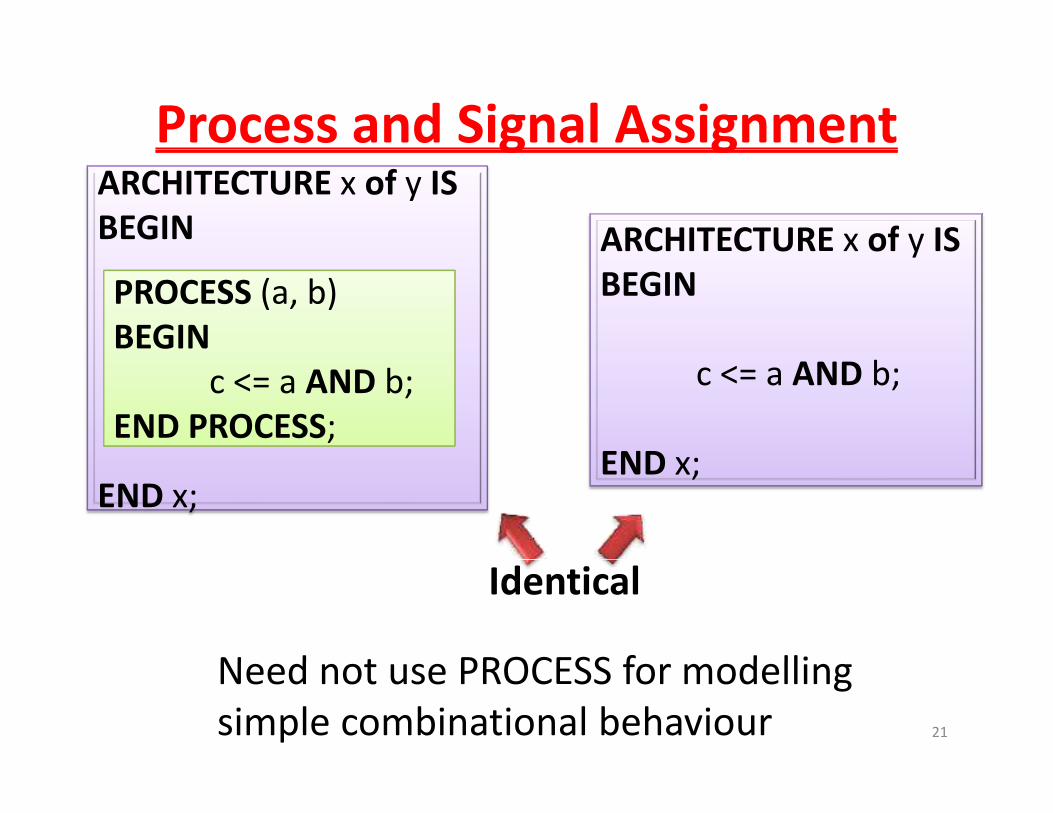
Process and Signal Assignmentg g
ARCHITECTURE x of y IS
ARCHITECTURE x of y ISBEGIN y
BEGINPROCESS (a, b)BEGIN
c <= a AND b;
END
c <= a AND b;
END PROCESS;END x;
END x;
N d t PROCESS f d lli
Identical
21
Need not use PROCESS for modelling
simple combinational behaviour

Process SynchronizationProcess Synchronization• Sensitivity list is optional
• wait is general synchronization mechanism
• Implicit infinite loop in processp p p
• Execution continues until suspended by wait statementstatement
PROCESS
BEGIN
wait on a,b;
PROCESS (a,b) BEGIN
c < a and bc <= a and b;
END PROCESS;
c <= a and b;
END PROCESS;
22Identical
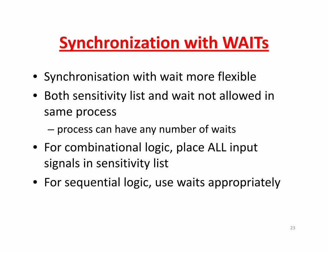
Synchronization with WAITsSynchronization with WAITs
• Synchronisation with wait more flexibleSynchronisation with wait more flexible
• Both sensitivity list and wait not allowed in same processsame process– process can have any number of waits
• For combinational logic, place ALL input signals in sensitivity list
• For sequential logic, use waits appropriately
23
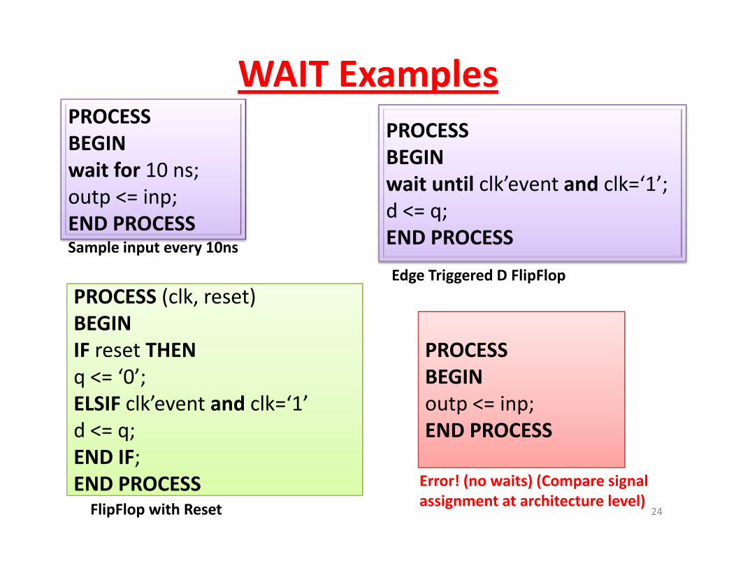
WAIT ExamplesPROCESS
BEGIN
wait for 10 ns;
PROCESS
BEGIN
i il lk’ d lk ‘ ’wait for 10 ns;outp <= inp;END PROCESS
wait until clk’event and clk=‘1’;
d <= q;END PROCESS
Sample input every 10ns
PROCESS (clk, reset)BEGIN
Sample input every 10ns
Edge Triggered D FlipFlop
BEGIN
IF reset THENq <= ‘0’;
PROCESS
BEGIN
ELSIF clk’event and clk=‘1’d <= q;END IF;
outp <= inp;END PROCESS
24
END IF;END PROCESSFlipFlop with Reset
Error! (no waits) (Compare signalassignment at architecture level)

Process VariablesProcess Variables• Variables used for local
icomputations
– within processesPROCESS
VARIABLE result : BIT;BEGIN
• Not associated with events/transactions
BEGIN
wait until clk’event and clk=‘1’;result := ‘0’;
– unlike signals
• Assignment of value is
for i in 0 to 6 loopresult := result XOR inp (i);
end loop;g
immediate
– unlike signals
p;
outp <= result;END PROCESS;
unlike signals
25
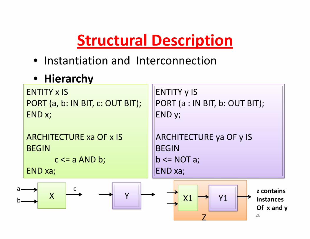
Structural DescriptionStructural Description• Instantiation and Interconnection
h• HierarchyENTITY x IS PORT (a b: IN BIT c: OUT BIT);
ENTITY y ISPORT (a : IN BIT b: OUT BIT);PORT (a, b: IN BIT, c: OUT BIT);
END x;
ARCHITECTURE OF IS
PORT (a : IN BIT, b: OUT BIT);END y;
ARCHITECTURE OF ISARCHITECTURE xa OF x ISBEGIN
c <= a AND b;
ARCHITECTURE ya OF y ISBEGIN
b <= NOT a;END xa; END xa;
Yz contains
Xa c
26
Y
ZZ
X1 Y1 instances Of x and y
Xb

Instantiation and Interconnection ‐ 1Instantiation and Interconnection 1ENTITY z IS
PORT (p, q: IN BIT, r: OUT BIT); END x;END x;
ARCHITECTURE structural OF z ISCOMPONENT xc
ZZ
X1 Y1
COMPONENT xc
PORT (a, b: IN BIT; c: OUT BIT);END COMPONENT;
COMPONENT yc
Component declaration
PORT (a, b: IN BIT; c: OUT BIT);END COMPONENT;
FOR ALL: xc USE WORK.x (xa);Configuration specification(which architecture?)
FOR ALL: yc USE WORK.y (ya);
SIGNAL t: BIT;BEGIN
x1 xc PORT MAP (p q t)
Temporary signal
27
x1: xc PORT MAP (p, q, t);y1: yc PORT MAP (t, r);END structural;
Instantiation
Instantiation and Interconnection ‐ 2Instantiation and Interconnection 2
Xa
b
c
ZZ
X1 Y1
Instance name
Component name
Port association list:
Component name
x1: xc PORT MAP (p, q, t);y1: yc PORT MAP (t, r);
order of names
determines connectivity:a ‐ pa p
b ‐ qc – t
Same name
28
implies connection

Port MappingCOMPONENT xc
PORT (a, b: IN BIT; c: OUT BIT);END COMPONENT;END COMPONENT;
Mapping by position: preferred for short port lists
x1: xc PORT MAP (p, q, t);
x1: xc PORT MAP (b => q, a => p, c => t);
Mapping by name: preferred for long port lists
29
In both cases, complete port mapping should be specified
Test BenchesTest Benches
• Purpose ‐ test correctness of Design UnderPurpose test correctness of Design Under Test (DUT)– provide input stimulus– provide input stimulus
– observe outputs
compare against expected outputs– compare against expected outputs
• Test Bench is also a VHDL model
30
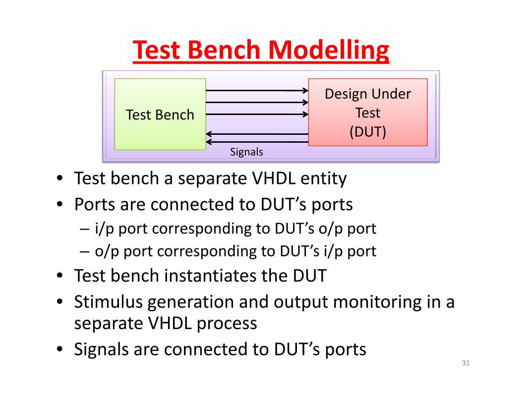
Test Bench Modelling
Test Bench Design Under
Test
• Test bench a separate VHDL entity
(DUT)
Signals
• Test bench a separate VHDL entity• Ports are connected to DUT’s ports
i/p port corresponding to DUT’s o/p port– i/p port corresponding to DUT s o/p port– o/p port corresponding to DUT’s i/p port
• Test bench instantiates the DUTTest bench instantiates the DUT • Stimulus generation and output monitoring in a separate VHDL processseparate VHDL process
• Signals are connected to DUT’s ports31

32