csiro pcc pilot plant activities in australia...1st post combustion capture conference the role of...
TRANSCRIPT

CSIRO PCC Pilot Plant Activities in Australia
Aaron Cottrell19th May 2011 – Abu Dhabi, United Arab Emirates
1st Post Combustion Capture Conference

The role of coal in Australia
Australia is heavily dependant on coal for electricity productionLarge reserves of coal will likely mean future power stations will be coal based
Electricity production ~ 261TWh
Black Coal
Brown Coal
NG
Other
CO2 emissions from electricity production ~ 235 Mt CO2
Black Coal
Brown Coal
NGOther
Abare data : 2008-2009
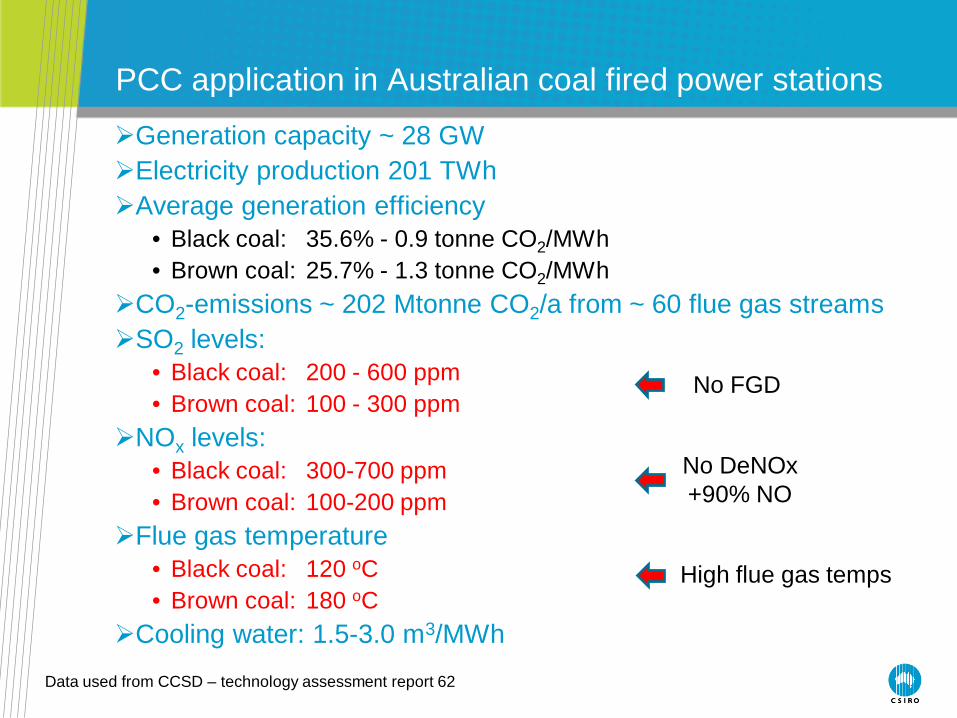
PCC application in Australian coal fired power stations
Generation capacity ~ 28 GWElectricity production 201 TWhAverage generation efficiency
• Black coal: 35.6% - 0.9 tonne CO2/MWh• Brown coal: 25.7% - 1.3 tonne CO2/MWh
CO2-emissions ~ 202 Mtonne CO2/a from ~ 60 flue gas streamsSO2 levels:
• Black coal: 200 - 600 ppm• Brown coal: 100 - 300 ppm
NOx levels:• Black coal: 300-700 ppm• Brown coal: 100-200 ppm
Flue gas temperature• Black coal: 120 oC• Brown coal: 180 oC
Cooling water: 1.5-3.0 m3/MWh
Data used from CCSD – technology assessment report 62
No FGD
No DeNOx+90% NO
High flue gas temps

Opportunities for PCC in Australia
Only practical option for existing plants to substantially reduce CO2intensityPotential for “all in one” multi pollutant control technologyCompared to competing technologies, has high flexibility &
adaptability • staged implementation, zero to full capture operation to match market
conditions• applicable to most stationary sources of CO2 emissions
Special synergies with renewable energy• direct solar integration (provision of low temperature heat for solvent
regeneration avoids reducing output of power station)• grid integration (provides a discretionary load to balance intermittency)
Potential water production sourcePotential waste heat recovery options
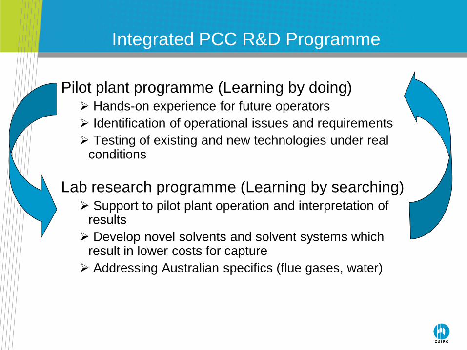
Pilot plant programme (Learning by doing) Hands-on experience for future operators Identification of operational issues and requirements Testing of existing and new technologies under real
conditions
Lab research programme (Learning by searching) Support to pilot plant operation and interpretation of
results Develop novel solvents and solvent systems which
result in lower costs for capture Addressing Australian specifics (flue gases, water)
Integrated PCC R&D Programme

PCC Programme Overview
PCC
Pilot plants Research & Development
Delta Electricity
Loy Yang Power
China Huaneng
Tarong Energy
Novel solventsCET Ionic liquids
CET
Novel processesCET
Economics & IntegrationCET
Solvent synthesisCMHT
AdsorbentsE&M
Environmental impactsCET
EnzymesENT
Learning by doing Learning by searching

Pilot plant summary
Plant Loy Yang Munmorah Tarong Newcastle mini
Solvent Amine Ammonia Amine Both
Flue gas source
brown coal black coal Black coal Artificial
Scale 50 kg/hr 300kg/hr 100kg/hr 20 kg/hr
Focus solvent benchmarking
ammonia operation
process optimisation
process development
Otheractivities
emission study
pressurisedabsorption
Solar thermalintegration
Cutting edge processes
• Pilot work by nature is slow to deliver results• Matrix approach helps cover many aspects of PCC as
well as providing quicker delivery of information• Multiple plants provide extra exposure for power generators

Key gas analysis equipment
Each pilot plant has sophisticated FTIR gas analysis equipment (Gasmet).
Enables online sampling of up to 8 different location on the plant
Currently includes spectra for calculating online concentration of CO2, H2O, CO, NO2, NO, N2O, SO2, HCl, HF, NH3, MEA, PZ and a number of breakdown products
Overall spectra are saved and can be analysed for other “unknown” constituents at a later date.
Highly valuable for measuring plant performance, safety and water balancing

Loy Yang Power Station PCC Pilot PlantVictoria, Australia
ETIS support Lignite
Amine basedNo FGD/DeNox
Operational May 08

Project aims
• Develop experience operating PCC on brown coal flue gas
• Strong focus on solvent testing and benchmarking• Identification of cost-effective options for reduction of
CO2-emissions in Victorian brown coal fired power stations
• Determine effects of CO2-concentration, moisture content, SOx, NOx and fly-ash on sorbent systems and novel separation technologies
• Technical and economical assessment based on results from pilots and laboratory research

Loy Yang Pilot Plant design
Basis of Design:Two absorbers with CO2 capacity up to 50 kg/hr
Each has 2 beds of 1.35 m packed with 5/8” Pall rings – 338 m2/m3, ID 211 mmStripper: 3.9 m bed with Pall rings, ID 161 mmFlue gas composition (11% CO2, 30% H2O)MEA concentration (30%)
Operation Conditions:Reboiler temperatures: 100 – 120 °CStripper pressures: 1 - 2 barFlue gas temperatures: < 180 °C
Objectives:determine Mass & Heat balances for the plantdetermine CO2 recovery and CO2-product qualitydetermine thermal and electrical energy requirements of the pilot plant

Some results from the Loy Yang pilot plant
50
60
70
80
90
100
1.5 2.0 2.5 3.0 3.5 4.0 4.5
L/G (L/Nm³)
CO
2 re
cove
ry (%
)
Liquid analysis CO2 product based treated flue gas based
Artanto et. al. 20094.0
4.5
5.0
5.5
6.0
1.5 2.0 2.5 3.0 3.5 4.0 4.5
L/G (L/Nm³)
Reb
oile
r h
eat
du
ty (
MJ/
kg C
O2)
(75%)
(72%)(60%)
(69%)
(81%)
(83%)
(83%)
(84%)
(90%)
(89%)
Effect of L/G ratio of CO2 recovery
Effect of L/G ratio of Reboiler duty
• First CO2 capture in May 2008
• Able to successfully close mass balances over the plant. Agreement between different methods for determining plant
CO2 recovery
• Effect of various operating conditions of plant
performance observed (e.g. effect of L/G ratio on CO2recovery and reboiler duty
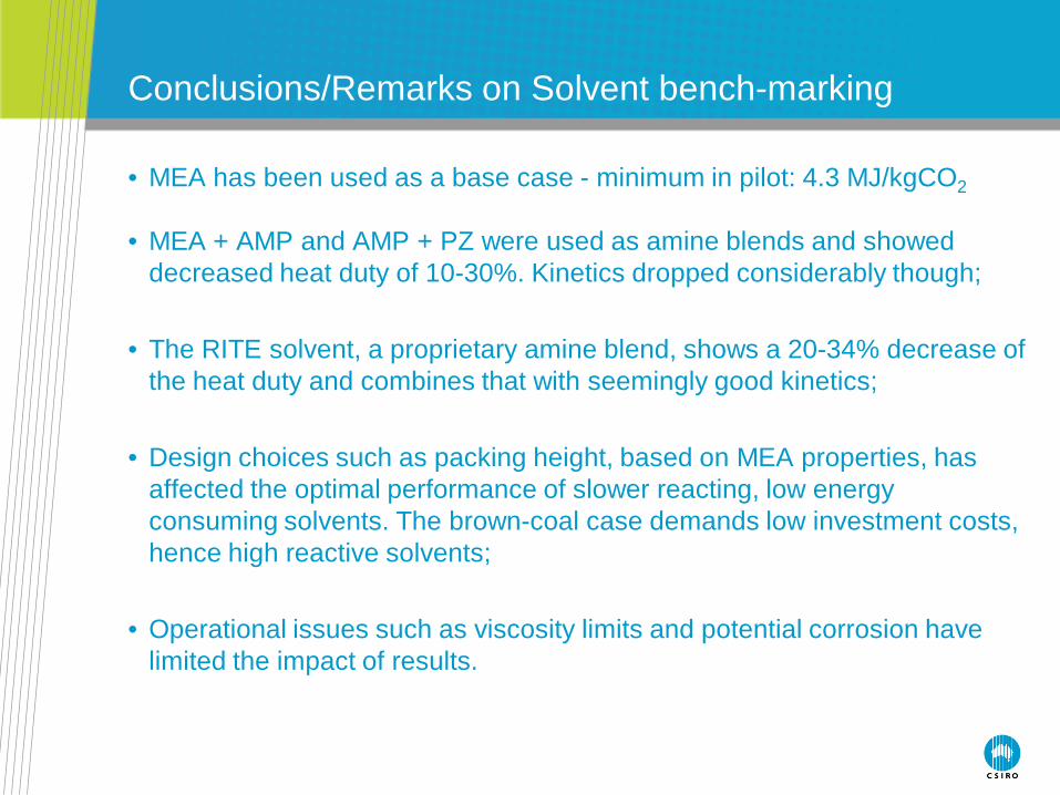
Conclusions/Remarks on Solvent bench-marking
• MEA has been used as a base case - minimum in pilot: 4.3 MJ/kgCO2
• MEA + AMP and AMP + PZ were used as amine blends and showed decreased heat duty of 10-30%. Kinetics dropped considerably though;
• The RITE solvent, a proprietary amine blend, shows a 20-34% decrease of the heat duty and combines that with seemingly good kinetics;
• Design choices such as packing height, based on MEA properties, has affected the optimal performance of slower reacting, low energy consuming solvents. The brown-coal case demands low investment costs, hence high reactive solvents;
• Operational issues such as viscosity limits and potential corrosion have limited the impact of results.

Key learnings from LVPCC project
1. Due to the relatively cheap brown coal supply, cost reductions can be achieved by a focus on reduction of the capital costs and to a lesser extent on the reduction of the energy penalty.
• Solvents with better kinetics• Solvents with lower vapour pressures• Thermally stable solvents• Cheaper materials for plant construction• Simple process design
2. Requirement of FGD and DeNOx may mean PCC for brown coal not feasible. “All in one” technology may have merit.
• Once again capital driven• Less efficient solvent capable of multi pollutant control may be key• Maybe by-products give value

• Original ETIS project has been completed• Ongoing solvent testing and benchmarking• Detailed investigation of PCC emissions
- quantify environmental impact of PCC- determine any associated control technologies are
required• Collaboration with an EU consortium in the iCap project.
- CSIRO will form part of an Australian consortium called coCAPco working with iCap
- aim to develop and test a combined CO2 and SO2 capture process with stepwise regeneration.
Ongoing Research
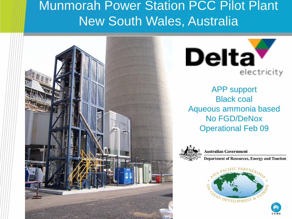
Munmorah Power Station PCC Pilot PlantNew South Wales, Australia
APP support Black coal
Aqueous ammonia basedNo FGD/DeNox
Operational Feb 09

Why ammonia for PCC?
•Ammonia is a relatively cheap liquid absorbent.
•Ammonia is robust and not subject to degradation unlike other amines.
•Multi pollutant control – lower capital costs
•Potential for reduced energy consumption in solvent regeneration
•Potential for more efficient compression via high pressure regeneration pressure
•Potential income stream from ammonium sulfate and ammonium nitrate by-products

Munmorah Pilot Plant design
Basis of Design:Two absorbers with CO2 capacity up to 150 kg/hr
Each has 2 beds of 1-2 m packed with 1” Pall rings – 207 m2/m3, ID 600 mmStripper: 3.5 m bed with Pall rings, ID 400 mmFlue gas composition (11% CO2, 30% H2O)MEA concentration (30%)
Operation Conditions:Reboiler temperatures: 100 – 180 °CStripper pressures: 1 - 10 barFlue gas temperatures: < 120 °C
Objectives:determine Mass & Heat balances for the plantdetermine CO2 recovery and CO2-product qualitydetermine thermal and electrical energy requirements of the pilot plant

Finding the right balanceSmaller absorber (low capital cost), high
operating cost and high solvent lossLarge absorber (high capital cost), lower
operating cost and lower solvent loss

Some results
Measured and equilibrium ammonia concentrations in the flue gas at the outlet of absorber as a function of CO2 loading of lean solvent. Expt: 15-20oC; Model: 15oC.
Ammonia losses in absorber Precipitation of solids in condenser

Key Outcomes of the Munmorah Pilot Plant
Benefits of aqueous ammonia process are confirmed ……. but further challenges also revealed:
• The ammonia losses, as a result of its high volatility, can be substantial (depending on the operating conditions)necessitates the installation of a comprehensive gas washing and
ammonia recovery/neutralisation system.operation at low temperature – refrigeration is expensive to buy
and run • The CO2 absorption rates are low larger absorbers compared to the standard amine processes.effect on investment costs?
• Matching operation to regular amine processesformation of ammonium-bicarbonate solids.blockage of the condenser – significant operational issue
• May still be cost effective multi pollutant process for Australia if we can overcome these challenges with minimal cost

• Original project has been completed• Further trials are set to continue next year after the plant is
relocated to Vales Point Power Station as part of a NSW Clean Coal Proposal
• Plant to be reconfigured to overcome some existing operating issues
• Information gathered to be used in selection/design of demonstration scale PCC plant in NSW
• Trials will include: - pressurised absorption in an attempt to increase
reaction rates, decrease ammonia slip and decrease the effective absorption column size.
- Investigation of other ammonia slip reduction techniques
- Potential of other solvents to be trialled also
Ongoing Research

Tarong Power Station PCC Pilot PlantQueensland, Australia
APP support Black coal
Amine basedNo FGD/DeNox
Commissioned November 2010
Project aims
• To obtain practical experience with real flue gases from a Tarong Energy’s black coal fired power plant
• To test the performance of pilot plant under nominal conditions
• Focus on process reconfigurations with an aim for optimising the CO2 capture process for minimisation of operating and capital costs
• To compare the results with simulation calculations

Tarong pilot plant design
• Pre-Treatment column (flue gas <120°C, 10-12% CO2)• 450mm diameter• 2.7m packed height• 1 inch Pall rings
• Absorber column• 350mm diameter• Total packed height 7.2m (4 sections @ 1.8m each, spare
3.6m packed section)• Wash section packed height 1.6m• Sulzer Mellapak M250X structured packing
• Stripping column (up to 10 bar/180°C operation)• 250mm diameter• Total packed height 7.2m (2 sections @ 3.6m each)• Condensate packed height ~1m• Sulzer Mellapak M350X structured packing
Wash sectionStructured
packing
Bed 1Structured
packing
Demister packing
Bed 2Structured
packing
Bed 3Structured
packing
Bed 4Structured
packing
ABS-TNK1
Condensate bed
Bed 1Structured
packing
Bed 2Structured
packing

Plant campaigns
• Base case determination• Validate pilot plant design with 30 wt% MEA solution.• Determine CO2 recovery performance• Validate liquid sampling system and gas analysis• Achieve stable operation of pilot plant with 30 wt% MEA
solution• Close heat and mass balances
• Rich split modification• Absorber intercooling

Campaign 2 – Rich split case
• The plant was modified to enable an extra stream coming from the bottom of the absorber to be diverted from before the cross heat exchanger to the top of the absorber column.
• The trials measured the change in plant performance by diverting 0-50% of the rich solvent to the top of the stripper column.
• The trial showed that some saving could be made for both energy (up to 8%) and water consumption (up to 85% from the stripper condenser) and this aspect should be investigated further.
• Stripper operation became unstable at higher diversion rates due to increased steam condensation in the column.
• The increased condensation created a flooded region in the column and resulted in surging which caused the instability.

Campaign 3 – Absorber intercooling case
• The absorber was modified to allow liquid to be withdrawn from the column, cooled and then reintroduced to the column at the top of the next section of packing.
• The plant was run with different cooling water flowrates to try and show a trend in plant performance with absorber intercooling.
• Analysis is shows that a small increase in performance can be achieved (2-3%)
• Intercooling performance to be studied further with a modified intercooling circuit.
• From an operating perspective the plant appeared to reach higher rich solvent loadings and in turn reduce energy requirements as a result of these higher loadings.

Heat stable salt measurements
• The plant has run around 800 hours to date on an average flue gas (after treatment) of 5ppm SO2, 180-200ppm NO, ~1ppm NO2
• Solvent not showing any noticeable decrease in performance
0
0.05
0.1
0.15
0.2
0.25
0.3
0.35
0.4
0 100 200 300 400 500 600
Hours of operation
Hea
t st
able
sal
t co
nce
ntr
atio
n (
wt%
)
Solvent discolouration also observed– still to be investigated

Online Gas Analysis

Corrosion testing
• Determine the corrosiveness of solvents for the different operating conditions within the plant
• Corrosion testing is be conducted at various locations around the plant.
• Access points have been included on both the absorber and stripping columns to allow placement of corrosion coupon test racks.
• Different metals will be tested from mild steel to 316 stainless steel
• Also examine the effects of corrosion of welds• All information collected assists in design and
material selection of up coming plants and requirements for different
• Corrosion studies are yet to be completed.

Current Status and future work
• Unmanned 24hr operation tests complete. More solvent operation hours with no additional staff.
• Preparing for tests on concentrated Piperazine in collaboration with University of Texas, DOE, URS and Trimeric
• Upgraded cross heat exchanger to minimise approach temperatures
• Upgraded intercooling circuit for more efficient cooling• In a couple of months tests on concentrated Piperazine
in collaboration with University of Texas, DOE, URS and Trimeric utilising 2 stage flash skid.
• Solar thermal integration for regeneration• Other process configurations

Novel process development unit
• Located at Newcastle Energy Technology
Labs
• Scale between Lab bench scale and Pilot
scale
• Modular design
• Flexible operation
• Ventilated & bundedspace
• “Controlled” environment

PCC Novel Processes Test Facility- contactors
• Detailed profiles in multi-stage systems
• Separate operation of Absorber and Desorber
• Process and contactor options
• Currently being commissioned

Learnings to Date from Ongoing Programme
• Liquid absorbent based PCC is a viable option for Australia.
• Significant operating and capital costs reductions can be achieved in solvent selection, process configuration
• Ammonia has potential to provide a multi pollutant control solution but operating difficulties and solvent losses need to be further addressed.
• The flue gas quality of Australian power plants is such that FGD and possibly De-NOX may need to be installed to enable the current commercially available PCC processes to be successful in Australia
• The Environmental impacts resulting from PCC processes are not well understood and need further investigation.

What’s Next?
• Work closely with power industry and address their concerns• Scaled up demonstration projects are needed to show that
CCS technologies work.• Further study into the environmental impacts of large scale
CCS
• Development of novel solvent processes to reduce capital costs and loss in efficiency
• Further understanding of the PCC and renewable energy relationship for Australian conditions – opportunities for load balancing and energy reduction

View of Tarong pilot plant

Contact UsPhone: 1300 363 400 or +61 3 9545 2176
Email: [email protected] Web: www.csiro.au
Thank you
CSIRO Energy TechnologyAaron Cottrell
PCC Pilot Plant Project ManagerPost-combustion CO2 CapturePhone: +61 (0)2 4960 6053
Email: [email protected]: www.csiro.au