csm e3z ds e 13 1 - wordpress.com · 2011-10-23 · csm_e3z_ds_e_13_1 compact photoelectric sensor...
TRANSCRIPT

1
CSM_E3Z_DS_E_13_1
Compact Photoelectric Sensor with Built-in Amplifier
E3ZThe Standard for Photoelectric Sensors with a Secure Track Record of One Million Sold Yearly. • Long sensing distance of 30 m for Through-beam Models, 4 m for
Retro-reflective Models, and 1 m for Diffuse-reflective Models. • Mechanical axis and optical axis offset of less than ±2.5° simplifies
optical axis adjustment.
• High stability with unique algorithm that prevents interference of external light.
Be sure to read Safety Precautions on page 15.
Features
Industry's Top-level Sensing Distance with Built-in AmplifierA separately sold filter is available to prevent mutual interference for Through-beam Models with red lights sources and a sensing distance of 10 m. Reflective Models include functionality to prevent mutual interference.
Long-distance, Through-beam Sensors with a detection distance of 30 m (response time: 2 ms) are also available.
Low-temperature Operation for Applications in Cold-storage WarehousesA wider ambient operating range from −40 to 55°C (main models with connectors). We also provide Sensor I/O Connectors with PUR Cables for high resistance to cold environments.
Improved Matching of Optical Axis and Mechanical Axis for Through-beam Models and Retro-reflective ModelsThe offset between the optical axis and the mechanical axis is kept within ±2.5°, so the optical axis can be accurately set simply by mounting the Sensor according to the mechanical axis.
Sensor Protection against Incorrect Wiring The Sensor includes output reverse polarity protection. (A diode to protect against reverse polarity is added to the output line.)
Complete Compliance with the EU's RoHS DirectiveLead, mercury, cadmium hexachrome, polybrominated biphenyl (PBB), and polybrominated diphenyl ether (PBDE) have all been eliminated. Also, burnable polyethylene packaging has been used.
Through-beam
Retro-reflective with MSR function
30 m
Diffuse-reflective
1 m
4 m Distance-settable
20 cm
30 m
Optical axis
2.5° max. mechanicalaxis
The receiver will always be in the range of light diffusion.
Through-beam Model receivers and Reflective Models (except the E3Z-LS)
Protection for NPN output models
4
3
112 to 24 VDCBrown
Black
Blue
100 mAmax.
Operation indicator(orange)
Stabilityindicator(green)
0 V
ZD
Load(relay)
Photo-electric Sensormaincircuit
ecoPb

2
E3ZOrdering Information
Sensors [Refer to Dimensions on page 16.]
*1. The Reflector is sold separately. Select the Reflector model most suited to the application.*2. The sensing distance specified is possible when the E39-R1S is used. Values in parentheses indicate the minimum required distance between the Sensor and Reflector.*3. Through-beam Sensors are normally sold in sets that include both the Emitter and Receiver.
Orders for individual Emitters and Receivers are accepted. (Modifications are required for some models. Ask your OMRON representative for details.)*4. Models with emission stop function. Refer to page 8, Photoelectric Sensors Technical Guide for details.
Sensing method Appearance Connection method Sensing distanceModel
NPN output PNP output
Through-beam(Emitter + Receiver) *3
Pre-wired (2 m)E3Z-T61 2M E3Z-T81 2MEmitter E3Z-T61-L 2MReceiver E3Z-T61-D 2M
Emitter E3Z-T81-L 2MReceiver E3Z-T81-D 2M
Standard M8 connectorE3Z-T66 E3Z-T86Emitter E3Z-T66-LReceiver E3Z-T66-D
Emitter E3Z-T86-LReceiver E3Z-T86-D
Pre-wired (2 m)E3Z-T61A 2M E3Z-T81A 2MEmitter E3Z-T61-A-L 2MReceiver E3Z-T61-A-D 2M
Emitter E3Z-T81-A-L 2MReceiver E3Z-T81-A-D 2M
Standard M8 connectorE3Z-T66A E3Z-T86AEmitter E3Z-T66-A-LReceiver E3Z-T66-A-D
Emitter E3Z-T86-A-LReceiver E3Z-T86-A-D
Pre-wired (2 m)E3Z-T62 2M E3Z-T82 2MEmitter E3Z-T62-L 2MReceiver E3Z-T62-D 2M
Emitter E3Z-T82-L 2MReceiver E3Z-T82-D 2M
Standard M8 connectorE3Z-T67 E3Z-T87Emitter E3Z-T67-LReceiver E3Z-T67-D
Emitter E3Z-T87-LReceiver E3Z-T87-D
Emission stop function
Pre-wired (2 m) E3Z-T62-G0 2M *4 E3Z-T82-G0 2M *4Emitter E3Z-T62-G0-L 2MReceiver E3Z-T62-G0-D 2M
Emitter E3Z-T82-G0-L 2MReceiver E3Z-T82-G0-D 2M
Standard M8 connectorE3Z-T67-G0 *4 E3Z-T87-G0 *4Emitter E3Z-T67-G0-LReceiver E3Z-T67-G0-D
Emitter E3Z-T87-G0-LReceiver E3Z-T87-G0-D
Retro-reflective with MSR function *1
Pre-wired (2 m) E3Z-R61 2M E3Z-R81 2M
Standard M8 connector E3Z-R66 E3Z-R86
Diffuse-reflective
Pre-wired (2 m) E3Z-D61 2M E3Z-D81 2M
Standard M8 connector E3Z-D66 E3Z-D86
Pre-wired (2 m) E3Z-D62 2M E3Z-D82 2M
Standard M8 connector E3Z-D67 E3Z-D87
Pre-wired (2 m) E3Z-L61 2M E3Z-L81 2M
Standard M8 connector E3Z-L66 E3Z-L86
Distance-settableRefer to E3Z-LS.
Pre-wired (2 m) E3Z-LS61 2M E3Z-LS81 2M
Standard M8 Connector E3Z-LS66 E3Z-LS86
Pre-wired (2 m) E3Z-LS63 2M E3Z-LS83 2M
Standard M8 connector E3Z-LS68 E3Z-LS88
Slit-type Through-beamRefer to E3Z-G.
1 axisPre-wired (2 m)
E3Z-G61 2M E3Z-G81 2M
2 axes E3Z-G62 2M E3Z-G82 2M
1 axisPre-wired M8 connector
E3Z-G61-M3J E3Z-G81-M3J
2 axes E3Z-G62-M3J E3Z-G82-M3J
Limited-reflective for transparent glasses
Pre-wired (2 m) E3Z-L63 2M E3Z-L83 2M
Standard M8 connector E3Z-L68 E3Z-J88
Retro-reflective with-out MSR function for clear, plastic bottles
Pre-wired (2 m) *2 E3Z-B61 2M E3Z-B81 2M
Standard M8 connector E3Z-B66 E3Z-B86
Pre-wired (2 m) *2 E3Z-B62 2M E3Z-B82 2M
Standard M8 connector E3Z-B67 E3Z-B87
Red light Infrared light
15 m
10 m
30m
4 m (100 mm)
*2
5 to 100 mm(wide view)
1 m
90±30 mm (narrow beam)
20 to 40 mm (BGS min setting)20 to 200 mm (BGS max setting)
40 min. Incident threshold (FGS min setting)
200 min. Incident threshold (FGS max setting)
2 to 20 mm (BGS min setting)2 to 80 mm (BGS max setting)
25 mm
30±20 mm
*1
500 mm (80 mm)
2 m (500 mm)

3
E3Z
Variety of Connection Specifications The models with the connection specifications marked with a black circle in the table are available. The model number indication is a combination of the basic model and the connection specification.
NPN Output
Clamp-type e-CON pre-wired connectors are also available for models shaded in . Add "-ECON-C 2M" after the basic model number to specify the connectors.
Example: E3Z-T61-M1TJ 0.3M
Basic modelnumber
Connectionspecification
ModelModel
number example
E3Z-T61-M1TJ 0.3M E3Z-T61 0.5M E3Z-T61 5M E3Z-T61
-M1J 0.3ME3Z-T61
-M3J 0.3M
E3Z-T61-ECON 0.3M
E3Z-T61-ECON 0.5M
E3Z-T61-ECON 2M
Sensing method
Sens-ing dis-tance
Main features
Connec-tion
specifi-cation
M12 pre-wired Smart-click connec-
tor (cable length: 0.3 m)
Pre-wired (cable length:
0.5 m)
Pre-wired (cable length:
5 m)
M12 pre-wired stan-
dard connec-tor (cable
length: 0.3 m)
M8, 4-pin pre-wired con-
nector (cable length: 0.3 m)
e-CON pre-wired con-
nector (cable length: 0.3 m/
0.5 m)
e-CON pre-wired con-
nector (cable length: 2 m)
Basic model number
-M1TJ 0.3M 0.5M 5M -M1J 0.3M -M3J 0.3M-ECON 0.3M
-ECON 0.5M-ECON 2M
Through-beam
15 m Infrared light E3Z-T61
10 m Redlight E3Z-T61A --- ---
30 m 2-ms re-sponse E3Z-T62 --- --- --- --- --- ---
Retro-reflective 4 m MSR
function E3Z-R61
Diffuse-reflective (narrow-beam re-flective)
100 mm Wide view E3Z-D61 ---
1 mLong dis-tance
E3Z-D62
90 mm Narrow beam E3Z-L61 ---
Distance-settable
200 mm FGS function E3Z-LS61 ---
80 mm Small spot E3Z-LS63 --- --- --- --- --- ---
Slit-type 25 mm
1 optical axis E3Z-G61
2 optical axes E3Z-G62 ---
Retro-reflective for clear, plastic bottles
500 mm
No MSR function
E3Z-B61 --- --- ---
2 m E3Z-B62 --- ---

4
E3Z
PNP Output
ModelModel
number example
E3Z-T81-M1TJ 0.3M E3Z-T81 0.5M E3Z-T81 5M E3Z-T81
-M1J 0.3ME3Z-T81
-M3J 0.3M
Sensing method
Sens-ing dis-tance
Main features
Connec-tion
specifi-cation
M12 pre-wired Smartclick connector
(cable length: 0.3 m)
Pre-wired (cable length:
0.5 m)
Pre-wired (cable length:
5 m)
M12 pre-wired standard con-nector (cable length: 0.3 m)
M8, 4-pin pre-wired connec-
tor (cable length: 0.3 m)
Basic model number
-M1TJ 0.3M 0.5M 5M -M1J 0.3M -M3J 0.3M
Through-beam
15 m Infrared light E3Z-T81
10 m Red light E3Z-T81A --- --- --- ---
30 m 2-ms re-sponse E3Z-T82 --- --- --- ---
Retro-reflective 4 m MSR
function E3Z-R81
Diffuse-reflective (narrow-beam reflective)
100 mm Wideview E3Z-D81
1 mLong dis-tance
E3Z-D82
90 mm Narrow beam E3Z-L81 ---
Distance-settable
200 mm FGS function E3Z-LS81 ---
80 mm Small spot E3Z-LS83 --- --- --- ---
Slit-type 25 mm
1 optical axis E3Z-G81 ---
2 optical axes E3Z-G82 --- ---
Retro-reflective for clear, plastic bottles
500 mm
No MSR function
E3Z-B81 --- --- ---
2 m E3Z-B82 --- ---

5
E3Z
Oil-resistive Sensors [Refer to Dimensions on page 16.]
*1. The Reflector is sold separately. Select the Reflector model most suited to the application. *2. The sensing distance specified is possible when the E39-R1S is used. Values in parentheses indicate the minimum required distance between the Sensor and Reflector. *3. Through-beam Sensors are normally sold in sets that include both the Emitter and Receiver.
Orders for individual Emitters and Receivers are accepted. (Modifications are required for some models. Ask your OMRON representative for details.)
Accessories (Order Separately)Slit (A Slit is not provided with Through-beam Sensors) Order a Slit separately if required. [Refer to Dimensions on page 18.]
Reflectors (Reflector required for Retroreflective Sensors) A Reflector is not provided with the Sensor. Be sure to order a Reflector separately.[Refer to Dimensions on E39-L/F39-L/E39-S/E39-R]
Note: The actual sensing distance may be reduced to approximately 70% of the typical sensing distance when using a Reflector other than E39-R1 or E39-R1S.*1. Refer to Reflectors on E39-L/F39-L/E39-S/E39-R for details.*2. Values in parentheses indicates the minimum required distance between the Sensor and Reflector.
Mutual Interference Protection Filter A Filter is not provided with the Sensor (for the through-beam E3Z-T@@A). Order a Filter separately if required.
Sensing method Appearance Connection meth-od Sensing distance
ModelNPN output PNP output
Through-beam(Emitter + Receiver) *3
Pre-wired (2 m)E3Z-T61K 2M E3Z-T81K 2MEmitter E3Z-T61K-L 2MReceiver E3Z-T61K-D 2M
Emitter E3Z-T81K-L 2MReceiver E3Z-T81K-D 2M
Pre-wired M8 connectorE3Z-T61K-M3J 0.3M E3Z-T81K-M3J 0.3MEmitter E3Z-T61K-L-M3J 2MReceiver E3Z-T61K-D-M3J 2M
Emitter E3Z-T81K-L-M3J 2MReceiver E3Z-T81K-D-M3J 2M
Retro-reflective with MSR function *1
Pre-wired (2 m) *2 E3Z-R61K 2M E3Z-R81K 2M
Pre-wired M8 connector E3Z-R61K-M3J 0.3M E3Z-R81K-M3J 0.3M
Diffuse-reflective
Pre-wired (2 m) E3Z-D61K 2M E3Z-D81K 2M
Pre-wired M8 connector E3Z-D61K-M3J 0.3M E3Z-D81K-M3J 0.3M
Pre-wired (2 m) E3Z-D62K 2M E3Z-D82K 2M
Pre-wired M8 connector E3Z-D62K-M3J 0.3M E3Z-D82K-M3J 0.3M
Slit widthSensing distance Minimum detectable object
(typical) Model ContentsE3Z-T@@ E3Z-T@@A
0.5-mm dia. 50 mm 35 mm 0.2-mm dia. E39-S65A
One set (contains Slits for
both the Emitter and Receiver)
1-mm dia. 200 mm 150 mm 0.4-mm dia. E39-S65B2-mm dia. 800 mm 550 mm 0.7-mm dia. E39-S65C
0.5 × 10 mm 1 m 700 mm 0.2-mm dia. E39-S65D1 × 10 mm 2.2 m 1.5 m 0.5-mm dia. E39-S65E2 × 10 mm 5 m 3.5 m 0.8-mm dia. E39-S65F
Red light Infrared light
15 m
3 m (150 mm)
5 to 100 mm (wide view)
1 m
NameSensing distance (typical)*
Model Quantity RemarksE3Z-R E3Z-R@K E3Z-B@1/-B@6 E3Z-B@2/-B@7
Reflector
3 m (100 mm) (rated value)
2 m (100 mm) (rated value)
--- --- E39-R1 1
• Retro-reflective models are not provided with Reflectors.
• The MSR function is enabled.
4 m (100 mm) (rated value)
3 m (150 mm) (rated value)
500 mm (80 mm) (rated value)
2 m (500 mm) (rated value) E39-R1S 1
5 m (100 mm) --- --- --- E39-R2 12.5 m (100 mm) --- --- --- E39-R9 13.5 m (100 mm) --- --- --- E39-R10 1
Fog Preventive Coating 3 m (100 mm) ---
500 mm (80 mm) (rated value)
2 m (500 mm) (rated value) E39-R1K 1
Small Reflector 1.5 m (50 mm) --- --- --- E39-R3 1
Tape Reflector700 mm (150 mm) --- --- --- E39-RS1 11.1 m (150 mm) --- --- --- E39-RS2 11.4 m (150 mm) --- --- --- E39-RS3 1
Sensing distance Appearance/Dimensions Model Quantity Remarks
3 m E39-E11Two sets each for the Emitter and Receiver(total of four pieces)
Can be used with the E3Z-T@@A Through-beam models. The arrow indicates the direc-tion of polarized light. Mutual interference can be prevented by altering the direction of polarized light from or to adjacent Emitters and Receivers.0.2
1
4.910.87.4
11.231.4

6
E3Z
Mounting Brackets A Mounting Bracket is not enclosed with the Sensor. Order a Mounting Bracket separately if required. [Refer to Dimensions on E39-L/F39-L/E39-S/E39-R]
Note: 1. When using Through-beam models, order one bracket for the Receiver and one for the Emitter.2. Refer to Mounting Brackets on E39-L/F39-L/E39-S/E39-R for details.
* Cannot be used for Standard Connector models.
Sensor I/O Connectors (Models for Connectors and Pre-wired Connectors: A Connector is not provided with the Sensor. Be sure to order a Connector separately.)[Refer to Dimensions for XS3, XS2, XS5. For e-CON, inquire.]
Note: When using Through-beam models, order one connector for the Receiver and one for the Emitter.*1. Refer to Introduction to Sensor I/O Connectors for details.*2. The Sensor can be used in low-temperature environments (−25°C to −40°C). Do not use the Sensor in locations that are subject to oil.*3. The connector will not rotate after connecting.*4. The cable is fixed at an angle of 180° from the sensor emitter/receiver surface.
Appearance Model (material) Quantity Remarks Appearance Model (material) Quantity Remarks
E39-L153(SUS304)
1
Mounting Brackets
E39-L98(SUS304)
1 Metal Protective Cover Bracket *
E39-L104(SUS304)
1E39-L150(SUS304)
1 set
(Sensor adjuster)
Easily mounted to the aluminum frame rails of conveyors and easily adjusted.
For left to right adjust-ment
E39-L43(SUS304)
1 Horizontal Mounting Brackets *
E39-L151(SUS304)
1 set
E39-L142(SUS304)
1 Horizontal Protective Cover Bracket *
E39-L44(SUS304)
1 Rear Mounting Bracket E39-L144(SUS304)
1Compact Protective Cover Bracket (For E3Z only) *
Size Cable Appearance Cable type Model
M8 *1
Standard
2 m
4-wire
XS3F-M421-402-A
5 m XS3F-M421-405-A
2 m XS3F-M422-402-A
5 m XS3F-M422-405-A
M12 *1(For -M1J models)
2 m
3-wire
XS2F-D421-DC0-A
5 m XS2F-D421-GC0-A
2 m XS2F-D422-DC0-A
5 m XS2F-D422-GC0-A
M12(For -M1TJ models)
2 m4-wire
XS5F-D421-D80-A
5 m XS5F-D421-G80-A
e-CON
2 m
4-wire
E39-ECON2M
5 m E39-ECON5M
0.5 to 1 m E39-ECONW@M@ indicates cable length (in units of m). Specify with 0.1-increments.
1.1 to 1.5 m
1.6 to 2 m
M8PUR(Polyure-thane) cable *2
2 m
4-wire
XS3F-M421-402-L
5 m XS3F-M421-405-L
2 m XS3F-M422-402-L
5 m XS3F-M422-405-L
Straight *3
L-shaped *3 *4
Straight *3
L-shaped *3
Straight
12
34
Single-end connector
12
34
43
12
Double-end connectors
Straight *3
L-shaped *3 *4
7
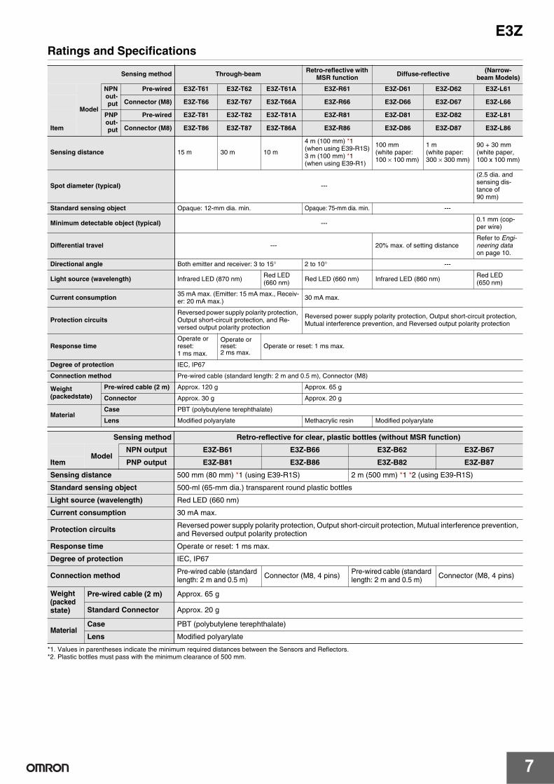
E3ZRatings and Specifications
*1. Values in parentheses indicate the minimum required distances between the Sensors and Reflectors.*2. Plastic bottles must pass with the minimum clearance of 500 mm.
Sensing method Through-beam Retro-reflective with MSR function Diffuse-reflective (Narrow-
beam Models)
Model
NPNout-put
Pre-wired E3Z-T61 E3Z-T62 E3Z-T61A E3Z-R61 E3Z-D61 E3Z-D62 E3Z-L61
Connector (M8) E3Z-T66 E3Z-T67 E3Z-T66A E3Z-R66 E3Z-D66 E3Z-D67 E3Z-L66
PNPout-put
Pre-wired E3Z-T81 E3Z-T82 E3Z-T81A E3Z-R81 E3Z-D81 E3Z-D82 E3Z-L81
Item Connector (M8) E3Z-T86 E3Z-T87 E3Z-T86A E3Z-R86 E3Z-D86 E3Z-D87 E3Z-L86
Sensing distance 15 m 30 m 10 m
4 m (100 mm) *1(when using E39-R1S)3 m (100 mm) *1(when using E39-R1)
100 mm (white paper: 100 × 100 mm)
1 m (white paper: 300 × 300 mm)
90 + 30 mm (white paper, 100 x 100 mm)
Spot diameter (typical) ---
(2.5 dia. and sensing dis-tance of 90 mm)
Standard sensing object Opaque: 12-mm dia. min. Opaque: 75-mm dia. min. ---
Minimum detectable object (typical) --- 0.1 mm (cop-per wire)
Differential travel --- 20% max. of setting distanceRefer to Engi-neering dataon page 10.
Directional angle Both emitter and receiver: 3 to 15° 2 to 10° ---
Light source (wavelength) Infrared LED (870 nm) Red LED(660 nm) Red LED (660 nm) Infrared LED (860 nm) Red LED
(650 nm)
Current consumption 35 mA max. (Emitter: 15 mA max., Receiv-er: 20 mA max.) 30 mA max.
Protection circuitsReversed power supply polarity protection, Output short-circuit protection, and Re-versed output polarity protection
Reversed power supply polarity protection, Output short-circuit protection, Mutual interference prevention, and Reversed output polarity protection
Response timeOperate or reset: 1 ms max.
Operate or reset: 2 ms max.
Operate or reset: 1 ms max.
Degree of protection IEC, IP67
Connection method Pre-wired cable (standard length: 2 m and 0.5 m), Connector (M8)
Weight(packedstate)
Pre-wired cable (2 m) Approx. 120 g Approx. 65 g
Connector Approx. 30 g Approx. 20 g
MaterialCase PBT (polybutylene terephthalate)
Lens Modified polyarylate Methacrylic resin Modified polyarylate
Sensing method Retro-reflective for clear, plastic bottles (without MSR function)
ModelNPN output E3Z-B61 E3Z-B66 E3Z-B62 E3Z-B67
Item PNP output E3Z-B81 E3Z-B86 E3Z-B82 E3Z-B87
Sensing distance 500 mm (80 mm) *1 (using E39-R1S) 2 m (500 mm) *1 *2 (using E39-R1S)
Standard sensing object 500-ml (65-mm dia.) transparent round plastic bottles
Light source (wavelength) Red LED (660 nm)
Current consumption 30 mA max.
Protection circuits Reversed power supply polarity protection, Output short-circuit protection, Mutual interference prevention, and Reversed output polarity protection
Response time Operate or reset: 1 ms max.
Degree of protection IEC, IP67
Connection method Pre-wired cable (standard length: 2 m and 0.5 m) Connector (M8, 4 pins) Pre-wired cable (standard
length: 2 m and 0.5 m) Connector (M8, 4 pins)
Weight (packedstate)
Pre-wired cable (2 m) Approx. 65 g
Standard Connector Approx. 20 g
MaterialCase PBT (polybutylene terephthalate)
Lens Modified polyarylate

8
E3Z
The E3Z-T@2-G0 is equipped with an emission stop function. Ratings and specifications of this function are given in the following table.
Visible spot models are available for through-beam NPN output models. The different items from E3Z-T62 are listed below.
Item Sensing methodOutput and Modes Through-beam models, NPN output: E3Z-T62/T67-G0, PNP output: E3Z-T82/T87-G0
Emission stop function
Input
<NPN models> Emission OFF: Short-circuit to 0 V or 1.5 V max. (Outflow current 1 mA max.), Emission ON: Discon-nected (Leakage current 0.1 mA max.)<PNP models> Emission OFF: Short-circuit to +DC (Power supply plus side) or +DC-1.5 V max. (Inlet current 3 mA max.), Emission ON: Disconnected (Leakage current 0.1 mA max.)
Response time Operate or reset: 0.5 ms max.
Model E3Z-T62-SOSDW-P2
Light source (wavelength) Orange LED (615 nm)
Response time Operate or reset: 1 ms max.
Connection method Pre-wired lable (Standard length: 2 m)
Sensing method Transparent glass Limited-reflective (for transparent object detection )
Model NPN output E3Z-L63 E3Z-L68
Item PNP output E3Z-L83 E3Z-L88
Sensing distance 30±20 mm (transparent glasses 100 × 100 mm)
Spot diameter 2-mm dia. min. (at sensing distance of 30 mm)
Minimum detectable object (typical) 0.1 mm dia. (copper wire)
Light source (wavelength) Red LED (660 nm)
Current consumption 30 mA max.
Protection circuits Power supply reverse polarity protection, Output short-circuit protection, Mutual interference prevention,Reverse output polarity protection
Response time Operate or reset: 1 ms max.
Degree of protection IEC, IP67
Connection method Pre-wired (standard length: 2 m) M8 connector
Weight (packed state)
Pre-wired cable (2 m) Approx. 65 g
Standard Connector Approx. 20 g
MaterialCase PBT (polybutylene terephthalate)
Lens Modified polyarylate

9
E3Z
Oil-resistant
* Values in parentheses indicate the minimum required distance between the Sensor and Reflector.
Common
* The ambient temperature range during operation for connector models depends on the model. For the E3Z-T66/T86/R66/R86, the range is −40°C to 55°C. For the E3Z-D66/D86/D67/D87, the range is −30°C to 55°C. For other connector models, the range is −25°C to −55°C.The sensing distance for Retro-reflective Models (E3Z-R66/R86) between −40°C to −25°C, however, will be as follows (not the values in the table): With E39-R1S: 3 m (100 mm), With E39-R1: 2 m (100 mm). Also, use the XS3F-M42@-4@@-L Sensor I/O Connector (PUR cable) for applications between −25°C to −40°C. (Refer to page 6.)
Sensing method Through-beam Retro-reflective Diffuse-reflective
Model
NPNout-put
Pre-wired Models E3Z-T61K E3Z-R61K E3Z-D61K E3Z-D62K
M8 Pre-wired connector E3Z-T61K-M3J E3Z-R61K-M3J E3Z-D61K-M3J E3Z-D62K-M3J
PNPout-put
Pre-wired Models E3Z-T81K E3Z-R81K E3Z-D81K E3Z-D82K
Item M8 Pre-wired connector E3Z-T81K-M3J E3Z-R81K-M3J E3Z-D81K-M3J E3Z-D82K-M3J
Sensing distance 15 m
3 m (150 mm) *(when using E39-R1S)2 m (100 mm) *(when using E39-R1)
100 mm (white paper: 100 ×100 mm)
1 m (white paper: 300 ×300 mm)
Standard sensing object Opaque: 12-mm dia. min. Opaque: 75-mm dia. min. ---
Differential travel --- 20% max. of setting distance
Directional angle Both emitter and receiver: 3 to 15° 2 to 10° ---
Light source (wavelength) Infrared LED (870 nm) Red LED (660 nm) Infrared LED (860 nm)
Current consumption35 mA max. (Emitter: 15 mA max., Receiver: 20 mA max.)
30 mA max.
Protection circuits
Reversed power supply polarity protection, Output short-circuit protection, and Reversed output po-larity protection
Reversed power supply polarity protection, Output short-circuit protection, Mutual in-terference prevention, and Reversed output polarity protection
Response time Operate or reset: 1 ms max.
Degree of protection IP67 (IEC), Oil resistant models: IP67 (IEC) (in-house standards: oilproof), excluding cables and connectors
Connection method Pre-wired cable (standard length: 2 m), M8 Pre-wired Connector
Weight(packedstate)
Pre-wired cable (2 m) Approx. 120 g Approx. 65 g
Connector (M8, 4 pins) Approx. 50 g Approx. 30 g
MaterialCase PBT (polybutylene terephthalate)
Lens Modified polyarylate Methacrylic resin Modified polyarylate
Power supply voltage 12 to 24 VDC±10%, ripple (p-p): 10% max.
Control output
Load power supply voltage: 26.4 VDC max., Load current: 100 mA max.Residual voltage: Load current of less than 10 mA: 1 V max.
Load current of 10 to 100 mA: 2 V max.Open collector output (NPN/PNP depending on model)Light-ON/Dark-ON selectable
Sensitivity adjustment One-turn adjuster
Ambient illumination (Receiver side) Incandescent lamp: 3,000 lx max.Sunlight: 10,000 lx max.
Ambient temperature range Operating: −25 to 55°C, Some connector models: −40°C to 55°C * (with no icing or condensation)Storage: −40 to 70°C (with no icing or condensation)
Ambient humidity range Operating: 35% to 85%, Storage: 35% to 95% (with no condensation)
Insulation resistance 20 MΩ min. at 500 VDC
Dielectric strength 1,000 VAC, 50/60 Hz for 1 min
Vibration resistance Destruction: 10 to 55 Hz, 1.5 mm double amplitude for 2 hours each in X, Y, and Z directions
Shock resistance Destruction: 500 m/s2 3 times each in X, Y, and Z directions
IndicatorOperation indicator (orange)Stability indicator (green)Through-beam Emitter has power indicator (orange) only.
Accessories Instruction manual (Neither Reflectors nor Mounting Brackets are provided with any of the above models.)
10
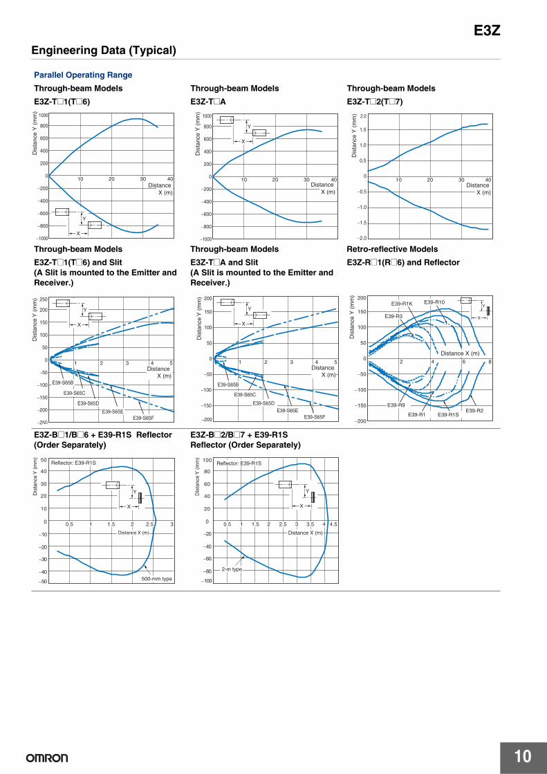
E3ZEngineering Data (Typical)
Parallel Operating Range
Through-beam Models Through-beam Models Through-beam Models
E3Z-T@1(T@6) E3Z-T@A E3Z-T@2(T@7)
Through-beam Models Through-beam Models Retro-reflective Models
E3Z-T@1(T@6) and Slit(A Slit is mounted to the Emitter and Receiver.)
E3Z-T@A and Slit(A Slit is mounted to the Emitter and Receiver.)
E3Z-R@1(R@6) and Reflector
E3Z-B@1/B@6 + E39-R1S Reflector (Order Separately)
E3Z-B@2/B@7 + E39-R1SReflector (Order Separately)
1000
800
600
400
200
0
−200
−400
−600
−800
−1000
40302010Distance
X (m)
Y
X
Dis
tanc
e Y
(m
m)
1000
800
600
400
200
0
−200
−400
−600
−800
−1000
40302010
Y
X
DistanceX (m)
Dis
tanc
e Y
(m
m)
2.0
1.5
1.0
0.5
0
−0.5
−1.0
−1.5
−2.0
40302010Distance
X (m)
Dis
tanc
e Y
(m
m)
Y
X
250
200
150
100
50
0
−50
−100
−150
−200
−250
54321
E39-S65B
E39-S65C
E39-S65D
E39-S65EE39-S65F
DistanceX (m)
Dis
tanc
e Y
(m
m) 200
150
100
50
0
−50
−200
−150
−100
54321
E39-S65B
E39-S65C
E39-S65DE39-S65E
E39-S65F
DistanceX (m)
Dis
tanc
e Y
(m
m)
Y
X
Y
X
200
150
100
50
0
−50
−100
−150
−200
8642
E39-R9
E39-R1SE39-R1
E39-R10
E39-R2
E39-R1K
E39-R3
Dis
tanc
e Y
(m
m)
Distance X (m)
30.5 1 1.5 2 2.5
Y
X
−50
−40
−30
−20
−10
0
10
20
30
40
50
Dis
tanc
e Y
(m
m)
Reflector: E39-R1S
500-mm type
Distance X (m)
−100
−80
−60
−40
−20
0
20
40
60
80
100
Dis
tanc
e Y
(m
m)
4.50.5 1 1.5 2 2.5 3 3.5 4
Reflector: E39-R1S
Distance X (m)
2-m type
Y
X

11
E3Z
Operating Range
Diffuse-reflective Models Diffuse-reflective Models Narrow-beam Reflective Models
E3Z-D@1(D@6) E3Z-D@2(D@7) E3Z-L@1(L@6)
Excess Gain vs. Set Distance
Through-beam Models Retro-reflective Models Diffuse-reflective Models
E3Z-T@1(T@6)/-T@A/-T@2(T@7) E3Z-R@1(R@6) and Reflector E3Z-D@1(D@6)
Diffuse-reflective Models Narrow-beam Reflective Models Limited reflective Models
E3Z-D@2(D@7) E3Z-L@1(L@6) E3Z-L@3(L@8)
30
20
10
0
−10
−20
−30
250150 20010050
Y
X
Sensing object: 100 × 100 mm white paper
Dis
tanc
e Y
(m
m)
DistanceX (m)
80
60
40
20
0
−20
−40
−60
−80
1.61.0 1.20.6 1.40.80.2 0.4
Y
X
Sensing object: 300 × 300 mm white paper
Dis
tanc
e Y
(m
m)
DistanceX (m)
Y
X
10
8
6
4
2
0
−2
−4
−6
−8
−10
Sensing object: 100 × 100 mm white paper
50 100 150200
250
Dis
tanc
e Y
(m
m)
DistanceX (m)
100
10
1
0.10 10 20 30 40 50 70 60 80
E3Z-T@A
E3Z-T@2 (T@7)
E3Z-T@1 (T@6)
Exc
ess
gain
rat
io
Distance (m)
100
10
1
0.1106 8420
E39-R1S
E39-R1
E39-R10
E39-R2
E39-R1K
E39-R3
E39-R9
Exc
ess
gain
rat
io
Distance (m)
1007050
30
1075
3
10.70.5
0.3
0.10 50 100 150 200 250 300 350
Exc
ess
gain
rat
io
Distance (m)
Operating level
Sensing object: 100 × 100 mm white paper
1007050
30
1075
3
10.70.5
0.3
0.10 0.5 1 1.5 2.52 3
Exc
ess
gain
rat
io
Distance (m)
Operatinglevel
Sensing object: 300 × 300 mm white paper 1007050
30
1075
3
10.70.5
0.3
0.10 50 100 150 200 250 300 350
Exc
ess
gain
rat
io
Distance (m)
Operating level
SUS
White paper
Glass
1007050
30
1075
3
10.70.5
0.3
0.10 20 40 60 80 100 120
Exc
ess
gain
rat
io
Distance (m)
Operating level

12
E3Z
Excess Gain vs. Set Distance
E3Z-B@1/B@6 + E39-R1SReflector (Order Separately)
E3Z-B@2/B@7 + E39-R1SReflector (Order Separately)
Sensing Object Size vs. Sensing Distance
Diffuse-reflective Models Diffuse-reflective Models Narrow-beam Reflective Models
E3Z-D@1(D@6) E3Z-D@2(D@7) E3Z-L@1(L@6)
Spot Diameter vs. Sensing Distance Differential Travel vs. Sensing Distance
Narrow-beam Reflective Models Narrow-beam Reflective Models
E3Z-L@1(L@6) E3Z-L@1(L@6)
0.1
1
10
100
0.5 1 1.5 2 2.5 3
Exc
ess
gain
rat
io
500-mm type
Distance (m)
0.1
1
10
100
0.5 1 1.5 2 2.5 3 3.5 4 4.5 5
Exc
ess
gain
rat
io
Distance (m)
2-m type
d
d
350
300
250
200
150
100
50
350300250200150100500
Side length (one side) of sensing object: d (mm)
Black paper
SUS(glossy surface)
Dis
tanc
e (m
m)
White paper d
d
4.5
4
3.5
3
2.5
2
1.5
1
0.5
350300250200150100500Side length (one side) of sensing object: d (mm)
Black paper
SUS(glossy surface)D
ista
nce
(m)
White paper
d
d
300
250
200
150
100
50
10010 20 307.51 2 3 50
Side length (one side) of sensing object: d (mm)
Dis
tanc
e (m
)
White paper
4.0
3.5
3.0
2.5
2.0
1.5
1.0
0.5
1601401208040 10060200
Distance (mm)
Spo
t dia
met
er (
mm
) 30
25
20
15
10
5
15010075 125500
Distance (mm)
Diff
eren
tial t
rave
l (m
m)
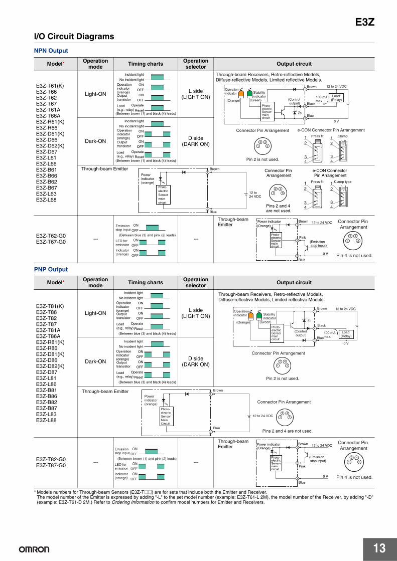
13
E3ZI/O Circuit Diagrams
NPN Output
PNP Output
* Models numbers for Through-beam Sensors (E3Z-T@@) are for sets that include both the Emitter and Receiver. The model number of the Emitter is expressed by adding "-L" to the set model number (example: E3Z-T61-L 2M), the model number of the Receiver, by adding "-D" (example: E3Z-T61-D 2M.) Refer to Ordering Information to confirm model numbers for Emitter and Receivers.
Model* Operation mode Timing charts Operation
selector Output circuit
E3Z-T61(K)E3Z-T66E3Z-T62E3Z-T67E3Z-T61AE3Z-T66AE3Z-R61(K)E3Z-R66E3Z-D61(K)E3Z-D66E3Z-D62(K)E3Z-D67E3Z-L61E3Z-L66E3Z-B61E3Z-B66E3Z-B62E3Z-B67E3Z-L63E3Z-L68
Light-ON L side(LIGHT ON)
Dark-ON D side(DARK ON)
E3Z-T62-G0E3Z-T67-G0 --- ---
Model* Operation mode Timing charts Operation
selector Output circuit
E3Z-T81(K)E3Z-T86E3Z-T82E3Z-T87E3Z-T81AE3Z-T86AE3Z-R81(K)E3Z-R86E3Z-D81(K)E3Z-D86E3Z-D82(K)E3Z-D87E3Z-L81E3Z-L86E3Z-B81E3Z-B86E3Z-B82E3Z-B87E3Z-L83E3Z-L88
Light-ON L side(LIGHT ON)
Dark-ON D side(DARK ON)
E3Z-T82-G0E3Z-T87-G0 --- ---
Incident light
No incident light
ON
OFF
ON
OFF
Operate
Reset
Operationindicator(orange)
(Between brown (1) and black (4) leads)
Outputtransistor
Load(e.g., relay)
12
34
Connector Pin Arrangement e-CON Connector Pin Arrangement
Pin 2 is not used.
Press fit Clamp
4
1
2 43
3
112 to 24 VDC Brown
Black(Controloutput)
Blue
100 mAmax.
Operationindicator Stability
indicator(Green)(Orange)
0 V
ZD
Load(Relay)
12
34
Photo-electricSensormaincircuit
Through-beam Receivers, Retro-reflective Models, Diffuse-reflective Models, Limited reflective Models.
Incident light
No incident light
ON
OFF
ON
OFF
Operate
Reset
Operationindicator(orange)
(Between brown (1) and black (4) leads)
Outputtransistor
Load(e.g., relay)
1
2 43
3
1Power indicator(orange)
e-CON Connector Pin Arrangement
12
34
Press fit Clamp type12
34
Connector Pin Arrangement
Pins 2 and 4 are not used.
12 to 24 VDC
Brown
Blue
Photo-electricSensormaincircuit
Through-beam Emitter
ON
OFF
ON
OFF
ON
OFF
Indicator(orange)
(Between blue (3) and pink (2) leads)
Emissionstop input
LED for emission
1
2 43
Connector PinArrangement
Pin 4 is not used.
1
2
30 V
12 to 24 VDCBrown
Pink
Blue
Power indicator(Orange)
Photo-electric Sensormaincircuit
(Emission stop input)
Through-beam Emitter
Incident light
No incident light
ON
OFF
ON
OFF
Operate
Reset
Operationindicator(orange)
(Between blue (3) and black (4) leads)
Outputtransistor
Load(e.g., relay) 4
1
2 43
1
30 V
ZD
Connector Pin Arrangement
Pin 2 is not used.
12 to 24 VDC Brown
Black
(Controloutput)
Blue
100 mAmax.
Operation indicator Stability
indicator(Green)(Orange)
Load(Relay)
Photo-electric Sensormaincircuit
Through-beam Receivers, Retro-reflective Models, Diffuse-reflective Models, Limited reflective Models.
Incident light
No incident light
ON
OFF
ON
OFF
Operate
Reset
Operationindicator(orange)
(Between blue (3) and black (4) leads)
Outputtransistor
Load(e.g., relay)
1
2 43
3
1Powerindicator(orange) Connector Pin Arrangement
Pins 2 and 4 are not used.
12 to 24 VDC
Brown
Blue
Photo-electricSensorMainCircuit
Through-beam Emitter
ON
OFF
ON
OFF
ON
OFF
(Between brown (1) and pink (2) leads)
Indicator(orange)
Emissionstop input
LED for emission
1
2 43
Connector PinArrangement
Pin 4 is not used.
1
2
30 V
12 to 24 VDCBrown
Pink
Blue
Power indicator(Orange)
Photo-electric Sensormaincircuit
(Emission stop input)
Through-beam Emitter

14
E3Z
Plugs (Sensor I/O Connectors)
Nomenclature
24
13
1234
BrownWhiteBlueBlack
Wire color
XS3F-M421-402-AXS3F-M421-405-AXS3F-M422-402-AXS3F-M422-405-A
Pin arrangement
Note: Pin 2 is not used.
Classifi-cation
Wirecolor
Connector pin No. Application
DC
Brown 1 Power supply (+V)
White 2 (Emission stop input)
Blue 3 Power supply (0 V)
Black 4 Output
E39-ECON@M
E39-ECONW@M
e-CON connectorM8 connector
Through-beam ModelsE3Z-T@@ (Emitter)E3Z-T@@A (Receiver)
Retro-reflective ModelsE3Z-R@@
E3Z-B@@
Diffuse-reflective ModelsE3Z-D@@
Narrow-beam Reflective ModelsE3Z-L@@
Limited reflective ModelsE3Z-L@@
Stability indicator(green)
Operation selector
Operation indicator(orange)Sensitivity adjuster

15
E3ZSafety Precautions
Refer to Warranty and Limitations of Liability.
This product is not designed or rated for ensuring safety of persons either directly or indirectly.Do not use it for such purposes.
Do not use the product in atmospheres or environments that exceed product ratings.
Wiring
M8 Metal Connector• Be sure to connect or disconnect the metal connector after turning
OFF the Sensor.• Hold the connector cover to connect or disconnect the metal
connector.• Secure the connector cover by hand. Do not use any pliers,
otherwise the connector may be damaged.• The proper tightening torque range is between 0.3 and 0.4 N·m. Be
sure to tighten the connector securely, otherwise the specified degree of protection may not be maintained or the connector may be disconnected due to vibration.
Mounting
Sensor MountingUse M3 screws to mount the sensor and tighten each screw to a maximum torque of 0.53 N·m.
Oil-resistant Models
Oil Resistance• Although the E3Z-@@@K Sensors have oil-resistant specifications,
performance may be affected by certain types of oil. Refer to the following table.
• E3Z-@@@K Sensors are tested for resistance to the oils given in the following table. Refer to the information in the table when deciding which type of oil to use.
Note: 1. The E3Z maintained a minimum insulation resistance of 100 MΩ after it was dipped in all the above oils for 240 hours.
2. When using the Sensors in environments subject to oils other than those listed above, use the figures for kinematic viscosity and pH from the table as general guidelines. Additives and other substances contained in oils may affect the E3Z. Be sure to consider this before use.
WARNING
Precautions for Correct Use
E3Z-@@@ E39-L104 Mounting Bracket(sold separately)
Test oil clas-sification Product name
Kinematic viscosity(mm2/s)at 40°C
pH
Lubricant Velocity No.3 2.02
---Water insolu-ble machining oil
Yushiron Oil No.2 ac Less than 10
Water soluble machining oil
Yushiroken EC50T-3
---
7 to 9.5Yushiron Lubic HWC68 7 to 9.9Gryton 1700D 7 to 9.2Yushironken S50N 7 to 9.8

16
E3ZDimensions
Sensors
* Models numbers for Through-beam Sensors (E3Z-T@@) are for sets that include both the Emitter and Receiver. The model number of the Emitter is expressed by adding "-L" to the set model number (example: E3Z-T61-L 2M), the model number of the Receiver, by adding "-D" (example: E3Z-T61-D 2M.) Refer to Ordering Information to confirm model numbers for Emitter and Receivers.
(Unit: mm)Tolerance class IT16 applies to dimensions in this data sheet unless otherwise specified.
Through-beam*Pre-wired ModelsE3Z-T61(K)E3Z-T81(K)E3Z-T61AE3Z-T81AE3Z-T62(-G0)E3Z-T82(-G0)
20
12
32.8
25.4
12.7
4 dia. vinyl-insulated round cable with 2 conductors (Conductor cross section: 0.2 mm2 (AWG24), Insulator diameter: 1.1 mm), Standard length: 2 m
Two, M3
Power indicator (orange)
Emitter
Lens
11
2.1
3131
10.8
7.2
Pins 2 and 4 are not used.
Terminal No.
Specifi-cations
1 +V2 ---3 0V4 ---
(Excluding -G0)
Pin 4 is not used.
Terminal No.
Specifi-cations
1 +V2 Input3 0V4 ---
(-G0)
6
15.8
18
4 dia. vinyl-insulated round cable with 2 or 3 conductors, Standard length: 2m
Press-fit e-CON Pre-wired Connector
4 dia. vinyl-insulated round cable with 2 or 3 conductors, Standard length: 0.3 m,0.5m, and 2m
15
5.9
15.64321
M12×1
1
32
4 dia. vinyl-insulated round cable with 2 or 3 conductors, Standard length: 0.3 m
4
M8 Pre-wired Connector(E3Z-T@@K-M3J)
4 dia. vinyl-insulated round cable with 2 or 3 conductors, Standard length: 0.3 m
M8
2 4
1 3
4321
Clamp-type e-CON Pre-wired Connector(E3Z-T61-ECON-C)
M12 Pre-wired Connector(E3Z-T@@-M1J)
* The Emitter cable has two conductors and the Receiver cable has three conductors.
2032.8
25.4
12.7
4 dia. vinyl-insulated round cable with 3 conductors (Conductor cross section: 0.2 mm2 (AWG24), Insulator diameter:1.1 mm), Standard length: 2 m
Two, M3
4.511.2
Stability indicator (green)
Operation Indicator (orange) 7.5
Sensitivity adjuster
Operation selector
Receiver
Lens
11
2.1
3131
10.8
7.2
Pin 2 is not used.
Terminal No.
Specifi-cations
1 +V
2 ---
3 0V
4 Output
Through-beam*Connector ModelsE3Z-T66E3Z-T86E3Z-T66AE3Z-T86AE3Z-T67(-G0)E3Z-T87(-G0)
M8 connector
10.4 Two, M3
Lens
11
Power indicator (orange)
9.75
Emitter
12
20202.1
12.7
3131
10.8
7.232.8
25.4
Pins 2 and 4 are not used.
Terminal No.
Specifi-cations
1 +V
2 ---
3 0V
4 ---
(Excluding -G0)
Pin 4 is not used.
Terminal No.
Specifi-cations
1 +V
2 Input
3 0V
4 ---
(-G0)
M8 connector
9.75
Lens
Stability indicator (green)
Operation Indicator (orange)
Sensitivityadjuster
Operation selector
Receiver
Two, M3
2.8
25.4
4.511.2
7.5
12.7
2020
10.8
7.2
10.4
11
2.1
3131
3
Pin 2 is not used.
Terminal No.
Specifi-cations
1 +V
2 ---
3 0V
4 Output

17
E3Z
Retro-reflective ModelsPre-wired ModelsE3Z-R61(K) E3Z-B61E3Z-R81(K) E3Z-B81E3Z-D61(K) E3Z-B62E3Z-D81(K) E3Z-B82E3Z-D62(K) E3Z-L63E3Z-D82(K) E3Z-L83E3Z-L61E3Z-L81
2.8
25.4
4 dia. vinyl-insulated round cable with 3conductors (Conductor cross section:0.2 mm2 (AWG24), Insulator diameter:1.1 mm), Standard length: 2 m
Stability indicator (green)
Two, M3
Sensitivity adjuster
Operation selector
Operation Indicator (orange)
2.1
3131
Receiver Lens 7 dia.
EmitterLens 7 dia.
2020
16.7
10.810.8
32.8
4.511.2
7.5
25.48
Terminal No.
Specifica-tions
1 +V
2 ---
3 0V
4 Output
Clamp-type e-CON pre-wired connectors (E3Z-@6@-ECON-C)
M8 Pre-wired Connector (E3Z-T@@K-M3J)
4 dia. vinyl-insulated round cable with 3 conductors, Standard length: 0.3 m
M8
2 4
1 3
M12×1
1
32
4 dia. vinyl-insulated round cable with 3 conductors, Standard length: 0.3 m
M12 Pre-wired Connector (E3Z-@@@-M1J)
4
Press-fit e-CON Pre-wired Connector
15
5.9
15.64 dia. vinyl-insulated round cable with 3 or 4 conductors, Standard length: 0.3 m, 0.5m, and 2m
6
15.8
18
4 dia. vinyl-insulated round cable with 3 conductors, Standard length: 2 m
4321
4321
Retro-reflective ModelsConnector ModelsE3Z-R66 E3Z-B66E3Z-R86 E3Z-B86E3Z-D66 E3Z-B67E3Z-D86 E3Z-B87E3Z-D67 E3Z-L68E3Z-D87 E3Z-L88E3Z-L66E3Z-L86
Stability indicator (green)
Two, M3
9.75
Receiver Lens 7 dia.
EmitterLens 7 dia.
Sensitivity adjuster
M8 connector
Operation selector
Operation Indicator (orange)
2020
16.7
10.810.8
10.4
2.1
3131
2.8
25.4
4.511.2
7.5
3
8
Terminal No.
Specifica-tions
1 +V
2 ---
3 0V
4 Output
Note: The lens for the E3Z-D@1/D@6/L@@/B@@ is red. The lens for the E3Z-D@2/D@7 is black.

18
E3Z
e-CON Connector Configurations
Accessories (Order Separately)
Mounting Brackets
Refer to E39-R for details.
Sensor I/O Connectors
Refer to XS2@ and XS3@ for details.
Wiring method Sensor connectors
Press-fit 37104-3122-000FL (made by Sumitomo 3M)
Clamp XN2A-1430 (made by OMRON)
SlitsE39-S65AE39-S65BE39-S65C
A
32.232.2
20.2
0.2-mm-thick
10.410.4
12.7
Model Size A MaterialE39-S65A 0.5 dia. SUS301
stainlesssteel
E39-S65B 1.0 dia.E39-S65C 2.0 dia.
SlitsE39-S65DE39-S65EE39-S65F
Model Size A MaterialE39-S65D 0.5 SUS301
stainlesssteel
E39-S65E 1.0E39-S65F 2.0
A
32.232.2 10
0.2-mm-thick
10.4
20.2
12.7
SlitsE39-L44
16.2
19.5
14.18.7
27
31.2
36
3
3
1.8
18
23.2
26.2
20°
(Mounting dimensions)SlitsE39-L104
6.7
7.0
1
4.5629
17.8
26.626.6
12.4
R2014°
21.5
39
10°
8.8
(Mounting dimensions)