culture tank design
DESCRIPTION
Aqua culture designs for tanks and other devicesTRANSCRIPT

1
About the only thing that aquacultural engineers can unanimously agree upon is that a body of water is required to raise fish. How this body of water should be contained is open to considerable debate. Should the fish be reared in ponds, raceways, or tanks? If tanks are chosen, to what geometry should the tank conform? How deep should a tank be or more descriptively, what should the tank diameter to depth ratio be? First, this module is restricted to tank culture and Recirculating Aquaculture Systems (RAS) technology. Therefore, we are only addressing tanks and not open ponds. Within that chosen focus, the paramount issue in all tank culture design is to maximize the capability of the tank system for self-cleaning. Without exception, the dominant reason RAS's fail is their inability to self-clean. A system that does not effectively and quickly remove manure from the culture water will never produce fish economically. All individual components of the system will fail to perform efficiently. Thus, the first question that one should ask is whether or not the tank will effectively clean.
Secondly, the capability to effectively manage the fish within the tank vessel is the next question that must be addressed. These and other issues will be addressed in this module. And for the stubborn, raceway design will also be reviewed briefly as will a newly designed hybrid of raceway and round tank concepts. All these concepts can be generally applied to either RAS or flow-through systems.
Culture Tank DesignCulture Tank Design
James M. Ebeling, Ph.D.James M. Ebeling, Ph.D.
Research EngineerResearch EngineerAquaculture Systems Technologies, LLCAquaculture Systems Technologies, LLC
New Orleans, LANew Orleans, LA
Michael B. Timmons Ph.D.Michael B. Timmons Ph.D.
J.Thomas Clark Professor ofJ.Thomas Clark Professor ofEntrepreneurship & Personal EnterpriseEntrepreneurship & Personal Enterprise
Cornell UniversityCornell University

2
Recirculating Aquaculture Systems Short Course
Stocking DensityStocking Density
Cdensity 1.5 for L in inches (0.24 for L in cm) for tilapia2.0 (0.32) for trout2.5 (0.40) for perch
densitydensity C
LD =
densitydensity C
LD =
One of the first questions that must be answered in designing a RAS is the number of fish that can be carried in the tank. The number of fish and their mass will define the feeding rates from which the individual engineering components are designed. The number of fish that can be stocked per unit volume (Ddensity, lbs/gal) will depend on both the fish species and the fish size. We have developed an approach that is based upon body length (L) to estimate the number of fish that can be carried per unit volumeof tank:
D density = L / C density
where:Cdensity 1.5 for L in inches (0.24 for L in cm) for tilapia
2.0 (0.32) for trout2.5 (0.40) for perch
These values were developed based upon experience originally with brook trout and were later adapted to tilapia. There is a tendency to over-stock smaller fish. Some of our experience indicates that tilapia can be stocked in much higher numbers while the animals are small. However, crowding is risky, as it can have severe consequences on small animals during their rapid growth stage, e.g., fish less than 5 inches (13 cm) in length. Visual observations can be misleading, since you will see only the active dominant fish. Sampling fish populations will be your best guide to whether or not your stocking densities are too high.
Good management should produce a population that has a standard deviation that is less than 10% of the population mean. If this value increases, it is indicative of over-stocking, under feeding, or other management problems.

3
Recirculating Aquaculture Systems Short Course
Stocking DensityStocking Density
0
50,000
100,000
150,000
200,000
250,000
1 2 3 4 5 6 7 8
Tanks per year
Gal
lons
per
100
,000
lb/y
r
50 g
200 g
500 g
1,000 g
Required tankage volume, fish harvest size, and the harvests per year (turnovers)
The relationship between required tankage volume, fish harvest size, and the harvests per year (turnovers) are shown above for tilapia. The reader can develop similar charts for other fish. For example, to grow 200 g animals in a year with 3 tanks, for every 100,000 lbs per year of production, you would need approximately 50,000 gallons of tankage.
The reader should also be aware at this point that the management methods used to maximize productivity from a given set of tanks can be quite inventive. For example, the simplest management method would be an "all-in and all-out" approach, where a tank is stocked with small fingerlings and then harvested once the fish reach target market size. Clearly, using this approach greatly under utilizes the rearing capacity of the tank, and for that matter, the water conditioning equipment associated with the system to maintain water quality at the highest feeding loads. Watten (1992) presented a mathematical analysis of the effects of sequential rearing on the potential production from the system. Generally, one would probably try to use at least three tank movements from fingerling to market size. Each time fish are moved, though, loss of growth and additional mortality due to stress will occur. It is this loss of productivity that actually limits the number of cohort movements from an economical standpoint, although the time and labor required to perform the movement are also important considerations. Other management methods to maximize the utilization of the RAS system would be to place several tanks on a common water treatment system where the fish are either left in the same tank they were stocked in or the fish are moved from one tank to the next as they increase in size. Any movement of fish is not a good thing and should be avoided by design whenever possible.

4
Recirculating Aquaculture Systems Short Course
Culture Tank EngineeringCulture Tank Engineering
Circular tanks make excellent culture vessels
• Improves the uniformity of the culture environment• Allow a wide range of rotational velocities to optimize fish
health and condition• Rapid concentration and removal of settleable solids.
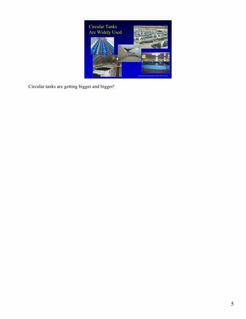
Circular tanks are getting bigger and bigger!
The production of food fish in large circular tanks has produced large cost savings in comparison to raising the same quantity of fish in more but smaller tanks. Larger circular culture tanks offer many advantages for food fish production. While just a few years ago, an 8 m diameter tank was considered large, now we are seeing 10 and 15 m and even larger diameter tanks being put into production. Substantial savings in both capital and labor costs can be realized by shifting production into fewer but larger culture tanks. Fundamentally, the time it takes to service a small tank or a large tank is similar. In fact, the capital costs associated with large versus small is not proportional to tank volume. Dramatic cost savings can be obtained by using larger and larger tanks. Circular tanks make good culture vessels for the following reasons:
•Improves the uniformity of the culture environment•Allow a wide range of rotational velocities to optimize fish health and condition•Rapid concentration and removal of settleable solids.
The flow inlet and outlet structures and fish grading and/or removal mechanisms should be engineered to reduce the labor requirements of handling fish and to obtain effective tank rotational characteristics, mixing, and solids flushing.
5
Recirculating Aquaculture Systems Short Course
Circular Tanks Circular Tanks Are Widely UsedAre Widely Used
Circular tanks are getting bigger and bigger!

6
Recirculating Aquaculture Systems Short Course
Culture Tank EngineeringCulture Tank Engineering
Tanks fail as units
• distributing flow to obtain uniform mixing and rapid solids removal• grading and harvesting fish• removing mortalities
• isolating the biofilter while treating the fish with a chemotherapeutant
Start small and build upon success!
Other Challenges of circular tanks
What is the downside of larger culture tank units? Tanks fail as units. Typically, you do not lose a part of a tank; instead you lose the entire tank of fish. Distributing a farm's population of fish among multiple tanks provides a measure of protection against entire farm failure. The more fish in a tank, the bigger the economic loss that will occur when a tank fails. However, as the experience of the management and design team increases, the risk of tank failure decreases, but should never be ignored. Itwould not be prudent to start out with large culture tank vessels, if this were your first RAS experience. Start small and build upon success. Other challenges of using large circular tanks include:
•distributing flow to obtain uniform mixing and rapid solids removal•grading and harvesting fish•removing mortalities•isolating the biofilter while treating the fish with a chemotherapeutant.
Large tanks are more critically dependent upon tank hydraulic design than are small tanks, because in small tanks, ≤ 1 m3, the overall rate of water exchange tends to be rapid. The rapid hydraulic exchange results in reasonably good water quality, because the high turnover rate (usually as rapid as 10 minutes per tank volume exchange, called hydraulic retention time, HRT) carries more oxygen into the tank and rapidly flushes wastes. Conversely, in large tanks, the HRT tends to be lower (around 30 minutes or greater) and, as a result, the inlet and outlet injection methods and flow rate become dominant factors affecting the uniformity of water conditions in the tank (aside from the feed loading rate). The carrying capacity of a tank is influenced by water exchange, feeding rate, oxygen consumption, and waste production.

7
Recirculating Aquaculture Systems Short Course
Round Tanks: AdvantagesRound Tanks: Advantages
• Advantages:• uniform environment• optimum rotational velocity
• for swimming fish• for self-cleaning attributes
• flow distributes feed & fish• rapid removal of wastes
Tanks are designed with considerations given to production cost, space utilization, water quality maintenance, and fish management. Circular tanks are attractive for the following reasons:
•simple to maintain•provide uniform water quality•allow operating over a wide range of rotational velocities to optimize fish health/condition•settleable solids can be rapidly flushed through the center drain•designs that allow for visual or automatic observation of waste feed to enable satiation feeding are possible

8
Recirculating Aquaculture Systems Short Course
Fewer But Larger Culture TanksFewer But Larger Culture Tanks• Reduce floor space requirements• Reduces cumulative cost of equipment:
• flow control valves • effluent stand-pipe structures• fish feeders• probes: oxygen, pH, temperature, ORP• flow, level switches
• Reduces labor:• time required to analyze water quality• distribute feed• perform cleaning chores
There is a definite trend towards large circular culture tanks for food fish production. Tanks larger than 10 m in diameter, which used to be referred to as pools, are now reasonable choices for culture systems in intensive indoor operations.

9
Recirculating Aquaculture Systems Short Course
Tank Design and Economies of ScaleTank Design and Economies of Scale
• Disadvantages of fewer but larger tanks:• larger economic risk with each tank loss
• mechanical problems• biological problems
• potential problems to overcome:• removing mortalities• grading and harvesting fish• controlling flow hydraulics
• water velocities, dead-spaces, and settling zones
Disadvantages of fewer but larger tanks include the larger economic risk with each tank lass due to mechanical or biological problems. Also the shear size of these tanks can make routine chores into large scale military maneuvers.

10
Recirculating Aquaculture Systems Short Course
Round Tanks: Diameter & DepthRound Tanks: Diameter & Depth
• Culture tanks can be large• between 12 to 42 m diameter• smaller tanks are used
• hatcheries • smaller farms
• Dia:Depth = 3:1 to 10:1• although silo tanks have been used
Recommended tank diameter to depth ratios vary from 5:1 to 10:1 (Burrows and Chenoweth, 1955; Chenoweth et al. 1973; Larmoyeux et al. 1973); even so, many farms use tanks with diameter:depth ratios as low as 3:1. Selection of a tank diameter:depth ratio is also influenced by factors such as the cost of floor space, water head, fish stocking density, fish species, and fish feeding levels and methods. Choices of depth should also consider ease of workers handling fish within the tank and safety issues of working in waters that may be more than "chest" high.
In the early years of RAS, tanks that were actually deeper than their diameter were touted as a key design factor to economic success. None of these systems were successful, mostly for problems related to fish management. Even in more modest attempts to utilize deeper tanks, e.g., a 3:1 ratio of diameter:depth, not all fish will effectively distribute into the entire water column. An example of this species specific attribute includes tilapia, which utilize the entire water column, versus walleye or flounder, which are surface area animals and do not utilize the water column nearly as effectively as tilapia.

11
Recirculating Aquaculture Systems Short Course
Round Tanks: Optimum VelocityRound Tanks: Optimum Velocity• Optimum swimming velocity
• = (0.5 to 2.0) x (fish body length)/second
• Velocities in a ‘donut-shaped’ region about tank center are reduced:• allows fish to select a variety of swimming speeds
The ability to self-clean is a key advantage of circular tanks. To establish this ability, the water column must be in constant rotation within the tank. The rotational velocity in the culture tank should be as uniform as possible from the tank wall to the center and from the surface to the bottom, and it should be swift enough to make the tank self-cleaning. However, it should not be faster than that required to exercise the fish. Water velocities of 0.5–2.0 times fish body length per second are optimal for maintaining fish health, muscle tone, and respiration (Losordo and Westers, 1994). Velocities required to drive settleable solids to the tank’s center drain should be greater than 15 to 30 cm/s (Burrows and Chenoweth, 1970; Mäkinen et al. 1988). For tilapia, Balarin and Haller (1982) reported an upper current speed of 20–30 cm/s.
In circular tanks, velocities are reduced somewhat away from the walls, which allow fish to select a more comfortable water velocity, as compared to raceway designs where velocities are uniform along the channel. Water velocities in round tanks are, to a large degree, controllable independently of the water exchange rate, in contrast with raceways. The most critical factor, according to Tvinnereim and Skybakmoen (1989), is the design of the inlet and outlet arrangements. Properly designed inlet intake-outlet provisions also contribute to self-cleaning characteristics. Although round tanks are not as efficient in the utilization of floor space and are more difficult with respect to fish handling/harvesting (fish cannot be cornered) than raceways, they have a number of important advantages. They provide cheaper rearing space and they can be operated at low water exchange rates while still creating desirable velocities, hydraulic patterns and self-cleaning characteristics. Round tanks can also receive very high DO inputs without creating "hot spots" and they can be easily equipped with feeders, requiring only one, or at most a few feeding stations. With round tanks it is often possible to accomplish the maximum cumulative oxygen consumption (COC) within a single rearing unit. In other words, the water is "used up" after passing through one tank instead of a series of two or three. All units can, therefore, be placed on the same elevation level.

12
Recirculating Aquaculture Systems Short Course
Round Tanks: Radial FlowRound Tanks: Radial Flow
• Primary rotating flow creates secondary radial flow:• transports settleable solids to bottom center• creates self-cleaning tank
Circular tanks can achieve relatively complete mixing, i.e., the concentration of a dissolved constituent in the water flowing into the tank changes instantaneously to the concentration that exists throughout the tank. Therefore, if adequate mixing can be achieved, all fish within the tank are exposed to the same water quality. Good water quality can be maintained throughout the circular culture tank by optimizing the design of the water inlet structure and by selecting a water exchange rate so that the limiting water quality parameter does not decrease production when the system reaches carrying capacity.
The water inlet and outlet structures and fish grading and/or removal mechanisms should be engineered to reduce the labor requirement for fish handling and to obtain uniform water quality, rotational velocities, and solids removal within the circular tank. There is nothing more irritating than pipes and other devices that are in the way, when it is time to harvest a tank. Such obstructions also may decrease the effectiveness of the self-cleaning attributes of round tank culture in the first place. It is useful to visually inspect a tank being operated without fish to ensure that the tank water is effectively rotating and the presence of any dead zones can be noted and eliminated. Also, inlet structures can be installed for ease of removal during harvesting procedures, when generally supplemental aeration devices are operated as well.
Circular tanks are operated by injecting water flow tangentially to the tank wall at the tank outer radius so that the water spins around the tank center, creating a primary rotating flow. The no-slip condition that exists between the primary flow and the tank’s bottom and side walls creates a secondary flow that has an appreciable inward radial flow component at the tank bottom and an outward radial flow at the tank surface. This inward radial flow along the bottom of the tank carries settleable solids to the center drain and thus creates the self-cleaning property so desired in circular tanks. Unfortunately, in a circular tank with such flow, an area near the center drain region will become an irrotational zone with lower velocities and poor mixing, resulting in solids settling onto the floor. The magnitude of the irrotational zone depends on the introduction of tangential flows near the walls, the diameter:depth ratio, and the overall rate of flow leaving the center bottom drain. Because this irrotational zone has lower water velocities and does not mix well, it can decrease the effective use of the culture tank by producing short circuiting of flow, by creating localized water quality gradients (especially of concern are reduced oxygen levels), and by providing a quiescent zone where solids can settle and collect.

13
Recirculating Aquaculture Systems Short Course
Round Tanks: SelfRound Tanks: Self--Cleaning ActionCleaning Action
• Circular tanks self-clean, due to:• swimming motion of fish
• tank rotation every 60-90 sec
• creates rotational velocities > 15 - 30 cm/s
• tank rotation controls “tea-cup effect”
primary rotating flow
secondary radial flow
The degree to which a circular tank can self-clean is in part related to the overall rate of flow leaving the center bottom drain. Further, effective solids removal also depends upon the fish re-suspending the settled materials through their movements. This explains in part why tanks with low fish biomass do not clean as well as tanks with higher biomass. In addition, because aquaculture solids have specific gravities that are relatively close to that of water (typically 1.05–1.20 vs. 1.00 for water), sloping the floor towards the center drain does not improve the self-cleaning attributes of a circular tank. Sloped floors are useful only when a circular tank is drained for maintenance purposes.
14
Recirculating Aquaculture Systems Short Course
Round Tanks: Flow InjectionRound Tanks: Flow Injection
• Impulse force created by inlet flow • controls rotational velocity!• dependent on:
• inlet flow rate• velocity of inlet flow
• can be adjusted by selecting size and number of inlet openings
• alignment of inlet flow
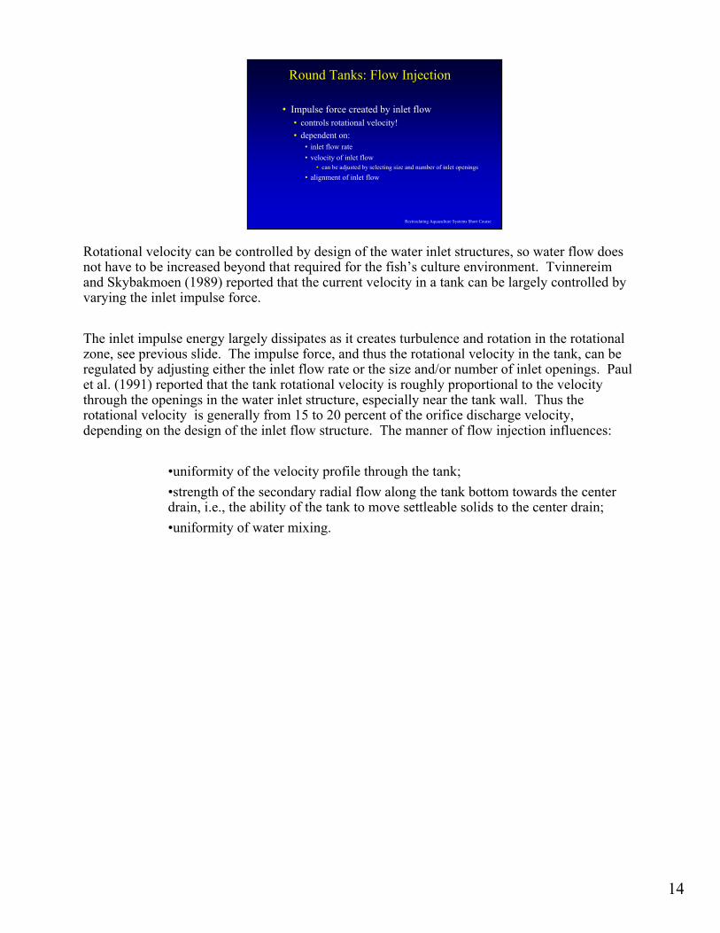
Rotational velocity can be controlled by design of the water inlet structures, so water flow does not have to be increased beyond that required for the fish’s culture environment. Tvinnereimand Skybakmoen (1989) reported that the current velocity in a tank can be largely controlled by varying the inlet impulse force.
The inlet impulse energy largely dissipates as it creates turbulence and rotation in the rotational zone, see previous slide. The impulse force, and thus the rotational velocity in the tank, can be regulated by adjusting either the inlet flow rate or the size and/or number of inlet openings. Paul et al. (1991) reported that the tank rotational velocity is roughly proportional to the velocity through the openings in the water inlet structure, especially near the tank wall. Thus the rotational velocity is generally from 15 to 20 percent of the orifice discharge velocity, depending on the design of the inlet flow structure. The manner of flow injection influences:
•uniformity of the velocity profile through the tank;•strength of the secondary radial flow along the tank bottom towards the center drain, i.e., the ability of the tank to move settleable solids to the center drain; •uniformity of water mixing.

15
Recirculating Aquaculture Systems Short Course
Round Tanks: Flow InjectionRound Tanks: Flow Injection
• Inlet flow injection w/ open-ended pipe:• poor mixing • higher velocities at
tank wall• poor solids flushing
• Inlet flow injection w/ vertical & horizontal pipes:• more uniform mixing• less flow short-circuiting
along tank bottom• more effective solids flushing
Open-ended pipe inlets create non-uniform velocity profiles in the tank, e.g., much higher velocity profiles along the tank wall; poor mixing in the irrotational zone, resuspension of solids throughout all tank depths; and poor flushing of solids from the bottom. Horizontal submerged pipe inlets improve water mixing effectively throughout the tank, but create a weaker and less stable bottom current (for solids cleaning). Vertical submerged inlet distribution pipes provide better self-cleaning than when injecting the water flow through an open-ended pipe or a horizontal distribution pipe, but the stronger bottom current (responsible for particle removal) also results in poorer mixing in the irrotational zone and short circuiting and therefore less efficient use of the flow exchange.
Maximum uniformity in tank water conditions can be obtained by using an inlet flow distribution pipe that combines both vertical and horizontal branches. The inlet pipes must be placed somewhat away from the wall so that fish can swim between the pipe and wall.
For large circular tanks, e.g., diameter > 6 m, placing multiple flow distribution pipes at different tank locations can improvesolids removal, velocity uniformity, and water quality homogeneity. Again, perform visual observations prior to fish placement.Recent experience indicates that by using only vertical inlet pipes and then pointing the exhaust jets at approximately 45° from the tank wall is reasonably effective. This may produce a flow pattern in the tank effective enough to eliminate the need for any horizontal inlet pipes. The horizontal pipes will interfere more with harvesting and sampling activities than would just the vertical pipes near the tank wall.

16
Recirculating Aquaculture Systems Short Course
Outlet Flow StructuresOutlet Flow Structures
external pipe with oblong slots at base or with a gap between the pipe and the floor (neither shown)
outlet flow
inlet flow top of the internal stand-pipe functions as a weir to control tank water level
inlet flow effluent stand-pipe
culture tank
Circular fish culture tanks concentrate settleable solids, e.g., fecal matter, feed fines, and uneaten feed, at their bottom and center. The tank center is then the logical location for the bottom drain. The bottom center drain should be designed to continuously remove the concentrated settleable solids and for the intermittent removal of dead fish that are captured at the bottom center drain (discussed more fully latter). The bottom center drain structure is also used for water level control by connecting it to a weir, either on the inside, left, or the outside of the tank, above right.

17
Recirculating Aquaculture Systems Short Course
““Cornell typeCornell type”” DualDual--Drain Culture TanksDrain Culture Tanks
Circular fish culture tanks can be managed as swirl settlers, i.e., settling basins with two effluents, because of their capability to concentrate solids at their bottom and center. Solids that concentrate at the bottom center can be removed in a small flow stream by using a bottom-drawing center drain, while the majority of flow is withdrawn at an elevated drain. Cobb and Titcomb (1930) and Surber (1936) were the first to report the use of a second bottom-drawing drain to remove solids that were settled in the center of circular culture tanks. More recently, settled solids have been reportedly concentrated in 5–20% of the total flow that leaves the bottom center drain of circular culture tanks when the remainder of the flow leaving the tank (roughly 80–95% of the total) was withdrawn through a fish-excluding port located above the bottom-drawing drain (Mäkinen et al. 1988; Eikebrokk and Ulgenes, 1993; Lunde et al. 1997).
18
Recirculating Aquaculture Systems Short Course
Concentrate Solids at the Culture TankConcentrate Solids at the Culture Tank
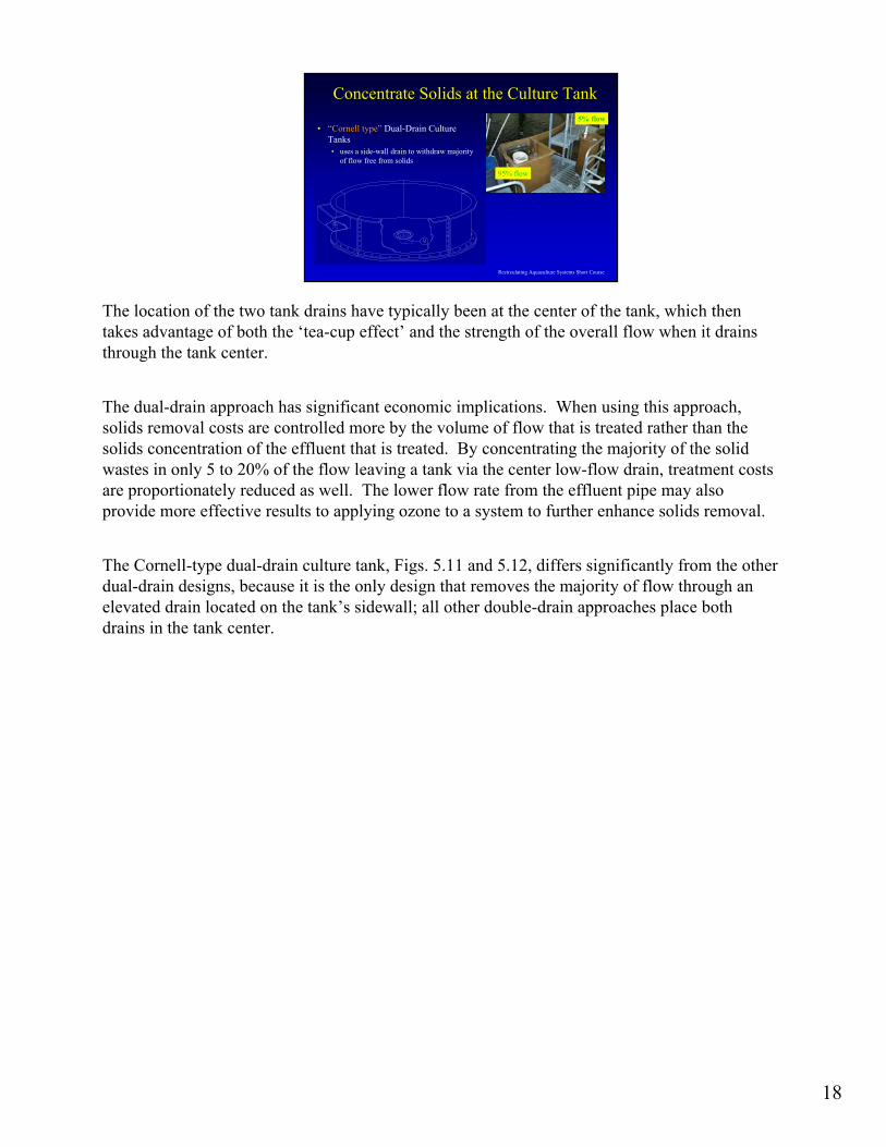
• “Cornell type” Dual-Drain Culture Tanks• uses a side-wall drain to withdraw majority
of flow free from solids
95% flow
5% flow
The location of the two tank drains have typically been at the center of the tank, which then takes advantage of both the ‘tea-cup effect’ and the strength of the overall flow when it drains through the tank center.
The dual-drain approach has significant economic implications. When using this approach, solids removal costs are controlled more by the volume of flow that is treated rather than the solids concentration of the effluent that is treated. By concentrating the majority of the solid wastes in only 5 to 20% of the flow leaving a tank via the center low-flow drain, treatment costs are proportionately reduced as well. The lower flow rate from the effluent pipe may also provide more effective results to applying ozone to a system to further enhance solids removal.
The Cornell-type dual-drain culture tank, Figs. 5.11 and 5.12, differs significantly from the other dual-drain designs, because it is the only design that removes the majority of flow through an elevated drain located on the tank’s sidewall; all other double-drain approaches place both drains in the tank center.

19
Recirculating Aquaculture Systems Short Course
Mixing in Mixing in ‘‘CornellCornell--typetype’’ TanksTanks
irrotationalzone
irrotationalzone
• Need to minimize irrotational zone to avoid:• poorer mixing• lower velocities & solids depositing on tank bottom
• Note, irrotational zone provides excellent settling
Using the Cornell-dual drain design basically eliminates the ever present vortex usually created when both flows are extracted from the center of round tanks. The Cornell-dual drain also reduces the velocities near the center drain because the flow leaving the center drain is only 5 to 20% of the total flow from the tank. As a result, fish distribution is much more uniform in a Cornell dual-drain compared to conventional double drains. This is a key advantage because the fish effectively utilizes the entire tank volume. In a conventional dual-drain tank, it is not uncommon to see the center third of the tank being unoccupied by fish. The Freshwater Institute has adapted a dead fish removal system to the Cornell-dual-drain design where the center drain (low-flow) can periodically be flushed and in the process carry away any dead fish that have collected.

20
Recirculating Aquaculture Systems Short Course
Bottom Drain FlushingBottom Drain Flushing
• Solids deposit about center drain occurs more often @• 1 ex/hr (rarely @ 2 ex/hr), • > dia:depth (e.g.,12:1), • lower % bottom flows (@ 5%).
• Dia:Depth of 3:1 & 6:1 had few deposits• 2 ex/hr -- BEST
Total suspended solids (TSS) concentrations were also measured in bottom and sidewall discharges and in the effluent from a commercial microscreen filter treating the bottom flow. Mean results from data collected at the Freshwater Institute indicated that the Cornell-type double-drain tank concentrated the majority of TSS in the bottom flow. The TSS concentration discharged through the bottom drain averaged 19.6 ± 3.6 mg/L (± standard error), while the TSS concentration discharged from the sidewall averaged only 1.5 ± 0.2 mg/L. This represents a 13 fold increase in solids concentration from the center drain. Practically speaking, the side wall drain discharges the best water quality in terms of suspended solids, since the solids are constantly moving towards the center drain and influent water also enters from the outside edge of a tank. The sidewall discharge, which represented 80–95% of the total flow, but only 1.5 mg/L TSS, would probably not require any further treatment and most likely could be discharged directly under most state and federal regulations. Further treatment of the bottom discharge across a commercial microscreen filter then captured 82% (± 4%) of the TSS in the bottom discharge, so that only an average of 3.5 ± 0.8 mg/L TSS would be discharged with the bottom flow.
When a center standpipe is used on the inside of a tank, it can be designed so that it either captures and stores settleable solids near the drain (where they can be flushed at intervals, or it continuously withdraws settleable solids from the bottom of the culture tank. To continuously withdraw settleable solids through a center standpipe that also controls water depth requires use of two concentric pipes. Perforated slots at the base of the outer pipe or a gap at the base of the outer pipe forces flow to be pulled from the bottom of the tank (capturing settleable solids) and the inner pipe is used as a weir to set the water depth within the tank.
As early as 1933, the use of self-cleaning center standpipe had been presented in the literature (Surber, 1933 & 1936). The recommended design is to create an adjustable gap between the bottom of the outer pipe and the tank bottom in order to increase suction while forcing the flow to leave at the tank bottom where settleable solids collect. The distance between the two pipes, i.e., the annular space should be selected to create a velocity large enough (0.3 to 1.0 m/s depending upon the size and density of the particles) to entrain solids up to the top of the inner pipe. A patented method that incorporates these principles uses an annular approach plate to enhance particle entrapment, above.

21
Recirculating Aquaculture Systems Short Course
Exclusion ScreenExclusion Screen
• Corrosion-resistant screening material, such as perforated sheets of aluminum, stainless steel, fiberglass, or plastic are used to cover drain outlets.
15 g and larger12.7 x 19.1
2.3 to 15 g6.4 x 12.7
0.45 to 2.3 g3.2 x 6.4
fry to 0.45 g1.6 x 3.2
Fish size, gSlot Size (mm)
Rule of Thumb
Water velocity through the screen is ≤ 30 cm/s.
When an external standpipe controls water depth, a vertical perforated plate or screen, can be used to cover the bottom center drain; this allows solids to leave the tank but excludes fish. Corrosion-resistant screening material, such as perforated sheets of aluminum, stainless steel, fiberglass, or plastic are used to cover drain outlets. We recommend using perforated screening with horizontal oblong slots instead of holes, because the slots are easier to clean, provide greater open area, and do not clog as readily as round holes. Guidelines for slot size based upon fish size are given in the Table above. Ideally, openings through the screen covering the center drain should be small enough to exclude fish and yet large enough not to become clogged with feed pellets or fecal matter. Entrapment of fish on the outlet occurs when fish cannot escape the area in front of the drain because the water velocity in that area is too great. Fish impingement is minimized by providing a total open area through the outlet screen so that the water velocity through the screen is ≤ 30 cm/s. Depending upon the species and life stage, certain situations particularly with smaller fish require water velocities ≤ 15 cm/s, e.g. These velocities do not produce a significant pressure drop through the screen openings, thus minimizing fish impingement.

22
Recirculating Aquaculture Systems Short Course
Design Suggestions for CornellDesign Suggestions for Cornell--Type TankType Tank
• Orientation of inlet jets is critical for mixing & solids flushing.
• Design 0.6-1.2 m water pressure behind inlet jets
• Size center drain o.d. > 10% tanks
• Size open area for center & side drains to provide 15-30 cm/s velocity.
"Rule of Thumb“
Choose the Center Drain Flow as the largest of: a) 0.15 gpm/ft2 (6 Lpm/m2) of floor,b) HRT center drain < 200 minutes, orc) 10 to 15% of total tank flow rate.
"Rule of Thumb“
Choose the Center Drain Flow as the largest of: a) 0.15 gpm/ft2 (6 Lpm/m2) of floor,b) HRT center drain < 200 minutes, orc) 10 to 15% of total tank flow rate.

23
Recirculating Aquaculture Systems Short Course
DualDual--Drain TanksDrain Tanks
Concentrate settleable solidsachieves large economic benefits
reduces capital costs and space requirements for downstream solids removal units
solids capture efficiency increases as inlet TSS increases!
When using the Cornell Double-Drain approach, the bottom flow is only 5–20% of the total tank discharge, so it would be possible and practical to further treat this flow with finer microscreen filters or by using settling tanks, wetlands, or sand filters, if required to meet stringent state or federal discharge regulations. Therefore, conventional flow-through systems that use circular culture tanks installed with the Cornell-type dual drain configuration can capture more of the waste solids and phosphorus from the water flow than can be captured within typical raceways operation that contain quiescent zones and off-line settling ponds.
Additionally, when the Cornell-type dual drain tank is used within partial-recirculating systems, these systems are capable of supporting high production densities while providing uniformly healthy water quality, optimized water velocities, and efficient, rapid, and gentle solids removal (Freshwater Institute, unpublished data). This type of partial recirculating system would be able to capture approximately 80–95% of the total waste solids produced, which is significantly better waste capture than is typically achieved within raceways operated under serial water reuse, e.g., 50% solids capture (Mudrak, 1981). Also, the solids filter treating the discharge from the partial-reuse system could be relatively small and inexpensive in comparison to a similar unit scaled to treat the much larger flow discharged from a raceway operation of relatively similar annual fish production. These combinations of treatment methodology offer a powerful approach to effective and efficient waste stream control from intensive culture systems.

24
Recirculating Aquaculture Systems Short Course
RacewaysRaceways
Raceways have primarily been associated with the culture of salmonids. Continued attempts have been made to adapt raceway culture methods to RAS, with mixed results. Proponents of raceways will generally argue for raceway design due to their better utilization of floor space and easier handling and sorting of fish. Their disadvantage is their inability to be self-cleaning.
Raceways are the most common rearing tank design being used in locations where aquaculture has tapped into huge groundwater resources, such as the Thousand Springs area in Idaho where large amounts of rainbow trout are produced. In Idaho, raceway dimensions are typically about 3–5.5 m wide, 24–46 m long, and 0.8–1.1 m deep (IDEQ, 1998). Raceways usually have a length to width ratio of 1:10 and a depth < 1.0 m, and require a high water exchange rate, e.g., one tank volume exchange every 10 to 15 minutes.

25
Recirculating Aquaculture Systems Short Course
Raceways (plug flow reactors)Raceways (plug flow reactors)
• Advantages:• Excellent footprint utilization
• Efficient and easy handling & sorting
• Disadvantages:• Water quality gradient (DO)
• Low velocity (not self cleaning)
Raceways have been used for years for the production of salmonids and other species by federal and state agencies for stocking purposes and commercial growers. Where there are large ground water resources, raceways are the most common rearing tank design being used to grow the majority of rainbow trout produced in the USA. One significant advantage of raceways is their better utilization of floor space and easier handling and sorting of fish as compared to circular tanks. Their primary disadvantages are the large volume of water required for maintaining water quality and their limited self-cleaning ability (Timmons et al. 1998). Water enters the raceway at one end and flows through the raceway in a plug-flow manner. As a result, the best water quality is found at the head of the raceway where the water first enters and then it deteriorates steadily towards the raceway outlet. Because of the low velocities through the raceway (2-4 cm/s), removal efficiency of settled solids is very poor, requiring frequent cleaning and maintenance tasks (Timmons et al. 1998). This is due to the hydraulic design being based on oxygen design requirements, rather than cleaning requirements, that result in the much lower velocities. In practical terms, raceways are incapable of producing the optimum water velocities recommended for fish health, muscle tone, and respiration (Timmons et al. 2002). Even using lower exchange rates and lower velocities, use of raceways is being severely limited due to the unavailability of large quantities of high quality water, increased concern about their environmental impacts on receiving waters, and the difficulty in treating the large flows producing a large effluent discharge

26
Recirculating Aquaculture Systems Short Course
Raceways ManagementRaceways Management
• based on oxygen loading requirements• loading velocity = 2 to 4 cm/s
• not on solids flushing requirements• solids flushing velocity = 15 to 30 cm/s
• DO loading velocity << solids flushing velocity
• fish sweep solids slowly down raceways
Raceways depend upon this high turnover rate to maintain sufficient water quality for fish growth. Water enters the raceway at one end and flows through the raceway in a plug-flow manner, with minimal back mixing. As a result, the best water quality exists at the head of the tank where the water enters, and then deteriorates steadily along the axis of the raceway towards the outlet. It is not be uncommon to see fish crowded towards the inlet end of the raceway in order to obtain oxygen, or at the end of a raceway to avoid high concentrations of ammonia or some other accumulating contaminant. During feeding activities, fish will also crowd to the feeders, since it is also more difficult to distribute feed throughout raceways than it is in circular tanks.
Velocity through the raceway will generally be between 2–4 cm/s, which is insufficient to effectively remove settled solids from the rearing space. Thus, frequent maintenance for cleaning of raceways is required. A variety of mechanisms can be used to increase solids removal, such as placing periodic baffles across the raceway to artificially increase velocity (20 to 40 cm/s or 10 times the raceway average water velocity) and sweeping action. However, these baffles must be moved to work the fish, and also provide a substrate for biosolids growth in warmer temperatures. In practice, the management of raceways is based on their oxygen design requirements, rather than their cleaning requirements. The velocity required to flush solids from unbaffled raceways is much greater than the velocity required to supply the oxygen needs of the fish. In practical terms, raceways are incapable of producing the optimum water velocities recommended for fish health, muscle tone, and respiration.

27
Recirculating Aquaculture Systems Short Course
Concentrate Solids in the RacewayConcentrate Solids in the Raceway
• Quiescent zones in the raceways:• screened to exclude fish• collect and store settleable solids swept from fish rearing
areas
quiescentzone
quiescentzone
Since the difference between flow rates necessary to achieve a cleaning velocity and required flows for oxygen supply are so different, designs are based upon minimizing cross-sectional area to promote maximum water velocity. As a result, many raceway systems are operated in series, with the discharge of the upstream raceway serving as the inflow water of the next one downstream. Water may be treated between race sections to restore a particular water quality parameter for subsequent downstream utilization or removal, e.g., oxygen addition, CO2 removal. Low head Oxygenators (LHO's) have become popular in such applications (Watten, 1989). LHO’s vary in configuration, but all are fundamentally similar in operation.
Raceways can be constructed side-by-side, with common walls, for maximizing the utilization of floor space and reducing construction cost. However, when constructed without common walls, because of their large aspect ratio (L:W), raceways require 1.5 to 2.0 times as much wall length as circular tanks. Circular tanks can also better structurally handle the weight of the confined water and can thus use thinner walls than rectangular tanks.
A quiescent zone devoid of fish is usually placed at the end of a raceway tank to collect the settleable solids that are swept out of the fish rearing area. At many large trout farms, these solids collection zones are the primary means for solids removal to meet discharge permit requirements. The maintenance of these settling zones can often be 25% of the total labor required for the entire fish operation.

28
Recirculating Aquaculture Systems Short Course
Concentrate Solids in the RacewayConcentrate Solids in the Raceway• Settled solids removal from quiescent zones:
• most often suctioned out with a vacuum pump• as often as every 1 to 3 days• as infrequently as bimonthly
• also washed out through a floor drain
cleanedvacuum
The settled solids are most often suctioned with a vacuum pump from the quiescent zones.

29
Recirculating Aquaculture Systems Short Course
MixedMixed--cell Racewaycell RacewayBest of Both World (Round Tanks & Raceways)
• Efficient footprint utilizations
• Efficient and easy handling & sorting
• Good self cleaning velocities
• Optimal velocities for fish
It should be fairly evident to the reader at this point that we strongly favor circular tanks because of their advantages of elevated water velocities, uniform water quality, and good solids removal characteristics. Still, we acknowledge that linear raceways make better use of floor space and facilitate harvesting, grading, and flushing operations. The cross-flow tank is a recent hybrid design that incorporates the desirable characteristics of both circular tanks and linear raceways (Watten and Johnson, 1990). Water is distributed uniformly along one side of a cross-flow tank via a submerged manifold and is collected in a submerged perforated drain line running the length of the opposite side.
The basis for this design is that the influent is jetted perpendicular to the water surface with sufficient force to establish a rotary circulation about the longitudinal direction. As a result, the standard raceway section is modified to create a series of horizontal counter rotating mixed cells with cell length equal to vessel width. Cells receive water from vertical pipe sections extending to the tank floor and positioned in the corners of the cells using jets that direct water into the cell tangentially to establish rotary circulation. The pipe sections can be swung up and out of the water during fish crowding or grading operations. Water exits each cell through a centrally located floor drain.
Hydraulic characteristics for a mixed cell raceway approximate that of a circular tank (mixed-flow reactor), both with and without fish present. Water velocities were reasonably uniform from top to bottom in the water column and were sufficient to scour and purge fecal solids. Cell interaction was significant with cell to cell exchange rates representing about 3 to 4 times the tank inflow rate. This characteristic contributed to the observed uniform distribution of fish throughout the vessel. The energy requirement of the design was 1.32 m of water head primarily for the inlet system and jets. Given that the tank center drain in each cell is similar to that of a circular tank, the Cornell-double drain could also be applied in this design. Before implementing this design, please recognize that there will be some additional construction costs associated with this raceway design, and performance over the long-term is yet to be established.
30
Recirculating Aquaculture Systems Short Course
Engineering DesignMixed-cell RacewayEngineering DesignEngineering DesignMixedMixed--cell Racewaycell Raceway
Pump
Pump
PumpPump
PumpPump
4” Manifold Pipe
SRTANK
Sludge Disposal
Sump &Settling w/Stirring Pump
Harvest byscreen capture
6” drain line
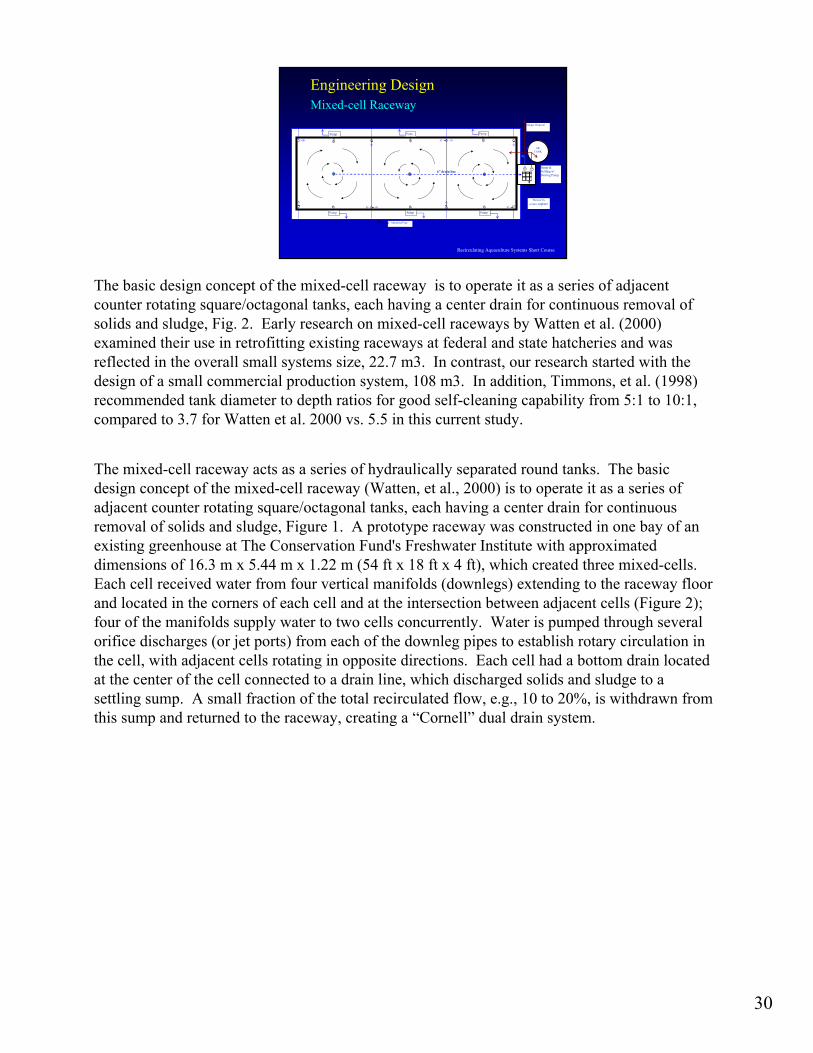
The basic design concept of the mixed-cell raceway is to operate it as a series of adjacent counter rotating square/octagonal tanks, each having a center drain for continuous removal of solids and sludge, Fig. 2. Early research on mixed-cell raceways by Watten et al. (2000) examined their use in retrofitting existing raceways at federal and state hatcheries and was reflected in the overall small systems size, 22.7 m3. In contrast, our research started with the design of a small commercial production system, 108 m3. In addition, Timmons, et al. (1998) recommended tank diameter to depth ratios for good self-cleaning capability from 5:1 to 10:1, compared to 3.7 for Watten et al. 2000 vs. 5.5 in this current study.
The mixed-cell raceway acts as a series of hydraulically separated round tanks. The basic design concept of the mixed-cell raceway (Watten, et al., 2000) is to operate it as a series of adjacent counter rotating square/octagonal tanks, each having a center drain for continuous removal of solids and sludge, Figure 1. A prototype raceway was constructed in one bay of an existing greenhouse at The Conservation Fund's Freshwater Institute with approximated dimensions of 16.3 m x 5.44 m x 1.22 m (54 ft x 18 ft x 4 ft), which created three mixed-cells. Each cell received water from four vertical manifolds (downlegs) extending to the raceway floor and located in the corners of each cell and at the intersection between adjacent cells (Figure 2); four of the manifolds supply water to two cells concurrently. Water is pumped through several orifice discharges (or jet ports) from each of the downleg pipes to establish rotary circulation in the cell, with adjacent cells rotating in opposite directions. Each cell had a bottom drain located at the center of the cell connected to a drain line, which discharged solids and sludge to a settling sump. A small fraction of the total recirculated flow, e.g., 10 to 20%, is withdrawn from this sump and returned to the raceway, creating a “Cornell” dual drain system.

31
Recirculating Aquaculture Systems Short Course
Engineering Design Mixed-cell RacewayEngineering Design Engineering Design MixedMixed--cell Racewaycell Raceway
10 cm manifold
threaded bushing 3.18 cm by 2.54 cm with a 2.54 cm threaded plug - drilled
15 cm drain line
5 cm gate valve
5 cm unions
5 cm vertical manifold
20 ml HDPE liner 15 cm drain with 5 cm orifice
5.44 m
1.22 m
Water Depth
manometer0.75 kW pump
check valve
top plate
Sidewall modules
A prototype raceway was constructed in an existing greenhouse with approximated dimensions of 16.3 m x 5.44 m x 1.22 m (54 ft x18 ft x 4 ft), which created three mixed-cells (Ebeling, et al. 2005). The basic design concept was to operate the raceway as a series of square/octagonal tanks, each having a center drain for continuous removal of solids and sludge. Each cell received water from four vertical manifolds (downlegs) extending to the raceway floor and located in the corners of each cell and at the intersection between adjacent cells (Fig. 3); four of the manifolds supply water to two cells concurrently. Water is pumped through several orifice discharges (or jet ports) from each of the downleg pipes to establish rotary circulation in the cell, with adjacent cells rotating in opposite directions. Each cell had a bottom drain located at the center of the cell connected to a drain line, which discharged solids and sludge to a settling sump.

32
Recirculating Aquaculture Systems Short Course
ConstructionConstruction –– GreenhouseGreenhouse
16.3 m x 5.44 m x 1.22 m16.3 m x 5.44 m x 1.22 m(18 ft x 56 ft x 4 ft).(18 ft x 56 ft x 4 ft).
20 ml HDPE Liner20 ml HDPE Liner
Due to construction limitations imposed by the greenhouse, the mixed cell raceway was constructed as an above ground tank the width of one bay, with approximate dimensions of 16.3 m x 5.44 m x 1.22 m (18 ft x 56 ft x 4 ft). Sidewall modules (1.22m 2.44m) were prefabricated of 2x6 construction studs on 24” spacing and covered with ½” plywood sheeting. These sidewall modules were then supported on a 6x6 treated wood beam ‘foundation’ and connected together with ½” lag bolts. In addition, a top plate was used to provide additional rigidity to the sidewall modules. Normally such a tank would be constructed below grade, allowing for structural support of the walls with backfill material. To provide this structural support, a series of polypropylene-impregnated wire rope were run across the top of the tank at five equally spaced intervals and also below the tank. In addition, a single cable was strung the length of the tank top and a second one below the insulated floor. These cables were secured into the sidewall top plates and the 6x6 treated wood beam foundation with eyebolts and forged galvanized steel hook and eye turnbuckles to allow adjusting and tightening. These proved quite adequate, but only after several failed attempts with lighter gauge materials. The message here is to never underestimate the structural requirements and the large pressures exerted by a tank of water.
The tank was lined with a 20 ml high density cross laminated polyethylene (HDPE) raceway liner from Permalon, Reef Industries, Inc.
The floor of the raceway was covered with approximately 5 cm of fine sand and graded to provide a slight slope to the three center drains. To minimize heat loss through the sidewalls, these were insulated with 2.54cm x 1.22m x 2.44m foam insulation board. To minimize heat loss through the ground, the outside perimeter of the floor was covered with 5.0cm x 1.22m x 2.44m insulation board and the center strip of the floor with 2.54cm x 1.22m x 2.44m insulation board. The tank was lined with a 20 ml high density cross laminated polyethylene (HDPE) raceway liner from Permalon, Reef Industries, Inc.

33
Recirculating Aquaculture Systems Short Course
Water Distribution SystemWater Distribution System
Sump TankSump Tank•• water levelwater level•• harvestingharvesting•• solids managementsolids management
Water Distribution ManifoldWater Distribution Manifold
A 15.24 cm (6 in) drainline with three discharge drains (tee fittings) centered on each of the three cells was buried along the longitudinal axis of the tank. A standard flange socket fitting was modified by boring out the center to allow either standpipe or screened inlet and installed on each of the three tee fittings. A concentric ring of PVC sheet materials was used to secure the liner to the flange flat surface to provide a water tight seal at the three drains. The three drains discharged into a 1.83m x 1.83m x 1.83m (6 ft x 6 ft x 6 ft) fiberglass sump tank. The sump tank had both a standpipe for water level control and a drainline to flush the system. The sump tank was intended to fulfill several roles, including solids management by acting as a solids settling basin, water level set point with the standpipe and harvesting basin by flushing the production tank through a screened harvesting cage.
Eight 0.75 kW pumps (1hp) were installed along the outside walls on platforms and discharged into a 10cm (4 in) schedule 40 PVC manifold that encircled the raceway. These pumps were used as a cost saving measure, since they were free. Although in retrospect, they simulated a dual-drain system, where most of the recycled water is removed from the top sides of a tank and only a small fraction is removed from the center drains. Two of the pumps were located on the sump collection tank, while the remaining six were placed equal distant along the length of the tank outside walls. The suction lines with check valves were located approximately at mid-depth in the tanks. The pump discharges were connected to the manifold with a 5.08cm (2 in) flexible hose with a bronze gate valve to control flow and a clear plastic manometer to measure downleg back pressure.

34
Recirculating Aquaculture Systems Short Course
Water Distribution ManifoldWater Distribution Manifold
33”” Distribution LinesDistribution Lines
OrificesOrifices
Vertical manifoldsVertical manifolds
Eight 0.75 kW pumps (1hp) were installed along the outside walls on platforms and discharged into a 10cm (4 in) schedule 40 PVC manifold that encircled the raceway. These pumps were used as a cost saving measure, since they were free. Although in retrospect, they simulated a dual-drain system, where most of the recycled water is removed from the top sides of a tank and only a small fraction is removed from the center drains. Two of the pumps were located on the sump collection tank, while the remaining six were placed equal distant along the length of the tank outside walls. The suction lines with check valves were located approximately at mid-depth in the tanks. The pump discharges were connected to the manifold with a 5.08cm (2 in) flexible hose with a bronze gate valve to control flow and a clear plastic manometer to measure downleg back pressure.Each hydraulically separated cell created within the tank measured approximately 5.44 m x 5.44m (18ft x 18ft) as determined by the downleg placements. Four 5.08cm (2 in) downlegs with seven orifices were placed in the four corners of the tank and four 7.62cm (3 in) discharge pipes were located along the sidewalls, dividing the tank into three equal cells. Two of the 7.62cm (3 in) downlegs had 14 orifices; seven discharging along each edge of the wall and the other two discharge downlegs had 7 orifices each. The downlegs were constructed of either 5.0 cm (2 in) or 7.62 cm (3 in) PVC schedule 40 pipe. The orifice opening were constructed by welding a threaded bushing 3.18 cm by 2.54 cm (1 ¼ x 1 in), allowing a 2.54 cm (1 in) threaded plug to be inserted. This allowed for easy modifications of the orifice sizes and plugging of unused orifice openings. Temperature was maintained using a standard swimming pool propane heater and three aluminum heat exchangers located in the tank. A small circulation pump forced water around a closed loop from the heater to the heat exchangers. A simple thermostat control on the propane heater was used to maintain temperature at a set point of 86 Degrees F. A monitoring and control system has been designed, constructed, and installed as shown above. The system monitors tank water level, pressure (flow) in the injection manifold, air pressure for the air stones, and flow in the heating system. In addition, it monitors sound level in the immediate area, production water temperature, greenhouse temperature, and power. It can call out to four phone numbers, which currently are my office, my home and a pager that I carry with me at all times. There is also a temperature controller for the propane heating system that will control the production tank temperature. The large enclosure contains a Campbell Scientific data acquisition system that could be used to monitoring water quality parameters and system environmental parameters at various locations in the production system, greenhouse, and other locations.

35
Recirculating Aquaculture Systems Short Course
Systems ManagementSystems Management
MonitoringMonitoring•• Water LevelWater Level•• Air PressureAir Pressure•• Manifold PressureManifold Pressure•• Heating Loop PressureHeating Loop Pressure•• Water TemperatureWater Temperature•• Air TemperatureAir Temperature•• Sound LevelSound Level•• PowerPower
Heat ExchangerHeat Exchanger
Propane HeaterPropane Heater
A monitoring and control system has been designed, constructed, and installed as shown above. The system monitors tank water level, pressure (flow) in the injection manifold, air pressure for the air stones, and flow in the heating system. In addition, it monitors sound level in the immediate area, production water temperature, greenhouse temperature, and power. It can call out to four phone numbers, which currently are my office, my home and a pager that I carry with me at all times. There is also a temperature controller for the propane heating system that will control the production tank temperature. The large enclosure contains a Campbell Scientific data acquisition system that could be used to monitoring water quality parameters and system environmental parameters at various locations in the production system, greenhouse, and other locations.

36
Recirculating Aquaculture Systems Short Course
Engineering DesignEngineering Design
Tank Rotational Velocity
Controlled by the design of the orifice discharge(inlet flux of momentum)
• Orifice diameter• Nozzle discharge velocity• Number of orifices
The rotational flow in the mixed-cells of the MCR is created by the action of submerged water jets directed either tangentially or perpendicularly to the tank wall (Ebeling et al., 2005; Labatut et al., 2005a). Water jets create a momentum flux that breaks the inertial state of the flow field ahead of the jet, accelerating the fluid and creating a turbulent mixing layer at the jet boundary. This mixing layer entrains some of the surrounding liquid and creates the swirl pattern that leads to mixing of the contents (Patwardhan, 2002).
Although in a jet-forced circulation vessel, such as the MCR, rotational velocities are affected by a number of variables (Labatut et al., 2005a), they are mostly controlled by the inlet flux of momentum, which is a function of both the nozzle discharge velocity (jet velocity) and the nozzle diameter. Past studies, however, have considered the inlet jet velocity as a single controlling design parameter to achieve specific rotational velocities (Paul et al., 1991), while the nozzle diameter has been disregarded. Yet, when the objective is to determine the liquid mixing time of jet-mixed tanks, the nozzle diameter has been extensively considered (Fossett, 1951; Fox and Gex, 1956; Lehrer, 1981; Lane and Rice, 1982; Simon and Fonade, 1993; Orfaniotis et al., 1996; Grenville and Tilton, 1996).

37
Recirculating Aquaculture Systems Short Course
Research ResultsResearch Results
0
510
1520
2530
3540
4550
5560
65
0 5 10 15 20 25 30 35
Nozzle diameter (mm)
Rot
atio
nal v
eloc
ity (c
m/s
)
10 m/s
9 m/s
8 m/s
7 m/s
6 m/s
5 m/s
4 m/s
3 m/s
2 m/s
1 m/s
Iso-curves for predicting mean rotational velocities for different nozzle diameters and discharge jet velocities.
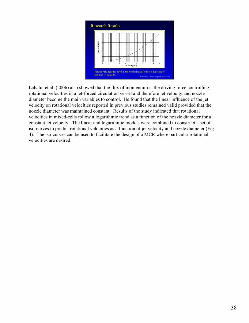
Labatut et al. (2006) also showed that the flux of momentum is the driving force controlling rotational velocities in a jet-forced circulation vessel and therefore jet velocity and nozzle diameter become the main variables to control. He found that the linear influence of the jet velocity on rotational velocities reported in previous studies remained valid provided that the nozzle diameter was maintained constant. Results of the study indicated that rotational velocities in mixed-cells follow a logarithmic trend as a function of the nozzle diameter for a constant jet velocity. The linear and logarithmic models were combined to construct a set of iso-curves to predict rotational velocities as a function of jet velocity and nozzle diameter (Fig. 4). The iso-curves can be used to facilitate the design of a MCR where particular rotational velocities are desired
38
Recirculating Aquaculture Systems Short Course
Research ResultsResearch Results
Piezometric head required in the vertical manifolds as a function of the inlet jet velocity.
Labatut et al. (2006) also showed that the flux of momentum is the driving force controlling rotational velocities in a jet-forced circulation vessel and therefore jet velocity and nozzle diameter become the main variables to control. He found that the linear influence of the jet velocity on rotational velocities reported in previous studies remained valid provided that the nozzle diameter was maintained constant. Results of the study indicated that rotational velocities in mixed-cells follow a logarithmic trend as a function of the nozzle diameter for a constant jet velocity. The linear and logarithmic models were combined to construct a set of iso-curves to predict rotational velocities as a function of jet velocity and nozzle diameter (Fig. 4). The iso-curves can be used to facilitate the design of a MCR where particular rotational velocities are desired

39
Recirculating Aquaculture Systems Short Course
Research Application Research Application -- DesignDesign
Zero-exchange Mixed-cell Raceway• 0.5 exchange rate / hr (250 gpm)• 15% (35 gpm) center drains
Optimal Tank Rotational Velocity• Average 10 cm/sec• Discharge Jet Velocity = 4 m/s• Pressure Head = 1 m
In a zero-exchange system, ammonia-nitrogen is removed via the growth of heterotrophic bacteria, stocking densities are low (5 to 10 kg /m3) and oxygen requirements are modest, so high tank exchange rates through biofilters and oxygenators are not necessary. At an exchange rate of approximately 0.5 tank volume/hr, a flow rate of only 0.74 m3/min (250 gpm) is required for the raceway in this example. This was accomplished using two 0.95 kW (1 hp) pumps which removed water at the two ends of the raceway and injected it into a 7.5 cm (3 in) manifold that circled the top of the raceway. Water was withdrawn either from a 5 cm (2 in) PVC pipe inlet located approximately 25 cm below the surface at one end or an end sidewall discharge drain at the other. Approximately 15% of the flow 0.13 m3/min (35 gpm) was from the three bottom drains, using a smaller 0.375 kW (1/2 hp) submersible pump in the sump drain.
Little is know about the optimal tank rotational velocities for marine shrimp. A mean tank velocity of 10 cm/s was chosen to insure adequate rotational velocities to move waste particles and uneaten food to the center drains,. From Fig. 3, the required discharge jet velocity for a tank mean rotational velocity of 10 cm/s is approximately 4 m/s. The required piezometric head to achieve this jet velocity is computed from the equation described by Brater and King (1976):
40
Recirculating Aquaculture Systems Short Course
Research ResultsResearch Results
0.50 tank exchanges per hour0.74 m3/min (250 gpm)10 mm discharge orifice1.00 m pressure head15% from center drain
1.5 kW Pumps (2 Hp)
#2 #3#1
-2.5 -2.0 -1.5 -1.0 -0.5 0.0 0.5 1.0 1.5 2.0 2.5
-2.5
-2.0
-1.5
-1.0
-0.5
0.0
0.5
1.0
1.5
2.0
2.5 2 cm/sec4 6 8 10 12 14 16 18 20 22 24
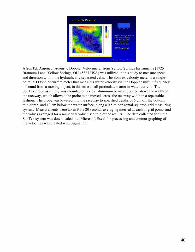
A SonTek Argonaut Acoustic Doppler Velocimeter from Yellow Springs Instruments (1725 Brannum Lane, Yellow Springs, OH 45387 USA) was utilized in this study to measure speed and direction within the hydraulically separated cells. The SonTek velocity meter is a single-point, 3D Doppler current meter that measures water velocity via the Doppler shift in frequency of sound from a moving object, in this case small particulate matter in water current. The SonTek probe assembly was mounted on a rigid aluminum beam supported above the width of the raceway, which allowed the probe to be moved across the raceway width in a repeatable fashion. The probe was lowered into the raceway to specified depths of 5 cm off the bottom, mid-depth, and 10 cm below the water surface, along a 0.5 m horizontal-squared-grid measuring system. Measurements were taken for a 20 seconds averaging interval at each of grid points and the values averaged for a numerical value used to plot the results. The data collected form the SonTek system was downloaded into Microsoft Excel for processing and contour graphing of the velocities was created with Sigma Plot.

41
Recirculating Aquaculture Systems Short Course
Research ResultsResearch ResultsMixed Cell Hydrodynamics
13.1
16.214.4
11.1
8.2
5.6
3.2
0.4
0
4
8
12
16
20
Center
0.0-0.5 m
0.5-1.0 m
1.0-1.5 m
1.5-2.0 m
2.0-2.5 m
2.5-2.7 m
corner
Vel
ocity
(cm
/s)
.
The above Figure shows the contour plot for cell #3 (end cell) at velocity intervals of 5 cm/sec, approximately 5 cm off the bottom. The pressure head was approximately 1.00 m gauge (1.5 psi). As can be seen in this figure, relatively high scouring velocities are found at the outside perimeter of the cell (20 to 24 cm/sec), lower velocities near the center (10 to 6 cm/sec) and very low velocities at the center of the cell. The velocity profiles shown in Figure 6 were created by averaging the velocities at each grid point in an annular ring 0.5 m wide starting at the center at each of the three depths. This graph shows the almost linear velocity profile as a function of distance from the center drain and significant cleaning velocities in the corners of the cell. The velocities in the z-direction were very small, just above the drain values of -2.2 to 2.8 cm/s was measured. The mean tank rotational velocity was estimated from the average of all measurements taken as 10.5 cm/s, consistent with both the initial assumption and Fig. 4.

42
Recirculating Aquaculture Systems Short Course
Tank Access & Tank EnclosuresTank Access & Tank EnclosuresWas tank access designed into the tank layout?

43
Recirculating Aquaculture Systems Short Course
Tank Design ExampleTank Design ExampleProduction Goal: 1.0 million lb/yr(454 mton/yr)
The production goal of this design example is 1 million lb per year.

44
Recirculating Aquaculture Systems Short Course
Design AssumptionsDesign Assumptions
Assuming:• Mean feeding rate: rfeed = 1.2% BW/day
• Feed conversion rate: FCR = 1.3 kg feed/kg fish produced
• Culture Density : 80 kg fish/m3
(these rates are an average over entire year)
For any design, some assumptions need to me made, hopefully based either on actual experience or reputable research.

45
Recirculating Aquaculture Systems Short Course
System Biomass EstimationSystem Biomass Estimation
Estimate of system’s average feeding biomass :
( )
systeminfishkgday
yrfeedkg
daysysteminfishkgproducedfishkg
feedkgyr
producedkg
rFCRproductionannualBiomass
feedsystem
600,1293652.1
100
3.1000,454
)(
=
⋅⋅
⋅
⋅=
⋅=
Based on the design goals, the total biomass in the production system can be estimated from the Feed Conversion Rate (FCR) and the feed rate (rfeed).

46
Recirculating Aquaculture Systems Short Course
Total Oxygen RequirementsTotal Oxygen Requirements• Estimate the oxygen demand of system’s feeding fish:
• where:• RDO = average DO consumption Rate
= kg DO consumed by fish per day)
• aDO = average DO consumption proportionality constant= kg DO consumed per 1 kg feed
Ranges from 0.4 to 1.0 kg O2/kg feed – cold water to warm water
dayconsumedDOkgfeedkg
DOkgdayfishkg
feedkgfishkg
arbiomassR DOfeedsystemDO
/ 1166 1
75.0 100
2.1600,129
=
⋅⋅
⋅=
⋅⋅=
To estimate the oxygen demand of the system, the average dissolved oxygen consumed per kg of feed is used (aDO) and multiplied by the feed rate (rfeed) and the total biomass of the system (biomasssystem).

47
Recirculating Aquaculture Systems Short Course
Total Flow Requirement Total Flow Requirement –– Oxygen LoadOxygen Load
• Estimate water flow (Q) required for fish’s O2 demand:• Assuming culture tank:
• DOinlet = 20 mg/L• DOeffluent= 6 mg/L (@ steady state)
( )
( )min)/280,15(min/ 840,57
min 1440 620 10 1166
1
6
galL
daymg
Lkg
mgday
DOkg
DODOrQ
effluentinletDOFlow
=
⋅−
⋅⋅=
−⋅=
In this example, the change in DO across the culture tank is 7 mg/L, which is conservative for a well designed recirc system for coldwater fish. A more aggressive, but usually achievable, inlet DO would be 20-22 mg/L, which would produce an available DO across the culture tank of about 13 mg/L. In practice, this is about the maximum DO loading that can be safely managed with coldwater systems. First, 22 mg/L is near the effective limit of LHO technology to add DO in coldwater applications.

48
Recirculating Aquaculture Systems Short Course
Total Tank Volume RequirementsTotal Tank Volume Requirements
Assume an average fish density across all culture tanks in the system:• culture density = 80 kg fish/m3
)000,428( 620,160
1600,129
3
3
galmfishkg
mfishkg
DensityCultureBiomassVolumeCulture system
=
⋅=
⋅=
A culture density of 80 kg/m3 is considered the average density found within the entire system. The maximum density in a culture tank might be 120 kg/m3 while other tanks in the same facility might be as low as 30 kg/m3. In reality, unless batch production is used in the entire facility, the average culture density found in facility will be considerably less than the maximum density that could be supported in a given culture tank. Also, because densities can vary between tanks, some tanks would receive more water than others to supply the extra oxygen needed to support these fish.

49
Recirculating Aquaculture Systems Short Course
Check Culture Tank Exchange RateCheck Culture Tank Exchange Rate
In general, a culture tank exchange every 30-60 minutes provides good flushing of waste metabolites while maintaining hydraulics within
circular culture tanks
min28 84.57
min620,1 33
tan
=
⋅=m
mEXCH k
In general, a culture tank exchange every 30-60 minutes provides good flushing of waste metabolites while maintaining hydraulics within circular culture tanks (when the tank inlet and outlet structures are designed properly.

50
Recirculating Aquaculture Systems Short Course
Number of Tanks RequiredNumber of Tanks Required
Assuming 9 m (30 ft) dia tanks• water depth
• 2.3 m• 7.5 ft
• culture volume per tank• 150 m3
• 40,000 gal
• 10-11 culture tanks required
Assuming 15 m (50 ft) dia tanks• water depth
• 3.7 m• 12 ft
• culture volume per tank• 670 m3
• 177,000 gal
• 2-3 culture tanks required
If future expansion of the farm is expected to achieve 2-4 times more production, then maybe choose 50 ft diameter tanks. Otherwise, choosing 30 ft tanks would be a okay choice to achieve 1 million lb maximum production.
To use tanks as large as 50 ft diameter requires knowledge of tank inlet and outlet structure designs to ensure that good mixing is achieved and that safe rotational velocities can be maintained for fish health and for flushing settleable solids. If water must rotate about the axis of a culture tank once in 60-90 seconds to achieve good solids flushing, then the fish swimming in larger (e.g., 50 ft tanks) must be capable of swimming at these speeds. Water velocities are greatest near the tank’s outside wall where the perimeter distance is πD. Therefore, in a 50 ft tank fish swimming with the current near the tank’s outside wall would be swimming between 1.7-2.6 ft/s. Maximum safe swimming velocities for salmonids are considered to be between 1-2 body length per second. However, in ‘Cornell-type’ dual-drain tanks the water velocity decreases as the fish swim closer to the center of the tank, which allows fish to select what velocity they want to swim against by moving to different locations in the culture tank.

51
Recirculating Aquaculture Systems Short Course
Design SummaryDesign Summary
Ten Production Tanks• Diameter
• 9.14 m ( 30 ft )
• Water depth• 2.3 m (7.5 ft)
• Culture volume per tank• 150 m3 (40,000 gal)
• Flow Rate• 5,000 Lpm (1,320gpm)
• Biomass Density• 86 kg/m3 (0.72 lbs/gal)

52
Recirculating Aquaculture Systems Short Course
DualDual--Drain Tanks DesignDrain Tanks Design
Bottom Flow a) 400 Lpm (106 gpm)b) 750 Lpm (198 gpm)c) 500 to 750 lpm (132 to 200 gpm)
"Rule of Thumb“
Choose the Center Drain Flow as the largest of: a) 0.15 gpm/ft2 (6 Lpm/m2) of floor,b) HRT center drain < 200 minutes, orc) 10 to 15% of total tank flow rate.

53
Recirculating Aquaculture Systems Short Course
DualDual--Drain Tanks DesignDrain Tanks Design
Side Discharge Flow 4,800 Lpm (1120 gpm)

54
Recirculating Aquaculture Systems Short Course
Questions?Questions?