d dryer dc desiccant - conairpurpose of the user guide this user guide describes the conair d series...
TRANSCRIPT

D Carousel Dryer - DCModels 15, 25, 50, 75, and 100 with DC Controls
Corporate Office: 412.312.6000 l Instant Access 24/7 (Parts and Service): 800.458.1960 l Parts and Service: 814.437.6861
U S E R G U I D E
UGD022/0304
www.conairnet.com
INTRODUCTION • Purpose of the User Guide • How the guide is organized • Your responsibilities as a user • ATTENTION:
Read this so no one gets hurt • How to use the lockout device • DESCRIPTION • What is the D Carousel Dryer? •
Typical applications • How it works • Specifications: D Dryer • INSTALLATION • Unpacking the boxes • Preparing for
installation • Mounting the dryer and hopper on a Processing Machine • Positioning the dryer on the floor; Mounting the
hopper on the throat • Mounting the dryer on the floor stand; Hopper on the throat • Mounting the dryer and hopper on
the mobile floor stand • Connecting the main power • Checking for proper air flow • Connecting the air hoses
•Connecting water hoses • Connecting the RTD probe • Mounting a loader on the hopper • OPERATION • How it works
• The DC dryer control panel • D dryer DC control functions • Control Function Description • To start drying • To stop
drying • Using the auto start countdown function • Setting high and low setpoint limits • MAINTENANCE
Please record your equipment’smodel and serial number(s) andthe date you received it in thespaces provided.
It’s a good idea to record the model and serial number(s) of your equipment andthe date you received it in the User Guide. Our service department uses this infor-mation, along with the manual number, to provide help for the specific equipmentyou installed.
Please keep this User Guide and all manuals, engineering prints and parts liststogether for documentation of your equipment.
Date:
Manual Number: UGD022/0304
Serial Number(s):
Model Number(s):
DISCLAIMER: The Conair Group, Inc., shall not be liable for errors contained in this User Guide orfor incidental, consequential damages in connection with the furnishing, performance or use ofthis information. Conair makes no warranty of any kind with regard to this information, including,but not limited to the implied warranties of merchantability and fitness for a particular purpose.
Copy r i gh t 2004 l The Cona i r G roup l A l l r i gh t s r ese r ved

Tab le o f Conten ts
1-1 I n t r oduc t i on
Purpose of the User Guide . . . . . . . . . . . . . . . . . . . . . . . . . . . . . . 1-2
How the guide is organized . . . . . . . . . . . . . . . . . . . . . . . . . . . . . 1-2
Your responsibilities as a user . . . . . . . . . . . . . . . . . . . . . . . . . . . 1-3
ATTENTION: Read this so no one gets hurt . . . . . . . . . . . . . . . . . . 1-4
How to use the lockout device . . . . . . . . . . . . . . . . . . . . . . . . . . . 1-5
2-1 Desc r i p t i onWhat is the D Carousel Dryer?. . . . . . . . . . . . . . . . . . . . . . . . . . . .2-2
Typical applications . . . . . . . . . . . . . . . . . . . . . . . . . . . . . . . . . . .2-2
How it works . . . . . . . . . . . . . . . . . . . . . . . . . . . . . . . . . . . . . . . .2-4
Specifications: D Dryer . . . . . . . . . . . . . . . . . . . . . . . . . . . . . . . . 2-6
3-1 I n s t a l l a t i onUnpacking the boxes . . . . . . . . . . . . . . . . . . . . . . . . . . . . . . . . . 3-2
Preparing for installation . . . . . . . . . . . . . . . . . . . . . . . . . . . . . . . 3-4
Mounting the dryer and hopper on a Processing Machine . . . . . . . 3-6
Positioning the dryer on the floor; Mounting the hopper
on the throat . . . . . . . . . . . . . . . . . . . . . . . . . . . . . . . . . . . 3-8
Mounting the hopper . . . . . . . . . . . . . . . . . . . . . . . . . . . . . . . . . . 3-9
Positioning the dryer on the floor . . . . . . . . . . . . . . . . . . . . . . . . . 3-9
Mounting the dryer on the floor stand; Hopper on the throat. . . . . 3-10
Mounting the dryer and hopper on the mobile floor stand . . . . . . 3-10
Connecting the main power . . . . . . . . . . . . . . . . . . . . . . . . . . . . 3-10
Checking for proper air flow. . . . . . . . . . . . . . . . . . . . . . . . . . . . 3-12Tab le o f Con ten t s l i
Connecting the air hoses . . . . . . . . . . . . . . . . . . . . . . . . . . . . . . 3-15
Connecting water hoses. . . . . . . . . . . . . . . . . . . . . . . . . . . . . . . 3-15
Connecting the RTD probe . . . . . . . . . . . . . . . . . . . . . . . . . . . . . 3-16
Mounting a loader on the hopper . . . . . . . . . . . . . . . . . . . . . . . . 3-17
Testing the installation . . . . . . . . . . . . . . . . . . . . . . . . . . . . . . . . 3-17
4-1 Opera t i on
The DC dryer control panel . . . . . . . . . . . . . . . . . . . . . . . . . . . . . 4-2
D dryer DC control functions . . . . . . . . . . . . . . . . . . . . . . . . . . . . 4-3
Control function flow chart . . . . . . . . . . . . . . . . . . . . . . . . . . . . . . 4-3
Control function descriptions . . . . . . . . . . . . . . . . . . . . . . . . . . . . 4-6
To start drying . . . . . . . . . . . . . . . . . . . . . . . . . . . . . . . . . . . . . . 4-20
To stop drying . . . . . . . . . . . . . . . . . . . . . . . . . . . . . . . . . . . . . . 4-20
5-1 Main tenancePreventative maintenance checklist . . . . . . . . . . . . . . . . . . . . . . . 5-2
Cleaning the hopper . . . . . . . . . . . . . . . . . . . . . . . . . . . . . . . . . . 5-3
Cleaning the process filter . . . . . . . . . . . . . . . . . . . . . . . . . . . . . . 5-4
Cleaning the regeneration filter . . . . . . . . . . . . . . . . . . . . . . . . . . 5-4
Cleaning the aftercooler coils . . . . . . . . . . . . . . . . . . . . . . . . . . . . 5-5
Cleaning the precooler coils . . . . . . . . . . . . . . . . . . . . . . . . . . . . . 5-5
Inspecting hoses and gaskets . . . . . . . . . . . . . . . . . . . . . . . . . . . 5-5
i i l Tab l e o f Con ten t s
6-1 Troub leshoo t i ngBefore beginning . . . . . . . . . . . . . . . . . . . . . . . . . . . . . . . . . . . . . 6-2
A few words of caution . . . . . . . . . . . . . . . . . . . . . . . . . . . . . . . 6-3
DIAGNOSTICS
How to identify the cause of a problem . . . . . . . . . . . . . . . . . . . . 6-4
Shut down alarms . . . . . . . . . . . . . . . . . . . . . . . . . . . . . . . . . . . 6-5
Passive alarms . . . . . . . . . . . . . . . . . . . . . . . . . . . . . . . . . . . . . 6-10
REPAIR
Replacing fuses. . . . . . . . . . . . . . . . . . . . . . . . . . . . . . . . . . . . . 6-11
Checking heater solid state relays . . . . . . . . . . . . . . . . . . . . . . . 6-12
Checking or replacing temperature sensors. . . . . . . . . . . . . . . . . 6-13
Adjusting the limit switch. . . . . . . . . . . . . . . . . . . . . . . . . . . . . . 6-14
Replacing the heaters . . . . . . . . . . . . . . . . . . . . . . . . . . . . . . . . 6-15
Replacing the desiccant tanks . . . . . . . . . . . . . . . . . . . . . . . . . . 6-19
Refilling the desiccant tanks. . . . . . . . . . . . . . . . . . . . . . . . . . . . 6-20
A A ppend i xWe’re Here to Help . . . . . . . . . . . . . . . . . . . . . . . . . . . . . . . . . . . A-1
How to Contact Customer Service . . . . . . . . . . . . . . . . . . . . . . . . A-1
Before You Call... . . . . . . . . . . . . . . . . . . . . . . . . . . . . . . . . . . . . A-1
Equipment Guarantee . . . . . . . . . . . . . . . . . . . . . . . . . . . . . . . . . A-2
Performance Warranty . . . . . . . . . . . . . . . . . . . . . . . . . . . . . . . . . A-2
B A ppend i xMounting the Dryer on a Floor Stand . . . . . . . . . . . . . . . . . . . . . . B-1
Mounting the Dryer and Hopper on a Mobile
Floor stand . . . . . . . . . . . . . . . . . . . . . . . . . . . . . . . . . . . . B-2
Tab le o f Con ten t s l i i i

C A ppend i xInstalling an aftercooler (optional) . . . . . . . . . . . . . . . . . . . . . . . . C-1
Cleaning the aftercooler . . . . . . . . . . . . . . . . . . . . . . . . . . . . . . . C-3
D AppendixInstalling a precooler (optional) . . . . . . . . . . . . . . . . . . . . . . . . . . D-1
Cleaning the precooler . . . . . . . . . . . . . . . . . . . . . . . . . . . . . . . . D-3
i v l Tab l e o f Con ten t s

I n t roduc t ion
Purpose o f t he use r gu ide . . . . . . . . . . . . . 1 -2
Ho w the gu ide i s o rgan i zed . . . . . . . . . . . . 1 -2
You r r espons ib i l i t i e s as a use r . . . . . . . . . . 1 -3
ATTENT ION :Read t h i s so no one ge t s hu r t . . . . . . . . 1 -4
Ho w to use t he l ockou t dev i ce . . . . . . . . . . 1 -5
S E C T I O N
1
I n t r oduc t i on l 1-1
1In
trodu
ction
✐
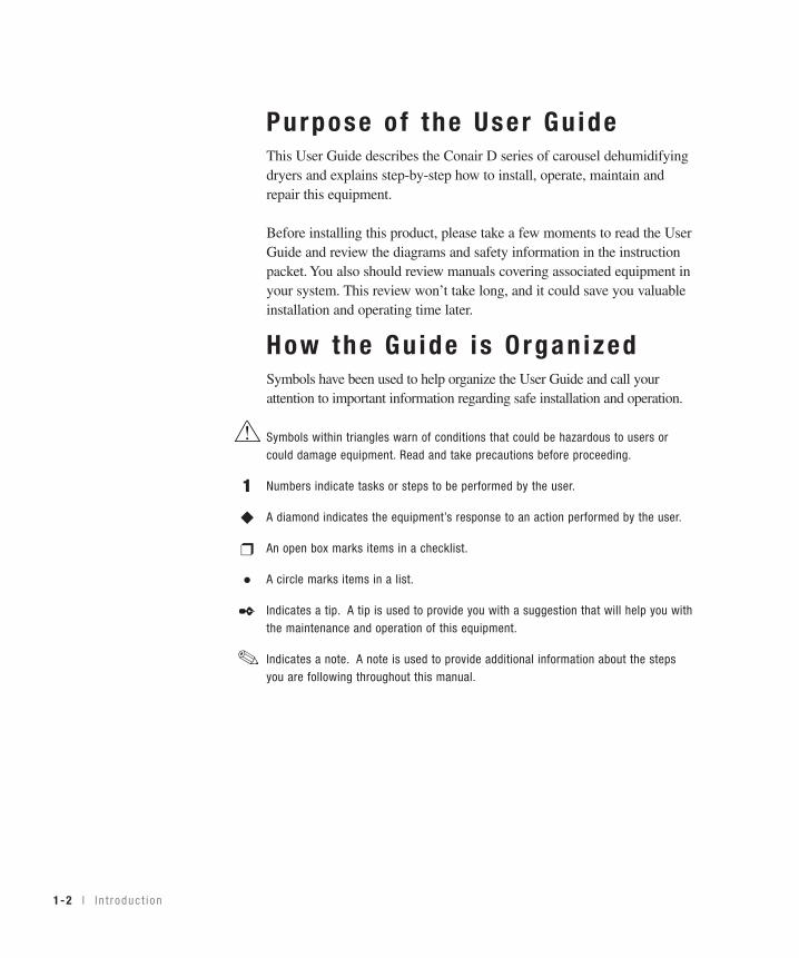
Purpose o f the User Gu ideThis User Guide describes the Conair D series of carousel dehumidifyingdryers and explains step-by-step how to install, operate, maintain andrepair this equipment.
Before installing this product, please take a few moments to read the UserGuide and review the diagrams and safety information in the instructionpacket. You also should review manuals covering associated equipment inyour system. This review won’t take long, and it could save you valuableinstallation and operating time later.
How the Gu ide i s O rgan izedSymbols have been used to help organize the User Guide and call yourattention to important information regarding safe installation and operation.
Symbols within triangles warn of conditions that could be hazardous to users orcould damage equipment. Read and take precautions before proceeding.
Numbers indicate tasks or steps to be performed by the user.
A diamond indicates the equipment’s response to an action performed by the user.
An open box marks items in a checklist.
A circle marks items in a list.
Indicates a tip. A tip is used to provide you with a suggestion that will help you withthe maintenance and operation of this equipment.
Indicates a note. A note is used to provide additional information about the stepsyou are following throughout this manual.
1
◆
❒
•✒
1-2 l I n t r oduc t i on

Your Respons ib i l i t y as a UserYou must be familiar with all safety procedures concerning installation, opera-tion and maintenance of this equipment. Responsible safety procedures include:
• Thorough review of this User Guide, paying particular attention to hazard warnings, appendices and related diagrams.
• Thorough review of the equipment itself, with careful attention to voltage sources, intended use and warning labels.
• Thorough review of instruction manuals for associated equipment.• Step-by-step adherence to instructions outlined in this User Guide.
I n t r oduc t i on l 1-3
1In
trodu
ction

1-4 l I n t r oduc t i on
ATTENT ION :Read th is so no one ge ts hur tWe design equipment with the user’s safety in mind. You can avoid the potentialhazards identified on this machine by following the procedures outlined below andelsewhere in the User Guide.
WARNING: Improper ins ta l l a t ion , opera t ion , o rser v ic ing may resu l t i n equ ipment damage o rpersona l in ju r y.
This equipment should be installed, adjusted, and serviced by qualifiedtechnical personnel who are familiar with the construction, operation,and potential hazards of this type of machine.
All wiring, disconnects, and fuses should be installed by qualified elec-trical technicians in accordance with electrical codes in your region.Always maintain a safe ground. Do not operate the equipment at powerlevels other than what is specified on the machine serial tag and dataplate.
WARNING: Vo l tage hazard
This equipment is powered by three-phase alternating current,as specified on the machine serial tag and data plate.
A properly sized conductive ground wire from the incoming power supply must be connected to the chassis ground terminal inside theelectrical enclosure. Improper grounding can result in severe personalinjury and erratic machine operation.
Always disconnect and lock out the incoming main power source beforeopening the electrical enclosure or performing non-standard operatingprocedures, such as routine maintenance. Only qualified personnelshould perform troubleshooting procedures that require access to theelectrical enclosure while power is on.

I n t r oduc t i on l 1-5
How to Use the Lockout Dev iceCAUTION: Before performing maintenance or repairs on this product, you should disconnect and lockout electri-cal power sources to prevent injury from unexpected energization or start-up. A lockable device has been provid-ed to isolate this product from potentially hazardous electricity.
Lockout is the preferred method of isolating machines or equipment from energy sources. Your Conair productis equipped with the lockout device pictured below. To use the lockout device:
11 Stop or turn off the equipment.
22 Isolate the equipment from the electric power. Turn the rotarydisconnect switch to the OFF, or “O” position.
33 Secure the device with an assigned lock or tag. Insert a lock or tag in the holes to prevent movement.
44 The equipment is now locked out.
WARNING: Before removing lockout devices and returning switches tothe ON position, make sure that all personnel are clear of the machine,tools have been removed, and all safety guards reinstalled.
To turn the rotary disconnect back to the ON position:
11 Remove the lock or tag.
22 Turn the rotary disconnect switch to the ON or “I” position.
1In
trodu
ction

1-6 l I n t r oduc t i on

Descr ip t ion
Wha t i s t he D ca rouse l d r ye r? . . . . . . . . . . 2 -2
Typ i ca l a pp l i ca t i ons . . . . . . . . . . . . . . . . . 2 -2
Ho w i t wo rks . . . . . . . . . . . . . . . . . . . . . . 2 -4
Spec i f i ca t i ons : D d r ye r . . . . . . . . . . . . . . . 2 -6
S E C T I O N
22
Descrip
tion
D esc r i p t i on l 2-1

What i s the D Carouse l Dr yer?The D carousel dehumidifying dryer produces hot, low-dew point air that removesmoisture from hygroscopic plastics. The dryer pulls warm, moist air from a dryinghopper and pumps it through dehumidifying desiccant. The dryer then heats the airto the drying temperature you selected and circulates it through the material in thehopper.
The dryer’s three-tank, closed-loop design ensures a continuous supply of hot,dehumidified air while preventing contamination from moisture in the plant.
Typ ica l App l i ca t ions
2-2 l Desc r i p t i on
The D dryer can bemounted beside the hopper on the throat of aprocessing machine usingthe optional diving board support frame, or positioned on the floornear the machine using thestandard casters. Twomobile floor stand designsare also available.
Dryer on a floor stand; hopper on thethroat.
Dryer and hopper on the processingmachine throat using the optional support frame.
Dryer on the floor; hopper on the throat.

Desc r i p t i on l 2-3
2D
escription
Typ ica l App l i ca t ions (cont inued)
The D carousel dryer can be used successfully in applications that require:• A contamination-free drying environment.• Drying temperatures within the ranges shown in the following table:
Model Drying Temperature Range
Low temperature (with precooler)* 100° - 150°F (38° - 66°C)
Standard 150° - 250°F (66° - 121°C)
High heat (with aftercooler) 150° - 375°F (66° - 191°C)
Low-high (with aftercooler & precooler)* 100° - 375°F (38° - 191°C)
• Throughput rates of 15 to 100 lbs (6.8 to 37.3 kg) per hour (some materialscan be run at a higher rate).
• Dew points of -40°F (-40°C).
If you are drying material at temperatures over 250°F (121°C), you will need thehigh-temperature package that includes an aftercooler. An aftercooler is standardequipment on the High heat and Low-high models.
*WARNING: The precooler mustNOT be installed in the processline for temperature setpointsabove 150°F (65.5°C). The pre-cooler hosing will absorb toomuch heat and will result in poorprocess temperature control.
If you disregard this warning youwill get a loop break alarm.

How I t WorksThe D carousel dryer achieves continuous, closed loop drying by passing air simul-taneously through two heaters and three tanks of molecular sieve desiccant.
THE PROCESS (DRYING) CYCLE
The process blower pulls moist air from the top of the drying hopper. The air pass-es through the process filter (and optional aftercooler, if installed) into the dryer’sdesiccant tank, where moisture is removed. The now dry air moves through theprocess heater, where it is heated to the drying temperature selected by the opera-tor. The hot, dry air is delivered to the hopper (after it passes through the optionalprecooler, if installed) where a spreader cone evenly distributes the air through thematerial.
The Cooling CycleA regenerated desiccant tank must be cooled before it is moved back into theprocess cycle. The process blower pushes a small amount of air through the regen-erated desiccant tank. The cooling air then passes through the optional aftercooler,if installed, and repeats the circuit.
The Regeneration CycleThe regeneration blower pulls air through the regeneration filter into the dryer’sregeneration heater. The air is heated to 425°F (218°C) before it is pushed into the“wet” desiccant tank. The hot air purges moisture from the desiccant. The moist airis blown out the exhaust at the back of the dryer.
2-4 l Desc r i p t i on

2D
escription
How I t Works (cont inued)
REGENERATIONAIR FILTER
DESICCANTTANKS
BEDPLATE
REGENERATIONBLOWER
REGENERATIONHEATER
HIGH TEMP SHUTOFF
REGENERATIONRTD
HOPPER
PROCESSBLOWER
RETURNAIR
FILTER
3 ALARM HORN
RETURN AIRRTD
PROCESSRTD
1 PRECOOLER
HIGH TEMP SHUTOFF
PROCESSHEATER BOX
4 ALARM LIGHT
34
2 AFTERCOOLER
1
DRYER OPTIONS
PROCESS
COOLING
REGENERATION
2
PROCESSPROTECTION
RTD
Desc r i p t i on l 2-5

2-6 l Desc r i p t i on
Spec i f i ca t ions : D Carouse l DEHUMIDIFYING DRYERSD Small Series Carousel Dryers
MODEL D15 D25 D50 D75 D100Performance characteristics (with full hopper)
Air flow {SCFM}* 12 20 35 50 80Air flow {ACFM @ 250°}* 16 27 47 67 107Drying temperature All models 100 - 375° F {38 - 191° C} with optionsDew point All models -40° F {-40° C}
Dimensions inches {cm}A - Height 35.5 {90.2} 35.5 {90.2} 35.5 {90.2} 42.1 {107} 42.1 {107}B - Overall width 17.3 {43.9} 17.3 {43.9} 17.3 {43.9} 22.0 {55.9} 22.0 {55.9}C - Control width 15.7 {39.9} 15.7 {39.9} 15.7 {39.9} 15.7 {39.9} 15.7 {39.9}D - Depth 24.8 {63.0} 24.8 {63.0} 24.8 {63.0} 30.3 {77.0} 30.3 {77.0} Control depth 7.3 {18.5} 7.3 {18.5} 7.3 {18.5} 7.3 {18.5} 7.3 {18.5}Outlet/inlet tube size OD 2.5 2.5 2.5 2.5 2.5
Weight lbs {kg}Installed 225 {102} 225 {102} 240 {109} 310 {141} 340 {155}
Voltage † Total Amps208 V/3 phase/60 Hz 12.2 12.2 17.7 25.5 NA240 V/3 phase/60 Hz 10.5 10.5 15.5 22.3 33.1400 V/3 phase/50 Hz 6.5 6.5 9.3 13.2 18.1
480 V/3 phase/60 Hz 5.3 5.3 7.8 11.2 16.7575 V/3 phase/60 Hz 4.4 4.4 6.7 9.2 13.9
Total kilowatts kw {BTU/min} 2.2 {125} 2.5 {142} 3.4 {193} 6.1 {347} 9.0 {512}Water requirements {for optional aftercooler or precooler}Recommended temperature* 45° - 85° F 45° - 85° F Water flow gal./min. {liters/min.} 1 {3.8} 2 {7.6}Water connections NPT 1/2 inch NPT
SPECIFICATION NOTES:* SCFM stands for standard cubic feet per minute, referenced to a pre-specified pressure, temperature and relative humidity. In most
cases, SCFM is referenced to 14.7 PSIA 68° F and 0% relative humidity. ACFM stands for actual cubic feet per minute, and must besupplied with a temperature reference, due to the change in air density with temperature. Because dryers operate at a relatively lowpressure the effects on air density are negligible.
† Dryers running at 50 HZ will have 17% less airflow, and a 17% reduction in material throughput.
Specifications may change without notice. Consult a Conair representative for the most current information.
D
A
CB
Desc r i p t i on l 2-7
2D
escription
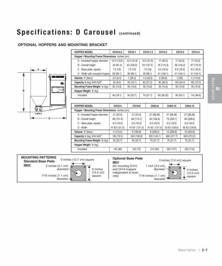
Spec i f i ca t ions : D Carouse l (cont inued)
7/16 inches {1.1 cm}diameter
4 inches{10.2 cm}square
1 inch {2.5 cm}diameter
3 inches {7.6 cm} square
6 inches{15.2 cm}square7/16 inches {1.1 cm}
diameter
5 inches {12.7 cm} square
2 inches {5.1 cm}diameter
Standard Base Plate IB02
Optional Base Plate IB01 (for mounting CH10 and CH14 hoppers independent of dryeronly)
▲
▲▲
▲
▲
▲
▲
▲
▲
▲OPTIONAL HOPPERS AND MOUNTING BRACKET
MOUNTING PATTERNS
▲
▲
HOPPER MODEL CH10-0.5 CH10-1 CH10-1.5 CH14-2 CH14-3 CH14-4
Hopper / Mounting Frame Dimensions inches {cm}
A - Insulated hopper diameter 12.5 {13.8} 12.5 {31.8} 12.5 {31.8} 17 {43.2} 17 {43.2} 17 {43.2}
B - Overall height 32 {81.3} 43 {109.2} 54 {137.2} 45 {114.3} 56 {142.2} 67 {170.2}
C - Base plate, square 7.5 {19} 7.5 {19} 7.5 {19} 6.5 {16.5} 6.5 {16.5} 6.5 {16.5}
D - Width with insulated hopper 39 {99.1} 39 {99.1} 39 {99.1} 41 {104.1} 41 {104.1} 41 {104.1}
Volume ft3 {liters} 0.5 {9.4} 1 {28.3} 1.5 {42.5} 2 {56.6} 3 {85} 4 {113.2}
Capacity lb {kg} @40 lb/ft3 20 {9.0} 40 {18.1} 60 {27.2} 80 {36.3} 120 {54.4} 160 {72.5}
Mounting Frame Weight lb {kg} 30 {13.6} 30 {13.6} 30 {13.6} 35 {15.9} 35 {15.9} 35 {15.9}
Hopper Weight lb {kg}
Insulated 40 {18.1} 50 {22.7} 70 {31.7} 80 {36.32} 95 {43.1} 110 {48.9}
HOPPER MODEL CH18-4 CH18-6 CH24-8 CH24-12 CH24-15
Hopper / Mounting Frame Dimensions inches {cm}
A - Insulated hopper diameter 21 {53.3} 21 {53.3} 27 {68.58} 27 {68.58} 27 {68.58}
B - Overall height 48 {121.9} 68 {172.7} 64 {162.6} 79 {200.7} 90 {228.6}
C - Base plate, square 6.5 {16.5} 6.5 {16.5} 6.5 {16.5} 6.5 {16.5} 6.5 {16.5}
D - Width 47.63 {121.0} 47.63 {121.0} 47.63 {121.0} 50.63 {128.6} 50.63 {128.6}
Volume ft3 {liters} 4 {113.3} 6 {169.9} 8 {226.5} 12 {339.8} 15 {424.8}
Capacity lb {kg} @40 lb/ft3 160 {72.5} 240 {108.9} 320 {145.1} 480 {217.7} 600 {272.2}
Mounting Frame Weight lb {kg} 50 {22.7} 50 {22.7} 70 {31.7} 70 {31.7} 70 {31.7}
Hopper Weight lb {kg}
Insulated 145 {66} 165 {75} 210 {95} 235 {107} 255 {116}
D
B
A
C

2-8 l Desc r i p t i on

I ns ta l l a t ionUnpack ing t he boxes . . . . . . . . . . . . . . . . . 3 -2
P repa r i ng f o r i n s t a l l a t i on . . . . . . . . . . . . . . 3 -4
Moun t i ng t he d r ye r and hoppe r on a p rocess ing mach ine . . . . . . . . . . . . . . 3 -6
Pos i t i on i ng t he d r ye r on t he f l oo r ; moun t i ng t he hoppe r on t he t h roa t . . . . . 3 -8
Moun t i ng t he hoppe r . . . . . . . . . . . . . . . . . 3 -9
Pos i t i on i ng t he d r ye r on t he f l oo r . . . . . . . . 3 -9
Moun t i ng t he d r ye r on t he f l oo r s t and ; hoppe r on t he t h roa t . . . . . . . . . . . . . 3 -10
Moun t i ng t he d r ye r and hoppe r on t he mob i l ef l oo r s t and . . . . . . . . . . . . . . . . . . . 3 -10
Connec t i ng t he ma in po wer . . . . . . . . . . . 3 -10
Check ing f o r p rope r a i r f l o w . . . . . . . . . . . 3 -12
Connec t i ng t he a i r hoses . . . . . . . . . . . . . 3 -15
Connec t i ng t he wa te r hoses . . . . . . . . . . . 3 -15
Connec t i ng t he RTD p robe . . . . . . . . . . . . 3 -16
Moun t i ng a l oade r on t he hoppe r . . . . . . . . 3 -17
Tes t i ng t he i ns t a l l a t i on . . . . . . . . . . . . . . 3 -17
S E C T I O N
33
Installation
I n s t a l l a t i on l 3-1

3-2 l I n s t a l l a t i on
Unpack ing the BoxesThe D carousel dryer comes in one to four boxes, depending on the model andoptions ordered. The boxes could include (depends on options selected):
1 Carefully remove the dryer and components from their shipping containers,and set upright. Note that the dryer is secured to its shipping container withfour bolts that pass through the bottom of the dryer frame. These bolts areaccessed by removing the side panels of the dryer.
2 Remove all packing material, protective paper, tape, and plastic, including anyinserted in the top section of the dryer. Be sure to remove the side panels fromthe dryer and cut and remove three (3) tie wraps securing the bedplates. Alsocut and remove the tie wrap on the bedplate limit switch. Remove the C-clampon the bedplate.
3 Carefully inspect all components to make sure no damage occurred duringshipping, and that you have all the necessary hardware.
MountingHardware:Floor stand option:❒ four 5/16-18 self-locking
bolts❒ four hose clampsSupport frame option:❒eight 3/8-16 self-locking
bolts❒ four 5/16-18 self-locking
bolts❒ four hose clamps
NOTE: You must posi-
tion the dryer on the
floor or mount it to a
floor stand if your pro-
cessing machine throat
opening is 1 inch (2.54
cm) diameter or small-
er and requires a 3x3
inch (7.6x7.6 cm) or
smaller bolt pattern.
✐
RTD Probe
Hoses D Carousel Dryer
Hopper
Support Frame Mobile Floor Stand
Framewith Casters
Slide Gate

I n s t a l l a t i on l 3-3
Unpack ing the Boxes (cont inued)
4 Take a moment to record serial numbers and electrical power specificationsin the blanks provided on the back of the the User Guide’s title page. The infor-mation will be helpful if you ever need service or parts.
5 You are now ready to begin installation.Follow the preparation steps on the next page, then choose one of the threemounting options:
• Dryer and hopper on the processing machine throat using the optionalsupport frame (see page 3-6).
• Dryer on the floor; hopper on the throat (see page 3-8).• Dryer on a floor stand; hopper on the throat (see Appendix B).
3D
escription
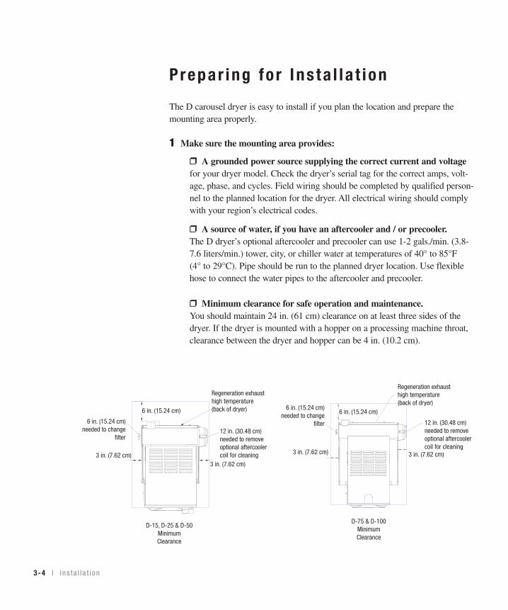
12 in. (30.48 cm)needed to removeoptional aftercoolercoil for cleaning
3 in. (7.62 cm)3 in. (7.62 cm)
Regeneration exhausthigh temperature (back of dryer)
6 in. (15.24 cm)6 in. (15.24 cm)
needed to changefilter
D-75 & D-100MinimumClearance
6 in. (15.24 cm)
12 in. (30.48 cm)needed to removeoptional aftercoolercoil for cleaning
3 in. (7.62 cm)3 in. (7.62 cm)
Regeneration exhausthigh temperature(back of dryer)
6 in. (15.24 cm)needed to change
filter
D-15, D-25 & D-50MinimumClearance
3-4 l I n s t a l l a t i on
Prepar ing fo r Ins ta l l a t ion
The D carousel dryer is easy to install if you plan the location and prepare themounting area properly.
1 Make sure the mounting area provides:
❒❒ A grounded power source supplying the correct current and voltagefor your dryer model. Check the dryer’s serial tag for the correct amps, volt-age, phase, and cycles. Field wiring should be completed by qualified person-nel to the planned location for the dryer. All electrical wiring should complywith your region’s electrical codes.
❒❒ A source of water, if you have an aftercooler and / or precooler.The D dryer’s optional aftercooler and precooler can use 1-2 gals./min. (3.8-7.6 liters/min.) tower, city, or chiller water at temperatures of 40° to 85°F(4° to 29°C). Pipe should be run to the planned dryer location. Use flexiblehose to connect the water pipes to the aftercooler and precooler.
❒❒ Minimum clearance for safe operation and maintenance.You should maintain 24 in. (61 cm) clearance on at least three sides of thedryer. If the dryer is mounted with a hopper on a processing machine throat,clearance between the dryer and hopper can be 4 in. (10.2 cm).

I n s t a l l a t i on l 3-5
6 inches(15.24 cm)square
5 inches(12.7 cm)
square
7/16 inches(1.11 cm)diameter
2 inches(5.08 cm)diameter
4 inches(10.16 cm)square
3 inches(7.62 cm)
square
7/16 inches(1.11 cm)diameter
1 inch(2.54 cm)diameter
NOTE: If your mountingsurface does not matchthe standard bolt pat-terns available, you willneed an adapter. Youcan make an adapterusing the dimensionsprovided or purchaseone from Conair.
❒❒ A mounting surface that will support the weight of the dryer, supportframe, and a fully-loaded hopper, or just the fully-loaded hopper. See thespecifications tables for weights and volumes.
❒❒ Material and conveying lines installed. If you plan to use vacuum orcompressed air loaders to fill the hopper, install conveying lines to the dryinghopper location.
2 Drill and tap mounting holes or make adapter.Available discharge assemblies and slide gates fit mounting surfaces withthese bolt patterns and diameters.
3D
escription
✐Prepar ing fo r Ins ta l l a t ion (cont inued)
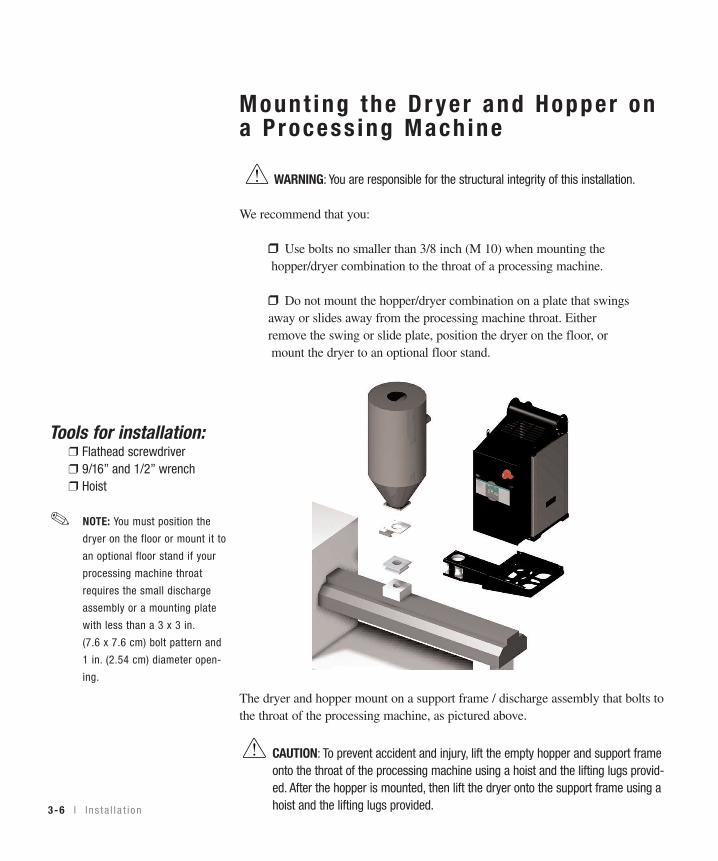
Mount ing the Dr yer and Hopper ona Process ing Mach ine
WARNING: You are responsible for the structural integrity of this installation.
We recommend that you:
❒❒ Use bolts no smaller than 3/8 inch (M 10) when mounting the hopper/dryer combination to the throat of a processing machine.
❒❒ Do not mount the hopper/dryer combination on a plate that swings away or slides away from the processing machine throat. Either remove the swing or slide plate, position the dryer on the floor, or mount the dryer to an optional floor stand.
The dryer and hopper mount on a support frame / discharge assembly that bolts tothe throat of the processing machine, as pictured above.
CAUTION: To prevent accident and injury, lift the empty hopper and support frameonto the throat of the processing machine using a hoist and the lifting lugs provid-ed. After the hopper is mounted, then lift the dryer onto the support frame using ahoist and the lifting lugs provided.
Tools for installation:❒ Flathead screwdriver❒ 9/16” and 1/2” wrench❒ Hoist
NOTE: You must position the
dryer on the floor or mount it to
an optional floor stand if your
processing machine throat
requires the small discharge
assembly or a mounting plate
with less than a 3 x 3 in.
(7.6 x 7.6 cm) bolt pattern and
1 in. (2.54 cm) diameter open-
ing.
✐
3-6 l I n s t a l l a t i on
3D
escription
Mount ing the Dr yer and Hopper ona Process ing Mach ine (cont inued)
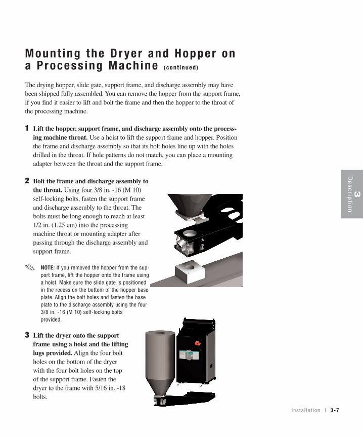
The drying hopper, slide gate, support frame, and discharge assembly may havebeen shipped fully assembled. You can remove the hopper from the support frame,if you find it easier to lift and bolt the frame and then the hopper to the throat ofthe processing machine.
1 Lift the hopper, support frame, and discharge assembly onto the process-ing machine throat. Use a hoist to lift the support frame and hopper. Positionthe frame and discharge assembly so that its bolt holes line up with the holesdrilled in the throat. If hole patterns do not match, you can place a mountingadapter between the throat and the support frame.
2 Bolt the frame and discharge assembly tothe throat. Using four 3/8 in. -16 (M 10)self-locking bolts, fasten the support frameand discharge assembly to the throat. Thebolts must be long enough to reach at least1/2 in. (1.25 cm) into the processingmachine throat or mounting adapter afterpassing through the discharge assembly andsupport frame.
NOTE: If you removed the hopper from the sup-port frame, lift the hopper onto the frame usinga hoist. Make sure the slide gate is positionedin the recess on the bottom of the hopper baseplate. Align the bolt holes and fasten the baseplate to the discharge assembly using the four3/8 in. -16 (M 10) self-locking boltsprovided.
3 Lift the dryer onto the supportframe using a hoist and the liftinglugs provided. Align the four boltholes on the bottom of the dryerwith the four bolt holes on the topof the support frame. Fasten thedryer to the frame with 5/16 in. -18bolts.
✐
I n s t a l l a t i on l 3-7

Pos i t i on ing the Dr yer on the F loor ;Mount ing the Hopper on the Throa t
WARNING: You are responsible for the structural integrity of this installation.
We recommend that you:
• Use bolts no smaller than 3/8 in. (M 10) to mount the hopper on the throat ofa processing machine.
The hopper bolts to the throat of the processing machine, as pictured above.The dryer can be positioned on the floor near the processing machine.
3-8 l I n s t a l l a t i on
Tools for installation:❒ 9/16” wrench❒ Flathead screwdriver❒ Hoist

I n s t a l l a t i on l 3-9
3D
escription
Mount ing the Hopper
CAUTION: To prevent accident and injury, lift the empty hopper onto the throat ofthe processing machine using a hoist and the lifting lugs provided. Also lift the dryer fromthe shipping container using a hoist and the lifting lugs provided.
1 Lift the hopper onto the throat. Lift the hopper with a hoist, using the liftinglugs provided. Make sure you align the bolt holes in the throat with the boltholes on the discharge assembly.
2 Bolt the hopper to the throat ofthe machine. Using four 3/8 in.-16(M 10) self-locking bolts, fastenthe support frame, discharge, andslide gate to the throat. The boltsmust be long enough to reach atleast 1/2 in. (1.25 cm) into themounting adapter or processingmachine throat, after passingthrough the discharge and slidegate.
Pos i t i on ing theDr yer on theF loor1 Lift the dryer from the shipping
container using a hoist and the liftinglugs provided.
2 Position the dryer on the floor nearthe processing machine. Make surethe location allows for the connectionof all hoses.
NOTE: Frame and castersare optional
✐

3-10 l I n s t a l l a t i on
Mount ing the Dr yer on the F loorS tand ; Hopper on the Throa tFor information about mounting the dryer on the floor stand and the hopper on thethroat, refer to Appendix B.
Mount ing the Dr yer and Hopper onthe Mob i le F loor S tand
For information about mounting the dryer and hopper on the mobile floor stand,refer to Appendix B.
Connect ing the Ma in Power
CAUTION: Always disconnect and lock out the main power sources before makingelectrical connections. Electrical connections should be made only by qualified personnel.
1 Open the dryer’s electrical enclo-sure. Turn the disconnect dial on thedryer door to the Off or O position.Lock out the main power (see Page1-4 for complete lock out informa-tion). Turn the captive screw, andswing the door open.
2 Insert the main power wirethrough the knockout in the side ofthe enclosure. Secure the wire witha rubber compression fitting orstrain relief.

I n s t a l l a t i on l 3-11
3D
escription
IMPORTANT: Always refer to thewiring diagrams that came withyour dryer before making electri-cal connections.
3 Connect the power wires to the three terminals at the top of the power discon-nect holder.
4 Connect the ground wire to either grounding point as shown in the photo.
Connect ing the Ma in Power (cont inued)

Check ing fo r P roper A i r F lowThis step is only needed on 50, 75, and 100 models.
CAUTION: This step must be performed before the dryer’s air hoses are connectedto the hopper. Performing this step after the air hoses are connected could causedamage to the dryer if the air flow direction is incorrect due to improper phaseconnection. Material from the hopper can be pulled into the process heater,causing permanent damage.
1 Turn on the main power to the dryer. Make sure the dryer’s disconnect dial isin the ON position. This powers up the control and the display lights will illu-minate.
2 Set the drying temperature to a low setpoint (or below 150°F. PressSetpoint Adjust ▲ or ▼ buttons to set the temperature.
3-12 l I n s t a l l a t i on

Check ing fo r P roper A i r F low (cont inued)
3 When the dryer is stopped, press the button to START. Hold your hand near the delivery air outlet. You should feel air blowing out of the outlet.
4 When the dryer is running, press the button to STOP.
I n s t a l l a t i on l 3-13
Moistureexhaust
Delivery air outlet(15, 25, and 50models)
ReturnAir Inlet
Delivery airoutlet (75 and100 models)
ReturnAir Inlet
Moistureexhaust
CAUTION: Hot surface Do not place your hand on the delivery air outlet.The outlet and the air can get hot enough to burn your hand.
3D
escription
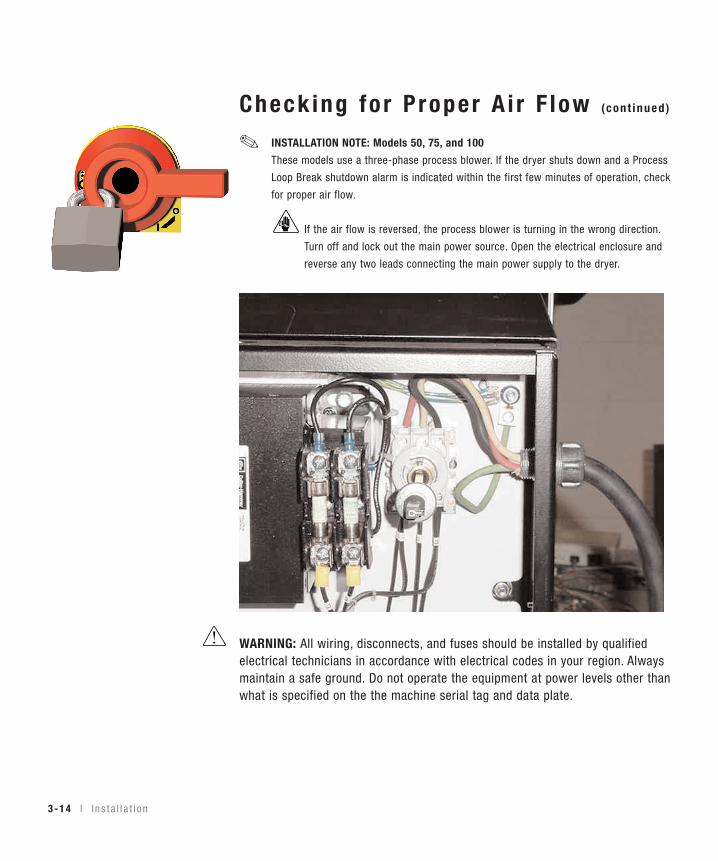
Check ing fo r P roper A i r F low (cont inued)
INSTALLATION NOTE: Models 50, 75, and 100
These models use a three-phase process blower. If the dryer shuts down and a Process
Loop Break shutdown alarm is indicated within the first few minutes of operation, check
for proper air flow.
If the air flow is reversed, the process blower is turning in the wrong direction.
Turn off and lock out the main power source. Open the electrical enclosure and
reverse any two leads connecting the main power supply to the dryer.
WARNING: All wiring, disconnects, and fuses should be installed by qualifiedelectrical technicians in accordance with electrical codes in your region. Alwaysmaintain a safe ground. Do not operate the equipment at power levels other thanwhat is specified on the the machine serial tag and data plate.
✐
3-14 l I n s t a l l a t i on

3D
escription
I n s t a l l a t i on l 3-15
Connec t ing the A i r HosesUsing the two flexible hoses provided, connect the inlets and outlets of the dry-ing hopper to the dryer. If you have positioned the dryer on the floor or mount-ed it to an optional floor stand, make sure the dryer is located no more than 5feet (1.5 m) from the hopper to reduce heat loss.
If you ordered an insulated hose, it should be installed between the dryer outletand the hopper inlet.
If you have ordered an optionalaftercooler or precooler, seeAppendices C and D.
1 Attach one hose from thereturn air inlet of the dryer tothe return air outlet of the hop-per.
2 Attach one hose from thedelivery air outlet of the dryerto the delivery air inlet of thehopper.
3 Secure hoses with clamps.The hose clamp should be secured atleast 1/4 in. (0.64 cm) from the end of the inlet or outlet tube.
Connect ing the Wate r HosesThe optional aftercooler, and precooler require a source of cooling water and a dis-charge or return line. See Appendix C for information on installing and connectingwater hoses to the optional aftercooler. See Appendix D for information oninstalling and connecting water hoses to the optional precooler.
NOTE: Do not allow the
flexible hoses to kink or
crimp.
✐
Delivery airoutlet (75 and100 models)
ReturnAir Inlet
Delivery air outlet(15, 25, and 50models)
ReturnAir Inlet
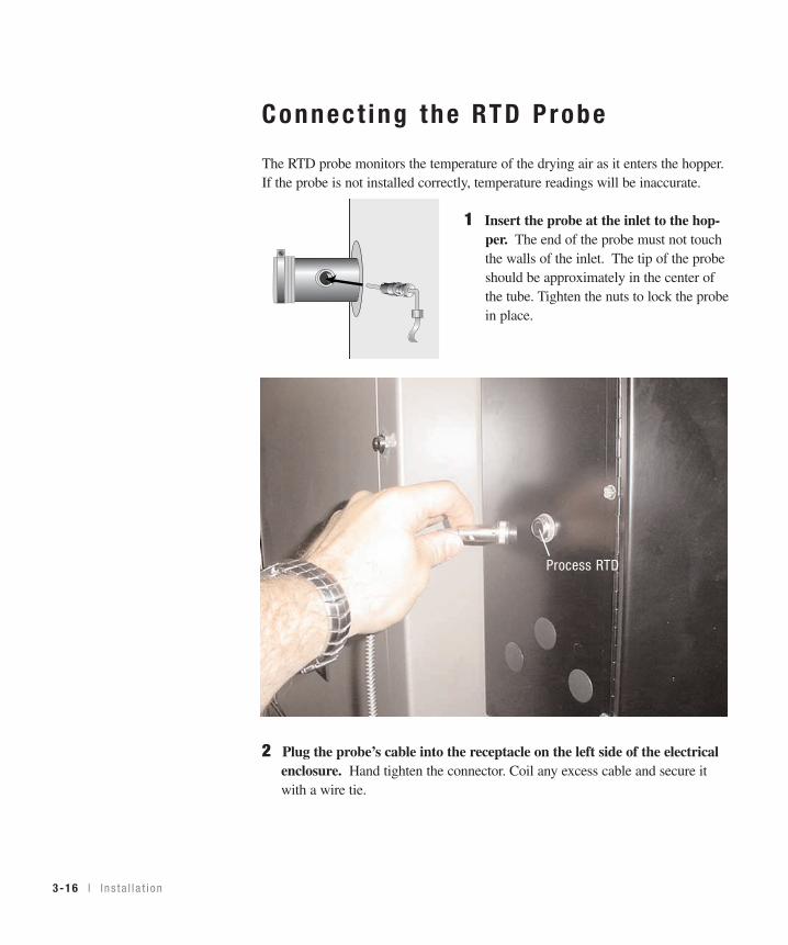
Connect ing the RTD Probe
The RTD probe monitors the temperature of the drying air as it enters the hopper.If the probe is not installed correctly, temperature readings will be inaccurate.
1 Insert the probe at the inlet to the hop-per. The end of the probe must not touchthe walls of the inlet. The tip of the probeshould be approximately in the center ofthe tube. Tighten the nuts to lock the probein place.
2 Plug the probe’s cable into the receptacle on the left side of the electricalenclosure. Hand tighten the connector. Coil any excess cable and secure itwith a wire tie.
3-16 l I n s t a l l a t i on
Process RTD

3D
escription
I n s t a l l a t i on l 3-17
Mount ing a Loader on the Hopper If you have a Conair loader or vacuum receiver, you canuse the flange and mounting clips provided on the top ofthe hopper. Refer to the manuals that came with yourreceiver or loader for detailed installation instructions.
Tes t ing The Ins ta l l a t ionYou have completed the installation. Now it’s time to makesure everything works.
1 Make sure there is no material in the hopper. If youhave mounted a loader or vacuum receiver on the hop-per, disconnect the material inlet hose at the source.
2 Turn on the main power to the dryer. Make sure thedryer’s disconnect dial is in the ON position. This pow-ers up the control and the display lights will illuminate.
3 Set the drying temperature. Press the Setpoint Adjust ▲ or ▼ buttons to setthe temperature.
(continued)

Tes t ing The Ins ta l l a t ion (continued)
4 Press the button.
If everything is installed correctly:
• The heater and blower lights will illuminate.• The process and regeneration blowers turn on.• The process and regeneration heaters turn on.• If the desiccant tanks are not in their correct position, the carousel will
turn clockwise and stop in the correct position.
5 Press the button.
NOTE: Under an Alarm Condition, pushing the Start/Stop/Acknowledge Alarm button
turns off the horn. Pushing the Start/Stop/Acknowledge Alarm button a second time
turns off the alarm LED.
If everything is installed correctly:
• The blowers will continue running as needed to cool the heaters.
6 The test is over. If the dryer performed the normal operating sequences asoutlined, you can load the hopper and begin operation. If it did not, refer to theTROUBLESHOOTING section of the User Guide.
3-18 l I n s t a l l a t i on
✐

S E C T I O N
44
Op
eration
Opera t ion
The DC d r ye r con t r o l pane l . . . . . . . . . . . . 4 -2
D d r ye r DC con t r o l f unc t i ons . . . . . . . . . . . 4 -3
Con t ro l f unc t i on f l o w cha r t . . . . . . . . . . . . 4 -3
Con t ro l f unc t i on desc r i p t i ons . . . . . . . . . . . 4 -6
To s t a r t d r y i ng . . . . . . . . . . . . . . . . . . . . 4 -20
To s t op d r y i ng . . . . . . . . . . . . . . . . . . . . 4 -20
Opera t i on l 4-1
The DC Dr yer Cont ro l Pane l
4-2 l Ope ra t i on
Star t /S top/Acknowledge A la rm But ton
Press the Start/Stop/Acknowledge button to start the dryer. Press the Start/Stop/Acknowledge button to stop the dryer. Under an alarm condition, pushing theStart/Stop/Acknowledge button once turns off the horn.Pushing the Start/Stop/Acknowledge button a second timeturns off the alarm LED
I nc rement /Decrement Bu t tonsUsed to increase ordecrease values.
Actua lD isp layShows the actualtemperature value.
Setpo in tD isp layShows the setpoint value.
AlarmCodes See“Troubleshooting”Section 6 for amore completelisting of alarmcodes.
Scro l l Bu t tonPress to scrollthrough theclosed loop menulist. Pressing thescroll buttonmoves you downthe list.

D Dr yer DC Cont ro l Func t ionsDryer functions are values that you can set or monitor. Press the Scroll button untilthe function you want to set or monitor appears in the LED display.
Cont ro l Func t ion F low Char t
The following flow chart provides a quick summary of the control functions. Foran explanation of each control function, see Control Function Description.
Opera t i on l 4-3
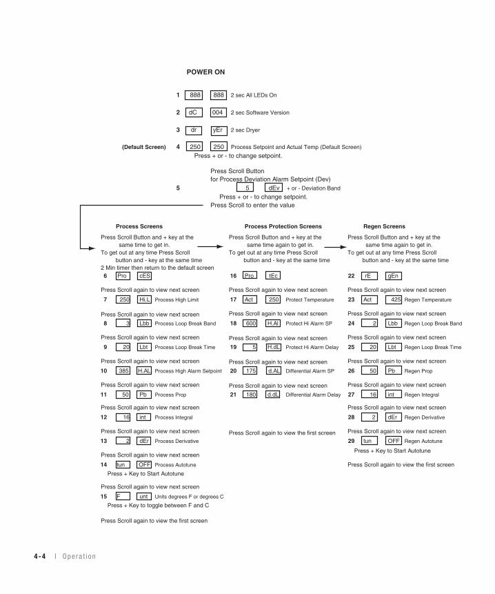
4-4 l Ope ra t i on
POWER ON
1 888 888 2 sec All LEDs On
2 dC 004 2 sec Software Version
3 dr yEr 2 sec Dryer
(Default Screen) 4 250 250 Process Setpoint and Actual Temp (Default Screen)
Press + or - to change setpoint.
Press Scroll Button for Process Deviation Alarm Setpoint (Dev)
5 5 dEv + or - Deviation Band
Press + or - to change setpoint.Press Scroll to enter the value
Process Screens Process Protection Screens Regen Screens
Press Scroll Button and + key at the Press Scroll Button and + key at the Press Scroll Button and + key at the same time to get in. same time again to get in. same time again to get in.To get out at any time Press Scroll To get out at any time Press Scroll To get out at any time Press Scroll button and - key at the same time button and - key at the same time button and - key at the same time2 Min timer then return to the default screen6 Pro cES 16 Pro tEc 22 rE gEn
Press Scroll again to view next screen Press Scroll again to view next screen Press Scroll again to view next screen
7 250 Hi.L Process High Limit 17 Act 250 Protect Temperature 23 Act 425 Regen Temperature
Press Scroll again to view next screen Press Scroll again to view next screen Press Scroll again to view next screen
8 3 Lbb Process Loop Break Band 18 600 H.Al Protect Hi Alarm SP 24 2 Lbb Regen Loop Break Band
Press Scroll again to view next screen Press Scroll again to view next screen Press Scroll again to view next screen
9 20 Lbt Process Loop Break Time 19 5 H.dL Protect Hi Alarm Delay 25 20 Lbt Regen Loop Break Time
Press Scroll again to view next screen Press Scroll again to view next screen Press Scroll again to view next screen
10 385 H.AL Process High Alarm Setpoint 20 175 d.AL Differential Alarm SP 26 50 Pb Regen Prop
Press Scroll again to view next screen Press Scroll again to view next screen Press Scroll again to view next screen
11 50 Pb Process Prop 21 180 d.dL Differential Alarm Delay 27 16 int Regen Integral
Press Scroll again to view next screen Press Scroll again to view next screen
12 16 int Process Integral 28 2 dEr Regen Derivative
Press Scroll again to view next screen Press Scroll again to view the first screen Press Scroll again to view next screen
13 2 dEr Process Derivative 29 tun OFF Regen Autotune
Press + Key to Start AutotunePress Scroll again to view next screen
14 tun OFF Process Autotune Press Scroll again to view the first screen
Press + Key to Start Autotune
Press Scroll again to view next screen
15 F unt Units degrees F or degrees C
Press + Key to toggle between F and C
Press Scroll again to view the first screen
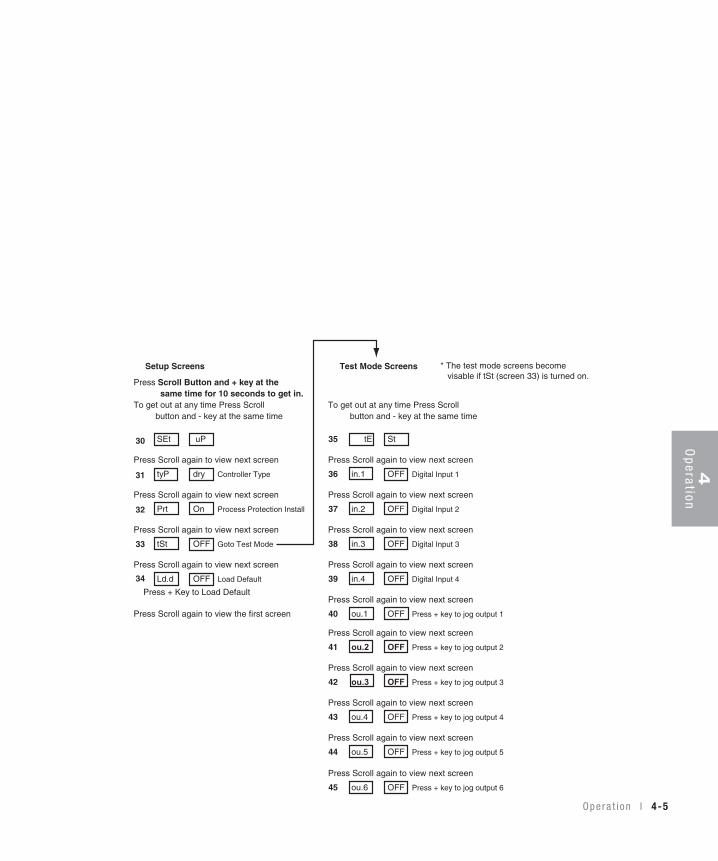
4O
peration
O pe ra t i on l 4-5
30
31
32
33
34
Setup Screens Test Mode Screens
Press Scroll Button and + key at the same time for 10 seconds to get in.To get out at any time Press Scroll To get out at any time Press Scroll button and - key at the same time button and - key at the same time
SEt uP 35 tE St
Press Scroll again to view next screen Press Scroll again to view next screen
tyP dry Controller Type 36 in.1 OFF Digital Input 1
Press Scroll again to view next screen Press Scroll again to view next screen
Prt On Process Protection Install 37 in.2 OFF Digital Input 2
Press Scroll again to view next screen Press Scroll again to view next screen
tSt OFF Goto Test Mode 38 in.3 OFF Digital Input 3
Press Scroll again to view next screen Press Scroll again to view next screen
Ld.d OFF Load Default 39 in.4 OFF Digital Input 4
Press + Key to Load DefaultPress Scroll again to view next screen
Press Scroll again to view the first screen 40 ou.1 OFF Press + key to jog output 1
Press Scroll again to view next screen
41 ou.2 OFF Press + key to jog output 2
Press Scroll again to view next screen
42 ou.3 OFF Press + key to jog output 3
Press Scroll again to view next screen
43 ou.4 OFF Press + key to jog output 4
Press Scroll again to view next screen
44 ou.5 OFF Press + key to jog output 5
Press Scroll again to view next screen
45 ou.6 OFF Press + key to jog output 6
* The test mode screens become visable if tSt (screen 33) is turned on.

General Screens
SCREEN 1
SCREEN 2
SCREEN 3
SCREEN 4Setpoint Actual
SCREEN 5
888
Funct ion
Cont ro l Func t ion Descr ip t ions
888
dC 004
dr yEr
250 250
10 dEv
4-6 l Ope ra t i on
Once the power is turned on, this screen isdisplayed for 2 seconds while the controlperforms its self-checking process. AllLEDs are illuminated during this 2-secondinterval.
After the self-checking process is com-plete, this screen flashes for 2 seconds anddisplays the software version.
After the software version is displayed,this screen appears for 2 seconds and iden-tifies that the control is setup for a dryer.
This is the default screen. It shows theprocess air temperature setpoint and theactual temperature measured at the inlet tothe drying hopper. The +/- buttons can beused to change the setpoint. Holding the+/- buttons in will cause the number toramp up faster the longer the buttons isheld. The display will return to the defaultscreen from anyplace in the menu structureif nothing is done for 10 minutes.
This is the process deviation temperaturealarm setpoint screen. It is used to set thedeviation temperature band around theprocess temperature setpoint. The range is5 - 20°F (2.5 - 10°C). The +/- buttons canbe used to change the setpoint. If thedryer goes outside the band, the dryer willdisplay a passive alarm (P1).

To access the process screens, press theScroll and “+” buttons at the same timeand hold for two seconds . To get out ofthe Process screens at any time, press theScroll and “-“ buttons at the same time.After two minutes, you will be returned tothe Default screen.
This is the process header screen. It indi-cates that all items below it pertain to theprocess temperature control.
This is the process high limit screen. It isused to set the high limit for the processtemperature. The +/- buttons can be usedto change the setpoint. If set at 250°F, theoperator cannot set the process setpointabove 250°F.
This is the process loop break band screen.It is used to set the temperature band forthe loop break alarm. The +/- buttons canbe used to change the setpoint.
This is the process loop break time screen.It is used to set the temperature band timefor the loop break alarm. The +/- buttonscan be used to change the temperatureband time. This is how they work togeth-er: When the actual temperature is outsidethe deviation band, if the temperature isnot moving toward the setpoint at a rategreater than or equal to X F over Y sec,then the dryer will alarm on loop break.Once the actual temperature is within thedeviation band, the loop break is ignored.
4O
peration
O pe ra t i on l 4-7
Process Screens
SCREEN 6
SCREEN 7
SCREEN 8
SCREEN 9
Pro
Funct ion
Cont ro l Func t ion Descr ip t ions
cES
375 Hi.L
3 Lbb
20 Lbt

Process Screens
SCREEN 10
SCREEN 11
SCREEN12
SCREEN 13
SCREEN 14
385
Funct ion
Cont ro l Func t ion Descr ip t ions (cont inued)
This is the process alarm high temperaturesetpoint screen. It is used to set the tem-perature at which the process high temper-ature shutdown alarm (A1) will shutdownthe dryer and display the alarm. The +/-buttons can be used to change the setpoint.
This is the process proportional bandscreen. It is used to change the propor-tional band value for the process controlloop. The +/- buttons can be used tochange the proportional band setpoint.
This is the process integral screen. It isused to change the integral value for theprocess control loop. The +/- buttons canbe used to change the integral value set-point.
This is the process derivative screen. It isused change the derivative value for theprocess control loop. The +/- buttons canbe used to change the derivative value set-point.
This is the process heater autotune screen.The autotune function can be turned on bypressing the “+” key. Once the “+” key ispressed, the screen will show “SEt” andthen start the autotune process. Once heat-ing starts, the screen will read “H.ru”.Autotuning may take a minute or so tocomplete. When finished, the display willread “don”. The new PID values are auto-matically saved.
H.AL
50 Pb
4-8 l Ope ra t i on
16 int
2 dEr
tun OFF

Process ScreensSCREEN 15
Funct ion
Cont ro l Func t ion Descr ip t ions (cont inued)
This is the temperature units screen. It isused to change the temperature displayfrom °F to °C or °C to °F.
Opera t i on l 4-9
4O
peration
F unt

ProcessPro tec t ionScreens
SCREEN 16
Protection
SCREEN 17
SCREEN 18
Funct ion
Cont ro l Func t ion Descr ip t ions (cont inued)
To access the process protection screens,press the Scroll and “+” buttons at the sametime and hold for two seconds from theprocess screens. To get out of the Processprotection screens at any time, press theScroll and “-“ buttons at the same time.
This is the process protection headerscreen. It indicates that all items below itpertain to the process protection actualtemperature and alarms.
This screen shows the process protectionactual temperature.
This is the process protection high temper-ature alarm setpoint screen. If the actualprocess protection temperature exceedsthis setpoint for the length of the processprotection high alarm delay, this alarm(A49) will trigger and the dryer will shut-down. For example if the actual processprotection temperature exceeds 600°F(316°C) for 10 seconds, the dryer will exe-cute a shutdown alarm. The +/- buttonscan be used to change the setpoint.
Pro tEc
4-10 l Ope ra t i on
Act 260
600 H.AI

ProcessPro tec t ionScreens
SCREEN 19
SCREEN 20
SCREEN 21
Funct ion
Cont ro l Func t ion Descr ip t ions (cont inued)
This is the process protection high alarmdelay screen. It is used to set the delaytime for the process protection high tem-perature alarm. If this time delay isexceeded, the dryer will execute a shut-down alarm (A49). The +/- buttons can beused to change the setpoint.
This is the process differential alarm set-point screen. If the actual process protec-tion temperature minus the actual processtemperature exceeds this setpoint for thelength of the process differential alarmdelay, this alarm (A50) will trigger and thedryer will shutdown. For example if theactual process protection temperature is300°F (148.9°C) and the actual processtemperature is 124°F (51.1°C) for 180 sec-onds, the dryer will execute a shutdownalarm. The +/- buttons can be used tochange the setpoint.
This is the process differential alarm delayscreen. This screen is used to change theprocess differential alarm delay time. The+/- buttons can be used to change the set-point.
180 d.dL
10 H.dL
Opera t i on l 4-11
4O
peration
175 d.AL

Regenera t ionScreens
SCREEN 22
SCREEN 23
SCREEN 24
SCREEN 25
Funct ion
Cont ro l Func t ion Descr ip t ions (cont inued)
To access the regeneration (regen) screens,press the Scroll and “+” buttons at thesame time and hold for two seconds fromthe process protection screens. To get outof the regeneration screens at any time,press the Scroll and “-“ buttons at the sametime.
This is the regen header screen. It indi-cates that all items below it pertain to theregen temperature control.
This screen shows the actual temperatureof the regen air.
This is the regen loop break band screen.It can be used to set the temperature bandfor the loop break alarm. The +/- buttonscan be used to change the temperatureband setpoint.
This is the regen loop break time screen.It can be used to set the temperature bandtime for the loop break alarm. The +/- but-tons can be used to change the temperatureband time Screens 24 and 25 are theregen loop break screens. This is how theywork together: When the actual tempera-ture is outside the deviation band, if thetemperature is not moving toward the set-point at a rate greater than or equal to X Fover Y sec, then the dryer will alarm onloop break. Once the actual temperature iswithin the deviation band, the loop break isignored.
4-12 l Ope ra t i on
rE gEn
Act 425
2 Lbb
40 Lbt
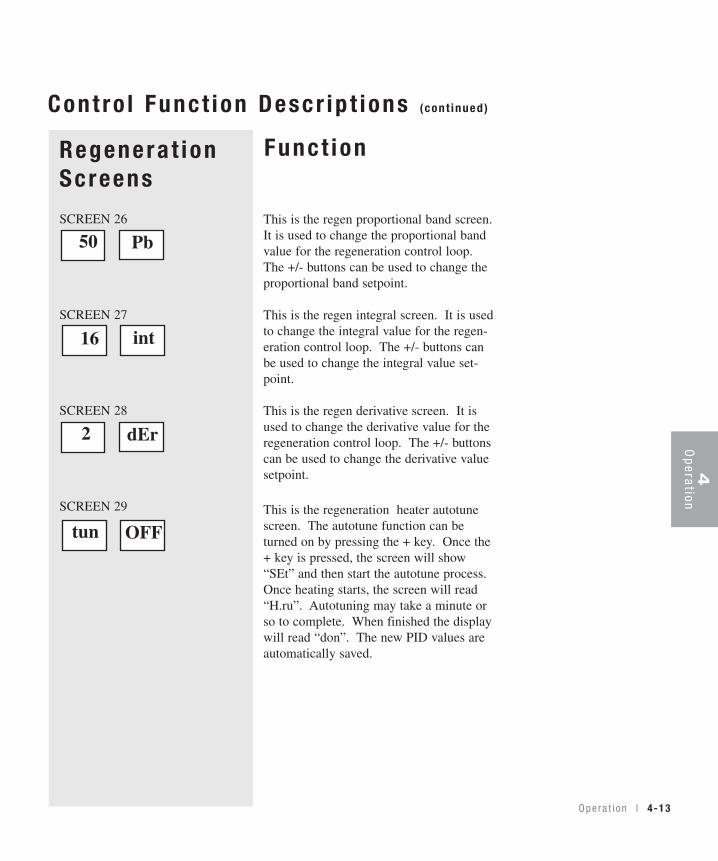
Regenera t ionScreens
SCREEN 26
SCREEN 27
SCREEN 28
SCREEN 29
Funct ion
Cont ro l Func t ion Descr ip t ions (cont inued)
This is the regen proportional band screen.It is used to change the proportional bandvalue for the regeneration control loop.The +/- buttons can be used to change theproportional band setpoint.
This is the regen integral screen. It is usedto change the integral value for the regen-eration control loop. The +/- buttons canbe used to change the integral value set-point.
This is the regen derivative screen. It isused to change the derivative value for theregeneration control loop. The +/- buttonscan be used to change the derivative valuesetpoint.
This is the regeneration heater autotunescreen. The autotune function can beturned on by pressing the + key. Once the+ key is pressed, the screen will show“SEt” and then start the autotune process.Once heating starts, the screen will read“H.ru”. Autotuning may take a minute orso to complete. When finished the displaywill read “don”. The new PID values areautomatically saved.
Opera t i on l 4-13
4O
peration
50 Pb
16 int
2 dEr
tun OFF

Funct ion
Cont ro l Func t ion Descr ip t ions (cont inued)
4-14 l Ope ra t i on
Setup Screen
SCREEN 30
SCREEN 31
SCREEN 32
SCREEN 33
SCREEN 34
To access the setup screens, press theScroll and "+" buttons at the same timeand hold for ten seconds. To get out of thesetup screens at any time, press the Scrolland "-" buttons at the same time.
This is setup header screen. It indicatesthat all items below it pertain to dryersetup functions.
The DC controller can be setup to controla dryer or a resin works heater. Thisshould always be set to "dry" when used tocontrol a dryer.
This screen states that process protectionhas been installed. This should always beset to "ON" when used to control a dryer.
This is the test screen. Press the "+" keyto enter the test mode.
This is the load defaults screen. Pressingthe "+" key will load all default values andsetpoints. Once this is done all parametersmust be reset.
WARNING: All setpoints revertback to the default values.
tyP dry
SEt uP
tSt OFF
Prt On
Ld.d OFF

Cont ro l Func t ion Descr ip t ions (cont inued)
Opera t i on l 4-15
4O
peration
Tes t ModeScreens
SCREEN 35
SCREEN 36
SCREEN 37
SCREEN 38
Funct ion
To access the test mode screens, press "+"button when you are in the test screen. Toget out of the test mode screens at any time,press the Scroll and "-" buttons at the sametime.
This is the test mode header screen. It indi-cates that all items below it are test func-tions.
This screen shows the state of digital input 1.If the input is open, "OFF" will be displayed.If the input is closed, "ON" will be dis-played. Digital input 1 on a dryer is theprocess high temperature switch. Thisswitch is closed during normal operation. Itopens when it detects a high temperatureinside the process heater tube.
This screen shows the state of digital input 2.If the input is open, "OFF" will be displayed.If the input is closed, "ON" will be dis-played. Digital input 2 on a dryer is theregen high temperature switch. This switchis closed during normal operation. It openswhen it detects a high temperature inside theregen heater tube.
This screen shows the state of digital input 3.If the input is open, "OFF" will be displayed.If the input is closed, "ON" will be dis-played. Digital input 3 on a dryer is the bed-plate limit switch. This switch is open whenthe bedplate is in the drying position. Thisswitch closes when the dryer is indexing.
in.1 On
tE St
in.3 On
in.2 On

Cont ro l Func t ion Descr ip t ions (cont inued)
4-16 l Ope ra t i on
Tes t ModeScreensSCREEN 39
SCREEN 40
SCREEN 41
SCREEN 42
Funct ion
This screen shows the state of digital input4. If the input is open, "OFF" will be dis-played. If the input is closed, "ON" willbe displayed. Digital input 4 on a dryer isthe process blower motor starter overloadauxiliary contact. The contact is open dur-ing normal operation when the overload isnot tripped. If an overload conditionoccurs, this contact closes and turns theinput to "ON".
This is the output 1 screen. Press the "+"key to jog output 1. Output 1 on a dryer isthe process and regen blowers. Pressingthe "+" key for 2 seconds will cause theprocess and regen blowers to run.
This is the output 2 screen. Press the "+"key to jog output 2. Output 2 on a dryer isthe bed drive motor. Pressing the "+" keywill cause the dryer to index one position.
This is the output 3 screen. Press the "+"key to jog output 3. Output 3 on a dryer isthe process heater solid-state relay signal.Pressing the "+" key will cause the processsolid-state relays to fire. You can observethe solid-state relay LED to check this out-put. Since the isolation contactor is open,the heater does not come on because itdoes not have power.
ou.2 OFF
ou.1 OFF
ou.3 OFF
in.4 OFF

Funct ion
Cont ro l Func t ion Descr ip t ions (cont inued)
Opera t i on l 4-17
4O
peration
(continued)
Tes t ModeScreensSCREEN 43
SCREEN 44
SCREEN 45
This is the output 4 screen. Press the "+"key to jog output 4. Output 4 on a dryer isthe regen heater solid-state relay signal.Pressing the "+" key will cause the regensolid-state relays to fire. You can observethe solid-state relay LED to check this out-put. Since the isolation contactor is open,the heater does not come on because itdoes not have power.
This is the output 5 screen. Press the "+"key to jog output 5. Output 5 on a dryer isthe process and regen heater power isola-tion contactor signal. Pressing the "+" keywill cause the isolation contactor to close.Watch the isolation contactor pull in tocheck this output. Since the solid-staterelays are not on, the heaters does notcome on because they do not have power.
This is the output 6 screen. Press the "+"key to jog output 6. Output 6 on a dryer isthe alarm horn. Pressing the "+" key willcause the alarm horn to sound.
ou.6 OFF
ou.5 OFF
ou.4 OFF

4-18 l Ope ra t i on
Dr yer DC Cont ro l A la rmsPASSIVE ALARMS
Passive alarms flash the alarm code and display process temperature until thealarm condition goes away, or it becomes a shutdown alarm.
Code Descr ip t ion A la rm LEDP1 Process Temperature Deviation Blinking RedP3 Regen Temperature Deviation Blinking Red
S H U T D O W N A L A R M S
Shutdown alarms flash the alarm code and display process temperature. The dryershould stop when both process and regen temps are below 150°F (65.6°C) or after10 minutes has passed (whichever occurs first), but should still flash the alarmcode until the Start/Stop/Acknowledge Alarm button is pressed. If the alarm con-dition is still active the dryer cannot start, it will flash alarm code again. If thealarm condition is not active, the display should return to the normal default screendisplay and the dryer is ready to run.
Code Descr ip t ion A la rm LEDA1 Process High Temperature Solid RedA2 Process Temperature Loop Break Solid RedA3 Process Heater box High Temperature Solid RedA4 Regen Heater box High Temperature Solid RedA5 Carousel Index Too Long Alarm Solid RedA6 Carousel Index Failure Solid RedA10 RTD Integrity Solid RedA26 Regen High Temperature Solid RedA35 Regen Temperature Loop Break Solid RedA39 EEProm Write Error-Internal Control Solid Red
Board ProblemA49 Process Protection High Alarm Solid RedA50 Process Differential Alarm Solid RedA53 Process Blower Overload Alarm Solid Red

To S ta r t D r y ing1 Make sure there is material in the hopper.
2 Turn on the main power to the dryer. Make surethe dryer’s disconnect dial is in the ON position. Thispowers up the control and the display lights will illu-minate.
3 Set the drying temperature. Press the AdjustSetpoint ▲ or ��buttons to select the temperature.
(continued)
4O
peration
O pe ra t i on l 4-19

To S ta r t D r y ing (continued)
4 Press the button.
If everything is installed correctly:• • The process and regeneration blowers turn on.• The process and regeneration heaters turn on.• If the desiccant tanks are not in their correct position, the carousel will
turn clockwise and stop in the correct position.
To S top Dr y ing1 Press the button. The blower light stays on.
• The blowers continue running for a few minutes to cool the heaters.
2 Be sure to disconnect and lockout themain power if you have stopped the dryer toperform maintenance or repair.
IMPORTANT: Do not use the main power switch tostop the dryer. Turning off power to the controland dryer during normal operation prevents thenecessary cool-down period, and can trigger theshut down/high temperature alarm during yournext drying cycle.
Caution: Improper shut down can cause damage to your dryer.
4-20 l Ope ra t i on

Main tenance
Preven ta t i ve ma in tenance check l i s t . . . . . . . 5 -2
C lean ing t he hoppe r . . . . . . . . . . . . . . . . . 5 -3
C lean ing t he p rocess f i l t e r . . . . . . . . . . . . . 5 -4
C lean ing t he r egene ra t i on f i l t e r . . . . . . . . . 5 -4
C lean ing t he a f t e r coo l e r co i l s . . . . . . . . . . . 5 -5
C lean ing t he p recoo l e r co i l s . . . . . . . . . . . . 5 -5
Inspec t i ng hoses and gaske t s . . . . . . . . . . . 5 -5
S E C T I O N
5M
ainten
ance
5
Main tenance l 5-1
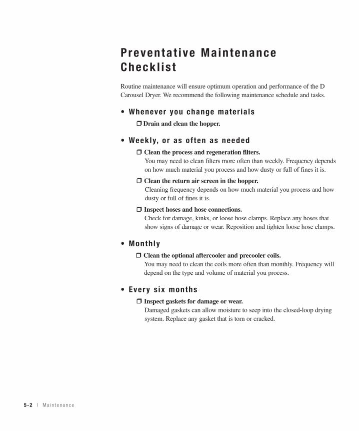
5-2 l Ma in tenance
Preventa t i ve Ma in tenanceCheck l i s tRoutine maintenance will ensure optimum operation and performance of the DCarousel Dryer. We recommend the following maintenance schedule and tasks.
• Whenever you change mater ia ls❒❒ Drain and clean the hopper.
• Week ly, o r as o f ten as needed❒❒ Clean the process and regeneration filters.
You may need to clean filters more often than weekly. Frequency dependson how much material you process and how dusty or full of fines it is.
❒❒ Clean the return air screen in the hopper.Cleaning frequency depends on how much material you process and how dusty or full of fines it is.
❒❒ Inspect hoses and hose connections.Check for damage, kinks, or loose hose clamps. Replace any hoses thatshow signs of damage or wear. Reposition and tighten loose hose clamps.
• Month ly❒❒ Clean the optional aftercooler and precooler coils.
You may need to clean the coils more often than monthly. Frequency will depend on the type and volume of material you process.
• Ever y s ix months❒❒ Inspect gaskets for damage or wear.
Damaged gaskets can allow moisture to seep into the closed-loop drying system. Replace any gasket that is torn or cracked.

5M
ainten
ance
Ma i n t enance l 5-3
C lean ing the Hopper
CAUTION: Hot surfaces. Always protect yourself from hot surfaces inside and out-side the dryer and drying hopper.
The hopper, spreader cone, and discharge assembly should be cleaned thoroughlybetween material changes to prevent resin contamination.
Place a container beneath the hopper’s drain port to catch the material.
1 Close the hopper slide gate.
2 Remove the drain-port plug. Pullthe pin and allow the plug to drop.Open the slide gate and allow mate-rial to drain.
3 Remove the spreader cone. Open the hopper door. Reach into the hopper.Grasp the spreader cone tube, lift up slightly, twist and then push down torelease it. Tilt the cone assembly and pull it out through the hopper door.
4 Clean the spreader cone and the inside of the hopper.Make sure you also clean the return air screen at the returnair outlet of the hopper.
5 Repeat the steps in reverse order to reassemble the hop-per before adding material.

5-4 l Ma in tenance
Clean ing the P rocess F i l t e rClogged filters reduce air flow and dryer efficiency. Cleaning frequency dependson how much material you process and how dusty it is.
1 Remove the process filter.Remove the black plastic knob.Pull the cap off. Remove thewing nut. Remove the filter capand filter.
2 Clean the filter tube.
3 Using compressed air, cleanthe process filter by blowing airfrom the inside out. Replacedamaged, worn, or clogged filters.
4 Reverse the procedure to reinstall the process filter.
Clean ing the Regenera t ion F i l t e rClogged filters reduce air flow and dryer efficiency. Cleaning frequency dependson how much material you process and how dusty it is.
1 Remove the regeneration filter.Remove the two bolts and the metalscreen.
2 Clean the regeneration filter. Cleandust, fines, and dirt from the filter,or replace it with a new filter.
3 Reverse the procedure to reinstall the regeneration filter.
CAUTION: Wear eye protection. If you use compressed air to clean the equipment, youmust wear eye protection and observe all OSHA and other safety regulations pertainingto the use of compressed air.

5M
ainten
ance
Ma i n t enance l 5-5
C lean ing the A f te rcoo le r Co i l sIf you have the optional aftercooler, you need to clean the cooling coils to keepthem working efficiently. See Appendix C for details.
Clean ing the P recoo le r Co i l s If you have the optional precooler, you need to clean the cooling coils to keepthem working efficiently. See Appendix D for details.
I nspec t ing Hoses and Gaske ts
Loose or damaged hoses and gaskets can allow moisture to seep into the closed-loop drying system.
1 Follow the hose routing of all the hoses within the dryer and inspect allhoses, clamps, fittings, and gaskets.
2 Tighten any loose hose clamps or fittings.
3 Replace worn or damaged hoses and gaskets.

5-6 l Ma in tenance

Troub leshoot ing
Be fo re beg inn ing . . . . . . . . . . . . . . . . . . . 6 -2
A f ew words o f cau t i on . . . . . . . . . . . . . . 6 -3
D IAGNOST ICS
Ho w to i den t i f y t he cause o f a p rob l em . . . . 6 -4
Shu t do wn a l a rms . . . . . . . . . . . . . . . . . 6 -5
Pass i ve a l a rms . . . . . . . . . . . . . . . . . . . 6 -10
REPA IR
Rep lac ing f uses . . . . . . . . . . . . . . . . . . . 6 -11
Check ing hea te r so l i d s t a t e r e l ays . . . . . . . 6 -12
Check ing o r r ep l ac i ng t empera tu re senso rs . 6 -13
Ad jus t i ng t he l im i t s w i t ch . . . . . . . . . . . . 6 -14
Rep lac ing t he hea te r s . . . . . . . . . . . . . . . 6 -15
Rep lac ing t he des i ccan t t anks . . . . . . . . . . 6 -19
Re f i l l i ng t he des i ccan t t anks . . . . . . . . . . 6 -20
S E C T I O N
66
Troubleshooting
Tr oub l eshoo t i ng l 6-1

6-2 l Tr oub leshoo t i ng
Before Beg inn ingYou can avoid most problems by following the recommended installation andmaintenance procedures outlined in this User Guide. If you do have a problem,this section will help you determine what caused it and how to fix it.
Before you take the side panels off of the dryer be sure to:
❏ Diagnose causes from the control panel. 1 Press once to silence the optional audible alarm and display the
alarm message.
2 Address the alarm message and fix the problem.
3 Press again to clear the alarm. If the alarm reappears the problem was not fixed.
If the alarm is a passive alarm you will see P in the screen title display.
If the alarm is a shut down alarm you will see A in the screen title display.
❏ Diagnose causes from the front of the dryer. You can identify any problem from the front of the dryer.
Start/Stop/Acknowledgealarm button
Scrollbutton

6Troubleshooting
Tr oub l eshoo t i ng l 6-3
❏ Find the wiring and equipment diagrams that were shipped withyour dryer. These diagrams are the best reference for correcting a prob-lem. The diagrams also will note any custom features, such as specialwiring or alarm capabilities, not covered in this User Guide.
A Few Words o f Caut ionThe D Carousel dryer is equipped with numerous safety devices. Do notremove or disable them. Improper corrective action can lead to hazardousconditions and should never be attempted to sustain production.
WARNING: Only qualified service personnel should examine and correctproblems that require opening the dryer’s electrical enclosure or usingelectrical wires to diagnose the cause.
WARNING: High voltage. Always stop the D Carousel dryer,disconnect and lock out the main power source before troubleshootingor performing repairs.
CAUTION: Hot surfaces. Always protect yourself from hot surfaces insideand outside of the dryer and hopper.
Open the electricalenclosure to checkfuses and heater contactors.
Note: Picture only representativeof the dryer. Yours may not lookexactly the same.
✐

6-4 l Tr oub leshoo t i ng
How to Iden t i f y the Cause o f aProb lemMost dryer malfunctions are indicated by an illuminated Acknowledge Alarm lighton the D carousel dryer control panel.
A problem can trigger two types of alarms:
• Shut Down: The dryer has automatically shut down because it detected a serious problem that could damage your material or dryer.
• Passive: The dryer continues to operate, but warns of a problem that could prevent correct drying of your material. If ignored, this problem could lead to a condition that will shut down the dryer.
When the alarm light is displayed:
1 Press the button once to silence the optional audible alarm and display the alarm message. Pressing the Acknowledge Alarm button once also changes the alarm LED fromblinking to solid.
2 Find the error message in the diagnostics table of this troubleshootingsection.
3 Note that pressing the button a second time will clear the alarm.
Start/Stop/AcknowledgeAlarm button
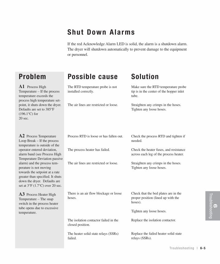
Troub leshoo t i ng l 6-5
Shu t Down A la rmsIf the red Acknowledge Alarm LED is solid, the alarm is a shutdown alarm.The dryer will shutdown automatically to prevent damage to the equipmentor personnel.
Possible causeThe RTD temperature probe is notinstalled correctly.
The air lines are restricted or loose.
Process RTD is loose or has fallen out.
The process heater has failed.
The air lines are restricted or loose.
There is an air flow blockage or loosehoses.
The isolation contactor failed in theclosed position.
The heater solid state relays (SSRs)failed.
SolutionMake sure the RTD temperature probetip is in the center of the hopper inlettube.
Straighten any crimps in the hoses.Tighten any loose hoses.
Check the process RTD and tighten ifneeded.
Check the heater fuses, and resistanceacross each leg of the process heater.
Straighten any crimps in the hoses.Tighten any loose hoses.
Check that the bed plates are in theproper position (lined up with thehoses).
Tighten any loose hoses.
Replace the isolation contactor.
Replace the failed heater solid staterelays (SSRs).
ProblemA1 Process HighTemperature – If the processtemperature exceeds theprocess high temperature set-point, it shuts down the dryer.Defaults are set to 385°F(196.1°C) for 20 sec.
A2 Process TemperatureLoop Break – If the processtemperature is outside of theoperator entered deviation,alarm band (see Process HighTemperature Deviation passivealarm) and the process tem-perature is not movingtowards the setpoint at a rategreater than specified. It shutsdown the dryer. Defaults areset at 3°F (1.7°C) over 20 sec.
A3 Process Heater HighTemperature – The snapswitch in the process heatertube opens due to excessivetemperature.
6Troubleshooting

6-6 l Tr oub leshoo t i ng
Shut Down A la rms
Problem
A4 Regen Heater HighTemperature – The snap switchin the regeneration heater tubeactivated due to excessive tem-perature.
A5 Carousel Index Too LongAlarm – If the carousel indexwas more than 1.5 times thenormal index time, it shutsdown the dryer.
A6 Carousel Index Failure –If the carousel index isrequested but no contact transi-tion from on to off is seenwithin 5 sec, it shuts downdryer.
Possible causeThe regeneration exhaust is blocked orthe air hoses are loose.
The isolation contactor failed in theclosed position.
The heater solid state relays (SSRs)failed.
The limit switch is not adjustedcorrectly.
The limit switch is not adjustedcorrectly.
The bed drive motor is damaged.
The set screw on the bed drive motorshaft plate is loose.
The bed drive motor relay has failed.
SolutionCheck that the bed plates are in theproper position (lined up with thehoses). See “Adjusting the limit switch”.
Tighten any loose hoses.
Replace the isolation contactor.
Replace the failed heater solid state
relays (SSRs).
Adjust the limit switch so that it dropsinto the groove and stops the bed plates.See “Adjusting the limit switch”.
Adjust the limit switch so that it dropsinto the groove and stops the bed plates.
Replace the bed drive motor.
Tighten the set screw. Make sure it is onthe flat of the D shaped shaft.
Replace the bed drive motor relay.

Troub leshoo t i ng l 6-7
Shu t Down A la rms
ProblemA10 RTD Integrity – If theprocess RTD is faulty
A26 Regen HighTemperature – If the regenera-tion temperature exceeds thehigh temperature limit for thespecified time. Default valuesare 450°F (232.2°C) for 20sec.
A35 Regen TemperatureLoop Break – The regenera-tion temperature is outside ofthe operator entered deviationalarm band (see RegenTemperature Deviation passivealarm) and the regenerationtemperature is not movingtowards the setpoint at a rategreater than specified. Defaultvalues are 2°F (1°C) over 40sec.
A39 EEProm Write Error
Possible causeThe connection in the electrical enclo-sure for the process RTD is loose.
The connection of the RTD plug on thecontrol board is loose.
The process RTD has failed.
One of the solid state relays (SSRs)failed in the closed position.
The regeneration RTD is loose or hasfallen out.
The regeneration heater has failed.
The regeneration RTD is loose or hasfallen out.
Internal Control board problem.
SolutionCheck the RTD plug connection andtighten if needed.
Check the plug connection and tighten ifneeded.
Replace the process RTD.
Replace the failed solid state relays(SSRs).
Check the regeneration RTD and tightenif needed.
Check the heater fuses, and resistanceacross each leg of the process heater.
Check the regeneration RDT and tightenif needed.
Replace the Control board.
6Troubleshooting
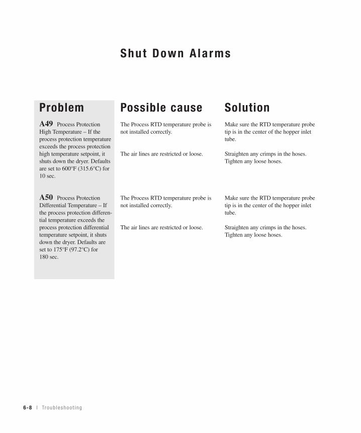
6-8 l Tr oub leshoo t i ng
Shut Down A la rms
ProblemA49 Process ProtectionHigh Temperature – If theprocess protection temperatureexceeds the process protectionhigh temperature setpoint, itshuts down the dryer. Defaultsare set to 600°F (315.6°C) for 10 sec.
A50 Process ProtectionDifferential Temperature – Ifthe process protection differen-tial temperature exceeds theprocess protection differentialtemperature setpoint, it shutsdown the dryer. Defaults areset to 175°F (97.2°C) for 180 sec.
Possible causeThe Process RTD temperature probe isnot installed correctly.
The air lines are restricted or loose.
The Process RTD temperature probe isnot installed correctly.
The air lines are restricted or loose.
SolutionMake sure the RTD temperature probetip is in the center of the hopper inlettube.
Straighten any crimps in the hoses.Tighten any loose hoses.
Make sure the RTD temperature probetip is in the center of the hopper inlettube.
Straighten any crimps in the hoses.Tighten any loose hoses.
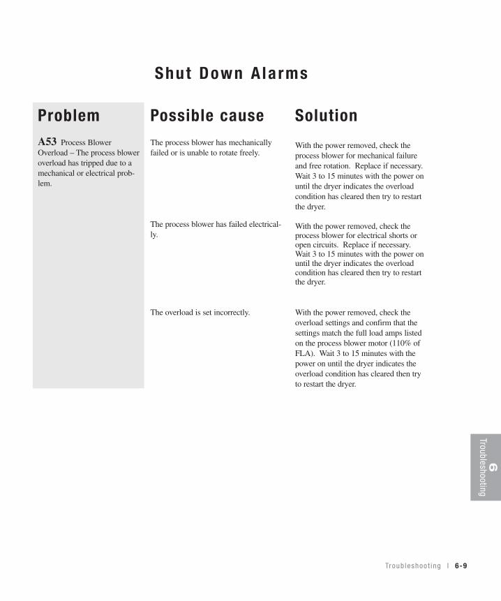
Troub leshoo t i ng l 6-9
6Troubleshooting
Possible causeThe process blower has mechanicallyfailed or is unable to rotate freely.
The process blower has failed electrical-ly.
The overload is set incorrectly.
Solution
With the power removed, check theprocess blower for mechanical failureand free rotation. Replace if necessary.Wait 3 to 15 minutes with the power onuntil the dryer indicates the overloadcondition has cleared then try to restartthe dryer.
With the power removed, check theprocess blower for electrical shorts oropen circuits. Replace if necessary.Wait 3 to 15 minutes with the power onuntil the dryer indicates the overloadcondition has cleared then try to restartthe dryer.
With the power removed, check theoverload settings and confirm that thesettings match the full load amps listedon the process blower motor (110% ofFLA). Wait 3 to 15 minutes with thepower on until the dryer indicates theoverload condition has cleared then tryto restart the dryer.
ProblemA53 Process BlowerOverload – The process bloweroverload has tripped due to amechanical or electrical prob-lem.
Shut Down A la rms

6-10 l Tr oub leshoo t i ng
Pass ive A la rmsIf the red Acknowledge Alarm LED is blinking, the alarm is a passive alarm. Thedryer continues to operate, but this problem could prevent correct drying of yourmaterial. Note that once the Acknowledge Alarm button is pressed once, the blink-ing red LED becomes solid.
ProblemP1 Process TemperatureDeviation – The process tem-perature exceeds the deviationband as entered for the speci-fied time. Default values are10°F (6°C) for 5 sec.
P3 Regen TemperatureDeviation – The regenerationtemperature exceeds the devi-ation band for the specifiedtime. Default values are 10°F (6°C) for 5 sec.
Possible causeOne of the solid state relays (SSRs)failed in the closed position.
The process RTD is loose or has fallenout.
The air hose connections are loose.
One of the solid state relays (SSRs)failed in the closed position.
The regeneration RTD is loose or hasfallen out.
The air hose connections are loose.
SolutionReplace the failed solid state relays(SSR).
Check the process RTD and tighten ifneeded.
Tighten all air hose connections.
Replace the failed solid state relays(SSRs).
Check the regeneration RTD and tightenif needed.
Tighten all air hose connections.

Rep lac ing Fuses1 Disconnect and lockout the main power supply.
2 Open the electrical enclosure door.
3 Check the fuse. If necessary, pull the fuse out and replace it with a fuse of thesame type and rating.
Fuse BlocksTo locate the appropriate fuseand replacement part, refer tothe wiring diagrams thatcame with your dryer.
IMPORTANT: Always referto the wiring diagrams thatcame with your dryer tolocate specific electricalcomponents. Illustrations inthe User Guide are intendedto be representative only.
6Troubleshooting
Tr oub l eshoo t i ng l 6-11

6-12 l Tr oub leshoo t i ng
Check ing Hea te r So l id S ta te Re lays1 Disconnect and lockout the main power supply.
2 Open the electrical enclosure.
3 Locate the process or regeneration relays. Refer to the wiring diagrams thatcame with your dryer.
4 Check continuity using an ohmmeter.
IMPORTANT: Always referto the wiring diagrams thatcame with your dryer tolocate specific electricalcomponents. Illustrations inthe User Guide are intendedto be representative only.
Regeneration heatersolid state relaysIf ohms equal zero or infinity,replace the solid state relay. Process heater
solid state relaysIf ohms equal zero or infinity,replace the solid state relay.

Troub leshoo t i ng l 6-13
Check ing o r Rep lac ing Tempera tureSensorsThe D carousel dryer uses RTD sensors to monitor the temperatures of the dryingair, the regeneration air, and the heater box process protection.
To check or replace an RTD sensors:
1 Disconnect and lockout the main power supply.
2 Remove dryer panels, as necessary.
3 Locate the RTD sensors.
4 Check the sensor positions and conditions. Temperature readings will beincorrect, if the sensors are touching the wall of an air hose or pipe or if the sen-sor or wiring is damaged. The tip of the sensor should be centered within the airhose or pipe. Sensor wires should be attached to the appropriate connectionpoints on the dryer’s electrical enclosure or microprocessor board.
5 To check with ohm meter - measure the resistance across the RTDs. The resistance should be approx. 110 ohm at room temperature.
6 Replace the sensor, if necessary.
IMPORTANT: Always referto the wiring diagramsthat came with your dryerto locate specific electri-cal components.Illustrations in the UserGuide are intended to berepresentative only.
Location ofthe ProcessRTD at theHopper
6Troubleshooting

6-14 l Tr oub leshoo t i ng
Adjus t ing the L imi t Swi tch
1 Stop the dryer. Disconnect and lockout the main power.
2 Remove the right side panel from the dryer.
IMPORTANT: Note the position of the tanks.
3 Loosen the screws securing the limit switch to the carousel. Note that thehole for the front screw is slotted to allow for adjustment.
4 Slide the switch to the left or right to position the limit switch so that its smallroller drops into the valley on the bed plate. The roller on the switch should nothit the stationary bottom plate.
5 Test for correct indexing of the carousel. Restore main power to the dryer.With the dryer powered, but not started you can engage the limit switch and thecarousel will turn. Once the bed plate starts turning, release the switch.
If everything is adjusted correctly:• The carousel bed turns.• When the limit switch reaches the next valley in the bed plate, the carousel
should stop turning.
6 Reset the desiccant carousel.Continue indexing until the desiccant tanks return to the positions they were inwhen the dryer shut down.

Troub leshoo t i ng l 6-15
6Troubleshooting
Rep lac ing the Hea te rsRegenera t ion Hea te r
1 Disconnect and lockout the main power at the power source.
2 Open the electrical enclosure door.
3 Reference the wiring diagram and / or trace the wires from the regenera-tion heater tube into the control box. Remove the wires from the relays andterminal strips. Once disconnected, pull the wires from the control box intothe dryer housing toward the heater tube.
4 Gain access to the regeneration heater by removing the rightdryer side panel.
5 Remove the hose and hose clamp at the bottom of the heater tube.
6 Remove the insulation from the heater tube by cutting the insulation in astraight line from top to bottom.
7 Remove the small 1/8" (3.18 mm) plastic hose from the hose barb, and remove the hose barb. Save the barb, it will need to be installed in the newheater tube.
8 Remove and save the regeneration RTD and fitting. They will be installedin the new heater.
99 Remove the heater tube by twisting the tube counterclockwise. The tubeis threaded into the lower bed plate. You may need to use a pipe wrench orchain wrench to remove it.
10 Check the ID mark on the side of the heater tube for kW rating and volt-age. The ID mark is on the outside of the tube near the end with the leadwires. Make sure the kW and voltage is the same as the replacement heater.
11 Thread the new heater into the lower bed plate. The RTD should be point-ing directly toward the back of the dryer. Do not over tighten. Hand tighten,and use a wrench for no more than one turn to get RTD into the correct posi-tion.
Note: When installed the regener-ation heater tube must be orientedso the RTD is directly toward theback of the dryer.
✐
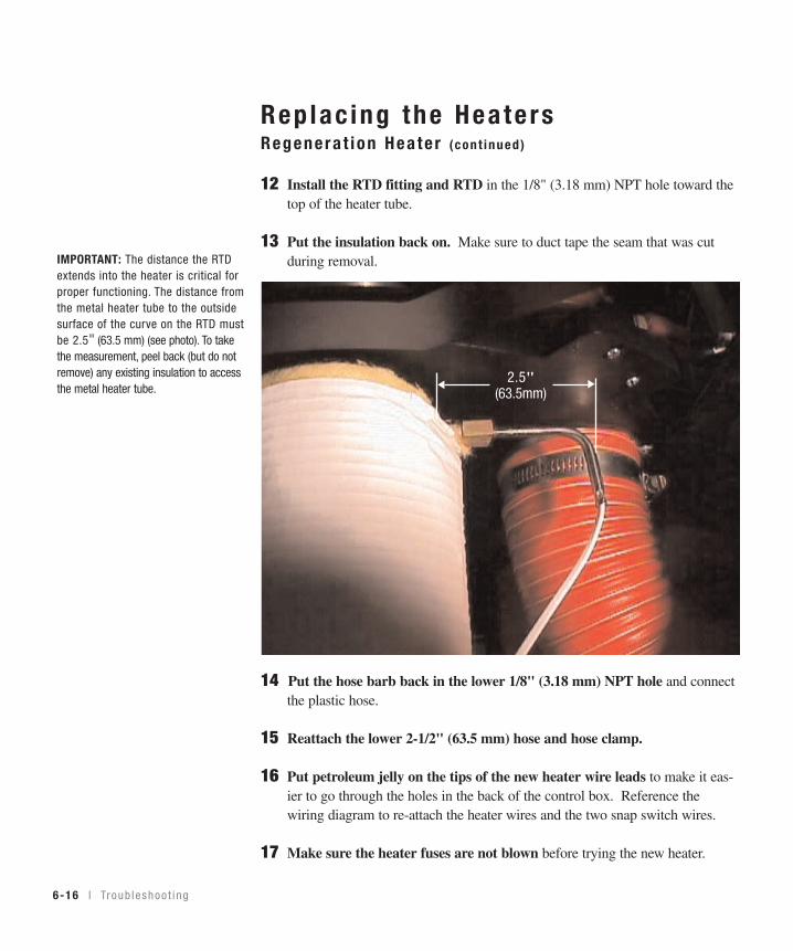
6-16 l Tr oub leshoo t i ng
Rep lac ing the Hea te rsRegenera t ion Hea te r (cont inued)
12 Install the RTD fitting and RTD in the 1/8" (3.18 mm) NPT hole toward thetop of the heater tube.
13 Put the insulation back on. Make sure to duct tape the seam that was cut during removal.
14 Put the hose barb back in the lower 1/8" (3.18 mm) NPT hole and connectthe plastic hose.
15 Reattach the lower 2-1/2" (63.5 mm) hose and hose clamp.
16 Put petroleum jelly on the tips of the new heater wire leads to make it eas-ier to go through the holes in the back of the control box. Reference thewiring diagram to re-attach the heater wires and the two snap switch wires.
17 Make sure the heater fuses are not blown before trying the new heater.
2.5"(63.5mm)
IMPORTANT: The distance the RTDextends into the heater is critical forproper functioning. The distance fromthe metal heater tube to the outsidesurface of the curve on the RTD mustbe 2.5" (63.5 mm) (see photo). To takethe measurement, peel back (but do notremove) any existing insulation to accessthe metal heater tube.

Troub leshoo t i ng l 6-17
✐
6Troubleshooting
Rep lac ing the Hea te r Process Hea te r
1 Disconnect and lockout the main powerat the main power source.
2 Open the electrical enclosure door.
3 Reference the wiring diagram and / or trace the wires from the processheater tube into the control box. Remove the wires from the relays and ter-minal strips. Once disconnected, pull the wires from the control box intothe dryer housing toward the heater tube.
4 Gain access to the process heater by removing the left dryer sidepanel.
For D15, D25, and D50 Dryers
5 Remove the hose and hose clamp at the bottom of the heater tube.
6 Remove the insulation from the heater tube by cutting the insulation in astraight line from top to bottom.
7 Remove the plugs or hose fittings toward the top end of the heater. These will need to be installed on the new heater.
8 Remove the heater tube by twisting the tube counterclockwise. Thetube is threaded into the lower bed plate. You may need to use a pipewrench or chain wrench to remove the heater.
9 Check the ID mark on the side of the heater tube for kW rating and volt-age. The ID mark is on the outside of the tube near the end with the leadwires. Make sure the kW and voltage is the same as the replacement heater.
10 Thread the new heater into the lower bed plate. The lead wires shouldbe pointing toward the inside of the dryer. Do not over tighten. Hand tight-en then use a wrench for no more than one turn to put the lead wires intothe correct position.
11 Put the insulation back on. Make sure to duct tape the seam that was cut during removal.
✒TIP: Depending on the model and
the mounting configuration selected
for the dryer installation, it may be
necessary to access the process
heater through the right side panel
or to remove the process blower to
create adequate access to use a
wrench to remove the process
heater. See Removing the Process
Blower.
Note: When installed,the process heatertube must be orientedso the power wires aretoward the inside ofthe dryer.

12 Reinstall the plugs or hose fittings into the holes near the top end of theheater tube.
13 Reattach the lower 2-1/2" (63.5 mm) hose and hose clamp.
14 Put petroleum jelly on the tips of the new heater wire leads to make iteasier to go through the holes in the back of the control box. Reference thewiring diagram to reattach the heater wires and the two snap switch wires.
15 Make sure the heater fuses are not blown before trying the new heater.
For D75 and D100 Dryers
5 Remove the hose clamp holding the heater tube to the dryer frame.
6 Remove the insulation from the heater tube by cutting the insulation in a straight line from top to bottom.
7 Remove the hose and clamps at the top and bottom of the heater tube.
8 Remove the plugs or hose fittings toward the top end of the heater. These will need to be installed on the new heater.
9 Remove the heater from the dryer.
10 Check the ID on the side of the heater tube for kW rating and voltage.The ID mark on the outside of the tube near the end with the lead wires.Make sure the kW and voltage is the same as the replacement heater.
11 Insert the heater in the dryer.
12 Reinstall the plugs or hose fittings toward the top of the heater tube.
13 Reattach the lower 2-1/2" (63.5 mm) hose and clamps to the top and bottom.
14 Put the insulation back on. Make sure to duct tape the seam that was cut during removal.
15 Install the hose clamp holding the heater tube to the dryer frame.
16 Put petroleum jelly on the tips of the new heater wire leads to make iteasier to go through the holes in the back of the control box. Reference thewiring diagram to reattach the heater wires and the two snap switch wires.
17 Make sure the heater fuses are not blown before trying the new heater.6-18 l Tr oub leshoo t i ng
Rep lac ing the Hea te r Process Hea te r ( con t i nued )

Troub leshoo t i ng l 6-19
6Troubleshooting
Rep lac ing the Des iccant Tanks
The D Carousel Dryer has refillable desiccant tanks. When desiccant becomesclogged or contaminated, you should replace the desiccant in all three tanks toensure optimum performance, or purchase new, prefilled tanks from Conair.
1 Stop the dryer then disconnect andlockout the main power.
2 Remove both side panelsfrom the dryer.
3 Disconnect the hose from the desic-cant tank. Loosen the hose clamp witha screw driver.
4 Lift the tank off the carousel assem-bly. If using new, proceed to #7.
5 Refill the tank with fresh desiccant.See “Refilling the Desiccant Tank(Section 6).
6 Check the O-rings in the carousel coupling. Replace any O-rings that arecracked, worn, or damaged. Apply petroleum jelly on the inside of the cou-pling around the O-ring.
7 Place the refilled tank on the carousel assembly. Make sure the inlet/outlettube of the tank seats fully into the O-rings on the carousel pipe.
8 Connect the hose to the top of the tank. Secure with the hose clamp.
9 Reinstall the side panel.
IMPORTANT: It’s important that the newtanks are connected to the correct hoses. Mark the hoses as theyare disconnected, or replace one tank ata time, to ensure that you install the newtanks in the correct positions.

6-20 l Tr oub leshoo t i ng
Ref i l l i ng the Des iccant TanksWhen desiccant becomes clogged or contaminated, you should replace the des-iccant in all three tanks to ensure optimum performance.
1 Remove the desiccant tank from the carousel. See “Replacing Desiccant Tanks.”
2 Remove the tank end plate.Remove the six 10-32 self-tapping screws from the end plate.
3 Remove the screen cap. Remove the two 1/4-20 nuts from the center post and pull the screen cap out.
4 Remove the old desiccant.
5 Replace the gasket on the flange, if necessary.
6 Fill the tank with fresh desiccant. Fill the tank with the weight of desiccant indicated in the following table.
Model Desiccant Weight15 & 25 1 lb. (0.37 kg)
50 2 lb. (0.75 kg)
75 3 lb. (1.12 kg)
100 4 lb. (1.49 kg)
(continued)
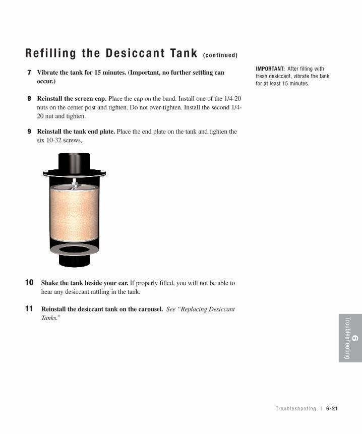
Troub leshoo t i ng l 6-21
6Troubleshooting
Ref i l l i ng the Des iccant Tank (cont inued)
7 Vibrate the tank for 15 minutes. (Important, no further settling canoccur.)
8 Reinstall the screen cap. Place the cap on the band. Install one of the 1/4-20nuts on the center post and tighten. Do not over-tighten. Install the second 1/4-20 nut and tighten.
9 Reinstall the tank end plate. Place the end plate on the tank and tighten thesix 10-32 screws.
10 Shake the tank beside your ear. If properly filled, you will not be able to hear any desiccant rattling in the tank.
11 Reinstall the desiccant tank on the carousel. See “Replacing Desiccant Tanks.”
IMPORTANT: After filling withfresh desiccant, vibrate the tankfor at least 15 minutes.

6-22 l Tr oub leshoo t i ng

We’re Here to He lpConair has made the largest investment in customer support in the plastics indus-try. Our service experts are available to help with any problem you might haveinstalling and operating your equipment. Your Conair sales representative also can help analyze the nature of your problem, assuring that it did not result frommisapplication or improper use.
How to Contac t Cus tomer Ser v iceTo contact Customer Service personnel, call:
From outsidethe United States, call: 814-437-6861
You can commission Conair service personnel to provide on-site service by con-tacting the Customer Service Department. Standard rates include an on-site hourlyrate, with a one-day minimum plus expenses.
Before You Ca l l . . .If you do have a problem, please complete the following checklist before calling Conair:
❒ Make sure you have all model, control type from the serial tag, and parts listnumbers for your particular equipment. Service personnel will need this infor-mation to assist you.
❒ Make sure power is supplied to the equipment.
❒ Make sure that all connectors and wires within and between control systemsand related components have been installed correctly.
❒ Check the troubleshooting guide of this manual for a solution.
❒ Thoroughly examine the instruction manual(s) for associated equipment, especial-ly controls. Each manual may have its own troubleshooting guide to help you.
❒ Check that the equipment has been operated as described in this manual.
❒ Check accompanying schematic drawings for information on special considerations.
Additional manuals and prints foryour Conair equipment may beordered through the CustomerService or Parts Department for anominal fee.
A ppend i x l A-1
A-2 l A ppend i x
Equ ipment Guaran teeConair guarantees the machinery and equipment on this order, for a period asdefined in the quotation from date of shipment, against defects in material andworkmanship under the normal use and service for which it was recommended(except for parts that are typically replaced after normal usage, such as filters,liner plates, etc.). Conair’s guarantee is limited to replacing, at our option, the partor parts determined by us to be defective after examination. The customer assumesthe cost of transportation of the part or parts to and from the factory.
Per fo rmance War ran tyConair warrants that this equipment will perform at or above the ratings stated inspecific quotations covering the equipment or as detailed in engineering specifica-tions, provided the equipment is applied, installed, operated and maintained in therecommended manner as outlined in our quotation or specifications.
Should performance not meet warranted levels, Conair at its discretion will exercise one of the following options:
• Inspect the equipment and perform alterations or adjustments to satisfy performance claims. (Charges for such inspections and corrections will bewaived unless failure to meet warranty is due to misapplication, improper installation, poor maintenance practices or improper operation.)
• Replace the original equipment with other Conair equipment that will meet original performance claims at no extra cost to the customer.
• Refund the invoiced cost to the customer. Credit is subject to prior notice by thecustomer at which time a Return Goods Authorization Number (RGA) will beissued by Conair’s Service Department. Returned equipment must be well cratedand in proper operating condition, including all parts. Returns must be prepaid.
Purchaser must notify Conair in writing of any claim and provide a customer receiptand other evidence that a claim is being made.
Warranty L imi ta t ionsExcept for the Equipment Guarantee and Performance Warranty statedabove, Conair disclaims all other warranties with respect to the equipment,express or implied, arising by operation of law, course of dealing, usage oftrade or otherwise, including but not limited to the implied warranties ofmerchantability and fitness for a particular purpose.

A ppend i x l B-1
Mount ing the Dr yer on a F loorS tand
Caution: to prevent accident and injury, lift the dryer onto the floor stand using a hoistand lifting lugs provided.
1 Lift the dryer onto the floor stand. Lift using a hoist and the lifting lugs pro-vided.
2 Align the four bolt holes on the bottom of the dryer with the four bolts holeson the top of the floor stand.
3 Bolt the dryer to the stand using the four 5/16”-18 bolts provided.
Tools for installation:
❒ 3/8” and 9/16”wrench
❒ Hoist

B-2 l A ppend i x
Mount ing the Dr yer and Hopper ona Mob i le F loor S tand
CAUTION: To prevent accident and injury, lift the empty hopper and the dryer ontothe mobile floor stand using a hoist and the lifting lugs provided.
1 Lift the hopper onto the mobile floor stand using a hoist and the lifting lugsprovided. Make sure you align the bolt holes in the mobile floor stand with thebolt holes on the discharge assembly.
(continued)
Tools for installation:❒ 5/32” Allen wrench❒ 3/8” and 9/16” wrench❒ Phillips screwdriver❒ Flathead screwdriver❒ Hoist and strap
A ppend i x l B-3
3 Lift the dryer onto the mobile floor stand using a hoist and lifting lugs provided.
4 Align the four bolt holes on the bottom ofthe dryer with the four bolts holes in themobile floor stand stand.
5 Bolt the dryer to the mobile floor standusing the four 5/16”-18 self-locking bolts provided.
Mount ing the Dr yer and Hopper on aMob i le F loor S tand (cont inued)
2 Bolt the hopper to the mobile floor stand.Using four 3/8”-16 (M 10) self-locking bolts,fasten the hopper to the mobile floor stand.

I ns ta l l i ng an A f te rcoo le r (Opt iona l )
You can add an aftercooler to the D Carousel Dryer by ordering the optional after-cooler assembly. Installation is easy.
The optional aftercooler requires a source of city, tower, or chiller water and a dis-charge or return line. You can use water at temperatures up to 85°F (30°C). But thewater flow should be at least 1 gal/min (3.8 liters/min) for models D15, D25, D50;or 2 gal/min (7.6 liters/min) for models D75 and D100.
1 Stop the dryer and lockout the main power.
2 Remove the cover plate from the right side of the aftercooler housing on thedryer by removing the five nuts.
3 Inspect the condition of the gasket. If the gasket is damaged, replace the gasket.
4 Insert the aftercooler assembly into the aftercooler housing. Make sure thestaggered holes in the aftercooler mounting plate align with the holes in theaftercooler housing.
(continued)C-1 l A ppend i x
✒TIP: Make the water supply and dis
charge / return connections with
flexible hoses at least 24 in. (61 cm)
long. This allows you to easily
remove the aftercooler assembly for
cleaning.

A ppend i x l C-2
I ns ta l l i ng an A f te rcoo le r (Opt iona l )(continued)
5 Secure the aftercooler assembly in the aftercooler housing using the fivescrews.
6 Connect the water supply line to the aftercooler inlet. If a manual shut offvalve is used, it should be mounted on the inlet line.
7 Connect the water discharge or return line to the aftercooler outlet.
8 Install the plastic aftercooler cap over the water connections, using the nutsremoved in step 2.

Clean ing the A f te rcoo le rIf you have the optional aftercooler, you need to clean the aftercooler coilsto keep them working efficiently. Cleaning frequency depends on the typeand amount of material you process.
1 Stop the dryer and lockout the main power.
2 Turn off the water flow to the water supply line. Disconnect supplyand return lines.
3 Remove the plastic aftercooler cover.
4 Remove the five nuts securing the aftercooler in the aftercoolerhousing.
✒TIP: If the aftercooler (without a flow control) was installed using the recommended 24 in.
(61 cm) of flexible hoses, there is no need to disconnect the hoses from the aftercooler
inlet and outlet unless they are taking it to another location for cleaning.
(continued)
C-3 l A ppend i x

A ppend i x l C-4
C lean ing the A f te rcoo le r (cont inued)
5 Remove the aftercooler assembly from the aftercooler housing.
6 Clean the aftercooler assembly using a mild soap and water. Let the after-cooler dry thoroughly before installation.
CAUTION: During the cleaning process, DO NOT cut or remove the stainlesssteel wire that holds the aftercooler assembly together.
7 Inspect the condition of the gasket. If it is damaged, replace the gasket.
8 Reassemble by repeating the steps in reverse order.
(continued)

Clean ing the A f te rcoo le r (cont inued)
9 Connect the water supply line to the aftercooler / precooler inlet. If a manualshut off valve is used, it should be mounted on the inlet line as well.
10 Connect the outlet of the aftercooler / precooler to the inlet of the flow controlvalve using the pre-shaped copper tubing and compression fittings provided.
11 Install the plastic aftercooler/precooler cover.
C-5 l A ppend i x

A ppend i x l D-1
I ns ta l l i ng a P recoo le r (Opt iona l )
You can add a precooler to the D Carousel Dryer by ordering the optional precool-er assembly. Installation is easy.
The optional precooler requires a source of city, tower, or chiller water and a dis-charge or return line. You can use water at temperatures up to 85°F ( 30°C). Butthe water flow should be at least 1 gal/min (3.8 liters/min) for models D15, D25,D50; or 2 gal/min (7.6 liters/min) for models D75 and D100.
1 Stop the dryer and lockout the main power.
2 Remove the left dryer side panel.
3 Mount the precooler to the back of the dryer using existingholes and the 5/16-8 bolts provided. Note that for D 15, 25,and 50 models, the precooler is mounted to the dryer with thewater fittings and precooler air outlet at the top. On D 75 and100 models, the precooler is mounted with the water fittings and precooler airoutlet at the bottom.
4 Connect the process air outlet hose to the precooler air inlet tube and tight-en the clamp provided.
5 Connect the hopper air inlet air hose to the precooler air outlet tube andtighten the clamp provided.
Note: It is strongly recommended that a customer-supplied manual flow control valvebe installed on the water inlet line.
6 Connect the water supply line to the precooler inlet. If a manual shut offvalve is used, it should be mounted on the inlet line.
(continued)
✐✒TIP: Make the water supply
and discharge / return
connections with flexible
hoses at least 24 in. (61cm)
long. This allows you to
easily remove the precooler
assembly for cleaning.
D-2 l A ppend i x
I ns ta l l i ng a P recoo le r (Opt iona l )(continued)
7 Connect the water discharge or return line with the pressure relief valve tothe precooler outlet. Use the bracket supplied to secure the pressure reliefvalve and discharge line to the back of the dryer.
8 Install the plastic precooler cap over the water connections.
Precooler installed on a D 15, 25,and 50 dryer without a flow control
Precooler installed on a D 75 and100 dryer without a flow control
IMPORTANT: For drying setpoint
temperatures above 150°F
(65.6°C), the precooler must be
bypassed by connecting the dryer
supply hose from the dryer
directly to the hopper inlet.

A ppend i x l D-3
C lean ing the P recoo le r If you have the optional precooler, you need to clean the precooler coils to keepthem working efficiently. Cleaning frequency depends on the type and amount ofmaterial you process.
1 Stop the dryer and lockout the mainpower.
2 Turn off the water flow to the watersupply line. Disconnect supply and returnlines.
3 Remove the plastic precooler cover.
4 Remove the five screws securing the precooler assembly in the precoolerhousing.
(continued)

D-4 l A ppend i x
5 Remove the precooler assembly from the precooler housing.
6 Clean the precooler assembly using a mild soap and water. Let the precoolerdry thoroughly before installation.
CAUTION: During the cleaning process, DO NOT cut or remove the stainless steelwire that holds the precooler assembly together.
7 Inspect the condition of the gasket. If the gasket is damaged, replace the gasket.
8 Reassemble by repeating the steps in reverse order.
Clean ing the P recoo le r (cont inued)