d. sinČiĆ et al., novel fouling measurement device, chem
TRANSCRIPT
D. SINČIĆ et al., Novel Fouling Measurement Device, Chem. Biochem. Eng. Q., 28 (4) 465–472 (2014) 465
Introduction
During processing, refinery hydrocarbons are heated up usually to temperatures from 250 to 550 °C. This causes the development of various pro-cesses resulting in a deposit adhering to the walls of the processing equipment. The fouling of process units walls diminishes the heat transfer significantly making it the major problem in the petrochemical industry1. When the decrease in heat transfer effi-ciency becomes so severe that the required tempera-ture cannot be reached, the operation must be stopped and the equipment cleaned. This causes ex-penses which are quite high as has been document-ed in the literature2,3. For that reason, the research activity concerning various aspects of that phenom-enon is noteworthy as may be inferred from several recent literature reports. The magnitude of the prob-lem appears to be highest in crude oil distillation units, so that the majority of the reports are dealing with crude oil fouling properties4,5,6.
There are various causes and mechanisms of fouling formation and they are discussed in numer-ous literature references7,8,9,10 in which other aspects of fouling phenomenon have been analyzed also.
In any case, the monitoring of the fouling pro-cess is an important technical problem, and various approaches and instruments have been proposed8,11. Three groups of instruments may be singled out:
1. Small scale heat exchangers that are actually replicas of the industrial equipment. They require an
appreciable amount of liquid. The extensive time for achieving conditions where heat transfer characteris-tics alteration appears as a consequence of fouling pro-cesses is the main reason why a considerable amount of total time is needed to achieve useful results;
2. Autoclaves – there are two possible con-structions:
a. Cylindrical heated probe upward mounted on the bottom of the vessel around which stirred liquid circulates12;
b. Heated probe mounted vertically in the ves-sel with liquid flowing alongside13. The flow is in-duced by the helical impeller positioned above the probe.
3. Hot-wire instruments14. The wall of the pro-cess equipment is simulated by the hot wire. There are various instrument types currently in use in lab-oratory practice.
Construction of the new device
The basic idea behind the construction of the new apparatus was to have an instrument which would be more suitable for extensive experimenta-tion without spending too much test liquid, and which would enable the fouling effects to show up in relatively short time. The simplicity of the con-struction was an important goal as well. After con-structing several models, which were examined from various aspects, the one schematically present-ed in Figure 1 was selected as the final design. The construction details have been elaborated else-where15.
Novel Fouling Measurement Device
D. Sinčić,a,* B. Ribić,a,+ and A. Caharijab
aKemprojekt, Zagreb City Holding, Zagreb, CroatiabFaculty of Chemical Engineering and Technology, University of Zagreb, Zagreb, Croatia
The novel device for measuring characteristics of the process that takes place when hydrocarbon liquids are subjected to elevated temperatures is described. The measuring cell has the form of a loop in which circulation is induced by a turbine stirrer. The stirrer contains magnets built into its blades, enabling mixing by a magnetic mixer positioned below the cell. No moving part protrudes from the cell. The fouling process takes place at the hot-wire probe positioned at the centre of the liquid stream. Thermo-graphic imag-es of the cell with circulating liquid are used to establish the type of the flow within the cell. The tests were performed with various types of liquids and versatility of the device demonstrated.
Key words:fouling, fouling probe, hot-wire fouling probe, furfural fouling
+ Current adress: Zagreb City Holding, Zagreb
* Corresponding author: [email protected]
doi: 10.15255/CABEQ.2014.1933
Original scientific paper Received: February 18, 2014
Accepted: November 20, 2014
466 D. SINČIĆ et al., Novel Fouling Measurement Device, Chem. Biochem. Eng. Q., 28 (4) 465–472 (2014)
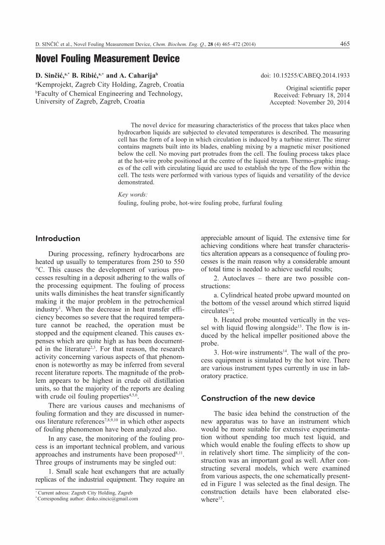
The cell is of much smaller volume than pre-vious designs (about 100 mL) with main dimen-sions given in Figure 1. It is situated in the air bath thermostat allowing temperature adjustment of its wall and the liquid inside to a desired level in the range 20–200 °C. The probe is made of glass or metal, depending on the conditions in which the experiments are to be carried out. It has a loop form. The circulation of the liquid is maintained by a magnetic stirrer in the form of a turbine. The im-peller contains strong magnets, which are in a particular way incorporated into its blades. The magnets were specially designed for this purpose and made from SmCo material. This type of mag-net is very resistant to temperature and corrosion. The stirrer revolves around the shaft fixed to the metal cap of the socket 1 (S1 on the Figure 1). Mixing is performed by the outside magnetic stir-rer so that no moving part protrudes from the de-vice. This facilitates its sealing so that working un-der pressure or inert atmosphere is easily carried out.
The second socket (S2) on the test cell is fore-seen for installing the hot-wire measuring probe. The titanium or platinum wire, 0.125 mm in dia-meter and approx. 20 mm long, is fixed at four points and connected to copper wires (2 mm in di-ameter) through which the direct current is supplied from the appropriate source. The outer wires are connected to the power source, while the inner two serve for voltage drop measurements. This way, the transition resistance problem is avoided and wire temperature may be accurately determined. The transition resistance in certain hot-wire measuring probes is determined indirectly, which diminishes the accuracy of the measurement. The temperature
of the testing medium is measured by the ther-mocouples in front and after the liquid passes the wire.
Measurement system setup description
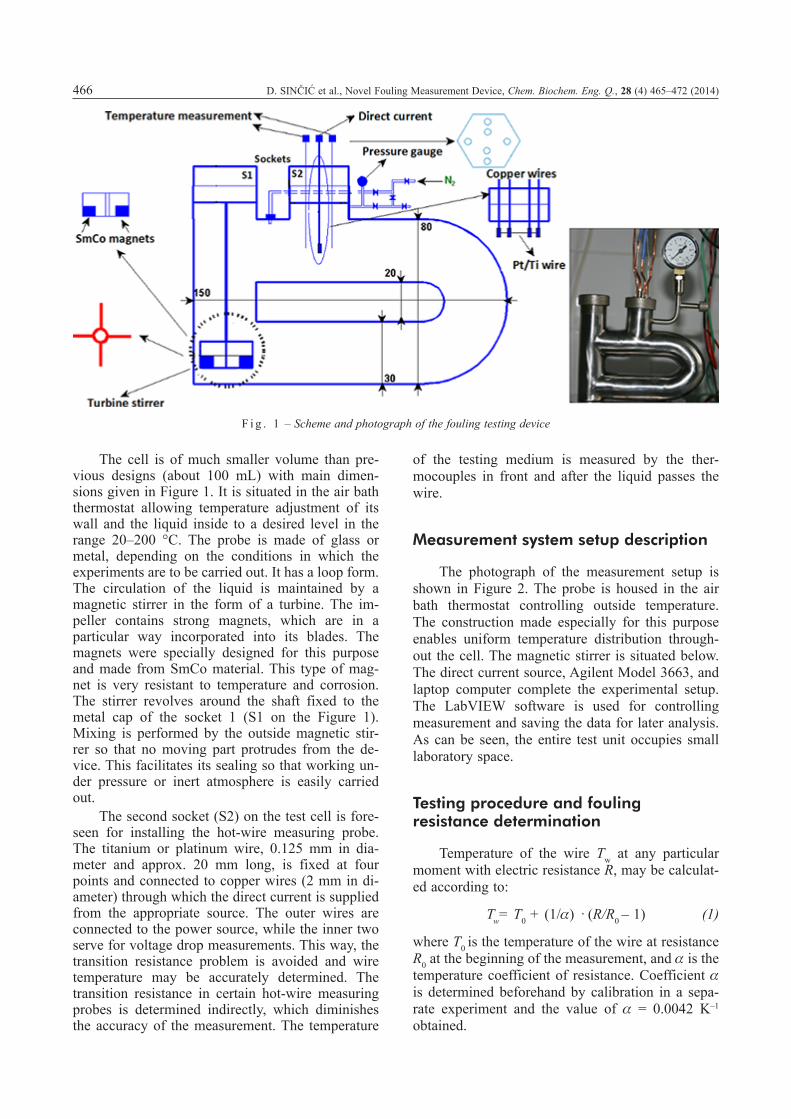
The photograph of the measurement setup is shown in Figure 2. The probe is housed in the air bath thermostat controlling outside temperature. The construction made especially for this purpose enables uniform temperature distribution through-out the cell. The magnetic stirrer is situated below. The direct current source, Agilent Model 3663, and laptop computer complete the experimental setup. The LabVIEW software is used for controlling measurement and saving the data for later analysis. As can be seen, the entire test unit occupies small laboratory space.
Testing procedure and fouling resistance determination
Temperature of the wire Tw at any particular moment with electric resistance R, may be calculat-ed according to:
Tw= T0 + (1/a) · (R/R0 – 1) (1)
where T0 is the temperature of the wire at resistance R0 at the beginning of the measurement, and a is the temperature coefficient of resistance. Coefficient a is determined beforehand by calibration in a sepa-rate experiment and the value of a = 0.0042 K–1 obtained.
F i g . 1 – Scheme and photograph of the fouling testing device

D. SINČIĆ et al., Novel Fouling Measurement Device, Chem. Biochem. Eng. Q., 28 (4) 465–472 (2014) 467
Following Fetissov et al.14 subsequent relations apply:
The heat quantity Q developed in the wire through which the current of strength I flows is:
Q = I2· R (2)
Coefficient of the heat transfer may be calculat-ed by well-known relations:
h0= (Q/A) · (T0 – Tk) at the beginning of the measurement, (3)
h = (Q/A) · (Tw – Tk) at any other moment, (4)
where Tk is the bulk temperature of the test liquid, and A is the area of the heat transfer surface. The heat transfer coefficient depends on the Reynolds and Prandtl numbers, h = f(Re,Pr) so that thorough investigations must be performed at different flow velocities.
Resistance to heat transfer at a particular mo-ment as the result of wire fouling, Rf corresponds to the difference in coefficients in clean and fouled state:
Rf = (1/h) – (1/h0). (5)
Assuming that heat-transfer convective coeffi-cients are independent of wire-diameter changes, characteristics of its surface, and assuming that there is no change in the properties of the liquid tested, and that aggregate state of the substance is unchanged, resistance to heat transfer may be calcu-lated according to:
Rf = [(Tw – T0)/Q +1/h0 A – 1/h Af] ·Alm (6)
where A is the surface of the clean wire, Af is the surface area of the fouled wire, and Alm is the loga-rithmic mean of these two surfaces. Expression (6) may be simplified14 to:
Rf = [(Tw – T0) /Q] · A (m2 K W–1). (7)
Measurements start by establishing resistance R0 at temperature T0. After starting stirring, the cur-rent strength corresponding to the desired wire tem-perature is set. The stirring rate is selected based on the stirring rate vs. flow rate relationship. This rela-tionship was attempted to be determined in two ways. First, a Doppler effect based instrument was used. However, no reproducible results were ob-tained. For that reason geometrically similar glass cell and solid trace particles were used instead, and the flow characteristics recorded by video camera. With the help of Adobe Premier software, the flow rate was estimated. The stirring rate was varied from 1.7 to 7.5 s–1, resulting in superficial liquid ve-locity in the range of 0.3 – 0.15 m s–1 corresponding to Reynolds numbers of 850 to 4200. At stirring rate of n = 5 s–1 (300 rpm), the Reynolds number for the liquid flow inside the cell was estimated to be approximately 2700.
Temperature distributions inside the cell
The cell in which the measurements presented further were performed is made of grade 316 stain-less steel. Temperature distributions inside the cell were carefully examined. First, five thermocouples were evenly and horizontally positioned across the cell, starting from the position close to the left wall. The measurements were performed continuously at
F i g . 2 – Photograph of the complete test unit

468 D. SINČIĆ et al., Novel Fouling Measurement Device, Chem. Biochem. Eng. Q., 28 (4) 465–472 (2014)
various wire temperatures and at n = 5 s–1 (300 rpm) stirring rate. As can be seen from Figure 3a, practi-cally no difference exists between the temperature values. The slight difference may be attributed to the thermocouple inherent precision properties rath-er than a temperature difference itself. Similarly, the thermocouples were positioned vertically across the cell. As can be seen from Figure 3b, again the re-corded values of the temperatures for all thermo-couples were very close. It may be concluded that a fully developed turbulent regime exists at n = 5 s–1
(300 rpm).Temperature distribution was examined by
thermographic camera as well. ThermaCAM PM695 model was used for that purpose. The results are shown in Figures 4a and 4b. In the case of stirring rate n = 5 s–1 (300 rpm), the photographs were tak-en 7 minutes apart. At n = 8.33 s–1 (500 rpm) ( Figure 4b), this difference was 5 minutes. It could be estimated that the uniform temperature distribution in the first case was achieved in about 20, while at higher stirring speed in about 5 min-utes.
Experimental results
In the tests performed, furfural was deaerated before testing (the condition strictly controlled in the industrial process), while other tests liquids were used as delivered.
First, the testing of the indene fouling be-haviour was undertaken. Indene is unsaturated hy-drocarbon, which has been used for this purpose before16. In order to avoid possible pronounced ef-fects, used was a 5 % indene solution (supplied by Sigma Aldrich, >99 % purity) in diesel fuel con-forming to EN 590 standard and produced by INA Croatian oil company. In order to differentiate be-tween contributions to deposit build-up of mixture constituents, first the pure diesel fuel was subjected to various wire temperatures. Regularly after some transition time, no change in wire temperature was observed, while the fouling resistance remained low (oscillating around 0.05 m2 K kW–1 ) indicating that no deposit build-up had occurred.
In the case of indene solution, initial tempera-ture of T0 = 132 °C sharply increased after 100 min-
F i g . 3 – a) Temperature profile of 5 centrally and horizontally positioned thermocouples; b) Temperature profile of 3 centrally and vertically positioned thermocouples

D. SINČIĆ et al., Novel Fouling Measurement Device, Chem. Biochem. Eng. Q., 28 (4) 465–472 (2014) 469
F i g . 4 – a) Dynamics of the temperature distribution in the cell.; n = 5 s–1 (300 min–1). Liquid: Diesel fuel. Wire temperature: 212 °C; b) Dynamics of the temperature distribution in the cell.; n = 8.33 s–1 (500 min–1). Liquid: Diesel fuel. Wire temperature: 212 °C

470 D. SINČIĆ et al., Novel Fouling Measurement Device, Chem. Biochem. Eng. Q., 28 (4) 465–472 (2014)
utes. The wire temperature reached 350 °C and the fouling resistance increased drastically as well, reaching the value of Rf,max = 0.490 m2 K kW–1 and indicating severe deposit build-up (Figure 5). In the beginning of this test, a decrease in fouling resis-tance appeared assuming negative values. Critten-den et al.7 explained this phenomenon as follows: As fouling layer initially starts to build it causes the surface to roughen with the effect that the local heat transfer increases. Thus the calculated fouling resis-tance may appear to become negative. As the foul-ing layer thickens the effect of the lower thermal conductivity overtakes the improved local heat transfer coefficient due to roughening and the foul-ing resistance becomes positive.
The next set of experiments was performed with an unsaturated hydrocarbon mixture obtained by deparaffination of vacuum distillate light frac-tion used in lubricating oil production in Mlaka Re-finery, Rijeka. The composition of that stream in the plant was varying appreciably due to frequent change of incoming oil origin and no analysis was available. We were asked to examine the fouling properties of that particular process stream, which in the plant was labeled as a Filtrate II.
The tests were performed by increasing initial temperature of the wire. At Tw,0 = 132 °C, there was no appreciable increase in wire temperature and the heat transfer coefficient decreased slightly. The fouling resistance increased slightly as well, reach-ing the value of 0.05 m2 K kW–1 . Further increase in initial temperature led to pronounced fouling. At Tw,0 = 181 °C, the Rf,max value of 0.062 was reached
– not so much higher than in the previous case – and wire temperature exceeded 140 °C.
At Tw,0 = 224 °C the temperature rise after 200 minutes began to increase noticeably, accompa-nied by a fouling resistance increase. The Rf,max of 0.133 m2 K kW–1 was reached.
The addition of one commercial antifoulant slowed down the wire temperature increase; howev-er, the fouling resistance surpassed the value reached in the case of no antifoulant addition (Figure 7).
The next set of experiments was performed with furfural, an important industrial chemical used
F i g . 5 – Temperature and fouling resistance profiles for the 5 % indene solution in diesel fuel at Tw,0 = 132 °C F i g . 6 – Temperature and fouling resistance profiles for Fil-
trate II at Tw,0 = 224 °C
F i g . 7 – Temperature and fouling resistance profiles for Fil-trate II at Tw,0 = 218 °C with the addition of 50 ppm of one commercial antifoulant

D. SINČIĆ et al., Novel Fouling Measurement Device, Chem. Biochem. Eng. Q., 28 (4) 465–472 (2014) 471
in lubricating oil processing for aromatics ex-traction. The used chemical was of industrial grade purity (furfural content > 98 %), deaeratad before testing. Starting with Tw,0 = 190.4 °C, a steady wire temperature increase was detected without any de-lay, which was noticed in most of the previous cas-es. Fouling resistance increase to a value of Rf = 0.5 m2 K kW–1 (Figure 8), reflects plant behaviour where fouling is a significant problem requiring ad-equate chemical treatment.
The typical antifoulant for this process contains antioxidants. In order to come up with a cheaper but yet efficient treatment, we made use of the fact that when the acid value of furfural is high its degrada-tion is appreciable. In other words, the addition of an appropriate chemical with basic characteristics may serve as antifoulant. The neutralizers contain-ing various simple amines are common chemicals in the petrochemical industry and for that reason the idea was tested by examining two typical ones. Morpholine was added first and temperature set at Tw,0 = 202 °C. The wire temperature showed only a slight increase, indicating pronounced effect in slowing down the fouling process.
The addition of the same type of chemical – methoxy propyl amine – exhibits interesting be-haviour. The temperature Tw,0 = 155.5 °C exceeded 200 °C in about 15 minutes and continued to rise to about 225 °C, when it stopped increasing further. Fouling resistance remained low, significantly low-er than in previous cases (Figure 9).
The temperature of about 200 °C, based on our numerous experiments, appears to be some kind of critical value for furfural. Once exceeded, it usually continues to increase, indicating that pronounced fouling is taking place.
Discussion
Reported fouling testing encompasses a wide variety of liquids and their specific compositions en-countered in petrochemical industry. For that reason direct comparison of the results obtained in specific measurements is practically impossible. One of the rare opportunities is the possibility of comparing the results for indene. Asomaning et al.16 present the re-sults of the fouling test of 10 % indene in kerosene. The value of Rf = 0.75 m2 K kW–1 was reached for air saturated indene. Here, the maximum value of 0.49 m2 K kW–1 was obtained with indene used as deliv-ered. When fouling of hexadecane–1 was tested, val-ues of Rf = 0.27 m2 K kW–1 and Rf = 0.19 m2 K kW–1
in annular and hot-wire probe were reported, demon-strating the difference of the results obtained when testing the same liquid with two different probes. Re-view of other available data may be summed up into the range of fouling resistances of 0.1 – 0.7 m2 K kW–1. This finding and all of the results presented here, show that this probe gave results that fall in line with the results of other researchers. In general, when comparing the results of different studies, two opin-ions should be taken into account. Sinquefield states17 that the skilled artisan can attest that significant variations may occur in fouling tests conducted in the same apparatus under the same conditions. Ea-ton12 says that it has generally been conceded by those experienced in this art that fouling tests usually reproduce the fouling rate by no more than 50 %. In many cases this makes the test useless in determining the effect of some independent variable, such as fluid composition, because the fouling rate changes more by itself than by changing the independent variable.
F i g . 8 – Temperature and fouling resistance profiles for fur-fural at Tw,0 = 190.4 °C
F i g . 9 – Temperature and fouling resistance profiles for fur-fural at Tw,0 = 155.5 °C with the addition of methoxy propyl amine

472 D. SINČIĆ et al., Novel Fouling Measurement Device, Chem. Biochem. Eng. Q., 28 (4) 465–472 (2014)
Conclusions
The test performed with the new device for fouling monitoring and antifoulant testing show that it can be successfully applied in the laboratory. Namely, it is shown that commercial antifoulants may not work as often suggested, so that testing be-fore application should help in preventing an inade-quate selection of chemicals and consequently caus-ing an increase rather than a decrease in equipment operating expenses. Millions of dollars are spent on purchasing chemicals based on the statements in tender accompanying documents without prior test-ing of their effectiveness. Any petrochemical labo-ratory could afford a simple device such as this, and perform its own tests in a very short time, resulting in confidence in proper chemical selection. That was the primary goal in undertaking the develop-ment of this novel device.
The testing of indene and the unsaturated hy-drocarbon mixture (Filtrate II), showed a certain delay in fouling build-up, while furfural does not exhibit that kind of behaviour. This fact points at different mechanisms of the fouling process in these two cases.
In particular, one result of practical importance should be pointed out: fouling in the important in-dustrial process of base oil preparation may be alle-viated by the addition of simple amines instead of devoted, usually expensive, chemicals.
ACKNOWLEDGEMENT
This research was supported by the grant from the Croatian Ministry of Science, Education and Sports, Project TP-03/125–25. The support is great-ly appreciated.
L i s t o f s y m b o l s
L a t i n l e t t e r s
A, Af, Alm – area of the heat transfer surface, clean, fouled, and mean, m2
h – heat transfer coefficient, W m–2 K–1
I – current, An – stirring rate, s–1, rpmQ – heat flow, WR – electrical resistance, ΩRf – fouling resistance, m2 K W–1
T,Tw – temperatures, °C, K
G r e e k l e t t e r s
a – temperature coefficient of electrical resistance, K–1
R e f e r e n c e s
1. Bot, T. R., Fouling of Heat Exchangers, Elsevier, Amster-dam, 1995.
2. Van Nostrand, W. L., Leach, S. H., Haluska, J. L., Economic Penalties Associated with the Fouling of Refinery Heat Transfer Equipment, in Somerscales, E. F. C. and Knudsen, J. G., (Eds.), Fouling of Heat Transfer Equipment, Hemi-sphere Publishing, Washington, 1981, p. 619.
3. Machietto, S., Hewit, G. F., Coletti, F., Crittenden, B. D., Dugwell, D. R., Galindo, A., Jackson, G., Kandyiopti, R., Ka-zarian, S. G., Luckham, P. F., Matar, O. K., Millan_Agorio, M., Mueller, E. A., Paterson, W., Pugh, S. J., Richardson, S. M., Wilson, D. J., in Müller-Steinhagen, H., Reza Malayeri, M. and Watkinson, A. P. (Eds.), Fouling in crude oil preheat trains: A systematic solution to an old problem, Proceedings of International Conference on Heat Exchanger Fouling and Cleaning, Schladming, Austria, 2009, pp. 1–14.
4. Bennett, C. A. Kistler, R. S., Nangia, K., Al-Ghawas, W., Al-Hajji, N., Al-Jemaz, A., Observation of an isokinetic tempera-ture and compensation effect for high temperature crude oil fouling, in Müller-Steinhagen, H., Reza Malayeri, M. and Watkinson, A. P. (Eds.), Proceedings of 7th International Con-ference on Heat Exchanger Fouling and Cleaning – Challeng-es and Opportunities, Tomar, Portugal, 2007, pp 32 – 42.
5. Young, A., Venditti, S., Berrueco, C., Yang, M., Waters, A., Davies, H., Hill, S., Millan, M., Crittenden, B. D., Character-ization of crude oils and their fouling deposits using a batch stirred cell system, Heat Transfer Engineering 32 (2011) 216.http://dx.doi.org/10.1080/01457632.2010.495603
6. Yang, M., O’Meara, A., Crittenden, B. D., Determination of crude oil fouling thresholds, in Reza Malayeri, M., Watkin-son, A. P., and Müller-Steinhagen, H. (Eds.), Proceedings of International Conference on Heat Exchanger Fouling and Cleaning, Crete Island, Greece, 2011, pp. 1–6.
7. Crittenden, B. D., Khater, E. M. H., Fouling in Hydrocar-bon Vapouriser, Chem. Eng. Symp. Ser. 86 (1984) 401.
8. Knudsen, J. G., Apparatus &Techniques for Measurement of Fouling of Heat Transfer Surfaces, in Somerscales, E. F. C. and Knudsen, J. G. (Eds.) Fouling of Heat Transfer Equip-ment, Hemisphere Publishing, Washington, 1981., pp. 58–81.
9. Taborek, J., Aoki, T., Ritter, R. B., Palen, J. W., Fouling: The Major Unresolved Problem in Heat Transfer, CEP 68 (1972) (2) 59.
10. Panchal, C. B., Watkinson, A. P., Chemical Reaction Foul-ing Model for Single-phase Heat Transfer, AIChE Symp. Ser. 89 (1993) 323..
11. Watkinson, P. A., Comparison of Crude Oil Fouling Using Two Different Probes, ECI Conference on Heat Exchanger Fouling and Cleaning, Santa Fe, 2004, pp. 234–240.
12. Eaton, P., Method and Apparatus for Conducting Fouling Tests, US Patent 4910999 (1990).
13. Panchal, C. B., Zhuoxiong, M., High Temperature Fouling Test Unit, US Patent 6,062,069 (2000).
14. Fetissov, P. E., Watkinson, A. P., Epstein, N., Comparison of Two Heat Transfer Fouling Probes, Proc. 7th Int. Heat Transfer Conf., Munich, 1982, pp. 391–396.
15. Sincic, D., Device for the measurement of thermal decom-position of hydrocarbons (in Croatian), Croatian Patent HR P20090689 A2, (2011).
16. Asomaning, S., Watkinson, P. A., Heat Exchanger Fouling by Olefin – Kerosene Mixture, Can. J. Chem. Eng. 70 (1992) 444.http://dx.doi.org/10.1002/cjce.5450700306
17. Sinquefield, S. A., Fouling test apparatus and process for evaluation of anti-foulants, US Patent 6,978,663 (2005).