damping and excitation in the torsional vibrations ... · ship propulsion systems ... implemented...
TRANSCRIPT
S – 165
Damping and excitation in the torsional vibrations calculation of
ship propulsion systems
Nenad Vulić
Faculty of Maritime Studies, University of Split, Croatia
Đorđe Dobrota
Faculty of Maritime Studies, University of Split, Croatia
Ivan Komar
Faculty of Maritime Studies, University of Split, Croatia
Abstract. Calculation of torsional vibrations is essential in the early phase of the design of any ship
propulsion system, after selection of shafting diameters in accordance with the Classification Rules.
Later on, during ship trials, the calculation shall be validated by measurements on board. The
calculation results depend upon inertial moments of actual masses, stiffness of shafting components,
damping in the actual shafting components, as well as the excitation forces and moments exerted by
the propulsion engine(s) and the propeller. Inertial moments and stiffness can be determined with no
ambiguities. However, this is not the case with either the damping, or the engine excitation. Actually,
during validation on board the calculation supposed damping is the main influential factor to be
verified. The aim of this paper is to present and compare several models to define and compare
damping definitions in the the torsional vibrations calculation (Frahm's model, Archer's model,
physical damping, magnification factor, etc.) in a systematic way, to enable designers to correctly
apply the selected damping model. Further on the engine excitation may be expressed by means of
cylinder pressures or tangential forces to the cranks. The essentials of the two models and the
procedure to convert one excitation model into another one are also presented. The application of the
presented damping and excitation models is presented on an actual ship propulsion system and
conclusions drawn.
Key words: marine shafting design, steady-state torsional vibration analysis, SimulationX, validation
by on-board measurements, acceptance criteria
1. Introduction
Designer of any ship propulsion system has the main goal from the very beginning: to select
the propeller that enables ship to achieve contracted speed for the given ship hull form, as
well as to select the proper main propulsion prime mover (e.g. Diesel engine, steam or gas
turbine plant and reduction gearbox) able to produce and transmit power to the main
propulsion shafting.
The next step is determination of design form, dimensions, material and service loading of the
shafting itself. Preliminary dimensions, i.e. external and internal diameters of particular shafts
may be easily determined on the basis of MCR power, relevant rotational speed and
mechanical properties of the selected material by implementing classification Rules. These
classification Rules are generally based upon IACS Unified Requirement UR M68,
comprising simple formulae applied to the calculation of these diameters.

S – 166
However, in this very first design phase it is very important do determine the shafting steady
state response to the engine and propeller variable torque excitation around the shafting axis,
i.e. torsional vibrations response. It is a difficult task in this phase, because the entire shafting
system has not been completely defined yet. Unfortunately, in case of improper design in this
phase, there is not much that can be done in later phases, other than providing and installing
the torsional vibration damper. For this reason, proper calculation of torsional vibration is
necessary in the initial phase of the marine shafting design.
In general, torsional vibrational response of shafting depends also upon its design form,
dimensions, material and service loading. The most appropriate model for the analysis of
shafting system torsional vibrations is the model with lumped masses (represented by their
mass moments of inertia around the shafting axes), massless shafts (representing stiffness and
damping of parts of the system) and engine loading.
Considering steady-state response in terms of angular, torque and stress amplitudes for
various shafting rotational speeds in the operational speed range the particular necessary data
to be provided are the mass moments of inertia for each concentrated mass, the torsional
stiffness of shafts, structural damping in the shafts, damping of propellers, flexible couplings
and torques due to cylinder pressures and inertial forces of the reciprocating parts of engine
systems for a single engine cycle (two-stroke or four stroke).
Evaluation of either mass moments of inertia for each lumped mass in the system, or stiffness
of every particular shaft element is not difficult and can be performed in a rather
straightforward non-ambiguous manner. Unfortunately this is not the case with the estimation
of damping for particular elements of the system. The damping may be defined in various
terms. In addition to this, the excitation engine torques may be defined in several different
ways: cylinder pressures or crank tangential forces, both in closed form or expressed by the
Fourier series coefficients.
For these reason this paper focusses on presenting several definitions of damping in the
torsional vibrations shafting model, the methods to convert among them, as well as the
definitions of excitation torques in the model and their origin. In addition to this, classification
societies (e.g. in [1] and [2]) require validation of the torsional response of the shafting system
by measurements on-board the first in the series of newly built ships. In case the results do not
match the 5 per cent margin difference, the calculations shall be run again. So, it is necessary
to have the proper reliable methodology for defining of element damping properties and
excitation forces readily available in the shafting numerical model.
2. Modelling of torsional vibrational damping
The torsional damping estimation is the most ambiguous for the marine shafting designers.
No designer can be completely confident whether the damping data introduced and
implemented in the torsional vibration calculations are correct, unless the calculation results
are validated by means of measurement on-board [3].
The damping is the effect tending to reduce the vibratory amplitude of any oscillating system.
Energy dissipation always accompanies damping itself. For the calculation of marine shafting
torsional vibrations the four main types of damping are important [3]:
– viscous damping;
– fluid damping;
– internal damping; and
– structural damping.
The cause of viscous damping is the energy loss occurring in lubricating liquid between the
system parts in relative motion. Viscous damping force is directly proportional to the relative

S – 167
velocity between the moving parts of the vibrating system. Viscous damping may be
considered as absolute (between the moving part and the non-moving environment) or relative
(between the two parts in relative motion) [3].
The cause of fluid damping is the dynamic interaction of propeller and surrounding water.
The cause of internal (material) damping is the mechanical energy dissipation within the
material of the shafting, material of flexible couplings, as well as within the torsional
vibration dampers. The cause of structural damping is the relative friction between the
shafting system elements that are in mutual contact [3].
Owing to the fact that only the linear viscous damping model enables a simplified analytical
calculation approach, all the remaining types of damping models are in practice transformed
to the equivalent viscous damping, as follows: fluid damping as absolute viscous damping,
internal and structural damping as relative viscous damping [3].
For the above stated reasons there exist several possibilities to define and enter damping data
in various torsional vibration calculation computer programs. The definitions of damping used
in the most important programs will therefore be presented here.
Program SimulationX, developed by ITI GmbH [4], Dresden uses the following approach.
Viscous damping torque amounts to:
wbTD
= [Nm] (1)
and the damping approach factor, B (in the expression: kBb= ) uses the following “rule of
thumb" to estimate the damping:
B = 0,005 ... 0,01 - damping in metallic materials (e.g., shafts)
B = 0,10 ... 0,25 - damping in highly elastic materials (e.g., rubber coupling elements)
B = 0,05 ... 0,15 - structural and contact damping (e.g., gear teeth contacts / toothing)
Relative damping (ratio of damping energy), ψ (nonlinear, frequency dependent)
bk
wpy 2= →
wpy k
b ×=2
(2)
Lehr’s damping factor, D
k
bD
24
wp
y== →
wk
Db ×= 2 (3)
where:
k – element linear stiffness, Nm/rad
b – element linear viscous damping, Nms/rad
ω – phase velocity of vibration, rad/s
In the program ShaftDesigner, developed by prof. Y. Batrak, the following damping
definitions are used (the denotations for the k, b and ω as specified above):
Ratio of damping energy, ψ
MQk
b ppe
ppk
wpy
24
1
22
2
2==
-==
×= (4)
where:
κ – non-dimensional damping factor

S – 168
Q – vibration magnifier
22222222
12
4141M
b
bkQ +=
+=
+=
+=
+=
ee
yyp
kk
ww
(5)
ε – percent of critical damping, %
MQk
b
2
1
12
1
422 2=
-====
pykw
e (6)
M – dynamic magnifier
ey
pkw 2
11
21 2 =-==== Qb
kM (7)
Program GTORSI, developed by MAN Diesel & Turbo, Copenhagen, uses the following
definitions:
- absolute torsional damping (in % of critical damping), ρθ [%]
- physical damping (between the actual and previous inertia), bθ [Nms/rad]
- percentage modal damping wrt. stiffness, ρinner
- resulting physical damping, kb inner
wr2
= [Nms/rad] (8)
For its importance, the damping of the propeller deserves to be presented separately,
regardless of the calculation program. Propeller damping may be presented by means of the
equivalent absolute viscous damping. Dimensional equations are generally implemented, so
the user is to take care about the units used.
Frahm’s propeller damping factor, DF (in practice: 2,9…3,7), is used to define the propeller
absolute damping (Frahm), bAp as follows:
p
p
Fp
p
F
p
p
FApn
PDn
n
PD
n
TDb w
ppp××÷
ø
öçè
æ×=××÷ø
öçè
æ×=××=3
0
0
3
3
0
0
2303030
kNms/rad (9)
Archer’s propeller damping factor DA (in practice: 25…35, based upon the open water
characteristics of the Wageningen B-propeller series) implements a similar approach as for
the Fram’s factor [3]:
p
p
Ap
p
A
p
p
AApn
PDn
n
PD
n
TDb w
pp××÷
ø
öçè
æ×=××÷ø
öçè
æ×=×=3
0
0
2
3
0
0 3030 kNms/rad (10)
Obviously:
p30
×=× FA DD (11)
In the above equations the following denotations have been used:
P0 – engine nominal rating power (MCR), kW
n0 – engine nominal speed at MCR, rpm
i – gearbox transmission ratio
i
nn p
0
0 = – propeller nominal speed, rpm (12)
30
p
p
n×=
pw – propeller angular velocity, rad/s (13)
S – 169
np – propeller speed, rpm
0
00
30
n
PT ×=
p– engine nominal torque, kNm (14)
00 TiTp ×= – propeller nominal torque, kNm (15)
3
0
0 ÷÷ø
öççè
æ=
p
p
n
nPP – propeller power curve, kW (16)
2
0
0 ÷÷ø
öççè
æ=
p
p
pn
nTT – propeller torque curve, kNm (17)
Other propeller damping definitions, such as Ker Wilson’s formula, Dien-Schwanecke’s
formula, as well as MAN Diesel & Turbo’s recommendation to set propeller damping as 5%
of the critical have been presented in detail in [3].
3. Modelling of engine excitation loading
The Diesel engine cylinder may be provided by the engine manufacturer expressed in various
forms:
a) actual cylinder pressures vs. crank angle in the range of either ±180° for two-stroke
engines, or ±360° for four-stroke engines;
b) crank forces in tangential (circumferential) direction vs. crank angle, originating also
from the combustion pressure in engine cylinders
c) crank forces in tangential (circumferential) direction in terms of Fourier series
coefficients (precisely trigonometric approximation coefficients for the orders of 1; 2;
3; … in case of two-stroke engines and orders of 0,5; 1,0; 1,5; 2; 2,5; … for four
stroke engines.
In practice it is often necessary to provide simple means to convert among these forms.
Harmonic analysis, i.e. expressing of cylinder pressure/crank force vs. crank angle in the
terms of trigonometric approximation coefficients, from (a) to (b) or to (c) above, is rather
easy, following the procedure for the approximate calculation of Fourier series coefficients by
e.g. their numerical integration. However, the reverse procedure, from (c) to (b) or to (a)
above, may be a tricky one. For this reason the Excel/VBA program S06HarmSynt has been
developed and will be shortly presented hereafter.
Program S06HarmSynt calculates tangential force, cylinder pressure and crank torque, all vs.
crank angle, for the two cases: case of gas normal firing and gas compression only (misfiring)
for 2-stroke and 4-stroke internal combustion engines, from the following input data: cylinder
bore diameter, ratio of crank radius and connecting rod length, crank radius and harmonic
cosine and sine components of Fourier series expansion of gas normal firing and gas
compression only tangential pressure values, given for orders 0,5; 1; 1,5; 2; … for 4-stroke
engines or orders 1; 2; 3; … for 2-stroke engines.
Program input data comprise the gas normal firing and misfiring N harmonic (cosine and
sine) components FTC and FTS expressed as: p= FT/ Acyl, where
FT – force in tangential direction, N
Acyl= p d2/4 – cylinder area, mm² (18)
S – 170
The calculation procedure can briefly be described as follows:
Crank angle range α in 2-stroke engines
00 360360 +££- a (19)
Crank angle range α in 4-stroke engines
00 180180 +££- a (20)
Ratio of crank radius to the connecting rod length
lr /=l (21)
Connecting rod angle
alb sinsin ×= (22)
Gas force (positive downwards)
4
2dpFgas
p×= (23)
Tangential force on the crank journal due to gas forces
( )b
bacos
sin +×= gasT FF (24)
Cylinder pressure from tangential force
( )( ) 0sin ;
sin
cos
42
¹++
×= baba
bp d
Fp T
(25)
(valid under condition: ( ) 0sin ¹+ ba , otherwise: linear interpolation for nearby values)
Trig. approximation for tangential forces
2sin
2cos
2,
1
,
0 aa kF
kF
FF kTS
N
k
kTC
T
T å=
++= (26)
for zero crank angle
å=
-=N
k
kTCT kFF1
,0 cos2 p (27)
Mean indicated pressure (numerical integration)
( ) aal
aalaa
a
a
dpp im ×÷÷ø
öççè
æ
-
×+ò
max
min
22,
sin1
cossinsin
2
1 (28)
The calculation example to illustrate the presented methodology for a two-stroke engine cylinder
excitation, where inertial forces are to be considered separately begins from the data presented in the
following table.

S – 171
Table 1 Input data for an actual engine excitation loading calculations
Engine licence: MAN B&W Type: 6S50MC-C, 9180 kW / 123 rpm
engine working cycle (two stroke-2, four stroke-4)
cycle= 2
cylinder bore
D= 500 mm
ratio of crank radius and connecting rod length
l= r/l= 0,4878
crank radius (half of piston stroke)
r= 1000 mm
Inertia Gas normal firing Total
Gas misfiring only [Nmm/mm3]
Order SIN COS SIN Ampl
COS SIN Ampl
0 A0= 1,2624064
A0comp= 0
1 0 0,762603 1,459809 -0,0003 0,1566
2 0 0,0092984 1,727643 -0,0016 0,2393
3 0 -0,234102 1,315507 -0,0009 0,2222
4 0 -0,277969 0,930338 0,0011 0,1672
5 0 -0,297135 0,600769 0,0006 0,1235
6 0 -0,230167 0,362201 0 0,0899
7 0 -0,1787 0,224368 0,0003 0,0644
8 0 -0,137667 0,1123 0,0004 0,0454
9 0 -0,085266 0,048867 0,0001 0,0319
10 0 -0,0569 0,0176 -0,0002 0,0226
11 0 -0,0326 -0,00943 0,0003 0,0154
12 0 -0,010833 -0,0175 0 0,0108
The calculated results have been presented in Figure 1.
Figure 1 Calculation results, cylinder pressure and crank torque vs. crank angle
4. Validation of calculation on-board
Torsional vibrations calculation shall be verified on-board the first ship in the series. The
most practical way is measurements by strain-gauges, connected into the full Wheatstone-
bridge, that are glued on the surface of the shafting part which can be easily accessible from
the machinery space (e.g. intermediate shaft). The strain-gauges measure strain, for the
various levels of shafting rpm. This strain is converted into torsional stress and finally the
S – 172
torsional stress vs. shafting curve is plotted. Looking into this graph easily reveals critical
speeds and maximal stress levels. In accordance with class Rules, measured critical speed
shall not differ to the calculated ones by more than 5%. A more detailed presentation of
measurement methods and interpretation of the results would be beyond the scope of this
paper.
5. Illustrative example of the torsional vibration calculation
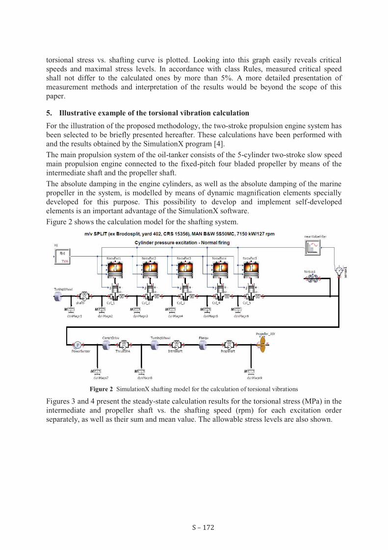
For the illustration of the proposed methodology, the two-stroke propulsion engine system has
been selected to be briefly presented hereafter. These calculations have been performed with
and the results obtained by the SimulationX program [4].
The main propulsion system of the oil-tanker consists of the 5-cylinder two-stroke slow speed
main propulsion engine connected to the fixed-pitch four bladed propeller by means of the
intermediate shaft and the propeller shaft.
The absolute damping in the engine cylinders, as well as the absolute damping of the marine
propeller in the system, is modelled by means of dynamic magnification elements specially
developed for this purpose. This possibility to develop and implement self-developed
elements is an important advantage of the SimulationX software.
Figure 2 shows the calculation model for the shafting system.
Figure 2 SimulationX shafting model for the calculation of torsional vibrations
Figures 3 and 4 present the steady-state calculation results for the torsional stress (MPa) in the
intermediate and propeller shaft vs. the shafting speed (rpm) for each excitation order
separately, as well as their sum and mean value. The allowable stress levels are also shown.

S – 173
Figure 3 Calculation results: torsional stress in the intermediate shaft
Figure 4 Calculation results: torsional stress in the propeller shaft
An important outcome of these analyses is that, for the particular ship in question, the
propulsion system continuous operation within the range of shafting rotational speed of about
60 rpm should be avoided (barred speed range), in order to decrease the possible damage to
the system due to resonance caused by excitation.
6. Conclusion
Torsional vibrations calculations are essential calculations which have to be performed in a
very early stage of the shafting design process, by means of an appropriate software program.

S – 174
The most difficult part in preparing data for these calculations, i.e. steady state response of the
system modelled by lumped mass and massless stiffness and damping elements is to define
damping and engine excitation in a proper way.
For this reason the methodology of definition of the damping implemented by several modern
software programs has been presented in such a way that particular values can be easily
converted from one to another and the results compared. This was the primary goal: to enable
user to select the damping model best fitted for the purpose of modelling the real system.
An additional goal was to present the approach to the calculation of engine excitation in other
forms (cylinder pressure vs. crank angle, or crank tangential force vs. crank angle), when
these are given in terms of trigonometric approximation (Fourier’s coefficients) for various
excitation orders. There are some tricky points in this approach, to which the attention has
been drawn.
Validation of the calculation results is essential, by measurements on-board, being the only
way to check out whether the damping and engine excitation has been correctly taken in the
calculations.
An illustrative example, showing the system and the obtained shafting torsional stress results
has been presented in the end, just to show the powerful possibilities of one of the calculation
programs intended for torsional vibration calculations (such as SimulationX).
REFERENCES
[1] UR M68 (2012), Dimensions of propulsion shafts and their permissible torsional vibration
stresses (Corr. 2, Nov. 2012), International Association of Classification Societies, London.
[2] CRS Rules (2013), Rules for the Classification of Ships, Part 7 - Machinery Installation,
Croatian Register of Shipping, Split.
[3] BATRAK, Y. (2011) Torsional vibration calculation issues with propulsion systems, Internet:
www.shaftdesigner.com, Retrieved 31.12.2011
[4] SimulationX Torsional Vibration Analysis (2013), in the SimulationX Library Manual, ITI
Software GmbH, Dresden.


CC OO NN FF EE RR EE NN CC EE PP RR OO CC EE EE DD II NN GG SS
PDF on USB stick with full papers
Publisher:
University of Split
University Department of Professional Studies
Kopilica 5
21000 Split, CROATIA
For the Publisher:
Šimun Anđelinović, Rector
Ado Matoković, Head
Editors-in-chief:
Bože Plazibat Silvana Kosanović
Cover Design:
Jašo Vrdoljak
Text Editor:
Josipa Mihovilović, Jašo Vrdoljak
Edition:
200 copies
CIP - Katalogizacija u publikaciji
S V E U Č I L I Š N A K N J I Ž N I C A U S P L I T U
UDK 33(063)
62(063)
INTERNATIONAL Scientific and Professional Conference Contemporary issues
in economy and technology (<2> ; 2016 ; Split)
Conference proceedings / International Scientific and Professional Conference
Contemporary issues in economy and technology, CIET 2016, Split, 16-18 June ;
<editors Bože Plazibat, Silvana Kosanović>. - Split :
University of Split, University Department of Professional Studies, 2016.
Publikacija u formatu PDF; sadrži 850 str. - Bibliografija.
ISBN 978-953-7220-25-9
I. Ekonomija -- Zbornik II. Tehnologija – Zbornik 160529054
CopyrightÓ University of Split, University Department of Professional Studies, Split, 2016 All rights reserved. No part of this publication may be reproduced, stored in retrieval system, or transmitted in any form or by any means, electronic, mechanical, photocopying, recording or otherwise, without the prior permission of the University of Split, University Department of Professional Studies.

ORGANISING COMMITTEE
Bože Plazibat, predsjednik OO-a
Anita Krolo Crvelin Mirko Gugić
Antonija Babić Nada Roguljić
Daniel Gherasim (ROU) Nicoleta Botez (ROU)
Domagoja Buljan Barbača Radu Florea (ROU)
Goran Ćorluka Sergej Lugoivć
Ivica Ružić Silvana Kosanović
Jašo Vrdoljak Siniša Zorica
Karmen Klarin Slavica Ćosović Bajić
Lada Reić Tonko Kovačević
Larisa Savga (MDA) Zlatko Jankoski
SCIENTIFIC COMMITTEE
Ana Goncalves (ESP) Igor Nazor (HRV) Rino Lucić (HRV)
Andreea Oana Iacobuta (ROU) Ivana Plazibat (HRV) Silvana Kosanovic (HRV)
Andrei Paraschivescu (ROU) Ivica Filipović (HRV) Simion Moraru (MDA)
Boris Anić (SRB) Kiril Postolov (MKD) Sofia Capatina (MDA)
Branka Marasović (HRV) Marko Miletić (HRV) Srđan Zdravković (USA)
Branko Sarić (SRB) Mercedes Aznar Jimenez (ESP) Toma Rončević (HRV)
Damir Sedlar (HRV) Michal Buszko (POL) Tomislava Pavić Kramarić (HRV)
Daniel Gherasim (ROM) Miroslav Bjekić (SRB) Vatroslav Grubišić (GER)
Daniela Bordeianu (ROU) Petar Jandrić (HRV) Zlatko Jankoski (HRV)
Domagoja Buljan Barbača (HRV) Petar Pepur (HRV) Zoran Miletić (HRV)
Elena Fuior (ROU) Radu Florea (ROM)
Gabriela Fotache (ROU) Raquel Susana da Costa Pereira (PRT)
PROFESSIONAL COMMITTEE
Ana Juras (HRV) Ivan Akrap (HRV) Marina Lolić Čipčić (HRV)
Anita Krolo Crvelin (HRV) Ivan Krasić (BIH) Nenad Vulić (HRV)
Arijana Burazin Mišura (HRV) Ivana Čizmić (HRV) Petar Pepur (HRV)
Branko Sorić (HRV) Ivana Plazibat (HRV) R. Susana da Costa Pereira (PRT)
Daniela Bordeianu (ROU) Ivica Ružić (HRV) Silvana Kosanović (HRV)
Danijela Perkušić Malkoč (HRV) Ivo Jerčić (HRV) Slađana Brajević (HRV)
Dario Iljkić (HRV) Ivona Jukić (HRV) Stjepan Marković (HRV)
Dean Ratković (HRV) Jasenka Bubić (HRV) Tino Kusanović (HRV)
Dijana Perkušić (HRV) Jasmina Rogulj (HRV) Tomislava Pavić Kramarić (HRV)
Domagoja Buljan Barbača (HRV) Julija Mardešić (HRV) Tonko Kovačević (HRV)
Goran Ćorluka (HRV) Karmen Klarin (HRV) Zdeslav Hrepić (USA)
Igor Jurčić (BIH) Luka Mladineo (HRV) Zlatko Jankoski (HRV)
Igor Nazor (HRV) Maja Krčum (HRV)