datasheet - rgbautomatyka.pl · fax +31 182 63 16 31 e-mail [email protected] internet bulgaria...
TRANSCRIPT

RGB ELEKTRONIKA AGACIAK CIACIEKSPÓŁKA JAWNA Jana Dlugosza 2-6 Street51-162 WrocławPoland
[email protected] +48 71 325 15 05
www.rgbautomatyka.pl
www.rgbelektronika.pl
DATASHEET
www.rgbautomatyka.plwww.rgbelektronika.pl
OTHER SYMBOLS:
117-12-02-1-10
KUHNKE ENERGIETECHNIK

YOUR PARTNER IN MAINTENANCE
At our premises in Wrocław, we have a fully equipped servicing facility. Here we perform all the repair works and test each later sold unit. Our trained employees, equipped with a wide variety of tools and having several testing stands at their disposal, are a guarantee of the highest quality service.
OUR SERVICES
ENCODERS
SERVO DRIVERS
LINEAR ENCODERS
SERVO AMPLIFIERS
CNC MACHINES
MOTORS
POWER SUPPLIERS
OPERATOR PANELS
CNC CONTROLS
INDUSTRIAL COMPUTERS
PLC SYSTEMS
Repair this product with RGB ELEKTRONIKA ORDER A DIAGNOSIS
Buy this product at RGB AUTOMATYKA BUY

CATALOGUE
R 398 GB/04 65881
IMPULSES FOR AUTOMATIONwith Kuhnke Relays

This catalogue is primarily intended for thedesign and development engineer.It is not an indication of delivery possibilities.The data herein contained serve only to descri-be the product and should not be regarded asrepresenting guaranteed properties in the legalsense. Claims for damages against us – on whatevergrounds – are excluded, except in instances ofdeliberate intent or gross negligence on ourpart. Reproduction, even of extracts only withthe author’s approval.We reserve the rights of modification, omissi-on, error.

IMPULSES FOR AUTOMATIONwith Kuhnke Relays

Sales & ServiceKuhnke GmbHLütjenburger Straße 101D-23714 Malente
Phone +49 (0) 4523 4 02 - 0Fax +49 (0) 4523 40 22 47E-mail [email protected] www.kuhnke.com
Worldwide
Afghanistanplease see Cyprus
Arab. Rep. Jemenplease see Cyprus
AustraliaG.Z. Pneumatic Pty. Ltd.46 Lillimur AvenueHeidelberg West, Vic.3081Phone +61 3 9459 33 41Fax +61 3 9458 34 67E-mail [email protected]
AustriaKuhnke Automation Ges.m.b.H.Schumanngasse 38a2380 PerchtoldsdorfPhone +43 1 869 62 00 0Fax +43 1 869 62 00 6E-mail [email protected] www.kuhnke.at
Bahrainplease see Cyprus
BelgiumEstebel bv / Stuifmeel Techniek bvCoenecoop 1332741 PJ WaddinxveenPhone +31 182 64 70 60Fax +31 182 63 16 31E-mail [email protected] www.stuifmeel.nl
BulgariaElectroinvent43, Cherny vrah Blvd.P.O. Box 741407 SofiaPhone +359 2 868 70 65Fax +359 2 862 30 96E-mail [email protected]
ChileElectronica Industrial Schädler y Cia. Ltda.Antonio Varas 1871 - ProvidenciaCasilla 189 - 96641545 Santiago - ChilePhone +56 2 274 74 30Fax +56 2 204 93 38E-mail [email protected] www.schadler.com
Customer ServicePhone +49 (0) 4523 40 22 00Fax +49 (0) 4523 40 22 01E-mail [email protected]
ChinaHuafeng CorporationTsinghua UniversityDept. of Engineering Mechanics100084 BeijingPhone +86 (10) 62 79 19 19Fax +86 (10) 62 77 06 06E-mail [email protected]
ChinaRic Company Ltd.10/F, Unit 2-3Wing Lee Ind. Bld.54-58 Tong Mi RoadMongkok, Kowloon, Hong KongPhone +852 2 391 84 63Fax +852 2 789 83 35E-mail [email protected]
Croatiaplease see Austria
CyprusNissad Development Company Ltd10 Mykenae StreetP.O. Box 250861306 NicosiaPhone +357 22 76 50 14Fax +357 22 76 15 35E-mail [email protected] www.nissad.com
Czech Republicplease see Austria
DenmarkJ.D. Friderichsen ASSydmarken 462860 SøborgPhone +45 70 27 23 27Fax +45 70 27 23 37E-mail [email protected] www.jdf.dk
Egyptplease see Cyprus
FinlandKontram OYOlarinluoma 12P.O. Box 8802201 EspooPhone +358 9 8866 4500Fax +358 9 8866 4799E-mail [email protected] www.kontram.fi
FranceKuhnke Pneumatic S.A.R.L.La Croix Rouge35530 BrécéPhone +33 2 99 00 28 98Fax +33 2 99 00 25 85E-mail [email protected] www.kuhnke.fr
GermanyKuhnke GmbHVerkauf DeutschlandStrohgäustraße 373765 NeuhausenPhone +49 7158 90 74 - 0Fax +49 7158 90 74 80E-mail [email protected] www.kuhnke.de
Greece2 Kappa Ltd.Electrological-Electronic & Lighting ComponentsSofokli Venizelou 1354628 Nenemeni ThessalonikiPhone +30 2 31 0 77 55 10Fax +30 2 31 0 77 55 14-15E-mail [email protected] www.2kappa.grIndustrial Relays
GreeceTsilakopoulos Electronics Ltd.Imports - ExportsAthanasiou Asteriou 3160100 KateriniPhone +30 2 3510 279 02Fax +30 2 3510 261 75E-mail [email protected] Relays
Hungaryplease see Austria
IndiaIota Epsilon Electricals Pvt. Ltd.B/4 Rockside116, Walkeshwar Road400 006 MumbaiPhone +91 22 23 64 28 50Fax +91 22 23 63 06 03E-mail [email protected]
Irakplease see Cyprus

Iranplease see Cyprus
Irelandplease see UK
IsraelTapuz K.S. Import & Export Ltd.13 Hamercava P.O. Box 5365 Holon 58851Phone +972 3 559 42 01Fax +972 3 558 42 98E-mail [email protected] www.tapuz.net
ItalyElestream.com S.p.A.Via Lomellina, 4120133 Milano MIPhone +39 02 752 23 23Fax +39 02 752 23 30E-mail [email protected] www.elestream.com
Jordanplease see Cyprus
KoreaEuroko Trading Ltd.2nd Floor, Bory Building70-1, Shinkil 1-dongYoungdeungpo-kuSeoulPhone +82 2 836 26 02Fax +82 2 836 26 04E-mail [email protected] www.euroko.co.kr
Kuwaitplease see Cyprus
Libanonplease see Cyprus
Malaysiaplease see Australia
MexicoMoeller MéxicoCalle Ingenieros Civiles No 204Parque Industrial ChachapaChachapa, Puepla C.P. 72990Phone +52 222 286 6000Fax +52 222 286 6002E-mail [email protected] www.moeller.com.mx
Moroccoplease see France
NetherlandsStuifmeel Techniek bvCoenecoop 1332741 PJ WaddinxveenPhone +31 182 64 70 60Fax +31 182 63 16 31E-mail [email protected] www.stuifmeel.nl
NorwayElteco ASFloodmyrveien 24P.O. Box 963901 PorsgrunnPhone +47 35 573 8 00Fax +47 35 573 8 49E-mail [email protected] www.elteco.no
Omanplease see Cyprus
Pakistanplease see Cyprus
PeruSomerinca SaAv Tingo Maria - 888Lima 1Phone +51 1 337 00 48Fax +51 1 337 00 53E-mail [email protected] ww.kmsomerinca.com.ve
PolandSoyter Sp. z o.o.Blizne Laszczynskiegoul. Warszawska 305-082 Stare BabicePhone +48 22 722 06 85Fax +48 22 722 05 50E-mail [email protected] www.soyter.pl
Portugalplease see Spain
Qatarplease see Cyprus
RomaniaKuhnke Relee S.R.L.Str. Raului 332400 SibiuPhone +40 269 22 36 53Fax +40 269 23 61 64E-mail [email protected] www.kuhnke.com
San SalvadorPrestegard Electro S.A. de C.V11 Avenida Norte 240El SalvadorPhone +503 221 38 51Fax +503 271 16 90
Saudi Arabiaplease see Cyprus
Serbiaplease see Austria
SingaporeHoerbiger – Origa Pte Ltd.5012, #05-01, Ang Mo Kio Ave 5Tech IISingapore 569876Phone +65 6 483 29 59Fax +65 6 483 29 79E-mail [email protected] www.hoerbiger-origa.com
Sloveniaplease see Austria
South AfricaHoerbiger Origa (SA) (Pty.) Ltd.P.O. Box 178461457 RandhartPhone +27 11 908 13 10Fax +27 11 908 13 12E-mail [email protected]
SpainKuhnke Españac/ Cartagena 108 Bajo 2 A28002 MadridPhone +34 91 415 61 36Fax +34 91 415 61 36E-mail [email protected] www.kuhnke.com
SwedenKuhnke Automation ABBryggerigatan 7Box 502529105 KristianstadPhone +46 44 10 36 60Fax +46 44 10 95 15E-mail [email protected] www.kuhnke.se
SwitzerlandFerratec AGGrossmattstrasse 198964 RudolfstettenPhone +41 56 649 21 21Fax +41 56 649 21 41E-mail [email protected] www.ferratec.ch
TaiwanOARSMEN Corporation6F - 1, No. 361Chung Hwa 2nd RoadKaohsiung City / TaiwanPhone +886 2 2885 6713Fax +886 2 2885 6734E-mail [email protected]
Tunisiaplease see France
TurkeyElse Elektrik Mak. San. Tic. ASCihangir mah.Kargaci sk. No:534840 Avcilar/ IstanbulPhone +90 212 422 66 70Fax +90 212 422 66 79E-mail [email protected] www.else.com.tr
UKH. Kuhnke Ltd.21, Abbey Enterprise CentrePremier WayRomsey, Hampshire SO51 9AQPhone +44 1794 514 445Fax +44 1794 513 514E-mail [email protected] www.kuhnke.co.uk
United Arab Emiratesplease see Cyprus
USAKuhnke Automation, Inc.P.O. Box 1369Wayne, N.J. 07474-1369Phone +1 973 633 0690Fax +1 973 633 7230E-mail [email protected] www.kuhnkeusa.com
VenezuelaMoeller Somerinca C.A.Dismerinsa Edificio Esteban, Piso 2Calle Vargas, Boleita Norte 1070, Apartado 760511070 CaracasPhone +58 212 235 27 48Fax +58 212 238 56 25E-mail [email protected] www.kmsomerinca.com

Kuhnke Relay Catalogue
Page
Relay Universal UF 1
Relay Universal MFF 5
Relay Universal MF for Current MonitoringMF for Current Monitoring 8
Time Relay Universal 130130 10
Accessories for Relay Universaly Universal 13
Quattro Relay 114ttro Relay 114 19
Accessories for Quattro Relayccessories for Quattro Relay 22
Miniature Relay 111 A2/H1A2/H1 25
Accessories for Relay 111ies for Relay 111 28
Industrial Switching Relay Idustrial Switching Relay IRelay I 30
Industrial Heavy Duty Relay IHHeavy Duty Relay IH 344
Accessories for Industrial Relayal Relay 37
Relay Contactor 105105 38
Power Relay Pay P 43
Process Relay 600600 46
Measuring Relay 500g Relay 500 56
Universal
UF3 - 24VDC N
10
0
130-2-01-2-30
24V DC/AC
Quattro-Relais
111A2-24VDC
1 A4
24V P
Made in Germany
25
Made in Germany
105A31024VDC
Uc:
VDE 0660
+S
027
A 30010A 300VAC15A 150VAC
Ith2=16A Ui=380Vac (C)
380VAC 2,2kW AC3
380VAC 6kW AC1
A3
S
X12
14A2
A111
RB1
U 5
11
B2
X
- inverse re
lay
- latch
- 0-10V DC (setpoint)
S
B2Hyst.
Set
point
B1
R
Single Phase Under Voltage
U 511 - 230/24 V AC
EUROPEAN TECHNOLOGY
33/9
7
>U
11
1214
250V AC
8 A
A3
A1 A2
24
VAC230
VACN
Contents

Kuhnke Relay Catalogue
Page
Measuring Relay 1500500 63
High Performance PCB Relay 171formance PCB Relay 171y 171 75
High Performance PCB Relay 107ormance PCB Relay 107107 78
Accessories for Relays 171/107Relays 171/107 81
High Performance PCB Relay 173CB Relay 173 844
High Performance PCB Relay 174ce PCB Relay 1744 86
High Performance PCB Relay 175ormance PCB Relay 175175 88
High Performance PCB Relay 176ormance PCB Relay 176176 90
Dual In-Line Relay 178e Relay 178 92
Dual In-Line Relay REual In-Line Relay RE 94
Technical Information 977
Part No. Index 12020
U
A111
21
B1B2
1214
2224
A2
0,5
0,7
0,3
0,9
0,1
1,00,50,8
0,6
0,9
0,5
0,99
U1500
U 1500U VDE0435,0110Gr.C
171-P1
24V AC
16A 250V AC
16A 250V AC
107P1-12VDC
173G1-24VDC
174G1-24VDC
175G100-24VDC
176G1-6VDC
178G2-24VDC
RE 2L-24VDC
Contents

Kuhnke 1 Relay Catalogue
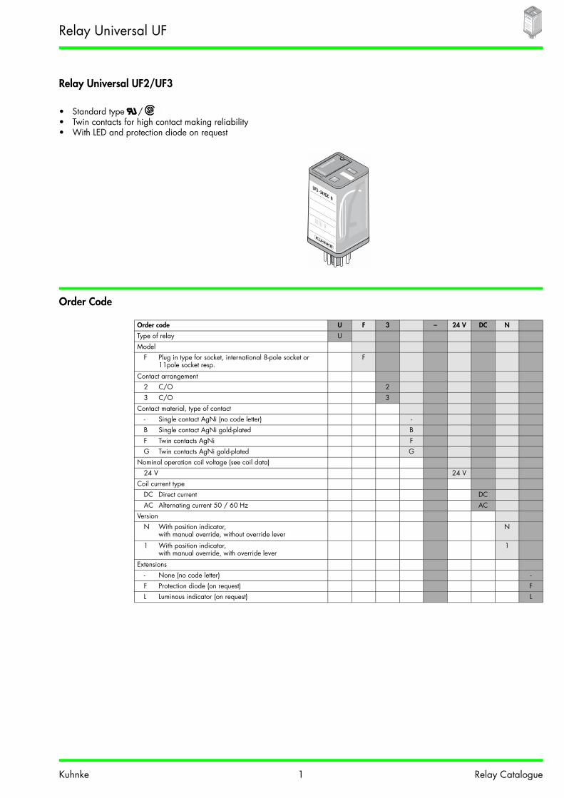
Relay Universal UF2/UF3
• Standard type /• Twin contacts for high contact making reliability • With LED and protection diode on request
Order Code
Order code U F 3 – 24 V DC N
Type of relay UModel
F Plug in type for socket, international 8-pole socket or 11pole socket resp.
F
Contact arrangement2 C/O 23 C/O 3
Contact material, type of contact- Single contact AgNi (no code letter) -B Single contact AgNi gold-plated BF Twin contacts AgNi FG Twin contacts AgNi gold-plated G
Nominal operation coil voltage (see coil data)24 V 24 V
Coil current typeDC Direct current DCAC Alternating current 50 / 60 Hz AC
VersionN With position indicator,
with manual override, without override leverN
1 With position indicator,with manual override, with override lever
1
Extensions- None (no code letter) -F Protection diode (on request) FL Luminous indicator (on request) L
Universal
UF3 - 24VDC N
Relay Universal UF
Universal
UF3 - 24VDC N

Kuhnke 2 Relay Catalogue
Contact Data Data
Dimensions, Connection Diagram(s)
Viewed on connector pins Viewed on connector pins
UF2 / UF33 UF2 UF3
General Data
UF2 / UF3
Contact arrangement 2 or 3 C/OType of contact Single contact Twin contactContact material AgNi AgNi
gold-plated AgNi AgNi
gold-plated
Nominal contact current 10 A 4 AInrush current ≤ 20 A ≤ 10 ANominal contact voltage 250 VAC / DC 250 VACMax. switching capacity (resistive) 3000 VA 1000 VAMin. switching capacity 50 mA / 20 VDC 1 mA /100 mVDC 20 mA / 10 VDC 1 mA /100 mVDC
UF2 / UF3
Pull-in-time approx.12 ms Drop-out time approx.10 ms Bounce time approx. 5 ms Mechanical service life > 20 x 106 switching cyclesTest voltage
Coil - contact 2500 VAC(C/O) - (C/O) 2500 VACContact - contact 1500 VAC
Insulation group VDE 0110b/2.79b/2.79 C250, B380Ambient temperature -25 °C to +60 °C DC
-25 °C to +40 °C AC
Vibration resistance (30 - 100 Hz) > 4 g
Weight approx. 90 gOperating range DC
Class 1(0.8 – 1.1 UN)
AC 50 HzClass 1
(0.8 – 1.1 UN)
AC 60 HzClass 2
(0.85 – 1.1 UN)
Pull-in after coil excitationwith UN at TU 20 °C 20 °C 20 °C
Drop-out > 0.05 UN > 0.15 UN > 0.15 UN
37
35.5
5972
12
14
32
34
A2A1
11 31(+) (-)
4 5
6
7
81
2
3
21
22
12
14
24
32
34
A2A1
11 31+ -
675
4 8
93
2 10
111
Relay Universal UF
Universal
UF3 - 24VDC N

Kuhnke 3 Relay Catalogue
Coil Data
Electrical Service LifeElectrical Service Life AC Switching capacity DC90 % operating Below limiting characteristic: service life of contacts
resistive load Single contacts 1 x 10⁶ switching cycles (90 % operating)inductive load Single contacts resistive load 1 contactresistive load Twin contacts 2 contacts in seriesinductive load Twin contacts 3 contacts in seriescos ϕ = 0.4 ... 0.77
Coil voltage DC
UF2 / UF3Nom. operation coil power
approx. 1.2 W Inrush current approx. 0.6 W
Coil voltageAC
UF2/UF3Nom. operation coil power approx. 2.2 / 2.0 VA
Inrush current approx. 1.5 x Nominal current
Nominal voltage(V)
Nominal resistance (Ω)
Nominal current(mA)
Nominal voltage(V)
Nominal resistance (Ω)
Nominal current50 Hz (mA)
Nominal current60 Hz (mA)
12 96 125 24 74 107 9124 384 63 60 474 43 3660 2400 25 115 1710 23 19
110 7660 14 230 7500 17 10220 30630 7.2
10 2 5 2 5 2 5000100 10005
2
5
105
106
107
2
5
2
5
Serv
ice
life
of c
onta
ct
Switching capacity in VAy in VA0 20 40 60 80 100 120 140 160 180
0.1
0.5
1
0.2
5
8
2
200 220
Switc
hing
cur
rent
in A
Switching voltage in V
Relay Universal UF
Universal
UF3 - 24VDC N

Kuhnke 4 Relay Catalogue
Universal Standard Types in Stockdard Types in Stockavailable from stock in packets of 10 pcs each
Order Specifications for Accessories UF
DC AC
UF2-12VDC1 UF3-12VDC1 UF2G-24VDC1 UF2-24VAC1 UF3-12VAC1 UF3B-230VACN
UF2-24VDC1 UF3-12VDCN UF3B-24VDC1 UF2-24VAC1L UF3-24VAC1 UF3F-24VACN
UF2-24VDC1FL UF3-24VDC1 UF3B-24VDC1FL UF2-24VACN UF3-24VAC1L UF3F-230VAC1
UF2-24VDCN UF3-24VDC1FL UF3B-24VDC1L UF2-110VAC1 UF3-24VACN UF3F-230VACN
UF2-110VDCN UF3-24VDC1L UF3B-24VDCN UF2-120VAC1 UF3-48VAC1 UF3G-110VAC1
UF3-24VDCN UF3F-24VDC1 UF2-230VAC1 UF3-110VAC1 UF3G-230VAC1
UF3-24VDCNF UF3F-24VDCN UF2-230VAC1L UF3-110VACN UF3G-230VACN
UF3-24VDCNFL UF3F-24VDCNF UF2-230VACN UF3-115VAC1L
UF3-24VDCNL UF3F-60VDCN UF3-120VAC1
UF3-48VDC1 UF3F-110VDCN UF3-230VAC1
UF3-48VDCN UF3G-24VDC1 UF3-230VAC1L
UF3-60VDCN UF3G-24VDC1FL UF3-230VACN
UF3-110VDC1 UF3G-24VDCN UF3-230VACNL
UF3-110VDC1FL UF3G-24VDCNL
UF3-110VDCN UF3G-60VDCN
UF3-125VDCN UF3G-110VDCN
UF3-220VDC1
UF3-220VDCN
UF2 UF3
Socket forScrew connectionwith quick-action fastening / retaining clip Z392 / Z434
Z395
Z345 / Z441Z393 / Z434
Z396
Screw connection with quick-action fastening and protection diode Z345.12 / Z441Screw connection with quick-action fastening and RC combination Z345.32 / Z441
Modules for socket Z396 / Z395Protection diode for 6 - 220 VDC Z396.50 Z396.50Protection / luminous diode for 24 VDC Z396.52 Z396.52RC combination for 110 / 230 VAC Z396.53 Z396.53Protection module with varistor for 24 VAC Z396.54 Z396.54Protection module with varistor for 230 VAC Z396.55 Z396.55Luminous indicator 230 VAC Z396.58 Z396.58Multi-function time module Z396.64 Z396.64
Retaining clip Z441 / Z434 Z441 / Z434
Relay Universal UF
Universal
UF3 - 24VDC N

Kuhnke 5 Relay Catalogue
Relay Universal MFlay Universal MF
• Standard type • Large contact gap, switching voltage therefore 400 VAC
Order Code
Contact Data
Order code M F 3 – 24 V DC
Type of relay MModel
F Plug in type for socket FContact arrangement
2 C/O 23 C/O 3
Contact material, type of contact- Hard silver (no code letter) -C AgCdO C
Nominal operation coil voltage (see coil data)24 V 24 V
Coil current typeDC Direct current DCAC Alternating current 50 Hz (60 Hz on request) AC
MF2 / MF3
Contact arrangement 2 or 3 C/OType of contact Single contactContact material Hard silver, AgCdONominal contact current 6 AInrush current ≤ 20 ANominal contact voltage 400 VACMax. switching capacity (resistive) 3000 VAMin. switching capacity 50 mA / 20 VDC
Relay Universal MF

Kuhnke 6 Relay Catalogue
Dimensions, Connection Diagram(s)gram(s)
Viewed on connector pins Viewed on connector pins
MF2 / MF32 / MF3 MF2 MF3
General Data
MF2 / MF3
Pull-in-time approx. 15 ms Drop-out time approx. 10 ms Bounce time approx. 10 ms Mechanical service life > 20 x 106 switching cycles DC
> 10 x 106 switching cycles AC
Test voltageCoil - contact 2500 VAC(C/O) - (C/O) 2500 VACContact - contact 1000 VAC
Insulation group VDE 0110b/2.7979 C250, B380Ambient temperature -25 °C to +70 °CVibration resistance (30 - 100 Hz) > 4 gWeight approx. 120 g Operating range DC
Class 1(0.8 – 1.1 UN)
AC 50 HzClass 1
(0.8 – 1.1 UN)
Pull-in after coil excitationwith UN at TU 20 °C 20 °C
Drop-out > 0.05 UN > 0.15 UN
37.5
37
68.5
81.5 12
14
32
34
A2A1
11 31
+ -
4 5
6
7
81
2
3
21
22
12
14
24
32
34
A2A1
11 31+ -
675
4 8
93
2 10
111
Relay Universal MF

Kuhnke 7 Relay Catalogue
Coil Data
Electrical Service LifeElectrical Service Life AC Switching capacity DC90 % operating Below limiting characteristic: service life of contacts
resistive load 1 x 10⁶ switching cycles (90 % operating)inductive load resistive load
cos ϕ = 0.4 ... 0.74 ... 0.7
Coilvoltage
DC
MF2 / MF3Nom. operation coil power
appr. 1.5 W Pull-in power appr. 0.7 W
Coilvoltage
AC, 50 Hz
MF2Nom. operation coil power
appr. 1.8 VA Inrush current appr. 1.7 x nom. current
MF3Nom. operation coil power
appr. 3.8 VA Inrush current appr. 1.7 x nom. current
Nominal voltage (V)
Nominal resistance(Ω)
Nominal current (mA)
Nominal voltage (V)
Nominal resistance (Ω)
Nominal current (mA)
Nominal resistance (Ω)
Nominal current(mA)
12 103 120 12 17.9 170 9.25 34024 442 54 24 85.2 71 45.2 14040 1030 39 42 268 40 127 9360 2410 25 60 547 28 268 62
110 7710 14 110 1910 16 1030 31220 29400 7.5 230 7710 8 3890 17
10 2 5 2 5 2 5000100 10005
2
5
105
106
107
2
5
Serv
ice
life
of c
onta
ct
Switching capacity in VA0 20 40 60 80 100 120 140 160 180 200 220
0.1
0.15
0.2
0.30.4
0.60.8
1
1.5
2
3
4
6
Switc
hing
cur
rent
in A
Switching voltage in V
Relay Universal MF

Kuhnke 8 Relay Catalogue
Relay Universal MF2 for Current Monitoringy Universal MF2 for Current Monitoring
• Standard type • Large contact gap,
switching voltage therefore 400 VAC• Monitoring of DC and AC currents
Order Codeder Code
Order Specifications
for current relay MF2 for the monitoring of DC filament bulbs and other DC loadsmonitoring of DC filament bulbs and other DC loads
for current relay MF2 for the monitoring of AC filament bulbs and other AC loads
Order code M F 2 – 0 40
Type of relay MModeldel
F Plug-in type with socket FContact arrangement
2 C/O 2Coil current type
0 Direct current 01 Alternating current 50 Hz (60 Hz on request) 1
Coil number (see order specs)40 40
UP 6 VDC 12 VDC 24 VDC 60 VDC 110 VDC 115 VDC 220 VDC
10 W MF2-052 MF2-046 MF2-040 - - - -
25 W MF2-056 MF2-052 MF2-046 MF2-040 MF2-034 MF2-030 -
40 W - MF2-056 MF2-052 MF2-040 MF2-034 MF2-037 MF2-030
60 W - - MF2-052 MF2-046 MF2-040 MF2-040 MF2-034
65 W - - MF2-052 MF2-046 MF2-040 MF2-040 MF2-034
80 W - - MF2-056 MF2-046 MF2-046 MF2-044 MF2-037
100 W - - MF2-056 MF2-052 MF2-046 MF2-046 MF2-040
150 W - - - MF2-052 MF2-046 MF2-046 MF2-040
200 W - - - MF2-056 MF2-052 MF2-052 MF2-046
UP
6 VAC50 Hz
12 VAC50 Hz
24 VAC50 Hz
60 VAC50 Hz
110 VAC50 Hz
115 VAC50 Hz
230 VAC50 Hz
10 W MF2-151 MF2-146 MF2-143 - - - -
25 W - MF2-157 MF2-151 MF2-143 MF2-137 MF2-137 MF2-130
40 W - MF2-157 MF2-151 MF2-144 MF2-137 MF2-137 MF2-134
60 W - - MF2-157 MF2-151 MF2-144 MF2-144 MF2-137
65 W - - MF2-157 MF2-151 MF2-144 MF2-144 MF2-137
80 W - - MF2-157 MF2-151 MF2-144 MF2-144 MF2-137
100 W - - - MF2-151 MF2-146 MF2-146 MF2-143
150 W - - - MF2-157 MF2-151 MF2-151 MF2-144
200 W - - - MF2-157 MF2-152 MF2-151 MF2-146
Relay Universal MF for Current Monitoringfor Current Monitoring

Kuhnke 9 Relay Catalogue
Contact Data
Dimensions, Connection Diagram(s)See relay universal MF
ApplicationExample: Navigation lightsUse as monitoring relayin accordance with connection diagram
General Datal Data
Order Specifications for Accessories MF
MF2 for current monitoringfor current monitoring
Contact arrangement 2 C/OType of contact Single contactContact material Hard silverNominal contact current 6 AInrush current ≤ 20 ANominal contact voltage 400 VACMax. switching capacity (resistive) 3000 VAMin. switching capacity 50 mA / 20 VDC
MF2 for current monitoring
Pull-in-time approx. 15 msDrop-out time approx. 10 ms Bounce time approx. 10 ms Mechanical service life > 20 x 106 switching cycles DC
> 10 x 106 switching cycles AC
Test voltageCoil - contact 2500 VAC(C/O) - (C/O) 2500 VACContact - contact 1000 VAC
Insulation group VDE 0110b/2.79 C250, B380Ambient temperature -25 °C to +40 °C Vibration resistance (30 - 100 Hz) > 4 g Weight approx. 120 g Operating range 0.9 – 1.1 INResidual direct current ripple < 25 %
MF2 MF3
Socket forScrew connection with quick-action fastening /retaining clip Z392 / Z434
Z395
Z345 / Z434Z393 / Z434
Z396
Navigation light Control light
Relay Universal MF for Current Monitoringay Universal MF for Current Monitoringor Current Monitoring

Kuhnke 10 Relay Catalogue
Time Relay Universal 130
• Time relay for relay universal series• 2 C/O
Order Code
Contact DataData
Order code 130 – 2 – 01 – 2 – 3 – 24 VDC/AC
Type of relay 130Contact arrangement
2 C/O 2Function
01 Pull-in delay 0102 Switch-off delay 0203 Blinker 0306 Switch-on wiper 06
Connection diagram2 11pole 2
Nominal time range / Impulse frequency
3 0.1 - 3 s approx. 330 0.5 - 30 s approx. 30180 2.0 - 180 s approx. 180600 4.0 - 600 s (on request) 600
for function 0350 5 - 50 pulses/min approx. 50200 40 - 200 pules/min approx. 200
Nominal voltage24 VDC/AC 24 VDC/AC110 VAC 110 VAC230 VAC 230 VAC
130
Contact arrangement 2 C/OType of contact Single contactContact material AgCdONominal contact current 8 AInrush current ≤ 15 ANominal contact voltage 250 VACMax. switching capacity 2000 VAMin. switching capacity 100 mA / 5 VDC
10
0
130-2-01-2-30
24V DC/AC
Time Relay Universal 1303010
0
130-2-01-2-30
24V DC/AC

Kuhnke 11 Relay Catalogue
Dimensions, Connection Diagram(s)
Pull-in delay 01 Switch-off delay 02
Blinker 03 Switch-on wiper 06
General Data
Control Circuit
Order Specifications for Accessoriesfications for Accessories
130
Mechanical service life > 5 x 10⁶ switching cyclesElectrical service life > 1 x 10⁵ switching cyclesTest voltage
Inputs - contact 2500 VACInsulation group VDE 0110b/2.7979 C250Ambient temperature 0 °C to +40 °CWeight approx. 60 g Operating range DC / AC
Class 1 0.8 - 1.1 UN
Pull-inafter coil excitation with UN at TU 20 °C
Nominal frequency 40 - 60 HzRated power 0.8 W
Relay 130 ... 01, 130 ... 03, 130 ... 06 130 ... 02
Contact voltage Supply voltage ≤ 15 VVContact current ≤ 150 mA ≤ 15 mAContact load approx. 1 VA ≤ 0.2 WInput impedance approx. 180 Ω 1 kΩPulse duration ≤ 70 ms
Relay 130
Socket for Screw connection with quick-action fastening
Z345Z393
2 10 3 1 4 9 11 8 5 6 7
A1 A2 14 11 12 34 31 32 22 21 24
Uv
2 10 3 1 4 9 11 8 5 6 7
A1 A2 14 11 12 34 31 32 22 21 24
Uv Start
10 0 50
35.5
59.5
73
2 10 3 1 4 9 11 8 5 6 7
A1 A2 14 11 12 34 31 32 22 21 24
Uv
2 10 3 1 4 9 11 8 5 6 7
A1 A2 14 11 12 34 31 32 22 21 24
Uv
Start
Time Relay Universal 130versal 13010
0
130-2-01-2-30
24V DC/AC

Kuhnke 12 Relay Catalogue
Function
Pull-in delay 01Switching with supply voltage
Switch-off delay 022Switching with start contact
Blinker 03Switching with supply voltage
Switch-on wiper 06Switching with start contact
Switching with supply voltage
t>tw
tv
onoff
Supply voltage
Relay contact/LED onoff
t>tw
t>tvtv tv
Supply voltage
Relay contact/LED
Start contact
onoff
onoff
onoff
t>tw
tv tv
Supply voltage
Relay contact/LED
onoff
onoff
Supply voltage
Relay contact/LED
Start contactt>twt>tw
t<tvtvtw
onoff
onoff
onoff
Supply voltage
Relay contact/LED
Start contact
t>twt>tw
t<tvtvtw
onoff
onoff
onoff
Time Relay Universal 130y Universal 13010
0
130-2-01-2-30
24V DC/AC

Kuhnke 13 Relay Catalogue
Socket Z392
Socket Z393
Socket Z392
Socket design logical, additional modules not supportedTerminal capacity
solid conductor 2 x 2.5 mm2
flexible conductor with ferrule 2 x 2.5 mm2
Terminal designation in accordance with EN50005 and IEC67Mounting Rail EN50022-35 x 7.5/15
Screw mounting 2 x M3 or central M4
Screw terminals Head screws metric M3Torque in accordance with DIN EN 60999 0.5 NmNominal current 10 AInsulation group VDE 0110b/2.79 C250, B380Electrical shock protection in accordance with VBG4 (professional association), VDE 0106 part 100), VDE 0106 part 100Weight 63 gRetaining clip Z434
Socket Z393
Socket design additional modules not supportedTerminal capacity
solid conductor 2 x 2.5 mm2
flexible conductor with ferrule 2 x 2.5 mm2
Terminal designation in accordance with EN50005 and IEC67Mounting Rail EN50022-35 x 7.5/15
Screw mounting 2 x M3 or central M4
Screw terminals Head screws metric M3Torque in accordance with DIN EN 60999 0.5 NmNominal current 10 AAInsulation group VDE 0110b/2.79 C250, B380Electrical shock protection in accordance with VBG4 (professional association), VDE 0106 part 100Weight 63 gRetaining clip Z434
D11
6
3
21
8
11
1 2
7
A1
A2
5
22
4
12
24
14
Z392 10A 380VAC
2738
65
24
A2 A11121
22 12 14
8
4
3E2
9
2
10
111
14
34
A1
A2
11
31
7
5
6
21
32
12
24
22Z393 10A 380VAC
2738
65
32
34
A2 31 11 A1
14
24 21 22 12
Accessories for Relay Universal niversal

Kuhnke 14 Relay Catalogue
Socket Z345
Z345 Z345.12 Z345.32Protection diode up to 220 VDC RC-protection unit 110 / 230 VAC
Socket Z345
Socket design logical, additional modules not supportedTerminal capacity
solid conductor 2 x 2.5 mmx 2.5 mm2
flexible conductor with ferrule 2 x 2.5 mm2
Terminal designation in accordance with EN50005 and IEC67Mounting Rail EN50022-35 x 7.5/15
Screw mounting 2 x M3 or central M4
Screw terminals Head screws metric M2.6Torque in accordance with DIN EN 60999 0.5 NmNominal current 10 AInsulation group VDE 0110b/2.79 C250, B380Electrical shock protection in accordance with VBG4 (professional association), VDE 0106 part 100Weight 50 gRetaining clip Z441
UniversalZ345.12
34 329
8 225 12
4
247
143
A2
21 11A1
31
10
11
6 1
2
24.536.5
78
A2 3121
2422
11 A1
1412
3432
A2 3121
2422
11– +
A1
1412
3432
A2 3121
2422
11 A1
1412
3432
Accessories for Relay UniversalUniversal

Kuhnke 15 Relay Catalogue
Socket Z395
Socket Z396
Socket Z395
Socket design logical, additional modules supportedTerminal capacity
solid conductor 2 x 2.5 mm2
flexible conductor with ferrule 2 x 1.5 mm2
Terminal designation in accordance with EN50005 and IEC67Mounting Rail EN50022-35 x 7.5/15
Screw mounting 2 x M3 or central M4
Screw terminals Head screws metric M3Torque in accordance with DIN EN 60999 0.5 NmNominal current 10 AInsulation group VDE 0110b/2.79 C250, B380B380Electrical shock protection in accordance with VBG4 (professional association), VDE 0106 part 100Weight 68 g
Socket Z396
Socket design logical, additional modules supportedTerminal capacity
solid conductor 2 x 2.5 mm2
flexible conductor with ferrule 2 x 1.5 mm2
Terminal designation in accordance with EN50005 and IEC67Mounting Rail EN50022-35 x 7.5/15
Screw mounting 2 x M3 or central M4
Screw terminals Head screws metric M3Torque in accordance with DIN EN 60999 0.5 NmNominal current 10 AInsulation group VDE 0110b/2.79 C250, B380Electrical shock protection in accordance with VBG4 (professional association), VDE 0106 part 100Weight 68 g
10A 400VAC
12A 300VAC
LR 26716
10A 300VAC
E 113714
Universalz 395
246 22
5
77
81
2
124 14
A2A2
2111
A1
3
MADE IN
ITALY
26 38
75
24
A2A2 A11121
22 12 14
6
77 218
5 4 3
2422
32
34
1412
3121
A2
A2
11A1
11
6
10
10
1
2
7
5
E5
8
9
3
4
UniversalZ396
26 38
75
34 32 24 22 14 12
A2 A2 31 21 11 A1
Accessories for Relay Universal y Universal

Kuhnke 16 Relay Catalogue
Modules for Socket Z395/Z396/Z396
Z396.50 Z396.52 Z396.53Protection diode Protection / luminous diode RC-protection unit
for 24 VDC for 110 - 240 VAC
Z396.54 Z396.55 Z396.58 Varistor for 24 VAC Varistor for 230 VAC Luminous diode for 230 VAC
Universal Timer Module Z396.64 for Socket Z3964 for Socket Z396
• Timer module for relay universal series• Multi voltage of 24 - 240 VDC/AC/AC• Multi-functional with 8 functions• Multi time range from 50 ms - 240 h
Technical data see pages 17 - 18.
Z396.506/220 V DC
-A2
A2+
34 10
36A1 +- A2 A1+- A2 A1 A2
A1A2
U
A1A2
U
A1 A2
B1
10 35
47
A2
–(~)
A131 21B1 11
+(~)Start
Accessories for Relay Universal Relay Universal

Kuhnke 17 Relay Catalogue
Contact Data
When using relay UF3 and socket Z396
General Data
Time Rangesme Ranges
Contact arrangement 3 change-over contacts (C/O)Type of contact Single contact Twin contactContact material AgNi AgNi
gold-plated AgNi AgNi
gold-plated
Nominal contact current 10 A 4 AInrush current ≤ 20 A ≤ 10 ANominal contact voltage 250 VAC 250 VACMax. switching capacity (resistive) 3000 VA 1000 VAMin.switching capacity 50 mA / 20 VDC 1 mA /100 mVDC 20 mA / 10 VDC 1 mA /100 mVDC
Voltage range supply 24 V to 240 VAC, 24 V to 250 VDC -15 % to +10 % in relation to U+10 % in relation to UN
Voltage range control contact at 24 V min. 80 % of supply voltageat 230 V min. 95 % of supply voltage
Duty cycle 100 %Frequency 48 Hz to 63 HzPower failure bridging time max.10 msRecovery time max.100 ms at 25 °C, max.150 ms at 55 °CAdjustments Time ranges and functions selectable via DIP switch
Time setting via potentiometer
Temperature range -25 °C to +55 °CIndicators Green "Power on" LED
Green LED flashes during delay time
Supply voltage terminal plug-in to socket Z396Control voltage terminal Terminal B1
Time ranges, time range limit Adjustment range
1 s 0.05 - 1 s
10 s 0.5 - 10 s
1 min 3 s - 60 s
10 min 30 s - 600 s
1 h 3 min - 60 min
10 h 30 min - 600 min
1 day/24 h 1.2 h - 24 h
10 day/240 h 12 h - 240 h
Accessories for Relay Universal ories for Relay Universal

Kuhnke 18 Relay Catalogue
Time Functions
Function Description of function Function diagram
E Switch-on delay Start by switching the supply voltage
R Switch-off delayStart with control contact
Ws Switch-on wiperStart with control contact
Wa Switch-off wiperStart with control contact
Wu Switch-on wiperStart by switching the supply voltage
Es Switch-on delayStart with control contact
Bp Blinker 0 - startingStart by switching the supply voltage
Bi Blinker 1 - startingStart by switching the supply voltage
U
Rt
S
U
Rt
S
U
Rt
S
U
Rt
U
Rt
S
U
Rt
U
Rtt
U
Rtt
Accessories for Relay Universal niversal

Kuhnke 19 Relay Catalogue
Quattro Relay 114A4
• Standard type / • With LED and protection diode on request
Order Code
Contact Data
Order Code Quattro Relay 114 A 4 – 24 V DC N
Type of relay Quattro Relay 114Model
A Plug-in type AContact arrangement
2 C/O (on request) 24 C/O 4
Contact material- AgNi (no code letter) -B AgNi gold-plated B
Nominal operation coil voltage (see coil data)24 V 24 V
Coil current typeDC Direct current DCAC Alternating current (50 / 60 Hz) AC
VersionsN with position indicator N
with manual overridewithout override lever
1 with position indicator 1with manual overridewith override lever
114 A4
Contact arrangement 4 C/OType of contact Single contactContact material AgNi AgNi gold-platedNominal contact current 10 AInrush current ≤ 20 ANominal contact voltage 110 VDC / 250 VACMax. switching capacity (resistive) 144 W / 2000 VAMin. switching capacity 10 mA / 5 V 1 mA / 100 mV
Quattro-Relais
Quattro Relay 114
Quattro-Relais

Kuhnke 20 Relay Catalogue
Dimensions, Connection Diagram(s)
Viewed on terminals Viewed on terminals
114 A4 114 A2 (on request)
General Data
Relay with protection diode
Standard114 ... F1
+ to A1 (13)- to A2 (14)
Special114 ... F
- to A1 (13)+ to A2 (14)
114 A4
Pull-in-time approx. 10 msDrop-out time approx. 10 msBounce time approx. 5 msMechanical service life > 20 x 106 switching cycles Test voltage
Coil - contact 2500 VAC(C/O) - (C/O) 2000 VACContact - contact 1000 VAC
Insulation group VDE 0110b/2.79 B250Insulation coordination to DIN EN 61810-5/ VDE 0435 Part 140
Operating voltage 250 V
Overvoltage category III
Pollution degree 3
Ambient temperature -40 °C to +60 °C
Vibration resistance (30 - 100 Hz) > 2 g N/C> 10 g N/O
Weight approx. 33 gOperating range DC
Class 1(0.8 - 1.1 UN)
ACClass 2
(0.85 - 1.1 UN)
Pull-in after coil excitationwith UN, nominal current at TU 60 °C 20 °C
Drop-out > 0.05 UN > 0.15 UN
637
.4
27.5
210.52
(13)
(14)
(9)
(12)
A1
A2
11
41 44 42
14 12
(8)
(5)
(4)
(1)
(10)21 24 22
(6) (2)
(11)31 34 32
(7) (3)
(13)
(14)
(9)
(12)
A1
A2
11
41 44 42
14 12
(8)
(5)
(4)
(1)
Quattro Relay 114
Quattro-Relais

Kuhnke 21 Relay Catalogue
Coil Data
Electrical Service LifeElectrical Service Life AC Switching Capability DC90 % operating Below limiting characteristic: service life of contacts
resistive load 2 x 10⁴ switching cycles (90 % operating)conductive load resistive loadcos ϕ = 0.4 ... 0.7
Quattro Relay Standard Types in Stockavailable from stock in packs of 10 pcs each
Coil voltage DC
114A4Pull-in power approx. 0.42 W
Nom. operation power approx. 1 W
Coil voltageAC
114A4Nom. operation power appr. 1.2/0.98 VA
Inrush current appr. 1.5 x nominal current
Nominal voltage(V)
Nominal resistance (Ω)
Nominal current (mA)
Nominal voltage(V)
Nominal resistance (Ω)
Nominal current50 Hz (mA)
Nominal current 60 Hz (mA)
12 143 84 12 46.5 100 8124 576 42 24 177 50 4148 2250 21 48 762 25 20
110 12100 9 115 4570 10 8.5120 4570 11 8.8230 19040 5.2 4.2
DC AC
114 A4-12VDC1 114 A4B-24VDC1 114 A4-12VAC1 114 A4B-230VAC1
114 A4-12VDC1L 114 A4B-24VDCN 114 A4-24VAC1 114 A4B-230VACN
114 A4-12VDCN 114 A4-24VAC1L
114 A4-24VDC1 114 A4-24VACN
114 A4-24VDC1F1 114 A4-48VAC1
114 A4-24VDC1FL 114 A4-115VAC1
114 A4-24VDC1FL1 114 A4-115VAC1L
114 A4-24VDC1L 114 A4-115VACN
114 A4-24VDCN 114 A4-120VAC1
114 A4-24VDCNF 114 A4-120VAC1L
114 A4-24VDCNFL 114 A4-230VAC1
114 A4-24VDCNFL1 114 A4-230VAC1L
114 A4-48VDC1 114 A4-230VACN
114 A4-48VDC1L 114 A4-230VACNL
114 A4-48VDCN
114 A4-110VDC1
114 A4-110VDCN
2 5 2 5 2 5000100 1000100.05
0.2
0.5
0.1
1
10
2
5
Serv
ice
life
of c
onta
ct
Switching capacity in VA20 40 60 80 100 120 140 160 220180 2000
0.1
0.5
1
0.2
5
10
20
2
Switc
hing
cur
rent
in A
Switching voltage in V
Quattro Relay 114
Quattro-Relais

Kuhnke 22 Relay Catalogue
Order Specifications for Accessories
Socket Z366.02
Relay 114 A4/A2
Socket for screw connection with quick-action fastening, C250 Z366.02
Socket for screw connection with quick-action fastening, C250, safe separation Z368.02
Socket for screw connection with quick-action fastening incl. retaining spring Z376.42
Modules for socketsProtection diode + at A2 Z318.50Protection / luminous diode 24 VDC + at A2 Z318.57Protection / luminous diode 24 VDC + at A1 Z318.51Protection diode + at A1 Z318.53Protection module with varistor 24 VAC Z318.54Protection module with varistor 230 VAC Z318.55Luminous diode for 24 VAC/DC Z318.52Luminous diode for 230 VAC Z318.58
Retaining clip Z366.80Socket for printed circuit Z378Socket for soldered connection Z374
Socket Z366.02
Socket design logical
Terminal capacity
solid conductor 2 x 1.5 mm2
flexible conductor with ferrule2 x 1.0 mm2
Terminal designation in accordance with DIN 46199 and IEC 67Mounting Rail EN50022-35 x 7.5/15
Screw mounting 2 x M3
Screw terminals Head screws metric M3Torque in accordance with DIN EN 60999 0.5 NmNominal current 10 AInsulation group VDE 0110b/2.79 C250Electrical shock protection in accordance with VBG4 (professional association), VDE 0106 part 100Weight 52 gRetaining clip Z366.80
3
Z366.02
MADE IN ITALY
12A 300VAC
LR 26716
10A 300VAC
COIL
COIL
A2
14
4131
2111
22
42
32NC
4
2
1
514
12
1211
COM10
9
13
A1
26.975.2
Z366.80
42.5
79.5
44
42
A2 A1
41 31 21 11
34
32
24
22
14
12
Accessories for Quattro Relay 114

Kuhnke 23 Relay Catalogue
Socket Z368.02
Socket Z376.42
Socket Z368.02
Socket design logical, safe separation
Terminal capacity
solid conductor 2 x 2.5 mm2
flexible conductor with ferrule 2 x 1.5 mm2
Terminal designation in accordance with EN50005 and IEC 67Mounting Rail EN50022-35 x 7.5/15
Screw mounting 2 x M3
Screw terminals Head screws metric M3Torque in accordance with DIN EN 60999 0.5 NmNominal current 12 AInsulation group VDE 0110b/2.79 C250Electrical shock protection in accordance with VBG4 (professional association), VDE 0106 part 100Weight 70 gRetaining clip Z366.80
Socket Z376.42
Socket design logical, with retaining spring
Terminal capacity
solid conductor 2 x 1.5 mm2
flexible conductor with ferrule 2 x 1.5 mm2
Terminal designation in accordance with EN50005 and IEC 67Mounting Rail EN50022-35 x 7.5/15
Screw mounting 2 x M4
Screw terminals Head screws metric M3Torque in accordance with DIN EN 60999 0.5 NmNominal current 12 AInsulation group VDE 0110b/2.79 B250Electrical shock protection in accordance with VBG4 (professional association), VDE 0106 part 100Weight 49 gRetaining clip Z366.80Retaining spring enclosed
Z368.02
MADE IN ITALY12A 300VAC
75 27
61 44
42
A2 A2 A1
34
32
24
22
14
41 31 21 11
12
Z376.42
10A 300VAC
66.5
26 29
29.5
44
42
A2 A1
41 31 21 11
34
32
24
22
14
12
Accessories for Quattro Relay 114

Kuhnke 24 Relay Catalogue
Modules for Sockets Z366.02, Z368.02, and Z376.42
Z318.50 Z318.51 Z318.52Protection diode + to A2 Protection / luminous diode for 6 - 24 VDC + to A1 LED for 6 - 24 VAC/DC
Z318.53 Z318.54 Z318.55 Protection diode + to A1 Varistor for 24 VAC Varistor for 230 VAC
Z318.57 Z318.58 Protection / luminous diode for 6 - 24 VDC + to A2 LED for 110/230 VAC
A1+
-A2
Z318.516/24 V DC
8 12
23A1 -+ A2
A1 +- A2 A1 +- A2 ~ ~
A1 +- A2 A1A2
U
A1A2
U
A1 -+ A2 A1A2
Accessories for Quattro Relay 114

Kuhnke 25 Relay Catalogue
Miniature Relay 111A2/H1
• Standard type /• With LED and protection diode on request
(please note polarity)
Order Codeode
Contact Data
Order code 111 A 2 – 24 V DC
Type of relay 111Model
A Plug-in type AH Plug-in type H
Contact arrangement1 C/O (model H) 12 C/O (model A) 2
Nominal operation coil voltage (see coil data)24 V 24 V
Coil current typeDC Direct current DCAC Alternating current (50 / 60 Hz) AC
111H1 111A2
Contact arrangement 1 C/O 2 C/OType of contact Single contactContact material AgCdO Silver gold-plated Nominal contact current 10 A 3 AInrush current ≤ 10 A ≤ 5 ANominal contact voltage 250 VAC / DC 250 VAC / DCMax. switching capacity (resistive) 1540 VA 660 VAMin. switching capacity 50 mA / 20 VDC 20 mA / 5 VDC
111 A2
111A2-24VDC
111 H1
111H1-24VDC
Miniature Relay 111111A2-24VDC

Kuhnke 26 Relay Catalogue
Dimensions, Connection Diagram(s)
111 A2 111 H1
Viewed on terminals Viewed on terminals
General Data
Coil Data
111H1 111A2
Pull-in-time approx. 10 ms Drop-out time approx. 8 ms Bounce time approx. 3 ms Mechanical service life > 20 x 106 switching cyclesTest voltage
Coil - contact 2000 VAC 1500 VAC(C/O) - (C/O) 1500 VACContact - contact 1000 VAC
Insulation group VDE 0110b/2.7979 C30, B125, A250Ambient temperature -25 °C to +50 °CVibration resistance (30 - 100 Hz) > 10 gWeight approx. 20 g Operating range Class 2 (0.85 - 1.1 UN)Pull-in
after coil excitationwith UN at TU 20 °C
Drop-out > 0.05 x UN DC> 0.15 x UN AC
Coil voltage DC
111A2/H1Pull-in power approx. 0.5 W
Nom. operation power approx. 0.8 W
Coil voltageAC
111A2/H1Nom. operation power appr. 0.9/1 VA Inrush current approx. 1.5 x nominal
current
Nominal voltage(V)
Nominal resistance (Ω)
Nominal current(mA)
Nominal voltage(V)
Nominal resistance (Ω)
Nominal current50 Hz (mA)
Nominal current60 Hz (mA)
12 188 64 12 76.5 86 7524 750 32 24 300 42 3748 2660 18 48 1280 20 18
115 7210 8.9 7.8
14
27.5
35.6
5.5 1.2
2.6
3
14
27.5
35.6
5.5 1.2
2.6
3
2.64.8 Contact
Coil
+
–13
14
9 5 1
12 8 4+
–13
14
9 5 1
Miniature Relay 111111A2-24VDC

Kuhnke 27 Relay Catalogue
Electrical Service LifeElectrical Service Life AC90 % operatingg
resistive loadinductive loadcos ϕ = 0.4 ... 0.7
111 H1 111 A2
Switching Capability DCBelow limiting characteristic: service life of contacts1 x 106 switching cycles (90 % operating)resistive load
111 H1 111 A2
Order Specifications for Accessories 111 A2/H1
Relay 111 H1 111 A2
Socket forscrew connection with quick-action fastening Z375.12 Z375.02
printed circuit Z377.10 Z377solder connection Z373.10 Z373
Retaining clip Z475 Z475
10 2 5 2 5 2 5000100 10005
2
5
105
106
107
2
5
Serv
ice
life
of c
onta
ct
Switching capacity in VA10 2 5 2 5 2 5000100 1000
5
2
5
105
106
107
2
5
Serv
ice
life
of c
onta
ct
Switching capacity in VA
0 20 40 60 80 100 120 140 160 180 200 2200.1
0.5
1
0.2
5
10
2
Switching voltage in V
Switc
hing
cur
rent
in A
0 20 40 60 80 100 120 140 160 180 200 2200.1
0.5
1
0.2
5
8
2
Switching voltage in V
Switc
hing
cur
rent
in A
Miniature Relay 111111A2-24VDC

Kuhnke 28 Relay Catalogue
Socket Z375.12Z375.12
Socket Z375.02
Socket Z375.12
Socket design logicalTerminal capacity
solid conductor 2 x 1.5 mm2
flexible conductor with ferrule 2 x 1.0 mm2
Terminal designation in accordance with EN50005 and IEC 67Mounting Rail EN50022-35 x 7.5/15
Screw mounting 2 x M4
Screw terminals Head screws metric M3Torque in accordance with DIN EN 60999 0.5 NmNominal current 10 AInsulation group VDE 0110b/2.79 C380Electrical shock protection in accordance with VBG4 (professional association), VDE 0106 part 100BG4 (professional association), VDE 0106 part 100Weight 27 gRetaining clip Z475
Socket Z375.02
Socket design logicalTerminal capacity
solid conductor 2 x 1.5 mm2
flexible conductor with ferrule 2 x 1.0 mm2
Terminal designation in accordance with DIN 46199 and IEC 67Mounting Rail EN50022-35 x 7.5/15/15
Screw mounting 2 x M4
Screw terminals Head screws metric M3Torque in accordance with DIN EN 60999 0.5 NmNominal current 3 AInsulation group VDE 0110b/2.79 C250Electrical shock protection in accordance with VBG4 (professional association), VDE 0106 part 100Weight 27 gRetaining clip Z475
Z375.12
20 64
30
–+14 13
Z37
5.0
2
20 64
30
–+14 13
Accessories for Relay 111ccessories for Relay 111

Kuhnke 29 Relay Catalogue
Socket Z377.10
Socket Z377
Socket Z377.10
Terminal Soldered pinsMounting Soldered to circuit boardInsulation group VDE 0110b/2.79 B30, A125Weight approx. 6 g Retaining clip Z475
Socket Z377
Terminal Soldered pinsMounting Soldered to circuit board
Insulation group VDE 0110b/2.79 B30, A125Weight approx. 6 g Retaining clip Z475
31
12.5
181511
3
25.5m
in. 1
84.
4
*min. 31 11.854.7 5.85
31
12.5
181511
3
1.5x0.5 25.5
*min. 31 16.810.4
4.1 9
min
.13
.6
Accessories for Relay 111
* min. 36 when using retaining clips
* min. 36 when using retaining clips
Coil 1.6 mmContacts 2.1 mm
Hole diameter
Hole diameter 1.6 mm

Kuhnke 30 Relay Catalogue
Industrial Switching Relay I
• Standard type / , specify in order• Twin contacts for high contact making reliability • 2, 4, 6 or 8 C/O possible• Large contact gap, switching voltage therefore 400 V00 V• Supplied with blow-out magnet for high DC loads
Order Code
Order code I A 4 – 24 V DC
Type of relay IModel
A Plug-in type for socket or soldered connection A
C For 2.8 mm connector, B-extension required for EN-mounting
C
G For printed circuit G
Contact arrangement2 C/O 24 C/O 46 C/O (for DC only) 68 C/O (for DC only) 8
Contact material, type of contact- Hard silver (no code letter) -C AgCdO CF Twin contacts hard silver FG Twin contacts hard silver gold-plated G
Nominal operation coil voltage (see coil data)24 V 24 V
Coil current typeDC Direct current DCAC Alternating current 50 Hz (60 Hz on request)
for IA2 and IA4 onlyAC
Extensions- None (no code letter) -M Blow-out magnet M
B Quick-action fastening for railEN50022-35 x 7.5(combination M/B not for IA2/C2)
B
1 A4
24V P
Made in Germany
25
Industrial Switching Relay IRelay I1 A4
24V P
Made in Germany
25

Kuhnke 31 Relay Catalogue
Contact Data
Dimensions, Connection Diagram(s)
I I ... M IG
I
Contact arrangement 2, 4, 6, 8 C/O
Type of contact Single contact Twin contactContact material hard silver AgCdO hard silver hard silver gold-plated
Nominal contact current 6 A 4 AInrush current ≤ 20 A ≤ 10 ANominal contact voltage 400 VAC, 250 V (with 8 C/O)Max. switching capacity (resistive) 3000 VA, 2000 VA (with 8 C/O) 1200 VAMin. switching capacity 50 mA / 20 VDC 50 mA / 20 VDC 20 mA / 10 VDC 1 mA / 100 mV
31.5
5562
.5
5162
2468
7384
8 C/O
A1 A2
21
22
24
11
12+
-
(+)
-
(+)
(-)
+
-
(+)
(-)
+
(-)
+
-
(+)
(-)14
31
32
34
41
42
44
61
62
64
51
52+
-
(+)
-
(+)
(-)
+
-
(+)
(-)
+(-)
+
-
(+)
(-)54
71
72
74
81
82
84
A1 A2
21
22
24
11
12
14
31
32
34
41
42
44
61
62
64
51
52
-
54
71
72
74
81
82
84
2.5
152.5
Industrial Switching Relay I1 A4
24V P
Made in Germany
25
8
6 (C/O)
4 (C/O)
2 (C/O)
(C/O)

Kuhnke 32 Relay Catalogue
General Data
Coil Data
I
Pull-in-time approx. 15 ms Drop-out time approx. 10 ms Bounce time approx. 6 ms Mechanical service life > 20 x 106 switching cycles DC
> 15 x 106 switching cycles ACTest voltage
Coil - contact 2500 VAC(C/O) - (C/O) 2500 VACContact - contact 1000 VAC
Insulation group VDE 0110b/2.799 C250, B380Ambient temperature -25 °C to +60 °C DC
-25 °C to +40 °C AC
Vibration resistance (30 - 100 Hz) > 2 gWeight approx. 140 g to 180 g Operating range DC
Class 1 (0.8 - 1.1 UN)
AC, 50 HzClass 1
(0.8 - 1.1 UN)
Pull-in after coil excitationwith UN at TU 20 °C
Drop-out > 0.05 UN > 0.15 UN
Coil voltageDC*
*Other voltages on request
IA2Nom. operation coil power appr. 0.9 W
Pull-in power appr. 0.5 W
Coil voltageAC, 50 Hz*
IA2Nom. operation coil power appr. 3.5 VA
Inrush current appr.1.7 x nominal current
Nominal voltage (V) Nom. resistance (Ω) Nominal current (mA) Nominal voltage (V) Nom. resistance (Ω) Nominal current (mA)
12 208 58 12 7.7 25024 702 34 24 37 10040 1980 20 42 106 6760 4030 15 60 208 50
110 12800 8.6 110 853 22220 48700 4.5 230 3120 13
Coil voltageDC*
*Other voltages on request
IA4Nom. operation coil power appr. 1.7 W
Pull-in power appr. 0.8 W
Coil voltageAC, 50 Hz*
IA4Nom. operation coil power appr. 5 VA
Inrush current appr. 1.7 x nominal current
Nominal voltage (V) Nom. resistance (Ω) Nominal current (mA) Nominal voltage (V) Nom. resistance (Ω) Nominal current (mA)
12 88 140 12 5 42024 363 66 24 22 21040 853 47 42 71 11060 1980 30 60 139 80
110 8010 14 110 458 46220 30500 7.2 230 2350 21
Coil voltageDC*
*Other voltages on request
IA6Nom. operation coil power appr. 3.3 W
Pull-in power appr. 1.4 W
Coil voltageDC*
IA8Nom. operation coil power appr. 3.3 W
Pull-in power appr. 1.4 W
Nominal voltage (V) Nom. resistance (Ω) Nominal current (mA) Nominal voltage (V) Nom. resistance (Ω) Nominal current (mA)
12 47 260 12 47 26024 164 150 24 164 15040 458 87 40 458 8760 1060 57 60 1060 57
110 4030 27 110 4030 27220 12800 17 220 12800 17
Industrial Switching Relay Irial Switching Relay II1 A4
24V P
Made in Germany
25

Kuhnke 33 Relay Catalogue
Electrical Service Life
Electrical Service Life AC90 % operating
resistive loadinductive loadcos ϕ = 0.4 ... 0.74 ... 0.7
2, 4, 6 C/O 8 C/O
Switching Capability DCwithout blow-out magnetBelow limiting characteristic: service life of contacts1 x 106 switching cycles (90 % operating)% operating)resistive load
2, 4, 6 C/O 8 C/O
Electrical Service Life DCwith blow-out magnet, resistive load with 2, 4, 6 and 8 C/O
Order Specifications for Accessoriesder Specifications for Accessories
Switching current(A)
Voltage(V)
Service lifeswitching cycles ycles
approx.
Voltage(V)
Service lifeswitching cycles
approx.
Voltage(V)
Service lifeswitching cycles
approx.
1 24 - 110 0.7 x 10⁶ 220 0.2 x10⁶
2 1.5 x10⁶ 0.5 x10⁶ 2.5 x10⁶
4 0.8 x10⁶ 2.0 x10⁶ 2.5 x10⁶
6 - 3.0 x10⁶ 0.6 x10⁶
8*
*not admitted for continuous current
2.0 x10⁶ - 0.1 x10⁶
10* 2.0 x106 0.1 x10⁶
12* 0.3 x106
Relay IA2 IA4 IA6 IA8
Socket for screw connection with quick-action fastening
Z382.02
Retaining clip Z482Mounting bracket Z582 Z582Electrical shock protection for Z382.02, 2 pcs. per socket Z382.50
10 2 5 2 5 2 5000100 10005
2
5
105
106
107
2
5
Serv
ice
life
of c
onta
ct
Switching capacity in VA10 2 5 2 5 2 5000100 1000
5
2
5
105
106
107
2
5
Serv
ice
life
of c
onta
ct
Switching capacity in VA
0 20 40 60 80 100 120 140 160 180 200 2200.1
0.15
0.2
0.30.4
0.60.8
1
1.5
2
3
4
6
Switching voltage in V
Switc
hing
cur
rent
in A
0 20 40 60 80 100 120 140 160 180 200 2200.1
0.2
0.5
0.60.8
1
1.5
2
3
4
6
Switching voltage in V
Switc
hing
cur
rent
in A
Industrial Switching Relay IRelay I1 A4
24V P
Made in Germany
25

Kuhnke 34 Relay Catalogue
Industrial Heavy Duty Relay IH
• 1 N/O for 16 AA• Long service life of contact at high switching capacity
Order Code
Contact Data
Order code I H 100 – 24 V DC
Type of relay IModel
H Plug-in type for socket or soldered connection H
Contact arrangement100 1 N/O 100
Nominal operation coil voltage (see coil data)24 V 24 V
Coil current typeDC Direct current DCAC Alternating current 50 Hz (60 Hz on request)60 Hz on request) AC
Extensions- None (no code letter) -B Quick-action fastening for rail
EN50022-35 x 7.5B
IH 100
Contact arrangement 1 N/O
Type of contact Single contactContact material Hard silver
Nominal contact current 16 AInrush current ≤ 50 ANominal contact voltage 400 VAC / DCMax. switching capacity (resistive)witching capacity (resistive) 4000 VAMin. switching capacity 50 mA / 20 VDC
Industrial Heavy Duty Relay IHDuty Relay IH

Kuhnke 35 Relay Catalogue
Dimensions, Connection Diagram(s)
Viewed on terminals
General Data
Coil Data
IH 100
Pull-in-time approx. 15 ms Drop-out time approx. 10 ms Bounce time approx. 8 ms Mechanical service life > 15 x 106 switching cycles
Test voltageCoil - contact 2500 VAC
Insulation group VDE 0110b/2.79 C250, B380Ambient temperature -25 °C to +75 °C DC
-25 °C to +40 °C AC
Vibration resistance (30 - 100 Hz) > 4 gWeight approx. 140 g Operating range DC
Class 1 (0.8 - 1.1 UN)
AC, 50 HzClass 1
(0.8 - 1.1 UN)
Pull-in after coil excitationwith UN at TU 20 °C
Drop-out > 0.05 UN > 0.15 UN
Coil voltage*
DC
*Other coil voltages on request
IH 100Nom. operation coil power approx. 0.9 W
Pull-in power approx. 0.5 W
Coil voltage*
AC, 50 Hz*
IH 100Nom. operation coil power approx. 5 VA
Inrush current approx. 1.7 x nominal current
Nominal voltage (V) Nom. resistance (Ω) Nominal current (mA) Nominal voltage (V) Nom. resistance (Ω) Nominal current (mA)
12 208 58 24 22 21024 702 34 230 2350 2140 1980 20
1.4
20 5.551
22.5
31.5
33.5
527.
53
62.5
M3
A1
A2 21
24
11
14
Industrial Heavy Duty Relay IHial Heavy Duty Relay IH
Kuhnke 36 Relay Catalogue
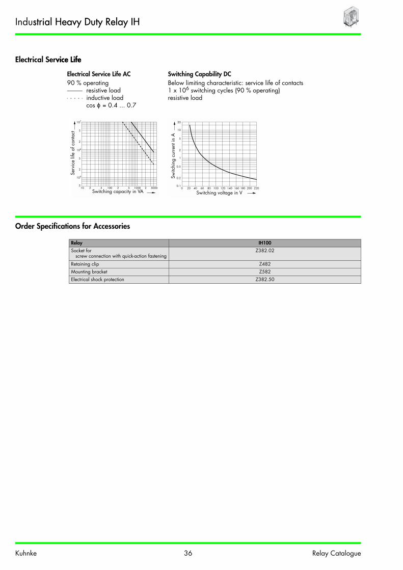
Electrical Service Lifevice Life
Electrical Service Life AC Switching Capability DC90 % operating Below limiting characteristic: service life of contacts
resistive load 1 x 10⁶ switching cycles (90 % operating)inductive load resistive loadcos ϕ = 0.4 ... 0.7
Order Specifications for Accessories
Relay IH100
Socket for screw connection with quick-action fastening
Z382.02
Retaining clip Z482Mounting bracket Z582Electrical shock protection Z382.50
10 2 5 2 5 2 5000100 10005
2
5
105
106
107
2
5
Serv
ice
life
of c
onta
ct
Switching capacity in VA0 20 40 60 80 100 120 140 160 180 200 220
0.1
0.5
1
0.2
5
10
20
2
Switc
hing
cur
rent
in A
Switching voltage in V
Industrial Heavy Duty Relay IHstrial Heavy Duty Relay IH

Kuhnke 377 Relay Catalogue
Socket Z382.022.02
Mounting Bracket Z582
Socket Z382.02382.02
Socket designTerminal capacityminal capacity solid conductor flexible conductor with ferrule
2 x 2.5 mm2
2 x 1.5 mm2
Terminal designation in accordance with EN50005Mounting Rail EN50022-35 x 7.5/15Screw terminals Head screws metric M4Torque in accordance with DIN EN 60999 1.2 NmNominal current 6 AInsulation group VDE 0110b/2.79 C250Electrical shock protection Electrical shock protection optional 2 x Z382.50Weight 105 gRetaining clip Z482
Z582
Mounting with screw M3 to relayWeight approx. 11 g
Shown with electrical shock protections (2 x Z382.50)
Z382.0267
3972
A1
A2 22 21 24 42 41 44
12 11 14 32 31 34
3022.515
2 3.2
154
Accessories for Industrial RelayRelay

Kuhnke 38 Relay Catalogue
Relay-Contactor 105
• Standard type , ,• Mechanically guided contacts for security controls
in accordance with DIN VDE 0113 part 1• High switching capability through bridge contacts• High contact making reliability
through twin contacts• Version for printed circuit
Order Code
Order code 105 A 400 – 24 V DC
Type of relay 105Model
A Plug-in type for socket 6.3 mm or 2 x B 2.8 resp. in accordance with DIN 46247
A
G For printed circuit GContact arrangement
400 4 N/O 400310 3 N/O, 1 N/C 310220 2 N/O, 2 N/C 220
Contact material, type of contact- Hard silver (no code letter) -C AgCdO (model A only) CF Twin contacts hard silver F
Nominal operation coil voltage (see coil data)24 V 24 V
Coil current typeDC Direct current DCAC Alternating current 50 / 60 Hz
with bridge rectifierbridge rectifierAC
Extensions- None (no code letter) -B Quick-action fastening for rail
EN50022-35 x 7.5B
H Manual override(combination B and H not possible)
H
S Screw mounting S
+S
Made in Germany
105A31024VDC
Uc:
VDE 0660
+S
027
A 30010A 300VAC15A 150VAC
Ith2=16A Ui=380Vac (C)
380VAC 2,2kW AC3
380VAC 6kW AC1
Relay-ContactorMade in Germany
105A31024VDC
Uc:
VDE 0660
+S
027
A 30010A 300VAC15A 150VAC
Ith2=16A Ui=380Vac (C)
380VAC 2,2kW AC3
380VAC 6kW AC1

Kuhnke 39 Relay Catalogue
Contact Data
Dimensions, Connection Diagram(s)gram(s)
105A ... B 105G ... H 105A ... S
105 ... 400 105 ... 310 105 ... 220
Viewed on connector pinsDrillhole diameter 2.1 mm
105
Contact arrangement 4 N/O3 N/O and 1 N/C2 N/O and 2 N/C
Contact arrangement Single contact Control contactType of contactype of contact Bridge contact Bridge contact as twin contactContact material Hard silver
AgCdOHard silver
Nominal contact current 16 A 10 AInrush current ≤ 60 A ≤ 20 A Nominal contact voltage 400 VAC / DCMax. switching capacity (resistive) 6000 VA 3000 VAMin. switching capacity 200 mA / 60 VDC 50 mA / 20 VDCSwitching capacity AC1
AC36 kW / 400 V
2.2 kW / 400 V3 kW / 400 V
0.75 kW / 400 V
DC1AC4
100 W (for security circuit in accordance with professional association) not suitable
20
39
62.5
625
62.5
57.5
2
20
39
59.5
11
1
20
4.5
39
50
60
4562.5
25
A1
A2
13
14
23
24
33
34
43
44
A1
A2
13
14
23
24
33
34
41
42
A1
A2
13
14
23
24
31
32
41
42
Grid 2.5 mm
Relay-ContactorMade in Germany
105A31024VDC
Uc:
VDE 0660
+S
027
A 30010A 300VAC15A 150VAC
Ith2=16A Ui=380Vac (C)
380VAC 2,2kW AC3
380VAC 6kW AC1

Kuhnke 40 Relay Catalogue
General Data
Coil Data
105
Pull-in-time approx. 25 ms Drop-out time approx. 8 ms DC, approx. 35 ms ACBounce time approx. 5 ms Mechanical service life > 10 x 106 switching cycles
Test voltageCoil - contact 2500 VACContact - contact 2500 VAC
Insulation group VDE 0110b/2.79 C380Short-circuit protection VDE 0660 part 200 1000 AAmbient temperature -25 °C to +60 °CVibration resistance (30 - 100 Hz) > 4 g 4 g Weight approx. 260 g Operating range DC
Class 2 (0.85 - 1.1 UN)
AC, 50 / 60 HzClass 2
(0.85 - 1.1 UN)
Pull-in after coil excitationwith UN at TU 35 °C
Drop-out > 0.05 UN > 0.15 UN
Coil voltageDC*
*Other voltages on request
105Pull-in power approx. 1.3 W
Nom. operation coil power approx. 3.6 W
Coil voltageAC*
105Pull-in power approx. 1.5 VA
Nom. operation coil power approx 4.2 VA.
Nominal voltage (V) Nom. resistance (Ω) Nominal current (mA) Nominal voltage (V) Nom. resistance (Ω) Nominal current (mA)
12 41 290 12 32 34024 151 160 24 120 18040 473 85 42 390 9760 968 62 60 780 69
110 3370 33 110 2710 37220 13700 16 230 13400 15
Relay-ContactorMade in Germany
105A31024VDC
Uc:
VDE 0660
+S
027
A 30010A 300VAC15A 150VAC
Ith2=16A Ui=380Vac (C)
380VAC 2,2kW AC3
380VAC 6kW AC1

Kuhnke 41 Relay Catalogue
Electrical Service Life
Electrical Service Life AC 190 % operating
400 V230 V
Single contacts Control contacts
Electrical Service Life AC 390 % operating
400 V230 V
Single contacts Control contacts
Switching Capability DC 190 % operating
Single contact closing contact Single contact opening contact
0.1 0.2 0.5 2 5 1015
2
5
2
5
105
106
107
AC 1
3600 S/h
Resistance switching capacity in kW
Serv
ice
life
of c
onta
ct
0.1 0.2 0.5 2 5 1015
2
5
2
5
105
106
107
AC 1
3600 S/h
Resistance switching capacity in kW
Serv
ice
life
of c
onta
ct
0.1 0.2 0.5 2 5 1015
2
5
2
5
105
106
107
AC 3
3600 S/hM3~
Motor switching capacity in kW
Serv
ice
life
of c
onta
ct
0.1 0.2 0.5 2 5 1015
2
5
2
5
105
106
107
AC 3
3600 S/hM3~
Motor switching capacity in kW
Serv
ice
life
of c
onta
ct
DC 1
Closing contact
DC 1
Closing contact
0 280240200160 220 260120 1801401004020 8060 3000.1
0.2
0.5
1
2
5
10
20
Switch-off voltage in Vvoltage in V
Switc
hing
cur
rent
in A
0 280240200160 220 260120 1801401004020 8060 3000.1
0.2
0.5
1
2
5
10
20
DC 1
Openingcontact
DC 1
Opening contact
Switc
hing
cur
rent
in A
Switch-off voltage in V
Relay-ContactorMade in Germany
105A31024VDC
Uc:
VDE 0660
+S
027
A 30010A 300VAC15A 150VAC
Ith2=16A Ui=380Vac (C)
380VAC 2,2kW AC3
380VAC 6kW AC1

Kuhnke 42 Relay Catalogue
Order Specifications for Accessoriesder Specifications for Accessories
Socket Z320.02
Relay 105
Socket for scew connection with quick-action fastening Z320.02
Socket Z320.02
Terminal capacity solid conductor flexible conductor with ferrule
2 x 2.5 mm2
2 x 1.5 mm2
Terminal designation in accordance with EN50005Mounting Rail EN50022-35 x 7.5/15Screw terminals Head screws metric M4Torque in accordance with DIN EN 60999 1.2 NmNominal current 16 AInsulation group VDE 0110b/2.79 C380Weight 110 gRetaining clip enclosed retaining clips
64
27.5
571
Relay-ContactorMade in Germany
105A31024VDC
Uc:
VDE 0660
+S
027
A 30010A 300VAC15A 150VAC
Ith2=16A Ui=380Vac (C)
380VAC 2,2kW AC3
380VAC 6kW AC1

Kuhnke 43 Relay Catalogue
Power Relay P
• Specify design in your order• 1 bridge contact for 50 A• With blow-out magnet for switching
high DC loads• Auxiliary contact as control contact possible
Order Code
Contact Data
Order code P A S – 24 V DC
Type of relayPower relay P
Contact arrangementA 1 N/O AR 1 N/C R
Contact material single contact (main contact)S Hard silver SC AgCdO (model A only) CW Tungsten W
Contact material auxiliary contact- Without auxiliary contact (no code letter) -S Hard silver S
Nominal operation coil voltage (see coil data)24 V 24 V
Coil current typeDC Direct current DCAC Alternating current 50 Hz (60 Hz on request) AC
Extensions- None (no code letter) -B Quick-action fastening for rail
EN50022-35 x 7.5 B
M Blow-out magnet only with N/O contact M
P
Contact arrangement Single contact (main contact) Auxiliary contactType of contact Bridge contact Single contactContact material Hard silver AgCdO Tungsten Hard silverNominal contact current 50 A 50 A 10 A 6 AInrush current ≤ 100 A ≤ 200 A ≤ 300 A ≤ 6 ANominal contact voltage 400 VAC / DC 250 VACMax. switching capacity(resistive)
4000 VA 100 VA
Min. switching capacity 500 mA / 60 VDC - 50 mA / 20 VDC
+S
Power Relay

Kuhnke 44 Relay Catalogue
Dimensions, Connection Diagram(s)
I Auxiliary contactII Blow-out magnetIII Quick-action fastening
General Data
Coil Data
P
Pull-in -time approx. 30 ms Drop-out time approx. 20 msBounce time approx. 8 ms Mechanical service life > 5 x 10⁶ switching cycles DC
> 2 x 10⁶ switching cycles ACTest voltage
Coil - contact 2500 VACContact - frame 2500 VACAuxiliary contact - frame 2000 VAC
Insulation group VDE 0110b/2.79 C380 single contact (main contact)C125, B250 coil and auxiliary contact
Ambient temperature -25 °C to +60 °C DC-25 °C to +40 °C AC
Vibration resistance (30 - 100 Hz) > 5 g N/O contact> 2 g N/C contact
Weight approx. 220 g Operating range DC
Class 1 (0.8 - 1.1 UN)
AC, 50 HzClass 1
(0.8 - 1.1 UN)
Pull-in after coil excitationwith UN at TU 20 °C 20 °C
Drop-out > 0.05 UN > 0.15 UN
Coil voltage*
DC
*Other voltages on request
PPull-in power approx. 1.3 W
Nominal operation coil power approx. 3.0 W
Coil voltage AC50 Hz
PInrush current approx. 1.4 x nominal current
Nominal operation coil power 9.5 VA
Nominal voltage (V) Nom. resistance (Ω) Nominal current (mA) Nominal voltage (V) Nom. resistance (Ω) Nominal current (mA)
12 55 220 12 2.94 68024 193 120 24 11.2 37040 528 76 42 35.1 22060 1250 48 60 64.7 160
110 3670 30 110 245 87220 15000 15 230 1170 41
5314
15
45
M3
II
I
29.5
4.5
M5
61.5
56
III
Power Relay

Kuhnke 45 Relay Catalogue
Electrical Service LifeElectrical Service Life AC Switching Capability DC
without blow-out magnet90 % operation Below limiting characteristic: service life of contacts
resistive load 1 x 10⁶ switching cycles (90 % operation)inductive load resistive loadcos ϕ = 0.4 ... 0.7
Electrical Service Life DCwith blow-out magnet, resistive load
Electrical Service Life ACAuxiliary contact
Switching current(A)
Voltage(V)
Service lifeswitching cycles approx.
2 220 5 x 10⁶
5 5 x 10⁶
10 0.5 x 10⁶
Switching capacity(VA)
Service lifeswitching cycles approx.
100 5 x 10⁶
10 2 5 2 5 2 5000100 10005
2
5
105
106
107
2
5
Switching capacity in VA
Serv
ice
life
of c
onta
ct
0 20 40 60 80 100 120 140 160 180 200 2201
5
10
2
50
80
20
Switc
hing
cur
rent
in A
Switching voltage in V
Power Relay

Kuhnke 46 Relay Catalogue
Process Relay Analogue to Digital Converter PZ 610 / PZ 6200 / PZ 620
• Standard housing, 22.5 mm wide• Alternatively with relay or transistor output• CE symbol
Order Code
General Data
Order code PZ 610 - 1 - 230 / 24 VAC
Process relayPZ PZ
Function610 Analogue to digital converter
with relay output610
620 Analogue to digital converterwith transistor output as C/O
620
Output1 C/O 1
Supply voltage24 VDC 24 VDC230 / 24 VAC 230 / 24 VAC
PZ 610 / PZ 620
Display green LED supply voltage availableyellow LED, relay switched on
Insulation class to VDE 0110b/2.79 C250
Test voltageInput - supply - output 3750 VAC
Terminals Twin tension relief terminals with head screws metric M3Terminal torque in accordance withDIN EN 60999
0.5 Nm
Terminal capacitysolid conductorflexible conductor with ferrule
2 x 2.5 mm2
2 x 1.5 mm2
Operating temperature -20 °C to +55 °C+55 °CStorage temperature -40 °C to +80 °CProtection in accordance with DIN 40050 IP 20Mounting Rail in accordance with EN50022-35 x 7.5/15Weight approx. 180 g
Process Relay 600

Kuhnke 47 Relay Catalogue
Dimensions, Connection Diagram(s), Functional Diagrammensions, Connection Diagram(s), Functional Diagram
Contact Data Output
Supply Circuit
Signal Input
Bridge Function
F - R Relay inversion
F - X Memory function
PZ 610 PZ 620
Contact arrangement 1 C/O, relay 1 C/O, transistorType of contact Single contact –Contact material AgNi –Nominal contact current 8 A 100 mANominal contact voltage 250 V ±35 VDC / 24 VACMax. switching capacity 2000 VA
PZ 610 PZ 620
Supply voltage 24 VDC (0.85 - 1.15 x U(0.85 - 1.15 x UN)230 / 24 VAC (0.85 - 1.1 x UN)
Line frequency 45 - 65 HzNominal coil power AC; 3 VA
DC; 2 W
PZ 610 PZ 620
Analogue input, select at front panel, adjust via potentiometer
0 - 5 VDC, 0 - 10 VDC, -10 to +10 VDC0 to 20 mA, 4 to 20 mA
Impedance Voltage: 100 kΩCurrent: 50 Ω
Upper frequency limit 30 Hz
Hysteresis adjustable via front panel ±0.5 to ±20 %
104
80
22.5
0in
A1 11 X
A3 F R
11
1412
12 14 A2
I in Uin
0in I in Uin
A1 A2 A3
230 VAC
24 VDC24 VAC
NN-
0in
A1 NC X
A3 F R
NO A2com
A1 A2 A3
I in Uin
0in I in Uin
NC
com
NO
230 VAC
24 VDC24 VAC
NN-
PZ 620
Process Relay 600
PZ 610

Kuhnke 48 Relay Catalogue
Process Relay Analogue to Analogue Converter PZ 630
• Standard housing, 22.5 mm wide• Analogue inputs galvanically separated• CE symbol
Order Code
General Data
Order code PZ 630 - 2 - 230 VAC
Process relayPZZ PZ
Function630 Analogue to analogue
converter630
Output2 Analogue output 2
Supply voltage24 VDC 24 VDC230 VAC 230 VAC
PZ 630
Display Green LED supply voltage availableYellow LED, input < 5 % of limiting value
Insulation class to VDE 0110b/2.79 C250
Test voltage 3750 VAC Terminals Twin tension relief terminals with head screws metric M3M3Terminal torque in accordance with DIN EN 60999
0.5 Nm
Terminal capacitysolid conductorflexible conductor with ferrule
2 x 2.5 mm2
2 x 1.5 mm2
Operating temperature -20 °C to +55 °CStorage temperature -40 °C to +80 °CProtection in accordance with DIN 40050 IP 20Mounting Rail in accordance with EN50022-35 x 7.5/15Weight approx. 170 g
PZ63
0
Signal Converter
PZ630
PZ 630-2-230VAC
EUROPEAN TECHNOLOGY
4 0
0
03
3
7
72
2
5
1
4
Z1Z2
0inI in
Uin
A1A2
0outI out
Uout
Z1Z2
0in I out
Uout
0out
I inUin
Offset
Gain
A1 A2
230 VAC N
Process Relay 600

Kuhnke 49 Relay Catalogue
Dimensions, Connection Diagram(s)
Output Circuit
Supply Circuity Circuit
Signal Input
Output Bridge PZ 630
Output selectable via terminalsvia terminals 0out - Iout0out - Iout0out - Uout
–Z1 - Z2Z1 - Z2
Uout and Iout bridged
4 - 20 mADC (max. 500 Ω)0 - 20 mADC (max. 500 Ω)
0 - 10 VDC (int. shunt 500 Ω)
Accuracy of setting < 1 %Linearity < 0.05 % in relation to maximum scale
value
Temperature coefficient 0.02 %/°C
PZ 630
Supply voltage A1(+) - A2(-)A1(L) - A2(N)
24 VDC (0.85 - 1.15 x UN)230 VAC (0.85 - 1.1 x UN)
Line frequency 45 - 65 HzNominal coil power AC; 3 VA
DC; 2 W
PZ 630
Analogue input, select at front panel 0in - Uin0in - Iin
0 - 5 VDC, 0 - 10 VDC, -10 to +10 VDC0 to 20 mA, 4 to 20 mA
Impedancedance Voltage: 100 kΩCurrent: 50 Ω
Upper frequency limit 30 Hz
Offset (zero / span) and amplification adjustable via front panel
±0.5 %
104
80
22.5
Z1 Z2
0in I in Uin
A1 A2
0out I out Uout
Z1Z2
0in
I outUout
0out
I in Uin
Offset Gain
A1 A2
230 VAC
24 VDC
N
-
Process Relay 600

Kuhnke 500 Relay Catalogue
Process Relay PT-100 with Analogue Output PZ 640h Analogue Output PZ 640
• Standard housing, 22.5 mm wide• LED indicator for sensor error• For sensors from -50 °C to 300 °C• CE symbol
Order CodeCode
General Data
Order code PZ 640 - 2 - 230 VAC
Process relayPZ PZ
Function640 PT-100 Analogue converter 640
Output2 Analogue output 2
Supply voltage24 VDC 24 VDC230 VAC 230 VAC
PZ 640
Display Green LED supply voltage availableYellow LED, input < 5 % of limiting value
Insulation class to VDE 0110b/2.79 C250
Test voltage 3750 VAC Terminals Twin tension relief terminals with head screws metric M3Terminal torque in accordance withDIN EN 60999
0.5 Nm
Terminal capacitysolid conductorflexible conductor with ferrule
2 x 2.5 mm2
2 x 1.5 mm2
Operating temperature -20 °C to +55 °CStorage temperature -40 °C to +80 °C40 °C to +80 °CProtection in accordance with DIN 40050 IP 20Mounting Rail in accordance with EN50022-35 x 7.5/15Weight approx. 170 g
Process Relay 600

Kuhnke 51 Relay Catalogue
Dimensions, Connection Diagram(s)
Output Circuit
Supply Circuity Circuit
Signal Input
Output Bridge PZ 640
Output selectable via terminals 0out - Iout0out - Iout0out - Uout
–Z1 - Z2Z1 - Z2
4 - 20 mADC (max. 500 Ω)0 - 20 mADC (max. 500 Ω)
0 - 10 VDC (max. 5 mA) internal 500 Ω shunt
Accuracy of setting < 1 %%Linearity < 0.05 % in relation to maximum scale valueTemperature coefficient 0.02 %/°C
PZ 640
Supply voltage A1(+) - A2(-)A1(L) - A2(N)
24 VDC (0.85 - 1.15 x UN)230 VAC (0.85 - 1.1 x UN)
Line frequency 45 - 65 HzNominal coil power AC; 3 VA
DC; 2 W
PZ 640
Analogue input, select at front panel. For 2 or 3-wire PT-100 resistorsPT-100 resistors
–F - T2
-50 °C to 300 °C-50 °C to 100 °C
104
80
22.5
Z1 Z2 F
T0 T1 T2
A1 A2
Z1Z2
T0
F
I out
T1 T2
0out I out Uout
Uout
0out
PT 100
A1 A2
230 VAC
24 VDC
N
-
Process Relay 600

Kuhnke 52 Relay Catalogue
Process Relay Analogue Frequency Converter PZ 650Z 650
• Standard housing, 22.5 mm wide• Connects to PLCs with digital counter inputs• CE symbol
Order Code
General Data
Order code PZ 650 - 21 - 230
Process relayPZ PZ
Function650 Analogue frequency converter 650
Output21 Analogue output
0 - 50 Hz / 0 - 5 KHz / 0 - 10 KHz
21
22 Analogue output 0 - 40 Hz / 0 - 4 KHz /0 - 8 KHz
22
Supply voltage24 VDC 24 VDC230 VAC 230 VAC
PZ 650
Display Green LED supply voltage availableYellow LED, Input < 5 % of limiting valuemiting value
Insulation class to VDE 0110b/2.79 C250
Test voltage 3750 VAC Terminals Twin tension relief terminals with head screws metric M3Terminal torque in accordance withDIN EN 60999
0.5 Nm
Terminal capacitysolid conductorflexible conductor with ferrule
2 x 2.5 mm2
2 x 1.5 mm2
Operating temperature -20 °C to +55 °CStorage temperature -40 °C to +80 °CProtection in accordance with DIN 40050 IP 20Mounting Rail in accordance with EN50022-35 x 7.5/15Weight approx. 170 g
Process Relay 600

Kuhnke 53 Relay Catalogue
Dimensions, Connection Diagram(s)ction Diagram(s)
Output Circuit
The output is capable of controlling both PNP and NPN inputs.The +/- polarity is to be observed./- polarity is to be observed.
Supply Circuit
Signal Input
Output Bridge PZ 650
Output frequency50 % impulse-to-interval ratio
out + – out -Z1 - Z2Z1 - Z3
0 - 8 / 0 - 10 KHz; Umax -35 V; Imax -100 mA0 - 4 / 0 - 5 KHz; Umax -35 V; Imax -100 mA0 - 40 / 0 - 50 Hz; Umax -35 V; Imax -100 mA
Switch-on time 50 % (40 - 60 %)Accuracy of setting < 1 %Linearity < 0.05 % in relation to maximum scale valueTemperature coefficient 0.02 %/°C°C
PZ 650
Supply voltage A1(+) - A2(-)A1(L) - A2(N)
24 VDC (0.85 - 1.15 x UN)230 VAC (0.85 - 1.1 x UN)
Line frequency 45 - 65 HzNominal coil power AC; 3 VA
DC; 2 W
PZ 650
Analogue input, select at front panel Offset (zero / span) and amplification adjustable via front panel
0in - Uin0in - Iin
0 - 5 VDC, 0 - 10 VDC, -10 to +10 VDC0 to 20 mA, 4 to 20 mA
Impedance Voltage: 1 MMΩCurrent: 50 Ω
104
80
22.5
A1 A2
out +
out- out+
I in Uin
Z1 Z2 Z3
0in Uin I
Z1 Z2 Z3
in
out -
0in
A1 A2
230 VAC
24 VDC
N
-
Process Relay 600

Kuhnke 54 Relay Catalogue
Process Relay Frequency Analogue Converter PZ 660Relay Frequency Analogue Converter PZ 6600
• Standard housing, 22.5 mm wide• CE symbol
Order Code
General Data
Order code PZ 660 - 2 - 230 VAC
Process relayPZ PZ
Function660 Frequency analogue converter 660
Output2 Analogue output 2
Supply voltage24 VDC 24 VDC230 VAC 230 VAC
PZ 660
Display Green LED supply voltage availableYellow LED, input < 5 % of limiting value
Insulation class to VDE 0110b/2.799 C250
Test voltage 3750 VAC Terminals Twin tension relief terminals with head screws metric M3Terminal torque in accordance with DIN EN 60999
0.5 Nm
Terminal capacitysolid conductorflexible conductor with ferrule
2 x 2.5 mm2
2 x 1.5 mm2
Operating temperature -20 °C to +55 °CStorage temperature -40 °C to +80 °CProtection in accordance with DIN 40050 IP 20Mounting Rail in accordance with EN50022-35 x 7.5/15Weight approx. 170 g
Process Relay 600

Kuhnke 55 Relay Catalogue
Dimensions, Connection Diagram(s)
Output Circuit
Supply Circuit
Signal Input
NPN, PNP and Namur signals with a maximum current consumption of 10 mA can be connected.A can be connected.
Output Bridge PZ 660
Output signalselectable via terminals
0out - Iout0out - Iout0out - Uout
–Z1 - Z2Z1 - Z2
4 - 20 mADC0 - 20 mADC
0 - 10 VDC (via internal 500 Ω shunt)
Accuracy of setting < 1 %Linearity < 0.05 % in relation to maximum scale valueTemperature coefficient 0.02 %/°COffset voltage and amplification selectable via front panel
±5 %
PZ 660
Supply voltage A1(+) - A2(-)A1(L) - A2(N)
24 VDC (0.85 - 1.15 x UN)230 VAC (0.85 - 1.1 x UN)
Line frequencyquency 45 - 65 HzNominal coil power AC; 3 VA
DC; 2 W
PZ 660
Frequency input selectable via front panel 0 - 100 Hz, 0 - 500 Hz, 0 - 1 KHz, 0 - 2 KHz, 0 - 5 KHz
104
80
22.5
A1 A2
–
Z1 Z2PNPNamur
NPN
+ –
+
Iout Uout0out
A1 A2
230 VAC
24 VDC
N
–
Z1Z2I outUout
0out
Process Relay 600

Kuhnke 56 Relay Catalogue
Single-phase Voltage Monitoring Relay U 510 / U 5110 / U 511
• Standard housing, 22.5 mm wide• Selectable memory function• Analogue output for switching point adjustment• Test voltage 3750 VAC
Order Code
General Data
Order code U 510. 1 – 230 / 24 VAC
Single-phase voltageU U
Monitored variable510 Undervoltage 510.511 Overvoltage 511.
Contact arrangement1 C/O 1
Supply voltage24 VDC 24 VDC115/24 VAC 115 / 24 VAC230/24 VAC 230 / 24 VAC
U 510 / U 511
Display Green LED "Supply On"Red LED error, relay droped-out
Insulation group VDE 0110b/2.79 C250Test voltage 3750 VACTerminals Twin tension relief terminals with head screws metric M3Terminal torque in accordance withDIN EN 6099960999
0.5 Nm
Terminal capacity
solid conductor 2 x 2.5 mm2
flexible conductor with ferrule 2 x 1.5 mm2
Operating temperature -20 °C to +55 °CStorage temperature -40 °C to +80 °CProtection in accordance with DIN 40050 IP 20Mounting Rail in accordance with EN50022-35 x 7.5/15Weight approx. 180 g
A3
S
X12
14A2
A111
RB1
U 5
11
B2
X
- inverse re
lay
- latch
- 0-10V DC (setpoint)
S
B2Hyst.
Set
point
B1
R
Single Phase Under Voltage
U 511 - 230/24 V AC
EUROPEAN TECHNOLOGY
33/9
7
>U
11
1214
250V AC
8 A
A3
A1 A2
24
VAC230
VACN
Monitoring Relay 500500 A3
S
X12
14A2
A111
RB1
U 5
11
B2
X
- inverse re
lay
- latch
- 0-10V DC (setpoint)
S
B2Hyst.
Set
point
B1
R
Single Phase Under Voltage
U 511 - 230/24 V AC
EUROPEAN TECHNOLOGY
33/9
7
>U
11
1214
250V AC
8 A
A3
A1 A2
24
VAC230
VACN

Kuhnke 57 Relay Catalogue
Dimensions, Connection Diagram(s), Functional Diagramsction Diagram(s), Functional Diagrams
U 51010 U 511
Contact Data
Auxiliary Circuit
Monitoring Circuit
Bridge Function
B1 - R Relay inversion
B1 - X Latch
B1 - S Settinganalogous to
2 - 10 V
U 510 / U 511
Contact arrangement 1 C/OType of contact Single contactContact material AgNi, gold-platedNominal contact current 8 ANominal contact voltage 250 VAC / 24 VDCMax. switching capacity 2000 VA / 100 W
Supply voltage A1 (+) - A2 (-)A3 - A2 (N)A1 - A2 (N)A1 - A2 (N)
24 VDC24 VAC (45 - 65 Hz)
115 VAC (45 - 65 Hz)230 VAC (45 - 65 Hz)
Overload rating 1.15 x UUN continuous
Rated power DC 2 WAC 3 VA
U 510 U 511
Monitored voltage (B1 - B2)to B2 at DC+
1 - 500 VAC / DC in 5 ranges, selectable via "Range"1 - 5 V / 4 - 20 V / 10 - 50 V / 40 - 200 V / 100 - 500 V
Input impedance 500 kΩU max 700 VACDrop-out adjustable in chosen range -
dropping voltageadjustable in chosen range -
rising voltage
Pull-in 0.5 - 20 % of chosen range limit, adjustable above drop-out value
0.5 - 20 % of chosen range limit, adjustable below drop-out value
Temperature dependence ≤ 0.05 %/KSetting of switching point B1: + on S 2 - 10 V analogous to switching point (drop-out value)Latch of bridge B1 - x If the relay drops out after error, reenergizing is only possible after opening the bridge or
interrupting the supply voltage.
104
80
22.5
230VAC
24VACN
B1 B2
A1 11 R
A3 S X
12
250 V AC8 A
11
14
12 14 A2
B2
RX
S
A1A2 A3
Setpoint > U
Hyst.
B1
Monitoring Relay 500ay 500 A3
S
X12
14A2
A111
RB1
U 5
11
B2
X
- inverse re
lay
- latch
- 0-10V DC (setpoint)
S
B2Hyst.
Set
point
B1
R
Single Phase Under Voltage
U 511 - 230/24 V AC
EUROPEAN TECHNOLOGY
33/9
7
>U
11
1214
250V AC
8 A
A3
A1 A2
24
VAC230
VACN

Kuhnke 58 Relay Catalogue
Three-phase Voltage Monitoring Relay UD 517 / UD 532hree-phase Voltage Monitoring Relay UD 517 / UD 5327 / UD 532
• Standard housing, 22.5 mm wide• Selectable memory function• Test voltage 3750 VAC
Order Code
General Datata
Order code UD 517. 1 – 230 / 400 45 - 65 Hz
Three-phase voltageUD UD
Monitored variable517 Three-phase - undervoltage
- overvoltage517.
532 Three-phase - undervoltage- asymetric angle- sequence
532.
Contact arrangement1 C/O 1
Supply voltage(Voltage: Phase - N / Phase - PhaseSupply voltage.measuring voltage)
230 / 400 VAC (UD532 only) 230 / 400 230 VAC 230.400400 VAC 400.400
Frequency47 - 53 Hz (UD532 only) 47 - 53 Hz45 - 65 Hz (UD517 only)65 Hz (UD517 only) 45 - 65 Hz
UD 517 UD 532
Display Upper red LED overvoltageLower red LED undervoltage
Green LED "Supply On"Red LED error, relay droped-out
Insulation group VDE 0110b/2.79 C250Test voltage 3750 VACTerminals Twin tension relief terminals with head screws metric M3M3Terminal torque in accordance with DIN EN 60999 0.5 NmTerminal capacity
solid conductor 2 x 2.5 mm2
flexible conductor with ferrule 2 x 1.5 mm2
Operating temperature -20 °C to +55 °CStorage temperature -40 °C to +80 °CProtection in accordance with DIN 40050 IP 20Mounting Rail in accordance with EN50022-35 x 7.5/15Weight approx. 180 g
A3
S
X12
14A2
A111
RB1
U 5
11
B2
X
- inverse re
lay
- latch
- 0-10V DC (setpoint)
S
B2Hyst.
Set
point
B1
R
Single Phase Under Voltage
U 511 - 230/24 V AC
EUROPEAN TECHNOLOGY
33/9
7
>U
11
1214
250V AC
8 A
A3
A1 A2
24
VAC230
VACN
Monitoring Relay 500Relay 500 A3
S
X12
14A2
A111
RB1
U 5
11
B2
X
- inverse re
lay
- latch
- 0-10V DC (setpoint)
S
B2Hyst.
Set
point
B1
R
Single Phase Under Voltage
U 511 - 230/24 V AC
EUROPEAN TECHNOLOGY
33/9
7
>U
11
1214
250V AC
8 A
A3
A1 A2
24
VAC230
VACN

Kuhnke 59 Relay Catalogue
Dimensions, Connection Diagram(s), Functional Diagrams
Bridge X1 - X2 = LatchX1 - X2 = LatchUD517 UD532
UD517 UD532
Contact Data
UD 517 / UD 532
Contact arrangement 1 C/OType of contact Single contact Contact material AgNi gold-platedNominal contact current 8 ANominal contact voltage 250 VAC Max. switching capacity 2000 VA
104
80
22.5
L3
X2X1
A2A1
L1 L2 L3
A1 11 N
X1 X2
12
250 V AC8 A
11
14
12 14 A2
U><
NL1 L2 L3L3L2
L1 L2 L3
11 N
12
11
14
12 14
NL1 L2
Monitoring Relay 500ring Relay 500 A3
S
X12
14A2
A111
RB1
U 5
11
B2
X
- inverse re
lay
- latch
- 0-10V DC (setpoint)
S
B2Hyst.
Set
point
B1
R
Single Phase Under Voltage
U 511 - 230/24 V AC
EUROPEAN TECHNOLOGY
33/9
7
>U
11
1214
250V AC
8 A
A3
A1 A2
24
VAC230
VACN

Kuhnke 60 Relay Catalogue
Auxiliary Circuit
Monitoring Circuit
UD 517 UD 532
to A1 / A2 230 or 400 V 45 to 65 Hzor by bridge to monitoring inputby bridge to monitoring input
internally connected to monitored voltage L2 / L3
UD 517 UD 532
Nominal line voltages 230 / 400 V (N required)
Nominal line frequency 45 - 65 Hz 47 - 53 HzOverload rating 1.2x UN continuousRated power 3 VA cos ϕ ≈ 0.7
Drop-out
Adjustment error
Uab of 1.01 - 1.20 x UN and0.80 - 0.99 x UN
adjustable
≤ 3 %
Nominal voltage selectable between 340 and 460 V. As permanently set to 20°
Undervoltage adjustable between 0.6 to 0.98 x UN
Pull-in Hysteresis fixed setting at 2 % approx. fixed setting at 1 % approx.Memory function One error noneTemperature dependence ≤ 0.05 %/K
Monitoring Relay 500500 A3
S
X12
14A2
A111
RB1
U 5
11
B2
X
- inverse re
lay
- latch
- 0-10V DC (setpoint)
S
B2Hyst.
Set
point
B1
R
Single Phase Under Voltage
U 511 - 230/24 V AC
EUROPEAN TECHNOLOGY
33/9
7
>U
11
1214
250V AC
8 A
A3
A1 A2
24
VAC230
VACN

Kuhnke 61 Relay Catalogue
Single-phase Current Monitoring Relay I 540 / I 5410 / I 541
• Standard housing, 22.5 mm wide• Selectable memory function• Analogue output for setting the switching point• Test voltage 3750 VAC
Order Code
General Data
Order code I 540. 1 – 230 / 24 VAC
Single-phase currentI I
Monitored variable540 Undercurrent 540.541 Overcurrent 541.
Contact arrangement1 C/O 1
Supply voltage24 VDC 24 VDC115 / 24 VAC 115 / 24 VAC230 / 24 VAC 230 / 24 VAC
I 540 / I 541
Display Green LED "Supply On"Red LED error, relay droped-out
Insulation group VDE 0110b/2.79 C250Test voltage 3750 VACTerminals Twin tension relief terminals with head screws metric M3Terminal torque in accordance withDIN EN 60999N EN 60999
0.5 Nm
Terminal capacity
solid conductor 2 x 2.5 mm2
flexible conductor with ferrule 2 x 1.5 mm2
Operating temperature -20 °C to +55 °CStorage temperature -40 °C to +80 °CProtection in accordance with DIN 40050 IP 20Mounting Rail in accordance with EN50022-35 x 7.5/15Weight approx. 180 g
A3
S
X12
14A2
A111
RB1
U 5
11
B2
X
- inverse re
lay
- latch
- 0-10V DC (setpoint)
S
B2Hyst.
Set
point
B1
R
Single Phase Under Voltage
U 511 - 230/24 V AC
EUROPEAN TECHNOLOGY
33/9
7
>U
11
1214
250V AC
8 A
A3
A1 A2
24
VAC230
VACN
Monitoring Relay 500ay 500 A3
S
X12
14A2
A111
RB1
U 5
11
B2
X
- inverse re
lay
- latch
- 0-10V DC (setpoint)
S
B2Hyst.
Set
point
B1
R
Single Phase Under Voltage
U 511 - 230/24 V AC
EUROPEAN TECHNOLOGY
33/9
7
>U
11
1214
250V AC
8 A
A3
A1 A2
24
VAC230
VACN

Kuhnke 622 Relay Catalogue
Dimensions, Connection Diagram(s), Functional Diagramssions, Connection Diagram(s), Functional Diagrams
I 540 I 541
Contact Data
Auxiliary Circuit
Monitoring Circuit
Bridge Function
B1 - R Relay inversion
B1 - X Latch
B1 - S Setting analogous to
2 - 10 V
I 540 / I 541
Contact arrangement 1 C/OType of contact Single contactContact material AgNi, gold-platedNominal contact current 8 ANominal contact voltage 250 VAC / 24 VDCMax. switching capacity 2000 VA / 100 W
Supply voltage A1 (+) - A2 (-)A3 - A2 (N)A1 - A2 (N)A1 - A2 (N)
24 VDC24 VAC (45 - 65 Hz)z)
115 VAC (45 - 65 Hz)230 VAC (45 - 65 Hz)
Overload rating 1.15 x UN continuous
Rated power DC 2 WAC 3 VA
I 540 I 541
Monitored current (B1 - B2 - B3)(B1 - B2)(B1 - B3)
4 mA - 2 A DC/AC in 5 ranges, selectable via "Range"4 - 20 mA, 10 - 50 mA, 40 - 200 mA
0.1 - 0.5 A, 0.4 - 2 A
Input impedance 50 Ω (B1 - B2) , 0.1 Ω (B1 - B3)I max 0.34 A (B1 - B2), 5 A (B1 - B3)Drop-out adjustable in chosen range -
dropping currentadjustable in chosen range -
rising current
Pull-in 0.5 - 20 % of chosen range limit, adjustable above drop-out value
0.5 - 20 % of chosen range limit, adjustable below drop-out value
Temperature dependence ≤ 0.05 %/KKSetting of switching point B1: 0+ on S 2 - 10 V analogous to switching point (drop-out value)Latch of bridge B1 - x If the relay drops out after error, reenergizing is only possible after opening the bridge or
interrupting the supply voltage.
104
80
22.5
230VAC
24VACN
B1 B2 B3
A1 11 R
A3 S X
12
250 V AC8 A
11
14
12 14 A2
B3
RX
S
A1A2 A3
Setpoint > I
Hyst.
B2B1
Monitoring Relay 500Relay 500 A3
S
X12
14A2
A111
RB1
U 5
11
B2
X
- inverse re
lay
- latch
- 0-10V DC (setpoint)
S
B2Hyst.
Set
point
B1
R
Single Phase Under Voltage
U 511 - 230/24 V AC
EUROPEAN TECHNOLOGY
33/9
7
>U
11
1214
250V AC
8 A
A3
A1 A2
24
VAC230
VACN
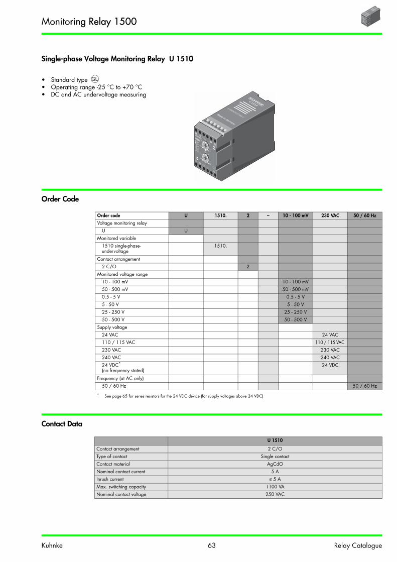
Kuhnke 63 Relay Catalogue
Single-phase Voltage Monitoring Relay U 15100
• Standard type • Operating range -25 °C to +70 °C• DC and AC undervoltage measuring
Order Code
Contact Data
Order code U 1510. 2 – 10 - 100 mV 230 VAC 50 / 60 Hz
Voltage monitoring relayU U
Monitored variable1510 single-phase-undervoltage
1510.
Contact arrangement2 C/O 2
Monitored voltage range10 - 100 mV 10 - 100 mV50 - 500 mV 50 - 500 mV0.5 - 5 V 0.5 - 5 V5 - 50 V 5 - 50 V25 - 250 V 25 - 250 V50 - 500 V 50 - 500 V
Supply voltage24 VAC 24 VAC110 / 115 VAC 110 / 115 VAC 230 VAC 230 VAC240 VAC 240 VAC24 VDC*
(no frequency stated)
* See page 65 for series resistors for the 24 VDC device (for supply voltages above 24 VDC)
24 VDC
Frequency (at AC only)50 / 60 Hz 50 / 60 Hz
U 1510
Contact arrangement 2 C/OType of contact Single contactContact material AgCdONominal contact current 5 AInrush current ≤ 5 AMax. switching capacity 1100 VA Nominal contact voltage 250 VAC
U
A111
21
B1B2
1214
2224
A2
0,5
0,7
0,3
0,9
0,1
1,00,50,8
0,6
0,9
0,5
0,99
U1510
U 1510U VDE0435,0110Gr.C
Monitoring Relay 1500ring Relay 1500U
A111
21
B1B2
1214
2224
A2
0,5
0,7
0,3
0,9
0,1
1,00,50,8
0,6
0,9
0,5
0,99
U1510
U 1510U VDE0435,0110Gr.C

Kuhnke 64 Relay Catalogue
Dimensions, Connection Diagram(s)
General Data
Auxiliary Circuituxiliary Circuit
U 1510
Display 1 green LED lights if the output relay is pulled up
Insulation group VDE 0110b/2.79 C250Test voltage
Auxiliary circuit - output circuit - monitoring circuit
2500 VAC
Vibration resistance 4 g at 25 - 100 Hz (in accordance with GL)Terminals Tension relief terminal with head screws metric M 2.6Terminal torque max. 0.6 NmTerminal capacity
solid conductor 2 x 1.5 mm2
flexible conductor with ferrule 2 x 1.5 mm2
Operating temperature -25 °C to +70 °CStorage temperature -25 °C to +85 °CProtection in accordance with DIN 40050 IP40 Housing
IP20 ScrewsIP10 Clamps
Mounting Rail in accordance with EN50022-35 x 7.5/15Screw mounting with mounting plate
Weight approx. 300 g
Nominal line voltages see order codeNominal line frequency 50 / 60 Hz if AC devices
Voltage ranges AC = ± 20 % at 100 % ED +50 % for 10 s 10 % EDDC = 24 VDC +25 %/-10 %
Rated power 2.0 VA cos ϕ ≈ 0.7
105.5 45
72
A2A1(+) (-)
A1 11 21 B1 B2
12 14 22 24
12
11 21
22 2414
A2
< U
B2B1
(-)~
-
Monitoring Relay 1500 500 U
A111
21
B1B2
1214
2224
A2
0,5
0,7
0,3
0,9
0,1
1,00,50,8
0,6
0,9
0,5
0,99
U1510
U 1510U VDE0435,0110Gr.C

Kuhnke 65 Relay Catalogue
Monitoring Circuit
Series Resistance for the 24 VDC DeviceVDC Device
U 1510
Pull-in voltage Uanadjustable acc. to the upper scale
Input resistancein kΩ
Continuous overloadin V
Overload duration10 s
10 - 100 mV 2 30 50 V50 - 500 mV 20 100 140 V0.5 - 5 V 82.5 200 280 V
5 - 50 V 511 500 700 V
25 - 250 V 1000 750 1000 V50 - 500 V 1000 750 1000 V
Adjustment error ≤ 4 %Drop-out voltage Uab Permanently adustable between 0.5 and 0.99 x Uan acc. to the lower scale.Temperature dependence ≤ 0.01 %/KVariance of switching points under identical conditions ≤ 0.5 %
Monitored value The arithmetic mean value is measured. The scales are adjusted to sinusoidal AC voltage. If just DC voltages without any harmonic contents are measured, the desired switching
point should be multiplied by 0.89 and the result set on the scale.
Supply voltage Uv in VDC 48 VDC 60 VDC 110 VDC 220 VDC
Series resistance Rv in Ω 470 750 1800 3900Power rating P of Rv in W 1.23 1.7 4.1 9.8Max. power P of Rv in W 1.92 2.7 6.4 15.4
Monitoring Relay 1500ay 1500U
A111
21
B1B2
1214
2224
A2
0,5
0,7
0,3
0,9
0,1
1,00,50,8
0,6
0,9
0,5
0,99
U1510
U 1510U VDE0435,0110Gr.C

Kuhnke 66 Relay Catalogue
Three-phase Voltage Monitoring Relay UD1515 / UD1525 / UD1535y UD1515 / UD1525 / UD1535
• Standard type • Operating range -25 °C to +70 °C• Monitoring of three-phase systems
Order Code
Contact Data
Order code UD 1525. 2 – 230 / 240 V 50 Hz
Three-phase voltageUD UD
Monitored variable1515 Three-phase undervoltage 1515.1525 Asymmetric three-phase angle 1525.1535 Three-phase sequence 1535.
Contact arrangement2 C/O 2
Measuring and supply voltage(Voltage: Phase - N / Phase - Phase)Voltage: Phase - N / Phase - Phase)
57 / 100 V 57 / 100 V110 / 190 V 110 / 190 V127 / 220 V 127 / 220 V230 / 400 V 230 / 400 V240 / 415 V 240 / 415 V290 / 500 V 290 / 500 V
Frequency50 / 60 Hz 50 / 60 Hz50 Hz (for UD 1525 only) 50 Hz
UD1515 / UD1525 / UD1535
Contact arrangement 2 C/OType of contact Single contactContact material AgCdONominal contact current 5 AInrush current ≤ 5 AMax. switching capacity 1100 VA Nominal contact voltage 250 VAC
U
A111
21
B1B2
1214
2224
A2
0,5
0,7
0,3
0,9
0,1
1,00,50,8
0,6
0,9
0,5
0,99
U1510
U 1510U VDE0435,0110Gr.C
Monitoring Relay 1500g Relay 1500U
A111
21
B1B2
1214
2224
A2
0,5
0,7
0,3
0,9
0,1
1,00,50,8
0,6
0,9
0,5
0,99
U1510
U 1510U VDE0435,0110Gr.C

Kuhnke 67 Relay Catalogue
Dimensions, Connection Diagram(s)mensions, Connection Diagram(s)
UD1515 / UD1525 UD1535
General Data
Auxiliary Circuit
• The supply input is internal connected to the monitoring input (L1 and L2).(L1 and L2).
UD1515 / UD1525 / UD1535
Display 1 green LED lights if the output relay is pulled upED lights if the output relay is pulled up
Insulation group VDE 0110b/2.79 C250Test voltage
Monitoring circuit - output circuit 2500 VAC
Vibration resistance 4 g at 25 - 100 Hz (in accordance with GL)Terminals Tension relief terminal with head screws metric M 2.6Terminal torque max. 0.6 NmTerminal capacity
solid conductor 2 x 1.5 mm2
flexible conductor with ferrule 2 x 1.5 mm2
Operating temperature -25 °C to +70 °CStorage temperature -25 °C to +85 °CProtection in accordance with DIN 40050 IP40 Housing
IP20 ScrewsIP10 Clamps
Mounting Rail in accordance with EN50022-35 x 7.5/15Screw mounting with mounting plate
Weight approx. 300 g
105.5 45
72
L2 L2N
L1 L3L1
L1 L2 L3 11 21
12 14 22 24
12
11 21
22 2414
N
< Us~
-
L2L1
L1 L2 L3 11 21
12 14 22 24
12
11 21
22 2414
N
< U
L1
L3 L2
~-
Monitoring Relay 1500onitoring Relay 1500U
A111
21
B1B2
1214
2224
A2
0,5
0,7
0,3
0,9
0,1
1,00,50,8
0,6
0,9
0,5
0,99
U1510
U 1510U VDE0435,0110Gr.C

Kuhnke 68 Relay Catalogue
Monitoring Circuit
UD1515 UD1525 UD1535
Nominal line voltages see order code Nominal line frequency 50 / 60 Hz 50 Hz ±0.5 %% 50 / 60 HzOverload rating 1.2 x UN continuous
1.5 x UN 10 s at 10 % ED
Rated power 2.4 VA cos ϕ ≈ 0.7
Monitored value Voltage reading Phase angle Phase sequence
Drop-out voltage
Adjustment error
Uab permanentlyadjustable between
0.7 and 1.0 x UN acc. to the upper scale
≤ 1%
AS permanently adjustable between 3° and 30° asymmetry of angles
≤ 2.5 %
Pull-in voltage
Adjustment error
Uan permanentlyadjustable between
1.02 and 1.2 x Uab acc. to the lower scale
≤ 2.5%
fixed setting at 1 % approx.
Variance of switching points at the three phases ≤ 1 %Temperature dependence ≤ 0.01 %/KK ≤ 0.01 %/KVariance of switching points under identical conditions
≤ 0.5 % ≤ 0.5 %
Monitoring Relay 1500500U
A111
21
B1B2
1214
2224
A2
0,5
0,7
0,3
0,9
0,1
1,00,50,8
0,6
0,9
0,5
0,99
U1510
U 1510U VDE0435,0110Gr.C

Kuhnke 699 Relay Catalogue
Single-phase Current Monitoring Relay I15400
• Standard type • Operating range -25 °C to +70 °C• Monitoring of undercurrent for DC and AC voltages
Order Code
Contact Data
Order code I 1540. 2 – 0.1 - 1 A 24 VAC 50 / 60 Hz
Current monitoring relayI I
Monitored variable1540 Single-phase - undercurrent
1540.
Contact arrangement2 C/O 2
Monitored current range
2 - 20 mA 2 - 20 mA10 - 100 mA 10 - 100 mA50 - 500 mA 50 - 500 mA0.1 - 1 A 0.1 - 1 A0.5 - 5 A 0.5 - 5 A1 - 10 A 1 - 10 A
Supply voltage24 VAC 24 VAC110 / 115 VAC 110 / 115 VAC 230 VAC 230 VAC240 VAC 240 VAC400 VAC 400 VAC24 VDC*
(no frequency stated)
* See page 71 for series resistors for the 24 VDC device (for supply voltages above 24 VDC)
24 VDC
Frequency50 / 60 Hz 50 / 60 Hz
I1540
Contact arrangement 2 C/OType of contact Single contactContact material AgCdONominal contact current 5 AInrush current ≤ 5 AMax. switching capacity 1100 VA Nominal contact voltage 250 VAC
U
A111
21
B1B2
1214
2224
A2
0,5
0,7
0,3
0,9
0,1
1,00,50,8
0,6
0,9
0,5
0,99
U1510
U 1510U VDE0435,0110Gr.C
Monitoring Relay 1500ay 1500U
A111
21
B1B2
1214
2224
A2
0,5
0,7
0,3
0,9
0,1
1,00,50,8
0,6
0,9
0,5
0,99
U1510
U 1510U VDE0435,0110Gr.C

Kuhnke 70 Relay Catalogue
Dimensions, Connection Diagram(s)
General Data
Auxiliary Circuituxiliary Circuit
I1540
Display 1 green LED lights if the output relay is pulled up
Insulation group VDE 0110b/2.7979 C250Test voltage
Auxiliary circuit - output circuit - monitoring circuit
2500 VAC
Vibration resistance 4 g at 25 - 100 Hz (in accordance with GL)Terminals Tension relief terminal with head screws metric M 2.6Terminal torque max. 0.6 NmTerminal capacity
solid conductor 2 x 1.5 mm2
flexible conductor with ferrule 2 x 1.5 mm2
Operating temperature -25 °C to +70 °CStorage temperature -25 °C to +85 °CProtection in accordance with DIN 40050DIN 40050 IP40 Housing
IP20 ScrewsIP10 Clamps
Mounting Rail in accordance with EN50022-35 x 7.5/15Screw mounting with mounting plate
Weight approx. 300 g
Nominal line voltages see order codeNominal line frequency 50 / 60 Hz if AC devices
Voltage ranges AC = ± 20 % at 100 % ED+50 % for 10 s 10 %ED
DC = 24 VDC +25 %/-10 %
Rated power 2.0 VA cos ϕ ≈ 0.7
105.5 45
72
A2A1(+) (-)
A1 11 21 B1 B2
12 14 22 24
12
11 21
22 2414
A2
< I
B2B1
(-)~
-
Monitoring Relay 1500g Relay 1500U
A111
21
B1B2
1214
2224
A2
0,5
0,7
0,3
0,9
0,1
1,00,50,8
0,6
0,9
0,5
0,99
U1510
U 1510U VDE0435,0110Gr.C

Kuhnke 71 Relay Catalogue
Monitoring Circuit
Series Resistance for the 24 VDC DeviceVDC Device
I1540
Pull-in current Ianadjustable acc. to the upper scaleble acc. to the upper scale
Input resistancein Ω
Continuous overloadin A
Overload duration 1 sin A
2 - 20 mA 3 0.5 0.6310 - 100 mA 1 1 1.2550 - 500 mA 0.25 2 2.5
0.1 - 1 A 0.11 3 3.7
0.5 - 5 A 0.01 10 12.251 - 10 A 0.005 15 15
Adjustment error ≤ 4 %Drop-out current Iab Permanently adjustable between 0.5 - 0.99 x Ian acc. to the lower scaleTemperature dependence ≤ 0.01 %/KVariance of switching points under identical conditions ≤ 0.5 %
Monitored value The arithmetic mean value is measured. The scales are adjusted to sinusoidal AC current. If just DC currents without any harmonic contents are measured, the desired switching
point should be multiplied by 0.89 and the result set on the scale.
Supply voltage Uv in VDC 48 VDC 60 VDC 110 VDC 220 VDC
Series resistance Rv in Ω 470 750 1800 3900Power rating P of Rv in WW 1.23 1.7 4.1 9.8Max. power P of Rv in W 1.92 2.7 6.4 15.4
Monitoring Relay 1500onitoring Relay 1500U
A111
21
B1B2
1214
2224
A2
0,5
0,7
0,3
0,9
0,1
1,00,50,8
0,6
0,9
0,5
0,99
U1510
U 1510U VDE0435,0110Gr.C

Kuhnke 72 Relay Catalogue
Frequency Monitoring Relay with Auxiliary Voltage F1570 h Auxiliary Voltage F1570
• Operating range -25 °C to +70 °C• Monitoring of underfrequency in AC current systemsquency in AC current systems
Order Codeder Code
Contact Data
Order code F 1570. 2 – 10 - 30 Hz 24 VAC 50 / 60 Hz
Frequency-monitoring relayF F
Monitored variable1570 underfrequency 1570.
Contact arrangement1 C/O / 1 N/O 2
Monitored frequency range
10 - 30 Hz 10 - 30 Hz20 - 50 Hz 20 - 50 Hz40 - 65 Hz 40 - 65 Hz50 - 100 Hz 50 - 100 Hz
Supply voltage24 VAC 24 VAC110 / 115 VAC 110 / 115 VAC 230 VAC 230 VAC240 VAC 240 VAC400 VAC 400 VAC24 VDCDC*
(no frequency stated)
* See page 74 for series resistors for the 24 VDC device (for supply voltages above 24 VDC)
24 VDC
Frequency50 / 60 Hz 50 / 60 Hz
F1570
Contact arrangement 1 C/O / 1 N/OType of contact Single contactContact material AgCdONominal contact current 5 AInrush current ≤ 5 AMax. switching capacity 1100 VA Nominal contact voltage 250 VAC
U
A111
21
B1B2
1214
2224
A2
0,5
0,7
0,3
0,9
0,1
1,00,50,8
0,6
0,9
0,5
0,99
U1510
U 1510U VDE0435,0110Gr.C
Monitoring Relay 1500500U
A111
21
B1B2
1214
2224
A2
0,5
0,7
0,3
0,9
0,1
1,00,50,8
0,6
0,9
0,5
0,99
U1510
U 1510U VDE0435,0110Gr.C

Kuhnke 73 Relay Catalogue
Dimensions, Connection Diagram(s)
General Data
Auxiliary Circuit
F1570
Display 1 green LED lights if the output relay is pulled up
Insulation group VDE 0110b/2.79 C250Test voltage
Auxiliary circuit - output circuit -monitoring circuit
2500 VAC
Vibration resistance 4 g at 25 - 100 Hz (in accordance with GL)GL)Terminals Tension relief terminal with head screws metric M 2.6Terminal torque max. 0.6 NmTerminal capacity
solid conductor 2 x 1.5 mm2
flexible conductor with ferrule 2 x 1.5 mm2
Operating temperature -25 °C to +70 °CStorage temperature -25 °C to +85 °CProtection in accordance with DIN 40050 IP40 Housing
IP20 ScrewsIP10 Clamps
Mounting Rail EN50022-35 x 7.5/15Screw mounting with mounting plate
Weight approx. 300 g
Nominal line voltages see order codeNominal line frequency 50 / 60 Hz if AC devices
Voltage ranges AC = ± 20 % at 100 % ED+50 % for 10 s 10 % ED
DC = 24 VDC +25 %/-10 %
Rated power 2.0 VA cos ϕ ≈ 0.7
105.5 45
72
A2A1(+) (-)
A1 11 21 B1 B2
12 14 24 X
12
11 21
2414
fB A2
< f
B2B1
(-)~
-
Monitoring Relay 1500ay 1500U
A111
21
B1B2
1214
2224
A2
0,5
0,7
0,3
0,9
0,1
1,00,50,8
0,6
0,9
0,5
0,99
U1510
U 1510U VDE0435,0110Gr.C

Kuhnke 74 Relay Catalogue
Monitoring Circuit
Series Resistance for the 24 VDC DeviceDC Device
F1570
Pull-in frequency fabadjustable acc. to the upper scale
Input resistancein MMΩ
Limiting frequency in Hz
10 - 30 Hz 1 120 20 - 50 Hz 1 120 40 - 65 Hz 1 120
50 - 100 Hz 1 120
Adjustment error ≤ 2.5 %Drop-out frequency fan Permanently adjustable between 1.01 and 1.1x fab acc. to the lower scaleTemperature dependence ≤ 0.02 %/KVariance of switching points under identical conditions
≤ 0.5 %
Monitored value (10 - 500 Veff) · Operation without bridge x-f: frequencies above the set pull-in value energise the output relay. The output relay is de-energised when the fre-quency falls below the set drop-out value.
· Operation with bridge x-f: the output relay pulls in if the measuring voltage is above 8 V. The output relay remains pulled in if the voltage is applied at a frequency above the set switching point. Other functions same as operation without bridge x-f.
Supply voltage Uv in VDC 48 VDC 60 VDC 110 VDC 220 VDC
Series resistance Rv in Ω 470 750 1800 3900900Power rating P of Rv in W 1.23 1.7 4.1 9.8Max. power P of Rv in W 1.92 2.7 6.4 15.4
Monitoring Relay 1500g Relay 1500U
A111
21
B1B2
1214
2224
A2
0,5
0,7
0,3
0,9
0,1
1,00,50,8
0,6
0,9
0,5
0,99
U1510
U 1510U VDE0435,0110Gr.C

Kuhnke 75 Relay Catalogue
PCB Relay 171
• Standard type /• Immunity to flux• 1 C/O 12/16 A. 2 C/O 8 A• Insulation group C250
Order Code
Contact Data
Order code 171 G 1 – 24 V DC
Type of relay 171Model
G For printed circuit GP For printed circuit (16 A) P
Contact arrangement1 C/O (Model G/P) 12 C/O (Model G) 2
Nominal operation coil voltage (see coil data)24 V 24 V
Coil current typeDC Direct current DCAC Alternating current AC
171G1 171G2 171P1
Contact arrangement 1 C/O 2 C/O 1 C/OType of contact Single contact Single contact Single contactContact material AgNi AgNi AgNi Nominal contact current 12 A 8 A 16 AInrush current ≤ 15 A ≤ 10 A ≤ 20 ANominal contact voltage 150 VDC / 250 VAC 150 VDC / 250 VAC 150 VDC / 400 VACMax. switching capacity (resistive) 192 W / 2000 VAW / 2000 VA 100 W / 1000 VA 240 W / 3000 VAMin. switching capacity 10 mA / 5 VDC 10 mA / 5 VDC 10 mA / 5 VDC
171-G1
24V DC
12A 250V AC
12A 250V AC
171 G1
171-G2
24V DC
10A 250V AC
8A 250V AC
171 G2
171-P1
24V AC
16A 250V AC
16A 250V AC
171 P1P1
High Performance PCB Relay 171CB Relay 171171-P1
24V AC
16A 250V AC
16A 250V AC

Kuhnke 76 Relay Catalogue
Dimensions, Connection Diagram(s)gram(s)
Hole diameter 1.3 mm Hole diameter 1.3 mm Hole diameter 1.3 mm
Top view Top view Top view
171 G1 171 G2 171 P1
General Data
Coil Data
171G1 171G2 171P1
Pull-in-time approx. 10 ms approx. 10 ms approx. 10 msDrop-out time approx. 8 ms approx. 8 ms approx. 8 ms Bounce time approx. 2 ms approx. 2 ms approx. 2 msMechanical service life > 20 x 106 switching cycles > 20 x 106 switching cycles > 20 x 106 switching cycles
> 5 x 10⁶ switching cycles AC > 5 x 10⁶ switching cycles AC > 5 x 10⁶ switching cycles ACTest voltage
Coil - contact (striking distance 8 mm)
5000 VAC 5000 VAC 5000 VAC
(C/O) - (C/O) 2500 VACContact - contact 1000 VAC 1000 VAC 1000 VAC
Insulation group VDE 0110b/2.79 C250 C250 C250, B380Ambient temperature -40 °C to +75 °C+75 °CVibration resistance (30 - 100 Hz) > 4 gWeight approx. 14 gOperating range Class 1 (0.8 – 1.1 UN)Pull-in
after coil excitationwith UN at TU 20 °C
Drop-out > 0.05 UN DC> 0.15 UN AC
Coil voltage DC
171G1/G2/P1Pull-in power approx. 0.2 W
Nom. operation coil power appr. 0.4 W
Coil voltageAC
171G1/G2/P1Nom. operation coil power appr. 50 Hz 0.7 VANom. operation coil power appr. 60 Hz 0.6 VA
Nominal voltage(V)
Nominal resistance (Ω)
Nominal current(mA)
Nominal voltage (V)
Nominal resist. (Ω)
Nominal current50 Hz (mA)
Nominal current60 Hz (mA)
12 360 33 24 350 32 2424 1440 17 115 8100 6.6 5.1
230 32500 3.3 2.5
2.5
3.53.516.7
12.70.
22.5
29
15.7
3.5
Viewed on relay from below
12.70.
2
2.5
29
15.7
3.5
Grid 2.5 x 2.5
Viewed on relay from below
12.70.
2
2.5
29
15.7
3.5
Grid 2.5 x 2.5
Viewed on relay from below
A1
A2 12
11
14
12 11 14
22 21 24
A1
A2 12 11 14
A1
A2
≥
High Performance PCB Relay 171gh Performance PCB Relay 171B Relay 171171-G1
24V DC
12A 250V AC
12A 250V AC

Kuhnke 77 Relay Catalogue
Electrical Service LifeElectrical Service Life AC90 % operating
resistive loadinductive loadcos ϕ = 0.4 ... 0.7
171 G1 171 G2 171 P1
Switching Capability DCBelow limiting characteristic: service life of contacts1 x 106 switching cycles (90 % operating)resistive load
Order Details for Accessories 171 der Details for Accessories 171
Relay 171 G1 171 G2/P1
Socket for Screw connection withquick-action fastening Z318.02 Safe separation Z319.02
printed circuit Z316.01 Z317.01Modules for socket Z318.02, Z319.02 Z318.51 Protection/luminous diode 24 VDC
Z318.52 Luminous diode 24 VAC/DCZ318.53 Protection diode DCZ318.54 24 VAC with varistorZ318.55 230 VAC with varistorZ318.58 110/230 VAC LED
Retaining clip for 171 Z438 for socket Z318.02 Z438 for socket Z319.02
10 2 5 2 5 2 5000100 10005
2
5
105
106
107
2
5
Serv
ice
life
of c
onta
ct
Switching capacity in VA10 2 5 2 5 2 5000100 1000
5
2
5
105
106
107
2
5
Serv
ice
life
of c
onta
ct
Switching capacity in VA10 2 5 2 5 2 5000100 1000
5
2
5
105
106
107
2
5
Serv
ice
life
of c
onta
ct
Switching capacity in VA
0 20 40 22060 80 100 120 140 160 180 2000.1
0.5
1
0.2
5
10
20
2
Switching voltage in V
Switc
hing
cur
rent
in A
High Performance PCB Relay 171Performance PCB Relay 171y 171171-G1
24V DC
12A 250V AC
12A 250V AC

Kuhnke 78 Relay Catalogue
PCB Relay 107
• Standard type /• Immunity to flux• 1 C/O 10/16 A, 2 C/O 7 A• Insulation group C250
107 G1 107 G2 107 P1
Order Code
Contact Data
Order code 107 G 1 – 24 V DC E
Type of relay 107Model
G For printed circuit GP For printed circuit (16 A) P
Contact arrangement1 C/O (Model G/P)O (Model G/P) 12 C/O (Model G) 2
Nominal operation coil voltage (see coil data)24 V 24 V
Coil current typeDC Direct current DCE High resistance coil E
ExtensionW Washable (on request) W
107G1 107G2 107P1
Contact arrangement 1 C/O 2 C/O 1 C/OType of contact Single contact Single contact Single contactContact material AgCdO AgCdO AgCdONominal contact current 10 A 7 A 16 AInrush current ≤ 10 A ≤ 5 A ≤ 16 ANominal contact voltage 150 VDC / 250 VAC 150 VDC / 250 VAC 150 VDC / 400 VACMax. switching capacity (resistive)witching capacity (resistive) 240 W / 2400 VA 120 W / 1200 VA 480 W / 4000 VAMin. switching capacity 100 mA / 5 VDC 100 mA / 5 VDC 100 mA / 5 VDC
107G1-12VDC
107G2-12VDC
107P1-12VDC
High Performance PCB Relay 107mance PCB Relay 10707107G1-12VDC

Kuhnke 79 Relay Catalogue
Dimensions, Connection Diagram(s)
Hole diameter 1.3 mm Hole diameter 1.3 mm Hole diameter 1.3 mm
Top view Top view Top view
107 G1 107 G2 107 P1
General Data
Coil Data
107 G1 107 G2 107 P1
Pull-in-time approx. 10 ms approx. 10 ms approx. 20 msDrop-out time approx. 5 ms approx. 5 ms approx. 10 ms Bounce time approx. 6 ms approx. 8 ms approx. 6 ms Mechanical service life > 20 x 106 switching cyclesTest voltage
Coil - contact (striking distance 8 mm)
4000 VAC 4000 VAC 4000 VAC
(C/O) - (C/O) 2500 VACContact - contact 1000 VAC 1000 VAC 1000 VAC
Insulation group VDE 0110b/2.7979 C250Ambient temperature -5 °C to +70 °C Vibration resistance (30 - 100 Hz) > 4 gWeight approx. 18 gOperating range Class 1 (0.8 – 1.1 UN)Pull-in
after coil excitationwith UN at TU 20 °C
Drop-out > 0.05 UN
Coil voltage High resistance 107 ... EPull-in power approx. 0.26 W
Nominal operation coil power approx. 0.52 W
Nominal voltage (V) Nominal resistance (Ω) Nominal current (mA)
6 68 8812 270 4424 1100 2248 4400 11
12.9
29.2
0.2
2.5
2.5 3.5 3.516.5
25.3
3.5
Viewed on relay from below
29.2
25.3
3.5
2.5
12.90.
2
Grid 2.5 x 2.5
Viewed on relay from below
29.2
25.3
3.5
2.5
12.90.
2
Grid 2.5 x 2.5
Viewed on relay from below
≥
High Performance PCB Relay 107mance PCB Relay 10707107G1-12VDC

Kuhnke 80 Relay Catalogue
Electrical Service Lifevice LifeElectrical Service Life AC90 % operating
resistive loadinductive loadcos ϕ = 0.4 ... 0.7
107 G1 107 G2 107 P1
Switching Capability DCBelow limiting characteristic: service life of contacts1 x 106 switching cycles (90 % operating)resistive load
107 G1 107 G2 107 P1
Order Details for Accessories 107
Relay 107 G1 107 G2/P1
Socket for Screw connection withquick-action fastening Z318.02 Safe separation Z319.02
printed circuit Z316.01 Z317.01Modules for socket Z318.02, Z319.02 Z318.51 Protection/luminous diode 24 VDC Modules as for 107 G1
Z318.52 Luminous diode 24 VAC/DCZ318.53 Protection diode DCZ318.54 24 VAC with varistorZ318.55 230 VAC with varistorZ318.58 110/230 VAC LED
Retaining clip Z421 for socket Z316.01 Z421 for socket Z317.01Retaining clip for 107 Z439 for socket Z318.02 Z439 for socket Z319.02
10 2 5 2 5 2 5000100 10005
2
5
105
106
107
2
5
Serv
ice
life
of c
onta
ct
Switching capacity in VA10 2 5 2 5 2 5000100 1000
5
2
5
105
106
107
2
5
Serv
ice
life
of c
onta
ct
Switching capacity in VA10 2 5 2 5 2 5000100 1000
5
2
5
105
106
107
2
5
Serv
ice
life
of c
onta
ct
Switching capacity in VA
0 20 40 60 80 100 120 140 160 220180 2000.1
0.5
1
0.2
5
10
20
2
Switching voltage in V
Switc
hing
cur
rent
in A
0 20 40 60 80 100 120 140 160 220180 2000.1
0.5
1
0.2
5
10
20
2
Switc
hing
cur
rent
in A
Switching voltage in V0 20 40 60 80 100 120 140 160 220180 200
0.1
0.5
1
0.2
5
10
20
2
Switc
hing
cur
rent
in A
Switching voltage in V
High Performance PCB Relay 107mance PCB Relay 10707107G1-12VDC

Kuhnke 81 Relay Catalogue
Socket Z316.01
Socket Z317.01
Socket Z318.02
Socket Z316.01
Socket design Safe separationTerminal capacity Soldered pinsMounting PCB mount
Nominal current 12 AInsulation group VDE 0110b/2.79 C250Weight approx. 3.5 gRetaining spring Z420 (171 only)
Socket Z317.01
Socket design Safe separationTerminal capacity Soldered pinsMounting PCB mount
Nominal current 12 AInsulation group VDE 0110b/2.79 C250Weight approx. 3.5 gRetaining spring Z420 (171 only), Z421 (107 G2/P1 only)
Socket Z318.02
Socket design Safe separation, logical, additional modules supportedTerminal capacity
solid conductor 2 x 2.5 mm2
flexible conductor with ferrule 2 x 1.5 mm2
Terminal designation in accordance with EN50005Mounting Rail EN50022-35 x 7.5/15
Screw mounting M3
Screw terminals Head screws metric M3Torque in accordance with DIN EN 60999 0.5 NmNominal current 12 AInsulation group VDE 0110b/2.79 C250, B380Electrical shock protection in accordance with VBG4 (professional association), VDE 0106 part 100Weight 22 gEject/retain clip Z438 for 171 G1
Z316.01
31
1310
Z317.01
31 13
10
NO
14
Z318.02
A1
A2 12
14
21
12A 300VAC
LR 26716
10A 300VAC
A2COIL
A1
11OONO
12
15.575
42
11 12
14
A2 A1
Accessories for Relays 171/107

Kuhnke 82 Relay Catalogue
Socket Z319.02
Socket Z315.02
Socket Z319.02
Socket design logical, additional modules supportedTerminal capacity
solid conductor 2 x 2.5 mm2
flexible conductor with ferrule 2 x 1.5 mm2
Terminal designation in accordance with EN50005Mounting Rail EN50022-35 x 7.5/15
Screw mounting M3
Screw terminals Head screws metric M3Torque in accordance with DIN EN 60999 0.5 NmNominal current 12 AInsulation group VDE 0110b/2.79 C250, B380Electrical shock protection in accordance with VBG4 (professional association), VDE 0106 part 100Weight 22 gEject/retain clip Z438 for 171, Z439 for 107 G/P1
Socket Z315.02
Socket design Safe separation, logical, additional modules supportedTerminal capacity
solid conductor 2 x 2.5 mm2
flexible conductor with ferrule 2 x 1.5 mm2
Terminal designation in accordance with EN50005Mounting Rail EN50022-35 x 7.5/15
Screw mounting M3
Screw terminals Head screws metric M3Torque in accordance with DIN EN 60999 0.5 NmNominal current 12 AInsulation group VDE 0110b/2.79 C250, B380Electrical shock protection in accordance with VBG4 (professional association), VDE 0106 part 100Weight 43 gEject/retain clip Z438 for 171, Z439 for 107 G/P1
11
Z319.02
A1
A2 12
14
21
A1
A2
2224
21
1214
11
12A 300VAC
LR 26716
10A 300VAC
24
NO
14
A2
COILA1
22
NO
12
15.575
42
14
11
24
21
A2 A1
22 12
Z315.02
12A 300V AC
MADE IN ITA
LY
15.5
61
75
21
24
A2 A1
11
22 12
14
Accessories for Relays 171/107

Kuhnke 83 Relay Catalogue
Modules for Socket Z318.02, Z319.02, and Z315.02
Z318.51 Z318.52 Z318.53 Protection / luminous diode for 6 - 24 VDC LED for 6 - 24 VAC / DC Protection diode
Z318.54 Z318.55 Z318.58 Varistor for 24 VAC Varistor for 230 VAC LED for 110 / 230 VAC
Eject/retain Clip Z438 (for Z318.02, Z319.02, and Z315.02 with relay 171)
Eject/retain Clip Z439 (for Z318.02, Z319.02, and Z315.02 with relay 107 G2 and 107 P1)
A1+
-A2
Z318.516/24 V DC
8 12
23
A1 +- A2 A1 +- A2 ~ ~
A1 +- A2
A1A2
U
A1A2
U
A1A2
23 15
38.5
23
47.5
15
Accessories for Relays 171/107

Kuhnke 84 Relay Catalogue
PCB Relay 173
• Standard type /• Immunity to flux• 1 C/O 5 A• Insulation group C250
Order Code
Contact Data
Dimensions, Connection Diagram(s)sions, Connection Diagram(s)
Hole diameter 1.2 mm Top view
Order code 173 G 1 – 24 V DC
Type of relay 173Model
G For printed circuit GContact arrangement
1 C/O 1Nominal operation coil voltage (see coil data)
24 V 24 VCoil current type
DC Direct current DC
173G1
Contact arrangement 1 C/OType of contact Single contactContact material AgNi, gold-plated Nominal contact current 5 AInrush current ≤ 5 ANominal contact voltage 150 VDC / 250 VACMax. switching capacity (resistive) 120 W / 960 VAMin. switching capacity 10 mA / 5 VDC
173G1-24VDC
16.4
21.4
14.8
4
1.99
1.8 Grid 2.54 x 2.54
Viewed on relay from belowbelow
High Performance PCB Relay 173CB Relay 173173G1-24VDC

Kuhnke 85 Relay Catalogue
General Data
Coil Data
Electrical Service LifeElectrical Service Life AC Switching Capability DC90 % operation Below limiting characteristics: service life of contacts: service life of contacts
resistive load 1 x 10⁶ switching cycles (90 % operation)inductive load resistive loadcos ϕ = 0.4 ... 0.7
173G1
Pull-in-time approx. 7 msDrop-out time approx. 4 ms Bounce time approx. 2 ms Mechanical service life > 20 x 106 switching cyclesTest voltage
Coil - contact 2000 VACContact - contact 750 VAC
Insulation group VDE 0110b/2.79 C250Ambient temperature -30 °C to +70 °CVibration resistance (30 - 100 Hz) > 10 g Weight approx. 8 g Operating range Class 1 (0.8 – 1.1 UUN)Pull-in
after coil excitationwith UN at TU 20 °C
Drop-out > 0.05 UN
Coil voltage DC
Nominal operation coil power approx. 0.45 WPull-in power approx. 0.22 W
Nominal voltage (V) Nominal resistance (Ω) Nominal current (mA)
5 56 8912 320 3824 1280 19
10 2 5 2 5 2 5000100 10005
2
5
105
106
107
2
5
Serv
ice
life
of c
onta
ct
Switching capacity in VA0 20 40 60 80 100 120 140 160 180 200 220
0.1
0.5
1
0.2
5
8
2
Switc
hing
cur
rent
in A
Switching voltage in V
High Performance PCB Relay 173CB Relay 173173G1-24VDC

Kuhnke 86 Relay Catalogue
PCB Relay 174B Relay 174
• Standard type /• Washable• 1 C/O 10 A/ 400 VACC/O 10 A/ 400 VAC• Insulation group C250, B380• Overall height 12.5 mm
Order Code
Contact Data
Dimensions, Connection Diagram(s)mensions, Connection Diagram(s)
Hole diameter contacts 1.5 mm Top viewHole diameter coil 1.3 mm
Order code 174 G 1 – 24 V DC
Type of relay 174Model
G For printed circuit GContact arrangement
1 C/O 1Nominal operation coil voltage (see coil data)
24 V 24 VCoil current type
DC Direct current DC
174G1
Contact arrangement 1 C/OType of contact Single contactContact material AgCdONominal contact current 8 AInrush current ≤ 15 ANominal contact voltage 150 VDC / 400 VACMax. switching capacity (resistive) 192 W / 2000 VAMin. switching capacity 10 mA / 5 VDC
174G1-24VDC
1.19
2.54
2.1 3.2 3.218.9
10
29
12.5
3.3
Viewed on relay from below
High Performance PCB Relay 174CB Relay 174174G1-24VDC

Kuhnke 87 Relay Catalogue
General Data
Coil Data
Electrical Service LifeElectrical Service Life AC Switching Capability DC90 % operation% operation Below limiting characteristics: service life of contacts
resistive load 1 x 10⁶ switching cycles (90 % operation)inductive load resistive loadcos ϕ = 0.4 ... 0.7
174G1
Pull-in-time approx. 10 msDrop-out time approx. 5 ms Bounce time approx. 2 ms Mechanical service life > 20 x 106 switching cyclesTest voltage
Coil - contact 5000 VACContact - contact 1000 VAC
Insulation group VDE 0110b/2.79 C250, B380Ambient temperature -40 °C to +70 °C°C to +70 °CVibration resistance (30 - 100 Hz) > 4 g Weight approx. 8 gOperating range Class 1 (0.8 – 1.1 UN)Pull-in
after coil excitationwith UN at TU 20 °C
Drop-out > 0.05 UN
Coil voltage DC
Nominal operation coil power approx. 0.25 WPull-in power approx. 0.12 W
Nominal voltage (V) Nominal resistance (Ω) Nominal current (mA)
6 164 3712 620 1924 2350 1048 9600 5
10 2 5 2 5 2 5000100 10005
2
5
105
106
107
2
5
Serv
ice
life
of c
onta
ct
Switching capacity in VA0 20 40 60 80 100 120 140 160 180 200 220
0.5
1
0.2
5
10
2
0.1
Switc
hing
cur
rent
in A
Switching voltage in V
High Performance PCB Relay 174CB Relay 174174G1-24VDC

Kuhnke 88 Relay Catalogue
PCB Relay 175
• Standard type /• Washable• 1 N/O 5 A• Insulation group C250
Order Code
Contact Data
Dimensions, Connection Diagram(s)
Hole diameter 1.3 mm Top view
Order code 175 G 100 – 24 V DC
Type of relay 175Model
G For printed circuit GContact arrangement
100 1 N/O 100Nominal operation coil voltage (see coil data)
24 V 24 VCoil current type
DC Direct current DC
175G100
Contact arrangement 1 N/OType of contact Single contactContact material AgCdONominal contact current 5 AInrush current ≤ 5 ANominal contact voltage 30 VDC / 250 VACMax. switching capacity (resistive) 150 W / 1250 VAMin. switching capacity 100 mA / 5 VDC
175G100-24VDC
9.8
21
12.8
3.3
1.09
1.6 Grid 2.54 x 2.54
Viewed on relay from below
High Performance PCB Relay 175175G100-24VDC

Kuhnke 89 Relay Catalogue
General Data
Coil Data
Electrical Service LifeElectrical Service Life AC Switching Capability DC90 % operation Below limiting characteristics: service life of contactsmiting characteristics: service life of contacts
resistive load 1 x 10⁶ switching cycles (90 % operation)inductive load resistive loadcos ϕ = 0.4 ... 0.7
175G100
Pull-in-time approx. 6 ms Drop-out time approx. 3 ms Bounce time approx. 1 ms Mechanical service life > 20 x 106 switching cyclesTest voltage
Coil - contact 4000 VACInsulation group VDE 0110b/2.79 C250Ambient temperature -40 °C to +85 °CVibration resistance (30 - 100 Hz) > 10 gWeight approx. 5 g Operating range Class 1 (0.8 – 1.1 UN)Pull-in
after coil excitationwith UN at TU 20 °C
Drop-out > 0.05 UN
Coil voltage DC
Nominal operation coil power approx. 0.20 WPull-in power approx. 0.10 W
Nominal voltage (V) Nominal resistance (Ω) Nominal current (mA)
5 125 4012 720 1724 2880 8
10 2 5 2 5 2 5000100 10005
2
5
105
106
107
2
5
Serv
ice
life
of c
onta
ct
Switching capacity in VA0 20 40 60 80 100 120 140 160 180 200 220
0.1
0.5
1
0.2
5
8
2
Switc
hing
cur
rent
in A
Switching voltage in V
High Performance PCB Relay 175CB Relay 175175G100-24VDC

Kuhnke 900 Relay Catalogue
PCB Relay 176 Relay 176
• Standard type /• Washable• 1 C/O 5 A• Insulation group C250
Order Code
Contact Data
Dimensions, Connection Diagram(s)(s)
Hole diameter contacts 1.2 mm Top view Hole diameter coil 1.0 mm
Order code 176 G 1 – 24 V DC
Type of relay 1766Model
G For printed circuit GContact arrangement
1 C/O 1Nominal operation coil voltage (see coil data)
24 V 24 VCoil current type
DC Direct current DC
176G1
Contact arrangement 1 C/OType of contact Single contactContact material AgCdONominal contact current 5 AInrush current ≤ 5 ANominal contact voltage 150 VDC / 250 VACMax. switching capacity (resistive) 120 W / 1250 VAMin. switching capacity 100 mA / 5 VDC
176G1-6VDC
10.5
20.5
20.5
3.5
1.4
1.4 Grid 2.54 x 2.54
Viewed on relay from below
High Performance PCB Relay 176CB Relay 176176G1-6VDC

Kuhnke 91 Relay Catalogue
General Data
Coil Data
Electrical Service LifeElectrical Service Life AC Switching Capability DC90 % operation Below limiting characteristics: service life of contactsvice life of contacts
resistive load 1 x 10⁶ switching cycles (90 % operation)inductive load resistive loadcos ϕ = 0.4 ... 0.7
176G1
Pull-in-time approx. 10 msDrop-out time approx. 5 ms Bounce time approx. 8 ms Mechanical service life > 10 x 106 switching cyclesTest voltage
Coil - contact 2000 VACContact - contact 750 VAC
Insulation group VDE 0110b/2.79 C250Ambient temperature -40 °C to +85°CVibration resistance (30 - 100 Hz) > 10 g Weight approx. 8 g Operating range Class 1 (0.8 – 1.1 UN)Pull-in
after coil excitationwith UN at TU 20 °C
Drop-out > 0.05 UN
Coil voltage DC
Nominal operation coil power approx. 0.36 W Pull-in power approx. 0.18 W
Nominal voltage (V) Nominal resistance (Ω) Nominal current (mA)
6 100 6012 400 3024 1600 15
10 2 5 2 5 2 5000100 10005
2
5
105
106
107
2
5
Serv
ice
life
of c
onta
ct
Switching capacity in VA0 20 40 60 80 100 120 140 160 180 200 220
0.1
0.5
1
0.2
5
8
2
Switc
hing
cur
rent
in A
Switching voltage in V
High Performance PCB Relay 176CB Relay 176176G1-6VDC

Kuhnke 92 Relay Catalogue
Dual In-Line Relays 178
• Standard type /• Washable• Small overall height• For switching small signals
Order Code
Contact Data
Dimensions, Connection Diagram(s)mensions, Connection Diagram(s)
Viewed on relayfrom below
Hole diameter 0.8 mm Top view
Order code 178 G 2 – 24 V DC
Type of relay 178Model
G For printed circuit GContact arrangement
2 C/O 2Nominal operation coil voltage (see coil data)
24 V 24 VCoil current type
DC Direct current DC
178G2
Contact arrangement 2 C/OType of contact Twin contactContact material Hard silver, gold-plated Nominal contact current 2 AInrush current ≤ 2 ANominal contact voltage 110 VDC / 125 VACMax. switching capacity (resistive) 30 W / 62.5 VAMin. switching capacity 100 µA / 10 mV DCµA / 10 mV DC
178G2-24VDC
9
14
53.
3
0.69
1.92 Grid 2.54 x 2.54
–+
Dual In-Line Relays 1788178G2-24VDC

Kuhnke 93 Relay Catalogue
General Data
Coil Data
Electrical Service Life(resistive load), 90 % operating
178G2
Pull-in-time approx. 5 msDrop-out time approx. 4 ms Bounce time approx. 1 ms Mechanical service life > 20 x 106 switching cyclesTest voltage
Coil - contact 1000 VAC(C/O) - (C/O) 1000 VACContact - contact 1000 VAC
Capacities Contact - contact approx. 0.5 pFCoil - contact approx. 1 pF
Insulation group VDE 0110b/2.79 C30, B125Ambient temperature -40 °C to +85 °C+85 °CVibration resistance (30 - 100 Hz) > 10 g Weight approx. 1.5 gOperating range Class 1 (0.8 – 1.1 UN)Pull-in
after coil excitationwith UN at TU 20 °C
Drop-out > 0.05 UN
Coil voltage DC
Nominal operation coil power approx. 0.14 - 0.2 WPull-in power approx. 0.07 - 0.1 W
Nominal voltage (V) Nominal resistance (Ω) Nominal current (mA)
5 178 2812 1028 1224 2880 8
178G2
Switching voltageSwitching currentElectrical service life
30 VDC1 A
0.5 x 10⁶ switching cycles
125 VAC0.5 A
0.2 x 10⁶ switching cycles
Dual In-Line Relays 17878178G2-24VDC

Kuhnke 94 Relay Catalogue
Dual In-Line Relays RERelays RE
• Standard type /• Washable• High resistance version • For switching small signals
Order Code
Contact Data
Order code R E 2 L – 24 V DC
Type of relay RModel
E For printed circuit, high resistance coil EContact arrangementment
2 C/O 2Type of contact
L Twin contacts LNominal operation coil voltage (see coil data)
24 V 24 VCoil current type
DC Direct current DC
RE monostable, poled
Contact arrangement 2 C/OType of contact Twin contactContact material Hard silver, gold-platedNominal contact current 2 AInrush current ≤ 2 ANominal contact voltage 120 VDC / ACMax. switching capacity (resistive) 24 W / 60 VAMin. switching capacity 100 µA / 10 mVDC
RE 2L-24VDC
Dual In-Line Relays REERE 2L-24VDC

Kuhnke 95 Relay Catalogue
Dimensions, Connection Diagram(s)
Hole diameter 0.8 mm
Top view
General Data
RE monostable, poled
Pull-in-time approx. 6 ms Drop-out time approx. 4 ms Bounce time approx. 1 ms Mechanical service life > 20 x 106 switching cycles Test voltage
Coil - contact 1500 VAC(C/O) - (C/O) 1500 VACContact - contact 1000 VAC
CapacitiesCoil - contact 3 pF(C/O) - (C/O) 1.5 pFContact - contact 2.5 pF
Insulation group VDE 0110b/2.79b/2.79 A125Ambient temperature -40 °C to +70 °CVibration resistance (30 - 100 Hz) > 10 gWeight approx. 3.7 g Operating range Class 1 (0.8 – 1.1 UN)Pull-in
after coil excitationwith UN at TU 20 °C
Drop-out > 0.05 UN
1020
9.9
3.3
1.19
1.14 Grid 2.54 x 2.54
Viewed on relay from below
–+
Dual In-Line Relays RERE 2L-24VDC

Kuhnke 96 Relay Catalogue
Coil Data
Electrical Service Life(resistive load), 90 % operating
Coil voltage DC
RE monostable, poledPull-in power approx. 0.1 W
Nominal operation coil power approx. 0.2 W
Nominal voltage(V)
Nominal resistance(Ω)
Nominal current(mA)
5 167 3012 960 12.524 2880 8.348 11520 4.2
RE monostable, poled
Switching voltageSwitching currentElectrical service life
24 VDC1 A
0.5 x 10⁶ switching cycles
Switching voltageSwitching currentElectrical service life
120 VAC0.5 A
0.2 x 10⁶ switching cycles
Dual In-Line Relays RERE 2L-24VDC

Kuhnke 97 Relay Catalogue
Table of Contents
1. Definitions taken from relay regulations ............................................................ 991.1 Definitions .................................................................................................... 991.1.1 Coil terms..................................................................................................... 991.1.2 Terms relating to time..................................................................................... 991.1.3 Contact terms................................................................................................ 991.2 Reference conditions ...................................................................................... 991.3 Input values ................................................................................................ 1001.3.1 Operating range ......................................................................................... 1001.3.2 Release ...................................................................................................... 1001.4 Creepage and clearance distances................................................................ 1001.4.1 Insulation groups ......................................................................................... 1001.4.2 Insulation coordination ................................................................................. 1011.4.2.1 Surge voltage test ........................................................................................ 1011.4.2.2 Netfrequency alternating voltage test ............................................................. 1011.55 Usage categories ........................................................................................ 1021.6 Screw torque .............................................................................................. 103
2. Regulations for relay applications .................................................................. 1032.1 Manufacturer's certificate ............................................................................. 1032.2 Contact protection ....................................................................................... 1032.3 Safe separation........................................................................................... 1032.4 Protection by casings ................................................................................... 1042.5 Plant safety ................................................................................................. 1042.6 Line voltage harmonisationvoltage harmonisation ........................................................................... 104
3. Selection and application of relays ................................................................ 1053.1 Extended operating conditions ...................................................................... 1053.1.1 Low temperature.......................................................................................... 1053.1.2 High temperature......................................................................................... 1053.1.3 Humidity..................................................................................................... 1053.2 Climate application classes........................................................................... 1053.3 Service life / reliability................................................................................. 10663.3.1 Mechanical service life................................................................................. 1063.3.2 Electrical service life..................................................................................... 1063.3.2.1 Inductive loads ............................................................................................ 1083.3.2.2 Lamp loads ................................................................................................. 1083.3.2.3 Fluorescent lamps ........................................................................................ 1083.3.2.4 Capacitors.................................................................................................. 1083.4 Protective circuits ......................................................................................... 1093.4.1 Protective DC circuit..................................................................................... 1093.4.2 Protective AC and DC circuitsAC and DC circuits ....................................................................... 1093.4.3 RC element circuit............................................................................................... 1103.4.4 Suppressor diode ........................................................................................ 1103.4.5 Protective circuits - summary.......................................................................... 1113.5 Contact types and materials.......................................................................... 1113.5.1 Contact types.............................................................................................. 1113.5.2. Contact materials ........................................................................................ 1123.5.2.1 Hard silver.................................................................................................. 112
Technical Notes

Kuhnke 98 Relay Catalogue
3.5.2.2 Silver cadmium oxide ................................................................................... 1123.5.2.3 Silver palladium........................................................................................... 1123.5.2.4 Silver tin oxide ............................................................................................ 1123.5.2.5 Silver nickel................................................................................................. 1123.5.2.6 Gold plating 10 µm ..................................................................................... 1133.5.2.7 Gold plating 3 µm ....................................................................................... 1133.5.2.8 Tungsten ..................................................................................................... 1133.5.3 Contact resistance........................................................................................ 1133.5.3.1 Increased reliability of contact making by ....................................................... 1143.5.3.2 Measuring conditions ................................................................................... 1143.5.3.3 Evaluation of contact resistances.................................................................... 1143.5.4 Selective list of contact loads ......................................................................... 1153.6 Relay types in terms of housing...................................................................... 1153.7 Instructions for working up of PCB relays ........................................................ 1163.7.1 Soldering instructions for sockets.................................................................... 1163.7.2 Production of PCBs for relays......................................................................... 1163.7.3 Fixing relays on the boards ........................................................................... 1163.7.4 Fluxing PCBs and relays ............................................................................... 1163.7.5 Soldering of PCB relays ................................................................................ 1163.7.6 Cleaning of relays after soldering .................................................................. 1173.8 Relay installation positions ............................................................................ 1173.8.1 Armature positions ....................................................................................... 1173.8.22 Orientation of contacts ................................................................................. 117
4. Relays according to German and international regulations................................ 1184.1 Scope of coverage of VDE ............................................................................ 1184.2 Declaration of conformity.............................................................................. 1184.3 CE mark ..................................................................................................... 1184.4 Licences...................................................................................................... 119
Technical Notes

Kuhnke 99 Relay Catalogue
1. Definitions taken from relay regulations1.1 Definitions1.1.1 Coil terms
Nominal coil voltage is the voltage for which the coil is designed and rated and to which the other characteristic values are related.Nominal coil current of units with coil winding is the current occurring at nominal voltage and a winding temperature of 20 °C.Nomincal coil resistance is the coil's DC resistance at 20 °C.Nominal coil power rating is the power consumption at nominal voltage and nominal frequency, if applicable, i.e. the product of nominal voltage and nominal current.Threshold current (voltage) is the minimum current (voltage) at which the relay positively pulls in.Pull-in power is the average power consumption of a relay at threshold voltage (winding temperature 20 °C).Transient current (pick-up current) is the current flowing through an AC winding at nominal voltage when the armature is held in the home position.Release current is the current at which the relay armature is released.Maximum permissible voltage is the voltage at which, at the max. ambient temperature, the max. permissible temperature is not exceeded.
1.1.2 Terms relating to timeResponse time is the time between applying power to the coil and reaching the operating position (measured without bounce time).Release time is the time between disconnecting power and leaving the operating position (measured without bounce time).Bounce time is the time between the first and the complete closing (or opening) of a contact during closing (or opening) processes.
1.1.33 Contact termsNominal contact voltage is the voltage for which a contact element is rated to switch under stipulated conditions.Switching voltage is the voltage applied to the open contact; it must not exceed the nominal contact voltage.Nominal contact current is the maximum current that a contact can carry continuously under stipulated conditions. DIN EN 61810-1/VDE 0435 Part 201 demands that at least half of a 1810-1/VDE 0435 Part 201 demands that at least half of a relay's N/O contacts is to be capable of carrying the nominal current.pable of carrying the nominal current.Switching current is the current actually flowing through the closed contact; it can considerably exceed the nominal contact current for short periods.Switching capacity is the product of switching voltage and switching current.
1.2 Reference conditions in compliance with DIN EN 61810-1/VDE 0435 Part 20161810-1/VDE 0435 Part 201The standard operating ranges of influencing variables refer to the recommended relay operating ranges.Influencing variable Standard operating rangeAmbient temperature -5 to +55 °C Air pressure 70 to 110 kPaRelative humidity see section 3.2, neither condensation nor ice must 3.2, neither condensation nor ice must
occur inside the relay housing.Foreign magnetic induction 15 x 10-4 T in any directionPosition 5° in any direction away from the reference positionFrequency Reference value +10 %/-6 %6 %DC ripple ≤ 12 %DC portion of AC max. 5 % of peak voltage Shock and vibration according to manufacturer’s dataIndustrial exhausts and other influences in process by IEC
Technical Notes

Kuhnke 100 Relay Catalogue
1.3 Input values in compliance with DIN EN 61810-1/VDE 0435 Part 201ut values in compliance with DIN EN 61810-1/VDE 0435 Part 2010-1/VDE 0435 Part 2011.3.1 Operating range
Class 1 80 to 110 % of nominal voltage0 to 110 % of nominal voltageClass 2 85 to 110 % of nominal voltage
1.3.2 ReleaseDC relay > 5 % of nominal voltage
> 10 % of the nominal voltage under nominal conditionsAC relay > 15 % of nominal voltage
1.4 Creepage and clearance distances in compliance with DIN EN 61810-1/VDE 0435 Part 201nd clearance distances in compliance with DIN EN 61810-1/VDE 0435 Part 2010-1/VDE 0435 Part 201Where creepage and clearance distances are concerned, this European standard refers to DIN EN 61810-5/VDE 0435 Part 140. Creepage and clearance distance ratings of electrical relays 61810-5/VDE 0435 Part 140. Creepage and clearance distance ratings of electrical relays are currently defined in accordance with VDE 0110 b/ 2.79 as yet.2.79 as yet.
1.4.14.1 Insulation groups in acc. with VDE 0110 b/ 2.79VDE 0110 b/ 2.79 stipulates the minimum insulation distances for operating equipment. Accor-ding to its use and operating conditions, the equipment is classified by one of the insulation groups below:Insulation group Ao includes low-output equipment which is installed in air-conditioned or cle-
an, dry rooms, or is protected by suitable means; minor temperature rise in the case of short circuit.
Insulation group A includes equipment which is installed in air-conditioned or clean, dry rooms, or is protected by suitable means.
Insulation group BB includes equipment in domestic or commercial rooms, precision enginee-ring workshops, laboratories, test bays, or medical care locations.
Insulation group C includes equipment primarily for use in industrial, commercial and agricul-tural environments, unheated storerooms, workshops, boiler houses, or in conjunction with machine tools.
Insulation group D includes equipment for use in vehicles which are exposed to the effects of conducting brake dust and moisture (condensation, snow) without being enclosed.
The insulation group is to be chosen according to the application. Apart from the insulation group, the operating voltage is to be taken into account.
Technical Notes

Kuhnke 101 Relay Catalogue
1.4.2 Insulation coordination in acc. with DIN EN 61810-5/VDE 0435, Part 140810-5/VDE 0435, Part 140The standard defines the requirements to insulation coordination for the electromechanical swit-ching relays. For the purpose of insulation coordination, the devices due to IEC 60664-1 are clas-0664-1 are clas-sified by the following groups:Overvoltage category I covers devices that connect to fixed electrical installations
in buildings; measures for the limitation of transient surges are to be provided.
Overvoltage category II covers devices that connect to fixed electrical installations in buildings (e.g. household appliances, portable tools and similar loads).
Overvoltage category III covers devices that are components of fixed installations (e.g. distributor boards, power switches, distributors) and devices that can be permanently connected to a fixed instal-lation at any time (e.g. devices for industrial applications, stationary motors).
Overvoltage category IV covers devices that are intended for use at or near the fee-ding point of electrical installations in buildings, looking from the main junction box towards the line (e.g. electricity meters, overload switches).
Relays for industrial applications fall under Overvoltage category III. The ’Pollution degree’ defines the contamination, which may reduce the stability or the surface resistance of the insulation.Pollution degree 1 covers dry and non-conductive contamination without any
influence.Pollution degree 2 covers non-conductive contamination which, due to conden-
sation, may become conductive at times.Pollution degree 3 covers conductive contamination or dry, non-conductive
contamination which will become conductive because con-densation is expected.
Pollution degree 4 covers contamination that is always conductive due to con-ductive dust, rain or snow.
In conjunction with the operating voltage and the relay’s overvoltage category results the rated impulse withstand voltage.
1.4.2.1 Surge voltage test in acc. with IEC 60664-160664-1Test voltage Impulse withstand voltage due to DIN EN 61810-5/VDE 0-5/VDE
0435 Part 140 curve shape 1.2/50 µs
1.4.2.2 Netfrequency alternating voltage test in acc. with IEC 60664-1Test voltage AC
2 x UN + 1000 V for 1 min in
Technical Notes

Kuhnke 102 Relay Catalogue
1.5 Usage categories in acc. with DIN EN 60947-4-1/VDE 0660 Part 102 ories in acc. with DIN EN 60947-4-1/VDE 0660 Part 102 /VDE 0660 Part 102 and DIN EN 60947-5-1/VDE 0660 Part 2005-1/VDE 0660 Part 200
The usage categories listed in DIN EN 60947-4-1/VDE 0660 Part 102 in conjunction with the nominal operating current and the nominal voltage mark the intended use and the load on perating current and the nominal voltage mark the intended use and the load on contactors and motor switches (up to 1000 VAC or 1500 VDC).
The usage categories listed in DIN EN 60947-5-1/VDE 0660 Part 200 apply to control devices 47-5-1/VDE 0660 Part 200 apply to control devices and switching elements for controlling, signal output, locking etc. of switching gear and switching systems (up to 1000 VAC or 600 VDC).AC or 600 VDC).
The diagram below illustrates the making and breaking currents according to the test conditions of the usage categories.
Ic = making-, breaking currentle = rated operating currentIc/Ie = 1 for the usage categoriesnot shown in the diagram
Type of current Usage category Typical application
Alternating current AC - 1AC - 2 AC - 3AC - 4
AC - 5aAC - 5bAC - 6aAC - 6bAC - 7a
AC - 7bAC - 8a
AC - 8b
non-inductive or low-induction loads, resistance ovensslip ring motors: start, stopsquirrel-cage motors: start, stop during operationsquirrel-cage motors: start, reverse current braking, reversing, inchingcontrol of gas discharge lampscontrol of filament bulbscontrol of transformerscontrol of capacitor batterieslow-induction loads of household appliances and similar applicationsmotor loads for household applicancescontrol of hermetically enclosed cooling compressor motors with manual reset of overload triggerssame as AC-8a, but with automatic reset
Direct current DC - 1DC - 3
DC - 5
DC - 6
non-inductive or low-inductance loads, resistance ovensshunt wound motors: start, reverse current braking, reversing, inching, resistance brakingseries wound motors: start, reverse current braking, reversing, inching, resistance brakingcontrol of filament bulbs
Type of current Usage category Typical application
Alternating current AC - 12
AC - 13AC - 14AC - 15
control of resistive and semiconductor loads in the input circuits of opto-couplerscontrol of semiconductor loads with transformer separationcontrol of small electromagnetic loads (max. 72 VA)control of electromagnetic loads (above 72 VA)
Direct current DC - 12
DC - 13DC - 14
control of resistive and semiconductor loads in the input circuits of opto-couplerscontrol of solenoidscontrol of electromagnetic loads with economy resistors in the circuit
1
0
2
3
4
5
6
7
8
9
10
A C
2
A C
3
A C
4
A C
5 a
A C
8 b
A C
1 3
A C
1 4
A C
1 5
D C
3
D C
5
D C
1 4
Usage categories
Ic/I
e
Technical Notes

Kuhnke 103 Relay Catalogue
1.6 Screw torque in acc. with DIN EN 60999-1/VDE 0609 Part 1ue in acc. with DIN EN 60999-1/VDE 0609 Part 1The standard applies to the terminal points of screw-type terminals for the connection of single copper wires (max. diameter = 240 mm240 mm2) or several copper wires of the same diameter (max. 70 mm2 per terminal).The largest nominal diameter defined for the terminal point is used for the torque test. The wires are to be attached to and detached from the terminal point 5 times, using the test torques accor-ding to the table below. After the test, the terminal points must show no changes that would influ-ence their use.
2. Regulations for relay applications2.1 Manufacturer's certificate (installer's certificate) in acc. with VBG 4 §5, para. 4VBG 4 §5, para. 4
VBG4, a regulation issued by the employers' liability insurance association, describes the protec-G4, a regulation issued by the employers' liability insurance association, describes the protec-tive means of plants against accidental contact with electrically conductive parts. This regulation is a statutory obligation for plant operators. Responsibility can be transferred to the installer of the plant. Prior to its first start-up, the plant is to be checked and approved of by a qualified engineer who is to assess all of the protective means against accidental contact. The efficiency of protection can be assured by the installer of the overall system only. The certificate demanded by VBG4 §5, para. 4 cannot be provided by component suppliers because the supplier has no influence on the installation and application conditions.
2.2 Contact protection in acc. with DIN VDE 0106 Part 100DIN VDE 0106 Part 100VDE 0106 Part 100 is the basis for the design of electrical equipment for nominal voltages up to DE 0106 Part 100 is the basis for the design of electrical equipment for nominal voltages up to 1000 V. It describes the means of protection against direct contact during occasional work near exposed and hazardous parts.The preventive actions listed below can be taken either separately or in any combination to provide the necessary protection:• design alteration of the equipment• space between the elements and exposed and hazardous parts• other protective action (e.g. covers)
2.3 Safe separation in acc. with DIN EN 61140/VDE 0140 Part 1n in acc. with DIN EN 61140/VDE 0140 Part 1The standard defines basic requirements among others for the safe separation of circuits of operating equipment in compliance with the relevant regulations.It applies to equipment for nominal voltages up to 1000 VAC or 1500 VDC resp. AC or 1500 VDC resp. A safe separation of circuits prevents voltage from migrating between adjacent circuits.Safe separation is achieved by:• double or reinforced insulation, or• base insulation and protective shield, or • the combination of these precautions.
Test torque / Nm
Nominal diameter of thread Screws of terminal points that are screwed in by means of a screwdriver
Up to and inc. 2.8 0.4
Above 3.0 up to 3.2 0.5
Above 3.2 up to 3.6 0.6
Above 3.6 up to 4.1 1.2
Above 4.1 up to 4.7 1.8
Above 4.7 up to 5.3 2.0
Above 5.3 up to 6.0 2.5
Above 6.0 up to 8.0 3.5
Above 8.0 up to 10.0 4.0
Technical Notes

Kuhnke 104 Relay Catalogue
2.4 Protection by casings in acc. with DIN EN 60529/VDE 0470 Part 1otection by casings in acc. with DIN EN 60529/VDE 0470 Part 19/VDE 0470 Part 1DIN EN 60529 provides system for classifying the degrees of protection of electrical equipment. 60529 provides system for classifying the degrees of protection of electrical equipment. The degrees of protection specify the protection, defined by standardised test methods, that a casing provides against the penetration of solid foreign particles and water. The degree of protection, or interelement protection, is indicated by means of the IP code (e.g. IP 40). The table below is a brief summary.
2.5 Plant safetyyMeasures for the prevention of dangerous situations in the case of malfunctions must be taken in plants where the health or the life of humans or major assets depend on the machines' perfect jor assets depend on the machines' perfect operation.Detailed requirements are listed in, for example• DIN EN 60204-1/VDE 0113 Part 1
Electrical equipment of industrial machines• DIN EN 50178/VDE 016078/VDE 0160
Electronic operating equipment of power installations• DIN VDE 832
Traffic signalling installations• TRA 200A 200
Technical regulation for liftsThese regulations can be taken as guidelines for applications where comparable requirements of functional safety are to be met, but for which no technical rules have been defined as yet.
2.6 Line voltage harmonisationAt present, the line voltages are being internationally harmonised to 230/400 V in compliance with IEC publication IEC 38 "Standard Voltages".EC publication IEC 38 "Standard Voltages".Therefore, different line voltage ranges apply until the end of the introductory stage in 2002.Voltage tolerances are +6 %/-10 % of 230/400 V. The corresponding tolerances for the old line 10 % of 230/400 V. The corresponding tolerances for the old line voltage of 220/380 V are thus +10 %/-6 %.Due to the fact that the voltage may suffer another 4 % drop in the consumer's circuitry (after the house connection point), the consuming devices are to be designed for a range between 0.86 be designed for a range between 0.86 and 1.06 of the new rated line voltage.The relays presented in this catalogue have been designed for the new line voltage. In most cases, the coils didn't have to be modified to adapt the devices to the changeover.
Code IP Protection of equipment Personal protection
First number
0123456
against the penetration of solid foreign particles: (no protection)
50 mm diameter12.5 mm diameter2.5 mm diameter1.0 mm diameter
dust-protecteddust-proof
against contact with hazardous parts by:(no protection)back of handfingertoolwirewirewire
Second number
012345678
against the damaging penetration of water:(no protection) vertical dropsdrops (15° inclination)spray waterspray waterjet of waterstrong water jettemporary immersionpermanent immersion
–
≥≥≥≥
Technical Notes

Kuhnke 105 Relay Catalogue
3. Selection and application of relays3.1 Extended operating conditionsperating conditions
The relays can be used outside of the Standard Operating Conditions described in section 1.2. According to relay regulations, the preferable range of ambient temperatures is between -5 °C and +55 °C. For extended temperature ranges of individual relays refer to the relays' data sheets.+55 °C. For extended temperature ranges of individual relays refer to the relays' data sheets.The operating voltage diagram illustrates the relation between operating voltage and ambient temperature (supplied upon request). While the maximum permissible voltage reduces as the tem-perature rises, the threshold and release voltages increase.
I. Pull-in excitation (coil not warmed up)
Il. Pull-in excitation (coil warmed up)
lll. Max. permissible voltage, relative to a temperature limit of 120 °C, if the120 °C, if theduty cycle is 100 %
3.1.1 Low temperatureAt low temperatures, the threshold and release voltages are reduced (by approx. 0.4 %/K). Icing up (frost formation) may temporarily lead to malfunctions. Until now, no damages at temperatures Until now, no damages at temperatures down to about -25 °C have been found either in practical use or in laboratory tests.
3.1.2 High temperatureHigh ambient temperatures and the heat produced by the relay itself have a cumulative effect on insulating materials and metals.Thus, the reaction times of chemical processes double at every increase in temperature by 10 °C. The influence is kept at a minimum by a suitable choice of materials (metals, insulants). Some con-tact materials tend to oxidise at higher temperatures.
3.1.3 HumidityHumidity reduces the insulating properties of electrical operating equipment and promotes the cor-rosion of metals. These effects are aggravated by corrosive atmospheres. More perfectly adapted More perfectly adapted materials help to turn the influence of humidity into a comparatively minor problem. We recom-mend to encase the electrical devices if they are exposed to extreme ambient conditions.
3.2 Climate application classesThe application classes and reliability data for components of communications engineering and electronics are specified in DIN 40040.The following applies to most of our relays:
Lower temp. limit -10 °CCUpper temp. limit +40 °CHumidity Annual average ≤ 80 %, maximum for 30 days per year = 100 %
20
0.6
xUN
0.8
1.0
1.2
1.4
1.6
1.8
0 20 40 60 80 100 C
III
III
Example (varies with relay type)
Ambient temperature
Ope
ratin
g vo
ltage
J Y D
Technical Notes

Kuhnke 1066 Relay Catalogue
DIN IEC 68 describes the "Environmental Tests for Electrical Engineering". From this compilation, N IEC 68 describes the "Environmental Tests for Electrical Engineering". From this compilation, the following tests were chosen and carried out on electrically non-excited devices:Part 2 – 1 Low temperature, severity -40 °C, 2 h0 °C, 2 hPart 2 – 2 Dry heat, severity +125 °C, 16 hPart 2 – 3 Humid heat, constant exposure, severity 40/93, 56 dPart 2 – 30 Humid heat, cyclic exposure, severity 55 °C, 6 cyclesPart 2 – 14 Rapid temperature change,, severity -40 °C, +125 °C, 3 cyclesge,, severity -40 °C, +125 °C, 3 cycles
The relays can be used in tropical zones.A high degree of humidity and fast temperature changes may lead to condensation which is to be avoided, e.g. by heating the control cabinet.
3.3 Service life / reliabilitybilityThe service life of technical equipment is subject to the laws of statistics.Because of the multitude of influencing factors, service life data can only be given for defined operating conditions.
3.3.1 Mechanical service lifeThe service life information given for every type of relay has been achieved by 90 % of the relays under the standard conditions listed below.For this test, current is only applied to the coil. The relay is considered to operate satisfactorily as long as the contacts work properly.• Switching frequency 10 Hz• Relative duty cycle 50 %• Ambient temperature 20 - 35 °C• Relative humidity 35 - 85 % (no condensation)• Orientation horizontal mounting surface
3.3.2 Electrical service lifeThe main influencing factor on a relay's electrical service life is the arc produced when the contact opens and closes. In the case of switching relays, other influences, such as contact friction, contact clearance or the mechanical quality of the contact rivet, can be neglected.
Closing arcAn arc is produced when a contact is activated and reaches the critical field strength.The arc causes material to evaporate and to create fusible links.This process is reinforced by the bouncing of the contacts.Extremely high transient currents may melt material off large portions of the contact surfaces, thus causing the contacts to weld.Opening arcWhen the contact opens,• the effective contact surface is reduced due to decreasing contact forces• the current density in the remaining current pathways increases• the temperature in the remaining current pathway rises up to the melting point• a fusible link is produced at currents of < 100 A• at currents of > 100 A, the fusible link evaporises in an explosion-like process and the melted
contact material sprays out.• Smooth, melted off contact areas and bead-shaped contact material depositing around the
contact appear on the contact surface.The circuit is safely separated by• resistive and capacitve loads in conjunction with small voltagesAn arc may be produced by• resistive and capacitive loads in conjunction with high voltages• inductive loads
Technical Notes

Kuhnke 107 Relay Catalogue
Permanent arcs are mainly produced by DC current.Alternating current quenches the arc when the current crosses over the zero point.The arc is influenced by• the contact material• a reduction of the arcing voltage and arcing current• the speed of the switching elements• an increased clearance between the arc starting points.
Influencing factors are the contact gap, a blow-out magnet, or a mechanical widening of the gap. (This is of extreme importance for the switching of DC currents.)
DC switching capacity - resistive loadsThe diagram below illustrates the maximum switching capacity at DC voltage.
The area below the curve ensures a service life of 1 x 10⁶ operating cycles (90 % success of % success of test samples).Parameters for finding the DC switching capacityContact switching voltage x-axisMaking current = breaking current y-axisSwitching frequency 3600/hDuty ratio 25 % cyclic duration factorAmbient temperature 20 - 35 °CRelative humidity 35 - 85 % (no condensation)Orientation horizontal mounting surfaceg surfaceContact material standard material used for the relayType of load resistive
In the case of DC voltage switching, further service life information can only be obtained in conjunction with additional arc-quenching measures. The corresponding DC load can only be specified exactly if the original load is applied.There are the following differences between the switching of DC loads and AC loads:• no arc quenching at zero crossing• depending on the load, the material on the contact migrates from the anode to the cathode• the contact gap has a greater influence on the service life than in the case of AC switching• in the case of DC switching, the burn-out buffer on the contacts influences the service life
0 20 40 60 80 100 120 140 160 180 200 2200.1
0.15
0.2
0.30.4
0.60.8
1
1.5
2
3
4
6 Permanent arcs
Non-permanent arcs
Example (varies with relay type)
Switc
hing
cur
rent
Switching voltage
≥
Technical Notes

Kuhnke 108 Relay Catalogue
Electrical service life - ACACAs opposed to the switching of DC voltages, AC switching allows a more exact forecast of the contact life due to arc quenching at zero crossing. The diagram below gives an illustration of the relationship between service life and switching capacity. The diagram is a direct reading of the service life to be expected from 90 % of the relays at resistive and inductive loads resp.
resistive loadinductive load, cos ϕ = 0.4 ... 0.74 ... 0.7
Parameters for finding the AC correct switching capacity curveContact switching voltage 230 V / 50 Hz; if other contact voltages are used, the
switching capacity is to be adapted in the diagram, e.g. half the capacity for 115 VAC. AC. Making current = breaking current
Switching frequency 3600/hDuty ratio 25 % cyclic duration factorduration factorAmbient temperature 20 - 35 °CRelative humidity 35 - 85 % (no condensation)Orientation horizontal mounting surfaceContact material standard material used for the relayType of load resistiveThe service life information for purely resistive loads can be easily reproduced. In the case of inductive or capacitive loads - especially if combined with DC voltage the service life can only be reliably specified by doing a switching capacity test under nominal conditions with the original load applied.
3.3.2.1 Inductive loadsDue to the higher making currents and the breaking voltage peak, the service life differs from application to application in the case of inductive loads. The different types of load are classified by a couple of usage categories. The switching behavoiur of the relevant types of load is the same as the switching of inductive loads such as motors or transformers.The usage categories summarise the making and breaking conditions for some inductive loads for both AC and DC switching.
3.3.2.2 Lamp loadsThe resistance of cold filament bulbs is only about 5 to 10% of the value measured at operating temperature. The making current is therefore 10 to 20 times higher. A 100 W bulb, for example, W bulb, for example, has an inrush power of more than 1000 W.
3.3.2.3 Fluorescent lampsDue to the starting and the building up of high voltage in the ballast (inductor) required for igniting the lamp, the switching of fluorescent lamps produces high making currents.When the lamp is switched off, the inductor generates high breaking voltage peaks.Compensating capacitors in the circuit may lead to extremely high making currents at the contact and, thus, to a welding of the contacts.
3.3.2.4 CapacitorsAC circuits in conjunction with inductive loads produce resonances which may lead to increased currents in the case of series resonances and to increased voltages in the case of parallel reso-nances. The charging and discharging of capacitors with small damping resistances produces high peak currents which may cause the contacts to weld up. This effect mainly occurs when con-trolling capacitors of power supply units.
10 2 5 2 5 2 5000100 10005
2
5
105
106
107
2
5
Con
tact
life
Example (varies with relay type)
Switching capacity in VA
Technical Notes

Kuhnke 109 Relay Catalogue
3.4 Protective circuitsThe purpose of protective circuits is to reduce the load on contacts or electronic units when switching consumers.The circuits protect the switching elements against the breaking voltage peak of the inductive load.Protective circuits avoid• EMC problems• contact material degradation• contact material migration• destruction of insulation by overvoltage• destruction of electronic components• radio interference in the electronics by clicking soundsThe circuits below have proved their practical worth.
3.4.1 Protective DC circuitFree-wheeling diode Effect of protective circuit at breaking
Coil voltage curveAdvantages• The effect does not depend on the voltage• Neutral making behaviour• Breaking voltage peak of 0.7 V (silicon)7 V (silicon)• Low costs• SmallDisadvantages• The drop-out delay multiplies by 3 to 4• No polarity safeguard
3.4.2 Protective AC and DC circuitsVaristor circuit Effect of protective circuit at breaking king
Coil voltage curveAdvantages• Small• Applies to AC and DC operation• Simple adjustment• The drop-out delay increases only slightly• Polarity safeguardDisadvantages• Comparatively large space required• Large overvoltages• Limited switching frequency• Optimum protection for only one voltage
Switch
Coil Diode
U
t
U
Switch
Coil Varistor
U
t
Technical Notes

Kuhnke 110 Relay Catalogue
3.4.3 RC element circuit Effect of protective circuit at breaking
Coil voltage curveAdvantages• Applies to AC and DC operation• The drop-out delay increases only slightly• Polarity safeguard• Low overvoltage if optimally adjustedDisadvantages• Comparatively large space required• R-C combination to be optimised for the inductive load• Increased drop-out delay if optimally adjusted• High making current peaks caused by capacitor• No protection with small voltages
Equation for easy calculation of protective RC element circuits
3.4.4 Suppressor diode Effect of protective circuit at breaking
Coil voltage curveAdvantages• Small• Applies to AC and DC circuits• The drop-out delay increases only slightly• Polarity safeguard• Simple adjustment• High degree of protectionDisadvantages• Limited switching frequency• Works with only one voltage
C
R
Switch
Coil
U
t
Nominal coil voltageNominal coil current
Coil inductance4•coil resistance2
R 0 5,≈ C ≈
Switch
CoilSuppressor diode
U
t
Technical Notes

Kuhnke 111 Relay Catalogue
3.4.5 Protective circuits - summary Comparison of breaking voltage peaks Delays caused by the protective circuitsof the various protective circuits. Type-dependent example for
various protective circuits.
3.5 Contact types and materialsThe right choice of contact type (single contact, twin contact, bridge contact) and contact material is the determining factor for service life and reliability of contact switching. The required contact type and material depend on the types of load described above.
3.5.1 Contact typesSingle contactSingle contacts are used for switching medium-range loads. A single contact point opens and closes the circuit.
Advantages• Covers a wide range of applications• Low contact resistance• Large number of switching cyclesTwin contactTwin contacts are used for switching small loads. Two parallel contact blades open and close the circuit.
Advantages• Reliability of contact making significantly increased compared with single contacts• Constant contact resistance
Example (varies with relay type)
500 100 150 200
RC-475 Ohm/0.1µF
RC-475 Ohm/4µF
Varistor 50 V
Varistor 30 V
Suppressor diode 33 V
Free-wheeling diode
None
V50 10 15 20 25 30
RC-475 Ohm/0.1µF
RC-475 Ohm/4µF
Varistor 50 V
Varistor 30 V
Suppressor diode 33 V
Free-wheeling diode
None
ms
Example (varies with relay type)
Technical Notes

Kuhnke 112 Relay Catalogue
Bridge contactBridge contacts are used for switching heavy loads. Two contact points in series open and close the circuit.
Advantages• Arc suppression at two points• Large contact gapIf small loads are to be controlled, the following factors may have a negative impact on the reliability of contact making:• Long chains of contacts• Reduced switching frequency (e.g. quiescent current monitoring circuits)• Dust• High ambient temperatures• Increased humidity• Corrosive gases, etc.
3.5.2. Contact materialsThe minimum switching capacity data under normal operating conditions are specified. Please contact one of our representatives in your area or the main factory in Malente, if your applications require operation near the set limits.
3.5.2.1 Hard silverHard silver• Silver contents 97 - 98 %%• Harder than fine silver due to alloy contents of Cu and Ni (2 - 3 %)• Long contact life• Alloys tend to oxidise at higher temperatures• Material for standard applications• Minimum contact load single contact > 20 V/50 mAV/50 mA
twin contact > 10 V/20 mA3.5.2.2 Silver cadmium oxide
• Cadmium oxide makes the material more resistant to welding at high making current peaks• Material erases evenly across the surface• To be used preferably for high AC loads (strong DC breaking arcs leads to one-sided (strong DC breaking arcs leads to one-sided
reduction of cadmium oxide in the contact)• Minimum contact load > 20 V/50 mA
3.5.2.3 Silver palladium• Palladium contents increases resistance against sulphurisation• Highly resistant to corrosion and very hard• Disadvantage: palladium forms insulating layers on contacts• Application in atmospheres containing oil or other organic components is reduced to large
switching capacities• Minimum contact load > 20 V/50 mA
3.5.2.4 Silver tin oxide• Tin oxide makes the material more resistant to welding at high making current peaks• Very high burn-out resistance at large switching capacities• Low degree of material migration under DC loads• Applications with high making and breaking currents• Minimum contact load > 20 V/50 mA/50 mA
3.5.2.5 Silver nickel• High burn-out resistance due to nickel contents• More resistant to welding at high loads than hard silver• Alloys tend to oxidise at higher temperatures• Material for standard applications• Minimum contact load single contact > 20 V/50 mAV/50 mA
twin contact > 10 V/20 mA
Technical Notes

Kuhnke 113 Relay Catalogue
3.5.2.6 Gold plating 10 µm• Abrasion-proof due to a 10 µm layer of hard gold (removed by contact friction and erosion
after approx. 1 million switching cycles in "dry circuits")• Multi-range contact for the switching of low and higher loads• Available as single and twin contact• Twin contact to be used with low contact loads in dusty atmospheres• Minimum contact load > 1 mA/ 100 mV
3.5.2.7 Gold plating 3 µm• Non-porous gold plating• Same properties as 10 µm gold plating, but less durable
3.5.2.8 Tungsten8 Tungsten• High melting point; suitable for switching high making current peaks; suitable for switching high making current peaks• Tungsten forms layers of oxides and corrosion (no precious metal)• High contact resistance, thus only 25 % of the nominal contact current permissible• Contact making less reliable with small switching voltages• Used for lighting, inductive or capacitive loads and high switching frequencies
3.5.3 Contact resistanceContact resistance RK is made up of• Inherent contact resistance (RRD)• Friction resistance (RE)• Contamination resistance (RF)RK = RD + RE + RF
The inherent resistance• is calculated on the basis of the contact's geometry, its specific resistance, and the current
distribution.The friction resistance• is defined as follows (after Holm):
The friction resistance is influenced by the following variables• Electrical conductivity of the contact materials• Thermal conductivity of the materials• Geometry and surface structure of the contact point• Contacting force and its effective directionThe contamination resistance may include• Oxides, sulphides or organic substances• Influences from the air and the industrial atmosphere• Gas emission from plastic materials and stranded wires• Oil, grease, fluxing and cleaning agents • Contamination by dust, textiles, abrasives etc.The hardness of these insulating layers can be up to 1000 N/mm000 N/mm2, making them impenetrable even at high contacting forces.
RE =r1+r2
2H = hardness of the contact materialr = specific resistance of the pair contactsP = contacting force
HP----
Technical Notes

Kuhnke 1144 Relay Catalogue
3.5.3.1 Increased reliability of contact making by• applying and switching higher voltages that pass through the contamination (fritting)• using twin contacts• using inert gas to encase the contacts• surface roughnesses up to 20 µm• specially designed contact shapes• high friction path• high contacting force• cleaning through burning the contamination in the switching arc
3.5.3.2 Measuring conditionsMeasuring conditions• Standard IEC 255-7 specifies the standard measuring conditions for relay contacts. 55-7 specifies the standard measuring conditions for relay contacts. • There are the following measuring ranges, depending on the contact and type of contact.
20 mV/10 mA; 100 mV/10 mA; 24 V/100 mA; 24 V/1A• These measuring conditions can be reproduced everywhere.Standard, commercially available ohmmeters have undefined measuring voltages and currents.We recommend to set up a quadripole measuring array to exclude the influence of the leads on the results.
3.5.3.3 Evaluation of contact resistancesContact resistances can only be specified as statistical data. Due to mechanical allowances in the devices, the contact points of the contact elements change with every switching operation. The contact resistance is therefore a stochastic value.
Technical Notes

Kuhnke 115 Relay Catalogue
3.5.4 Selective list of contact loads
3.6 Relay types in terms of housinggRelays with contacts exposed to the airThe coil, the magnetic circuit and the contacts are exposed to the air. The coil and the contacts are not protected.Thus, air can be exchanged with the ambient atmosphere. The contacts are exposed to the at-mosphere and the penetration of particles. We recommend to install relays of this type in enclosures. They are not suitable for the switching of small loads.Relays with contacts exposed to the air and protected by a dust capThe coil, the magnetic circuit and the contacts are only protected by a cap.Thus, air can be exchanged with the ambient atmosphere. The dust cap prevents particles from getting into the relay.Relays with a solder-tight and flux-tight casingThe coil, the magnetic circuit and the contacts are located in a plastic casing which allows a small amount of air circulation. In print designs, relays of this type cannot be washed. Their structural design prevents particles from getting into the relay. Relays of this type can be soldered by hand or wave. Cleaning agents may penetrate through openings and cause damage. The production process of PCB relays may allow solder vapour to get into the relay where it would cause contact problems.
Relaytype
Switchingvoltage
(V)
min. max.
Con-tact
design
Max. tran-sient
current(A)
Max. nominal current
µA mA A
50 100 1 10 50 100 1 3 5 10 15 20 25 30 40 50
178 0.01 125 2
RE 0.01 120 2
173 5 250 5
174 5 400 15
175 5 250 5
176 5 250 5
171GG 5 250 10
171P 5 400 20
107G 5 250 5
107P 5 400 16
114.. 5 250 20
114..B 0.1 250 20
111A 20 250 5
111H 20 250 10
U 20 250 20
U..B 0.1 250 20
U..F 10 250 10
U..G 0.1 250 10
M 20 400 20
I 20 400 20
I..F 10 400 10
I..G 0.1 400 10
IH 20 400 50
105.. 60 400 60
105..F 20 400 20
P 60 400 100
P..C 60 400 200
Technical Notes

Kuhnke 116 Relay Catalogue
Relays with washproof casingThe coil, the magnetic circuit and the contacts are located in a plastic casing. The casing has an opening that is covered by a piece of film. During the production process, the relay is sufficiently water-tight so that no vapours or cleaning agents can get in. At the end of the production process, the film is pulled off the opening in the casing.Relays with hermetically sealed casingThe coil, the magnetic circuit and the contacts are enclosed in a hermetically sealed metal casing. Relays of this type are mainly used for the control of small signals.
3.7 Instructions for working up of PCB relays3.7.1 Soldering instructions for sockets
Sockets should always be soldered on before any relays are mounted on the board.kets should always be soldered on before any relays are mounted on the board.The soldering process may produce very high temperatures. The maximum limits for the soldering onto circuit boards are ≤ 240 °C, t < 5 s, or, if the relay is to be soldered directly to a socket, ≤ 280 °C, t approx. 3 s. The materials used for sockets to be print-mounted are highly temperature-resistant. Sockets can be cleaned without any problems.We do not recommend using ultrasonic cleaning for relays and sockets.
3.7.22 Production of PCBs for relaysThe catalogue describes the physical and electrical properties of PCB relays. The following information is supplied for every relay • drillhole diameter• grid size• dimensions• technical dataThe thickness of the circuit board is one of the factors that influence your choice of relay. Our PCB relays have been optimised for 1.6 mm boards. This allows an optimal solder cone to form at the remaining end of the soldering pin. The circuit board material is important for the application rather than for mounting the relays.The PCB layouts are to be designed such that they comply with the relevant standards. The width of conducting tracks is to be adapted to the current to be carried.The relays should be located on the board at some distance from high inductive loads (transfor-mers) or hot elements (dissipators). Failure to comply might lead to problems during operation. Another important consideration is to provide means that protect other elements from breaking current peaks produced by the coil.
3.7.3 Fixing relays on the boardsThe space between the mounted relays mainly depends on the possibilities of relay placement and the thermal influences on the relays. The relays can be placed in any orientation unless otherwise specified.If the boards are exposed to particular stress such as shock or vibration, please contact the supplier to ensure the relays' application.
3.7.4 Fluxing PCBs and relaysDon't use aggressive fluxing agents to flux the relays. Only use very little fluxing agent if you are soldering by hand. If you are using a bath for fluxing, make sure that the fluxing agent does not get onto the relay surface. Use encased or wash-proof relays only.
3.7.5 Soldering of PCB relaysThere are three different methods of mounting the relays on the circuit board.1. Manual soldering2. Automatic wave soldering3. Soldering in the reflow oven.1st method: Use a temperature-controlled soldering iron with a max. temperature of 280 °C. The 80 °C. The soldering iron should contact the soldering point no longer than 3 s. The fluxing agent should be the least aggressive. The temperature of the solder is to be between 180 °C and 200 °C.
Technical Notes

Kuhnke 117 Relay Catalogue
2nd method: Soldering should be done at a maximum temperature of 240 °C which should be applied to the soldering points for no longer than 3 s. The fluxing agent should be the least aggressive. Make sure that the temperature near the relay does not exceed 100 °C during the soldering process.3rd method: The connectors of relays that are designed for surface mounting in reflow ovens stand off at an angle (SMD). These relays contain thermally extremely stable plastic materials.D). These relays contain thermally extremely stable plastic materials.Relays of this type are hermetically sealed with almost no exception. The temperature curves of these relays depends on the manufacturer's specifications.
3.7.6 Cleaning of relays after solderingThe circuit board should be cleaned as quickly as possible after soldering. The solvent used depends on the fluxing agent manufacturer's specifications. Only hermetically sealed or wash-proof relays can be cleaned in this way. Wash-proof relays have an opening that is covered by a piece of film. This film can be removed after cleaning. Solder-tight relays are not suitable for washing.
3.88 Relay installation positionsAll relays presented in this catalogue can be installed in any position and orientation. Please take note of the comments below because they help to improve the system's operational safety and service life if they are taken into account at the planning stage.
3.8.18.1 Armature positions
Pict. 1: Non-positive and positive connection between armature and yoke (e.g. Universal Relay).1: Non-positive and positive connection between armature and yoke (e.g. Universal Relay).Pict. 2/3: Free orientation of armature (e.g. Industrial Relay).The ratings apply to installation positions as in Pict. 1 and Pict. 2. They do not vary much.A free orientation of the armature ensures the longest service life if the armature is located on the yoke's blade (Pict. 2).There is more variation in response values and increased mechanical wear if the armature lifts off the blade (Pict. 3).
3.8.2 Orientation of contacts
Pict. 1: The contacts are horizontally arranged.This orientation may allow• particles from the ambient atmosphere• cinders from switching an electrical load• abrasives from mechanical wearto deposit on the contacts or strike into the contact surfaces.This may cause problems with small loads.Pict. 2: The contacts are vertically arranged.This orientation almost entirely prevents• particles from the ambient atmosphere• cinders from switching an electrical load• abrasives from mechanical wearfrom depositing on the contacts or striking into the contact surfaces.
Pict. 1 Pict. 2 Pict. 3
Pict. 1 Pict. 2
Technical Notes

Kuhnke 118 Relay Catalogue
4. Relays according to German and international regulations4.1 Scope of coverage of VDEE
Relays are described by DIN EN 61810-1/VDE 0435 Part 201 - Electromechanical Relays non 61810-1/VDE 0435 Part 201 - Electromechanical Relays non specified time. According to VDE 0024, relays are non-marking devices which therefore require king devices which therefore require no VDE test mark.
4.2 Declaration of conformityThe Kuhnke relays described in this catalogue have been designed and manufactured in compliance with harmonised standards DIN EN 60255-1-00/VDE 0435 Part 201 and 1-00/VDE 0435 Part 201 and DIN EN 61810-1/VDE 0435 Part 201 in accordance with the EC's Low-Voltage Directive (73/23 EEC).Exception: Miniature Relay 111 A2 (test voltage)
4.3 CE markAt present, there is no directive that demands a CE mark for switching relays without defined time witching relays without defined time response characteristics.EMC DirectiveSwitching relays without defined time response characteristics (both electromechanical and semiconductor relays) require neither a CE mark nor the manufacturer's declaration of conformity as provided by the EMC Directive. The directive mainly concerns ready-to-use devices. Components that become parts of other devices are incapable of operating on their own.Machine DirectiveThe Machine Directive differentiates between machines, parts of machines, and safety components. Relays fit none of these categories. They therefore need not carry a CE mark, and the manufacturer is not obliged to declare their conformity with the provisions of the Machine Directive.Low-Voltage Directiveltage DirectiveThis directive concerns electrical equipment, which are installed in other devices, and devices for immediate use. The properties of electrical equipment that integrates into other devices as well as the safety of the final product considerably depend on how the components are installed. This type of equipment therefore requires no CE mark. Examples listed in the directive include basic elec-tromechanical components such as plug-and-socket connectors, relays with PCB connectors and B connectors and microswitches. These rules also apply to relays with plug-type connectors which are optionally available with PCB connectors. An exception are larger relays in conjunction with sockets that are installed in switching cabinets exclusively.
Technical Notes

Kuhnke 119 Relay Catalogue
4.4 LicencesThe relays listed below have been tested and approved of by foreign authorities. Some relays dif-fer from the standard design. Please specify the relevant design in your order (e.g. SEV).
Relay type UL CSA SEV DEMKO GL
FileOrder Code
FileOrder Code
No. Order Code Order Code
No. Order Code
178 E 63473Standard
72763Standard
R E 63473Standard
35579Standard
173 E 41922Standard
35579Standard
174 E 41922Standard
35579Standard
175 E 41922Standard
35579Standard
176 E 41922Standard
35579Standard
171 E 41922Standard
701713Standard
107 E 41922Standard
35579Standard
114 A E 63473Standard
47569Standard
111 H1111 A2
E 41922Standard
70864Standard
U E 41922Standard
47569Standard
M 47569Standard
IA, IG E 41922IR, IS
47569Standard
D 9.31/144IB ID
IH D 9.31/144IV
105 E 63473Standard
47569Standard
D 9.31/142SEV
P D 9.31/146SEV
1500 97078Standard
Technical Notes

Kuhnke 120 Relay Catalogue
Part No. Page
105A220 24 VAC 38
105A220 24 VDC 38
105A310 24 VAC 38
105A310 24 VDC 38
105A400 24 VAC 38
105A400 24 VDC 38
105G220 24 VAC 38
105G220 24 VDC 38
105G310 24 VAC 38
105G310 24 VDC 38
105G400 24 VAC 38
105G400 24 VDC 38
107G 1 24VDC E 78
107G 2 24VDC E 78
107P 1 24VDC E 78
111A2 24 VAC 25
111A2 24 VDC 25
111H1 24 VAC 25
111H1 24 VDC 25
114A4 24 VAC 1 19
114A4 24 VAC N 19
114A4 24 VDC 1 19
114A4 24 VDC N 19
114A4 B 24 VDC 1 19
114A4 B 24 VDC N 19
130 2 01 2 180 24 VDC/AC 10
130 2 01 2 3 24 VDC/AC 10
130 2 01 2 30 24 VDC/AC 10
130 2 01 2 600 24 VDC/AC 10
130 2 02 2 180 24 VDC/AC 10
130 2 02 2 3 24 VDC/AC 10
130 2 02 2 30 24 VDC/AC 10
130 2 03 2 200 24 VDC/AC 10
130 2 03 2 50 24 VDC/AC 10
130 2 06 2 3 24 VDC/AC 10
130 2 06 2 30 24 VDC/AC 10
171G 1 24VAC 75
171G 1 24VDC 75
171G 2 24VAC 75
171G 2 24VDC 75
171P 1 24VAC 75
171P 1 24VDC 75
173G 1 24VDC 84
174G 1 24VDC 86
175G 100 24VDC 88
176G 1 24VDC 90
178G 2 24VDC 92
F1570 2 10-30Hz 230VAC 50/60Hz 72
F1570 2 40-65Hz 230VAC 50/60Hz 72
F1570 2 50-100Hz 230VAC 50/60Hz 72
I1540 2 0,1-1A 110/115 50/60Hz 69
I1540 2 0,1-1A 230VAC 50/60Hz 69
I1540 2 0,1-1A 24VDC 69
I1540 2 0,5-5A 110/115 50/60Hz 69
I1540 2 0,5-5A 230VAC 50/60Hz 69
I1540 2 0,5-5A 24VAC 50/60Hz 69
I1540 2 0,5-5A 24VDC 69
I1540 2 10-100mA 230VAC 50/60Hz 69
I1540 2 10-100mA 24VDC 69
I1540 2 1-10A 230VAC 50/60Hz 69
I1540 2 1-10A 24VDC 69
I1540 2 2-20mA 230VAC 50/60Hz 69
I1540 2 50-500mA 230VAC 50/60Hz 69
I1540 2 50-500mA 24VDC 69
I540 1 115/24 VAC 61
I540 1 230/24 VAC 61
I540 1 24 VDC 61
I541 1 115/24 VAC 61
I541 1 230/24 VAC 61
I541 1 24 VDC 61
IA2 24 VAC 30
IA2 24 VDC 30
IA4 24 VAC 30
IA4 24 VDC 30
IA6 24 VDC 30
IA8 24 VDC 30
IC2 24 VAC 30
IC2 24 VDC 30
IC4 24 VAC 30
IC4 24 VDC 30
IC6 24 VDC 30
IC8 24 VDC 30
IG2 24 VAC 30
IG2 24 VDC 30
IG4 24 VAC 30
IG4 24 VDC 30
IG6 24 VDC 30
IG8 24 VDC 30
IH100 24 VAC 34
IH100 24 VDC 34
MF2 0 40 8
MF2 1 40 8
MF2 24 VAC 5
MF2 24 VDC 5
MF3 24 VAC 5
MF3 24 VDC 5
PAC 24 VAC 43
PAC 24 VDC 43
PAS 24 VAC 43
PAS 24 VDC 43
PAW 24 VAC 43
PAW 24 VDC 43
PRC 24 VAC 43
PRC 24 VDC 43
Part No. Page
PRS 24 VAC 43
PRS 24 VDC 43
PRW 24 VAC 43
PRW 24 VDC 43
PZ610 1 230/24 VAC 46
PZ610 1 24 VDC 46
PZ620 1 230/24 VAC 46
PZ620 1 24 VDC 46
PZ630 2 230 VAC 48
PZ630 2 24 VDC 48
PZ640 2 230 VAC 50
PZ640 2 24 VDC 50
PZ650 21 230 VAC 52
PZ650 21 24 VDC 52
PZ650 22 230 VAC 52
PZ650 22 24 VDC 52
PZ660 2 230 VAC 54
PZ660 2 24 VDC 54
RE 2 L 24VDC 94
U1510 2 0,5-5V 110/115VAC 50/60Hz 63
U1510 2 0,5-5V 230VAC 50/60Hz 63
U1510 2 0,5-5V 24VDC 63
U1510 2 10-100mV 230VAC 50/60Hz 63
U1510 2 10-100mV 24VDC 63
U1510 2 25-250V 110/115VAC 50/60Hz 63
U1510 2 25-250V 230VAC 50/60Hz 63
U1510 2 25-250V 24VDC 63
U1510 2 50-500mV 110/115VAC 50/60Hz 63
U1510 2 50-500mV 230VAC 50/60Hz 63
U1510 2 50-500V 110/115VAC 50/60Hz 63
U1510 2 50-500V 230VAC 50/60Hz 63
U1510 2 50-500V 24VDC 63
U1510 2 5-50V 110/115VAC 50/60Hz 63
U1510 2 5-50V 230VAC 50/60Hz 63
U1510 2 5-50V 24VDC 63
U510 1 115/24 VAC 56
U510 1 230/24 VAC 56
U510 1 24 VDC 56
U511 1 115/24 VAC 56
U511 1 230/24 VAC 56
U511 1 24 VDC 56
UD1515 2 110/190V 50/60Hz 66
UD1515 2 127/220V 50/60Hz 66
UD1515 2 230/400V 50/60Hz 66
UD1515 2 290/500V 50/60Hz 66
UD1515 2 57/100V 50/60Hz 66
UD1525 2 110/190V 50Hz 66
UD1525 2 230/400V 50Hz 66
UD1525 2 290/500V 50Hz 66
UD1525 2 57/100V 50Hz 66
UD1535 2 127/220V 50/60Hz 66
UD1535 2 230/400V 50/60Hz 66
Part No. Page
Part No. Index

Kuhnke 121 Relay Catalogue
UD1535 2 290/500V 50/60Hz 66
UD1535 2 57/100V 50/60Hz 66
UD517 1 230.400 45-64Hz 58
UD517 1 400.400 45-64Hz 58
UD532 1 230/400 47-53Hz 58
UF2 B 24 VAC N 1
UF2 B 24 VDC N 1
UF2 F 24 VAC N 1
UF2 F 24 VDC N 1
UF2 G 24 VAC N 1
UF2 G 24 VDC N 1
UF3 B 24 VAC N 1
UF3 B 24 VDC N 1
UF3 F 24 VAC N 1
UF3 F 24 VDC N 1
UF3 G 24 VAC N 1
UF3 G 24 VDC N 1
Z315.02 82
Z316.01 81
Z317.01 81
Z318.02 81
Z318.50 24
Z318.51 24, 83
Z318.52 24, 83
Z318.53 24, 83
Z318.54 24, 83
Z318.55 24, 83
Z318.57 24
Z318.58 24, 83
Z319.02 82
Z320.02 42
Z345 14
Z345.12 14
Z345.32 14
Z366.02 22
Z366.80 22
Z368.02 23
Z373 27
Z373.10 27
Z374 22
Z375.02 28
Z375.12 28
Z376.42 23
Z377 29
Z377.10 29
Z378 22
Z382.02 37
Z382.50 37
Z392 13
Z393 13
Z395 15
Z396 15
Part No. Page
Z396.50 16
Z396.52 16
Z396.53 16
Z396.54 16
Z396.55 16
Z396.58 16
Z396.64 16
Z421 80
Z434 4,9
Z438 83
Z439 83
Z441 4
Z475 27
Z482 33, 36
Z582 37
Part No. Page
Part No. Index


Kuhnke GmbHLütjenburger Straße 101D-23714 Malente, Germany
Phone +49 (0) 4523 40 2 - 0Fax +49 (0) 4523 40 22 47E-mail [email protected] www.kuhnke.com
Customer ServicePhone +49 (0) 4523 40 22 00Fax +49 (0) 4523 40 22 01E-mail [email protected]
KUHNKE.IMPULSES FOR AUTOMATION.