dcs thyristor power converters general for dc drive … · vii a 1-1 general...
TRANSCRIPT
VII A 1-1
General
3ADW000032R0701_Installation_in_accordance w_EMC_e_g
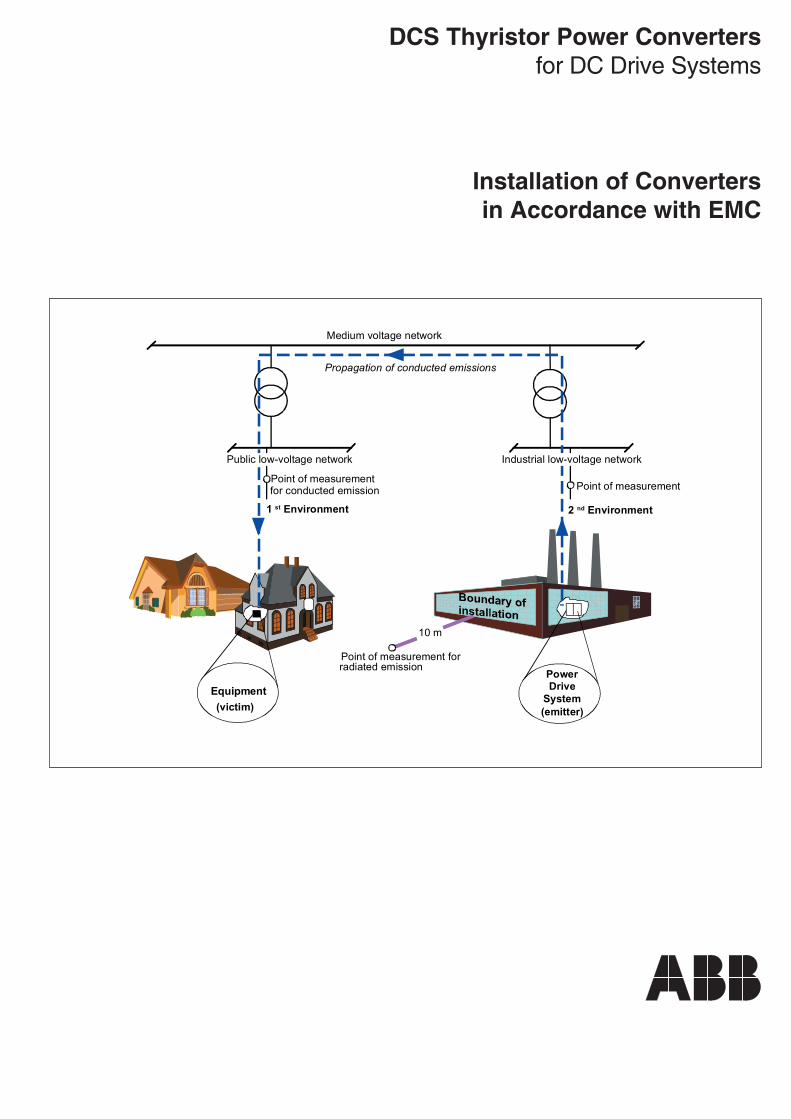
DCS Thyristor Power Convertersfor DC Drive Systems
Installation of Convertersin Accordance with EMC
Medium voltage network
Power Drive
System(emitter)
Equipment(victim)
Point of measurementfor conducted emission
Point of measurement forradiated emission
10 m
2 nd Environment
Point of measurement
1 st Environment
Propagation of conducted emissions
Public low-voltage network Industrial low-voltage network
VII A 1-2
General
3ADW000032R0701_Installation_in_accordance w_EMC_e_g
Contents
VII A INSTALLATION IN ACCORDANCE WITH EMC
1 General
1.1 Introduction ............................................. III A 1-31.1.1 How to use this description ...................................... III A 1-31.1.2 Target group ............................................................ III A 1-3
2 Technical environment
2.1 EMC Compliant Installation and Configurationfor a Power Drive System ....................... III A 2 -1
2.1.1 Introduction ............................................................... III A 2-12.1.2 Definitions ................................................................. III A 2-22.1.3 EMC Compliant Installation Guidelines .................... III A 2-42.1.4 Summary ................................................................ III A 2-14
VII A 1-3
General
3ADW000032R0701_Installation_in_accordance w_EMC_e_g
1.1 IntroductionWhen using DC drives from ABB or any othersupplier there is always basic knowledge re-quired to enable you to understand:
• How your drive needs to be configured andengineered.
• How does your drive installation interact withany other installations surrounding the drive.
• What types of components need to be addedto the converter and why to guarantee thecorrect functionality.
• How need components to be matched.• What needs to be done to be inline with
existing laws and technical standards.
To have some support in to find solutions for allthese problems ABB offers this type of docu-mentation for your assistance.
All other documentation related to ABB's drivesprogram apart from this will be found in thededicated product documentation like SystemDescription, Technical Data, Operating Instruc-tion etc. and is generally available with everysingle drive delivered.
1 General
1.1.1 How to use this descriptionThe purpose of this documentation is to provideprofound general information about drives , theirengineering including additional requirementsfor special accessories, their technical environ-ment as well as basic information of how tohandle modernization of old installations.
1.1.2 Target groupAll users having basic knowledge as well asexperience in practical exercises with DC-Drives.

VII A 1-4
General
3ADW000032R0701_Installation_in_accordance w_EMC_e_g

Technical environment
VII A 2-1
3ADW000032R0701_Installation_in_accordance w_EMC_e_g
2.1 EMC Compliant Installation and Configuration for a Power DriveSystem
2 Technical environment
Practical Installations and SystemsThis manual gives a brief insight of EMC in termsof definitions and offers practical EMC solutionsand a connection example with essential re-marks and hints for the EMC compliance ofpower drive systems. The solutions can be di-rectly used or applied by OEM or Panel builder.
The Directives concerning DrivesThere are three directives that concern variablespeed drives. They are Machinery Directive,Low Voltage Directive and EMC Directive. Themain objective of the EMC Directive is to guar-antee the free movement of apparatus and tocreate an acceptable electromagnetic environ-ment in the European Economic Area (EEA).
Product-specific ManualsThe detailed information of the installation anduse of products can be found in product-specificmanuals included in the product package. Thisguide is meant to be used together with product-specific manuals.
2.1.1 Introduction
GeneralThis guide assists the design and installationpersonnel when intending to achieve compli-ance with the requirements of EMC Directive inthe user’s systems and installations, when usingDCS converters.
The purpose of this chapterThe purpose of this chapter is to guide OriginalEquipment Manufacturers (OEM), System Inte-grators and Panel builders in designing andinstalling DCS converters and their auxiliarycomponents into their own installation and sys-tems. The auxiliaries include EMC filters, linereactors, fuses, etc. If these instructions arefollowed, it is possible to fulfil EMC requirementsand give CE marking when necessary.
DefinitionsThe EMC Product Standard for Power DriveSystems, EN 61800-3 (or IEC 1800-3) is usedas normative standard for variable speed drives.The terms and definitions applied in the stand-ard are also used in this manual. The differenttypes of equipment used in this guide (refer tosection 2.1.2 Definitions) are the same as de-fined in the EMC Directive.
Technical environment
VII A 2-2
3ADW000032R0701_Installation_in_accordance w_EMC_e_g
2.1.2 Definitions
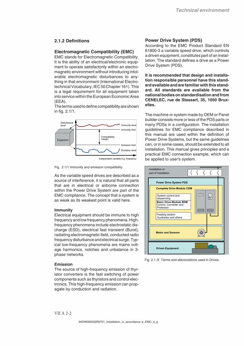
Electromagnetic Compatibility (EMC)EMC stands for Electromagnetic Compatibility.It is the ability of an electrical/electronic equip-ment to operate satisfactorily within an electro-magnetic environment without introducing intol-erable electromagnetic disturbances to any-thing in that environment (International Electro-technical Vocabulary, IEC 50 Chapter 161). Thisis a legal requirement for all equipment takeninto service within the European Economic Area(EEA).The terms used to define compatibility are shownin fig. 2.1/1.
Fig. 2.1/1 Immunity and emission compatibility.
As the variable speed drives are described as asource of interference, it is natural that all partsthat are in electrical or airborne connectionwithin the Power Drive System are part of theEMC compliance. The concept that a system isas weak as its weakest point is valid here.
ImmunityElectrical equipment should be immune to highfrequency and low frequency phenomena. High-frequency phenomena include electrostatic dis-charge (ESD), electrical fast transient (Burst),radiating electromagnetic field, conducted radiofrequency disturbance and electrical surge. Typ-ical low-frequency phenomena are mains volt-age harmonics, notches and unbalance in 3-phase networks.
EmissionThe source of high-frequency emission of thyr-istor converters is the fast switching of powercomponents such as thyristors and control elec-tronics. This high-frequency emission can prop-agate by conduction and radiation.
Immunity level
Immunity limit
Emission limit
Emission level
Disturbance
Compatibilitymargin
Independent variable e.g. frequency
Equipment
level
Power Drive System (PDS)According to the EMC Product Standard EN61800-3 a variable speed drive, which controlsa driven equipment, constitutes part of an instal-lation. The standard defines a drive as a PowerDrive System (PDS).
It is recommended that design and installa-tion responsible personnel have this stand-ard available and are familiar with this stand-ard. All standards are available from thenational bodies on standardisation and fromCENELEC, rue de Stassart, 35, 1050 Brux-elles.
The machine or system made by OEM or Panelbuilder consists more or less of the PDS parts ormany PDSs in a configuration. The installationguidelines for EMC compliance described inthis manual are used within the definition ofPower Drive Systems, but the same guidelinescan, or in some cases, should be extended to allinstallation. This manual gives principles and apractical EMC connection example, which canbe applied to user's system.
Fig. 2.1 /2 Terms and abbreviations used in Drives.
Complete Drive Module CDM
Basic Drive Module BDM
Feeding section
System control and
Power Drive System PDS
Motor and Sensors
sequencing
Installation orpart of installation
Driven Equipment
Auxiliaries and others
Control, Converter andProtection

Technical environment
VII A 2-3
3ADW000032R0701_Installation_in_accordance w_EMC_e_g
Types of EquipmentEMC Directive applies to "all electrical and elec-tronic appliances together with installations con-taining electrical and/or electronic componentsliable to cause electromagnetic disturbance orthe performance of which is liable to be affectedby such disturbance".The interpretation of EMC Directive for differentconfiguration in the area of drives can be dividedinto several levels:
ComponentIn this content the interpretation of componentcan be divided into several categories. If acomponent performs a direct function, as thevariable speed drives do, they are consideredequivalent to apparatus.Direct function:Any function which meets the needs of a userand which can be directly used by such a user,without the need to make any further adjust-ments other than any connections essential forits electrical power supply or for the exchange ofanalogue or digital signals.
ApparatusA finished product containing electrical and/orelectronic components and intended to be placedon the market and/or taken into service as asingle commercial unit.
SystemSeveral items of apparatus combined to fulfil aspecific objective and intended to be placed onthe market as a single functional unit.
InstallationA combination of items of apparatus, equipmentand/or components put together at a given placeto fulfil a specific objective but not intended to beplaced on the market as a single functional unit.
CE Marking for EMCComponents with direct functions, Apparatusand Systems have to be CE marked.Components with no direct function for thefinal consumer are not CE marked.Installations are required to satisfy various bas-es of the Directives, but are not required to beCE marked.
Fig. 2.1/3 The CE mark.
Installation EnvironmentsThe PDSs can be connected to either industrialor public power distribution networks. The envi-ronment class depends on the way the PDS isconnected to the network.The environment classes are First and SecondEnvironment.
First EnvironmentThe First Environment includes domestic premis-es. It also includes establishments directly con-nected without intermediate transformer to alow-voltage power supply network which sup-plies buildings used for domestic purposes.
Second EnvironmentSecond Environment includes all establishmentsother than those directly connected to a low-voltage power supply network which suppliesbuildings used for domestic purposes.
Fig. 2.1/4 Illustration of Environment Classes andpropagation of disturbances.
PropagationFor PDSs in the second environment, the usershall ensure that excessive disturbances are notinduced into low-voltage network, even if prop-agation is through a medium voltage network.
Note! Fig. 2.1/4 shows the case when a victim isin a 1st Environment. The situation is the same ifa victim is in a 2nd Environment in anotherinstallation. The measurements are carried outin that case only in case of dispute.
Medium voltage network
Power Drive
System(emitter)
Equipment(victim)
Point of measurementfor conducted emission
Point of measurement forradiated emission
10 m
2 nd Environment
Point of measurement
1 st Environment
Propagation of conducted emissions
Public low-voltage network Industrial low-voltage network

Technical environment
VII A 2-4
3ADW000032R0701_Installation_in_accordance w_EMC_e_g
2.1.3 EMC Compliant Installation Gui-delines
NoteIn order to make the description in this chapteras short and easily readable as possible, crossreferences in the form 1 , 2 … are used.
GeneralConverters and the major part of the devices,which constitute a DC Drive, cannot fulfil theEMC requirements independently from eachother. They must be installed and connected byskilled personnel according to the guidelineslaid down in this manual. This restriction isrelated to the expression "restricted distribution"in the short description of EN 61800-3, which isthe EMC product standard for a Power DriveSystem.
Definitions
Earth, earthing for safety
Ground, grounding for EMC,connection with chassis or housing withlow inductance
Important instructions for plantswith line filters
Filter in an earthed line (TN or TT Network)The filters are suitable for earthed lines only, forexample in public European 400 V lines. Ac-cording to EN 61800-3, filters are not compati-ble in insulated industrial lines with own supplytransformers due to their safety risks in suchfloating lines (IT networks).
Earth fault detectionFilters (with internal discharging resistors), ca-bles, the converter and the motor have togethera considerable capacitance to ground, whichcan cause an increased capacitive earth cur-rent. The tripping threshold of an earth faultdetector that measures this current must beadapted to this higher value.
High voltage testBecause of the capacitors of the line filter thehigh voltage test has to be done with dc voltageto protect the components.
Warning
Line filters contain capacitors, which can keepdangerous voltages at the terminals after theswitch off of the mains voltage. The dischargeby internal resistors takes some seconds. There-fore a waiting time of at least 10 s and a voltagecheck are obligatory before you begin your workat the equipment.
Product Standard EN 61800-3EMC standard for drive systems (Power-DriveSystem), interference immunity and emis-sions in residential areas, enterprise zoneswith light industry and in industrial facilities.This standard must be complied with in the EUfor satisfying the EMC requirements for sys-tems and machines!
For emitted interference, the following apply:EN 61000-6-3 Specialised basic standard for emis-
sions in light industry can be satis-fied with special features (mains fil-ters, screened power cables) in thelower rating range *(EN 50081-1).
EN 61000-6-4 Specialised basic standard foremissions in industry*(EN 50081-2)
For interference immunity, the following apply:EN 61000-6-1 Specialised basic standard for inter-
ference immunity in residential are-as *(EN 50082-1)
EN 61000-6-2 Specialised basic standard for inter-ference immunity in industry. If thisstandard is satisfied, then the EN61000-6-1 standard is automaticallysatisfied as well *(EN 50082-2).
* The old generic standards are given in brackets
NOTE!
The conformity pro-cedure is matter ofresponsibility ofABB AutomationProducts GmbH andof the machine man-ufacturers or theplant builders corre-sponding to theirshare of the exten-sion of the electricalequipment.

Technical environment
VII A 2-5
3ADW000032R0701_Installation_in_accordance w_EMC_e_g
General safety instructions
Electrical machines or devices are items ofequipment used in industrial power installa-tions. During operation, parts of this equipmentare live and bare, or moving, rotating, etc. Theseparts may cause great material damage andserious heavy injuries, if, for instance, theircovers are removed or if they are not properlyused or operated.
It must therefore be ensured that- only qualified experts perform work at
these machines and devices,- these persons always have available -
among other things - the operatinginstructions and other product-specificdocumentation supplied along whenperforming work, and are obliged to meetthe requirements laid down in thesedocuments,
- non-qualified persons are not authorised toperform any work at or near thesemachines and devices.
The operating instructions cannot take into con-sideration every possible case of configuration,operation or maintenance. Thus, they mainlygive such advice only, which is required byqualified personnel for normal operation of themachines and devices in industrial installations.
If in special cases the electrical machines anddevices are intended for use in non-industrialinstallations - which may require stricter safetyregulations (e.g. protection against contact bychildren or similar) -, these additional safetymeasures must be carried out by the customerduring assembly.
Earth connections must be made according toIEC 364!

Technical environment
VII A 2-6
3ADW000032R0701_Installation_in_accordance w_EMC_e_g
1 Classification
Fig. 2.1/5: Classification
Not applicable
First environment (residential area with light industry) with restricted distribution
Not applied, since general distribution sales channel excluded
satisfied
satisfied
MM
19
4
21
22 23
13
25
18
21
2
21 21
13
25
249 / 249 /
5
Mains filter
Converter
Line reactor
Supply transformer for a residential area (rating normally ≤ 1,2 MVA)
Earthed public 400-V network with neutral conductor
Medium-voltage network
Earthed neutral
To
oth
er
load
s, e
.g. d
rive
sys
tem
s
An isolating transformer with an earthed screen and earthed iron core renders mains filter and line reactor superfluous.
Operation at public low-voltage network
together with other loads of all kinds.
Residential area
To
oth
er
load
s w
hich
hav
e to
be
pro
tect
ed
from
the
syst
em d
istu
rban
ces
caus
ed
by
pow
er c
onv
ert
ers
(HF
inte
rfer
enc
e an
d co
mm
utat
ion
no
tche
s)
Converter
MMMM MM
19
21
22 23
13
25
18
21 21
13
25
4
22 23
14
26
14
26
13
25
13
25
21
18
21 21 21
2 2
4
22 23 22
249 / 249 / 249 / 249 /
5
alte
rnat
ive
alte
rnat
ive
Line reactor + Y-capacitor
Medium-voltage network
Supply transformer for a residential area (rating normally ≤ 1.2 MVA)
Earthed neutral
Earthed public 400-V network with neutral conductor
To
othe
r lo
ads,
e.g
. dr
ive
sys
tem
s
Mains filter
Line reactor
Converter Converter
Mains filter
Line reactor
Converter Converter
An isolating transformer with an earthed screen and earthed iron core renders mains filter and line reactor superfluous.
Operation at public low-voltage network
together with other loads of all kinds.
To
othe
r lo
ads,
e.g
. dr
ive
sys
tem
s
To
othe
r lo
ads
whi
ch h
ave
to b
e pr
otec
ted
from
the
syst
em d
istu
rban
ces
caus
ed b
y po
we
r co
nver
ters
(H
F in
terf
eren
ce a
nd c
omm
utat
ion
notc
hes)
Earthed public 400-V network with neutral conductor
Operation at public low-voltage network together with other loads of all kinds.
Light industry Residential area

Technical environment
VII A 2-7
3ADW000032R0701_Installation_in_accordance w_EMC_e_g
The field supply is not depicted inthis overview diagram. For thefield current cables, the samerules apply as for the armature-circuit cables.
MMMM
19
21 21 21
2
4
13
25
13
25
14
26
14
26
18
22 23 22 23
249 / 249 /
Supply transformer for a residential area (rating normally ≤ 1.2 MVA)
Earthed 400-V network with neutral conductor; 3~ ≤ 400 A
Operation at low-voltage network together with other loads of all kinds, apart from some kinds of sensitive communication equipment.
To
othe
r lo
ads,
e.g
. dr
ive
sys
tem
s
Line reactor + Y-capacitor Line reactor
Converter Converter
Mains filter
Earthed neutral
Medium-voltage network
Industrial zone
alte
rnat
ive
alte
rnat
ive
MMMM
13
25
13
25
14
26
14
26
6
20
4
22 23
249 /
20
21 21
Convertertransformer
Cas
e-re
fere
nced
EM
C a
naly
sis
alte
rnat
ive
Converter transformer with earthed
iron core (and earthed screen where appropriate)
alte
rnat
ive
I > 400 A and/or U > 500 V
Operation with separate power converter transformer. If there are other loads at the same secondary winding, these must be able to cope with the commutation gaps caused by the power converter. In some cases, commutating reactors will be required.
To
othe
r lo
ads,
e.g
. dr
ive
sys
tem
s
Converter Converter
Line reactor
Medium-voltage network
Industrial zone
Legend
Unscreened cable with restriction
Screened cable
EN 61800-3
EN 61000-6-3
EN 61000-6-4
EN 61000-6-2
EN 61000-6-1
satisfied
satisfied
Second environment (industry) with restricted distribution
on customer's request satisfied
Not applicable
Standards

Technical environment
VII A 2-8
3ADW000032R0701_Installation_in_accordance w_EMC_e_g
2 Three-phase filtersEMC filters are necessary to fulfil the standardfor emitted interference if a converter shall berun at a public low voltage line, in Europe forexample with 400 V between the phases. Suchlines have an earthed neutral conductor. ABBoffers suitable three - phase filters for 400 V and25 A...600 A and 500 V filters for 440 V linesoutside Europe (see System description / Tech-nical data).
Lines with 500 V to 1000 V are not public. Theyare local lines inside factories, and they do notsupply sensitive electronics. Therefore convert-ers do not need EMC filters if they shall run with500 V and more (see also 6).
3 Single-phase filters for field supply
Many field supply units are single - phase con-verters for up to 50 A excitation current. Theycan be supplied by two of the three input phasesof the armature supply converter. Then a fieldsupply unit does not need an own filter as shownat the connection example (24).
If the phase voltage to the neutral conductorshall be taken (230 V in a 400 V line) then aseparate filter is necessary as shown below.ABB offers such filters for 250 V and 6...55 A(see System description / Technical data).
3-PH FILTER
1-PH FILTER
ML1L2L3
N
Fig. 2.1/6 Connection of single and three phase filters
4 Line reactors (Commutation reactors)
Converters cause short-duration short circuitsat their AC inputs, so - called commutationnotches. Such notches down to 0 V (100%depth) can be accepted at the secondary wind-ings of converter (dedicated) transformers (op-eration without line reactors). However, theirdepth must be reduced if the same transformershall supply more than one converter. In suchcase line reactors are necessary. They mustcause about 1% relative voltage drop at ratedcurrent. So - called 1% reactors are also neces-sary if the power of the converter is very lowcompared with the available power of the trans-former or supply line. ABB offers suitable 1%
reactors.According to the European product standard EN61800-3, the commutation notches must bekept below 20% of the line voltage in the firstenvironment, whereas an upper limit of 40 % isspecified for the second environment. This tar-get can be achieved with the aid of line reactors.The inductance of these reactors to be appliedin the first environment must have 4 times thevalue of the network inductance at the convert-er's connection point (point of common cou-pling, PCC) as shown in fig. 2.1/7. Therefore inmany cases so-called 4% reactors are neces-sary, and therefore ABB offers also suitable 4%line reactors besides the 1% reactors (see Sys-tem description / Technical data).
Due to the maximum power of public 400 Vtransformers(PMAX = 1.2 MVA IMAX = 1732 A) and dueto their relative short circuit voltage VSC of 6%or 4% the maximum AC current which is availa-ble for a converter is 346 A or 520 A (IDC ≤ 422 Aor 633 A).
XPCC
Converter
Supply transformer of a residental region with light industry (rated power normally ≤ 1.2 MVA). With reference to EN 61800-3 the rated power of transformer must be at least 4 times the rated power of the PDS.
Earthed public 400 V line with neutral conductor
Earthedstar point
Medium-voltage line
Line choke
PCCNotches ≤ 20 %
vSC = 4 % or 6 %
Imax = 1.7 kA
For vSC = 4 %: XPCC ≥ 5.40 mΩ (LPCC ≥ 17.2 µH)
For vSC = 6 %: XPCC ≥ 8.12 mΩ (LPCC ≥ 25.8 µH)
For vSC = 4 %: XCHOKE ≥ 4 x XPCC = 21.6 mΩ (LCHOKE ≥ 68.8 µH)
For vSC = 6 %: XCHOKE ≥ 4 x XPCC = 32.48 mΩ (LCHOKE ≥ 103.2 µH)
Example:
2
*nom
nomPCCSCPCC PVvX ≥
%20≤+ CHOKEPCC
PCC
XXX
PCCCHOKE XX *4≥⇒
For vSC = 4 %: IDC ≤ 633 A
For vSC = 6 %: IDC ≤ 422 A
Fig. 2.1/7 Required minimum line reactorimpedance for installation of converter in first environment
Often the maximum current is not limited by thetransformer but by the power cable to the indus-try region. Therefore it is necessary to ask theenergy supply company concerning the lineimpedance and the current which is available atthe desired point of common coupling (PCC).
Technical environment
VII A 2-9
3ADW000032R0701_Installation_in_accordance w_EMC_e_g
5 Separation transformers
A separation transformer makes line reactorsunnecessary because of its leakage induct-ance, and a grounded screen between its wind-ings saves an EMC filter, see 1 and 4. Thescreen and the iron core must be well connectedwith the mounting plate of the converter. If thetransformer is located outside the convertercubicle the screen of a screened 3-phase cablemust make this connection.
6 Converter (dedicated) transformers
A converter (dedicated) transformer transfershigh power directly from a medium voltage lineto a single large converter or to a local lowvoltage line for several converters (see 20).Furthermore it acts as separation transformer.
If such a converter transformer has no screenthe EMC demands are nevertheless fulfilled inmost cases because the RF interference energycan hardly get via the medium-voltage line andthe transformer of the public line to the loadswhich must be protected against pertubances.In the case of a dispute a measurement must bedone at the point of common coupling (publiclow - voltage line) according to EN 61 800-3.
7 Installation hints
8 Cabinets
All metal cubicles available on the market can beused; however, their mounting plates must havewell conducting surfaces according to 9. If adrive system is placed in more than one cubicletheir mounting plates must be connected bybroad pieces of well conducting sheet metal.
9 Mounting plate
The mounting plate must be made from steelwith zinc surfaces and without any painting. ThePE copper bar must be mounted directly on themounting plate without any insulating meansbetween, and it must be connected with theplate by several bolts distributed in equal dis-tances along its length.
10 Placement of devicesThe converter, the line reactor, fuses, contac-tors and the EMC filter are to be placed on themounting plate so that the connections can be
made as short as possible, especially thosefrom the converter via the line reactor to the filter,and that the requirements in 15 can be fulfilled.The surface of the components to be mountedon the mounting plate has to be free of coatingmaterial (see 28).
11 Screening
12 Signal cables
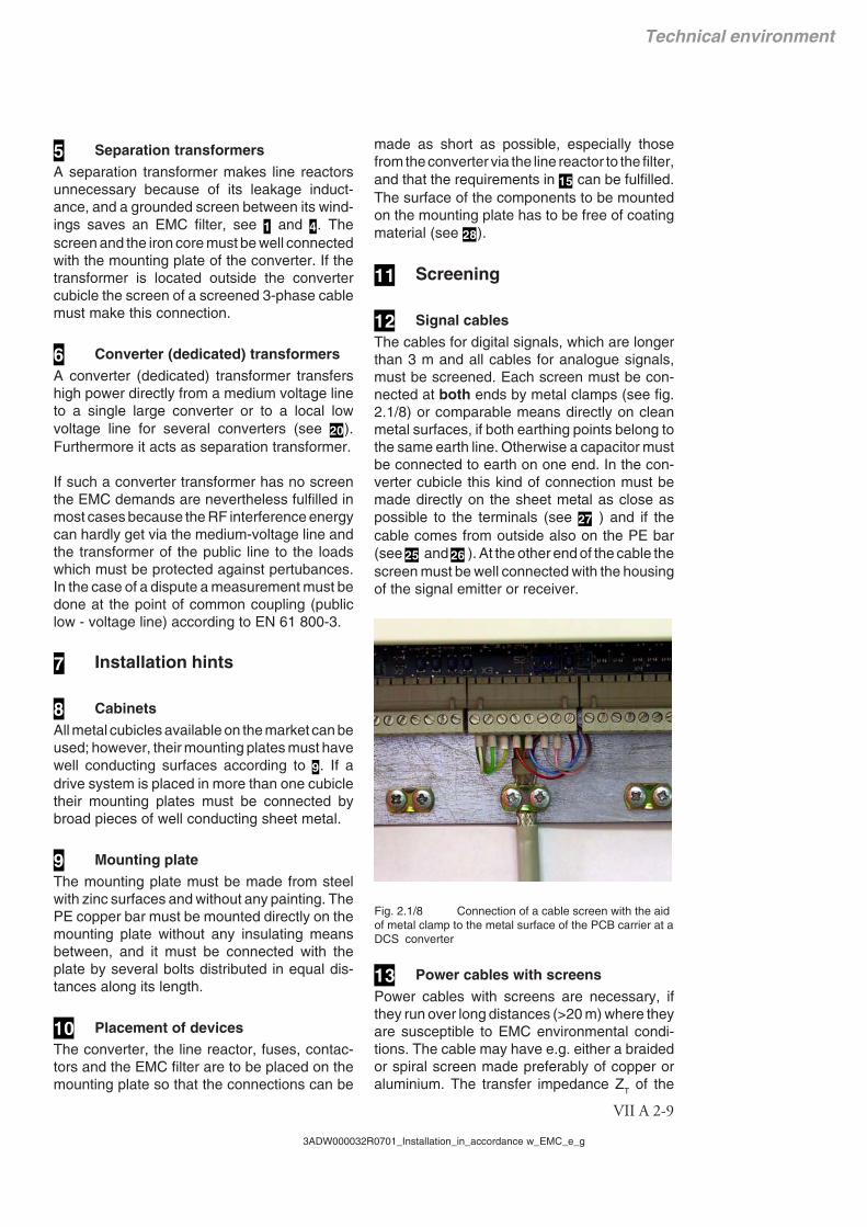
The cables for digital signals, which are longerthan 3 m and all cables for analogue signals,must be screened. Each screen must be con-nected at both ends by metal clamps (see fig.2.1/8) or comparable means directly on cleanmetal surfaces, if both earthing points belong tothe same earth line. Otherwise a capacitor mustbe connected to earth on one end. In the con-verter cubicle this kind of connection must bemade directly on the sheet metal as close aspossible to the terminals (see 27 ) and if thecable comes from outside also on the PE bar(see 25 and 26 ). At the other end of the cable thescreen must be well connected with the housingof the signal emitter or receiver.
Fig. 2.1/8 Connection of a cable screen with the aidof metal clamp to the metal surface of the PCB carrier at aDCS converter
13 Power cables with screens
Power cables with screens are necessary, ifthey run over long distances (>20 m) where theyare susceptible to EMC environmental condi-tions. The cable may have e.g. either a braidedor spiral screen made preferably of copper oraluminium. The transfer impedance Z
T of the
Technical environment
VII A 2-10
3ADW000032R0701_Installation_in_accordance w_EMC_e_g
power cable must be less than 0.1 Ω/m in thefrequency range up to 100 MHz, in order toensure an effective reduction of emission and asignificant increase of immunity. The screenmust be pressed by a well conducting metalclamp directly against the mounting plate or thePE bar of the converter cubicle (see 24). Anotherconnection option is via EMC sleeve.
There the contact surface shall be clean and aslarge as possible. The PE wire can be connect-ed with a normal cable socket at the PE bar.Screened cables to the armature and to theexcitation winding cause the lowest noise level.
14 Power cables without screens
If a screen is not necessary (see 13) the arma-ture current cable must be a four-wire cablebecause two wires are needed as conductorsfor the parasitic RF currents from the motor tothe RF filter in the cubicle. The unscreened fieldcurrent cable F must be installed directly alongthe armature cable A as shown in fig. 2.1/9. A 2-wire cable is sufficient.
PE
PE
AF
Fig. 2.1/9 Cross-sectional view of arrangement offield current cable F and armature cable A.
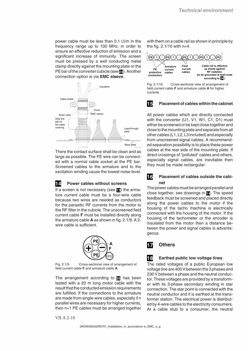
The arrangement according to 26 has beentested with a 20 m long motor cable with theresult that the conducted emission requirementsare fulfilled. If the connections to the armatureare made from single-wire cables, especially if nparallel wires are necessary for higher currents,then n+1 PE cables must be arranged together
with them on a cable rail as shown in principle bythe fig. 2.1/10 with n=4.
PE + PE- + PE- + PE- + PE-
Fieldcurrentcables
Armaturecurrentcables
PEprotective
conductors
Cable rail is effectiveas shield against
RF radiation(to be grounded at both ends
according to 24 )
Fig. 2.1/10 Cross-sectional view of arrangement offield current cable F and armature cable A for highercurrents
15 Placement of cables within the cabinet
All power cables which are directly connectedwith the converter (U1, V1, W1, C1, D1) musteither be screened or be kept close together andclose to the mounting plate and separate from allother cables (L1, L2, L3 included) and especiallyfrom unscreened signal cables. A recommend-ed separation possibility is to place these powercables at the rear side of the mounting plate. Ifdirect crossings of "polluted" cables and others,especially signal cables, are inevitable thenthey must be made rectangular.
16 Placement of cables outside the cabi-net
The power cables must be arranged parallel andclose together, see drawings in 14. The speedfeedback must be screened and placed directlyalong the power cables to the motor if thehousing of the tacho machine is electricallyconnected with the housing of the motor. If thehousing of the tachometer or the encoder isinsulated from the motor then a distance be-tween the power and signal cables is advanta-geous.
17 Others
18 Earthed public low voltage linesThe rated voltages of a public European lowvoltage line are 400 V between the 3 phases and230 V between a phase and the neutral conduc-tor. These voltages are provided by a transform-er with its 3-phase secondary winding in starconnection. The star point is connected with theneutral conductor and it is earthed at the trans-former station. The electrical power is distribut-ed by 4-wire cables to the electricity consumers.At a cable stub to a consumer, the neutral
EMC sleeve
Lead-through plate
Strip this part of the cable covering
Base plate
Strain relief
Cover
Cable shield
Insulation
sleeve.dsf

Technical environment
VII A 2-11
3ADW000032R0701_Installation_in_accordance w_EMC_e_g
conductor must be earthed (local earth of thehouse or plant), and then it is split into a neutraland a PE conductor. Therefore a 3-phase loadwith neutral conductor must be supplied by a 5-wire cable. Converters, however, are 3-phaseloads which do not need the neutral conductor inmost cases. They can be supplied by 4-wirecables as shown in fig. 2.1/5. The change fromthe earthed neutral conductor outside the house,plant or factory to the internal PE conductor withthe local earthing point between is not shown inthis figure. Power limitation: see end of section4!
19 Public low voltage lines in industrial
regionsIn an industrial region the noise level which iscaused by converters is allowed to be 10 dBhigher than in a residential region with includedlight industry. Therefore the protection targetsconcerning EMC can be met without screenedmotor cables if these cables are configuredaccording to 14.
A public low voltage line of an industrial regionmay have an own supply transformer as shownin fig. 2.1/5, but often the lines of an industrialregion and of a residential one are supplied bya common transformer. This depends on thepower consumption of both regions and on theirdistance. Power limitation: see end of 4!
The dashed line between the lines of both re-gions indicates the version with only one trans-former. This dashed line represents a powercable from the transformer at the right to theindustrial region at the left. The power cable isimportant also for the EMC. Due to its length itreduces the noise level by at least 10 dB from theindustrial to the residential region.
20 Industrial low voltage lines
Industrial low voltage lines are local lines inplants or factories. They have own supply trans-formers (see 6). In most cases they are insulat-ed (IT network / no earthed star point) and theirvoltages are often higher than 400 V. The loadstolerate higher noise levels. Therefore and be-cause industrial lines are decoupled from publiclines by their transformers and distances, con-verters do not need EMC filters at industrial low-voltage lines (see 6). Problems for other loads
on the same line caused by commutation notch-es can be solved with the aid of line reactors (see4).
Insulated lines must have also an earth conduc-tor. The earth conductor is important for thefeedback of parasitic RF noise currents from theDC motor via the converter to the earth point ofthe supply transformer of the line. Without sucha conducted feedback the loop of the parasiticRF noise current is closed via the earth with theresult that roving parts of this current can inter-fere with electronic equipment far away from thedrive.
21 Fuses at the stubs from the low volt-age line
At the stubs the cross-sections of the conduc-tors become lower than in the main cable. There-fore fuses are prescribed which are adapted tothe reduced cross section, and they must belocated close to the stubs. This principle must berepeated at each reduction of the cross sectionfrom the stub at the main cable via the distribu-tion net in a house or factory down to theconnection point of a converter. The resultingfuse hierarchy is not shown in fig. 2.1/5. Only thefuses of the lowest rank are mentioned.
22 Fast FusesThe converters are protected against overloadby their control systems. Therefore dangerousovercurrents can be caused only by faults in theconverters themselves or in the loads. In suchcases the thyristors can be protected only withthe aid of special fast fuses. Such fast fuses areshown directly at the AC connection points of theconverters in fig. 2.1/5 as well as in the connec-tion example, with more details, at the beginningof 24. But fast fuses outside the converters arenecessary only for units of the lower powerrange. Larger converters comprise the fast sem-iconductor fuses.
23 Stub for auxiliary devicesExamples for auxiliary devices: field supply con-verters, transformers, fan motors.
24 Connection example in accordancewith EMCSee fig. 2.1/11.

Technical environment
VII A 2-12
3ADW000032R0701_Installation_in_accordance w_EMC_e_g
25 Armature and field cables with screensfor "first environment"See fig. 2.1/11.
26 Armature and field cables withoutscreens for "second environment"See fig. 2.1/11.
27 Encoder inputs and analogue I/OSee fig. 2.1/11.
Remarks
28 Internal ground connections
Additionally to the PE connections good HFconnections to ground must be realised with theaid of a mounting plate which has a well con-ducting surface (sheet metal from zinc-platedsteel for example). This means, the housings ofall components like the line filter and the con-verter must be pressed directly to the mountingplate by at least four fixing bolts. The seatingsurfaces of the housings must be free from nonconducting coating. These ground connectionsare indicated in the drawing at the top by thefollowing symbol (symbol often used to indicatemass or chassis):
The PE bar must be connected with the mount-ing plate by many bolts, which are distributedalong its whole length with equal distances.That's the reason the above symbol is usedseveral times in the drawing.
29 Earth connectionsAll devices are connected with the PE bar by themounting plate and also by PE conductors. ThePE bar is earthed via the PE conductor of the 3-phase power cable.
Protective earth (PE) connectionsThe drive shall be earthed only by the earthconductor of the line cable. This serves forprotection reasons and is indicated by the fol-lowing symbol:
An additional local earthing, especially at themotor, raises the level of the RF noise on the linecable.
Earth connections between motor and driv-en machineThe earth of a grounded machine must beconnected to the earth of the driving motor, inorder to avoid floating potential.
Thermal motor protectionIt is recommended that the cable of thermalmotor protection device is fed through an appro-priate filter at the point of entry into cubicle, inorder to suppress EMC disturbances.

Technical environment
VII A 2-13
3ADW000032R0701_Installation_in_accordance w_EMC_e_g
Fig. 2.1/11 Connection example in compliance with EMC
Important hintThe example shows the principle structure of a DC drive and its connections. It is not a bindingrecommendation, and it cannot respect all conditions of a plant. Therefore each drive must beconsidered separately and with respect to the special application. Additionally the generalinstallation and safety rules must be taken into account.
A F
C1/D1 F+/F-
M
A1 A2
F1
F2
A1 A2
F1
F2
L1
L2
L3
U1
V1
W1C1
D1
U1
V1 F-F+
PE
PE
PE
PE
A
F
A F
T
AF
AF
C1/D1 F+/F-
PE
PE
I/O
Mounting plate
DC motor
Tac
ho
ScreensContact to the motorhousing at the whole
screen perimeter
Filter
Mounting plate with PE busbar and terminals
DC motor
Tac
hoS
cree
n
Fieldsupplyunit
Armature and field cables with screens for
"first environment"
Armature and field cables without
screens suitable for "second
environment"
Hint: The armature current cable must contain a third wire for a PE connection if the copper cross section of the screen cannot fulfil the PE safety demands.
terminals on the CON-x board
Mounting plate with PE busbar and terminals
terminals on the CON-x board
inte
rmed
iate
term
inal
s
pre
fere
d s
olu
tio
n
PE bar
to filter, choke...
directly to
lower edgeof the PCB
carrier
TachoEncoder, analogue I/O,and digital I/O (>3 m)
TachoEncoder, analogue I/O,and digital I/O (>3 m)
directly to
lower edgeof the PCB
carrier
to filter, choke...
inte
rmed
iate
term
inal
s
pre
fere
d s
olu
tio
n
PE bar

Technical environment
VII A 2-14
3ADW000032R0701_Installation_in_accordance w_EMC_e_g
2.1.4 Summary
EC Declaration of Conformity for DCSConvertersAn EMC declaration of conformity covering DCSconverters verifies that they comply with theprovisions of the European Low Voltage andEMC Directives (Directive 73/23/EEC, as amend-ed by Directive 89/336/EEC and 93/68/EEC).
Compliance with the EMC DirectiveThe EMC Directive defines the requirements forimmunity and emissions of electrical equipmentused in the European Economic Area (EEA).The EMC product standard EN 61800-3 coversthe requirements stated for thyristor power con-verters. DCS thyristor power converters complywith the EMC Directive in industrial low voltagenetwork (up to 1000 V; also IT network), publiclow-voltage network in industrial regions and inearthed public low voltage network (restricteddistribution) with the provisions summarised inthe following three subsections.
Industrial Low-Voltage Network1. Industrial low voltage lines are local lines
in plants or factories with their own supplytransformers (with earthed iron core),which decouple the industrial lines fromthe public lines. EMC filters are thereforenot needed in industrial low voltage lines.
2. If static screening between primary andsecondary windings of the supply trans-former is present, it must be earthed inorder utilise the filtering effect.
3. Problems caused by commutation notchescan be solved by insertion of appropriateline reactors.
4. The motor and control cables of the DCSconverter must be installed in accordancewith the specifications outlined in section2.1.3 - Installation hints 7 of this chapter.
Note: The DCS converter must not be equippedwith EMC filter (refer to section 2.1.3 - Generalof this chapter) if installed in floating networks(IT-Network). The mains become connected toearth potential through the EMC Y filter capac-itors. This may cause danger or cause damageto the unit. Furthermore a floating network is notpublic. Therefore higher noise levels are al-lowed.Note: If screened motor cables are not availabledue to very high rated armature current, strictadherence to section 2.1.3 - Power cables with-out screens in this chapter is required.
Public Low-VoltageNetwork in Industrial Regions1. The DCS converters must be equipped
with EMC filters (refer to publicationTechnical data for appropriate filter ratings)and line reactors.
2. The motor and control cables of the DCSconverter must be installed in accordancewith the specifications outlined in section2.1.3 - Installation hints of this chapter.
Note: If screened motor cables are not availabledue to very high rated armature current, strictadherence is required to section 2.1.3 - Powercables without screens of this chapter.
Earthed Public Low-Voltage Network (Re-stricted Distribution)1. The DCS converters must be equipped
with EMC filters and line reactors.2. The motor and control cables of the DCS
converter are basically screened.3. In case a separation transformer is ap-
plied, its screen and iron core must begrounded. If no static screen is present, anappropriate filter must be used.
C-Tick Marking for DCS ConvertersA "C-Tick" mark is attached o each variablespeed drive in order to verify compliance withthe relevant standard ("IEC 61800-3 (1996) -Adjustable speed electrical power drive sys-tems - Part 3: EMC product standard includingspecific test methods"), mandated by the Trans-Tasman Electromagnetic Compatibility Scheme.
Definitions
EMC stands for Electromagnetic Compatibili-ty. It is the ability of electrical/electronic equip-ment to operate without problems within anelectromagnetic environment. Likewise, theequipment must not disturb or interfere withany other product or system within its locality.
The Trans-Tasman Electromagnetic Compati-bility Scheme (EMCS) was introduced by theAustralian Communication Authority (ACA)and the Radio Spectrum Management Group(RSM) of the New Zealand Ministry of Eco-nomic Development (NZMED) in November2001. The aim of the scheme is to protect theradiofrequency spectrum by introducing tech-nical limits for emission from electrical/elec-tronic products.

Technical environment
VII A 2-15
3ADW000032R0701_Installation_in_accordance w_EMC_e_g
First environment includes establishmentsconnected to a low-voltage network, whichsupplies buildings used for domestic purpos-es.
Second environment includes establishmentsconnected to a network not supplying domes-tic premises.
Restricted distribution: mode of sales distribu-tion in which the manufacturer restricts thesupply of equipment to suppliers, customersor users who separately or jointly have techni-cal competence in the EMC requirements ofthe application of drives.
Unrestricted distribution: mode of sales distri-bution in which the supply of equipment is notdependent on the EMC competence of thecustomer or user for the application of drives.
Compliance with IEC 61800-3
First environment (restricted distribution)The drive complies with the limits of IEC61800-3 with the following provisions:
1. The drive is equipped with an EMC filter.2. The drive is installed according to the instruc-
tions given in figure 2.1/5.3. The motor and control cables used are select-
ed as specified in figure 2.1/5.4. Maximum cable length is 100 meters.
Notes:The drive must not be equipped with the EMCwhen installed to IT (unearthed) networks. Themains become connected to earth potentialthrough the EMC filter capacitors. In IT systemsthis may cause danger or damage the unit.
Second environmentThe drive complies with the limits of IEC61800-3 with the following provisions:
1. It is ensured that no excessive emission ispropagated to a neighbouring low-voltagenetwork (refer to figure 2.1/4 and 2.1/5). Insome cases, the natural suppression in trans-formers and cables is sufficient. If in doubt theuse of EMC filters and/or supply transformerswith static screening between primary andsecondary windings is strongly recommend-ed.
2. The drive is installed according to the instruc-tions given in figure 2.1/4 and 2.1/5.
3. The motor and control cables used are select-ed as specified in figure 2.1/4 and 2.1/5.

Technical environment
VII A 2-16
3ADW000032R0701_Installation_in_accordance w_EMC_e_g
3AD
W 0
00 0
32 R
0701
RE
V G
11_2
003
ABB Automation Products GmbHPostfach 118068619 Lampertheim • GERMANYTelefon +49(0) 62 06 5 03-0Telefax +49(0) 62 06 5 03-6 09www.abb.com/dc
*032R0701A3450000**032R0701A3450000*