ddc •cl~ss,,,v {• jul 2,,6 z 1 - dtic.mil when the spring loaded valve is pushed ... the...
TRANSCRIPT

) UNCLASSIFIED
Contractor: Westinghouse Electric Corporation
Underseas Divisiop
Contract No: DA-18-035-A2C-123(A)
FIRST QUARTERLY PROGRESS REPORT
COVERING THE PERIOD
April 1, 1964,thru June 30, 1964
WATER INTAKE AND RESUSCITATION EQUIPMENT
FOR PROTEC'TIVE MASKS
Vrepared By: O Approved By: ____________
E. D. Lejg,-tn)(ineer E. R. Hess, Sups. Enginee:
DATE: July 15, 1964
DDC
•cL~sS,,,V {• JUL 2,,6 Z 1UNCLASSIFIED
: SF
DOC.IRA 8

BestAvai~lable
Copy

1. INTRODUCTIOH
The purpose of the contract is to develop low cost highly reliable
equipment to be used in service protective masks which will allow the soldier
in the field to drink water and to resuscitate battle field casualties while
masked in a CB contaminated atmosphere. There is no such equipment in use at
the present time, so that th2 specific design of the equipment will depend
upon laboratory and field testing data obtained during the course of the
program.
The program is divided into three phases:
1. Development - up to 3 models of three units each
2. Prototype - 6 units of best development model
3. Pre-production - 36 units of improved prototype
This report covers a portion of the first phase.
J1

I1. DEVELOPMENT AND FABRICATIcIN
The development of water intake equipment under this contract was begun
I April 1964. At that time Westinghouse (W) personnel met with persons from
the Chemical Research Development Laboratories (CRDL) to review the work done
by CRDL on this equipmint.
Two designs have been investigated by CRDL. The first was the use of a
probe attached Lu the canteen which could be in3erted into the protective
mask when the soldier desired water. The proposal for work under this contract
was based upon this design. The greatest objection to this design was the
relatively long time required to insert and remove the probe from the mask.
During this time the soldier is so cccupied with drinking that he is not
capable of any offensive action, or even able to defend himself.
To reduce the amount of time required for drinking and thus better protect
the man, a second design was developed. This device had a permanently mounted
drinking tube inside the mask which extended through and outside the mask end-
ing in a quick disconnect type coupling. The canteen had a flexible tube
attached to it terminating in a quick disconnect type coupling that mates with
the mask coupling. The tubing was long enough so that the canteen may stay
on the wearers hip during the drinking process. Each coupling had a valve to
prevent the entrance of contaminated air. When the canteen tubing was con-
nected to the mask tubing, the valves were opened and water could be sucked
up. In case of emergency, the connection could be quickly broken and since
it was self-sealing, it provided complete protection for the man.
2
-. low

One problem with this design was that the mouthpiece was fixed and remained
in the man's mouth all the time. Both Westinghouse and CRDL went to work to
find a means of keeping the mouth piece out of the man's mouth, yet provide a
means for getting it into his mouth when he desired to drink water or
resuscitate.
Three approaches were investigated to provide a means for moving the mouth
piece.
1. Attach a support for the flexible tubing to the nose cup so that by
pressing on the mask nose the support moves the flexible tube and
mouth piece into the rar's mouth. The elaiticity of the nose cup and
Gmsk retracts the moutb oiece when the nose piece is released.
2. Attach the flexible tubing support to a shut-off valve mounted in the
voice mitter assembly plate. When the spring loaded valve is pushed
into the mask approximately 1/2 inch, the mouth piece moves into the
man's mouth. Releasing the valve causes the mouth piece and flexible
tubing to retract.
3. Moving the mouth piece and tubing into the mouth by means of a linkage
mounted on the resuscitation check valve housing. The linkage is
actuated by pulling the shut-off valve out approximately 7/32 inch.
This moves the mouth piece into the man's mouth and opens the water
passage. Releasing the shut-off valve shuts off the flow of water.
In this design the mouth piece retraction is dependent upon the
springiness of the flexible tubing. There Is no positive means for
retracting the mouth piece because for resuscitation it is necessary
to have the south piece in the mouth yet have the shut-off valve closed.
- -- !-I
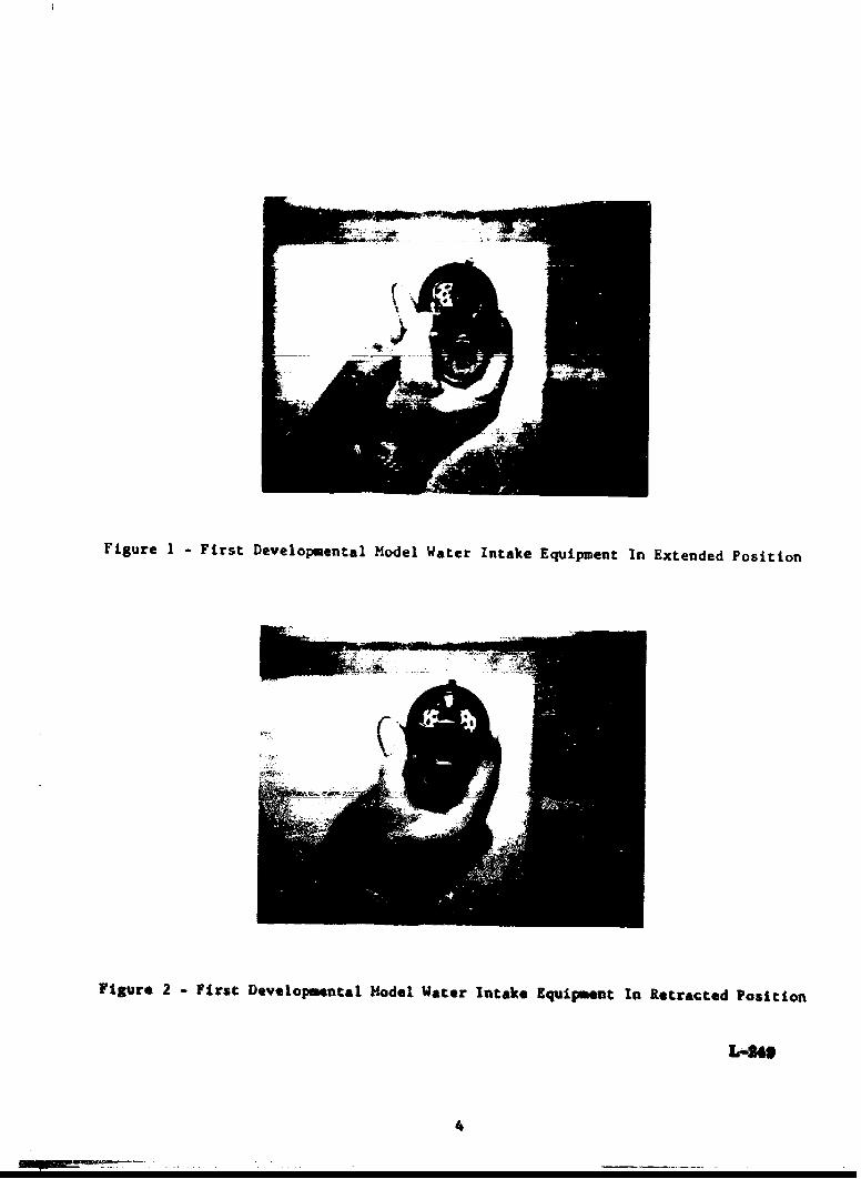
Figure 1 -First Developmental Model Water Intake Equipment In Extended Position
Figure 2 -First Developmental Model Water Intake Equipment In Retracted Position
L-2"
4

/ -AFigure 3 - First Developmental Model Water Intake Equipment Installed In Protective Mask
igure 4 -General View of Leakage Testing Equipment Showing Detector (Lett) and Testing
Chamber (light)
!LOW
5 1

It was agreed that the first development model scheduled for 1 June 1964
delivery would be based on the third approach. A photo of this model is shown
by Figures 1 and 2. Figure 3 shows this model instel1ed in a mask. The plastic
canteen was used for this group of three units and was modified by the installa-
tion of a fitting in the canteen cap to which the tubing extending to the mask
is attached. There is a short length of tubing with a weight on one end attached
to the inside of this fitting. The tubing will be stowed in a pocket snapped
to the outside of the canteen cover.
The first group of development models was fabricated chiefly from brass
material by principally machining operations. Brass was selected because of
its ease in fabrication. Soft wire was used to enable some adjustment of the
parts during the testing and evaluation phases. The materials used for the
later models will be selected to meet the expected service and environmental
requirements, and be compatible with lowest cost production methods and
processes.
The first three models were delivered to CRDL on 4 June 1964. These models
were studied by humaun factors personnel and their coments on this design are:
1. The pulting action of the shut-off valve tends to break the mask to
face seal by pulling the mask away from the face thus exposing the
wearer to the contaminated atmosphere. To overcome this problem the
valve should be redesigned to operate with a rotary notion instead
of pulling action.
2. The inside diameter of the water tubing connecting the canteen and mask
Is too mall* thus requiring too such time to drink the water. The
S68

answer to this is to increase the uinimum size of water passage froe
3/32 inch diameter to 1/8 inch diameter.
3. There is or will be a tendency of the tubing that connects the canteen
to the mask to kink or otherwise shut off the flow of water. Make the
tube out of a material loss subject to kinking or increase the wall
thickness of the tubing or both to prevent kinking.
4. Some more thought should be given to the problem ot storage of the
tubing and its attachment to the canteen. The tubing should be
attached to the canteen by means other than through the cap. This
will allow use of the canteen in a normal manner without interference
from the water drinking equipment. Another possible solution is to
have the tubing separate from the canteen and be stored separately,
then plugged into both the canteen and mask when desired to drink.
In answer to the first human factors objection, the design of the second
development model will incorporate a shut-off valve using rotary action.
Rotary motion of the valve will actuate the mouth piece through a pair of
miter gears. Three units of this model are scheduled for delivery to CRDL
on I August 1964.
DEVELOPMENT OF TEST EQUIPMIET AND TESTING
The models built under this contract are being teasted by Westinghouse to
insure that the introduction of the water intake equipment into the protective
mask will not add to the mask leakage. The total leakage permitted during 5
attachments and detachments of the water tubing and mask is 5 parts per million
(PPM) air. Additional testing such as vapor and particulate leakage tests

vili be performed by the Government and these results will be used to determine
future design.
The detection of leakage at such low rates presents a problem in finding
a means of sufficient sensitivity so that such leakage may be measured. The
Westinghouse Electronegative Gas Detector (EGAD) is of the required sensitivity
and was used in the leakage testing. This detector uses the electron capture
technique and is able to detect concentrations of gas as low as 1 part in 10
million. The sensitivity of the detector varies with the various gases and has
a range from one part up to 100 parts per million. The gas used in this test-
ing is Freon C-318 which the detector is most sensitive to. The EGAD has a
meter which gives a direct reading of the concentration of the gas in parts
per million.
The detector and test chamber fabrication is shown by Figure 4. The
chamber actually consists of two chambers which may be called the detection
chamber and freon chamber. In Figure 4, the detection chamber is shown on
the left with the detector probe inserted. The clear plastic portion of the
chamber is the freon chamber. Figure 5 shows the freon chamber which can be
detached from the detection chamber in order to change cover plates on the
detection chainber. There are two cover plates; one for testins voice mitter
assemblies and the second with head form so that the mask and complete assembly
may be tested. The head form is positioned upside down so that the masks can
be placed on it easier. There is a fan in the detection chamber to prevent
stratification aad to insure good mixing. The two gloves shown in the freon
chamber allow the water iutake devices to be operated without reducing the
m m m

Figure 5 -Freon Chamber 1n Open Positzion Ready To Load Mask For Testing
figure 6 -Freon Chamber Closed, )IAu~ On, Test In Progress, Shut Off Valve Being Operated

concentration of the freon in the chamber.
To test a voice mitter assembly or mask the proper cover is selected and
attached to the detection charber. The freon chamber is then secured to the
detection chamber. Pl1ce the nart to be tc,-ted in the freon chamber, shut the
door and inject the prop.er quantity of i reon u-3l8 into the chamber. This is
shown by Figure 6. The detection chamber pressure is reduced by 6 inches of
water and held for the specified length of time. When ready to determine the
leakage, the pressure is increased to atmospheric and the detector probe
inserted into the detection chamber. This gives an indication on the meter of
the number of parts per million freon in the detection chamber.
The leakage allowed by the contract is expressed as a rate of l1 .age
whereas the leakage read by the detector is a btatic concentration. To
correlate the two, the concentration of freon in the freon chamber must be
specified. The allowable leakage of 5 PPM is equivalent to .05 cc per minute
leakage. A concentration of 100 PPM is used 0i the freon chamber since this
is the largest that can be checked by the EGAD. Uith this concentration of
Freon, 0.01% of the mixture is Freon. If this is multiplied by the leakage
rate of .05 cc per minute, the result is .0005% Freon should leak into the
detection chamber per minute if the leak were the greatest allowable. This
percentage is the same as 5 PRM so a concentration of 100 PPM in the freon
chamber is equal to a reading on the EGAD of 5 PIM.
Another test made on the models was the simulated drinking test. A suction
of 60 to 100 mm of mercury was applied to the water mouth piece. The water is
10

run into a graduated flask so that the volume of water moved through the system
can be measured. A venting valvi is added to the system to shut off the vacuum
and open the drinking passage to ambient air pressure to break the vacuum
occuring when water is removed from the sealed canteen and flow stops.
The test results of the three mask systems of the first development model
are as follows:
LEAKAGE IN PARTS PER MILLION (PPM)
SYSTEM 1 2 3
VOICE MITTER
ASSEMBLY 1.0 0.9 0.8
(MoDIFIED) I
MASK* 3.0 3.4 3.2
MASK AND
VOICE MITTER 3.8 4.5 4.0
ASSEMBLY
* GFM M-17 Mask tested prior to replacing voicemitter with modified voicemitter.
The following information has been received from Government testing and
evaluation of the first models.
1. The masks were tested in the gas chamber using CN gas and no leakage
was noted.
2. Water was drunk satisfactorily through the mask while in the gas
chamber.
3. A test of the resuscitation ability of the system was satisfactorily
conducted.
11

4. It takes 14 minutes to empty a canteen full of water. The drinking
rate for future models should be reduced to 10 minutes.
5. The exhalation resistance was somewhat higher than normal due to
resistance of the resuscitation check valve.
6. The drinking tube was too long since it hit the wearers nose.
7. On two occasions the mask to face seal was broken by pulling too hard
on the shut-off valve.
8. One unit had the wire that supports the bellows tubing come loose from
the hub. The wire was re-soldered to the hub and testing continued.
9. On one system the drinking mouth piece came off the tubing and the
resuscitation mouth piece came about half-way out of the bellows tubing
after about 2 1/2 hours testing.
SCHEDULE
Development work during the next report period will be the production a
model with a rotary actuation motion which corrects the inherent tendency of
the pull type action to pull the mask off the wearers face.
The following are the scheduled delivery dates of the mask systems to be
produced under this contract:
1. 1 August 1964 - the second group of development models consisting of
three units.
2. 15 September 1964 - the group of 50 units of the Government approved
first development model.
3. 1 October 1964 - the third group of development models consisting of
three units.
12
MEW

4. 1 November 1964 - Prototype units of the selected development model
consisting of 6 units.
5. 23 November 1964 - Pre-production models consisting of 50 units of
the modified (if necessary) Prototype models.
The contract was modified on 30 June 1964 to add the fabrication of 50
ad, tional assemblies which are to be the Government approved version of the
first development model. These assemblies are scheduled for delivery by
15 September 1964.
13

UNCLASSIFIEDI Ii AD Accession No. 1. ProtectiveWestinghouse Electric Corp., Masks - 1
! Baltimore, Md. Water Intgketi WATKR INTAKE AND RESUSCITATION Equipment IEQUIPMENT FOR PROTECTIVE MASKS - E.D. Legg
! 2. Contract DA-,
* Report No. 1, 15 July 1964, 13 pp - 18-035-AMC-6 illus 123(A)
I Contract DA-18-035-AMC-l23(A)o I
o Progress is reported for work accom-plished on (1) first developmentmodels (2) development of testingand test equipment. UNCLASSIFIED
II
I UNCLASSIFIED
* AD Accession No. 1. Protective
i Westinghouse Electric Corp., Masks -
Baltiaore, Md. Water Intake!WATER INTAK2 AND RESUSCITATION Equipment
* EQUIPMENT FOR PROTECTIVE MASKS - E.D. Legg
i 2. Contract DA-,I Report No. 1, 15 July 1964, 13 pp - 18-035-AMC-I 6 illus 123(A)* Contract DA-18-035-AMC-123(A)I
Progress is reported for work accom-plished on (1) first developmentmodels (2) developmeant of testing Iand teat equipmen,, MUNCLASSIFIED
I-.• • • 1pu - u- • em - - - - - - - - - - - - - - -

a
I'----- ----- 1UNCLASSIFIED
I AD Accession No. 1. Protective
t Westinghouse Electric Corp., Masks - I,Baltimore, Md. Water IntakeII WATER INTAKE AND RESUSCITATION Equipment
EQUIPMENT FOR PROTECTIVE MASKS - E.D. Legg2. Contract DA-,
* Report No. 1, 15 July 1964, 13 pp - 18-035-A)•C-6 illus 123(A)Contract DA-18-035-AMC-123(A)
I i
Progress is reported for work accom-plished on (1) first developmentmodels (2) development of testingand test equipment. UNCLASSIFIED
--------------------------I UNCLASSIF IED
AD Accession No. 1. Protective
I Westinghouse Electric Corp., Masks - I
I Baltimore, Md. Water Intake!WATER INTAKE AND RESUSCITATION EquipmentEQUIPMENT FOR PROTECTIVE MASKS - E.D. Legg
I 2. Contract DA-,I Report go. 1, 15 July 1964, 13 pp - 18-035-AMC-I 6 illus 123(A)
Contract DA-IB-035-ANC-123(A)I I
Progress is reported for work accom-plished on (1) first developmentmodels (2) development of testingand test equipment.
I-- - - - - - - - - - -

r- - -!I UNCLASSIFIED
t AD Accession No. 1. Protective
I Westinghouse Electric Corp., Masks -
,Baltimore, Nd. Water Intakeli WATER INTAKE AND RESUSCITATIONq Equipment
EQUIPMENT FOR PROTECTIVE MASKS - E.D. Legg2. Contract DA-,
* Report No. 1, 15 July 1964, 13 pp - 18-035-AM4C-6 illus 123(A)Contract DA-18-035-AHC-123(A)
I I
I Progress is reported for work accom-plisbed on (1) first developmentmodels (2) development of testingand test equipment. UNCLASSIFIED I
l UNCLASSIF IEDIAD Accession No. 1. Protective
I Westinshouse Electric Corp., Masks -
Baltimore, Md. Water intakeIWATER INTAKE AND RESUSCITATION EquipmentE EQUIPMENT FOR PROTECTIVE MASKS - E.D. Leou
2. Contract DA-1I Report No. It 15 July 1964, 13 pp - 18-035-AMC-16 Mus 123(A)
Contract DA-18-035-ANC-123(A)II !
Progress is reported for work accom-plIshed on (1) first developmentmodels (2) development of testing Iand test equipment. *UCLASSIP1ED
U S
4
i , i iI II .

I! ~-----UNCLASSIFIED
I I
I AD Accession No. 1. Protective
I, Westinghouse Electric Corp., Masks - 1,Baltimore, Md. Water Intakeli WATER INTAKE AND RESUSCITATION Equipment I
EQUIPMENT FOR PROTECTIVE MASKS - E.D. Legg I2. Contract DA-,
Report No. 1, 15 July 1964, 13 pp - 18-035-AMC-6 illus 123(A)Contract DA-18-035-A1C-123(A)
Progress is reported for work accom-plished on (1) first developmentmodels (2) development of testingand test equipment. UNCLASSIFIED I
t-------------------I I�ICLASSIF •nD
AD Accession No. 1. Protective
Westinghouse Electric Corp., Masks -
Baltimore, Md. Water IntakeIWATER INTAKE AND RESUSCITATIOI EquipmentEQUIPMENT FOR PROTECTIVE MASKS - E.D. Legg
I 2. Contract DA-1R Report No. 1, 15 July 1964, 13 pp- 18-035-AMC-
I 6 illus 123(A)S Contract DA-18-035-.ANC-123(A)I
; Progress is reported for work accem-plIshed on (1) first developmentmodels (2) development of testingand test equipment.!- -- - - - -- --