deep spliced girders save tollway $8 million -...
TRANSCRIPT

The finished bridge has
18 spans with simple
pretensioned concrete
beams and 17 spans
with post-tensioned
spliced girders.
28 | ASPIRE, Spring 2008
PROJECT
profile Des Plaines RiveR valley BRiDge on i-355 / LEmont, ILLInoIS ENGINEER: Janssen & Spaans Engineering Inc., Indianapolis, Ind.
DESIGN QUALITY ENGINEER: Bowman, Barrett & Associates, Chicago, Ill.
PRIME CONTRACTOR: Walsh Construction Group, Chicago, Ill.
PRECASTER: Prestress Engineering Corp., Prairie Grove, Ill., a PCI-Certified Producer
SECONDARY GIRDER PRECASTER: Prestress Services, Decatur, Ind., a PCI-Certified Producer
Deep SpliceD GirDerS
by Daniel C. Brown
Save Tollway $8 million

The 1.3-mile-long Des Plaines River Valley
Bridge has 34 piers and 35 spans, which
range up to 270 ft long. All photos:
Illinoise State Toll Highway Authority.
ASPIRE, Spring 2008 | 29
Bridges like this one don’t come along very often. The 1.3-mile-long Des Plaines River Valley (DPRV) Bridge on I-355 near the Chicago suburb of Lemont, Illinois, is the state’s first to use post-tensioned, precast, prestressed concrete spliced bulb-tee girders. Its success means that it also won’t be the last.
Opened last November, the DPRV Bridge combines the use of post-tensioned spliced bulb-tee concrete girders and pretensioned concrete bulb-tee girders. The post-tensioned spliced girder span lengths range from 216 to 270 ft, while the pretensioned concrete girders have span lengths ranging from 114 to 170 ft.
Officials at the Illinois State Toll Highway Authority (Tollway) had originally designed the bridge in two other configurations: a steel plate-girder bridge and a segmental concrete box-girder structure. “Shortly before the project was advertised for bids, there was a lot of fluctuation in material prices, especially steel,” says Paul Kovacs, Chief Engineer for the Tollway. “To address the fluctuations, the Tollway decided to include a performance-
based bid specification that would allow contractors to propose their own design.”
Chicago-based Walsh Construction joined forces with Janssen & Spaans Engineering Inc. of Indianapolis, Indiana, to submit a $125-million, design-build proposal for the post-tensioned, spliced-girder design. The design represented the highest-priced bridge in Tollway history—but it still was the low bidder.
The winning proposal and the segmental concrete box-girder bridge alternate were both lower than the $175 million bid for a steel plate-girder structure.
“Not only d id the performance specification allow us to mitigate the price fluctuations and save money, it gave the contractor the flexibility to build what he was comfortable with, and saved us 6 to 8 months in design,” says Colin Makin, the Tollway’s Deputy Program Manager for Bridges.
Indeed, the Walsh-Janssen team was awarded the contract in December 2005, before design was complete. By
muLtI-SPAn PRECASt, PREStRESSED ConCREtE I-BEAmS AnD PoSt-tEnSIonED SPLICED GIRDERS / ILLInoIS StAtE toLL HIGHWAy AutHoRIty, oWnERPOST-TENSIONING CONTRACTOR: Dywidag Systems International (DSI), Bolingbrook, Ill.
BRIDGE DESCRIPTION: A 1.3-mile-long bridge with 252 girders 90 in. deep; 300 girders 102 in. deep; 60 girders 120 in. deep
BRIDGE CONSTRUCTION COST: $125 million
Offering a performance specification
created benefits to entire
construction team
Creating a performance specification cut costs, created flexibility, and saved 6 to 8 months.

Each side of the bridge
has six beam lines.
Two cranes prepare to place a
drop-in segment. A strong-back
is located at the right-hand end
of the beam being lifted.
30 | ASPIRE, Spring 2008
the following March, the contractor had begun drilling foundation caissons. Meanwhile, Janssen & Spaans finished superstructure design. The DPRV Bridge spans over two canals, several railroad lines, two local roads, the Des Plaines River, and forest preserve land.
The bridge has a total of 34 piers and 35 spans. The bridge features 18 pretensioned concrete spans and 17 post-tensioned spans. The tallest pier cap is 82 ft above grade, with the bridge deck rising to 90 ft at the highest point.
The simple spans at the DPRV Bridge are made continuous with closure pours over
their pier caps. “Over the piers, there’s about a 1-ft-wide gap between the ends of the bulb-tee girders,” says Brian Slagle, Vice President at Janssen & Spaans. “Reinforcing steel protrudes from the ends of the beams into the gap. And when you cast the deck and make the closure you lock the beams in at that point, establishing continuity. There are no joints at the piers.”
A typical simple-span prestressed concrete girder is a 90-in.-deep bulb tee, with a top flange width of 4 ft 11 in., a web width of 6 in., and a bottom flange width of 24 in. The typical post-tensioned bulb-tee girder is 102 in. deep with a top flange width of 5 ft 1 in. and a bottom flange width of 26 in.
“We haunched the girders on the 270-ft-long spans,” Slagle explains. “We
The spliced girder design minimized the impact on the wetlands.
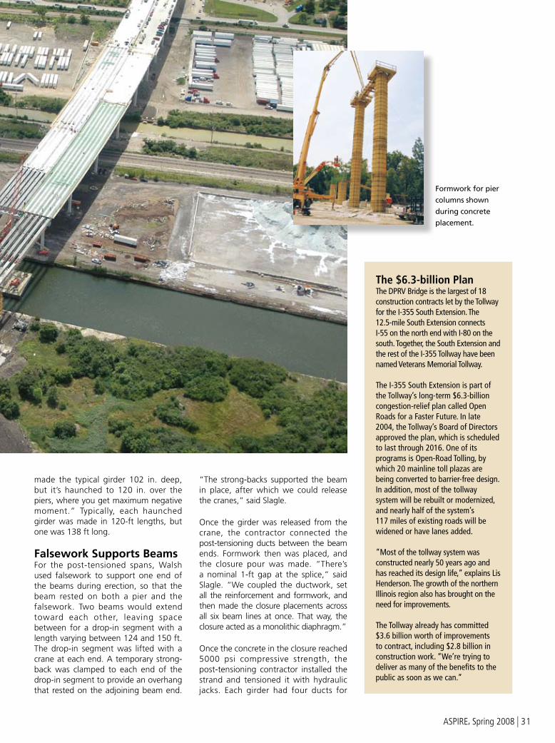
Formwork for pier
columns shown
during concrete
placement.
ASPIRE, Spring 2008 | 31
made the typical girder 102 in. deep, but it’s haunched to 120 in. over the piers, where you get maximum negative moment.” Typically, each haunched girder was made in 120-ft lengths, but one was 138 ft long.
Falsework Supports Beams For the post-tensioned spans, Walsh used falsework to support one end of the beams during erection, so that the beam rested on both a pier and the falsework. Two beams would extend toward each other, leaving space between for a drop-in segment with a length varying between 124 and 150 ft. The drop-in segment was lifted with a crane at each end. A temporary strong-back was clamped to each end of the drop-in segment to provide an overhang that rested on the adjoining beam end.
“The strong-backs supported the beam in place, after which we could release the cranes,” said Slagle.
Once the girder was released from the crane, the contractor connected the post-tensioning ducts between the beam ends. Formwork then was placed, and the closure pour was made. “There’s a nominal 1-ft gap at the splice,” said Slagle. “We coupled the ductwork, set all the reinforcement and formwork, and then made the closure placements across all six beam lines at once. That way, the closure acted as a monolithic diaphragm.”
Once the concrete in the closure reached 5000 psi compressive strength, the post-tensioning contractor installed the strand and tensioned it with hydraulic jacks. Each girder had four ducts for
The $6.3-billion Plan The DPRV Bridge is the largest of 18 construction contracts let by the Tollway for the I-355 South Extension. The 12.5-mile South Extension connects I-55 on the north end with I-80 on the south. Together, the South Extension and the rest of the I-355 Tollway have been named Veterans Memorial Tollway.
The I-355 South Extension is part of the Tollway’s long-term $6.3-billion congestion-relief plan called Open Roads for a Faster Future. In late 2004, the Tollway’s Board of Directors approved the plan, which is scheduled to last through 2016. One of its programs is Open-Road Tolling, by which 20 mainline toll plazas are being converted to barrier-free design. In addition, most of the tollway system will be rebuilt or modernized, and nearly half of the system’s 117 miles of existing roads will be widened or have lanes added.
“Most of the tollway system was constructed nearly 50 years ago and has reached its design life,” explains Lis Henderson. The growth of the northern Illinois region also has brought on the need for improvements.
The Tollway already has committed $3.6 billion worth of improvements to contract, including $2.8 billion in construction work. “We’re trying to deliver as many of the benefits to the public as soon as we can.”

Deck placement of unit 4 southbound
bridge. Deck was cast in a specific sequence
to avoid deck cracking over the piers.
Ongoing
construction of
the piers.
32 | ASPIRE, Spring 2008
the post-tensioning strand, explains Slagle. “Generally speaking, the ducts are arranged to be high over the piers and low at mid-span—points where the beam is in tension.”
New Forms CreatedThe $24-million contract for the precast, prestressed concrete girders produced the largest-ever contract for Prestress Engineering Corp. (PEC), which is Illinois’ largest precast concrete bridge supplier. To handle the order, the precaster built two in-ground casting beds in 5 months, bought three beam forms, doubled its workforce to 200 people, and purchased eight 10-axle trailers.
“We had to purchase seven additional acres,” says Terry Muntz, Vice President of Operations at PEC’s Blackstone, Illinois, plant. “Half of the land went for storage of product and the other half was used to build the two casting beds.” Each casting bed is 400 ft long by 20 ft wide by 10 ft deep.
The prairie winds blow strongly in Blackstone, so PEC built the beds in-ground to help keep the concrete warm during casting. The in-ground casting beds also permitted PEC to use shorter travel lifts. “This way we only had to lift the product the height of the beams before we could carry them,” says Muntz. “If we had a 10-ft-high form and a 10-ft-deep beam, we’d need to lift the beams to a point 20 ft above ground.”
Training the new employees was the biggest challenge, he adds. They also had to create a new safety plan to deal with the larger beams. The largest beams the company had previously cast were 72 in. deep, and the deepest beams at the DPRV Bridge were 120 in. deep.
Tollway officials take justifiable pride in their new bridge. “This bridge provides a great benefit to the driving public,” said Lis Henderson, a spokesperson for the Tollway.
For more information on this or other projects, visit www.aspirebridge.org.
Minimal Environmental Impact
The spliced girder design allowed the Tollway to use spans long enough to minimize the bridge’s impact on the wetlands through which it passes. The bridge and its construction had to meet environmental requirements set by the U.S. Army Corps of Engineers, the Illinois Department of Natural Resources, the Illinois EPA, and the U.S. Fish & Wildlife Service.
“This design allowed us to come in under the wetland acreages that we could impact on both a temporary and permanent basis,” says Paul Kovacs, Chief Engineer for the
Tollway. “We were able to affect only 8.77 acres during construction and only 3.87 acres permanently. We built 34 piers, and 16 of those are in wetland areas.”
Protected Species Believe it or not, a rare dragonfly helped influence the design of the DPRV Bridge. The area around the bridge serves as habitat for the Hine’s Emerald Dragonfly, which was listed as an endangered species in 1995.
“The Hine’s Emerald Dragonfly is one of the reasons the bridge was built as high
as it is,” says Kovacs. “We identified the dragonfly and studied its habitat. So we built the bridge 10 ft higher to keep cars out of the path of the dragonfly.” At its highest point, the bridge is 90 ft above grade.
The area is also inhabited by the Blanding’s Turtle, which needs to be protected. Colin Makin, the Tollway’s Deputy Program Manager for Bridges, said the turtles have been found and fitted with electronic locators. If a Blanding’s turtle roamed too close to the construction area, a group of environmentalists would pick up the turtle and relocate it.

How to do it in Precast…QA
How is the moment connection made?
All you need is an emulative detail, reconnect the concrete and rebar.
QA
How do you connect the rebar?
Use the… NMB Splice-Sleeve® System.
SPLICE SLEEVE NORTH AMERICA, INC.
WWW.SPLICESLEEVE.COM
cross-section
Edison Bridge, Fort Myers, Florida
Mill Street Bridge, Epping, New Hampshire
11003_SPLICE_.5bridge_win08.indd 1 11/30/07 10:51:14 AM
*Bridge-Brick is a term coined by Scott System to define the use of thin brick in bridge work.
10777 E. 45th Avenue • Denver, CO 80239Phone: 303-373-2500 • Fax: 303-373-2755
www.scottsystem.com
Durability
No Mortar
No Efflorescence
Specified by DOTs
Rim Snap™ System – Brick in Concrete
*
FORM
S
I-494/Valley Creek bridge in Woodbury, MN
S Y S T E Mthe art of concrete textures
Bridge-Brick CS2.indd 1 7/31/07 9:41:45 AM
ASPIRE, Spring 2008 | 33

Web | ASPIRE, Spring 2008
DES PLAINES RIVER VALLEY BRIDgE ON I-355 / LEMONT, ILLINOIS
Photos: Illinois State Toll Highway Authority.
PROJECT

ASPIRE, Spring 2008 | Web
DES PLAINES RIVER VALLEY BRIDgE ON I-355 / LEMONT, ILLINOIS
Photo: Illinois State Toll Highway Authority.
PROJECT

Web | ASPIRE, Spring 2008
DES PLAINES RIVER VALLEY BRIDgE ON I-355 / LEMONT, ILLINOIS
Photos: Illinois State Toll Highway Authority.
PROJECT