defect analysis workshop
TRANSCRIPT

Nordson Test and Inspection Defect Analysis Workshop John Travis

X-ray Inspection Criteria & Common Defect Analysis

WHAT IS THAT!!!!

4
Recognize & Identify Common Defects
Today's Mission
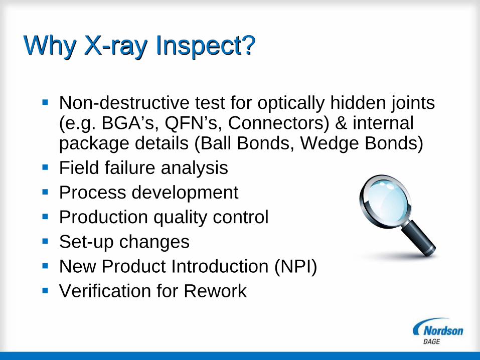
Why X-ray Inspect?
Non-destructive test for optically hidden joints (e.g. BGA’s, QFN’s, Connectors) & internal package details (Ball Bonds, Wedge Bonds)
Field failure analysis Process development Production quality control Set-up changes New Product Introduction (NPI) Verification for Rework

High magnification at Oblique Views Application Support Digital Processing Sub Micron/High Power High resolution (1.3 MP or more) Good separation of similar grey levels within the
x-ray image (65,000 Levels) Oblique views around point of analysis (Rotation) Ease of use
Suggested Requirements for X-ray Inspection

7
NO
RM
AL
VIEW
What are we seeing Here??
8
OB
LIQ
UE
VIEW
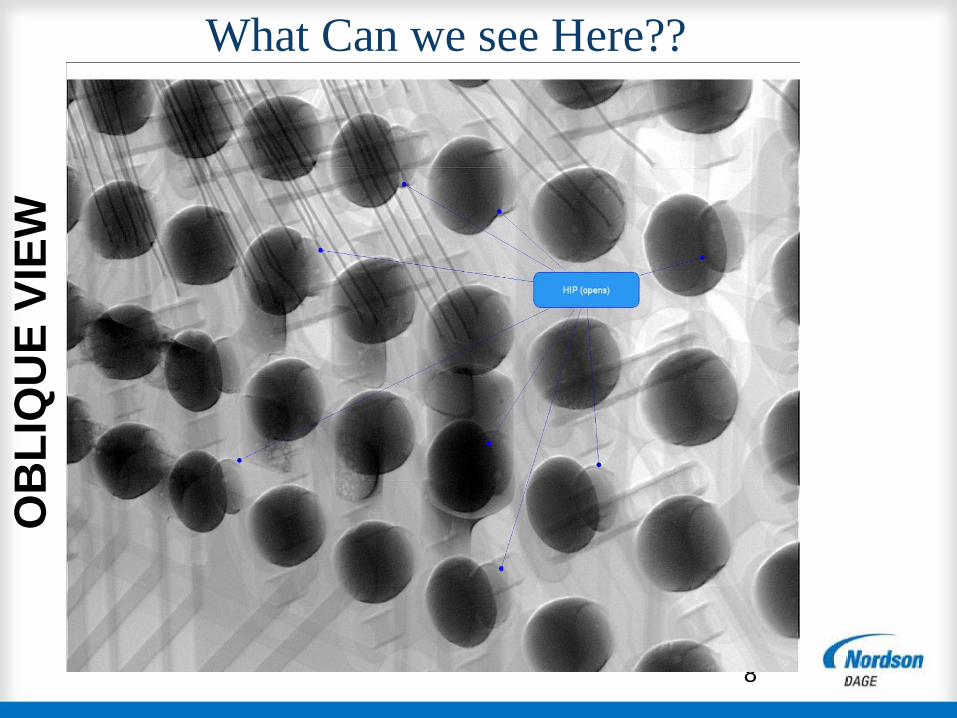
What Can we see Here??

9
PCB Pad
BGA
Ball
Solder Paste
Pad
PCB
2 x circles on the x-ray
image show BGA connection are OK
PCB
Solder Paste
BGA
Ball
If open connection, the circle on X-ray image will not be seen
X-Ray “OPEN Connection”
Inspection Logic

Proper BGA Wetting Principles
1. Solder ball is more dense than PCB pad
2. If proper wetting occurs the lighter density PCB pad shares its density with the ball.
3. That being the case, the pad will show up as a lighter color than the ball if a homogenous bond is created.
4. If proper wetting does not occur then the pad will carry it’s own density properties and will show up as a dark mass outside the perimeter of the BGA.

When the two masses do not share a common density, the PCB pad is exposed and an open solder joint is detected as indicated in the image on the left.
BGA Open

Strength of x-ray inspection is being able to look for opens, voiding, fractures and generally monitor production quality.
Also - able to prove to your customer that the reflow quality is good - BGAs are often forgiving of process variations - incl. Pb-free
Combat the frequently heard phrase from your customer - “The boards you sent me do not work! It must be how you soldered the BGA!”
Using XRAY for BGA Inspection

Common BGA Opens Cold Profile or Cold spots (visible solder-paste spheres) Hot Tears; caused by rapid cool down using lead free
paste Head in Pillow Exposed Pad on PCB……..Indicative of Profile not quite
hot enough to create an inter-metallic bond. Could also point to contaminated components.
Excessive Voiding Cracks or Fractures due to stress. Clogged Aperture on stencil Bridging

Head in Pillow


Copyright © Dage 2006
Transition from Hot to cold

BGA Voiding

Hot Tears or Fissures

21 | 00 Month 2009 | Confidential
Hot Tears or Fissures

Sample
Detector Rotates
X-ray Tube
principle – Limited Angle CT or PCT
2D images captured with detector at an angle
No sample size limitation as far as it fits in the X-Ray sample tray-No need to cut the sample
Small area of the sample imaged
Similar reconstruction method to full µCT – produces a CT model with 240 CT slices
No Limitations compared to full µCT
© NordsonDAGE 2012

23 | 00 Month 2009 | Confidential

Slices of BGA with Hot Tears
24 | 00 Month 2009 | Confidential

25 | | Confidential
a)
b)

Importance of Identifying Void Location
26 | 00 Month 2009 | Confidential

Solder voiding only reduced the reliability when the voids were located in the crack path

Types of Common Voids
28 | 00 Month 2009 | Confidential

Example of Champagne Voiding
29 | 00 Month 2009 | Confidential

Recommended BGA Inspection Procedure Always inspect at an Oblique Angle for Opens Check corners – shows lifting or Potato Chipping Work your way into the centre. This will Most likely to be the last point to reflow if any
substantial ∆T is present All terminations should be reasonably circular and
consistent in size Voiding, opens (non-reflow), HIP, Partial Wetting Inspect whole of BGA after rework – gives confidence in
the process

Increasing voiding Check fillets Solder balling
TARGET ACCEPTABLE DEFECT
Inspection Criteria Chip Components

Increasing voiding > 20% Check fillets Insufficient solder
TARGET ACCEPTABLE DEFECT
Inspection criteria (LGA)

Heel fillet voiding Joints reflowed Insufficient solder
TARGET ACCEPTABLE DEFECT
Inspection Criteria Gull Wings

Increasing voiding Joints reflowed Missing interfaces
TARGET ACCEPTABLE DEFECT
Inspection Criteria BGA
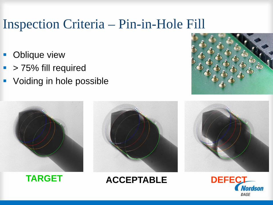
Inspection Criteria – Pin-in-Hole Fill
Oblique view > 75% fill required Voiding in hole possible
TARGET ACCEPTABLE DEFECT

LGA (QFN)


Acceptable QFN Solder
38 | 00 Month 2009 | Confidential

Insufficient Solder on QFN

Cracks & Breaks Copper tracks or in Solder Joints Die cracks: Fatigue from thermal cycling External stress (dropping) See an absence of material in x-ray image (from lower density) May need oblique view to see

Cracks & Breaks
Normal
(Top Down) View
Oblique View
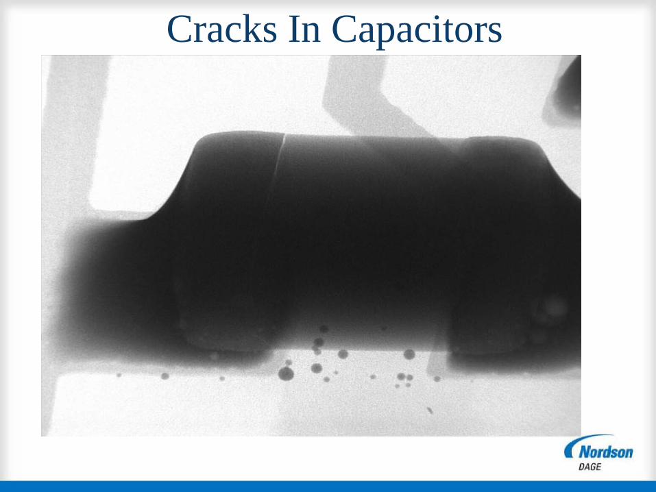
Cracks In Capacitors

Capacitor Cracks

Fillet Tearing in Lead-Free Joints


BGA Cracks

49 | 00 Month 2009 | Confidential
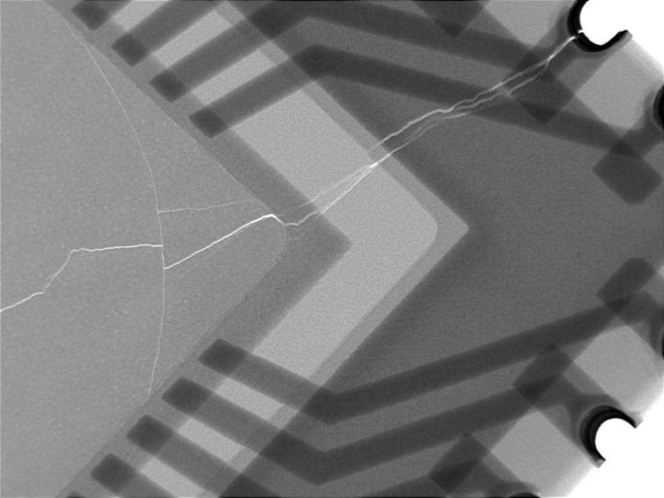
These devices were blowing up!
Dendrites

The standard micro sectioning methods could not find the problem

Dendrites between Pad and lead-frame on SOT 89 The bond wire is 20 microns diameter so the dendrites are only a few microns

Dendrites at High Magnification
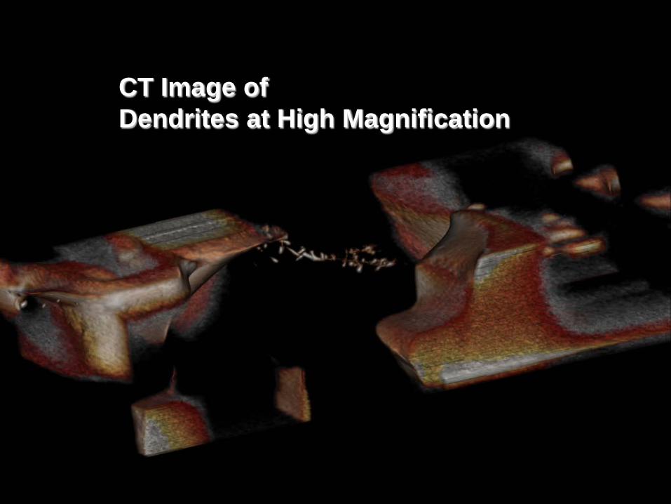
CT Image of Dendrites at High Magnification

Movie of Dendrites at High Magnification

55 | 00 Month 2009 | Confidential
Dendrites


57 | 00 Month 2009 | Confidential

58 | 00 Month 2009 | Confidential
Defective Traces

59 | 00 Month 2009 | Confidential

60 | 00 Month 2009 | Confidential

61 | 00 Month 2009 | Confidential

62 | 00 Month 2009 | Confidential

63 | 00 Month 2009 | Confidential
Through Hole Solder

64 | 00 Month 2009 | Confidential

www.yestechinc.com
Thank You!