defence works services - the national...
TRANSCRIPT
DEFENCE WORKS SERVICESMINISTRY OF DEFENCE
Defence Works Functional Standard
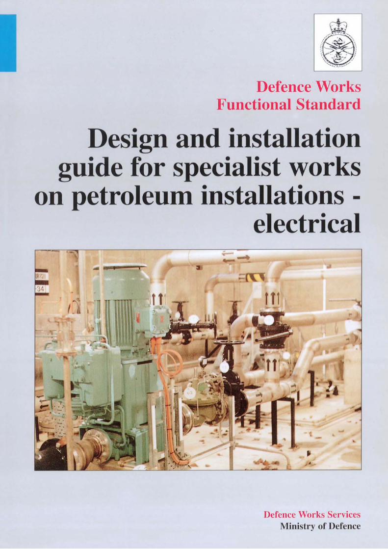
Design and installation guide forspecialist works on petroleuminstallations - electrical
JANUARY 1995COMPILED BY AIRFIELDS & BULK FUELS GROUPDEFENCE WORKS SERVICES
LONDON : HMSO

© Crown copyright 1995Applications for reproductions should be made to HMSOFirst published 1994
ISBN 0 1 1 772690 7
Amendments
Issue A, Rev 000 iii

Foreword
This document is for the use of Top Level Budget Holders (TLBHs) for applicationby the Project Sponsors, Property Managers (PROM), Establishment WorksConsultants (EWC), Works Services Managers (WSM) and other parties involved inthe design, selection and installation of electrical equipment within petroleumhazardous areas on the MOD estate.
The principal users of the document are expected to be EWC specifiers and WSMdesigners, installers and maintainers for works which fall within the PropertyServices remit; and Project Managers, designers and installers for projects.
The organisation of works on the MOD estate is determined by the value of theproject or task. Over a certain value work is conducted as a Project under the controlof a Project Sponsor, who directs the appointment of a Project Manager for allaspects of implementation. For work below the project value, the EWC, acting onbehalf of the PROM, briefs the WSM who acts as Project Manager for the works.When completed, the work is accepted by the Property Manager on the basis oftechnical acceptance by the EWC. Maintenance tasks are conducted by the WSM,and are subject to audit by the EWC.
The guidance given within this document is based upon British Standards,Health and Safety Guidance and Institute of Petroleum recommendations.Failure to implement the recommended practices given herein, could result insub-standard equipment and workmanship in petroleum hazardous areas. Theconsequence of sub-standard equipment and workmanship is a very highprobability of fire, explosion and possible loss of life.
This Defence Works Functional Standard supersedes the following Department ofEnvironment (DOE)/Property Services Agency (PSA) Electrical Designdocumentation, for petroleum hazardous installations :
DOE/PSA Mechanical and Electrical Engineering Guide (MEG), Volume 3,Section 24, (1990).
DOE/PSA Standard Specification (M&E) No.1 - Electrical Installations,(1985), Section 18.
This Functional Standard was prepared under the patronage of the DefencePetroleum Distribution Committee (DPOLDC) for application to electricalinstallations within hazardous areas at bulk petroleum installations on the MODestate.
Guidance is given on apparatus standards for electrical installations in hazardousareas. In addition, general electrical standards which apply to both hazardous andnon-hazardous areas, are cited in this Functional Standard. Examples are lightningprotection, earthing and BS 7671: Requirements for Electrical Installations.
This Functional Standard is not specifically directed to motor transport fillingstations, however the electrical principles involved in this document afford guidance.
Issue A, Rev 000iv
a.
b.
The design of motor transport filling stations should be in accordance with BritishStandards and Health and Safety Guidance documents. A DWS design guidancedocument to cater for MOD requirements at such installations is planned.
Amendments to this Functional Standard will be advised by DWS TechnicalBulletin, issued to PROM and TLBHs Works Staff. It is the responsibility of theuser to check with the PROM or Project Sponsor if amendments have been issued. Asheet is provided for recording amendments. In addition, there is a feedback sheet atAnnex B, for suggested changes or developments to the document.
Technical advice and assistance on MOD petroleum matters can be obtained fromDWS. Approaches may be through local DWS offices or directly to the petroleumTechnical Authority, (DWS TA):
Head of Bulk Petroleum InstallationsRoom 121Airfields and Bulk Fuels GroupPO Box 1734,SUTTON COLDFIELD,West Midlands,B75 7QB.
This DWS Functional Standard has been devised for use of the Crown and of itscontractors in the execution of contracts for the Crown and, subject to the UnfairContracts Tenns Act 1977, the Crown will not be liable in any way whatever(including but without limitation negligence on the part of the Crown its servants oragents) where the specification is used for other purposes.
Notwithstanding that this document sets out guidance for specialist works onpetroleum installations electrical, and is the MOD preferred solution, its use doesnot absolve a Project Manager from any responsibility for the design, neither doesits existence constrain him from using alternatives, provided such alternatives can bedemonstrated to provide a result of equal safety, quality and cost effectiveness.
Issue A, Rev 000
Abbreviations
AP (POL)APPET
AVCATAVGASAVTURBSBASEEFA
CENELECCSPDOEDPOLDCDWSEExExEWCFSIIGRPHSEIEE*IPIPJSPMODPCPPETPMPOLPROMPSAPVCSR&PLELUELTATLBH'sWSMXLPE
Authorised Person POL (current terminology)Authorised Person Petroleum (new terminology,to be introduced)Turbine Fuel, Aviation: High flash typeGasoline, Aviation: Grade 100/130Turbine Fuel, Aviation: Kerosine typeBritish StandardBritish Approval Service for Electrical Equipment inFlammable Atmospheres.European Committee for electrical standardisationChlorosulphonated polyethyleneDepartment of the EnvironmentDefence Petroleum Distribution CommitteeDefence Works ServicesEuropean Standard Certification MarkHealth and Safety Executive Certification MarkEstablishment Works ConsultantFuel System Icing InhibitorGlass Reinforced PlasticHealth and Safety ExecutiveInstitution of Electrical EngineersInstitute of PetroleumIngress ProtectionJoint Services PublicationMinistry of DefencePolychloroprenePetroleumProject ManagerPetroleum, Oil and LubricantProperty ManagerProperty Services AgencyPolyvinylchlorideSafety Rules and ProceduresLower Explosive LimitUpper Explosive LimitTechnical AuthorityTop Level Budget HoldersWorks Services ManagerCross Linked Polyethylene
Issue A, Rev 000vi
Contents
AMENDMENT SHEETABBREVIATIONSFOREWORDCONTENTS
GENERAL REQUIREMENTSINTRODUCTIONAIMDEFINITIONSREGULATIONSSTANDARDSEQUIPMENT CERTIFICATIONTRAININGDESIGN AND INSTALLATION CERTIFICATIONDRAWINGS, CALCULATIONS, MAINTENANCE ANDOPERATING INSTRUCTIONSMATERIALS
APPROACH TO THE SELECTION OF EQUIPMENTHAZARDOUS PROPERTIES OF PETROLEUMCLASSIFICATION OF HAZARDOUS AREASPROCEDURES FOR SELECTING ELECTRICALEQUIPMENT
MARKING OF ELECTRICAL EQUIPMENT
ELECTRICAL WIRING SYSTEMS WITHIN HAZARDOUSAREA
ELECTRICAL SUPPLIES AND WIRING SYSTEMS WITHINHAZARDOUS AREASWIRING SYSTEMS
EARTHING AND BONDINGGENERALELECTRICAL INSTALLATIONSLIGHTNING PROTECTIONEQUIPOTENTIAL BONDINGBONDING OF VEHICLES TO FIXED INSTALLATIONS
INSPECTION, TESTING AND MAINTENANCE OFELECTRICAL EQUIPMENT WITHIN HAZARDOUS AREAS
GENERALSAFE WORKING
ANNEX A - COMPLETION & INSPECTION CERTIFICATEANNEX B - CHANGE SUGGESTION FORM
Issue A, Rev 000 vii
1
2
3
4
5
1.11.21.31.41.51.61.71.81.9
1.10
2.12.22.3
2.4
3.1
3.2
4.14.24.34.44.5
5.15.2
1
13
21
23
27
2934
Specialist works on Section 1 - General requirementspetroleum installations- electrical
Section 1
General requirements
1.1 INTRODUCTION
DWS Functional Standard, Design and Installation Guide for Specialist Works onPetroleum Installations - Electrical, affords guidance and direction on the design,selection, and installation of electrical equipment within hazardous areas at fixedpetroleum installations on the MOD estate.
The Functional Standard guides the designer and installer of new facilities and themodifier and maintainer of existing facilities, in the precautions necessary to preventignition of an explosive atmosphere, caused by electrical equipment.
1.2 AIM
The aim of this Functional Standard is to:
Provide the details of design and installation standards for electricalequipment and associated works in fixed petroleum installations hazardousareas, within one document.
Give guidance in the selection and installation of equipment, once thehazardous area has been defined.
Provide a consistent approach in the selection of materials andworkmanship, which will ensure similar solutions being constructedthroughout the MOD estate.
Provide the designer and installer with guidance to engineer safe andeconomic solutions, whilst ensuring compliance with the requirements ofrelevant British Standards and other applicable Codes of Practice.
The document also assists the designer in the selection of materials, such as cables,which are used in non hazardous areas of petroleum installations.
1.2.1 Arrangement
The document is arranged in the following manner, to achieve the aim :
Section 1 includes the applicable standards, equipment certification,training of installation personnel, and the record information required forinstallations.
Issue A, Rev 000
a.
b.
c.
d.
a.
1
Specialist works on Section 1 - General requirementspetroleum installations- electrical
Section 2 comprises guidance on the approach to the selection of equipmentfor use in hazardous areas
Sections 3,4 and 5 cover the detailed matters of electrical supplies andsystems, earthing and bonding, and inspection and testing.
1.3 DEFINITIONS
The terms used within this standard shall be read as having the definitions givenbelow:
Approval (and words derived therefrom): Shall mean qualified approval in writingby the Project Manager (PM) or Works Service Manager (WSM), unless statedotherwise, for the design or commodities concerned, at the time of consideration.Any such approval shall be given without prejudice to the requirement that formalacceptance of the Works shall be subject to such performance, testing andcommissioning, as may be specified, and being to the satisfaction of the PM orWSM.
Apparatus Group: Certain electrical apparatus for use in hazardous areas isallocated a group depending on its suitability for use with specific gases.
Contractor: The company employed to carry out installation work on a site.
Earth: The conductive mass of Earth, whose electrical potential at any point isconventionally taken as zero.
Earth Electrode: A conductor or group of conductors in intimate contact with andproviding an electrical connection to Earth.
Establishment Works Consultant (EWC): The organisation responsible for theprovision of specialist examinations, surveying, scheduling, financial assessmentsand overseeing services in support of the PROM of the Establishment.
Equipotential Bonding: An electrical connection maintaining various exposed-conductive-parts and extraneous conductive parts at the same potential.
Explosive Atmosphere: A mixture with air, under atmospheric conditions, offlammable substances in the form of gas, vapour or mist in such proportions that itcan be exploded by excessive temperatures, arcs or sparks.
Equipment Certification: Equipment for use in Hazardous Areas is certified byone of a number of national testing authorities as meeting the requisite standard.This certification is arranged by the manufacturer of the equipment.
Flash Point: The minimum temperature at which a material gives off sufficientvapour to form an explosive atmosphere within the apparatus used for flash pointdetermination.
Hazardous Area: An area where flammable or explosive gas or vapour-air mixture(often referred to as explosive gas-air mixtures) is, or may be expected to be, present
Issue A, Rev 000
b.
c.
2
Specialist works on Section 1 - General requirementspetroleum installations- electrical
in quantities which require special precautions to be taken against the risk of ignition.
Ignition Temperature: The lowest temperature of a flammable gas or vapour atwhich ignition occurs.
Non-hazardous Area: An area in which an explosive atmosphere is not expectedto be present so that special precautions for the construction and use of the electricalequipment are not required.
Project Manager (PM): An official of the MOD or commercial representativeresponsible for the purpose of management and administration of the works coveredwithin this Functional Standard. For work within the remit of the WSM, the termPM shall be read as WSM.
Property Manager (PROM): An MOD official responsible for conducting theday-to-day property management business at the establishment.
Project Sponsor : The representative of the TLBH responsible for the delivery ofthe project through all stages.
Preferred: This indicates the course of action to be pursued when there is a choicebetween acceptable alternatives.
Technical Authority: Branch of DWS with responsibility for providing authorativetechnical works advice.
Temperature Class: One of six values of temperature allocated to electricalapparatus derived from a system of classification according to the maximum surfacetemperature of the apparatus.
Types of Protection: Measures applied in the construction of electrical apparatusto prevent the ignition of a surrounding explosive atmosphere by such apparatus.
Works: This covers design, procurement, manufacture, installation, and relevantmaintenance activities.
Works Services Manager (WSM): The organisation responsible to the PROM forplanning, organisation and managing operation, maintenance and repair of plant andfacilities, and the design and construction of new works up to a specific value on theMOD establishment for which it is appointed.
1.4 REGULATIONS
All work in and around petroleum hazardous areas must be carried out inaccordance with the applicable MOD safety rules and procedures for workon petroleum installations. The current procedures are DOE/PSA Mechanical andElectrical Engineering Guide, Volume 8, Sections 51 and 53, which will be replacedby MOD Safety Rules and Procedures.
When required by the MOD Safety Rules and Procedures, (SR&P), a coveringPermit to Work (Petroleum) must be obtained from the responsible AP PET prior tothe commencement of any work on or near a petroleum installation which either
Issue A, Rev 000 3
Specialist works on Section 1 - General requirementspetroleum installations- electrical
contains, or has previously contained, petroleum products. Notwithstanding thereceipt of a Permit to Work (Petroleum) in such cases, it shall be the responsibilityof the contractor to ensure that the requirements for safety specified in the MODSR&P are strictly complied with at all times.
The completed work, and all aspects of the execution thereof, shall comply with allrelevant latest enactments, statutory instruments, regulations and codes including thefollowing where applicable:
Factories Acts and Regulations made thereunder.
Health and Safety at Work Act and Regulations made thereunder.
Control of Pollution Act and Regulations made thereunder.
Petroleum (Consolidation) Act and Regulations made thereunder.
Home Office Model Code of Principles of Construction and LicensingConditions for Premises Licensed under the Petroleum (Consolidation) Act1928-Parts I and II.
Standards listed in clause 1.5.
HMSO Publication 'Standard Fire Precautions for Contractors Engaged onCrown Works'.
1.5 STANDARDS
The Works shall comply with the latest editions of appropriate standards including :
Issue A, Rev 000
a. British Standards:
BS308
BS 3429
BS 3939
BS 4533
BS 4568
BS 5000
BS 5000
BS 5070
Engineering drawing practice.
Specification for sizes of drawing sheets.
Graphical symbols for electric power, telecommunicationsand electronics diagrams.
Section 102.51, Specification for luminaries with type ofprotection N.
Parts 1 and 2: Steel conduit.
Part 16: Rotating electrical machines with type ofprotection N.
Part 17: Machines with flameproof enclosures.
Engineering diagram drawing practice.
a.
b.
c.
d.
e.
f.
g
4
Specialist works onpetroleum installations- electrical
Section 1 - General requirements
Code of practice for selection and maintenance of electricalapparatus for use in potentially explosive atmospheres(other than mining applications or explosive processingand manufacture).
Part 1: General recommendations.Part 2: Classification of hazardous areas.Part 3: Installation and maintenance requirements forelectrical apparatus with type of protection Flameproofenclosure.Part 4: Installation and maintenance requirements forelectrical apparatus with type protection 'i'. Intrinsicallysafe electrical apparatus and systems.Part 5: Installation and maintenance requirements forelectrical apparatus protected by pressurisation 'p' and bycontinuous dilution, for the pressurised room.Part 6: Installation and maintenance for electricalapparatus with type of protection Increased safety.Part 7: Installation and maintenance requirements forelectrical apparatus with type of protectionPart 8: Installation and maintenance requirements forelectrical apparatus with type of protection 's'. Specialprotection.
Specification for cables with thermosetting insulation forelectricity supply for rated voltages up to and including600/1000V and up to and including 1900/3300v.
Electrical apparatus for potentially explosive atmospheres.
Part 1: General requirements (EN 50014).Part 2: Oil immersion V (EN50015).Part 3: Pressurised apparatus "p" (EN50016).Part 4: Powder filling "q" (EN50017).Part 5: Flameproof enclosure "d" (EN50018).Part 6: Increased safety "e" (EN50019).Part 7: Intrinsic safety "i" (EN50020).Part 8: Encapsulation (EN50028).Part 9: Specification for intrinsically safe electrical systems"i" (EN50039).Note: EN numbers given in brackets are the Europeanstandard identical to the BS.
Code of practice for control of undesirable staticelectricity.
Part 1: Mechanical cable glands - specification for metallicglands.
Specification for mineral insulated copper sheathed cableswith copper conductors.
Issue A, Rev 000
BS 5345
BS 5467
BS 5501
BS 5958
BS 6121
BS 6207
5
Specialist works on Section 1 - General requirementspetroleum installations- electrical
Specification for PVC insulated cables for switchgear andcontrol gear.
Specification for PVC insulated cables for power supply.
Impregnated paper insulated lead/lead-alloy sheathedcables for rated voltages up to and including 3300V.
Code of practice for protection of structures againstlightning.
Guide to the prevention of inadvertent ignition offlammable atmospheres by radio frequency ignition.
Specification for electrical apparatus for explosiveatmospheres with type of protection
Cathodic protection.
Code of practice for earthing.
Requirements for electrical installations. Formerly the IEEwiring regulations sixteenth edition.
Specification for degrees of protection afforded byenclosures (IP code).
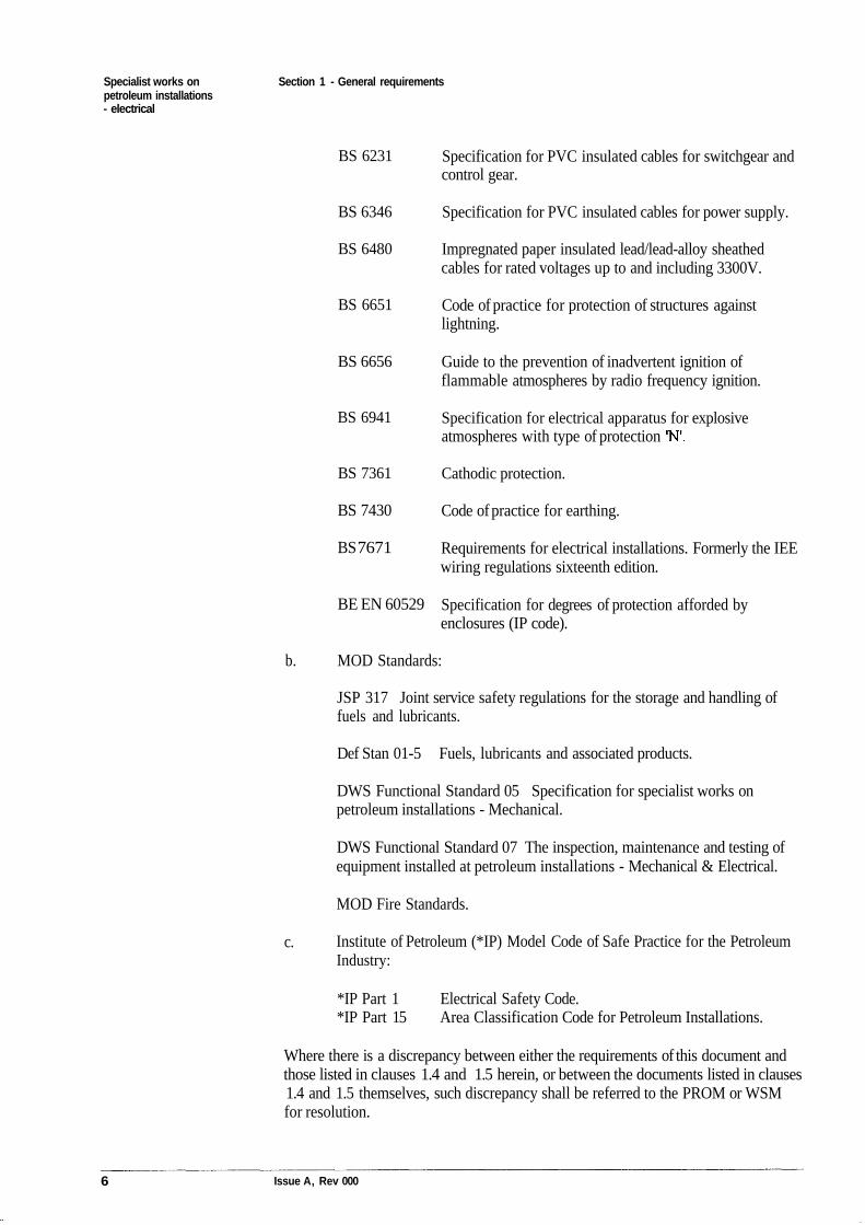
MOD Standards:
JSP 317 Joint service safety regulations for the storage and handling offuels and lubricants.
Def Stan 01-5 Fuels, lubricants and associated products.
DWS Functional Standard 05 Specification for specialist works onpetroleum installations - Mechanical.
DWS Functional Standard 07 The inspection, maintenance and testing ofequipment installed at petroleum installations - Mechanical & Electrical.
MOD Fire Standards.
Institute of Petroleum (*IP) Model Code of Safe Practice for the PetroleumIndustry:
*IP Part 1 Electrical Safety Code.*IP Part 15 Area Classification Code for Petroleum Installations.
Where there is a discrepancy between either the requirements of this document andthose listed in clauses 1.4 and 1.5 herein, or between the documents listed in clauses1.4 and 1.5 themselves, such discrepancy shall be referred to the PROM or WSMfor resolution.
Issue A, Rev 000
BS 6231
BS 6346
BS 6480
BS 6651
BS 6656
BS 6941
BS 7361
BS 7430
BS 7671
BE EN 60529
b.
c.
6
Specialist works on Section 1 - General requirementspetroleum installations- electrical
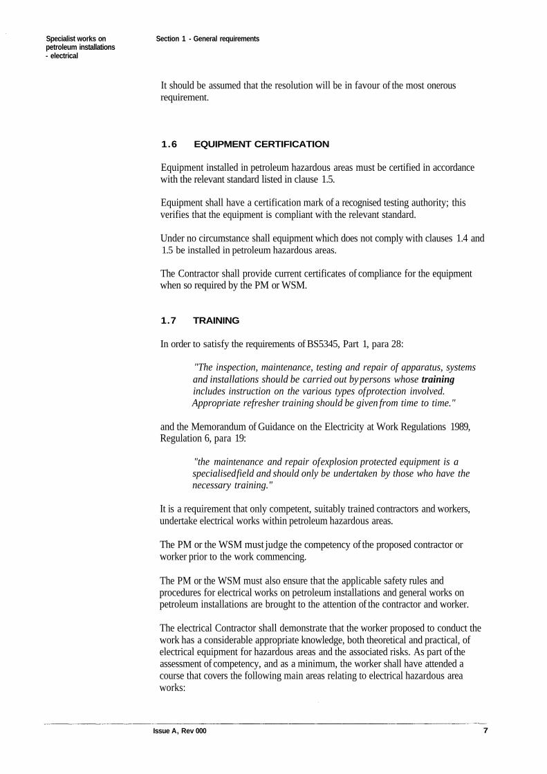
It should be assumed that the resolution will be in favour of the most onerousrequirement.
1.6 EQUIPMENT CERTIFICATION
Equipment installed in petroleum hazardous areas must be certified in accordancewith the relevant standard listed in clause 1.5.
Equipment shall have a certification mark of a recognised testing authority; thisverifies that the equipment is compliant with the relevant standard.
Under no circumstance shall equipment which does not comply with clauses 1.4 and1.5 be installed in petroleum hazardous areas.
The Contractor shall provide current certificates of compliance for the equipmentwhen so required by the PM or WSM.
1.7 TRAINING
In order to satisfy the requirements of BS5345, Part 1, para 28:
"The inspection, maintenance, testing and repair of apparatus, systemsand installations should be carried out by persons whose trainingincludes instruction on the various types of protection involved.Appropriate refresher training should be given from time to time."
and the Memorandum of Guidance on the Electricity at Work Regulations 1989,Regulation 6, para 19:
"the maintenance and repair of explosion protected equipment is aspecialised field and should only be undertaken by those who have thenecessary training."
It is a requirement that only competent, suitably trained contractors and workers,undertake electrical works within petroleum hazardous areas.
The PM or the WSM must judge the competency of the proposed contractor orworker prior to the work commencing.
The PM or the WSM must also ensure that the applicable safety rules andprocedures for electrical works on petroleum installations and general works onpetroleum installations are brought to the attention of the contractor and worker.
The electrical Contractor shall demonstrate that the worker proposed to conduct thework has a considerable appropriate knowledge, both theoretical and practical, ofelectrical equipment for hazardous areas and the associated risks. As part of theassessment of competency, and as a minimum, the worker shall have attended acourse that covers the following main areas relating to electrical hazardous areaworks:
Issue A, Rev 000 7
Specialist works on Section 1 - General requirementspetroleum installations- electrical
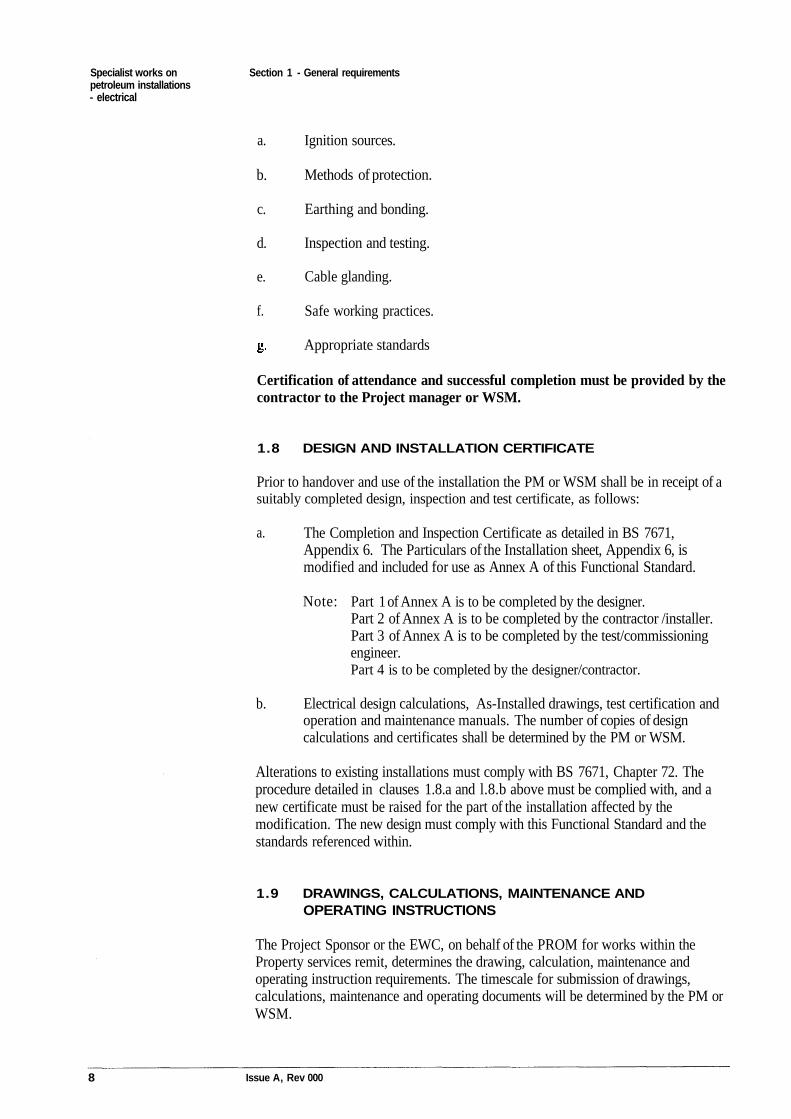
Ignition sources.
Methods of protection.
Earthing and bonding.
Inspection and testing.
Cable glanding.
Safe working practices.
Appropriate standards
Certification of attendance and successful completion must be provided by thecontractor to the Project manager or WSM.
1.8 DESIGN AND INSTALLATION CERTIFICATE
Prior to handover and use of the installation the PM or WSM shall be in receipt of asuitably completed design, inspection and test certificate, as follows:
The Completion and Inspection Certificate as detailed in BS 7671,Appendix 6. The Particulars of the Installation sheet, Appendix 6, ismodified and included for use as Annex A of this Functional Standard.
Part 1 of Annex A is to be completed by the designer.Part 2 of Annex A is to be completed by the contractor /installer.Part 3 of Annex A is to be completed by the test/commissioningengineer.Part 4 is to be completed by the designer/contractor.
Electrical design calculations, As-Installed drawings, test certification andoperation and maintenance manuals. The number of copies of designcalculations and certificates shall be determined by the PM or WSM.
Alterations to existing installations must comply with BS 7671, Chapter 72. Theprocedure detailed in clauses 1.8.a and l.8.b above must be complied with, and anew certificate must be raised for the part of the installation affected by themodification. The new design must comply with this Functional Standard and thestandards referenced within.
1.9 DRAWINGS, CALCULATIONS, MAINTENANCE ANDOPERATING INSTRUCTIONS
The Project Sponsor or the EWC, on behalf of the PROM for works within theProperty services remit, determines the drawing, calculation, maintenance andoperating instruction requirements. The timescale for submission of drawings,calculations, maintenance and operating documents will be determined by the PM orWSM.
Issue A, Rev 000
a.
b.
Note:
a.
b.
c.
d.
e.
f.
8
Specialist works on Section 1 - General requirementspetroleum installations- electrical
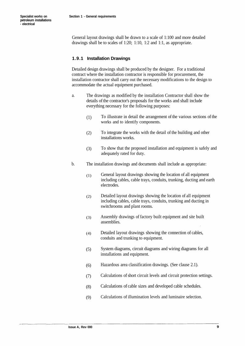
General layout drawings shall be drawn to a scale of 1:100 and more detaileddrawings shall be to scales of 1:20; 1:10, 1:2 and 1:1, as appropriate.
1.9.1 Installation Drawings
Detailed design drawings shall be produced by the designer. For a traditionalcontract where the installation contractor is responsible for procurement, theinstallation contractor shall carry out the necessary modifications to the design toaccommodate the actual equipment purchased.
The drawings as modified by the installation Contractor shall show thedetails of the contractor's proposals for the works and shall includeeverything necessary for the following purposes:
To illustrate in detail the arrangement of the various sections of theworks and to identify components.
To integrate the works with the detail of the building and otherinstallations works.
To show that the proposed installation and equipment is safely andadequately rated for duty.
The installation drawings and documents shall include as appropriate:
General layout drawings showing the location of all equipmentincluding cables, cable trays, conduits, trunking, ducting and earthelectrodes.
Detailed layout drawings showing the location of all equipmentincluding cables, cable trays, conduits, trunking and ducting inswitchrooms and plant rooms.
Assembly drawings of factory built equipment and site builtassemblies.
Detailed layout drawings showing the connection of cables,conduits and trunking to equipment.
System diagrams, circuit diagrams and wiring diagrams for allinstallations and equipment.
Hazardous area classification drawings. (See clause 2.1).
Calculations of short circuit levels and circuit protection settings.
Calculations of cable sizes and developed cable schedules.
Calculations of illumination levels and luminaire selection.
Issue A, Rev 000 9
(1)
(2)
(3)
(4)
(5)
(6)
(7)
(8)
(9)
b.
(1)
(2)
(3)
a.
Specialist works on Section 1 - General requirementspetroleum installations- electrical
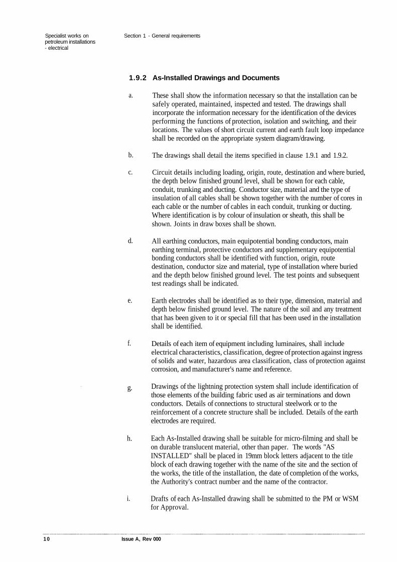
1.9.2 As-Installed Drawings and Documents
These shall show the information necessary so that the installation can besafely operated, maintained, inspected and tested. The drawings shallincorporate the information necessary for the identification of the devicesperforming the functions of protection, isolation and switching, and theirlocations. The values of short circuit current and earth fault loop impedanceshall be recorded on the appropriate system diagram/drawing.
The drawings shall detail the items specified in clause 1.9.1 and 1.9.2.
Circuit details including loading, origin, route, destination and where buried,the depth below finished ground level, shall be shown for each cable,conduit, trunking and ducting. Conductor size, material and the type ofinsulation of all cables shall be shown together with the number of cores ineach cable or the number of cables in each conduit, trunking or ducting.Where identification is by colour of insulation or sheath, this shall beshown. Joints in draw boxes shall be shown.
All earthing conductors, main equipotential bonding conductors, mainearthing terminal, protective conductors and supplementary equipotentialbonding conductors shall be identified with function, origin, routedestination, conductor size and material, type of installation where buriedand the depth below finished ground level. The test points and subsequenttest readings shall be indicated.
Earth electrodes shall be identified as to their type, dimension, material anddepth below finished ground level. The nature of the soil and any treatmentthat has been given to it or special fill that has been used in the installationshall be identified.
Details of each item of equipment including luminaires, shall includeelectrical characteristics, classification, degree of protection against ingressof solids and water, hazardous area classification, class of protection againstcorrosion, and manufacturer's name and reference.
Drawings of the lightning protection system shall include identification ofthose elements of the building fabric used as air terminations and downconductors. Details of connections to structural steelwork or to thereinforcement of a concrete structure shall be included. Details of the earthelectrodes are required.
Each As-Installed drawing shall be suitable for micro-filming and shall beon durable translucent material, other than paper. The words "ASINSTALLED" shall be placed in 19mm block letters adjacent to the titleblock of each drawing together with the name of the site and the section ofthe works, the title of the installation, the date of completion of the works,the Authority's contract number and the name of the contractor.
Drafts of each As-Installed drawing shall be submitted to the PM or WSMfor Approval.
1 0 Issue A, Rev 000
a.
b.
c.
d.
e.
f.
g.
h.
i.
Specialist works on Section 1 - General requirementspetroleum installations- electrical
The number and format of final As-Installed drawings will be advised bythe PM or WSM.
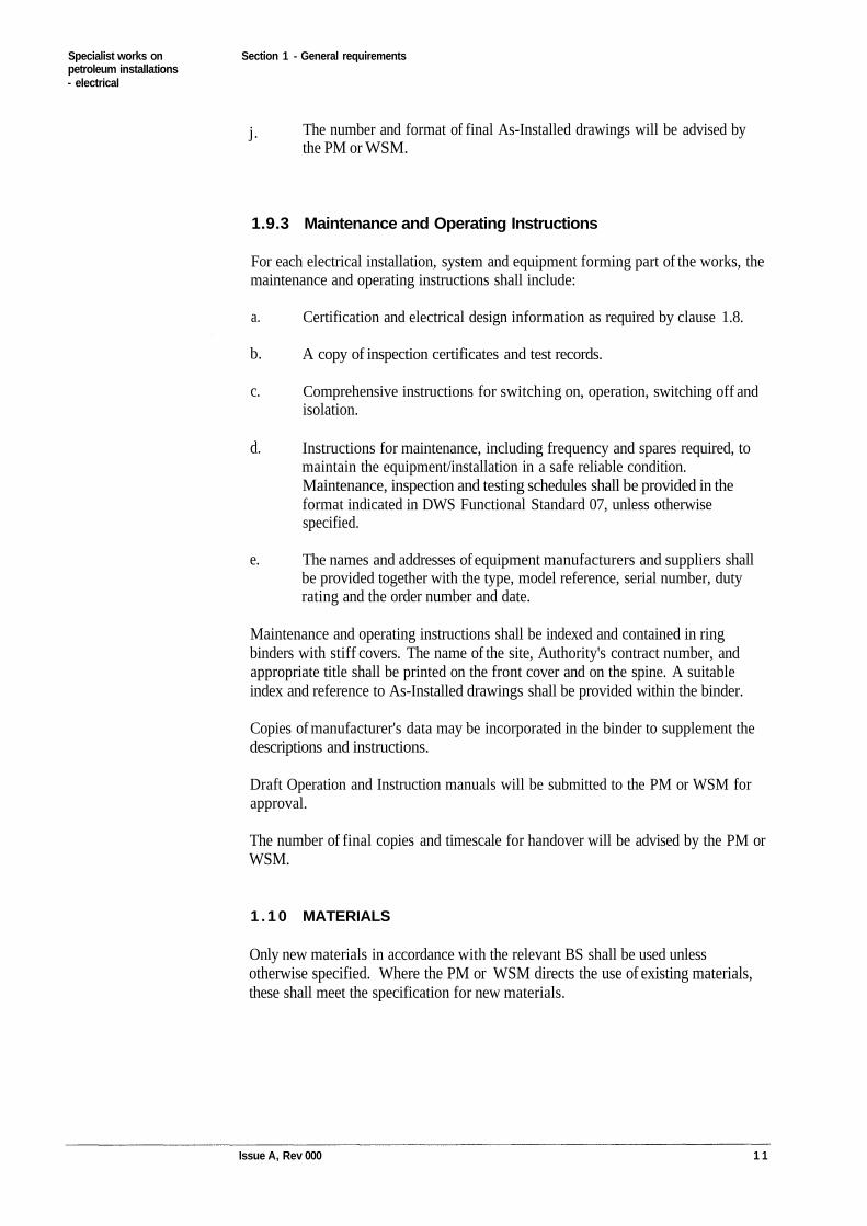
1.9.3 Maintenance and Operating Instructions
For each electrical installation, system and equipment forming part of the works, themaintenance and operating instructions shall include:
Certification and electrical design information as required by clause 1.8.
A copy of inspection certificates and test records.
Comprehensive instructions for switching on, operation, switching off andisolation.
Instructions for maintenance, including frequency and spares required, tomaintain the equipment/installation in a safe reliable condition.Maintenance, inspection and testing schedules shall be provided in theformat indicated in DWS Functional Standard 07, unless otherwisespecified.
The names and addresses of equipment manufacturers and suppliers shallbe provided together with the type, model reference, serial number, dutyrating and the order number and date.
Maintenance and operating instructions shall be indexed and contained in ringbinders with stiff covers. The name of the site, Authority's contract number, andappropriate title shall be printed on the front cover and on the spine. A suitableindex and reference to As-Installed drawings shall be provided within the binder.
Copies of manufacturer's data may be incorporated in the binder to supplement thedescriptions and instructions.
Draft Operation and Instruction manuals will be submitted to the PM or WSM forapproval.
The number of final copies and timescale for handover will be advised by the PM orWSM.
1 . 1 0 MATERIALS
Only new materials in accordance with the relevant BS shall be used unlessotherwise specified. Where the PM or WSM directs the use of existing materials,these shall meet the specification for new materials.
Issue A, Rev 000 1 1
a.
b.
c.
d.
e.
j.
Specialist works on Section 2 - Background for the selection of equipmentpetroleum installations- electrical
Section 2
Background for the selection of equipment
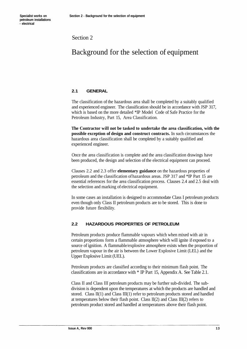
2.1 GENERAL
The classification of the hazardous area shall be completed by a suitably qualifiedand experienced engineer. The classification should be in accordance with JSP 317,which is based on the more detailed *IP Model Code of Safe Practice for thePetroleum Industry, Part 15, Area Classification.
The Contractor will not be tasked to undertake the area classification, with thepossible exception of design and construct contracts. In such circumstances thehazardous area classification shall be completed by a suitably qualified andexperienced engineer.
Once the area classification is complete and the area classification drawings havebeen produced, the design and selection of the electrical equipment can proceed.
Clauses 2.2 and 2.3 offer elementary guidance on the hazardous properties ofpetroleum and the classification of hazardous areas. JSP 317 and *IP Part 15 areessential references for the area classification process. Clauses 2.4 and 2.5 deal withthe selection and marking of electrical equipment.
In some cases an installation is designed to accommodate Class I petroleum productseven though only Class II petroleum products are to be stored. This is done toprovide future flexibility.
2.2 HAZARDOUS PROPERTIES OF PETROLEUM
Petroleum products produce flammable vapours which when mixed with air incertain proportions form a flammable atmosphere which will ignite if exposed to asource of ignition. A flammable/explosive atmosphere exists when the proportion ofpetroleum vapour in the air is between the Lower Explosive Limit (LEL) and theUpper Explosive Limit (UEL).
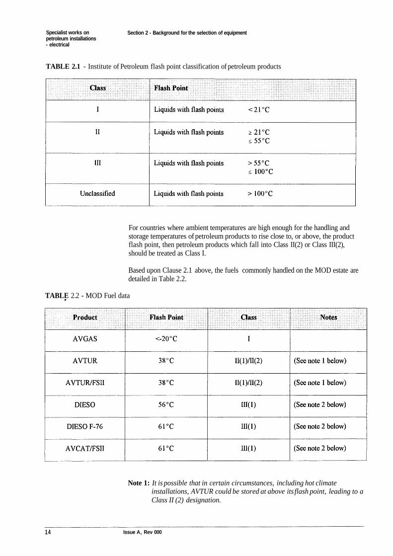
Petroleum products are classified according to their minimum flash point. Theclassifications are in accordance with * IP Part 15, Appendix A. See Table 2.1.
Class II and Class III petroleum products may be further sub-divided. The sub-division is dependent upon the temperatures at which the products are handled andstored. Class II(1) and Class III(1) refer to petroleum products stored and handledat temperatures below their flash point. Class II(2) and Class III(2) refers topetroleum product stored and handled at temperatures above their flash point.
Issue A, Rev 000 13
Specialist works onpetroleum installations- electrical
Section 2 - Background for the selection of equipment
TABLE 2.1 - Institute of Petroleum flash point classification of petroleum products
For countries where ambient temperatures are high enough for the handling andstorage temperatures of petroleum products to rise close to, or above, the productflash point, then petroleum products which fall into Class II(2) or Class III(2),should be treated as Class I.
Based upon Clause 2.1 above, the fuels commonly handled on the MOD estate aredetailed in Table 2.2.
TABLE 2.2 - MOD Fuel data
Note 1: It is possible that in certain circumstances, including hot climateinstallations, AVTUR could be stored at above its flash point, leading to aClass II (2) designation.
14 Issue A, Rev 000

Specialist works onpetroleum installations- electrical
Section 2 - Background for the selection of equipment
Note 2: Although Class III products are not likely to reach their flashpoints innormal circumstances and thus do not give rise to a flammable vapour,they are treated as hazardous products in accordance with IP Part 15,Clause 2.12.3 in that the inside of the tank and an area around the ventare classified as hazardous zones.
Specific guidance on petroleum characteristics are given in MOD, Defence Standard01-5/Issue 10 (November 1993); Fuels, Lubricants and Associated Products.Further information is available from the DWS TA.
2.3 CLASSIFICATION OF HAZARDOUS AREAS
Hazardous area classification zones are defined in BS5345 and presented in Table2.3.
TABLE 2.3 - Zone definitions (BS 5345)
Zone 0
Zone 1
Zone 2
Zone in which an explosive atmosphere is continuously present, or present for longperiods
Zone in which an explosive atmosphere is likely to occur under normal operation.
Zone in which an explosive atmosphere is not likely to occur in normal operation, andif it occurs will only exist for a short time.
2.4 PROCEDURES FOR SELECTING ELECTRICAL EQUIPMENT
The selection of electrical equipment for use in petroleum hazardous zones isdependent upon the four following criteria:
2.4.1 The Selection of Equipment Suitable for the ParticularHazardous Zone
BS 5345 determines that there are nine accepted types of protection for electricalapparatus. The relationships between the type of protection and zone are given inTable 2.4.
Issue A, Rev 000 15
Specialist works onpetroleum installations- electrical
Section 2 - Background for the selection of equipment
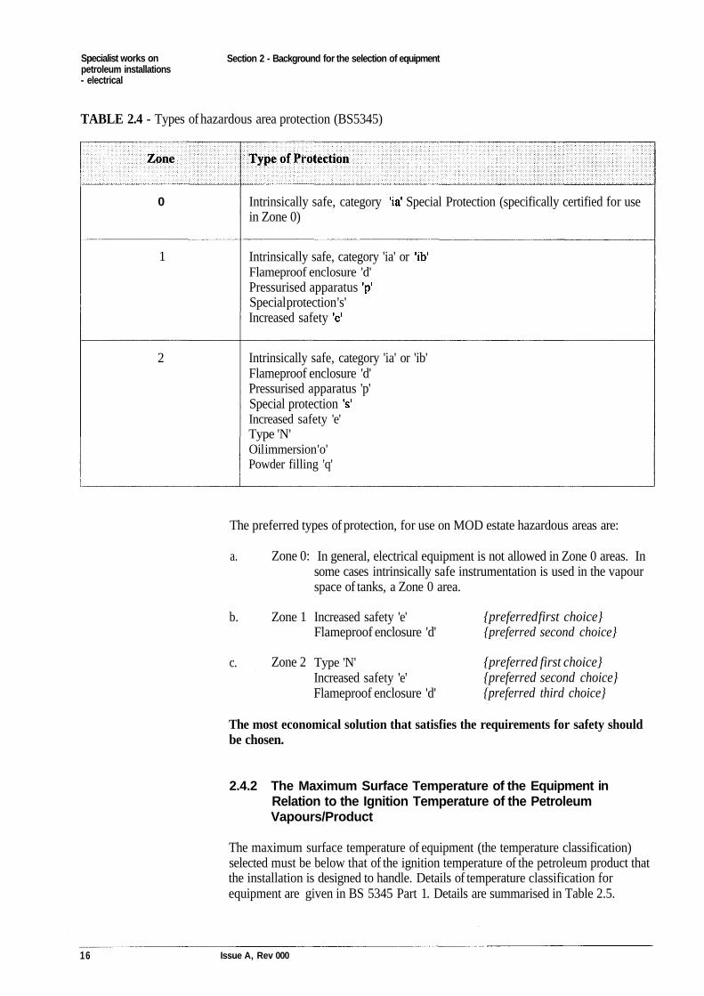
TABLE 2.4 - Types of hazardous area protection (BS5345)
Intrinsically safe, category Special Protection (specifically certified for usein Zone 0)
Intrinsically safe, category 'ia' orFlameproof enclosure 'd'Pressurised apparatusSpecial protection 's'Increased safety
Intrinsically safe, category 'ia' or 'ib'Flameproof enclosure 'd'Pressurised apparatus 'p'Special protectionIncreased safety 'e'Type 'N'Oil immersion 'o'Powder filling 'q'
The preferred types of protection, for use on MOD estate hazardous areas are:
a.
b.
c.
In general, electrical equipment is not allowed in Zone 0 areas. Insome cases intrinsically safe instrumentation is used in the vapourspace of tanks, a Zone 0 area.
Increased safety 'e'Flameproof enclosure 'd'
Type 'N'Increased safety 'e'Flameproof enclosure 'd'
{preferred first choice}{preferred second choice}
{preferred first choice}{preferred second choice}{preferred third choice}
The most economical solution that satisfies the requirements for safety shouldbe chosen.
2.4.2 The Maximum Surface Temperature of the Equipment inRelation to the Ignition Temperature of the PetroleumVapours/Product
The maximum surface temperature of equipment (the temperature classification)selected must be below that of the ignition temperature of the petroleum product thatthe installation is designed to handle. Details of temperature classification forequipment are given in BS 5345 Part 1. Details are summarised in Table 2.5.
16 Issue A, Rev 000
Zone 0:
Zone 1
Zone 2
0
1
2
Specialist works onpetroleum installations- electrical
Section 2 - Background for the selection of equipment
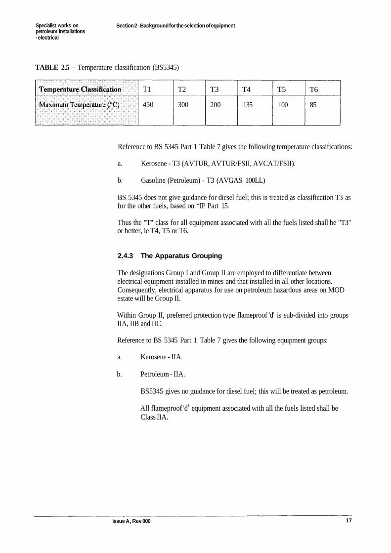
TABLE 2.5 - Temperature classification (BS5345)
T1
450
T2
300
T3
200
T4
135
T5
100
T6
85
Reference to BS 5345 Part 1 Table 7 gives the following temperature classifications:
Kerosene - T3 (AVTUR, AVTUR/FSII, AVCAT/FSII).
Gasoline (Petroleum) - T3 (AVGAS 100LL)
BS 5345 does not give guidance for diesel fuel; this is treated as classification T3 asfor the other fuels, based on *IP Part 15.
Thus the "T" class for all equipment associated with all the fuels listed shall be "T3"or better, ie T4, T5 or T6.
2.4.3 The Apparatus Grouping
The designations Group I and Group II are employed to differentiate betweenelectrical equipment installed in mines and that installed in all other locations.Consequently, electrical apparatus for use on petroleum hazardous areas on MODestate will be Group II.
Within Group II, preferred protection type flameproof 'd' is sub-divided into groupsIIA, IIB and IIC.
Reference to BS 5345 Part 1 Table 7 gives the following equipment groups:
Kerosene - IIA.
Petroleum - IIA.
BS5345 gives no guidance for diesel fuel; this will be treated as petroleum.
All flameproof 'd1 equipment associated with all the fuels listed shall beClass IIA.
Issue A, Rev 000 17
a.
b.
a.
b.
Specialist works onpetroleum installations- electrical
Section 2 - Background for the selection of equipment
2.4.4 The Environmental Conditions at the Installation
Electrical equipment installed within hazardous areas shall be suitable for theenvironmental conditions to which it is exposed. This will include protectionagainst:
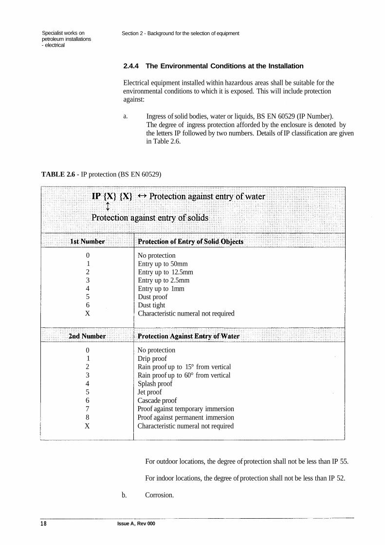
Ingress of solid bodies, water or liquids, BS EN 60529 (IP Number).The degree of ingress protection afforded by the enclosure is denoted bythe letters IP followed by two numbers. Details of IP classification are givenin Table 2.6.
TABLE 2.6 - IP protection (BS EN 60529)
0123456X
No protectionEntry up to 50mmEntry up to 12.5mmEntry up to 2.5mmEntry up to 1mmDust proofDust tightCharacteristic numeral not required
012345678X
No protectionDrip proofRain proof up to 15° from verticalRain proof up to 60° from verticalSplash proofJet proofCascade proofProof against temporary immersionProof against permanent immersionCharacteristic numeral not required
For outdoor locations, the degree of protection shall not be less than IP 55.
For indoor locations, the degree of protection shall not be less than IP 52.
Corrosion.
1 8 Issue A, Rev 000
b.
a.

Specialist works on Section 2 - Background for the selection of equipmentpetroleum installations- electrical
Effects of exposure to the petroleum product.
Effects of heat from adjacent plant.
2.5 MARKING OF ELECTRICAL EQUIPMENT
The explosion-protection markings of electrical apparatus permits visualconfirmation of the correct selection of suitable equipment for the hazardous zone.
The markings are defined in the relevant BS and include the following details:
The name of the manufacturer or his registered trade mark.
The manufacturer's type identification.
The symbol Ex or EEx, which indicates that the electrical apparatuscorresponds to one or more of the types of protection as required by theappropriate standards. (See clause 2.5.g. below).
The symbol for the type of protection used, either 'e' or 'N'.
The symbol of the group of electrical apparatus, for protection type 'd',either IIA, IIB or IIC.
The symbol indicating the temperature class.
The number of the certificate and name or mark of the certifying authority.
Note: If the type of protection complies with a British Standard, whichmirrors a European Standard, for example BS5501 part I, and equivalentBS EN 50014, then the prefix to the type of protection code becomes'EEx'.The Registered mark for the British Approval Service for ElectricalEquipment in Flammable Atmospheres (BASEEFA) are the letters 'Ex'
are located within a crown. Similarly equipment certified by SiraCertification Service would be marked with 'SCS'.
Any other particular information, for example, IP protection or electricalrating.
Issue A, Rev 000 19
a.
b.
c.
d.
e.
f.
g.
h.
c.
d.
Specialist works on Section 3 - Electrical supplies and wiring systems within hazardous areaspetroleum installations- electrical
Section 3
Electrical supplies and wiring systems withinhazardous areas
3.1 ELECTRICAL SUPPLIES
The electrical supply to a petroleum hazardous area shall be via underground cablesexcept where cables necessarily have to exit the ground to reach above-groundequipment. When the installation is supplied via overhead circuit this shall terminateoutside of the hazardous area and be routed via underground cable to theinstallation. Overhead conductors are not permitted within the hazardous area.Underground cables shall be protected against mechanical and environmentaldamage. LV cables shall be installed to a minimum depth of 500mm in open groundand under footpaths and 800mm under roadways unless otherwise specified by thePM. Warning tape shall be placed above each cable route mat is laid directly in theground, at a depth of 300mm below finished ground level. Where ducting entershazardous areas the cable ducts shall be sealed with a suitable petroleum resistantmaterial to prevent the ingress of hazardous vapour or product.
The petroleum installation electrical supply shall generally be 240V 50Hz, single-phase and neutral or 415/140V, 50Hz, 3 phase and neutral with the neutral solidlyearthed at source.
The electrical supply shall be TN-S or TT as defined in BS 7671.
TN-C, TN-C-S and IT systems are not acceptable in classified hazardousareas.
When the petroleum installation is fed from a dedicated substation or a feeder pillarfeeding other installations, the new installation shall be constructed sufficiently faraway from the electrical supply so that the electrical supply equipment is outside ofthe hazardous area.
As a matter of good practice and economics, whenever possible, the electricalequipment should be located outside of the classified hazardous area.
Standby power supplies, when provided, shall be located outside the hazardous area.The standby power supply shall be provided with suitable changeover and isolationfacilities.
Issue A, Rev 000 21
Specialist works on Section 3 - Electrical supplies and wiring systems within hazardous areaspetroleum installations- electrical
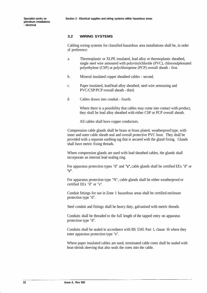
3.2 WIRING SYSTEMS
Cabling wiring systems for classified hazardous area installations shall be, in orderof preference:
Thermoplastic or XLPE insulated, lead alloy or thermoplastic sheathed,single steel wire armoured with polyvinylchloride (PVC), chlorosulphonatedpolyethylene (CSP) or polychloroprene (PCP) overall sheath - first.
Mineral insulated copper sheathed cables - second.
Paper insulated, lead/lead alloy sheathed, steel wire armouring andPVC/CSP/PCP overall sheath - third.
Cables drawn into conduit - fourth.
Where there is a possibility that cables may come into contact with product,they shall be lead alloy sheathed with either CSP or PCP overall sheath.
All cables shall have copper conductors.
Compression cable glands shall be brass or brass plated, weatherproof type, withinner and outer cable sheath seal and overall protective PVC boot. They shall beprovided with a separate earthing tag that is secured with the gland fixing. Glandsshall have metric fixing threads.
Where compression glands are used with lead sheathed cables, the glands shallincorporate an internal lead sealing ring.
For apparatus protection types "d" and cable glands shall be certified EEx "d" or
For apparatus protection type "N", cable glands shall be either weatherproof orcertified EEx "d" or "e".
Conduit fittings for use in Zone 1 hazardous areas shall be certified enclosureprotection type "d".
Steel conduit and fittings shall be heavy duty, galvanised with metric threads.
Conduits shall be threaded to the full length of the tapped entry on apparatusprotection type "d".
Conduits shall be sealed in accordance with BS 5345 Part 1, clause 16 where theyenter apparatus protection type "e".
Where paper insulated cables are used, terminated cable cores shall be sealed withheat-shrink sleeving that also seals the cores into the cable.
22 Issue A, Rev 000
a.
b.
c.
d.
Specialist works on Section 4 - Earthing and bondingpetroleum installations- electrical
Section 4
Earthing and bonding
4.1 GENERAL
Flammable atmospheres found in the vicinity of petroleum installations necessitatespecial earthing and bonding procedures which by correct design and installationmust provide adequate protection against fire and explosion. The employment ofearthing and bonding can generally be sub-divided into three categories, thoseassociated with the:
Electrical installation.
Protection against lightning.
Equipotential bonding of structures, storage tanks, plant, pipelines andother non-electrical metallic parts.
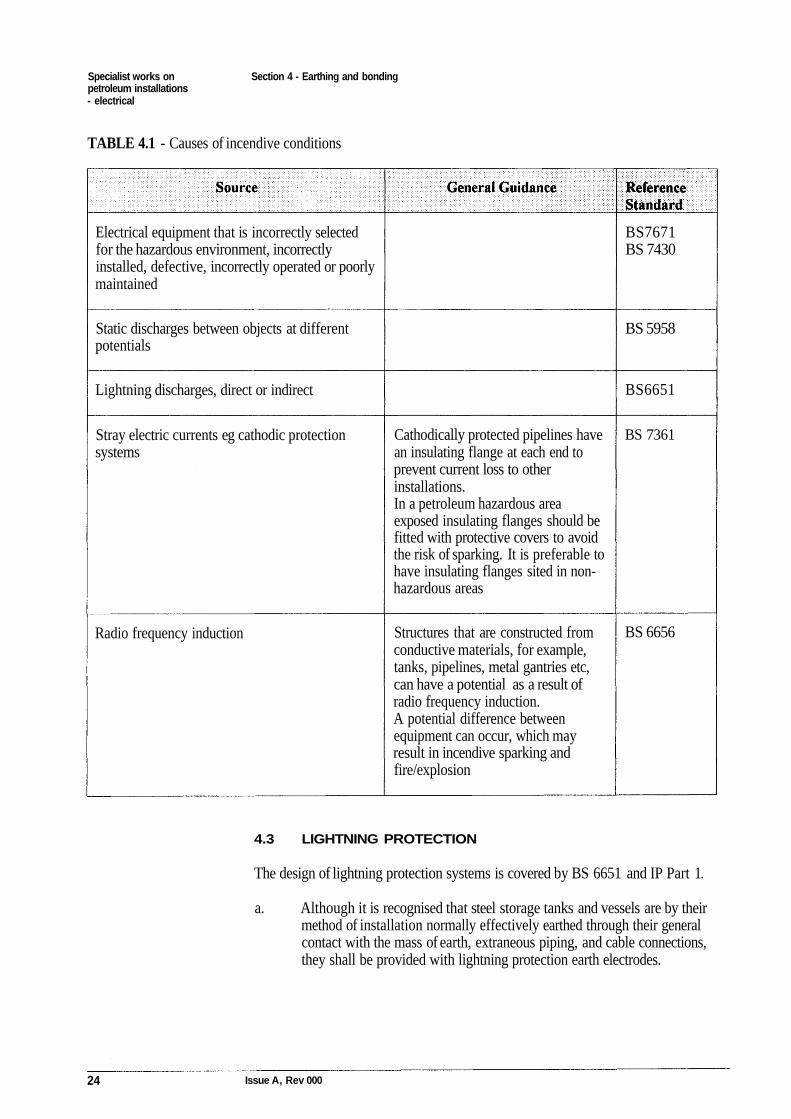
Details of potential causes of incendive conditions and the relevant precautionaryguidance documentation are given in the Table 4.1.
4.2 ELECTRICAL INSTALLATION
The design of the electrical system and installation shall be in accordance with BS7671, BS 7430 and IP Part 1.
As noted in clause 3.1 above, the electrical distribution system shall be TN-S. Thisrequires a protective conductor(s) to connect the main source earth to the variousitems of electrical equipment.
For all wiring systems, a separate dedicated protective conductor shall be providedas part of the wiring system and shall comprise:
Copper conductor incorporated in an armoured flexible cable.
Separately insulated copper conductor.
The protective conductors shall be sized in accordance with BS 7671 Chapter 54.
Issue A, Rev 000 23
a.
b.
c.
a.
b.
Specialist works onpetroleum installations- electrical
Section 4 - Earthing and bonding
TABLE 4.1 - Causes of incendive conditions
Electrical equipment that is incorrectly selectedfor the hazardous environment, incorrectlyinstalled, defective, incorrectly operated or poorlymaintained
BS7671BS 7430
Static discharges between objects at differentpotentials
BS 5958
Lightning discharges, direct or indirect BS6651
Stray electric currents eg cathodic protectionsystems
Cathodically protected pipelines havean insulating flange at each end toprevent current loss to otherinstallations.In a petroleum hazardous areaexposed insulating flanges should befitted with protective covers to avoidthe risk of sparking. It is preferable tohave insulating flanges sited in non-hazardous areas
BS 7361
Radio frequency induction Structures that are constructed fromconductive materials, for example,tanks, pipelines, metal gantries etc,can have a potential as a result ofradio frequency induction.A potential difference betweenequipment can occur, which mayresult in incendive sparking andfire/explosion
BS 6656
4.3 LIGHTNING PROTECTION
The design of lightning protection systems is covered by BS 6651 and IP Part 1.
a. Although it is recognised that steel storage tanks and vessels are by theirmethod of installation normally effectively earthed through their generalcontact with the mass of earth, extraneous piping, and cable connections,they shall be provided with lightning protection earth electrodes.
24 Issue A, Rev 000
Specialist works onpetroleum installations- electrical
Section 4 - Earthing and bonding
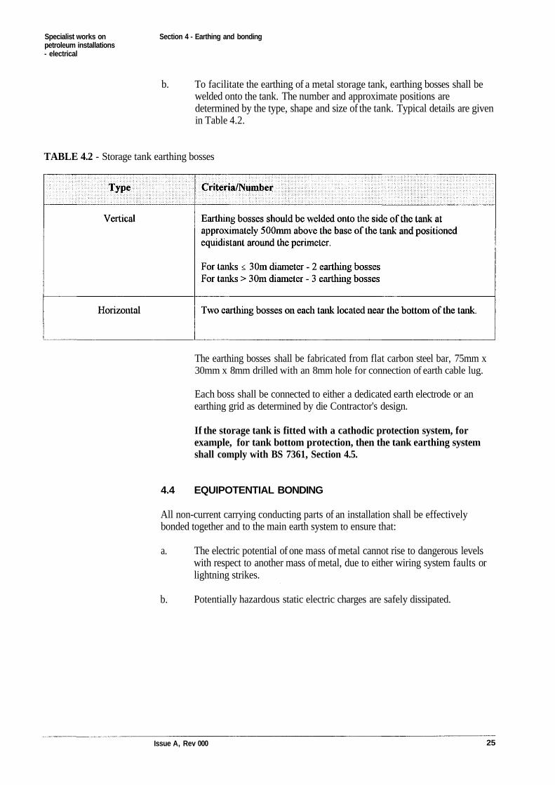
b. To facilitate the earthing of a metal storage tank, earthing bosses shall bewelded onto the tank. The number and approximate positions aredetermined by the type, shape and size of the tank. Typical details are givenin Table 4.2.
TABLE 4.2 - Storage tank earthing bosses
The earthing bosses shall be fabricated from flat carbon steel bar, 75mm x30mm x 8mm drilled with an 8mm hole for connection of earth cable lug.
Each boss shall be connected to either a dedicated earth electrode or anearthing grid as determined by die Contractor's design.
If the storage tank is fitted with a cathodic protection system, forexample, for tank bottom protection, then the tank earthing systemshall comply with BS 7361, Section 4.5.
4.4 EQUIPOTENTIAL BONDING
All non-current carrying conducting parts of an installation shall be effectivelybonded together and to the main earth system to ensure that:
The electric potential of one mass of metal cannot rise to dangerous levelswith respect to another mass of metal, due to either wiring system faults orlightning strikes.
Potentially hazardous static electric charges are safely dissipated.
Issue A, Rev 000 25
a.
b.
Specialist works on Section 4 - Earthing and bondingpetroleum installations- electrical
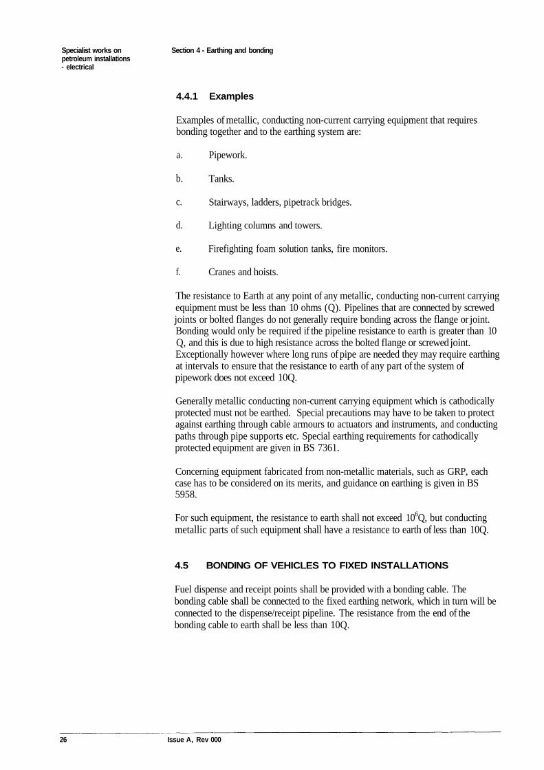
4.4.1 Examples
Examples of metallic, conducting non-current carrying equipment that requiresbonding together and to the earthing system are:
Pipework.
Tanks.
Stairways, ladders, pipetrack bridges.
Lighting columns and towers.
Firefighting foam solution tanks, fire monitors.
Cranes and hoists.
The resistance to Earth at any point of any metallic, conducting non-current carryingequipment must be less than 10 ohms (Q). Pipelines that are connected by screwedjoints or bolted flanges do not generally require bonding across the flange or joint.Bonding would only be required if the pipeline resistance to earth is greater than 10Q, and this is due to high resistance across the bolted flange or screwed joint.Exceptionally however where long runs of pipe are needed they may require earthingat intervals to ensure that the resistance to earth of any part of the system ofpipework does not exceed 10Q.
Generally metallic conducting non-current carrying equipment which is cathodicallyprotected must not be earthed. Special precautions may have to be taken to protectagainst earthing through cable armours to actuators and instruments, and conductingpaths through pipe supports etc. Special earthing requirements for cathodicallyprotected equipment are given in BS 7361.
Concerning equipment fabricated from non-metallic materials, such as GRP, eachcase has to be considered on its merits, and guidance on earthing is given in BS5958.
For such equipment, the resistance to earth shall not exceed 106Q, but conductingmetallic parts of such equipment shall have a resistance to earth of less than 10Q.
4.5 BONDING OF VEHICLES TO FIXED INSTALLATIONS
Fuel dispense and receipt points shall be provided with a bonding cable. Thebonding cable shall be connected to the fixed earthing network, which in turn will beconnected to the dispense/receipt pipeline. The resistance from the end of thebonding cable to earth shall be less than 10Q.
26 Issue A, Rev 000
a.
b.
c.
d.
e.
f.
Specialist works on Section 5 - inspection, testing of electrical equipment within hazardous areaspetroleum installations- electrical
Section 5.0
Inspection, testing and maintenance of electricalequipment within hazardous areas
5.1 GENERAL
Inspection, testing and maintenance of electrical equipment shall be undertaken inaccordance with DWS Functional Standard 07.
5.2 SAFE WORKING
All work on petroleum installations is controlled under the delegation of theOperating Authority, by the Authorised Person, AP (POL)/AP PET. Permits towork are issued by the AP (POL)/AP PET.
Electrical permits are issued by the Authorised Person (Electrical) in coordinationwith the AP (POL)/AP PET.
5.2.1 Competent personnel
Inspection, maintenance and testing in petroleum hazardous areas should only beundertaken by competent personnel who are :
Familiar with the MOD Safety Rules and Procedures for Works onPetroleum Installations, and are familiar with the MOD Safety Rules andProcedures - Electrical.
Experienced in inspection, maintenance and testing within petroleumhazardous areas.
In addition, electrical personnel should be trained and experienced in:
The principles and details of the various types of explosion protection.
Related installation practice.
The general principles of the selection of equipment for installations inhazardous areas.
Earth fault loop impedance tests, high current continuity tests and prospectiveshort circuit current tests are not to be carried out in hazardous areas. Suchtests can introduce current and/or voltages in parts of the installationthey might not be expected, due to bonding of extraneous conductive parts and
Issue A, Rev 000 27
a.
b.
c.
d.
e.
Specialist works onpetroleum installations- electrical
Section 5 - inspection, testing of electrical equipment within hazardous areas
lightning protection systems. This could result in incendive sparking in areasor parts of the installation not covered by the permit to work.
28 Issue A, Rev 000
Specialist works on Annex A - Design, contractor installation and inspectiont test certificatepetroleum installations- electrical
Annex A
Design, contractor installation and inspection\testcertificate
Electrical design certification - completed by electrical designer.Installation certification - completed by the contractor /installer.Test/commissioning certification - completed by test/commissioningengineer eg contractor/designer.Installation particulars - completed by the designer/contractor.
Issue A, Rev 000 29
Specialist works on Annex A - Design, contractor installation and inspection\test certificatepetroleum installations- electrical
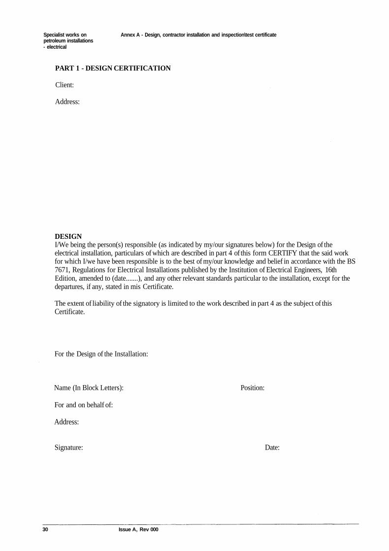
PART 1 - DESIGN CERTIFICATION
Client:
Address:
DESIGNI/We being the person(s) responsible (as indicated by my/our signatures below) for the Design of theelectrical installation, particulars of which are described in part 4 of this form CERTIFY that the said workfor which I/we have been responsible is to the best of my/our knowledge and belief in accordance with the BS7671, Regulations for Electrical Installations published by the Institution of Electrical Engineers, 16thEdition, amended to (date.......), and any other relevant standards particular to the installation, except for thedepartures, if any, stated in mis Certificate.
The extent of liability of the signatory is limited to the work described in part 4 as the subject of thisCertificate.
For the Design of the Installation:
Name (In Block Letters): Position:
For and on behalf of:
Address:
Signature: Date:
30 Issue A, Rev 000
Specialist works on Annex A - Design, contractor installation and inspection\test certificatepetroleum installations- electrical
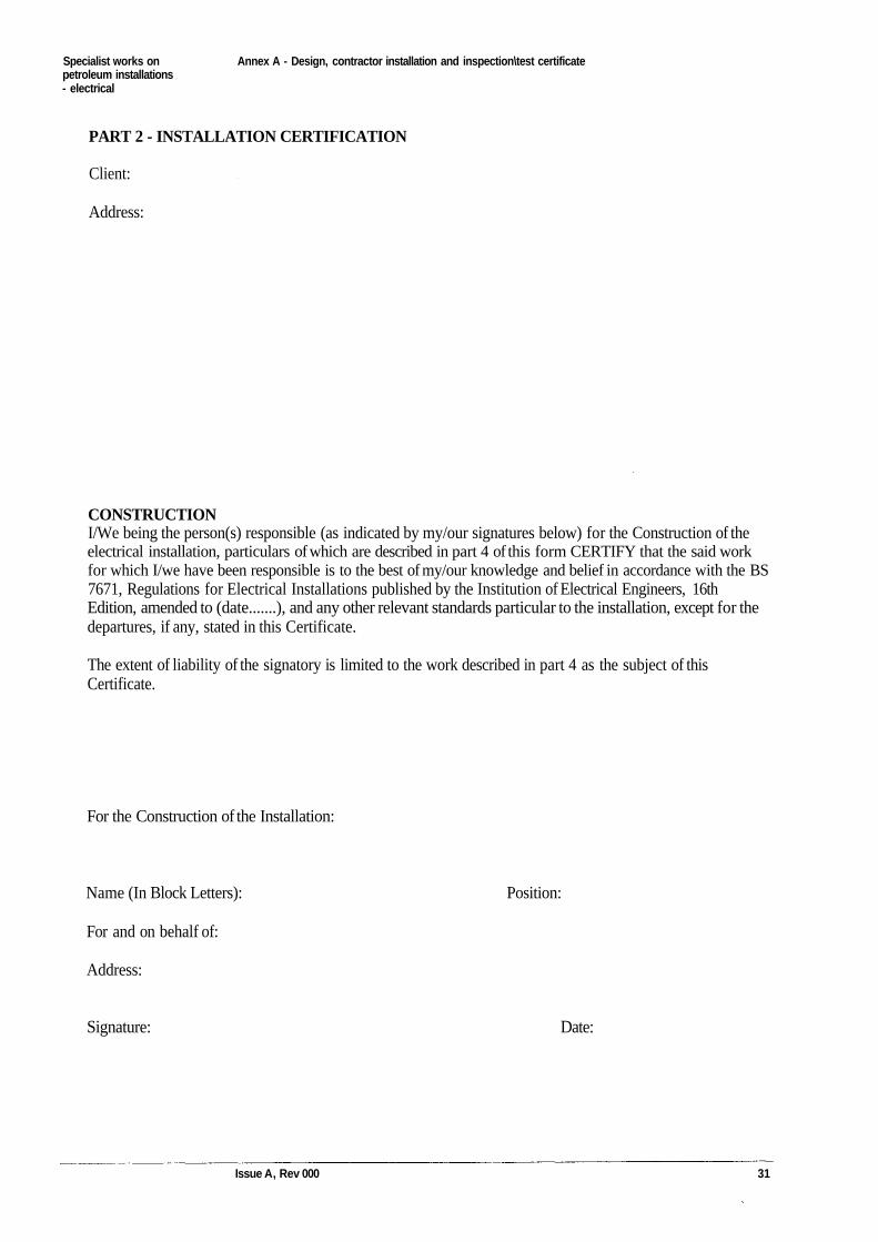
PART 2 - INSTALLATION CERTIFICATION
Client:
Address:
CONSTRUCTIONI/We being the person(s) responsible (as indicated by my/our signatures below) for the Construction of theelectrical installation, particulars of which are described in part 4 of this form CERTIFY that the said workfor which I/we have been responsible is to the best of my/our knowledge and belief in accordance with the BS7671, Regulations for Electrical Installations published by the Institution of Electrical Engineers, 16thEdition, amended to (date.......), and any other relevant standards particular to the installation, except for thedepartures, if any, stated in this Certificate.
The extent of liability of the signatory is limited to the work described in part 4 as the subject of thisCertificate.
For the Construction of the Installation:
Name (In Block Letters): Position:
For and on behalf of:
Address:
Signature: Date:
Issue A, Rev 000 31
Specialist works on Annex A - Design, contractor installation and inspection\test certificatepetroleum installations- electrical
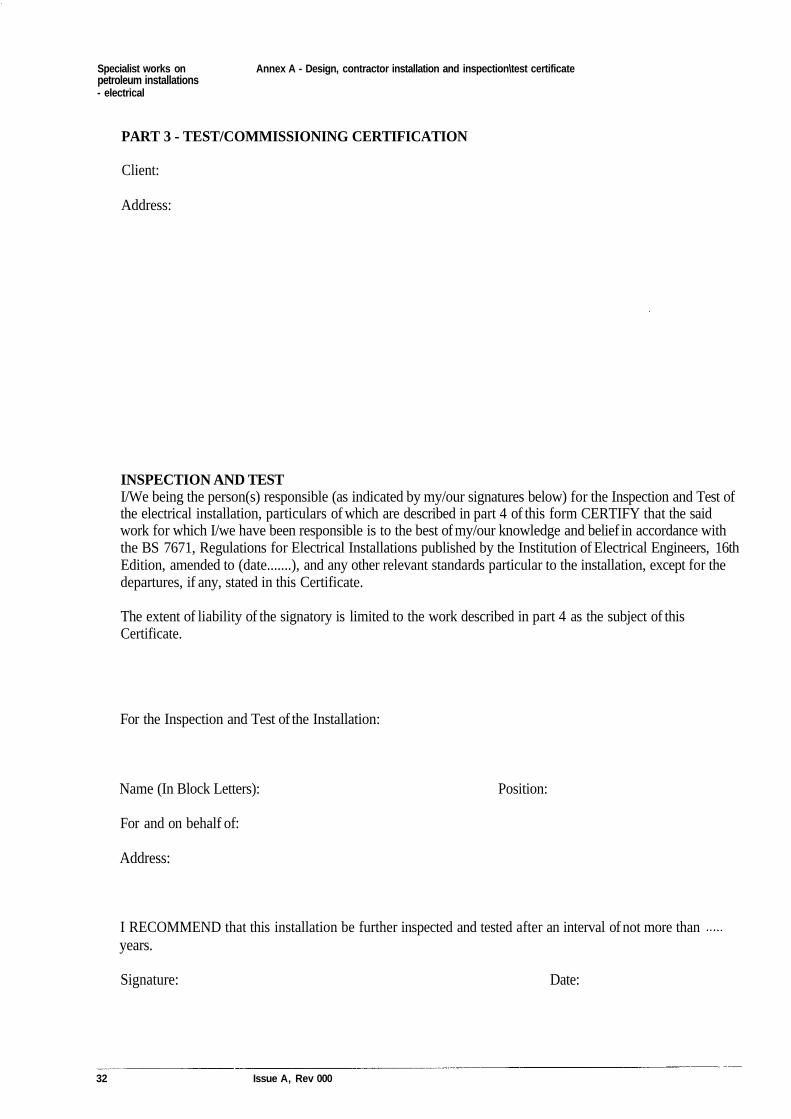
PART 3 - TEST/COMMISSIONING CERTIFICATION
Client:
Address:
INSPECTION AND TESTI/We being the person(s) responsible (as indicated by my/our signatures below) for the Inspection and Test ofthe electrical installation, particulars of which are described in part 4 of this form CERTIFY that the saidwork for which I/we have been responsible is to the best of my/our knowledge and belief in accordance withthe BS 7671, Regulations for Electrical Installations published by the Institution of Electrical Engineers, 16thEdition, amended to (date.......), and any other relevant standards particular to the installation, except for thedepartures, if any, stated in this Certificate.
The extent of liability of the signatory is limited to the work described in part 4 as the subject of thisCertificate.
For the Inspection and Test of the Installation:
Name (In Block Letters): Position:
For and on behalf of:
Address:
I RECOMMEND that this installation be further inspected and tested after an interval of not more thanyears.
Signature: Date:
32 Issue A, Rev 000
Specialist works on Annex A - Design, contractor installation and inspection\test certificatepetroleum installations- electrical
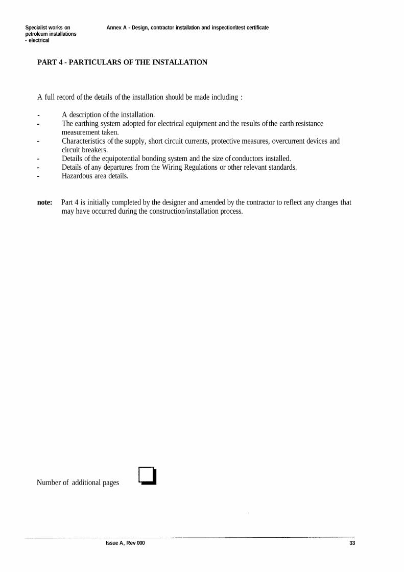
PART 4 - PARTICULARS OF THE INSTALLATION
A full record of the details of the installation should be made including :
A description of the installation.The earthing system adopted for electrical equipment and the results of the earth resistancemeasurement taken.Characteristics of the supply, short circuit currents, protective measures, overcurrent devices andcircuit breakers.Details of the equipotential bonding system and the size of conductors installed.Details of any departures from the Wiring Regulations or other relevant standards.Hazardous area details.
note: Part 4 is initially completed by the designer and amended by the contractor to reflect any changes thatmay have occurred during the construction/installation process.
Number of additional pages
Issue A, Rev 000 33
Specialist works on Annex B - Change suggestion formpetroleum installations- electrical
Annex B
Change suggestion form
34 Issue A, Rev 000
Specialist works onpetroleum installations- electrical
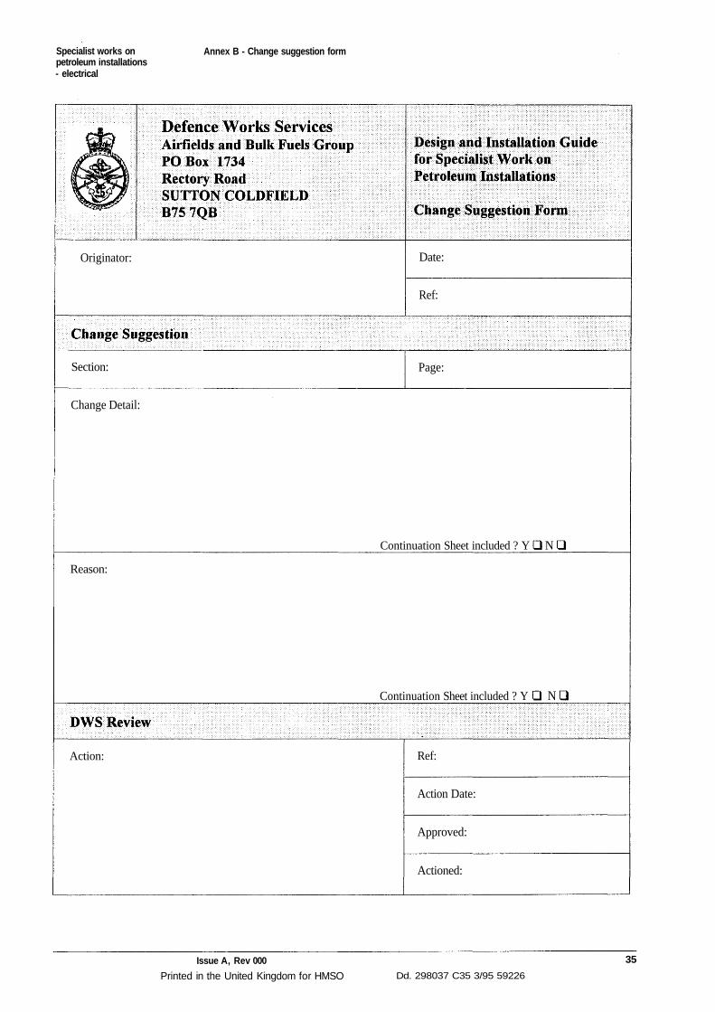
Annex B - Change suggestion form
Originator: Date:
Ref:
Section: Page:
Change Detail:
Continuation Sheet included ? Y
Reason:
Continuation Sheet included ? Y
Action: Ref:
Action Date:
Approved:
Actioned:
Issue A, Rev 000
Printed in the United Kingdom for HMSO Dd. 298037 C35 3/95 59226
35
N
N