delco ad series alternators - perfect switch, llcperfectswitch.com/downloads/delcoad.pdf · delco...
TRANSCRIPT

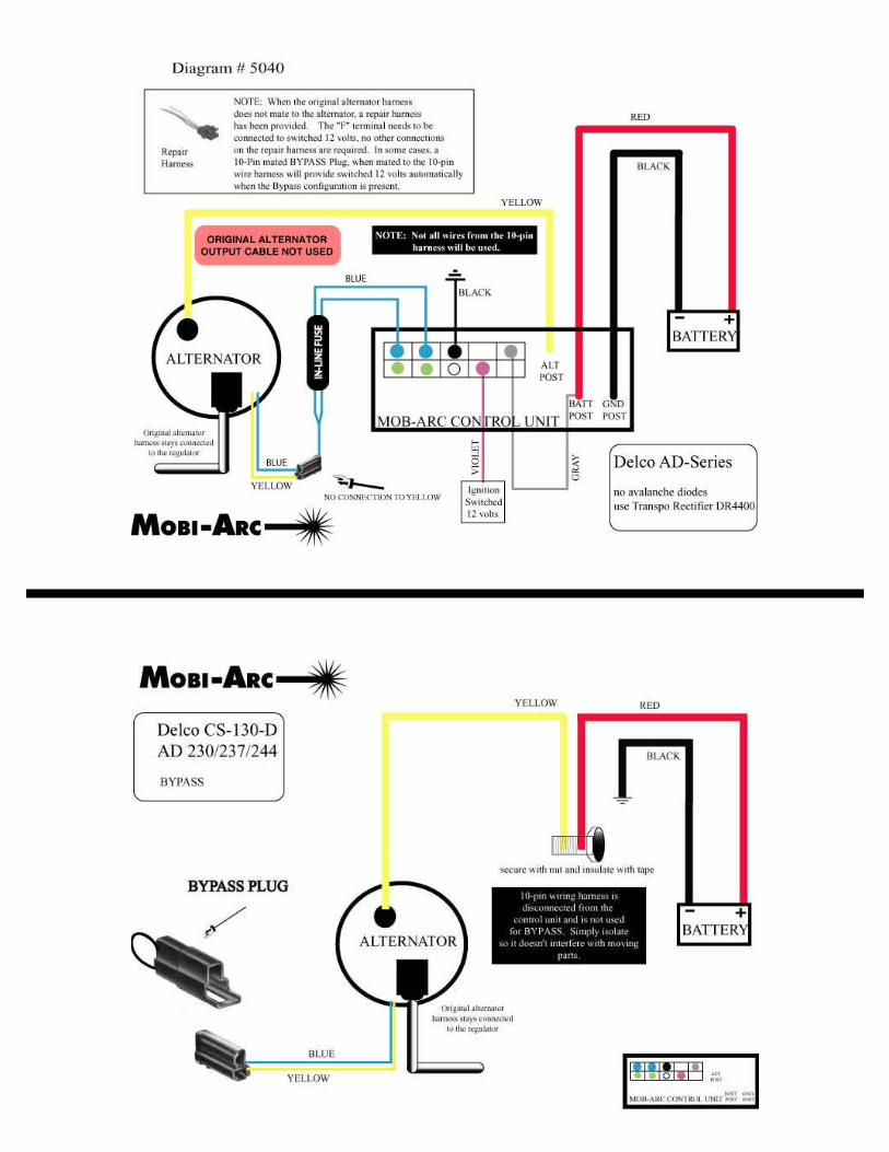
DELCO AD Series Alternators
The purpose of this modification is to allow the MOBI-ARC’s PWM regulator to control the alternator. The Delco’s regulator will be disabled while the control unit is present. By removing the 10-Pin wire harness from the back of the control unit and connecting the BYPASS plug, the Delco’s regulator is restored to its original working condition allowing standard regulation of the alternator without the control unit present. Read through these pages before undertaking modification. People not mechanically inclined may choose to have a local alternator re-builder facilitate this modification.
The AD-Series units are very good alternators; some of the best we’ve seen. Both the build quality and the components are clean and robust. In its original configuration, the AD-Series alternators use diodes within the rectifier plate known as “avalanche” diodes. Avalanche diodes are fine for charging, but they are incompatible for welding due to their limited voltage breakdown rating. In order to use the AD-Series alternators, a rectifier plate with standard diodes must be installed. We’ve manufactured bolt-in rectifier plates with standard diodes. The rectifier plates look identical, but electrically they different. Use Rectifier DR4400 Special ORGINAL AVALANCHE RECTIFIER PLATE REPLACEMENT RECTIFIER PLATE

Items required for alternator modification are as follows:
Insulator 42-1303
(2) Ring Terminal 452145, .25” stud, 16-14GA
#8 Metal Flat Washer (2)
Nylon flat washer
937825 Male (1) 937815 female (1) Bypass
925735 (2) 929875 (2)
Heavy solder iron
Blister pack thermal grease 54013LN
Remove rear plastic cover by using a small screwdriver and gently pry tabs. The arrows identify where to insert the screwdriver.

This is what the alternator looks like with the plastic rear cover removed. The component highlighted in red is the rectifier plate.
The rectifier plate is soldered to the stator wires at the three points identified by the arrows. Using a solder iron/gun, disconnect stator wires from their respective connections on the rectifier plate. Be careful not to drip solder into the alternator or let it run.
Stator connections to rectifier
After stator wires are unsoldered from the rectifier plate, unscrew the seven (7) screws identified by the arrows.
Once screws are removed, regulator and rectifier can be lifted from the alternator as demonstrated in the picture above.

Using the soldering iron, unsolder the regulator from the avalanche rectifier at the two (2) points identified by the arrows. Be careful not to pry or break tabs. They’re designed to slide apart.
The non-avalanche DR4400 Special rectifier comes with a red insulating gasket. Place gasket on rear of alternator housing as detailed in the picture to the right. A blister pack of heat transfer grease has been provided and should be smeared on the rear housing of the alternator as detailed in the picture to the right. Place non-avalanche DR 4400 Special rectifier back onto its pad on the back of the alternator.
Heat transfer grease
Insulating gasket
Place metal washers on the pads indicated by the arrows. This is critical for spacing purposes.

Insert insulator 42-1303 (identified by the green arrow) through the regulator housing and insert the screw (identified by the orange arrow). Both the insulator and the screws get loaded from the top-side of the regulator housing. From the bottom-side of the regulator, first goes the yellow wire/lug, nylon flat-washer, then blue wire/lug. Once the insulated screw is installed, again, here’s the stacking order: Yellow wire Nylon Flat-washer Blue wire
Wires oriented like picture below.
Note that regulator tabs sit on top of rectifier tabs due to the elevated spacing.
Load screws and drop regulator into place being sure that metal washers stay on pads.

After the regulator and rectifier have been secured by replacing the mounting screws, solder regulator to rectifier. The tabs sit one-on-top-of -the-other.
Crimp stator wires into their respective receptacles on the rectifier. Solder diligently.
When all components are re-installed, all screws are replaced, blue and yellow wires are oriented properly, and solder-points are sound, this is what the alternator should look like.
Route yellow and blue wires through the rear plastic cover as demonstrated to the right. Replace rear plastic cover and be sure tabs are in place. Cover should “click” into place where seated properly.