deployable arches based on regular polygon geometry
TRANSCRIPT

DEPLOYABLE ARCHES BASED ON REGULAR POLYGON GEOMETRY.
Natalia Torres. PhD Student, Polytechnic University of Catalonia. Barcelona, Spain Diana Peña. PhD. Researcher, Polytechnic University of Catalonia. Barcelona, Spain
Abstract
This paper discusses a deployable-arch-structure design that is built using articulated bars, commonly called a scissor-system, and is based on the regular polygon geometry.
The deployed-arch shape can be determined by inscribing regular polygon geometry in a circle. It is defined by the: a. number of bars required, b. position of the pivots, c. pivot-point distances, d. bar length, and e. open-geometry angle of the arches.
The goal is a deployable half dome made up of semi-arches. Traditional arch construction depends on external structures to provide stability until the keystone is set, which then allows the supports to removed. Deployable structures avoid the need for these external supports greatly simplifying the assembly process and deployment time.
Keywords: Deployable scissor structure, folding structure, portable, arches, regular polygons, dome, transformable architecture.
1
1. PRECEDENTS
1.1 GEOMETRY DEFINITIONS
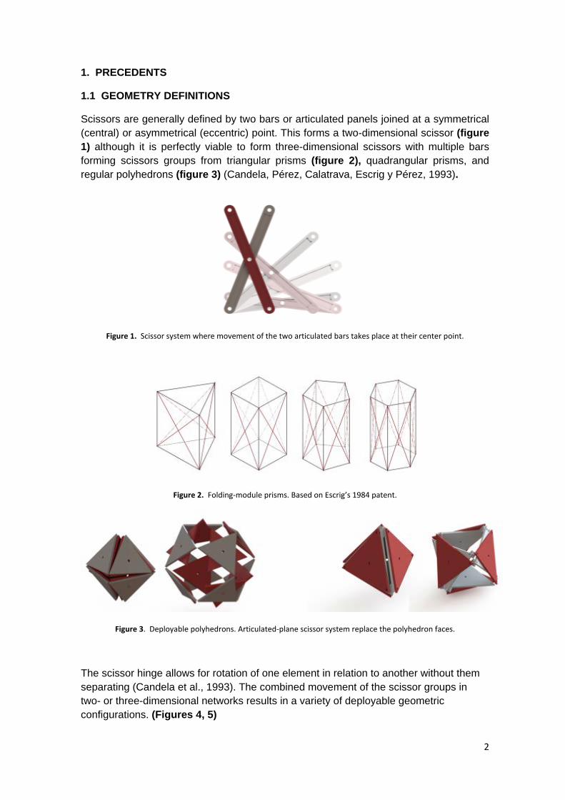
Scissors are generally defined by two bars or articulated panels joined at a symmetrical (central) or asymmetrical (eccentric) point. This forms a two-dimensional scissor (figure 1) although it is perfectly viable to form three-dimensional scissors with multiple bars forming scissors groups from triangular prisms (figure 2), quadrangular prisms, and regular polyhedrons (figure 3) (Candela, Pérez, Calatrava, Escrig y Pérez, 1993).
Figure 1. Scissor system where movement of the two articulated bars takes place at their center point.
Figure 2. Folding-module prisms. Based on Escrig’s 1984 patent.
Figure 3. Deployable polyhedrons. Articulated-plane scissor system replace the polyhedron faces.
The scissor hinge allows for rotation of one element in relation to another without them separating (Candela et al., 1993). The combined movement of the scissor groups in two- or three-dimensional networks results in a variety of deployable geometric configurations. (Figures 4, 5)
2
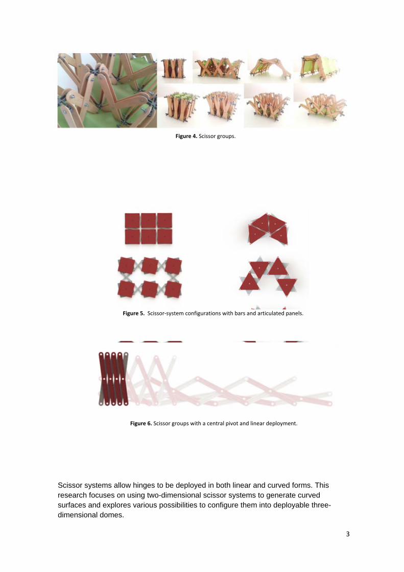
Scissor systems allow hinges to be deployed in both linear and curved forms. This research focuses on using two-dimensional scissor systems to generate curved surfaces and explores various possibilities to configure them into deployable three-dimensional domes.
Figure 4. Scissor groups.
Figure 5. Scissor-system configurations with bars and articulated panels.
Figure 6. Scissor groups with a central pivot and linear deployment.
3

Two curvature types, depending on bar geometry, are possible:
Constant Curvature
To obtain a constant curve, deployment is achieved with angled scissors along with hinges that have a pivot angle not equal to 180 degrees.
A bar group of equal angles generates rings with a concentric deployment (figure 7)
Variable Curvature
To obtain a variable curve, deployment is achieved with straight scissors and hinges placed in a straight line. The central hinge is positioned at an asymmetric distance and must comply with the following equation for a correct folding:
a + b = c + d
Figure 7. a) Angled scissors. Equilateral triangle - angle (60°). b) Straight scissors. Articulated points on a straight line. (180°).
This paper does not go in depth on angled scissors. The emphasis is on deployable scissor systems assembled formed from straight bars that result in deployable arches with variable curvatures.
The scissor groups must form symmetrical irregular quadrilaterals (deltoids) and able to be folded. From this, a deployment with variable curvature is obtained. There is also the possibility to form symmetrical diamonds, which results in a linear deployment. (Figure 8)
4

Figure 8. a) Regular quadrilaterals = linear deployment. b) Deltoid = variable curvature deployment. c) Irregular quadrilaterals = can not be folded.
The following section covers the most common geometric methods used by leading deployable-structure designers to generate curved surfaces.
1.2 PEREZ PIÑERO METHOD
Emilio Perez Piñero is recognized as a pioneer in the design and application of deployable structures in architecture. Building on Piñero’s work, Lina Puertas del Rio created typologies to form spherical surfaces from deployable structures (Puertas, 1989) (Figure 9) including those listed below.
- Square grids:
Formed by projecting a grid of squares onto two concentric spherical surfaces with lines starting in one central point and intersecting the vertices of the two parallel planes traced on the surfaces.
- Triangular and rectangular grids:
Formed by projecting a square grid onto two concentric spherical surfaces but with the addition of diagonal lines. In this case, the system consists of more and different length bars.
- Equilateral-triangle grids:
Formed by tracing equilateral triangles vertices onto spherical surfaces generating the base unit with three scissors, thus achieving greater uniformity between bars. Another
5
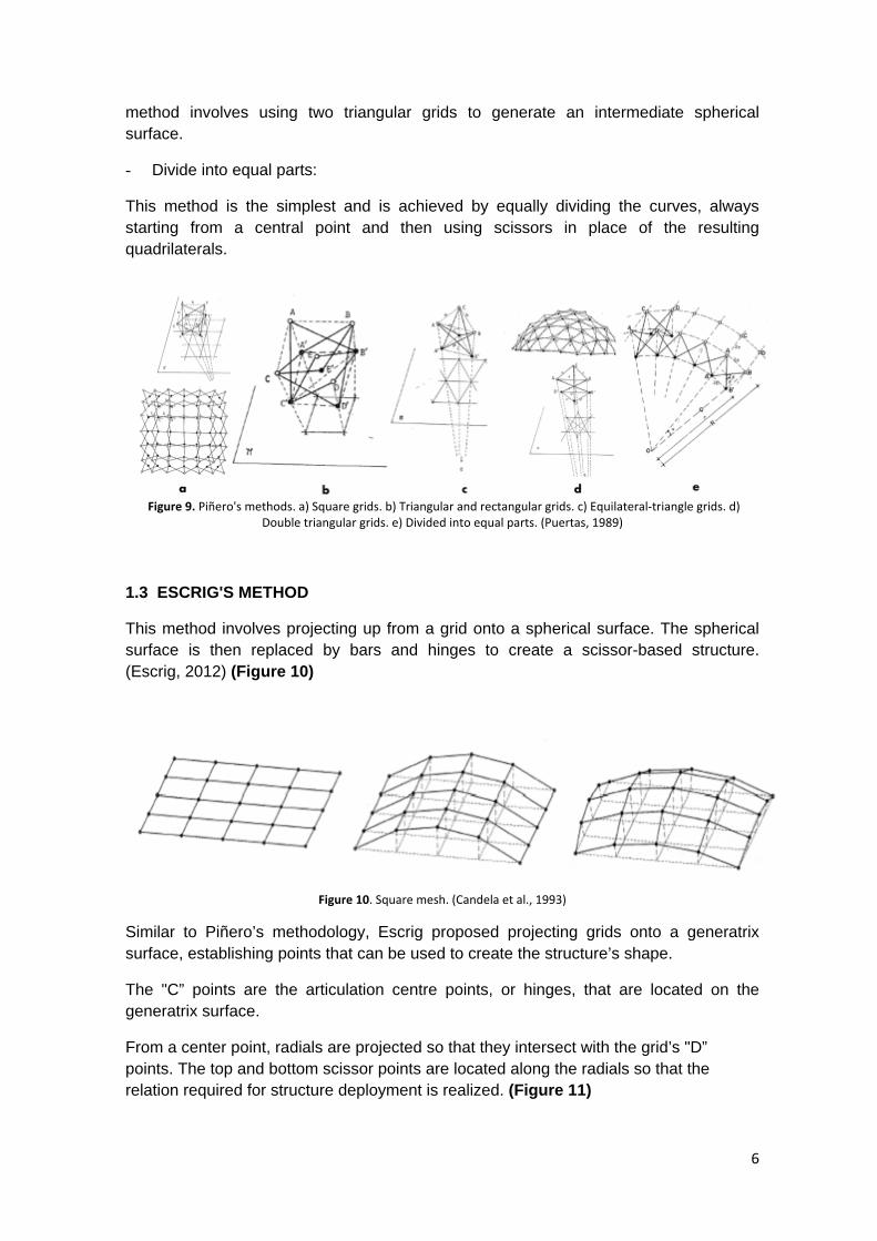
method involves using two triangular grids to generate an intermediate spherical surface.
- Divide into equal parts:
This method is the simplest and is achieved by equally dividing the curves, always starting from a central point and then using scissors in place of the resulting quadrilaterals.
Figure 9. Piñero's methods. a) Square grids. b) Triangular and rectangular grids. c) Equilateral-triangle grids. d) Double triangular grids. e) Divided into equal parts. (Puertas, 1989)
1.3 ESCRIG'S METHOD
This method involves projecting up from a grid onto a spherical surface. The spherical surface is then replaced by bars and hinges to create a scissor-based structure. (Escrig, 2012) (Figure 10)
Figure 10. Square mesh. (Candela et al., 1993)
Similar to Piñero’s methodology, Escrig proposed projecting grids onto a generatrix surface, establishing points that can be used to create the structure’s shape.
The "C” points are the articulation centre points, or hinges, that are located on the generatrix surface.
From a center point, radials are projected so that they intersect with the grid’s "D” points. The top and bottom scissor points are located along the radials so that the relation required for structure deployment is realized. (Figure 11)
6

Figure 11. The articulated points are projected radially. (Candela et al., 1993)
Another method involves projecting points onto a sphere from an arbitrary focus, which allows for the visualization of the unfolded geometry to be used for dome design. (Figure 12)
Figure 12. Projecting points onto a sphere - different possibilities. (Escrig, 2012)
Another method is based on regular polyhedron geometry (Escrig, 2012). This example could be used for a portable-pavilion design based on a rhombicuboctahedron and is adaptable as a pavilion or kiosk. The geometry allows for edges to be replaced by scissors, which results in a perfectly folding kit. (Figure 13)
Figure 13. Portable exhibition pavilion. (Escrig, 2012)
A final approach relevant to this research is Escrig’s sphere division in parallels and meridians. The images show the angular relation required to guarantee that the scissor units are deployable. (Figure 14)
7

Figure 14. Sphere division in parallels and meridians. (Escrig, 2012)
1.4 GANTES METHOD
The Gantes method involves projecting an ellipse that will form the arch axis. By projecting two equidistant ellipses from the first ellipse axis, it is possible to obtain a top surface that can be divided into equal sections (Gantes, 2004).
The base lines originate from the center of the ellipse and intersect with the origin points of the equidistant ellipses. The adjacent segments become the scissor nodes. The scissor angle when fully open determines the width of the arch.
This study proposes equations and a equation-validation method to test the possibility of a deployable arch with both variable-length bars and a variable-surface curvature. These features result in a repeating modular unit that facilitates the assembly process. (Figures 15)
Figure 15. Geometric design of complex-curved surface (Gantes, 2004)
1.5 BABAEI'S RESEARCH
Babaei’s work shows various deployable-arch geometries that are generated using algebraic equations (Babaei, 2009). The illustrated arch typologies result from changing the geometric relation of each successive scissor’s inside angle. (Figures 16)
8
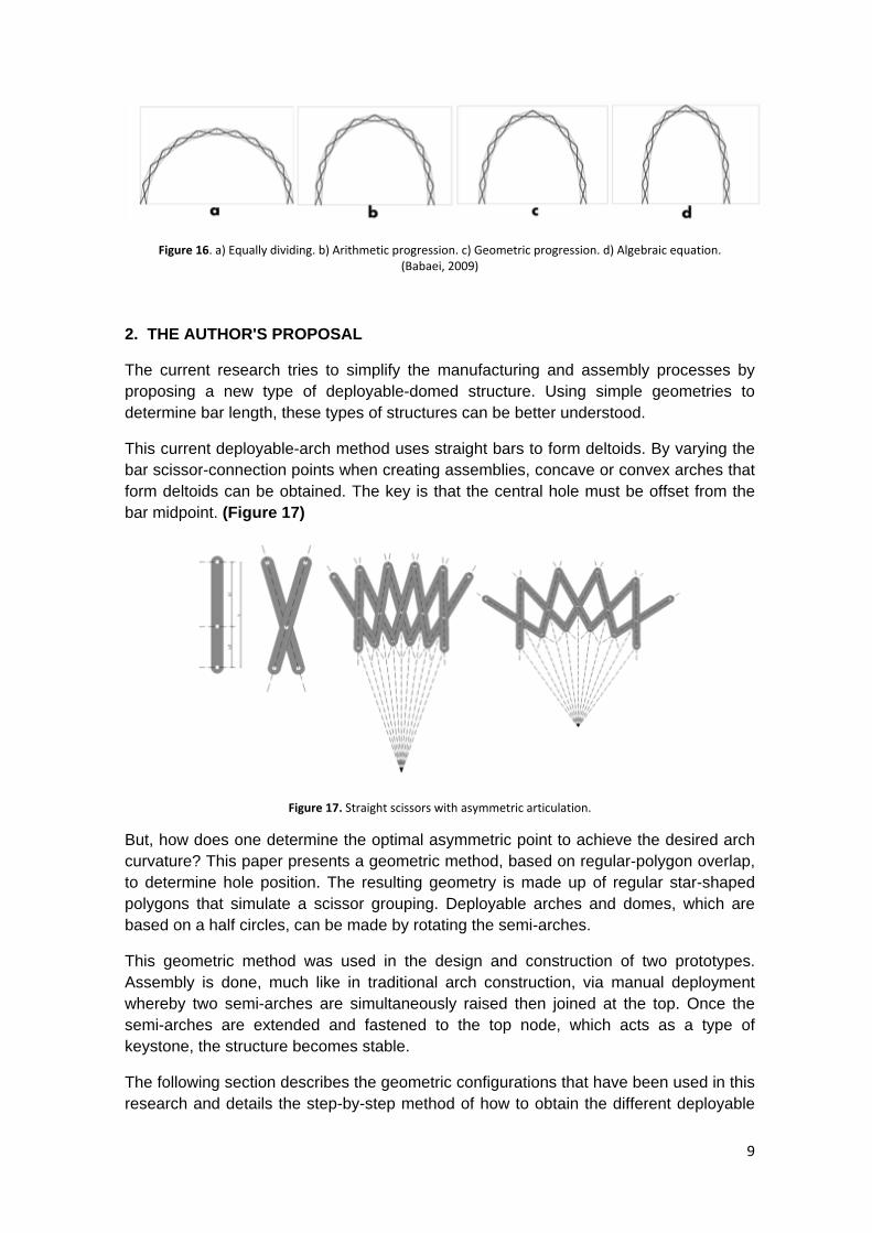
Figure 16. a) Equally dividing. b) Arithmetic progression. c) Geometric progression. d) Algebraic equation. (Babaei, 2009)
2. THE AUTHOR'S PROPOSAL
The current research tries to simplify the manufacturing and assembly processes by proposing a new type of deployable-domed structure. Using simple geometries to determine bar length, these types of structures can be better understood.
This current deployable-arch method uses straight bars to form deltoids. By varying the bar scissor-connection points when creating assemblies, concave or convex arches that form deltoids can be obtained. The key is that the central hole must be offset from the bar midpoint. (Figure 17)
Figure 17. Straight scissors with asymmetric articulation.
But, how does one determine the optimal asymmetric point to achieve the desired arch curvature? This paper presents a geometric method, based on regular-polygon overlap, to determine hole position. The resulting geometry is made up of regular star-shaped polygons that simulate a scissor grouping. Deployable arches and domes, which are based on a half circles, can be made by rotating the semi-arches.
This geometric method was used in the design and construction of two prototypes. Assembly is done, much like in traditional arch construction, via manual deployment whereby two semi-arches are simultaneously raised then joined at the top. Once the semi-arches are extended and fastened to the top node, which acts as a type of keystone, the structure becomes stable.
The following section describes the geometric configurations that have been used in this research and details the step-by-step method of how to obtain the different deployable
9

arch geometries. Software analysis and the construction of scale models is used to validate the model.
2.1 GEOMETRY DEFINITION
The method used to define the deployable-arch geometry is based on geometric patterns. Taking the circle as the geometric regular-polygon base; similar to the technique used in traditional Islamic mosaics applied to decorative elements in walls, ceilings, and doors where their designs are based on geometric patterns.
This technique allows segments based on scissor groups inscribed inside a circle to be visualized and, in this specific case, arches formed by articulated bars to be designed. By setting the diameter, bar length, and hole position, the desired curvature can be obtained.
Some basic values for the different arch configurations are set:
• Six-meter-diameter circles serve as the polygon geometric base. • Dome height is three meters, which equals the radius of the base.
Steps
The geometry begins with a circle divided into four or more sections. From there, lines are drawn that join the vertices with every other vertex to form two polygons. An example of the step-by-step construction of a polygon, in this case a hexagon:
1. Draw a circle and divide it into the number of desired polygon sides multiplied by two. For our example, a hexagon has six sides: N = 6.
The circle is then divided into 2*N (12) sections. (Figure 18)
2. Connect every second vertex to create the first hexagon. (Figure 19)
3. Connect the remaining vertices to construct the second hexagon. The result is a polygon star formed by two overlapping and rotated hexagons. (Figure 20)
4. Take half the circumference and mark the intersecting points between the sides of the polygons and the radial angles. These points mark the estimated bar length and hole positions.
10
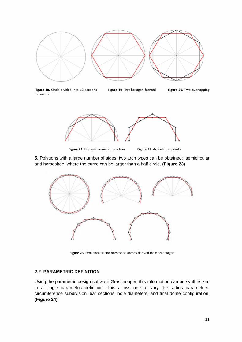
Figure 18. Circle divided into 12 sections Figure 19 First hexagon formed Figure 20. Two overlapping hexagons
Figure 21. Deployable-arch projection Figure 22. Articulation points
5. Polygons with a large number of sides, two arch types can be obtained: semicircular and horseshoe, where the curve can be larger than a half circle. (Figure 23)
Figure 23. Semicircular and horseshoe arches derived from an octagon
2.2 PARAMETRIC DEFINITION
Using the parametric-design software Grasshopper, this information can be synthesized in a single parametric definition. This allows one to vary the radius parameters, circumference subdivision, bar sections, hole diameters, and final dome configuration. (Figure 24)
11

Describing the dome parametrically allows both design and, ultimately, the structure’s manufacturing process to be optimized.
Figure 24. Deployable-arch parametric definition.
3. POLYGONAL DOME SUMMARY
The objective is to build a structure that is deployed simultaneously in both plan and elevation. It is proposed that the semi-arches rotate around the z axis with a rotation angle corresponding to the desired polygon shape. From this, scissor groups can be projected in horizontal plane, which directly relates to the vertically deployed arches. (Figure 25)
To allow the study of other geometric possibilities of regular polygons, the following method-summary table is provided. It distinguishes the following four key elements: polygon type, scissor group, bar length, positioning holes and axonometric domes with their height and possible outcomes. (Table 1, table 2)
Figure 25. Axonometric dome.
12

Table 1. Bar length and positioning holes
Table 2. Polygonal dome summary
13

Figure 26. Deployable polygons with straight scissors.
Figure 27. Deployable domes.
14

4. PROTOTYPE CONSTRUCTION
To bring the deployable arch implementation to life, a deployable (performance) stage and a deployable kiosk were designed for temporary-event use at the School of Architecture, Art and Design, at the Monterrey Institute of Technology and Higher Education in Mexico.
4.1 PROTOTYPE I. DEPLOYABLE STAGE
Design
The prototype is a half dome with a regular heptagon geometric base the diameter of which was adjusted to the maximum height possible in the room where the stage was installed.
The arches were three meters high and horseshoe shaped. The plan has a circumference with a six-meter diameter, which includes the arch bases.
The prototype has five deployable arches, a folding-platform floor structure, and elastic-fabric covers between the arches (Torres, 2013).
Figure 28. Deployable stage made from cardboard tubing.
Materials Bars: cardboard tubes. Diameter: 5 cm. Thickness: 5 mm Separators: bamboo. Diameter: 2 cm Foldable platform: American pine beams and laminated-chipboard panels (recycled from old architectural drawing tables) Cover: Lycra. Top node: composite-aluminum sheet Connecting hinges and screws: steel
15

Construction The deployable arch is made from sixteen 1,36 meter-long cardboard tubes. For increased stability, a double layer of each arch was built. Varying-length bamboo spacers were placed between the double arches, which made the base of each arch wider at the bottom and narrower at the top.
Figure 29. Arch assembly.
For the each arch base, two boxes with laminated-chipboard panels were designed to articulate the arches and receive the beam that support the floor panels. The box length is such that it limits arch deployment and the interior is sized to provide space for counterweights while the stage is in use.
Figure 30. Base manufactured using a 3D printer. Scale model: arch base.
16
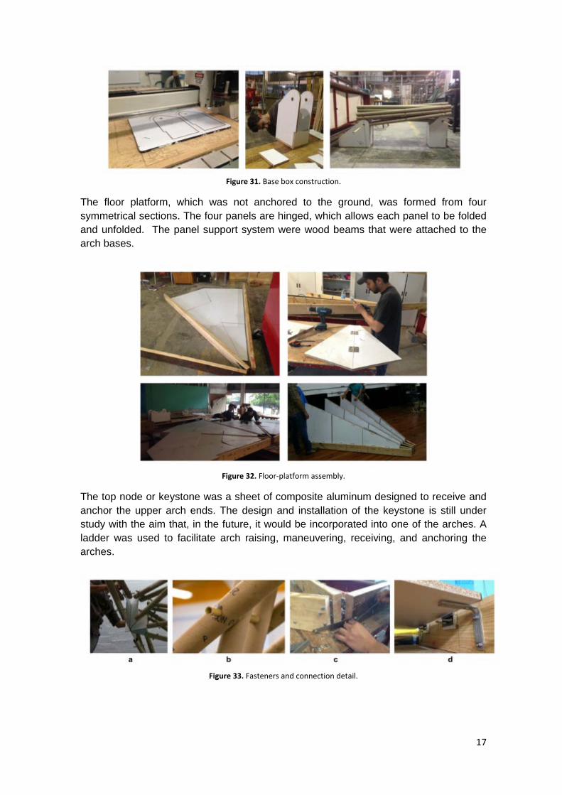
Figure 31. Base box construction.
The floor platform, which was not anchored to the ground, was formed from four symmetrical sections. The four panels are hinged, which allows each panel to be folded and unfolded. The panel support system were wood beams that were attached to the arch bases.
Figure 32. Floor-platform assembly.
The top node or keystone was a sheet of composite aluminum designed to receive and anchor the upper arch ends. The design and installation of the keystone is still under study with the aim that, in the future, it would be incorporated into one of the arches. A ladder was used to facilitate arch raising, maneuvering, receiving, and anchoring the arches.
Figure 33. Fasteners and connection detail.
17
Assembly The stage was made from of six components:
1. Beams. 2. Panels. 3. Base. 4. Arches. 5. Top node (keystone). 6. Membrane.
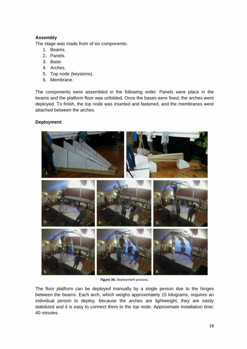
The components were assembled in the following order: Panels were place in the beams and the platform floor was unfolded. Once the bases were fixed, the arches were deployed. To finish, the top node was inserted and fastened, and the membranes were attached between the arches. Deployment
Figure 34. Deployment process.
The floor platform can be deployed manually by a single person due to the hinges between the beams. Each arch, which weighs approximately 15 kilograms, requires an individual person to deploy. Because the arches are lightweight, they are easily stabilized and it is easy to connect them to the top node. Approximate installation time: 40 minutes
18
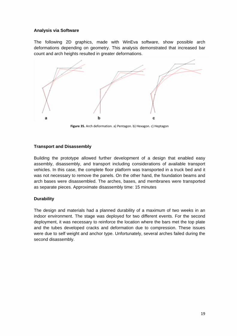
Analysis via Software The following 2D graphics, made with WinEva software, show possible arch deformations depending on geometry. This analysis demonstrated that increased bar count and arch heights resulted in greater deformations.
Figure 35. Arch deformation. a) Pentagon. b) Hexagon. c) Heptagon
Transport and Disassembly Building the prototype allowed further development of a design that enabled easy assembly, disassembly, and transport including considerations of available transport vehicles. In this case, the complete floor platform was transported in a truck bed and it was not necessary to remove the panels. On the other hand, the foundation beams and arch bases were disassembled. The arches, bases, and membranes were transported as separate pieces. Approximate disassembly time: 15 minutes Durability The design and materials had a planned durability of a maximum of two weeks in an indoor environment. The stage was deployed for two different events. For the second deployment, it was necessary to reinforce the location where the bars met the top plate and the tubes developed cracks and deformation due to compression. These issues were due to self weight and anchor type. Unfortunately, several arches failed during the second disassembly.
19

4.2 PROTOTYPE II. DEPLOYABLE KIOSK
Figure 36. Front view - Deployable kiosk.
Design The prototype was designed as a half-dome deployable kiosk. The structure was 3.00 meters in diameter and 2.45 meters high. The main design goal was the ability to simultaneously extend both the arch (vertical) and floor (horizontal) scissors. The arches are designed to stop just short of vertical so that they can be fixed to the top plate but not so far as to cause the structure to roll over during deployment. This proposal did not include a platform, which made the structure lighter. The stage includes nine deployable arches, a base structure also formed by scissors, and elastic fabric between the arches.
Figure 37. Deployable Stand.
20

Materials Arch bars: Rectangular aluminum bar = 1.00” x 0.50” Separators: Aluminum tubing = 0.325” x 0.05” Fabric cover: White Lycra Keystone: Aluminum-composite sheet Connectors: Steel Construction Arches: Each deployable arch was formed by 19 aluminum rectangular bars that were 0.72 meters in length. As in the first prototype, greater stability was obtained by using a double layer of deployable arches. The base structure was an arch defined by a scissor group, the base of which was a heptagon. This design optimized the opening (door) size with the maximum possible floor space.
Figure 38. Assembly process.
The top node or keystone had a new plastic design, which received the upper arch ends and was fastened with screws. In this case, the design progressed by using digital printing, but, it should be noted the first attempt did not fit and needed to be redesigned. (Fig 39) To assist in attaching the top node to the arches, a ladder was used.
Figure 39. Connections and details.
21

Assembly The kiosk was made up of five parts:
1. Nine vertical deployable arches. 2. Connection nodes. 3. Top centre piece (keystone). 4. Horizontal deployable arch. 5. Fabric membrane.
The nodes allow the horizontal arch to be connected to the nine vertical arches. Once the structure is deployed, the top centre piece is inserted and connected to the arches then the membranes are fixed between arches. Deployment The slenderness and quantity of vertical arches complicated the deployment and required a minimum of five people to stabilize the structure. Once the top center node was inserted and connected, the structure became stable and fairly rigid. Similar to traditional arch construction where stability occurs once the keystone is set, the structure became stable when the center node was connected. The structure was raised into place by four people while a fifth fastened the center node and arches. Approximate weight: 40 Kg. Approximate assembly time: 20 minutes
Figure 40. Deployment process.
22

Transport and Disassembly
The structure was separated into two parts, which allowed it to fit into the trunk of a small car. Compared to assembly, disassembly was much quicker. Once the top node was disconnected, the structure was easily collapsed.
Approximate disassembly time: 10 minutes
Durability
The deployable kiosk was designed to last five years. As of this writing, the structure has been successfully used for three different events for a minimum of five days per event and remains in excellent condition. Current investigation focuses on improved deployment and covering and the optimal top-node design.
5. CONCLUSIONS
After the geometric analysis and the construction of the prototypes, the following can be concluded:
- The proposed method allows for the design of arches and an assembly system, which is based on traditional arch construction. This is done through the use of two principal concepts: (1) regular polygon geometry and (2) deployable structures with articulated bars that are also called scissor systems. Using this methodology, it is possible to optimize the design and assembly of deployable domes.
- The regular polygon geometry determines the: Arch curvature. Bar quantity and length. Bar mounting-hole location (hinge point). Arch opening limit to achieve the proposed curvature. Arch final deployable state.
- Arches based on polygon geometries. The network of lines that is generated serve
as a guide to join scissor groups with eccentric articulations, which allows different types of geometries to be visualized. (Semicircular or horseshoe arches)
- The deployable-structure scissor-hinge system allows the arch to be assembled by
means of two parts joining together at the peak (matching traditional arch construction). This proposal, as a deployment structure, avoids the need for any external structure or supports during assembly thus simplifying and speeding up the process.
- The proposed scissor system is easy to manufacture, assemble, and install as the modular elements optimize construction.
23

- The geometry form-finding process utilized in this research allowed for the development of a parametric definition, which established the fundamental geometry basics. It was able to be used to define parameter variables such as: The circumference diameter and the number of segments it can be divided into; bar length, thickness, and geometry; and the hole diameter for the connections between bars. This allows for dome geometries to be calculated and adjusted very quickly, which enables design flexibility.
- Each of the parametric designs has generated valuable solutions to the geometric concept, which results in more efficient design, manufacturing, and assembly. In addition, a new way to design deployable structures through variable geometric parameters was developed, allowing several domes for different architectural requirements to be designed.
- Building and assembling the prototypes allowed the deployment process, the impact of bar material on performance and durability, and transport and assembly challenges to all be observed.
- Future research will investigate the maximum opening point of the arches, taking into account the top node weight and structure deformation, to obtain the exact geometry.
The methodology presented here is a geometric process that has been tested with prototypes, structural studies, and load analysis. This research is still in process, with the aim to optimize the deployment time and resolve the top node geometry.
Figure 41. Structural testing.
24

REFERENCES
Babaei, M. & Sanaeia , E. (2009). Geometric and Structural Design – Foldable Structures. International Association for Shell and Spatial Structures Proceedings (IASS) Symposium.
Candela, F., Pérez, E., Calatrava, S., Escrig, F & Pérez, J. (1993). Arquitectura Transformable. Textos de arquitectura. Escuela Técnica Superior de Arquitectura, Sevilla, España.
Torres, N. (2013). Desarrollo de un escenario desplegable basado en la aplicación de estructuras tipo tijera, sistema de plegadura y membranas. New proposal for transformable architecture, engineering and design. In honor of Emilio Pérez Piñero. First Conference Transformable Proceedings, 125-130.
Escrig, F. (2012). Modular, ligero y transformable. Un paseo por la arquitectura ligera móvil. Universidad de Sevilla, España
Gantes, C & Konitopoulou, E. (2004). Geometric design of arbitrarily curved bi-stable deployable arches with discrete joint size. International Journal of Solids and Structures. Vol. 4.
Puertas, L. (1989). Estructuras espaciales desmontables y desplegables. Estudio de la Obras del arquitecto Emilio Pérez Piñero. Tesis doctoral. Escuela Técnica Superior de Arquitectura de Madrid, España.
25