design & constr. complexities of yerba buena island
TRANSCRIPT

Design & Constr. Complexities of Yerba Buena Island Transition
Structures for SFOBB - East Spans
Authored by: Robert Dameron; Gernot Komar; Al Ely; Tony Sánchez; Jal Birdy; Brian Maroney
Presented by: Robert Dameron
Western Bridge Engineers Seminar Sept. 10, 2015
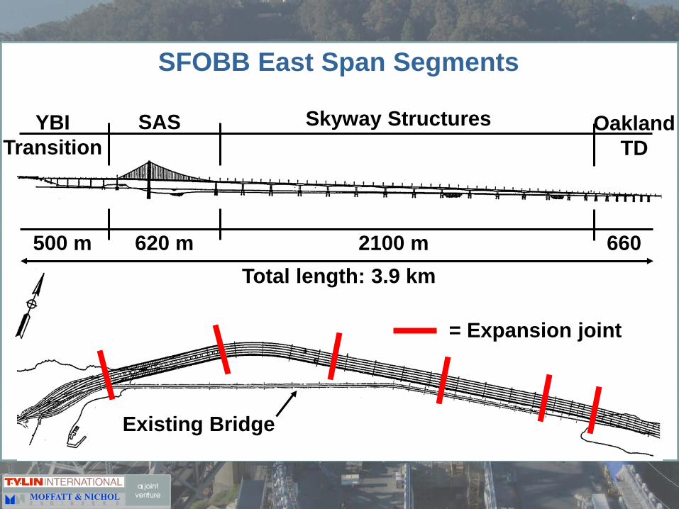
SFOBB East Span Segments
YBITransition
SAS Skyway Structures OaklandTD
Total length: 3.9 km2100 m620 m500 m 660
Existing Bridge
= Expansion joint

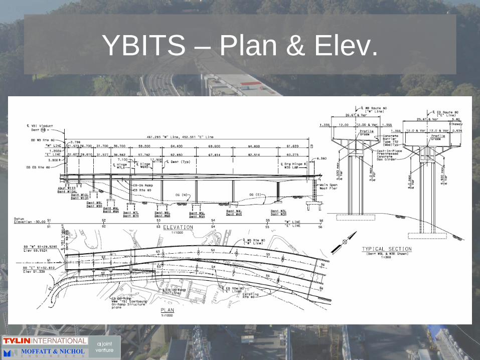
Yerba Buena Island Transition Structure: Geometry Challenges
• Deck Heights: 3m to 51m• Westbound Transition
– 460 meters; 2 Frames– Frame 1:
• Conventional Reinforced Concrete
• Spans are 21.6m to 36.7m– Frame 2:
• Post-tensioned Concrete• Spans are 59.2m to 84.8m
• EB and WB transition from Parallel to Double-Deck Structures
• Outrigger Bents
YBITS – Plan & Elev.

Seismic Design Criteria and Expected Performance
Two Levels of Ground Motions
1. Functional Evaluation Earthquake (FEE):
• 92 yr return period or • 80% probability of
exceedance in 150-year design life
2. Safety Evaluation Earthquake (SEE):
• 1500 yr return period or
• 10% probability of exceedance in 150-year design life
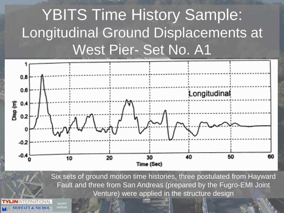
YBITS Time History Sample:Longitudinal Ground Displacements at
West Pier- Set No. A1
Six sets of ground motion time histories, three postulated from Hayward Fault and three from San Andreas (prepared by the Fugro-EMI Joint
Venture) were applied in the structure design
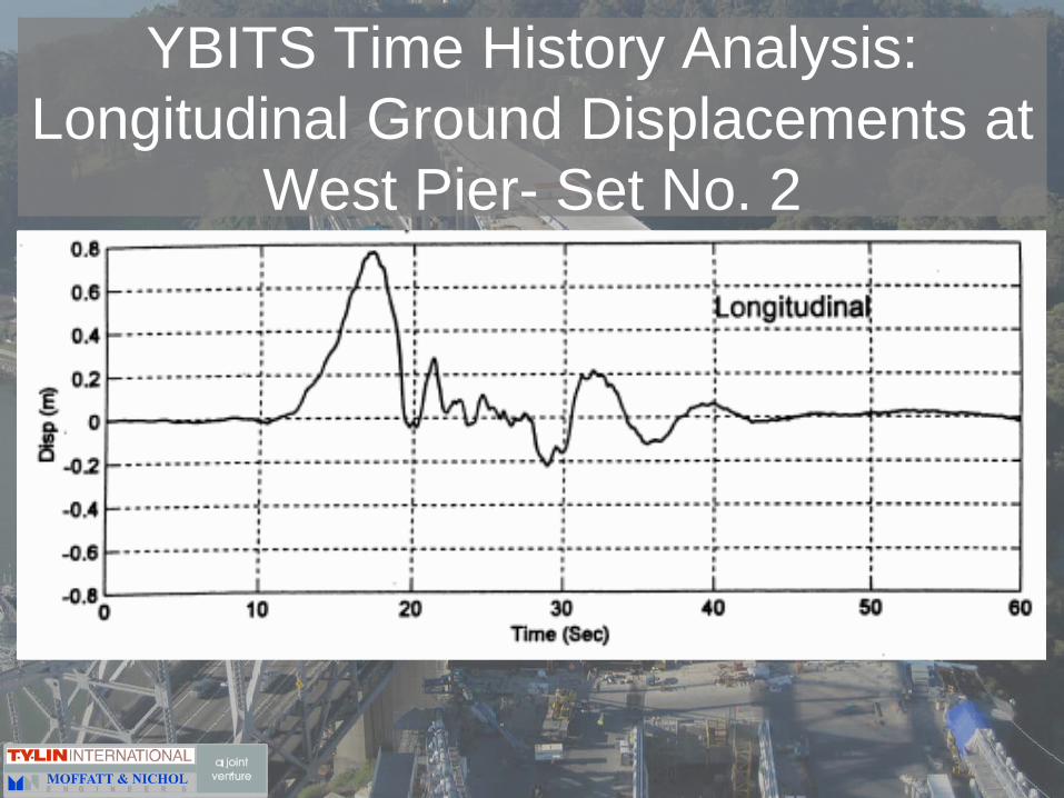
YBITS Time History Analysis:Longitudinal Ground Displacements at
West Pier- Set No. 2
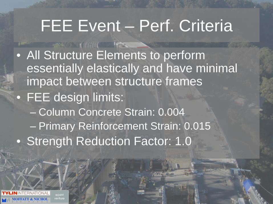
FEE Event – Perf. Criteria
• All Structure Elements to perform essentially elastically and have minimal impact between structure frames
• FEE design limits:– Column Concrete Strain: 0.004– Primary Reinforcement Strain: 0.015
• Strength Reduction Factor: 1.0

SEE Event – Perf. Criteria• All Structure Elements except Columns remain
essentially elastic; impact between frames is expected but unseating of hinges and abutments not allowed
• Columns– Ultimate Strain in Columns Primary Reinforcement
• 0.12 (confinement bars #13 - #25)• 0.09 (main bars #29 - #57)
– Relative Displacement Demands: 80% of calculated capacity– Column Shear Capacity: SDC - 1999
• Superstructure, Bent Caps & Column Footings– Maximum Moment induced by columns
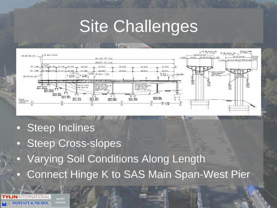
Site Challenges
• Steep Inclines• Steep Cross-slopes• Varying Soil Conditions Along Length • Connect Hinge K to SAS Main Span-West Pier

YBITS – Westbound Frame 2Ductile System with Plastic Hinging

Analysis and Design Overview: Substructure
• Pushover Analyses: Column Transverse & Longit. Displacement Capacities• NASTRAN: Longitudinal behavior of the frame
FEE Demand (10.1”)
SEE Demand (26.9”)

Response Spectrum Analysis• mass distribution well discretized to nodes• Releases between adjoining frames at hinges• Linear Fdn. Springs to represent fdn. flexibility• Both “tension” and “compression” models analyzed• 1st Period WB: 3.32 sec (long); 3.01 sec (transv.)• Peak Displacement WB: 26 in (long); 28 in (trans)

YBITS – WestboundResponse Spectrum Analysis

YBITS – Connected Westbound Structure Response Spectrum Analysis
Mode Shapes
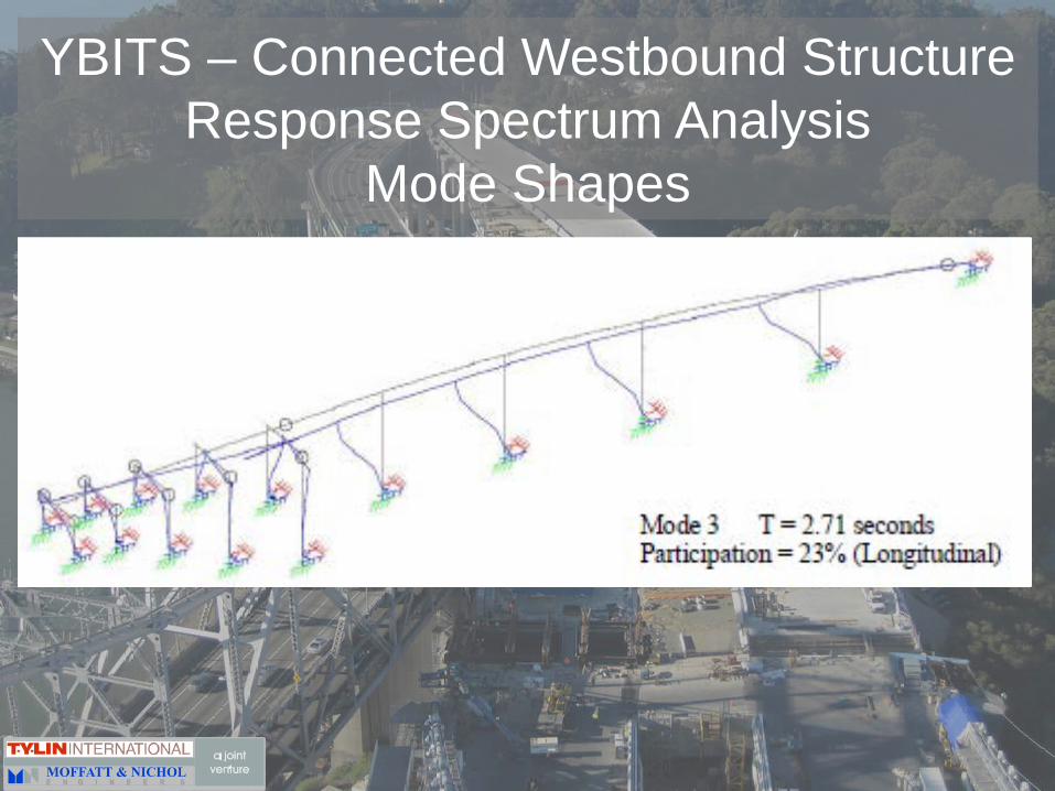
YBITS – Connected Westbound Structure Response Spectrum Analysis
Mode Shapes

• NASTRAN Model used for Elastic and Inelastic Time History Analysis
• Average Peak Demands to Capacity Displacement Ductility Ratios of 1.8– Tall Piers ~1– Short Piers Max 4.2 (Transv. Direction) WB and 5.4 EB

• Modular Expansion Joints:– FEE Event: Fully Functional– SEE Event: Beyond normal operating range resulting
in tearing or parting of flexible seals – Used Between Frames 1 & 2 and ramps
• State Developed Joints w/ Steel Bridging Plates:– SEE Event
• Bridging Plates Maintain Bearing• Seat Width allows full movement• Restrainer cables engage with full SEE gap
– Used at East and West Ends of YBITS (Abut 10 & 11 and Hinge K)
Analysis and Design Overview:Superstructure and Hinges

Construction
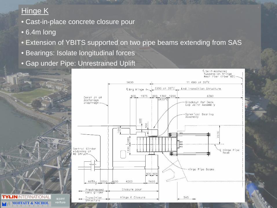
Hinge K• Cast-in-place concrete closure pour• 6.4m long• Extension of YBITS supported on two pipe beams extending from SAS• Bearings: Isolate longitudinal forces• Gap under Pipe: Unrestrained Uplift
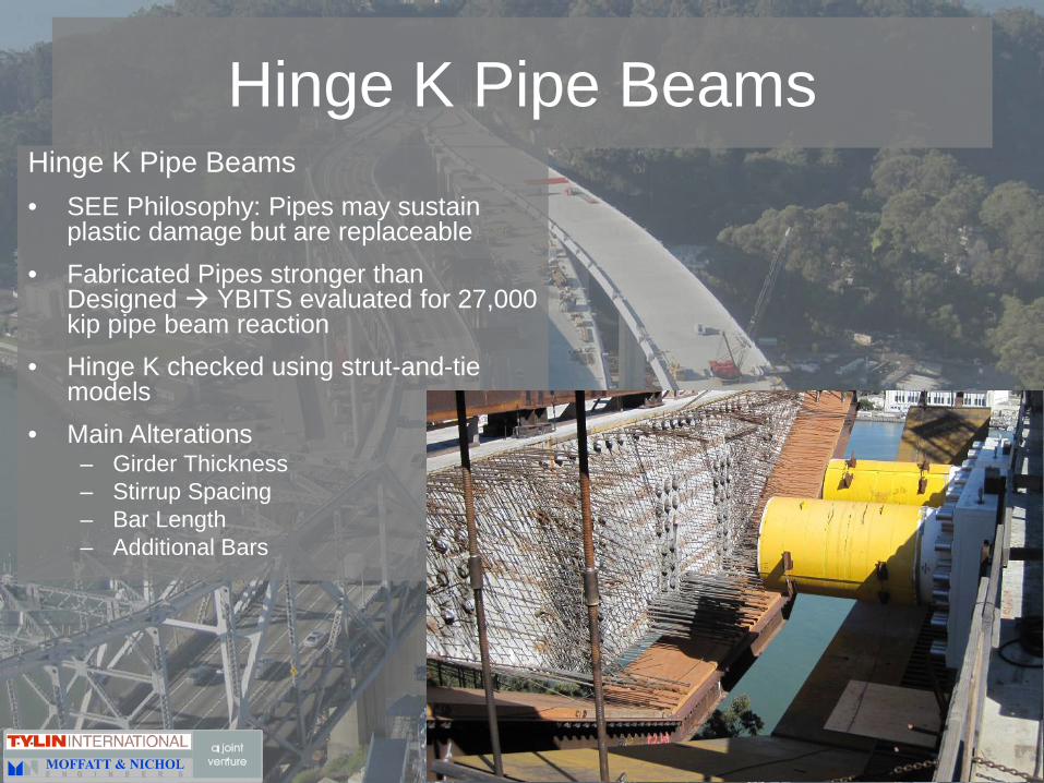
Hinge K Pipe BeamsHinge K Pipe Beams• SEE Philosophy: Pipes may sustain
plastic damage but are replaceable• Fabricated Pipes stronger than
Designed YBITS evaluated for 27,000 kip pipe beam reaction
• Hinge K checked using strut-and-tie models
• Main Alterations– Girder Thickness– Stirrup Spacing– Bar Length– Additional Bars

Hinge K Rebar – A Partnering Approach
Challenges of Hinge K Rebar Placement• Time• Space• Density of Rebar
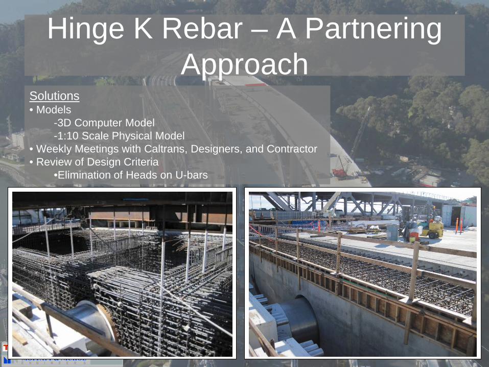
Solutions• Models
-3D Computer Model-1:10 Scale Physical Model
• Weekly Meetings with Caltrans, Designers, and Contractor• Review of Design Criteria
•Elimination of Heads on U-bars
Hinge K Rebar – A Partnering Approach

Hinge K Rebar Placement
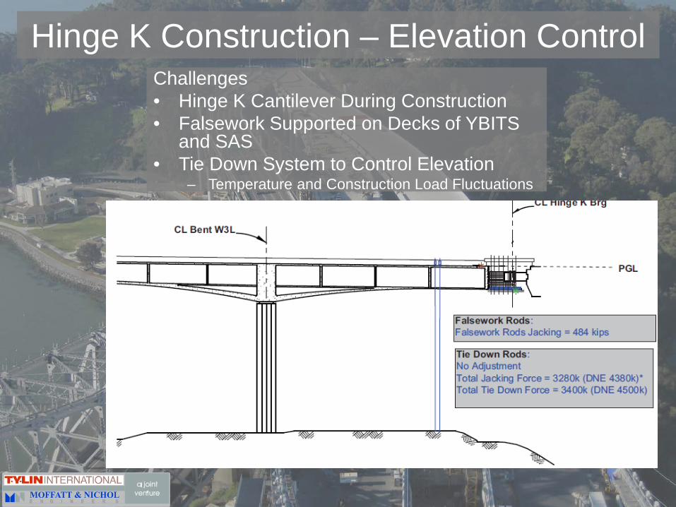
Hinge K Construction – Elevation ControlChallenges• Hinge K Cantilever During Construction• Falsework Supported on Decks of YBITS
and SAS• Tie Down System to Control Elevation
– Temperature and Construction Load Fluctuations
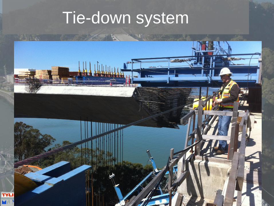
Tie-down system
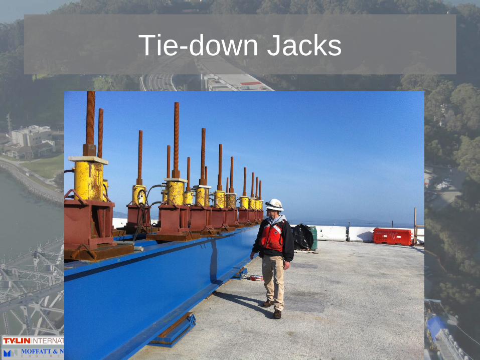
Tie-down Jacks
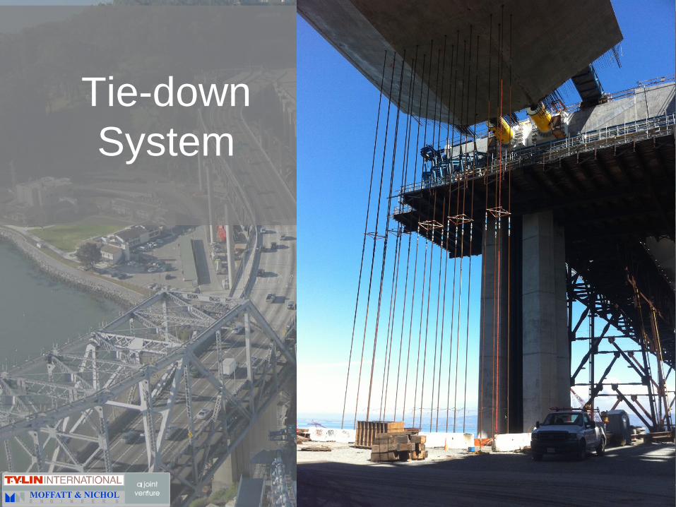
Tie-down System

Hinge K Construction- Elevation Control• Continuous Tie-Down Force Monitoring• Temperature Monitoring• Survey taken weekly and for major construction steps• Computer Models Updated Weekly

Conclusions for Hinge K
• Dynamic dissimilarities of YBITS & SAS• Designed-in a “capacity protected” failure
mode at hinge• Accelerated, zero-tolerance schedule for
Hinge K rebar placement• Hinge K Cantilever Elevation Control