design and simulation model for compensated and optimized...
TRANSCRIPT

International Journal of Advanced Research in Computer Engineering & Technology (IJARCET)
Volume 3 Issue 12, December 2014
ISSN: 2278 – 1323 All Rights Reserved © 2014 IJARCET
4216
Abstract— Advances in microwave solid state devices have
simulated interest in the integration of the microwave circuits.
Microstrip lines are being considered as viable candidates for
microwave communication and other applications. Microstrip
due to its various design advantages is particularly very
attractive. This creates the need for accurate modeling and
simulation of microstrip transmission lines. Virtually all
practical distributed circuits must contain discontinuities as
straight uninterrupted lines would be of little engineering use.
Microstrip discontinuities such as crossings, T-junctions, bends
and impedance steps are elements of many complex microstrip
circuits like filters, power dividers, ring couplers, and
impedance transformers. Therefore knowledge of exact
reflection and transmission properties in dependence on
frequency is of great importance. A simulation model is
presented here for analyzing the T-junctions in microstrip lines
through Sonnet Software at low frequencies (below 10 GHz).
The parameters of microstrip lines are determined from the
empirical formulae which are based on full wave analysis. The
simulation work has been performed on Alumina substrate. The
T-junctions are simulated and S-parameters hence calculated
show the transmission properties of the discontinuity and their
frequency dependency. The T-junction is also compensated to
get better transmission properties, and optimized which gives
important results for designing desired frequency microwave
circuits.
Index Terms— Full wave analysis, Microstrip line,
Microstrip discontinuities, T-junctions, Steps in width, Sonnet
Software, Substrate permittivity and S-parameters.
I. INTRODUCTION
In Microwave integrated circuits (MICs), the transmission
structure should be planar in configuration i.e. the
characteristics of the element can be determined by the
dimensions in a single plane. As for example, in a microstrip
line on a dielectric substrate the width can be adjusted to
control its impedance. The commonly used different types of
printed transmission lines for MICs are microstrip line, strip
line, suspended strip line, slot line, coplanar waveguide and
fin line, as shown in Fig. 1. Microstrip line is one of the most
popular lines in a transmission structure, mainly due to the
fact that the mode of propagation in a microstrip is almost
TEM [1]. The physical structure of a microstrip is shown in
the Fig. 2.
Manuscript received Dec,2014
Dr. Alok Kumar Rastogi, Department of Physics & Electronics,
Institute for Excellence in Higher Education, Bhopal, India, 9425004984.
Munira Bano, Department of Physics & Electronics, Institute for
Excellence in Higher Education, Bhopal, India, 9893320310.
Shanu Sharma, Department of Physics & Electronics, Institute for
Excellence in Higher Education, Bhopal, India, 9893809894.
Fig.1. Various Planar Transmission Line Structures
Fig.2. Physical & Constructional view of Microstrip line
A. Microstrip Discontinuities
All practical distributed circuits, whether in waveguides,
coaxial lines or any other propagation structure, must
inherently contain discontinuities. A straight uninterrupted
length of transmission structure would be of little engineering
use, and in any case junctions are essential. Although such
discontinuities give rise to only very small capacitances and
inductances (often <0.1pF and <0.1nH) the reactance of these
become particularly significant at the high microwave and
millimeter wave frequencies. Many circuits such as filters,
mixers and oscillators involve several discontinuities. All
technologies whether based on hybrid MICs or MMICs
(Monolithic Microwave Integrated Circuits) inherently
involves transmission discontinuities [2]. Discontinuity
modeling is based upon equivalent capacitances and
Design and Simulation Model for Compensated
and Optimized T-junctions in Microstrip Line
Alok Kumar Rastogi, Munira Bano, Shanu Sharma

International Journal of Advanced Research in Computer Engineering & Technology (IJARCET)
Volume 3 Issue 12, December 2014
4217
ISSN: 2278 – 1323 All Rights Reserved © 2014 IJARCET
inductances. The following are several forms of
discontinuities emerging from circuit requirements:
a) Open circuits
b) Series coupling gaps
c) Short circuits through to the ground plane
d) Step width changes
e) T & cross junctions
The T-junctions is perhaps the most important
discontinuity in a microstrip as it is found in most circuits
such as impedance networks, stub filters and branch line
couplers. A microstrip T-junction and its equivalent circuit
are shown in the Fig.3.
Fig. 3. Microstrip T-junction and its Equivalent Circuit
The T-junction discontinuity compensation is much more
difficult than right angled bends and steps in width
discontinuity compensation techniques. The T-junctions can
be compensated by adjusting the lengths of the three
microstrip lines forming the junction.
Various approaches have been made to calculate the
equivalent circuits for discontinuities. Oliner [3] used
Babinet‘s principle to describe stripline discontinuities,
Silvester and Benedek [4]-[6], and Stouten [7] calculated the
capacitances of microstrip discontinuities, and Gopinath and
Silvester [8], Gopinath and Easter [9], and Thomson and
Gopinath [10] computed the inductive elements of the
equivalent circuits. All the methods described in these papers
are based on static approximations, and therefore are valid
with sufficient accuracy only for low frequencies.
II. MICROSTRIP SYNTHESIS
In actual design of microstrip, one wishes to determine the
width ‗w‘ required to obtain specified characteristic
impedance ‗Z0‘ on a substrate of known permittivity ‗εr‘ and
thickness ‗h‘. This operation is called synthesis. Various
researchers have reported formulas for microstrip
calculations [11], [12]. Owens [13] carefully investigated the
ranges of applicability of many of the expressions given by
Wheeler, comparing calculated results with numerical
computations. The closed formulas are highly desirable as
they are accurate and fast. CAD algorithms can be
implemented with these formulas of Edward & Steer [14].
A. Synthesis Formula
For given Z0 and frequency:
In case of narrow strips i.e. when
Z0 > (44 - εr) Ω
1
'
'
exp4
1
8
exp
H
H
h
w
…… (1)
where
4ln
1
2ln
1
1
2
1
9.119
)1(20'
rr
rrZH
…… (2)
and
2
'
4ln
1
2ln
1
1
2
11
2
1
rr
rreff
H
(3) …… (3)
where 'H is given by equation (2) or alternatively as a
function of h
wfrom equation (1)
2164ln
2
'
w
h
w
hH
…… (4)
For microstrip line on Alumina, this expression appears
to be accurate to 2.0 % over the impedance range
508 0Z
when h
w and r are given:
2164ln
)1(2
9.1192
0w
h
w
hZ
r
…… (5)
III. SIMULATION
Sonnet Software [15] is commercial Software which
provides solutions for high frequency electromagnetic
analysis. This Em simulation software is used for design and
analysis for high frequency microstrip circuits. The analysis
engine of Sonnet Suite®, Em is appropriate for a wide range
of 3D planar structures. Via capabilities allow the analysis of
air bridges, wire bonds, spiral inductors, wafer probes, and
internal ports as well as for simple grounding.
IV. RESULTS AND DISCUSSION
The computations described in this paper were performed
on an alumina substrate, relative permittivity (εr = 9.9), loss
tangent (tan δ = 1×10⁻⁴
) and height of the substrate (h = 0.5
mm), through Sonnet Software [15]. Then from the synthesis
formula equation (1) and (2), we get approximate value for
the width of microstrip line w = 0.5 mm. Microstrip
T-junction is drawn in Sonnet with known height ‗h‘, width
‗w‘, and relative permittivity of Alumina substrate (εr).
International Journal of Advanced Research in Computer Engineering & Technology (IJARCET)
Volume 3 Issue 12, December 2014
ISSN: 2278 – 1323 All Rights Reserved © 2014 IJARCET
4218
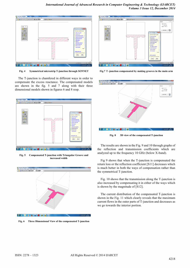
Fig. 4 Symmetrical microstrip T-junction through SONNET
The T-junction is chamfered in different ways in order to
compensate the excess reactance. The compensated models
are shown in the fig. 5 and 7 along with their three
dimensional models shown in figures 6 and 8 resp.
Fig. 5 Compensated T-junction with Triangular Groove and
increased width
Fig. 6 Three Dimensional View of the compensated T-junction
Fig.7 T -junction compensated by making grooves in the main arm
Fig. 8 3D view of the compensated T-junction
The results are shown in the Fig. 9 and 10 through graphs of
the reflection and transmission coefficients which are
analyzed up to the frequency 10 GHz (below X-band).
Fig 9 shows that when the T-junction is compensated the
return loss or the reflection coefficient [S11] decreases which
is much better in both the ways of compensation rather than
the symmetrical T-junction.
Fig. 10 shows that the transmission along the T-junction is
also increased by compensating it in either of the ways which
is shown by the magnitude of [S12].
The current distribution of the compensated T-junction is
shown in the Fig. 11 which clearly reveals that the maximum
current flows in the outer parts of T-junction and decreases as
we go towards the interior portion.

International Journal of Advanced Research in Computer Engineering & Technology (IJARCET)
Volume 3 Issue 12, December 2014
4219
ISSN: 2278 – 1323 All Rights Reserved © 2014 IJARCET
Fig 9 Reflection Coefficient Vs Frequency for Microstrip
T-junction and its compensated models
Fig 10 Transmission Coefficient Vs Frequency for Microstrip
T-junction and its compensated models
Fig. 11 Current Density of the compensated T-junction along with
scale depicting the value
The compensated T-junction is then optimized in order to
get better results as shown in Fig. 12. The optimization tool in
Sonnet is used to see the variation in return loss when the
width of the T-junction is varied. The results of optimization
are shown in the Fig. 13. As it can be seen from the figure that
the minimum return loss is obtained when the compensated
width of the line is 0.9 mm. If the width is changed from this
value (either increased or decreased), the reflection increases
hence increasing the return loss. Thus the graph here supports
our calculations as well as simulation. Thus after optimizing
we can fix the width of the T-junction to make our return loss
minimum and proper transmission of waves.
Fig. 12 The compensated model used for optimization with width
as the variable
Fig. 13 Results of Optimizing the T-junction
V. CONCLUSION
As soon as a transmission line is used in practical circuits,
there will be no longer a continuous cross-section geometry,
but there will be changes brought about by the joining
together of lines, the changing of characteristic impedance or
propagation direction and the connection to various loads.
A method is described for calculating the dynamical
properties of various microstrip T-junctions. The elements of
scattering matrix (i.e. reflection and transmission
coefficients) give important results for lower frequencies.
CAD models are used to compensate the T-junctions for
better efficiency at low frequencies. Sonnet Software is used
to optimize the width of the compensated T-junction which
gives a way to lower the return loss in the circuit.
The methods described in this paper may lead to the
possibility of studying compensation methods for power

International Journal of Advanced Research in Computer Engineering & Technology (IJARCET)
Volume 3 Issue 12, December 2014
ISSN: 2278 – 1323 All Rights Reserved © 2014 IJARCET
4220
dividers and similar circuits.
REFERENCES
[1] K. C. Gupta, Ramesh Garg, I. J. Bahl, ―Microstrip Lines and Slot
Lines‖, Artech House Inc. Washington, 1979.
[2] Wheeler, H.A., ―Transmission Line Properties of a Strip on a Dielectric
Sheet on a plane‖, IEEE Trans. Vol. MTT-25, 1977, pp 631-647.
[3] A. A. Oliner, ―Equivalent circuits for discontinuities in balanced strip
transmission line‖, IEEE Trans. Microwave Theory Tech. (Special
Issue on Symp. On Microwave Strip Circuits), Vol. MTT-3, pp.
134-143, Nov. 1955.
[4] P. Silvester and P. Benedek, ―Equivalent capacitances of microstrip
open circuits‖, IEEE Trans. Microwave Theory Tech., Vol. MTT-20,
pp. 511-516, Aug. 1972.
[5] P. Benedek and P. Silvester, ―Equivalent capacitances of microstrip
gaps and steps‘, IEEE Trans. Microwave Theory Tech., Vol. MTT-20,
pp. 729-733, Aug. 1972.
[6] P. Silvester and P. Benedek, ―Microstrip Discontinuity capacitances
for right angled bends, T-junctions and crossings‖ IEEE Trans.
Microwave Theory Tech., Vol. MTT-21, pp. 341-346, May 1973.
[7] P. Stouten, ―Equivalent Capacitances on T-junctions‖, Electron. Lett.,
vol. 9, pp. 552-553, Nov. 1973.
[8] A. Gopinath and P. Silvester, ―Calculation of inductance of finite
length strips and its variation with frequency‖, IEEE Trans.
Microwave Theory Tech., Vol. MTT-21, pp. 380-386, June 1973.
[9] A. Gopinath and B. Easter, ―Moment method of calculating
discontinuity inductance of microstrip right angled bends‖, IEEE
Trans. Microwave Theory Tech.(Short Papers), Vol. MTT-22, pp.
880-883, Oct. 1974.
[10] A. Thompson and A. Gopinath, ―Calculation of microstrip
discontinuity inductance‖, IEEE Trans. Microwave Theory Tech., Vol.
MTT-23, pp. 648-655, Aug. 1975.
[11] Wheeler, H. A., ―Transmission-line properties of parallel wide strips by
a conformal mapping approximation,‖ IEEE Trans. Microwave Theory
and Tech., Vol. 12, May 1964.
[12] Wheeler, H. A., ―Transmission-line properties of parallel strips
separated by a dielectric sheet,‖ IEEE Trans. Microwave Theory and
Techn., Vo1.13, , Mar. 1965, pp. 172-185.
[13] Owens, R. P., ―Accurate analytical determination of quasi-static
microstrip line parameters,‖ The Radio and Electronic Engineer, 46,
No. 7, July 1976, pp. 360-364.
[14] T.C. Edwards, M.B. Steer, ―Foundations of Inter connect and
Microstrip Design‖, John Wiley & Sons Ltd.
[15] High Frequency Electromagnetic Software SONNET-13.56 User
guide.
Dr. Alok Kumar Rastogi Presently Dr. Alok Kumar
Rastogi is Professor & Head, Department of Physics & Electronics at
Institute for Excellence in Higher Education Bhopal. He did M.Phil
(Physics) from the Department of Physics & Astrophysics, University of
Delhi in 1984 and completed his Ph.D. Degree in Electronics Engineering
from Bhopal University, Bhopal in the year 1990. He received Young
Scientist Award for his excellent research work in the field of Microwave
Communication in the year 1987. He received EC Post doctoral “Marie
Curie” Fellowship, awarded by European Commission, Brussels, Belgium
and Ministry of Science and Technology, DST, New Delhi to carry out
research work in University of Bradford, England (U.K.) in the year 1995.
Indo-Russian Long Term Project (ILTP) was awarded to him in 1996 by
Russian Academy of Science, Moscow and DST, New Delhi for the period of
three years. He completed various Major and Minor Research Projects
awarded by UGC, New Delhi. UGC New Delhi awarded him several
research projects to carry out research work in the field of microwave
communication. He is having professional affiliation with various national
organizations. He is Fellow of IETE and life member of IE, IAPT, ISCA,
ISTE, PSSI etc. Seven Ph.D. have been awarded under his supervision in
the field of microwave communication and five candidates are perusing
research work for their Ph.D. degree under his guidance. About 100 research
papers have been published in the reputed International and National
Journals. More than 20 International conferences attended and visited many
countries (U.S.A., U.K., Belgium, Holland, Luxemburg, Germany, Japan
and France) to present research papers in the International Conferences. In
the year 2009 UGC, New Delhi nominated Dr. Rastogi to visit Mauritius
under IVth UGC – TEC consortium agreement to deliver series of lectures at
University of Mauritius for the period of three months. Dr. Rastogi
established “Microwave and Optical Fiber communication Study and
Research Laboratory” in the Institute for Excellence in Higher Education,
Bhopal under Mission Excellence Scheme of MPCST, Bhopal in the year
2011.
Ms. Munira Bano she is currently undertaking research
in microwave communication at Institute for Excellence in Higher
Education, Bhopal under the guidance of Dr. Alok Kumar Rastogi. She was
awarded M.Phil (Physics) in 2007 by Barkatullah University, Bhopal. She is
a Senior Research Fellow under the Maulana Azad National Fellowship
Programme of UGC. She has published many research papers in various
scientific journals. She has also participated in numerous national and
international conferences. She has been awarded best research paper at
International Conference on Interdisciplinary Research in Engineering,
Management, Pharmacy and Sciences held at Sagar Institute of Research &
Technology Bhopal from 20th-23rd Feb. 2014.
Ms. Shanu Sharma Presently she is working as a lecturer
in Institute for Excellence in Higher Education. She did M.Sc. Electronics in
2008 and M.Sc. Mathematics in 2010. She is persuing research work under
the guidance of Dr. Alok Kumar Rastogi in field of microwaves. She has
participated in many national and international conferences. She has
published many research papers in reputed journals.