design of an anti-lock regenerative braking system for a …ijae.iust.ac.ir/article-1-12-en.pdf ·...
TRANSCRIPT

Design of an Anti-Lock Regenerative Braking System for a ...14
International Journal of Automotive Engineering Vol. 1, Number 2, June 2011
1. INTRODUCTION
An important fuel saving element in hybrid electricvehicles (HEV) is the regenerative braking system(RBS), saving a considerable amount of energy duringthe brake of a vehicle [1]. The total energy dissipatedthrough braking during a typical urban area drive mayreach up to 34% of the total traction energy. In largecities, with frequent stops and lots of intersections,this portion may reach up to 80% [2]. During brakephase, the electric traction motor of an electric orhybrid electric vehicle can be easily controlled tofunction as a generator, converting some of the kineticenergy of the vehicle into electric energy. Therecovered energy can be stored in an electric energystorage system and subsequently used for thepropulsion, significantly reducing the vehicle's overallenergy consumption and exhaust emissions [3].Accordingly, a well-designed RBS can increase thedriving range of a HEV up to 16% [4], and enhancethe safety of HEV [5]. Nevertheless, a relativelylimited research has focused on the brake system forHEVs compared to powertrain technologydevelopment [6].
One advanced feature in braking system of modernvehicles is the anti-lock brake system (ABS). Lockingup of front and rear wheels can cause loss of vehiclestability and an increase in stopping distance. When a
wheel lock up is detected, the braking control systemreduces the pressure applied to the brake actuators andbrings the wheel back to spinning. In conventionalvehicles, ABS is generally achieved through thecontrol of hydraulic or pneumatic pressure which isfed to the wheel brake actuators.
In electric vehicles and series HEVs, where electricmotor (EM) is the only source of traction of vehicle,ABS can be achieved through controlling the EM dueto its desirable response time, which is faster than theresponse time of mechanical systems [7].Implementation of mechanical ABS (i.e. ABS throughthe mechanical actuators) as the primary brakingsystem along RBS in HEVs would greatly increase thecomplexity of braking system and also themanufacturing cost of electric vehicles. In addition, bythe activation of mechanical ABS, the regenerativebrake system as the secondary braking system inHEVs is typically inactivated which substantiallydecreases the amount of recovered energy. Combineduse of anti-lock and regenerative braking systems inHEVs can greatly reduce these complexities and hasbeen the focus of few recent studies [8-11]. Gao andEhsani [8] have proposed a controller for EM bycombining ABS and RBS functions. In their study,they assumed that the vehicle speed and road surfaceconditions are known parameters during braking.These assumptions are not realistic and dramatically
Design of an Anti-Lock Regenerative Braking System for aSeries Hybrid Electric Vehicle
M. M. Tehrani1,*, M. R. Hairi -Yazdi1, B. Haghpanah-Jahromi2, V. Esfahanian1, M. Amiri1 and
A. R. Jafari1
1 Mechanical Engineering Department, University of Tehran, Tehran, Iran2 Mechanical & Industrial Engineering Department, Northeastern University, Boston, Massachusetts, USA
* Email: [email protected]
Abstract
In this paper, an adaptive rule based controller for an anti-lock regenerative braking system (ARBS) of a series hybrid
electric bus (SHEB) has been proposed. The proposed controller integrates the regenerative braking and wheel anti-
lock functions by controlling the electric motor of the hybrid vehicle, without using any conventional mechanical anti-
lock braking system. The performance of the proposed system is evaluated by a comprehensive vehicle dynamics
model in MATLAB/Simulink. Using the designed ARBS, the braking and regenerative performances of SHEB have
significantly improved in slippery roads while the slip ratios are kept between 0.15 and 0.20.
Keywords: Anti-Lock Regenerative Braking System, Series Hybrid Electric Vehicle, Slip Control, Adaptive Rule BasedController
Dow
nloa
ded
from
ijae
.iust
.ac.
ir at
19:
42 IR
DT
on
Frid
ay J
une
1st 2
018

15
International Journal of Automotive Engineering Vol. 1, Number 2, June 2011
M. M. Tehrani, M. R. Hairi -Yazdi, B. Haghpanah-Jahromi, V. Esfahanian,M. Amiri and A. R. Jafari
compromise the performance of braking system indifferent road conditions. Mutoh et.al [9] studied thesafety of EVs during driving and braking of specialEVs with the front and rear wheel independent drivingcapability. They showed that electric braking controlsystem can prevent vehicles from experiencing wheellock and can improve the riding comfort regardless ofdriver’s brake pedal application. Recently, animplementation of ABS for the parallel hybrid electricvehicle with combining anti-lock regenerative brakingsystem and anti-lock hydraulic braking system wasproposed [10-11].
The prediction of wheel lock up is of greatimportance in the design of ABS. In industrial ABSs,the angular velocities of the wheels are measured withsensors and are directly utilized to determine the riskand prevent the wheel locked-up before it happens[12]. In some recent studies, the slip ratios of thewheels have been estimated from the data from wheelangular velocity sensor and utilized in ABS controller[13-14]. In these systems, ABS is aimed to control thewheel slip at an optimum value that can providemaximum traction force during heavy braking [15].The proposed controller utilizes wheels slip ratios forpredicting the wheel lock up situation. In order tocalculate the wheel slip ratio, the absolute velocity ofthe vehicle other than the linear speeds of wheelsduring braking, is needed. The absolute vehicle speedduring braking is estimated from the angular speed ofthe wheels and the amount of braking torque.
In this paper, a controlling scheme of an anti-lockregenerative braking system (ARBS) for a SHEB hasbeen proposed. The proposed system utilizes theinborn advantage of the electric vehicle by controllingthe braking torque applied to the wheels through theEM, which operates as an electric generator duringbraking. This system can handle the vehicle instabilityand steerability issues on slippery roads withoututilizing additional conventional costly hardware suchas hydraulics or pneumatics ABS apparatus. Theproposed system contains a speed observer modulethat can estimate the absolute velocity of the vehicleduring braking from the values of applied brakingtorque and acceleration of the wheels. The data fromthis module is used to restrict the slip ratio of thewheels between 0.15 and 0.20. The ARBS has beenshown to effectively improve the braking performanceand fuel consumption of SHEB in different roadconditions.
Abbreviation
ABS Anti-lock brake systemARBS Anti-lock regenerative braking systemEM Electric motorHEV Hybrid electric vehiclesRBS Regenerative braking systemSHEB Series hybrid electric busSoC State of Charge of the battery
Nomenclature
b Cycle number of ABS processF Braking forceg Acceleration of gravityh Center of gravity heightJ Wheel moment of inertiaLa Distances of the center of gravity from front
axle Lb Distances of the center of gravity from rear
axleM Mass of the vehicleN Normal force of the wheelR Radius of the wheelS Slip ratioS* Critical slip ratioT Braking torqueTdem Braking torque demandTmechbrake Mechanical braking torqueTreg Regenerative braking torqueTreg. Prev. Last value of regenerative braking
torque during ABSTT Total braking torqueV Vehicle speedVmin A limit value of vehicle speed for
deactivation of ABS(S) Adhesive coefficient between the road and
the wheel
p Peak value of adhesive coefficient
s Sliding value of adhesive coefficientAngular speed of the wheel
f Index of front wheelsr Index of rear wheels
2. MODELING
To evaluate the performance of the proposedbraking system, a comprehensive model of a serieshybrid electric bus (SHEB) is constructed in
µ µ
µ
Dow
nloa
ded
from
ijae
.iust
.ac.
ir at
19:
42 IR
DT
on
Frid
ay J
une
1st 2
018

Design of an Anti-Lock Regenerative Braking System for a ...16
International Journal of Automotive Engineering Vol. 1, Number 2, June 2011
MATLAB/Simulink. Figure 1, shows the schematicmap of hybrid drive-train of the SHEB, where RBScomponents are shaded in dark color. The brakesimulation module includes five main blocks ofvehicle and tire dynamics, EM dynamics, mechanicalbrake system, ARBS controller and speed observer asshown in Figure 2.
2. 1. Vehicle and Tire Dynamics
The block of vehicle and tire dynamics includesvehicle dynamics relations, tire dynamics relationsand road condition. Figure 3 shows a two wheel modelof HEV for braking studies, where the wind force, hill
climbing force and rolling resistance are neglected. Inthis figure, Ff and Fr are the braking forces acted onfront and rear wheels, respectively. M is the mass ofthe vehicle and g is acceleration of gravity. La, Lb andh are distances of the center of gravity from front axle,rear axle and center of gravity height, respectively.
The slip ratio, S, is defined as the relative differencebetween the vehicle speed and the linear wheel speed:
(1)
where V is the vehicle speed, is the angularspeed of the wheel and R is the radius of the wheel.
The traction forces, or braking forces in case of
VRVS ��
�
Fig. 1. Drive-train of the SHEB
Controller Dynamic Model
Speed Observer
Desired slip ratio
Observed slip ratio
Pedal position
+-
MechanicalBrake
RegenerativeBrake
Fig. 2. Comprehensive dynamics model
Dow
nloa
ded
from
ijae
.iust
.ac.
ir at
19:
42 IR
DT
on
Frid
ay J
une
1st 2
018

17
International Journal of Automotive Engineering Vol. 1, Number 2, June 2011
M. M. Tehrani, M. R. Hairi -Yazdi, B. Haghpanah-Jahromi, V. Esfahanian,M. Amiri and A. R. Jafari
braking, shown in Figure 3 can be expressed as:
(2)
where (S) is the adhesive coefficient between theroad surface and the tire which is a function of slipratio, S. Also, N is the normal force of the tire (f and rindices point to front and rear tires).
Neglecting wind force, rolling resistance, and hillclimbing force, the equation of the vehicle motion canbe expressed as:
(3)
The equation of the wheel motion can be expressedas:
(4)
where Jw is the wheel moment of inertia and Tm is
the total braking torque.The braking force is a function of the adhesive
coefficient between the tire and the roadway and isdetermined by the road surface condition and the slipratio. The typical variation of road adhesivecoefficients versus the wheel slip ratio is shown inFigure 4, [2]. The adhesive coefficient reaches its peakvalue ( p) near the critical slip ratio of S* for mostroad conditions. When the slip ratio is below S*,increasing the slip ratio can enhance the traction force.Once the slip ratio exceeds S*, the traction force willdecrease as a result of the decrease in adhesivecoefficients down to the sliding value ( s).
The adhesive coefficient in the lateral direction, akey factor in the stability and the steerability ofvehicle, increases by decreasing the slip ratio.Therefore, confining the slip ratio under the criticalslip ratio of S* guarantees the stability and thesteerability of vehicle.
2. 2. Electric Motor Dynamics
The block of EM Dynamics includes the EM,which functions as generator during braking, batteriesand brake resistor. EM is coupled to the rear wheels bydrive train. Figure 5 schematically illustrates theregenerative braking system components. Thepneumatic system is not shown in this figure.
Generator and traction performances of electricmotor are almost identical. The maximum torque andpower of EM is a function of the speed of EM asshown in Figure 6. In the vehicle under study, there aretwo coupled electric traction motors. The generator’sefficiency is defined as the ratio of output electricpower to input mechanical power. Efficiency map of
µ
µ
RFTdtdJ mw ����
)( rf FFdtdVM ���
µ
� �� � rrrr
ffff
NSF
NSF
��
��
�
�
Fig. 4. Road adhesive coefficients
Fig. 3. Two wheel model of vehicle
Dow
nloa
ded
from
ijae
.iust
.ac.
ir at
19:
42 IR
DT
on
Frid
ay J
une
1st 2
018

Design of an Anti-Lock Regenerative Braking System for a ...18
International Journal of Automotive Engineering Vol. 1, Number 2, June 2011
the generator is almost equal to efficiency map of EMin traction and is shown in Figure 7.
During braking, not only does locking of wheelscontribute to the increase of stopping distance, but italso lowers the amount of recovered energy. That isbecause in case of locking wheels, the rotational speedof connected EM becomes close to zero and themaximum amount of generator power of EMdecreases according to Figure 6.
Regenerated energy by EM is given to the batteries.Batteries store a portion of this energy according totheir limitations and free capacity, and the additionalenergy is dissipated in brake resistor. The batteries thatare utilized in the bus under study are 40 Ah lithium-polymer batteries. This series of batteries consists of168×3.7V battery cells. The internal resistance of eachbattery cell is approximately 2 mÙ. Changes in chargeof batteries due to the absorbed energy by generator
are expressed by the percentage of the State of Charge(SoC).
Through the block of EM dynamics, the amount ofabsorbed energy in batteries, subsequent changes inSoC and the amount of energy which is dissipated in
Fig. 6. Maximum EM braking torque and power in various shaft speeds
Fig. 7. Map of EM efficiency
Fig. 5. Regenerative braking system components
Dow
nloa
ded
from
ijae
.iust
.ac.
ir at
19:
42 IR
DT
on
Frid
ay J
une
1st 2
018

19
International Journal of Automotive Engineering Vol. 1, Number 2, June 2011
M. M. Tehrani, M. R. Hairi -Yazdi, B. Haghpanah-Jahromi, V. Esfahanian,M. Amiri and A. R. Jafari
the brake resistor are determined.
2. 3. Mechanical Brake System
Mechanical braking system of the SHEB understudy is a pneumatic braking system. Pneumaticbraking pressure which acts both on front and rearwheels is a function of brake pedal displacement, asshown in Figure 8. Total braking torque of rear wheelsis the sum of generator braking torque that is providedby EM and the mechanical (pneumatic) brakingtorque. The pneumatic braking torque is determinedby the pneumatic braking pressure and specificationsof the wheel braking actuators.
The mechanical brake system of SHEB is onlycontrolled by brake pedal displacement applied by thedriver. There is no additional system (such as ABS) togenerate dynamics commands to affect the mechanicalbrake forces. Therefore, if the angular displacement ofbrake pedal is constant in a test cycle, the pneumaticbrake pressure and force are constant.
3. BRAKE CONTROLLER
The inputs of controller unit are front and rearwheels slip ratios and brake pedal displacement. Thebrake control strategy, defined in the brake controllermodule, determines the regenerative torque that isapplied to the rear wheel during braking.
In brake pedal angles below six degrees(mechanical brake is inactive according to Figure 8),the controller increases regenerative braking torquelinearly with brake pedal angle to simulate the retarderfunction in conventional city bus. The retarder actssimilar as an engine brake in conventional heavy-dutyvehicles. The controller applies available regenerativebraking force (maximum braking force produced bythe electric motor) when mechanical brake is activatedin brake pedal angle of six degrees. This is verysimilar to “the series braking system with optimalenergy recovery” [2].
If the wheels are predicted to lock up by controller,the controller reduces and controls the regenerativebraking torque allowing the wheels to reach theiroptimum slip ratio. To predict rear wheel locking upand to find semi-optimal braking torques, slip ratiosare considered. If the slip ratio of rear (driven) wheelis below 0.18 the driver desired braking torque isapplied to the wheels, if the slip ratio of the rearwheels exceeds 0.18 the brake controller decreases theEM braking torque to let the wheels accelerate. Whenlock up risk has removed, the braking torque isreapplied, lower than the previous amount that had ledto wheel lock up. By this procedure, the semi-optimalbraking torque associated with the near optimum slipratio of 15-20% is determined in a few steps. If all theregenerative braking torque is removed and wheel isstill in lock mode, EM may change its state from
Fig. 8. Pneumatic braking pressure versus brake pedal displacement
Dow
nloa
ded
from
ijae
.iust
.ac.
ir at
19:
42 IR
DT
on
Frid
ay J
une
1st 2
018

Design of an Anti-Lock Regenerative Braking System for a ...20
International Journal of Automotive Engineering Vol. 1, Number 2, June 2011
generator to traction motor to overcome mechanicalbraking torque, letting the wheel to accelerate.
The decision algorithm of developed adaptive rulebased brake controller is illustrated in Figure 9.
As shown in Figure 9, these main rules are effectivein the decision making algorithm of developed brakecontroller.• If the vehicle speed (V) is zero, the brake
process will be halted.• If the vehicle speed (V) is less than 5 km/h
(Vmin), ABS is deactivated.• If the ABS is deactivated, regenerative brake
torque (Treg) will be equal to the brake torquedemand (Tdem) which is specified by brakepedal.
• The last value of regenerative braking torqueduring ABS process will be stored in Treg. Prev.
• In the first cycle that ABS is activated and the“increase” is on, regenerative braking torquewill be 20% less than Treg. Prev. . In the othercycles, if cycle number (b) is an integer factor
of 10, Treg will be 1% greater than Treg. Prev. . Inthe other cases, Treg will be equal to Treg. Prev. .
• If the slip ratio of rear wheel is greater than20%, ABS is activated, the “decrease” is turnedon, the “increase” is shut off, and cycle numberof ABS process (b) is restored to zero.
• If the slip ratio of rear wheel is not greater than20% and ABS is activated, the brake torquedemand (Tdem) is compared to Treg. Prev. . If Tdem
is greater, the “decrease” is turned off and the“increase” is turned on. Otherwise, ABS isdeactivated.
There are two adaptive modes to detect the roadsurface condition in the decision algorithm ofdeveloped brake controller. If the regenerative brakingtorque is greater than adhesive capacity of roadsurface (the slip ratio is greater than 20%), the newregenerative braking torque is 20% less than theprevious one (the “decrease” mode). If theregenerative braking torque is less than adhesivecapacity of road surface (the slip ratio is not greaterthan 20%) and Treg. Prev. is less than demand torque(Tdem), the regenerative braking torque becomes 1%greater than the previous one in every 10th cycles ofABS (the “increase” mode).
These two adaptive modes of developed brakecontroller can detect the static or the dynamicscondition of adhesive capacity of road surface. In theresult section, the results from some performance testsare presented to show the capability of these adaptivemodes.
4. SPEED OBSERVER
The proposed speed observer unit is designed tocalculate the absolute velocity of the vehicle from thevalues of applied torque to wheels and wheelsacceleration. To compute the vehicle’s absolutevelocity, the deceleration of vehicle is calculated bythe derived vehicle dynamic formulas and thenintegrated.
First consider the situation where neither the frontwheels nor the rear wheels are locked ( f >0 and r >0).From relation (4), the total braking torque acting onvehicle is [2]:
(5)
Therefore, the deceleration of vehicle becomes:
fffrrrfr TJTJFFR ����� �� ��)(
Fig. 9. Flow Chart of Developed Brake Controller
Dow
nloa
ded
from
ijae
.iust
.ac.
ir at
19:
42 IR
DT
on
Frid
ay J
une
1st 2
018
21
International Journal of Automotive Engineering Vol. 1, Number 2, June 2011
M. M. Tehrani, M. R. Hairi -Yazdi, B. Haghpanah-Jahromi, V. Esfahanian,M. Amiri and A. R. Jafari
(6)
Assuming that the vehicle initial absolute speed andinitial rear and front wheels linear speeds are V0, V0rand V0f, respectively, the absolute vehicle velocity canbe obtained by integration as:
(7)
where TT is the total braking torque of front andrear wheels.
In this case, the adhesion coefficients of front andrear wheels can be calculated as:
(8)
(9)
Now, consider the situation where only rear wheelsare locked ( ). It can be shown that the brakingforce acting on rear wheels is obtained by [2]:
(10)
where . Thus, the net braking force acting on
vehicle is:
(11)
The vehicle deceleration can be calculated fromrelation (3). By integrating the vehicle decelerationover time, assuming that the initial value of absolutevehicle speed and initial front wheels speed at thebeginning of this situation are V0 and V0f, the vehicleabsolute velocity can be obtained as:
(12)
For the situation where only front wheels arelocked, in a similar way the vehicle absolute velocityis obtained as:
(13)� �
�
�
�
���
MR
dtTVV
MRJ r
rrr
.02
�
�
��
��� hL
LgdthLL
VVff
bf0 ��
�
� �
�
�
�
���
MR
dtTVV
MRJ f
fff .
02
��
��� hL
LgdthLL
VVrr
ar0 ��
�
�
� �
��
��
���
RT
RJ
hLL
hLMgLFF f
ff
rr
arfr �
���
�
)(MgF
hLhLMgF f
ar
rr �
��
��
0�r�
� � LMggVhLRJT
NF
ga
rrr
r
rr �
�
����
���
�
� � LMggVhLRJT
NF
ga
rrr
r
rr �
�
����
���
�
� � � �fff
rrr VV
MR
JVV
MRJVV 02020 �����
MR
dtTT� .
RMTTJJ
dtdV frffrr ���
���� ��
Read:V0, V0r and V0f
Read:Vr and Vf
Vr == 0Vf == 0 Vf == 0Yes
No
Both Locked:Eq. (16)
Yes
Rear Locked:Eq. (13)
No
Front Locked:Eq. (14)
No locking:Eq. (8)
YesNo
Read: Treg, Tmech_brake_r
and Tmech_brake_f
µr and µf :Eq. (9) and (10)
Vehicle Speed
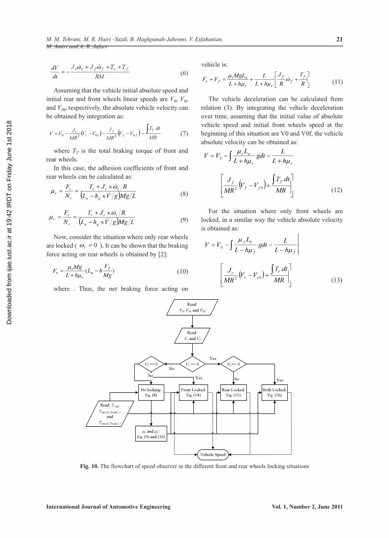
Fig. 10. The flowchart of speed observer in the different front and rear wheels locking situations
Dow
nloa
ded
from
ijae
.iust
.ac.
ir at
19:
42 IR
DT
on
Frid
ay J
une
1st 2
018
22
International Journal of Automotive Engineering Vol. 1, Number 2, June 2011
In the case where both rear and front wheels arelocked, it can be shown that vehicle decelerationbecomes:
(14)
Assuming that the initial value of vehicle absolutevelocity at the beginning of this situation is V0, thevehicle absolute velocity is obtained by integration,as:
(15)
In the last three cases where the adhesioncoefficients are required, the average values ofrelations (9) and (10) are utilized. These values aredetermined before any of wheels are locked. If the
anti-lock algorithms can restore the system from thelocking to the normal condition, the adhesioncoefficients are recalculated for next locking states.
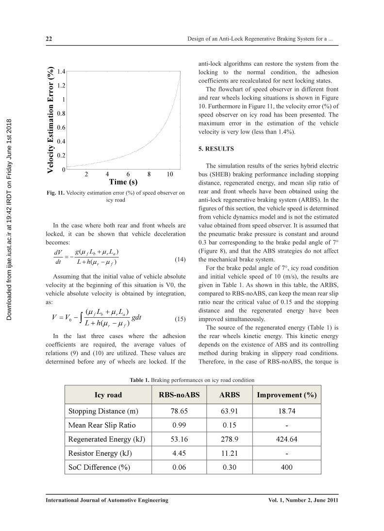
The flowchart of speed observer in different frontand rear wheels locking situations is shown in Figure10. Furthermore in Figure 11, the velocity error (%) ofspeed observer on icy road has been presented. Themaximum error in the estimation of the vehiclevelocity is very low (less than 1.4%).
5. RESULTS
The simulation results of the series hybrid electricbus (SHEB) braking performance including stoppingdistance, regenerated energy, and mean slip ratio ofrear and front wheels have been obtained using theanti-lock regenerative braking system (ARBS). In thefigures of this section, the vehicle speed is determinedfrom vehicle dynamics model and is not the estimatedvalue obtained from speed observer. It is assumed thatthe pneumatic brake pressure is constant and around0.3 bar corresponding to the brake pedal angle of 7°(Figure 8), and that the ABS strategies do not affectthe mechanical brake system.
For the brake pedal angle of 7°, icy road conditionand initial vehicle speed of 10 (m/s), the results aregiven in Table 1. As shown in this table, the ARBS,compared to RBS-noABS, can keep the mean rear slipratio near the critical value of 0.15 and the stoppingdistance and the regenerated energy have beenimproved simultaneously.
The source of the regenerated energy (Table 1) isthe rear wheels kinetic energy. This kinetic energydepends on the existence of ABS and its controllingmethod during braking in slippery road conditions.Therefore, in the case of RBS-noABS, the torque is
��
��� gdt
hLLL
VVfr
arbf
)()(
0 ����
)()(
fr
arbf
hLLLg
dtdV
������
���
2 4 6 8 100
0.2
0.4
0.6
0.8
1
1.2
1.4
Time (s)
Vel
ocity
Est
imat
ion
Err
or (%
)
Fig. 11. Velocity estimation error (%) of speed observer onicy road
Icy road RBS-noABS ARBS Improvement (%)
Stopping Distance (m) 78.65 63.91 18.74
Mean Rear Slip Ratio 0.99 0.15 -
Regenerated Energy (kJ) 53.16 278.9 424.64
Resistor Energy (kJ) 4.45 11.21 -
SoC Difference (%) 0.06 0.30 400
Table 1. Braking performances on icy road condition
Design of an Anti-Lock Regenerative Braking System for a ...
Dow
nloa
ded
from
ijae
.iust
.ac.
ir at
19:
42 IR
DT
on
Frid
ay J
une
1st 2
018

23
International Journal of Automotive Engineering Vol. 1, Number 2, June 2011
M. M. Tehrani, M. R. Hairi -Yazdi, B. Haghpanah-Jahromi, V. Esfahanian,M. Amiri and A. R. Jafari
constant and high while the wheel is locked and theangular velocity is zero. For that reason, the kineticenergy of the wheel is very low and the total recoveredenergy is reduced. In the case of ARBS, the torque iscontrolled based on the value of the slip ratio. In thiscase, the wheels constantly kept away from beinglocked and the energy recovery would significantlyimprove.
Figures 12-13 illustrate the vehicle speed and theequivalent rear (driven) wheels speed during braking.As shown in these figures, the rear wheels are lockedin the RBS-noABS strategy (Figure 12), while theARBS can control the electric motor braking torque toprevent rear wheels from locking (Figure 13).
In Figure 14, the rear wheels slip ratio versus time
charts are presented and compared on icy roadcondition. The ARBS is successful in preventingvehicle instability by keeping the slip ratio very closeto optimal value of 0.15 and consequently increasingthe lateral adhesive coefficient (see Figure 4).
Figure 15 shows the EM regenerative brakingtorque during braking. The regenerative brakingtorque of EM is constant in the conventional SHEB(“RBS-noABS”). The adaptive behavior (including“increase” and “decrease” modes) of EM brakingtorque in the ARBS can make the EM braking torquereach the orders of optimal regenerative brakingtorques in the first two seconds. After this stage, theadaptive modes are repeated to detect possible suddenchanges of road condition.
0 5 10 150
0.2
0.4
0.6
0.8
1
Time (s)
Slip
Rat
io
noABSARBS
Fig. 14. Rear wheels slip ratio comparison on icy road
0 2 4 6 8 10 12 14 160
2000
4000
6000
8000
10000
Time (s)
Tor
que
(N.m
) RBS-noABSARBS
Fig. 15. Regenerative EM torque on icy road
0 2 4 6 8 10 12 14 160
2
4
6
8
10
Time (s)
Spee
d (m
/s)
Vehicle SpeedEquivalent Rear Wheel Speed
Fig. 12. Vehicle and equivalent rear wheels speed on icyroad condition, RBS-noABS
0 2 4 6 8 10 12 14 16
1
2
3
45
6
7
8
910
Time (s)
Spee
d (m
/s)
Vehicle SpeedEquivalent Rear Wheel Speed
Fig. 13. Vehicle and equivalent rear wheels speed on icyroad condition, ARBS
Dow
nloa
ded
from
ijae
.iust
.ac.
ir at
19:
42 IR
DT
on
Frid
ay J
une
1st 2
018

24
International Journal of Automotive Engineering Vol. 1, Number 2, June 2011
In the second test, the asphalt road condition as anon-slippery road is selected and the results arepresented in Table 2. In this case, the wheels are notlocked during braking. Therefore, all the result of fromthe ARBS and RBS-noABS are equal. Theregenerated energy in this test is greater than theregenerated energy in the previous test although theduration of braking is significantly smaller here thanon the icy road condition. Therefore, a large amount ofthe regenerated energy is dissipated through theresistors because of the battery charge power shortage.Finally, the SoC difference in Table 2 (0.17 %) isdependent on the difference between the regeneratedand the resistor dissipated energies (153.0 kJ), similarto Table 1.
Figure 16 illustrates the vehicle speed and theequivalent rear (driven) wheels speed on asphalt roadduring braking when the ARBS is activated.
Figure 17 shows the regenerative braking torque ofthe EM during braking by the ARBS. No fluctuationoccurs in the regenerative braking torque of EM onasphalt road because the rear wheels never tend to belocked during braking. The observed curvature in thefirst 0.5 second of this figure is due to the maximumEM braking torque limitation on above 2500 RPMshaft speed (Figure 6). Figure 18 presents the slip ratioof rear wheels in this case. The figures show that theARBS can work well even in the non-slippery roadconditions.
To create a more realistic road condition, thesimulations have been performed on a mixed roadcondition. The first 10 meters of road is consideredslippery (icy road) and the rest is considered dry asphaltroad. The vehicle and the equivalent driven wheelsspeed are shown in figures 19-20, and the regenerativetorque of EM is demonstrated in Figure 21.
0 0.5 1 1.5 2 2.5 30
2
4
6
8
10
Time (s)
Spee
d (m
/s)
Vehicle SpeedEquivalent Rear Wheel Speed
Fig. 16. Vehicle and equivalent rear wheels speed on asphalt road, ARBS
Asphalt Road Results
Stopping Distance (m) 17.36
Mean Rear Slip 0.08
Regenerated Energy (kJ) 457.3
Resistor Energy (kJ) 304.3
SoC Difference (%) 0.17
Table 2. Braking performances on asphalt road condition
Design of an Anti-Lock Regenerative Braking System for a ...
Dow
nloa
ded
from
ijae
.iust
.ac.
ir at
19:
42 IR
DT
on
Frid
ay J
une
1st 2
018

25
International Journal of Automotive Engineering Vol. 1, Number 2, June 2011
M. M. Tehrani, M. R. Hairi -Yazdi, B. Haghpanah-Jahromi, V. Esfahanian,M. Amiri and A. R. Jafari
0 0.5 1 1.5 2 2.5 3 3.50
2000
4000
6000
8000
10000
Time (s)
Torq
ue (N
.m)
Fig. 17. Regenerative EM torques on asphalt road, ARBS
0 0.5 1 1.5 2 2.5 3 3.50
0.05
0.1
0.15
0.2
0.25
Time (s)
Slip
Rat
io
Fig. 18. Rear wheels slip ratio on asphalt road, ARBS
0 1 2 3 40
2
4
6
8
10
Time (s)
Spee
d (m
/s)
Vehicle SpeedEquivalent Rear Wheel Speed
Fig. 19. Vehicle and equivalent rear wheels speed on complex road condition, ARBS
Dow
nloa
ded
from
ijae
.iust
.ac.
ir at
19:
42 IR
DT
on
Frid
ay J
une
1st 2
018

26
International Journal of Automotive Engineering Vol. 1, Number 2, June 2011
These figures illustrate that the ARBS is able tocontrol rear wheels speed in both slippery and non-slippery conditions very well. In contrast to “RBS-noABS”, the stability of vehicle is kept by the ARBSin the first 10 meters of mixed road. In addition, theadaptive modes of the ARBS have been successful todetect sudden changes of road condition. The behaviorof both systems is almost the same in non-slipperysection of mixed road.
The notch of torques curves in Figure 21 is relatedto maximum EM torques limitation on above 2500RPM shaft speed (Figure 6). This phenomenon is alsoevident in Figure 17.
6. CONCLUSIONS
The ABS ability is incorporated into a series hybridelectric bus (SHEB) by utilizing an adaptive rulebased control strategy on negative torques of EMduring braking. The anti-lock regenerative brakingsystem (ARBS) uses two adaptive modes to establishacceptable ABS and energy regenerative features ondifferent road conditions.
The ARBS demonstrates a reasonable brakingperformance compared to the conventionalregenerative braking system of SHEB in a slipperyroad condition by decreasing the stopping distance by
0 1 2 3 40
2
4
6
8
10
Time (s)
Spee
d (m
/s)
Vehicle SpeedEquivalent Rear Wheel Speed
Fig. 20. Vehicle and equivalent rear wheels speed on complex road condition, RBS-noABS
0 1 2 3 40
2000
4000
6000
8000
10000
Time (s)
Tor
que
(N.m
) RBS-noABSARBS
Fig. 21. Regenerative EM torques on complex road condition
Design of an Anti-Lock Regenerative Braking System for a ...
Dow
nloa
ded
from
ijae
.iust
.ac.
ir at
19:
42 IR
DT
on
Frid
ay J
une
1st 2
018

27
International Journal of Automotive Engineering Vol. 1, Number 2, June 2011
M. M. Tehrani, M. R. Hairi -Yazdi, B. Haghpanah-Jahromi, V. Esfahanian,M. Amiri and A. R. Jafari
at the least 18%. The designed system was also shownto have a good energy recovery performance byalmost 400% increase in the regenerated energy.
One feature of the ARBS is utilizing the wheel slipratio rather than the wheel acceleration as the input ofthe controller. The slip ratios of the wheels areobtained from the wheel angular velocity from wheelspeed sensors and the absolute velocity of the vehicleduring braking, which is estimated by the proposedspeed observer unit from the values of applied torqueand the angular velocities of the wheels. Themaximum error in the vehicle velocity estimation bythe speed observer is less than 1.4% in a slippery roadcondition.
REFERENCES
[1] Ye, M., Bai, Z.-F., Cao, B.-G., “Energy recoveryfor battery electric vehicles,” Proceedings of theInstitution of Mechanical Engineers, Part D:Journal of Automobile Engineering, Volume222, Issue 10, 2008, pages 1827-1839.
[2] Ehsani, M., Gao, Y., Emadi, A., “ModernElectric, Hybrid Electric, and Fuel CellVehicles,” Second Edition, CRC Press, Taylorand Francis Group, LLC, 2010.
[3] Clarke, P., Muneer, T., Cullinane, K. “Cuttingvehicle emissions with regenerative braking,”2010, Transportation Research Part D:Transport and Environment 15 (3), pp. 160-167.
[4] Yang, M.-J., Jhou, H.-L., Ma, B.-Y., Shyu, K.-K., “A cost-effective method of electric brakewith energy regeneration for electric vehicles,”(2009) IEEE Transactions on IndustrialElectronics, 56 (6), pp. 2203-2212.
[5] Seki, H., Ishihara, K., Tadakuma, S., “Novelregenerative braking control of electric power-assisted wheelchair for safety downhill roaddriving,” (2009) IEEE Transactions onIndustrial Electronics, 56 (5), pp. 1393-1400.
[6] Gao, Y., Chu, L., Ehsani, M., “Design andcontrol principles of hybrid braking system forEV, HEV and FCV,” 2007, VPPC 2007 -Proceedings of the 2007 IEEE Vehicle Powerand Propulsion Conference, art. No. 4544157,pp. 384-391.
[7] Hori, Y., “Motion control of electric vehiclesand prospects of supercapacitors,” (2009) IEEJTransactions on Electrical and Electronic
Engineering, 4 (2), pp. 231-239.[8] Gao, Y., Ehsani, M., “Electronic Braking
System of EV and HEV-Integration ofRegenerative Braking, Automatic BrakingForce Control and ABS”, SAE 2001-01-2478,(2001).
[9] Mutoh, N., Hayano, Y., Yahagi, H., Takita, K.,“Electric braking control methods for electricvehicles with independently driven front andrear wheels,” (2007) IEEE Transactions onIndustrial Electronics, 54 (2), pp. 1168-1176.
[10] Peng, D., Zhang, Y., Yin, C.-L., Zhang, J.-W.,“Combined control of a regenerative brakingand anti-lock braking system for hybrid electricvehicles,” (2008) International Journal ofAutomotive Technology, 9 (6), pp. 749-757.
[11] Zhou, L., Luo, Y., Li, K., Lian, X., “Brakingcontrol of electric vehicles while coordinatingregenerative and anti-lock brakes,” (2009)Qinghua Daxue Xuebao/Journal of TsinghuaUniversity, 49 (5), pp. 728-732.
[12] Bosch, “Automotive Handbook”, Edition &,Roert Bosch GmbH, Stuttgart, (2007).
[13] Wang, W.-Y., Li, I.-H., Chen, M.-C., Su, S.-F.,Hsu, S.-B., “Dynamic slip-ratio estimation andcontrol of anti-lock braking systems using anobserver-based direct adaptive fuzzy-neuralcontroller,” (2009) IEEE Transactions onIndustrial Electronics, 56 (5), pp. 1746-1756.
[14] Esmailzadeh, E., Goodarzi, A., Behmadi, M.,“Opimized Braking Force Distribution during aBraking-in-Turn Maneuver for ArticulatedVehicles,” International Journal of AutomotiveEngineering, Volume 1, Number 1, 2011, Pages56-62.
[15] Khatun, P., Bingham, C.M., Schofield, N.,Mellor, P.H., “Application of fuzzy controlalgorithms for electric vehicle anti-lockbraking/traction control systems,” (2003) IEEETransactions on Vehicular Technology, 52 (5),pp. 1356-1364.
Dow
nloa
ded
from
ijae
.iust
.ac.
ir at
19:
42 IR
DT
on
Frid
ay J
une
1st 2
018