design of steel structures prof. dr. damodar maity...
TRANSCRIPT
Design of Steel Structures
Prof. Dr. Damodar Maity
Department of Civil Engineering
Indian Institute of Technology, Guwahati
Module - 8
Column Bases
Lecture - 1
Column Base Part-1
Hello. Today, I am going to start a new model, which we will focus on column bases.
Now, a building or a industrial structure which, consist means which is undergoing load;
that has to transfer safely to the soil. So, this is also an important aspect that how safely
we can transfer the load on building or structure to the soil. So, this part is carried by the
base column base right.
(Refer Slide Time: 01:46)
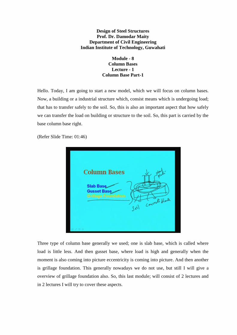
Three type of column base generally we used; one is slab base, which is called where
load is little less. And then gusset base, where load is high and generally when the
moment is also coming into picture eccentricity is coming into picture. And then another
is grillage foundation. This generally nowadays we do not use, but still I will give a
overview of grillage foundation also. So, this last module; will consist of 2 lectures and
in 2 lectures I will try to cover these aspects.

In fact, designing of slab base or gusset base or grillage foundation is almost similar type
and basically we have to distribute the concentrated load coming from column to base to
soil. So, when the load is coming from column; that load has to transfer to the soil, how
do we make it? First generally what we used to do. We used to first make say this is a
column, now this column is resting on a base plate, which is called base plate; some
plate, some thick plate we are going. To put to disperse the concentrated load, say load is
there to disperse into this area.
Then after that we are putting in a bigger area of concrete base right concrete block. So,
this is steel plate and this is concrete plate concrete block right. So, then it will be
transferred to the soil. So, in this way, in generally we use to transfer. Now, how to join
this column and this steel plate; this is 1 aspect. What should be the dimension of this
steel plate so that, the steel will be able to carry that plate will be able to carry that much
load; this aspect we have to see. Then what should be the dimension of the concrete
block, which would be able to carry that load, which is coming from the steel plate. And
then the dimension has to be decided on the basis of the soil bearing pressure.
So, the concrete block dimension will be means dimension in plan that length and width
of the concrete block has to be decided from the bearing pressure of soil. Similarly, the
steel plate dimension has to be decided from the bearing stress of the concrete, which we
are going to use. So, in this way step by step we have to see, in what way? The load can
be transferred safely to the soil. So, these aspects we will discuss right.

(Refer Slide Time: 04:47)
Now, first let us discuss on slab base, which is the simplest way to transfer the load from
superstructure to slab structure, from upper part to lower, means lower part means to soil
finally. Like a slab base consists of a thick steel base plate, placed over a concrete base
and connected to it through bolts. The base plate may either be welded to the stanchion
or else maybe to the column through cleat angle. So, through cleat angle we can make
stanchion, we will provide and it may be welded it may be bolted or riveted, whatever
means as per the requirement, as per the availability, as per the advantage of the site
condition etcetera, we have to see what sort of connections we will be going to do right.
(Refer Slide Time: 05:47)
So, first let us see; how does it look like. Say if we see in the side view or front view, it
will look like this. Say if this is a column right, now column is carrying load say P, now
on that we will put a plate, which is we generally term as base plate right. Then we will
put a concrete block right. Now, thickness of the concrete block, thickness of the base
plate; all these things will be decided from the calculation. That I will show. And this has
to be joined through some cleat angle right. So, this is column right and this is base plate
and this is concrete block right. So, this is the concrete, we are going to provide right.
Now, this will be connected through some anchor bolts. We may say this as anchor bolt
right. So, dimension of those things will be decided during design of the system right. In
this way, the means if we see the front view, it will look like this front view. Now, top
view if we see, this will look like this. So, this is the … if we see, this will be base plate
right. So, these are the concrete block, in top view I am trying to see right. I am drawing
this because; this will be required for calculation. So, let us draw in a final way.
Now, this is the column, say column is placed like this, say I column has been given.
Now, the size of the base plate will depend not only on the load, but also on other factors
like size of column and other things right. So, this is column. Now this is generally made
by anchor block. Similarly, in this side also it will be right. Now, this is the length of the
concrete block and this is the width of the concrete block. This is concrete block and this
is the base plate. In top view we are showing right.
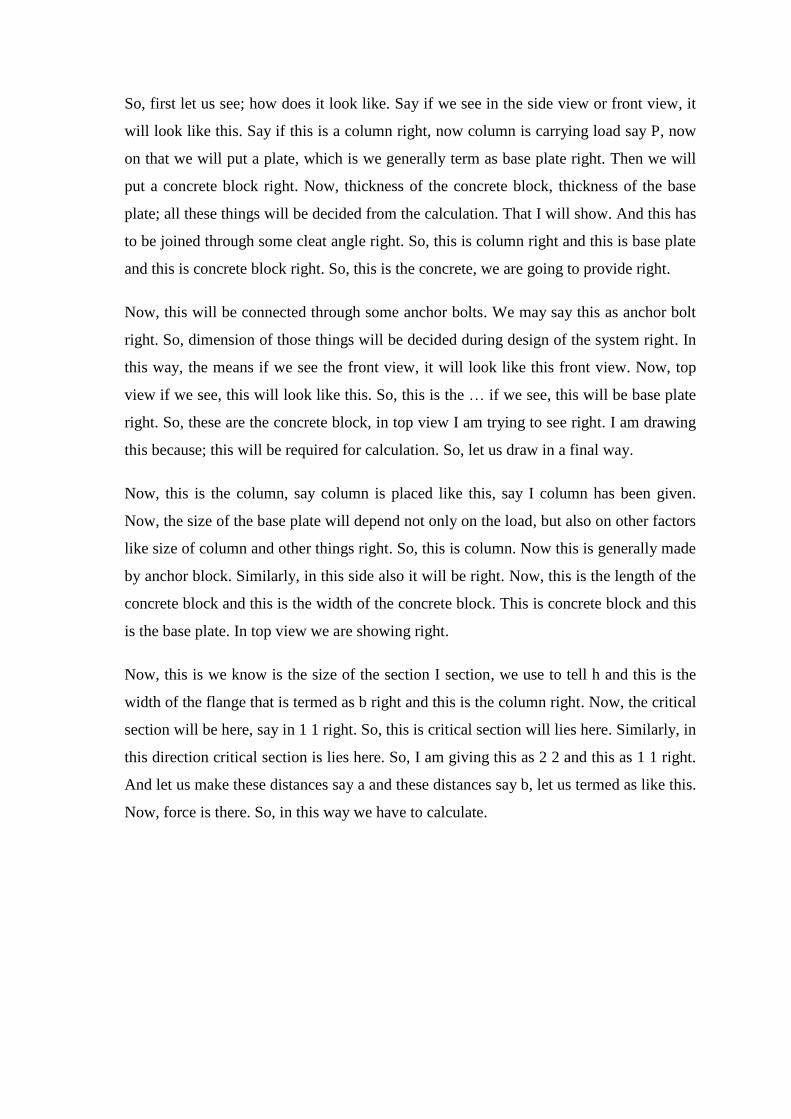
Now, this is we know is the size of the section I section, we use to tell h and this is the
width of the flange that is termed as b right and this is the column right. Now, the critical
section will be here, say in 1 1 right. So, this is critical section will lies here. Similarly, in
this direction critical section is lies here. So, I am giving this as 2 2 and this as 1 1 right.
And let us make these distances say a and these distances say b, let us termed as like this.
Now, force is there. So, in this way we have to calculate.

(Refer Slide Time: 11:17)
Before going to calculation, let me show the overall diagram that, say suppose force and
moment is coming from column right. Now, we have a base plate right. So, what will be
the pressure will develop here. If I see this will be a uniform pressure will develop right.
So, with magnitude this is P by A. If P is only there right and if area is this 1 means area
of this base plate right. Now, if moment also is acting, then we know that, due to moment
again such type of pressure will develop, that is like this right. So, this will be M by z
right.
So, now, if we add these 2 means resultant will become; either say like this means P by
A plus minus M by z that will be sigma b right or sigma, the stress developed at any
point will be like this. So, stress distribution will be in this way. Or if P by A is much
more than M by z, then this will become like this. If P by A is greater than this will be
developing like this right.
So, due to eccentricity of the load or due to development of moment, this will develop
right. Otherwise 1 another case may happen just when P by A is equal to M by z in this
case, here in left side it will be 0 and here if P by A is greater than M by z right. And
here P by A is less than M by z right. So, there are 3 cases will develop. So, in this way
stress will develop. So, when we will be going for design, what we have to see is that,
the maximum stress, maximum stress where it is going to develop.

So, maximum compressive stress is developing here, maximum tensile stress is
developing here. So, what will be the value right. And in for these 2 cases we can find
out the maximum stresses in this way and we can make it right. And we know that we
can find out the P by A if we means plus minus M by z is equal to sigma. If sigma is 0
that means, P by A is equal to M by z right. M by z means we can write Pe by z means 1
by 6 bt square right. So, if we divide P and A is equal to bt, then what will happen? So, P
by A is equal to P by A into say 6 e by t right. So, we can write e is equal to t by 6.
So, critical condition is e is equal to t by 6. So, that we have to see, whether it is coming
greater than t by 6 or less than t by 6. In this way we have to make it. Now, let us see the
diagram whatever we have made here, how to calculate the maximum stress coming and
how to design the base plate and the concrete based dimension.
(Refer Slide Time: 15:39)
That means, first let us assume some parameters like; say outer dimension of the column
as we told h and b means, if this is b and if this is h. So, this outer dimension of the
column will be h by b. And size of base plate, let us consider as L by D right. And the
greater projection of plate beyond column, let us denote as A this 1. And this position we
are denoting as b, the lesser projection of plate beyond column right. And t is the
thickness of the base plate. And w is the pressure of the base plate in Mpa. And sigma bs
is the permissible bending stress in the base plate. So, these are the some parameter,
which will be required for calculation of the dimension of the base plate right.
Remember this A and B is the projection of plate beyond the column right. 1 is greater
projection means in greater direction and another is lesser 1. And t is the thickness of the
base plate. Now, we have to find out L value, D value and t value of the base plate right.
(Refer Slide Time: 17:03)
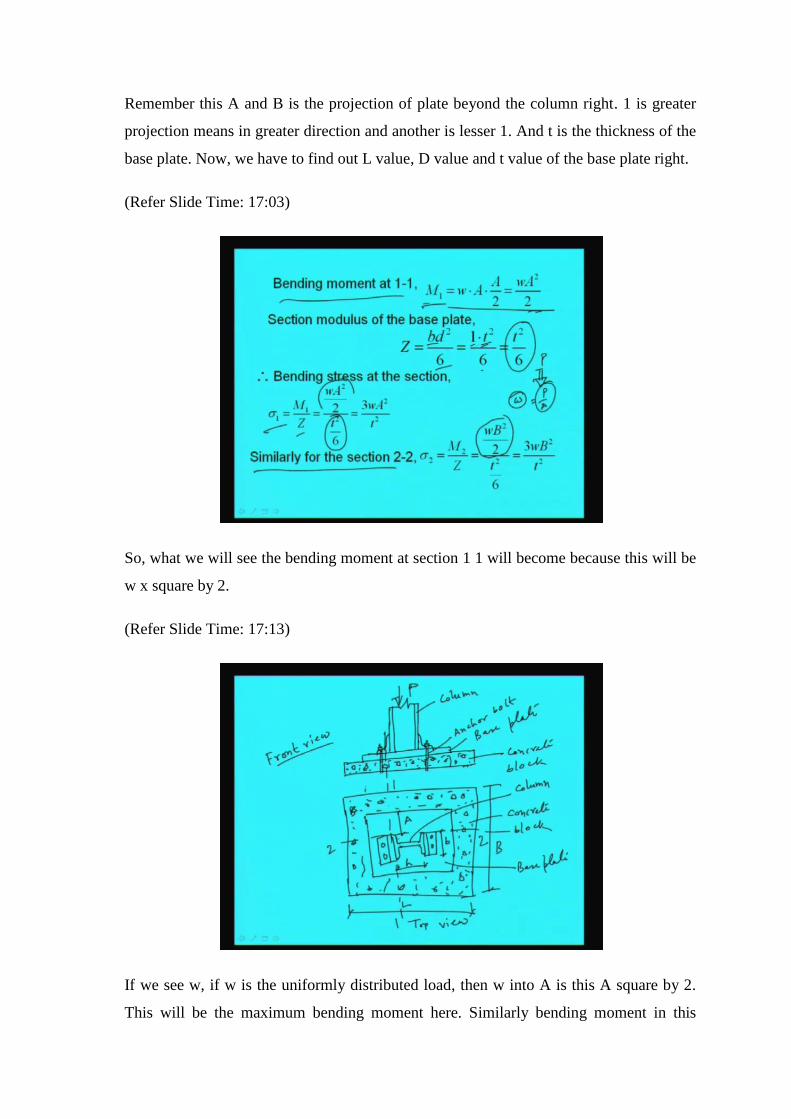
So, what we will see the bending moment at section 1 1 will become because this will be
w x square by 2.
(Refer Slide Time: 17:13)
If we see w, if w is the uniformly distributed load, then w into A is this A square by 2.
This will be the maximum bending moment here. Similarly bending moment in this
direction will be w b square by 2. So, w A square by 2. Now, the section modulus will
become bd square by 6, here b is nothing, but we are taking a unit value right. So, 1 into t
square, t is thickness of the base plate as we told by 6; that means; t square by 6. So,
section modulus we are going to find as t square by 6 and moment is developing as w A
square by 2.
So, bending stress will develop sigma 1 is equal to M 1 by z. M 1 is w A square by 2 and
by z is coming t square by 6. So, this will become 3 w A square by t square right. So,
bending stress at the section sigma 1 will become 3 w A square by t square. Remember
here only concentrated load is applied, there is no moment, assuming only concentrated
load and the column is applied right.
In fact, for base slab generally, we use means we use base slab only for concentrated
load. And when the eccentricity will be there or the moment will come into picture, in
that case generally we use the gusset base and when the load is very high. That we will
come later right. That is why the pressure on the plate is coming w, which is uniformly
distributed which is nothing, but P by A right. So, in that way we will calculate right.
So, similarly in section 2 2 this will become M 2 by z, M 2 will become similar way w b
square by 2 and z will become t square by 6. So, 3 w b square by t square. So, bending
stress at the section at the critical section is becoming 3 w A square by t square in 1 in
one’s direction. And in section 2 2 we are getting 3 w B square by t square.
(Refer Slide Time: 19:46)

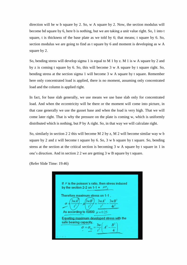
Now, if mu is the Poisson’s ratio, then stress induced by the section 2 2 on 1 1 can be
written as mu sigma 2 right. The stress induced by the section 2 2 on 1 1 will become mu
into sigma 2. So, what will happen? Sigma value will become that, sigma at section 1 1
minus sigma at section 2 2 means mu into sigma because, this is the stress induced on 1 1
due to the section 2 2. So, if we put those values, we will get the value like this that, 3 w
A square by t square minus mu into 3 w B square by t square.
Now, as per IS code, we will see the Poisson’s ratio is generally taken as 0.25. So, if we
put the value of 0.25 in this equation, we will get this value; that is, 3 w A square by t
square minus 3 w B square by 4 t square right. Now, if we equate this with the bearing
capacity of the plate, then we will get sigma is equal to sigma bs is equal to this right.
This is the value of this 1; 3 w by t square into A square minus B square by 4 right. Now,
we can find out from this equation of value of t thickness right.
(Refer Slide Time: 21:21)
So, thickness will become square root of 3 w by sigma bs into A square minus B square
by 4 right. So, thickness of the base plate can be find out from this. Now, for solid round
steel columns, the thickness can be expressed in this way; 10 into square root of 90 W by
16 sigma bs into B minus B B by B minus d 0 right, where this W is total axial load in
kilo Newton total axial load in kilo Newton. And B is the length of side of cap or base in
millimeter and it has to be greater than 1.5 into d 0 plus 75. What is d 0? d 0 is the
diameter of the reduced end, if any of the column in millimeter. And sigma bs is the safe

bearing capacity of the steel, that is, 185 Mpa. As per codal provision, this value of
sigma bs is 185 Mpa.
(Refer Slide Time: 22:47)
Now, the allowable intensity of pressure on concrete may be assumed as 4 Newton per
millimeter square because, in general we assume 4 Newton per millimeters as allowable
stress in concrete, allowable intensity of pressure in concrete we assume this. Now, when
the base slab does not distribute the load uniformly or where the slab is not rectangular,
separate calculation shall be made, so that stresses are within the specified limit. So,
whatever we have shown here, the that thing will not happen, if the slab does not
distribute the load uniformly or where slab is not rectangular, then we have to calculate
accordingly and if moment is there also right. So, case to case it may vary. The simplest
case just we are showing here right.

(Refer Slide Time: 23:43)
Now, this will be clear if we go through 1 small example. Whatever discussions we have
done here, through that we will go through 1 example then you will be cleared right.
What is the example? That is design a suitable base plate to carry an axial load of 2900
kilo Newton. So, axial load P is equal to 2900 kilo Newton. The base plate rests on
concrete of M 15 grade concrete, the plate is resting on M 15 grade of concrete. The
column section is ISHB 350 at 67.4 kg per meter. So, the column section size is given
that is ISHB 350 right.
The safe bearing pressure on the column may be assumed as 4100 kilo Newton per meter
square right. The safe bearing pressure on the column may be assumed as 4100 kilo
Newton per meter square. What will be the depth of concrete base if safe bearing
capacity of soil is 250 kilo Newton per meter square, if safe bearing capacity of soil is
considered as 250 kilo Newton per meter square? So, we have to find out the depth of
concrete base means; the dimension of base plate and the concrete base right. So, with
this data let us try to solve this.
(Refer Slide Time: 25:18)
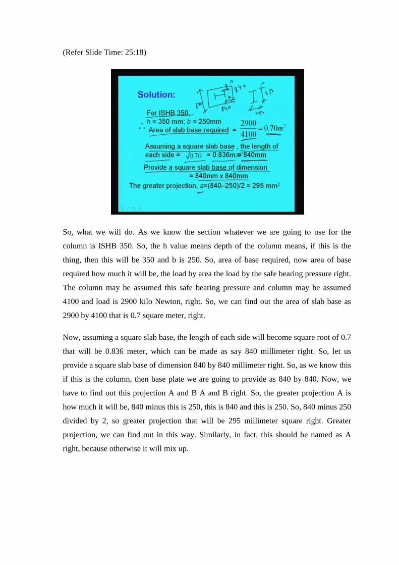
So, what we will do. As we know the section whatever we are going to use for the
column is ISHB 350. So, the h value means depth of the column means, if this is the
thing, then this will be 350 and b is 250. So, area of base required, now area of base
required how much it will be, the load by area the load by the safe bearing pressure right.
The column may be assumed this safe bearing pressure and column may be assumed
4100 and load is 2900 kilo Newton, right. So, we can find out the area of slab base as
2900 by 4100 that is 0.7 square meter, right.
Now, assuming a square slab base, the length of each side will become square root of 0.7
that will be 0.836 meter, which can be made as say 840 millimeter right. So, let us
provide a square slab base of dimension 840 by 840 millimeter right. So, as we know this
if this is the column, then base plate we are going to provide as 840 by 840. Now, we
have to find out this projection A and B A and B right. So, the greater projection A is
how much it will be, 840 minus this is 250, this is 840 and this is 250. So, 840 minus 250
divided by 2, so greater projection that will be 295 millimeter square right. Greater
projection, we can find out in this way. Similarly, in fact, this should be named as A
right, because otherwise it will mix up.

(Refer Slide Time: 27:40)
And the smaller projection say B right, B will become 840 minus 350 by 2 because, in
this direction what will happen, if base plate is 840 and if this is 350 then this will
become 840 minus 350 by 2 and calculating this, we will be getting 245. So, we are
getting A is equal to 295 and B is equal to 245 millimeter right. Now, the pressure below
the base slab, we can find out, what will be the pressure below the base slab. The load by
the area of base slab, load is 2900 kilo Newton. So, we are making Newton by 840 into
840. So, this becoming pressure becoming 4.12 Newton per millimeter square. So,
pressure below the slab base is becoming 4.12 Newton per millimeter square right.
(Refer Slide Time: 28:52)

Then what we will do, other thing is the thickness. So, thickness we can find now
because, now we know the pressure w is 4.12. So, on that basis, we can find out the
thickness from the formula. If this is A and if this is B, we can write t is equal to square
root of 3 w by sigma bs into A square minus B square by 4 is equal to square root of 3
into w is 4.12 and sigma bs is 185 A is 295 and B is 245. If we put those values, we will
get thickness t as 62 millimeter. So, the base slab which we need to provide is 840 by
840 by 62 millimeter right. So, we can provide a base slab of 840 by 840 by 62
millimeter. So, in this way we can find out the dimension of the base slab. Now, what we
will do.
(Refer Slide Time: 30:00)
Now, we will find out the dimension of the concrete base right. So, in case of concrete
base what we will do, we can assume say 15 percent as self-weight of the foundation. So,
total load will little increase, that is, 1.15 W, 1.15 W means 2900 kilo Newton, so 1.15
into 2900 that will become 333335 kilo Newton right. So, area of concrete base will
become 3335 by 250 because, 250 is the allowable pressure. So, 3335 by 250 that is
13.34 meter square. So, area of concrete base is becoming 13.34 meter square.
So, length of each side of the concrete base will be required square root of 13.34 if it is a
square block. So, that is becoming 3.65 meter, right. Now, assuming angle of dispersion
of load at say 45 degree then what will be the depth of concrete slab. Because, you see if
the load is dispersing at an angle of 45 degree then we have to find out the depth. So, that
dispersion happens properly right. So, depth of concrete slab will become say 3.65 minus
0.84 this is the length of the concrete base and this is the length of the base plate. So, this
by 2 that is depth of concrete slab will become 1.4.
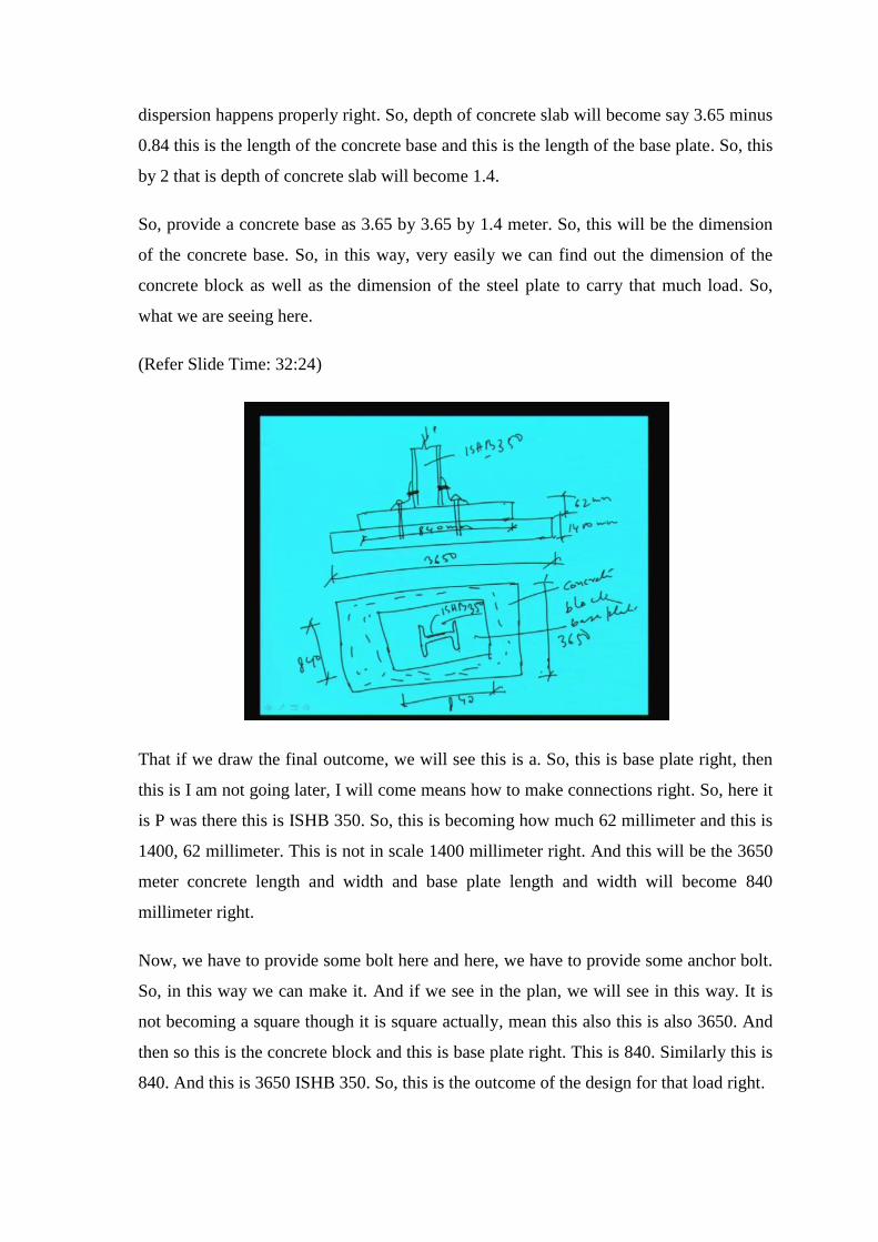
So, provide a concrete base as 3.65 by 3.65 by 1.4 meter. So, this will be the dimension
of the concrete base. So, in this way, very easily we can find out the dimension of the
concrete block as well as the dimension of the steel plate to carry that much load. So,
what we are seeing here.
(Refer Slide Time: 32:24)
That if we draw the final outcome, we will see this is a. So, this is base plate right, then
this is I am not going later, I will come means how to make connections right. So, here it
is P was there this is ISHB 350. So, this is becoming how much 62 millimeter and this is
1400, 62 millimeter. This is not in scale 1400 millimeter right. And this will be the 3650
meter concrete length and width and base plate length and width will become 840
millimeter right.
Now, we have to provide some bolt here and here, we have to provide some anchor bolt.
So, in this way we can make it. And if we see in the plan, we will see in this way. It is
not becoming a square though it is square actually, mean this also this is also 3650. And
then so this is the concrete block and this is base plate right. This is 840. Similarly this is
840. And this is 3650 ISHB 350. So, this is the outcome of the design for that load right.
(Refer Slide Time: 35:34)
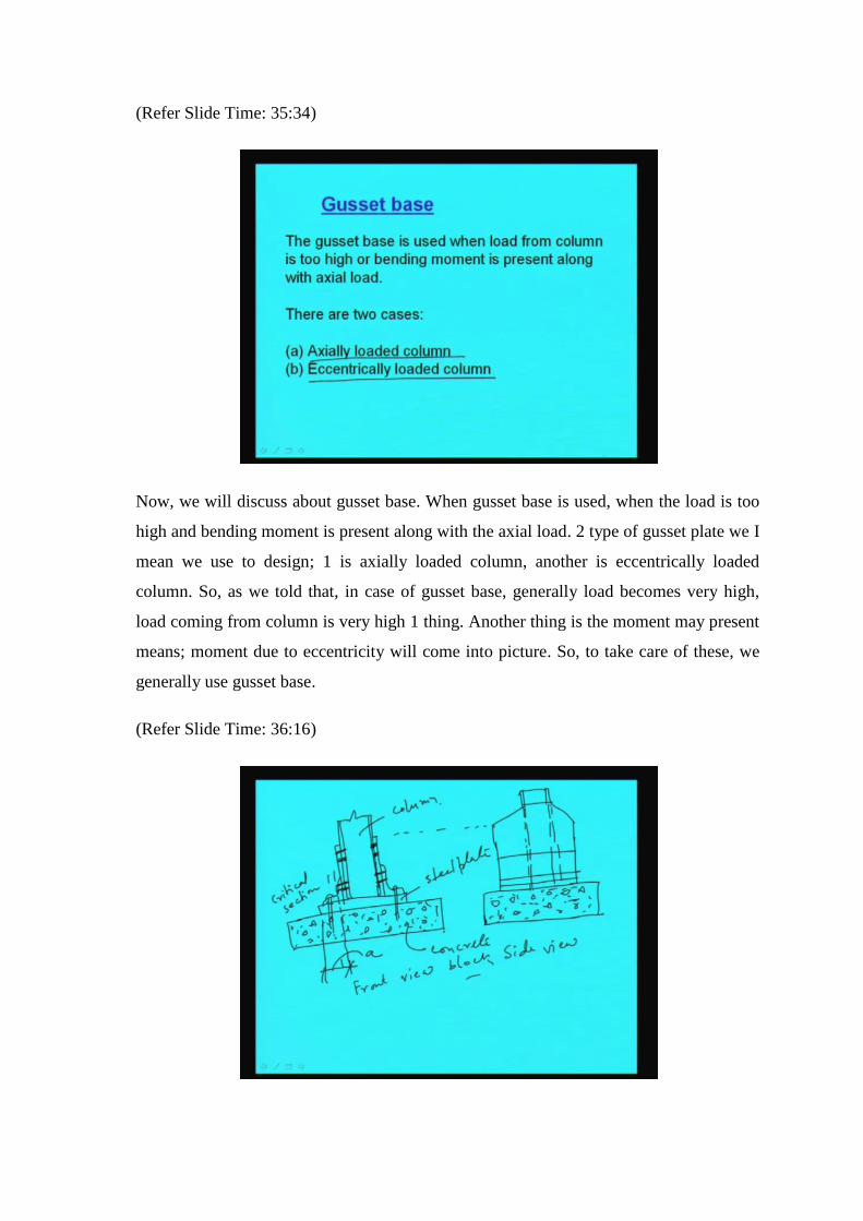
Now, we will discuss about gusset base. When gusset base is used, when the load is too
high and bending moment is present along with the axial load. 2 type of gusset plate we I
mean we use to design; 1 is axially loaded column, another is eccentrically loaded
column. So, as we told that, in case of gusset base, generally load becomes very high,
load coming from column is very high 1 thing. Another thing is the moment may present
means; moment due to eccentricity will come into picture. So, to take care of these, we
generally use gusset base.
(Refer Slide Time: 36:16)
Let us see how it looks like. Say this is a column right and this will be the base plate,
then concrete block right. Here we use to provide additional gusset plate here, to take
care of the moment right. Now, this is front view and this the concrete block right. And
critical sections will lie, where this will be in this. So, section 1 1 this will be the critical
section through, which we have to design right.
Now, here we can provide some bolt or rivet right. And here also we have to provide
some anchor block right, this is if we see front view. And in side view, we will see like
this side view will be right. It will be and this is the column. So, this will be right, this is
the column right. So, this is the concrete block this is side view and this is column. Just I
will take some from here. So, this is column, this is steel plate and this concrete block
right.
(Refer Slide Time: 40:59)
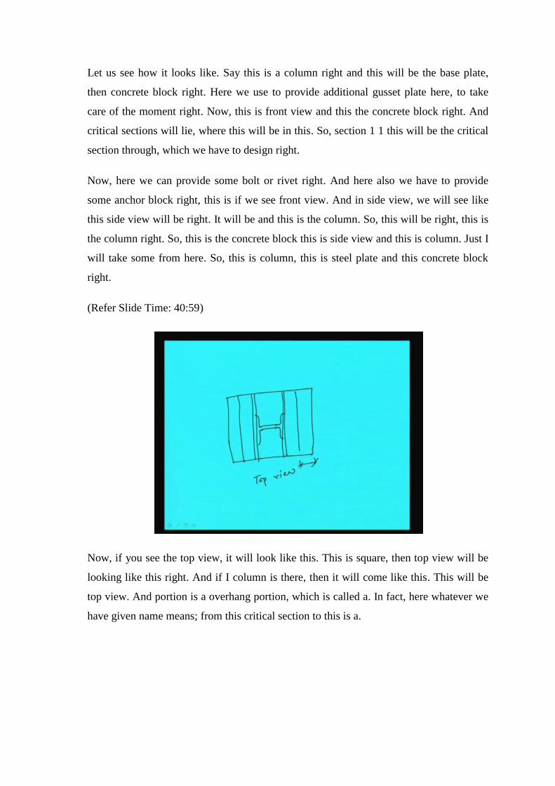
Now, if you see the top view, it will look like this. This is square, then top view will be
looking like this right. And if I column is there, then it will come like this. This will be
top view. And portion is a overhang portion, which is called a. In fact, here whatever we
have given name means; from this critical section to this is a.

(Refer Slide Time: 41:52)
Now, in a gusseted base, if part of the load is transmitted from the stanchions through the
gussets to the base slab, as we told. The gussets and stiffeners bear the base slab against
bending and therefore, a thinner base plate can be provided. So, the utility is means
advantage is that, the gusset and stiffeners can bear the base slab against bending. And
that is why the thinner base plate means; thinner section of the base plate may be
sufficient to carry that much bending and the load. That is why we use such type of
configuration.
(Refer Slide Time: 42:36)
Now, in clause 5.4.1, it told that, for stanchion with gusseted bases, the gusset plate’s
cleat angles fastenings etcetera, in combination with the bearing area of the shaft, shall
be sufficient to take the loads bending moments and reactions to the base plate, without
exceeding specified stress. All the bearing surfaces shall be matching to ensure perfect
contact right. So, once again I am just telling which is written exactly in the code same
language, that is, for stanchion with gusseted bases, the gusset plates, cleat angles
fastenings etcetera, in combination with the bearing area of the slab, shall be sufficient to
take the loads bending moments and reactions to the base plate without exceeding
specified stresses right.
Now, if a is the length between the root of the angle and the edge of the base plate, then
the cantilever moment Mp means; that for that hanging portion, will become w a square
by 2 right. The cantilever means this moment will become w a square by 2, if w is the
load means uniformly distributed load is coming.
(Refer Slide Time: 44:05)
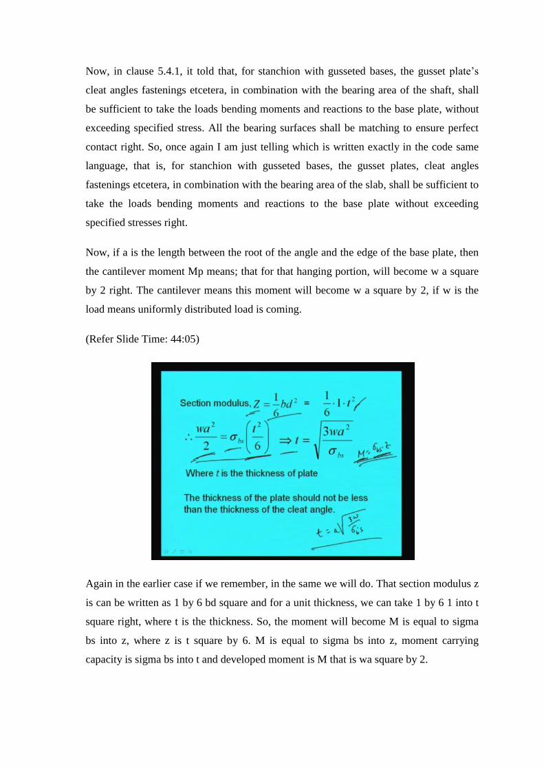
Again in the earlier case if we remember, in the same we will do. That section modulus z
is can be written as 1 by 6 bd square and for a unit thickness, we can take 1 by 6 1 into t
square right, where t is the thickness. So, the moment will become M is equal to sigma
bs into z, where z is t square by 6. M is equal to sigma bs into z, moment carrying
capacity is sigma bs into t and developed moment is M that is wa square by 2.
So, equating these 2 equation, we will get t the thickness of the plate will be square root
of 3 wa square by 6 sigma bs square root of 3 wa square by sigma bs. Or we can write
say t is equal to a into 3 w by sigma bs right t is equal to a into square root of 3 w by
sigma bs, where w is the pressure coming in the plate and a is the cantilever portion that
is hanging and sigma bs is the allowable bearing stress in plate right. That is generally
185.
Now, the thickness of the plate should not be less than the thickness of the cleat angle
that we have to see; whatever cleat angle we are going to use, we are going use the cleat
angle here. So, this thickness of the plate should not be less than the thickness of the
cleat angle right. So, that also we have to keep in mind when we will go for designing.
(Refer Slide Time: 45:54)
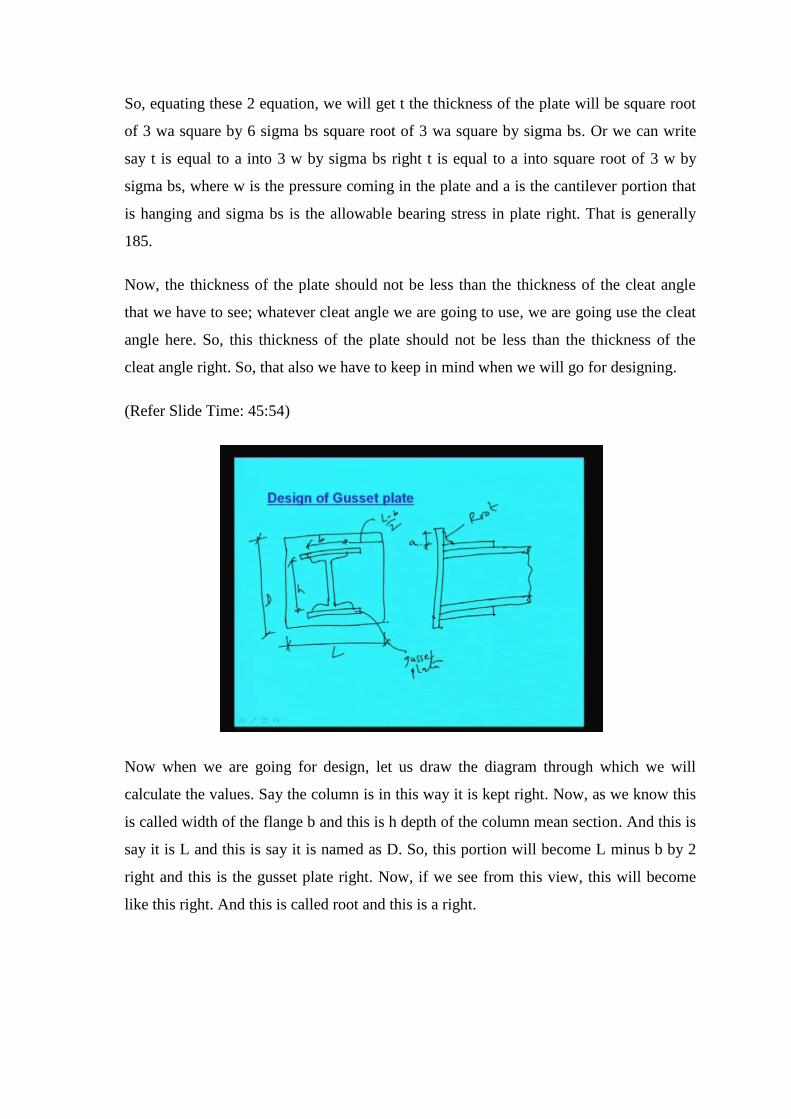
Now when we are going for design, let us draw the diagram through which we will
calculate the values. Say the column is in this way it is kept right. Now, as we know this
is called width of the flange b and this is h depth of the column mean section. And this is
say it is L and this is say it is named as D. So, this portion will become L minus b by 2
right and this is the gusset plate right. Now, if we see from this view, this will become
like this right. And this is called root and this is a right.

(Refer Slide Time: 48:08)
Now, if we calculate the cantilever load on the gusset plate, then we can find out that, the
cantilever load on gusset plate Fgc if we termed it, then half into wD by 2 into L minus b
half into wD by 2 into L minus b right. So, this will become the cantilever load will
become wD by 4 into L minus b. And moment in the gusset plate as a cantilever for the
length of L minus b by 2 will become load into distance by 2 right. So, wD by 4 means
this will become wD by 4 into L minus b into this is L minus b by 4. So, that will
become wD by 16 into L minus b whole square. So, moment in gusset plate will become
wD by 16 into L minus b whole square. So, in this way we find out the moment right.
(Refer Slide Time: 49:22)
Now, the some codal provisions we have to keep in mind, while going for the designing.
That the thickness of the gusset plate should not be less than 10 mm, the thickness of the
gusset plate has to be at least 10 mm, that is, the codal provision is given. So, we have to
keep in mind while going for designing. The base plate should be designed on the basis
of bending moment, on the projection beyond the gusset plate, in case the gusset plate is
welded to the base plate, in case the gusset plate is welded to the base plate. So, this also
we have to keep in mind.
(Refer Slide Time: 50:02)
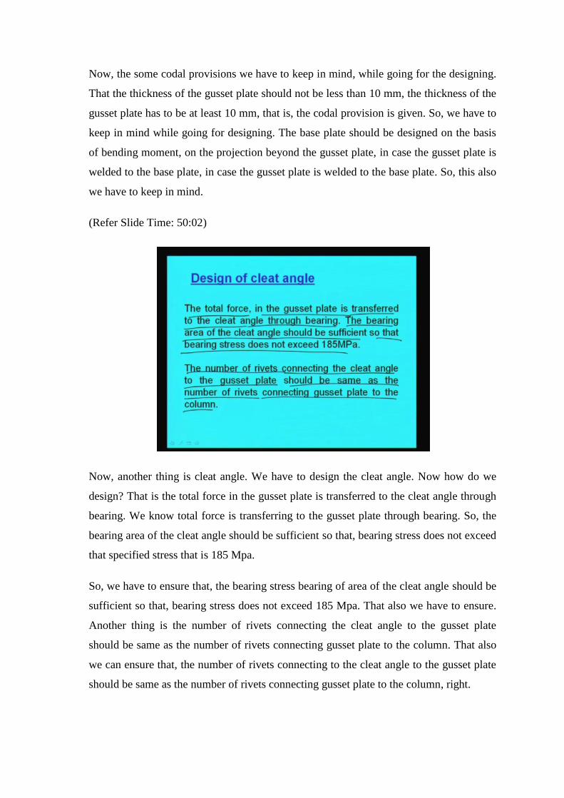
Now, another thing is cleat angle. We have to design the cleat angle. Now how do we
design? That is the total force in the gusset plate is transferred to the cleat angle through
bearing. We know total force is transferring to the gusset plate through bearing. So, the
bearing area of the cleat angle should be sufficient so that, bearing stress does not exceed
that specified stress that is 185 Mpa.
So, we have to ensure that, the bearing stress bearing of area of the cleat angle should be
sufficient so that, bearing stress does not exceed 185 Mpa. That also we have to ensure.
Another thing is the number of rivets connecting the cleat angle to the gusset plate
should be same as the number of rivets connecting gusset plate to the column. That also
we can ensure that, the number of rivets connecting to the cleat angle to the gusset plate
should be same as the number of rivets connecting gusset plate to the column, right.
(Refer Slide Time: 51:13)
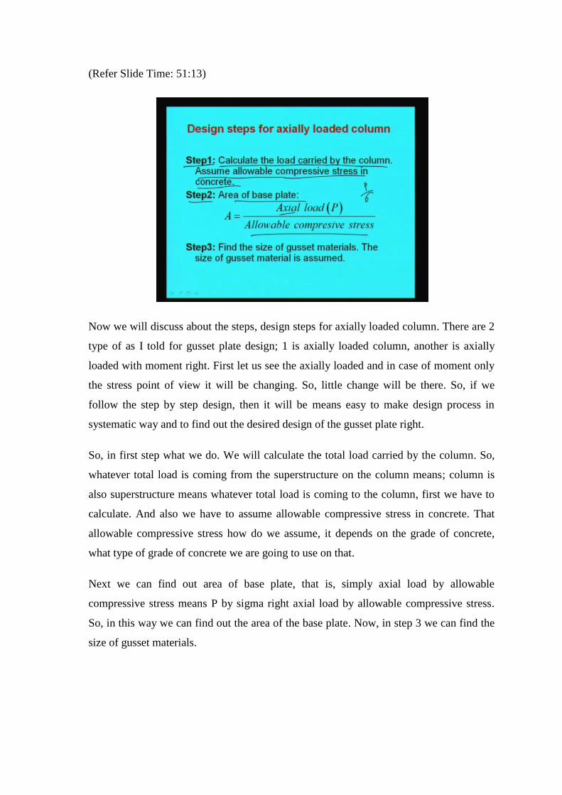
Now we will discuss about the steps, design steps for axially loaded column. There are 2
type of as I told for gusset plate design; 1 is axially loaded column, another is axially
loaded with moment right. First let us see the axially loaded and in case of moment only
the stress point of view it will be changing. So, little change will be there. So, if we
follow the step by step design, then it will be means easy to make design process in
systematic way and to find out the desired design of the gusset plate right.
So, in first step what we do. We will calculate the total load carried by the column. So,
whatever total load is coming from the superstructure on the column means; column is
also superstructure means whatever total load is coming to the column, first we have to
calculate. And also we have to assume allowable compressive stress in concrete. That
allowable compressive stress how do we assume, it depends on the grade of concrete,
what type of grade of concrete we are going to use on that.
Next we can find out area of base plate, that is, simply axial load by allowable
compressive stress means P by sigma right axial load by allowable compressive stress.
So, in this way we can find out the area of the base plate. Now, in step 3 we can find the
size of gusset materials.

(Refer Slide Time: 52:56)
The size of gusset material can be assumed. And in this way, we can find out the size of
gusset materials. First is the assumed thickness of gusset plate should be should not be
less than 16 mm assumed thickness of gusset plate should not be less than 16 mm. This
is first. Second is the gusset angle is chosen so as to accommodate 2 rows of rivets in the
vertical leg and 1 row of rivets in the horizontal leg right. So, 1 row of rivet will be in
horizontal leg and 2 rows of rivet in the vertical leg. And generally, we use an unequal
angle unequal angle we generally use. The length of gusset material is normally kept
equal to the length of base plate parallel to the flange of the column right, parallel to the
flange of the column.
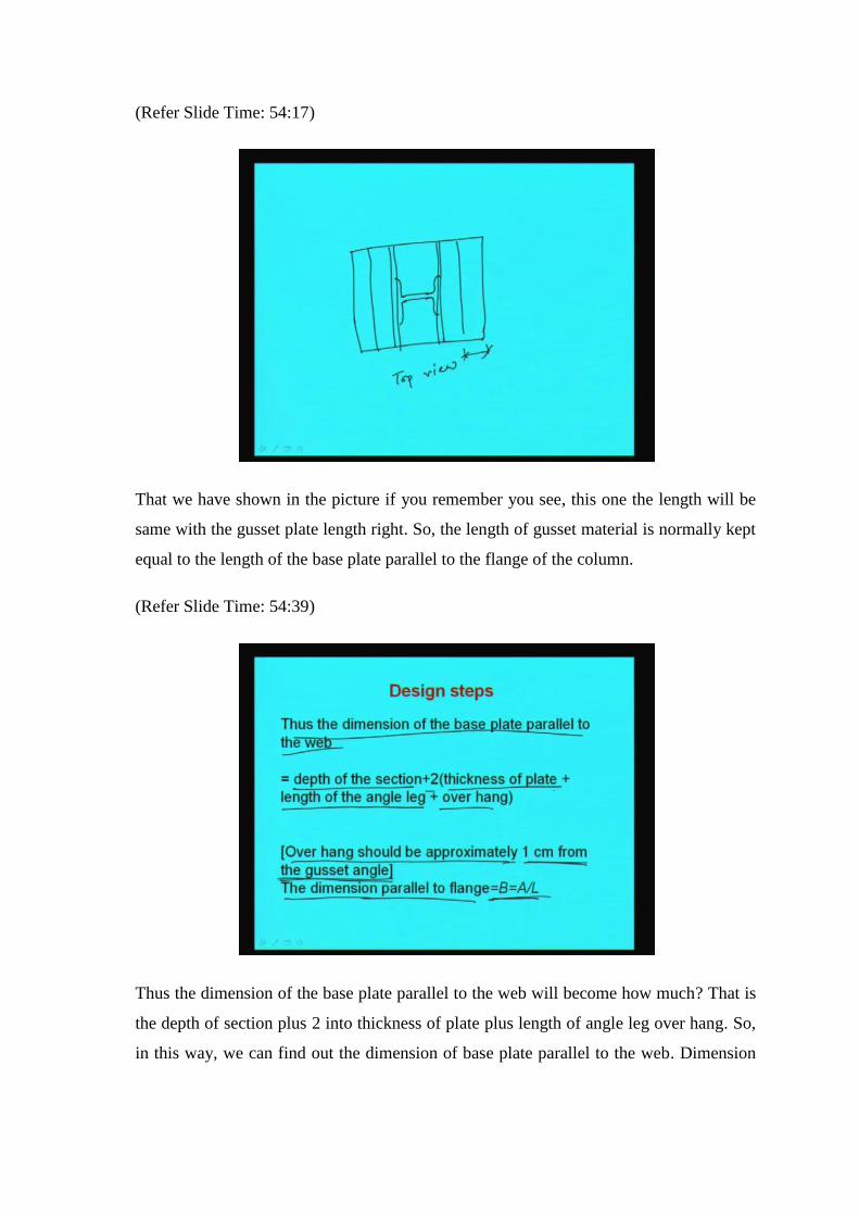
(Refer Slide Time: 54:17)
That we have shown in the picture if you remember you see, this one the length will be
same with the gusset plate length right. So, the length of gusset material is normally kept
equal to the length of the base plate parallel to the flange of the column.
(Refer Slide Time: 54:39)
Thus the dimension of the base plate parallel to the web will become how much? That is
the depth of section plus 2 into thickness of plate plus length of angle leg over hang. So,
in this way, we can find out the dimension of base plate parallel to the web. Dimension
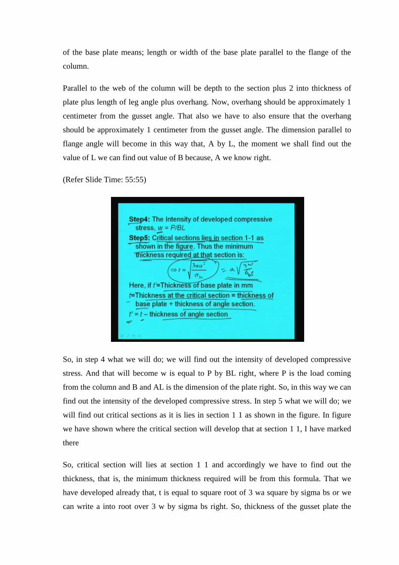
of the base plate means; length or width of the base plate parallel to the flange of the
column.
Parallel to the web of the column will be depth to the section plus 2 into thickness of
plate plus length of leg angle plus overhang. Now, overhang should be approximately 1
centimeter from the gusset angle. That also we have to also ensure that the overhang
should be approximately 1 centimeter from the gusset angle. The dimension parallel to
flange angle will become in this way that, A by L, the moment we shall find out the
value of L we can find out value of B because, A we know right.
(Refer Slide Time: 55:55)
So, in step 4 what we will do; we will find out the intensity of developed compressive
stress. And that will become w is equal to P by BL right, where P is the load coming
from the column and B and AL is the dimension of the plate right. So, in this way we can
find out the intensity of the developed compressive stress. In step 5 what we will do; we
will find out critical sections as it is lies in section 1 1 as shown in the figure. In figure
we have shown where the critical section will develop that at section 1 1, I have marked
there
So, critical section will lies at section 1 1 and accordingly we have to find out the
thickness, that is, the minimum thickness required will be from this formula. That we
have developed already that, t is equal to square root of 3 wa square by sigma bs or we
can write a into root over 3 w by sigma bs right. So, thickness of the gusset plate the
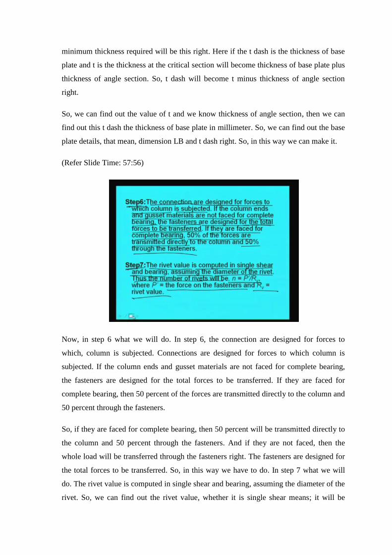
minimum thickness required will be this right. Here if the t dash is the thickness of base
plate and t is the thickness at the critical section will become thickness of base plate plus
thickness of angle section. So, t dash will become t minus thickness of angle section
right.
So, we can find out the value of t and we know thickness of angle section, then we can
find out this t dash the thickness of base plate in millimeter. So, we can find out the base
plate details, that mean, dimension LB and t dash right. So, in this way we can make it.
(Refer Slide Time: 57:56)
Now, in step 6 what we will do. In step 6, the connection are designed for forces to
which, column is subjected. Connections are designed for forces to which column is
subjected. If the column ends and gusset materials are not faced for complete bearing,
the fasteners are designed for the total forces to be transferred. If they are faced for
complete bearing, then 50 percent of the forces are transmitted directly to the column and
50 percent through the fasteners.
So, if they are faced for complete bearing, then 50 percent will be transmitted directly to
the column and 50 percent through the fasteners. And if they are not faced, then the
whole load will be transferred through the fasteners right. The fasteners are designed for
the total forces to be transferred. So, in this way we have to do. In step 7 what we will
do. The rivet value is computed in single shear and bearing, assuming the diameter of the
rivet. So, we can find out the rivet value, whether it is single shear means; it will be
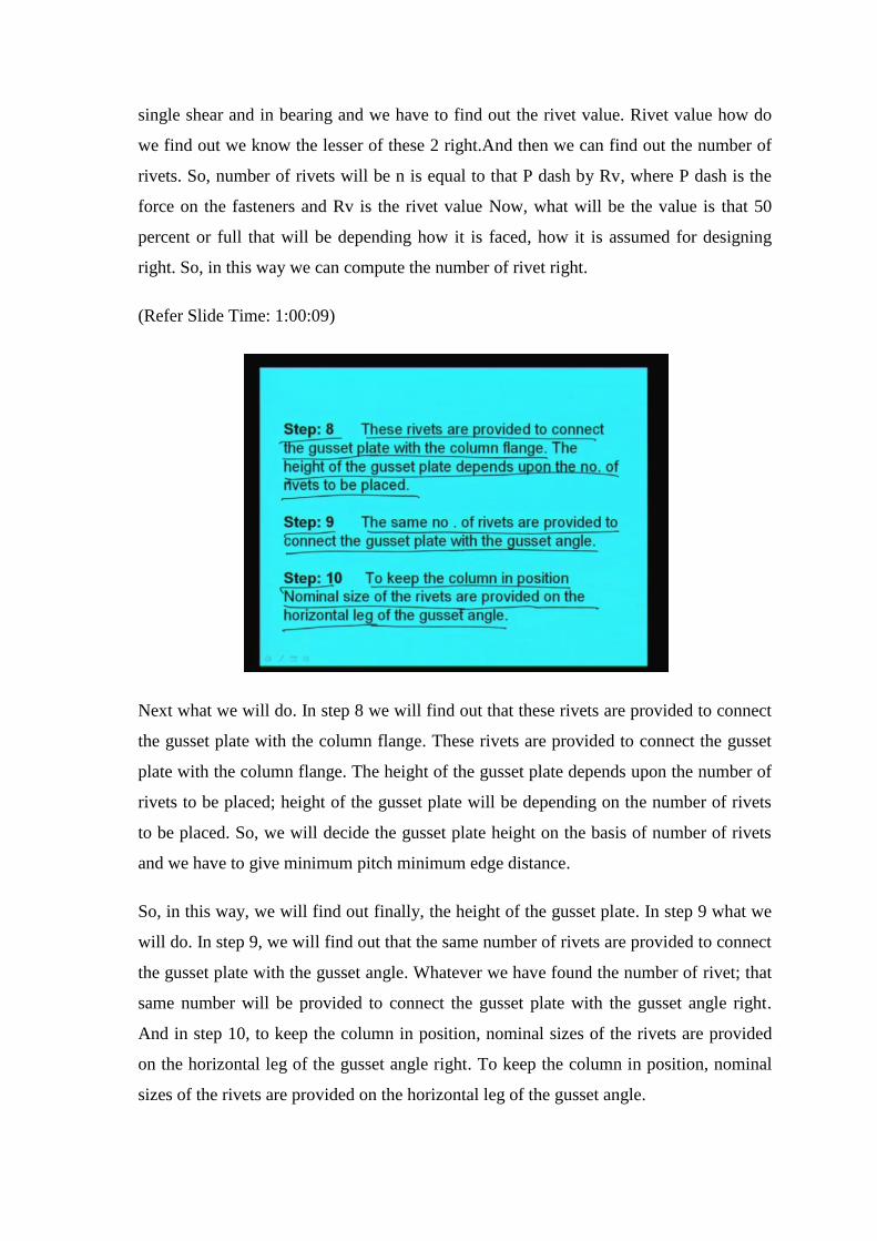
single shear and in bearing and we have to find out the rivet value. Rivet value how do
we find out we know the lesser of these 2 right.And then we can find out the number of
rivets. So, number of rivets will be n is equal to that P dash by Rv, where P dash is the
force on the fasteners and Rv is the rivet value Now, what will be the value is that 50
percent or full that will be depending how it is faced, how it is assumed for designing
right. So, in this way we can compute the number of rivet right.
(Refer Slide Time: 1:00:09)
Next what we will do. In step 8 we will find out that these rivets are provided to connect
the gusset plate with the column flange. These rivets are provided to connect the gusset
plate with the column flange. The height of the gusset plate depends upon the number of
rivets to be placed; height of the gusset plate will be depending on the number of rivets
to be placed. So, we will decide the gusset plate height on the basis of number of rivets
and we have to give minimum pitch minimum edge distance.
So, in this way, we will find out finally, the height of the gusset plate. In step 9 what we
will do. In step 9, we will find out that the same number of rivets are provided to connect
the gusset plate with the gusset angle. Whatever we have found the number of rivet; that
same number will be provided to connect the gusset plate with the gusset angle right.
And in step 10, to keep the column in position, nominal sizes of the rivets are provided
on the horizontal leg of the gusset angle right. To keep the column in position, nominal
sizes of the rivets are provided on the horizontal leg of the gusset angle.

So, these are the steps which we have to follow, for designing a gusset base. So, the
design steps of both the cases we have told. So, only we could not solve the example of
gusset base, which we will do in next class and I think then it will be clear. So, with this I
will have to conclude today’s lecture.
Thank you very much.