designing low power wireless systems telos / tmote sky joe polastre uc berkeley moteiv corporation
TRANSCRIPT

Designing Low Power Wireless Systems
Telos / Tmote Sky
Joe PolastreUC Berkeley
Moteiv Corporation

2
Faster, Smaller, Numerous
year
log
(p
eo
ple
pe
r c
om
pu
ter)
Streaming Data to/from the
Physical World
Moore’s Law “Stuff” (transistors, etc)
doubling every 1-2 years
Bell’s Law New computing class
every 10 years

3
ApplicationsDensity & Scale
Sample Rate & Precision
MobilityLow Latency
Disconnection & Lifetime
Monitoring Habitat Monitoring Integrated Biology Structural Monitoring
Interactive and Control Pursuer-Evader Intrusion Detection Automation

4
Berkeley Motes Timeline
WeC“Smart Rock”
1999 2000
Rene’“Experimentation”
2001 2002 2003 2004
Dot“Scale”
Mica“Open Experimental Platform”
Spec “Mote on a chip”
Telos“Integrated Platform”

5
Low Power Operation
Efficient Hardware Integration and Isolation
Complementary functionality (DMA, USART, etc) Selectable Power States (Off, Sleep, Standby) Operate at low voltages and low current
Run to cut-off voltage of power source
Efficient Software Fine grained control of hardware Utilize wireless broadcast medium Aggregate

6
Typical WSN Application
sleepw
akeu
p
Short active time• processing• data acquisition• communication
Po
wer
Time
Communications Periodic
Data Collection Network Maintenance
Triggered Events Detection/Notification
Duty Cycled Sleep 99+% of time
Active time is very short Milliseconds or less
Long Lifetime Months to Years without
changing batteries Power management is the key
to WSN success

7
Design Principles
Key to Low Duty Cycle Operation:
Sleep – majority of the time Wakeup – quickly start processing Active – minimize work & return to sleep
For long lived wireless networks, optimize sleep, then wakeup, then active current consumption and processing time For low duty cycle networks, active mode optimizations (like
dynamic voltage scaling) provide insignificant benefits

8
Sleep
Majority of time, node is asleep >99%
Minimize sleep current through Isolating and shutting down individual circuits Using low power hardware
Need RAM retention Run auxiliary hardware components from low
speed oscillators (typically 32kHz) Perform ADC conversions, DMA transfers, and bus
operations while microcontroller core is stopped

9
Overhead of switching from Sleep to Active Mode Reduce wasted energy due to switching modes
Wakeup
Microcontroller Radio (IEEE 802.15.4)
1– 10 ms typical
1.6 ms
-0.5 0 0.5 1 1.5 2 2.50
10
20
30
Time (ms)
Cu
rren
t (m
A)
osc onload regs
cap chargingenter
rx rx
10ns – 4ms typical292 ns
Texas Instruments MSP430 Fx1xx Chipcon CC2420
Time (ns)

10
Active
Microcontroller Fast processing, low active
power Avoid external oscillators
Radio High data rate, low power
tradeoffs Increased complexity vs
robusness to noise
External Flash (stable storage) Data logging, network code
reprogramming, aggregation High power consumption Long writes
Radio vs. Flash 250kbps radio sending 1 byte
Energy : 1.5J Duration : 32s
Atmel flash writing 1 byte Energy : 3J Duration : 78s

11
Selecting a Radio
Narrowband Low bit rate (< 250kbps) Lower frequencies
higher range Simple channel modulation Susceptible to noise
(narrow frequency use) Low power consumption
(<15mA) Fast wakeup times
(some may be clocked by MCU)
Examples:RFM TR1000, Chipcon CC1020
Wideband High bit rate (100kbps+) High frequencies Global ISM
band at 2.4GHz Complex channel modulation Robust to noise
(using spreading codes) High power consumption
(>20mA) Slow wakeup times
(must start external oscillators)
Examples:IEEE 802.15.4, Bluetooth

12
Microcontroller Memory Trends
Available RAM has stayed fairly constant
Instead of increasing RAM, extra die space used for hardware modules DMA: increases
performance AND lowers power consumption
1975 1980 1985 1990 1995 2000 20050
20
40
60
80
100
120
140
Year
Kilo
byt
es
FlashRAM

13
Accelerators vs Modules
Hardware Modules Software routines pushed
into hardware Lose flexibility
Example: encryption Isolated to specific
component Radio or Microcontroller
Examples: Packet handling support Encryption Data busses and Timers
Accelerators Break modules up into
accelerators Let software tie them
together Considerable flexibility Spec (Jason Hill thesis)
Examples: RF Interrupt Handling Encryption Simple DMA for Tx/Rx
Unfortunately, most manufacturers are moving to Modules, not AcceleratorsExamples: Newly released Chipcon CC2430, Ember EM250

14
Putting it all togetherLow Power Microcontroller
WirelessTransceiver
Real Time Clock32.768kHz
for low power modes
Low ESR fast starting oscillator
Disconnect unused peripherals

15
Telos
Applications Monitoring – H/VAC,
Structural, Environmental, Medical
Principles Low Power
Long Lifetime Easy to use Robust hardware and
software High Performance

16
Wireless sensor module for building applications
Standards Based USB IEEE 802.15.4/Zigbee TinyOS Expansion to other sensors
Low Power Hardware designed from
software principles for low power operation
Isolation, buffering, fast wakeup from sleep
Low Cost Integrated design 50m range indoors 125m range outdoors
IEEE 802.15.4 New wireless standard
for low power communication CC2420 radio 250kbps 2.4GHz ISM band Zigbee-compatible
Telos

17
Low Power Operation
TI MSP430 -- Advantages over other microcontrollers 16-bit core 12-bit ADC < 50nA port leakage
(vs. 1A for Atmels) Double buffered data
buses Interrupt priorities Calibrated DCO
Integrated wireless module Buffers and Transistors Switch on/off each
sensor and componentsubsystem

18
Hardware Isolation
Experiences from Great Duck Island One component failure kills entire system Must isolate and detect failures Remove/Turn off voltage regulators
Each “sub-circuit” on Telos is isolated Microcontroller turns on/off Fine-grained control of power consumption Reduce node failures from a single faulty component

19
Minimize Power Consumption
Compare to using the AVR MCU and 802.15.4 radio
Sleep Majority of the time, including peripherals Telos: 5.1A AVR: 30A
Wakeup As quickly as possible to process and return to sleep Telos: 290ns typical, 6s max AVR: 60s max internal oscillator, 4ms external
Active Get your work done and get back to sleep Telos: 4-8MHz 16-bit AVR: 8MHz 8-bit

20
CC2420 Transceiver Fast data rate, robust signal
250kbps : 2Mchip/s : DSSS 2.4GHz : Offset QPSK : 5MHz 16 channels in 802.15.4 -94dBm sensitivity
Low voltage operation 1.8V minimum supply
Software assistance for low power microcontrollers 128byte TX/RX buffers for full packet support Automatic address decoding and automatic
acknowledgements Hardware encryption/authentication Link quality indicator (assist software link estimation)
samples error rate of first 8 chips of packet (8 chips/bit)

21
AVR + CC1000 0.2 ms wakeup 30 W sleep 33 mW active 21 mW radio 19 kbps 2.5V min
2/3 of AA capacity
Power Calculation Comparison Design for low power
AVR + CC2420 0.2 ms wakeup 30 W sleep 33 mW active 45 mW radio 250 kbps 2.5V min
2/3 of AA capacity
Telos (TI MSP) 0.006 ms wakeup 2 W sleep 3 mW active 45 mW radio 250 kbps 1.8V min
8/8 of AA capacity
Supporting mesh networking with a pair of AA batteries reporting data once every 3 minutes using synchronization (<1% duty cycle)
328 days 945 days453 days

22
Duty Cycle vs LifetimeLifetime (days) vs Period (seconds)
0.10
1.00
10.00
100.00
1000.00
10000.00
0.01 0.1 1 10 100 1000 10000
AVR+CC1000
AVR+CC2420
MSP430+CC2420

23
Supporting Software Pushing information up the stack
Pac
ket
Yie
ldL
ink
Qu
alit
y In
dic
ato
r
Distance250ft0ft
0%
100%
24
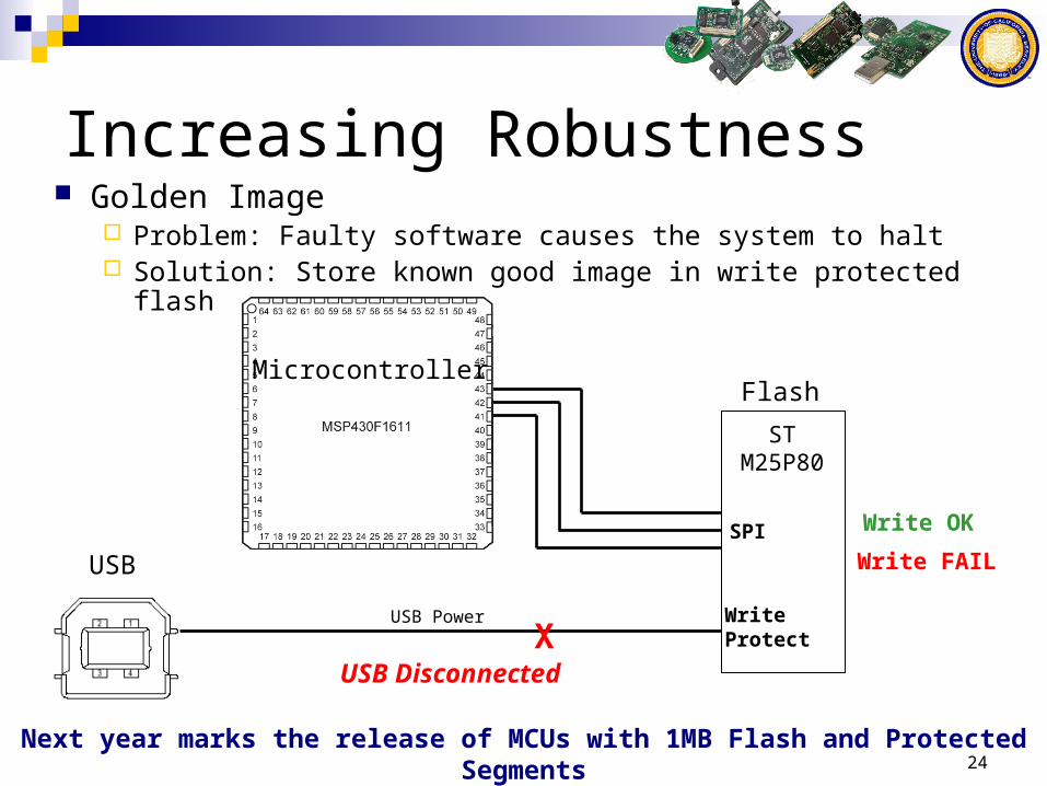
Increasing Robustness Golden Image
Problem: Faulty software causes the system to halt Solution: Store known good image in write protected flash
STM25P80
SPI
WriteProtect
MicrocontrollerFlash
USB
USB Power
Write OK
X
Write FAIL
USB Disconnected
Next year marks the release of MCUs with 1MB Flash and Protected Segments

25
Entering the Golden Image
Watchdog Count number of resets
Voltage Maintain a low power state
User Input Button presses
Other options Grenade timer (XSM/Trio)
26
Key Contributions
New design approach derived from our experience with resource constrained wireless sensor networks Active mode needs to run quickly to completion Wakeup time is crucial for low power operation
Wakeup time and sleep current set the minimum energy consumed Sleep most of the time
Principles for increased robustness Isolation: Fine grained software control Protected Golden Image Careful microcontroller/radio selection to meet app requirements

27
Want to experiment with Telos? Constraints:
Up to 4 powered hubs in a chain USB cables up to 5m in length Up to 127 devices on a USB bus
Practical testbed limits: 30m radius About a hundred motes Usable for a large room
Low cost approach Off the shelf hardware

28