detention basin design standards - pima...
TRANSCRIPT

June 2013
DETENTION BASIN DESIGN STANDARDS The following design standards apply when detention basins are proposed. Deviation from these standards requires written approval of the Floodplain Administrator. Additional standards to address specific site conditions may apply. These standards apply to Detention Basins without retention. If retention is proposed within a Detention Basin, design shall follow the standards in Section 5.6. Requirements for Drainage Report content are provided in Chapter 9, Drainage Report Content, and the required content for Development Plans and Plats is found in Chapter 10, Requirements for Plats, Development Plans. Required content for As‐Builts is described in Chapter 11, Required Content for As‐Built Certification and Plans. Typical details required on plans are provided in Appendix B. 4.1 Detention Basin General Requirements
1. Inspection and maintenance are required for all basins. An inspection and maintenance protocol including frequency of inspection, a checklist of items to be inspected, and recommended maintenance when an inspection identifies a maintenance requirement shall be prepared by an Arizona registrant. The protocol may be included in the project Drainage Report or prepared as a separate document. The protocol shall be reviewed and approved by the Floodplain Administrator prior to approval of the Tentative Plat or Development Plan. The protocol shall be delivered to the entity responsible for inspection and maintenance. An example of a detention basin inspection and maintenance checklist is provided in Appendix C.
2. To allow performance of inspection and maintenance, basins shall be legally and
physically accessible.
3. Upon completion of construction of all basins, an as‐built certification of the basin shall be prepared by an Arizona registrant and submitted to the Floodplain Administrator. The as‐built certification shall be used by the responsible party when performing periodic inspections and when restoring the basin to design specifications, if required.
4. Any modification of a basin, other than routine maintenance, that would affect volume
or performance requires a Floodplain Use Permit. 5. When detention basins are to be maintained by a private entity, such as a Homeowners
Association, this responsibility shall be described in the association’s Covenants, Conditions and Restrictions which shall refer to the inspection and Maintenance protocol and as‐built certification.

4.2 Dete
1. Aloto
2. Cis
3. O
F
4. WA
4.3 Dete
4.3.1 D
1. B
2. Ba
3. T
ato
T
ntion Basin
Although theots is encourowards redu
ounting rains prohibited.
On‐line detenloodplain Ad
Walls withinAdministrato
ntion Basin
Detention Ba
asins shall b
asins shall bpproximate
o allow mppurtenanceoes of emba
a. a greab. other
he measure
General Pro
use of stormraged, any reucing the req
nwater harve
ntion within dministrator
the basin r.
Location an
asin Location
be located w
be located topre‐develop
maintenancees, includingnkments, toater setback adequate a
ment from t
Figure 4
ohibitions
mwater and etention volquired deten
esting cister
regulatory fr.
are not a
nd Collection
n and Collec
ithin the pro
o ensure thaped flow con
e access, g basin outlo the projectis required tccess space
the outlet to
4.1 Minimum
rainwater hume on privntion volume
rn volume to
floodplains i
allowed, wit
n
ction Standa
oject bounda
at post‐devenditions whe
a minimumets (but nott boundary sto comply wexists adjac
o the propert
m Setback fro
harvesting favate residene for the pro
o reduce the
s prohibited
thout the a
ards
ary.
elopment floen flow exits
m 4‐foot st including oshall be provwith Section ent to the b
ty line is illu
m Property L
acilities on ptial lots shaoject.
e required d
d without th
approval of
ow depth, ws the project
setback frooutlet protevided, unless4.3.1.2, or asin, such as
strated in Fi
Line
rivate residell not be cou
detention vo
e approval o
f the Flood
width and vet boundary.
om basins ection) and os:
s right‐of‐wa
igure 4.1.
ential unted
olume
of the
dplain
locity
and outer
ay.
4. In subdivisions, detention basins shall be located in Common Area for Drainage.
5. Basins shall be located to avoid the use of embankments, if possible.
6. When basins are located to accept flows from predominantly natural areas, sediment
basins shall be required at the inlet. The configuration and volume of the sediment basin shall be determined by an engineer registered in the State of Arizona.
7. When basins are proposed to be located within a regulatory floodplain or erosion hazard area, it shall be demonstrated that the basin will mitigate local project flows during the 2‐, 10‐ and 100‐year storm events. Basins shall be designed to withstand all flood and erosion hazards.
4.3.2 Detention Basin Location and Collection Maintenance Requirements
1. Basins shall be maintained to perform as designed for the life of the project and shall
not be converted to a different use without a Floodplain Use Permit.
2. Inlet and outlet locations shall be maintained free of obstructions.
4.3.3 Detention Basin Location and Collection Prohibitions
1. Inlets or outlets which direct flow to a sidewalk or other paved pedestrian pathway shall include a scupper or other conveyance to prevent sidewalk or pathway overtopping by the 10‐year design discharge. Inlets or outlets shall not direct flow over a decomposed granite or other erodible pedestrian pathway.
2. Inlets or outlets shall not direct flow through a handicap accessible ramp or handicap
parking space.
3. Post‐development alterations that affect the function or design of drainage infrastructure are prohibited unless prior approval is obtained from the Floodplain Administrator. Alterations requiring approval include, but are not limited to, alteration of drainage structures, construction of new improvements and post‐development site grading which increases or causes flows to bypass the basin.
4.4 Detention Basin Depth and Freeboard
4.4.1 Detention Basin Depth and Freeboard Standards
1. Minimum freeboard shall be 6 inches within basins constructed below natural grade and 12 inches within basins designed with an embankment.

2. Fthw
3. T
th
4. B
ind
5. B
stst
4.4.2 D
1. T
m
2. Da
3. S
4.4.3 D
1. 1
A
reeboard is he basin bawithin weirs o
he water dehe 100‐year
asins shall hncorporated evice. The d
asins designteeper thanteeper than
Detention Ba
he depth omaintained.
Design volumbove the ele
lopes shall b
Detention Ba
00‐year waAdministrato
measured fnk, as showor spillways.
epth is measwater surfa
Figure 4.2
have a miniinto the we
device(s) sha
ned for 100‐n 4:1 shall h4:1. Security
asin Depth a
f the basin
me shall be evations sho
be maintaine
asin Depth P
ter depth sr.
from the 100wn in Figure.
sured from tce elevation
2 Basin Depth
mum of 1 seir or the siall be located
‐year water have a secuy barriers sh
and Freeboa
shall be in
restored wown on the b
ed to the orig
Prohibition
shall not ex
0‐year watee 4.2. The
the lowest en, as shown i
h and Freebo
sediment levde slope, ord where sed
depths of gurity barrier hall meet the
rd Maintena
nspected an
when the debasin as‐built
ginal design
xceed 6 fee
er surface elfreeboard r
elevation on in Figure 4.2
ard Requirem
vel measurer constructediment is like
greater thanat all locat
e requireme
ance Requir
nually to e
epth of sedit certificatio
configuratio
et, unless a
evation to trequirement
the basin fl2.
ments
ement deviced as a sepaely to accum
n 2 feet and tions wherents found in
rements
nsure the d
ment exceeon.
on.
approved by
the lowest tt does not a
oor to the t
ce, which caarate stand‐amulate.
with side se side slopen Section 4.1
design volum
eds 6” anyw
y the Flood
op of apply
op of
an be alone
lopes s are 11.
me is
where
dplain

4.5 Stora
4.5.1 St
1. Tast
2. Tthst
4.5.2 St
1. Bp
2. If
4
4.6 Basin
4.6.1 B
1. Tto
age Time
torage Time
he maximumcres in sizetormwater t
he maximumhan 10 acretormwater t
torage Time
asin bottomonding lastin
f an inspecti.5.1, the fola. Areasb. Compc. Basin d. Obstr
n Floor
Basin Floor S
he basin flooo the basin o
F
e Standards
m storage time is 12 houo be remove
m storage tis in size is 2o be remove
e Maintenan
ms shall be ng longer th
on identifielowing mainof ponding
pacted soil shoutlets shaluctions at th
tandards
or shall be goutlet, when
Figure 4.3 Ba
me for a basurs. The sted from the
me for a ba24 hours. Thed from the
nce Requirem
inspected an the limits
s evidence ntenance shashall be gradhall be scarifl be maintaihe outlet sha
graded to a mn no retentio
sin Floor Min
sin that intertorage timebasin.
sin that intehe storage tbasin.
ments
annually ans in Section 4
of ponding all be perforded to drainfied to promned to functall be remov
minimum sloon is provide
nimum Slope
rcepts runofe is defined
ercepts runotime is defin
nd after sto4.5.1.
lasting longrmed: n to the outlemote infiltrattion as desigved.
ope of 0.5%ed, as illustra
e for Positive
ff from a wad as the tim
off from a wned as the t
orm events
er than the
et, ion, gned, and
to provide ated in Figur
Drainage
atershed up me required
watershed grtime require
for evidenc
limits in Se
positive drare 4.3.
to 10 d for
eater ed for
ce of
ection
inage

2. The basin floor may be hydroseeded. If hydroseeding is proposed, plant species used in the seed mix shall be selected from the Approved Plant List provided in Appendix B of the Pima County Regulated Riparian Habitat Mitigation Standards and Implementation Guidelines available at: http://rfcd.pima.gov/wrd/riparian/pdfs/revised_guidelines_jan2010.pdf.
3. Other types of vegetation shall comply with Section 4.17.
4.6.2 Basin Floor Maintenance Requirements
1. The basin floor shall be inspected annually and after storm events to ensure that positive drainage is maintained for basins that do not include retention volume.
2. Maintenance shall be performed when accumulated sediment and debris alter the
design slope from the basin inlet to the basin outlet.
3. Invasive non‐native plants shall be removed. A list of the invasive non‐native plants can be found in Appendix E of the Pima County Regulated Riparian Habitat Mitigation Standards and Implementation Guidelines available at: http://rfcd.pima.gov/wrd/riparian/pdfs/revised_guidelines_jan2010.pdf.
4. Compacted soil shall be scarified to avoid areas of ponding and promote infiltration.
5. Soil with evidence of oil, grease or other chemicals shall be removed and disposed of
properly.
6. Debris and trash shall be removed from the basin at least annually.
4.6.3 Basin Floor Prohibitions
1. Except for paths within multi‐use basins, the use of decomposed granite or rock less than 4 inches in diameter on the basin floor is prohibited.
2. Invasive non‐native plants on the basin floor are prohibited, except for turf grass in
multi‐use basins. 4.7 Side Slopes
4.7.1 Side Slope Standards
1. Recommended side slope stabilization is presented in Table 4.1, or as otherwise specified in the geotechnical report.

Table 4.1 Side Slope Stabilization
Side Slope Ratio
Stabilization Method
3H:1V or flatter Approved Hydroseed Screened rock with minimal fines Dumped Riprap with Filter Fabric
no steeper than 2H:1V Hand Placed Riprap with Filter Fabric Gabion Mattress
no steeper than 1.5H:1V Articulated Revetment Units
no steeper than 1H:1V Grouted Riprap Concrete Lining with Welded Wire Fabric Gabions
steeper than 1H:1V Retaining Wall
2. The following standards apply to riprap side slope treatments:
a. Dumped riprap shall have a of at least 6 inches and be placed with a blanket thickness of 2 times the .
b. Hand placed or dumped riprap shall consist of hard, durable angular stone in erosive environments. In non‐erosive environments, non‐angular stone is allowed. Gradation shall be provided as described in Table 4.2.
Table 4.2 Dumped or Hand Placed Riprap Gradation
Dumped/Hand Placed Riprap Gradation
% Passing Size
100 – 90 2.00
85 ‐ 70 1.50
50 – 30 1.00
15 – 5 0.67
5 ‐ 0 0.33
c. Unless grouted, rock riprap shall be underlain with filter fabric. The filter fabric
shall be woven for a minimum of 2 feet into the upper end of the blanket and wrapped for a minimum of 2 feet around the riprap base of the blanket as illustrated in Figure 4.4.

3. W
wasa
4. W
thHh
4.7.2 S
1. Inh
2. S
3. W
fo
4. Fsh
d. Groutbe haone‐h
When a retaiwall shall beccompaniedaturated con
When hydroshe ApprovedHabitat Mitttp://rfcd.pi
ide Slope M
nspections sas not been
hould dama
When slope oundation so
ilter fabric thall be resto
Figure 4.4 Ri
ted riprap shrd, durable ahalf the grou
ning wall is e provided d by a reportnditions, sha
seed is usedd Plant List ptigation Stma.gov/wrd
Maintenance
hall occur adamaged by
ge be observ
treatment oil is lost or f
hat has migored to desig
iprap Blanket
hall be placeand hand‐emt depth.
proposed aswith the
t clearly statall be provide
as slope treprovided in tandards ad/riparian/pd
Requireme
nnually andy settling, ve
ved, basin si
is dumpedfilter fabric i
rated undergn specificat
t with Filter F
d on a groutmbedded int
s a basin sidDevelopmeing the assued and seale
eatment theAppendix Band Impledfs/revised_
nts
after stormegetation, er
ide slopes sh
d riprap, this exposed.
r the dumpeions.
Fabric End Tre
t bed at leasto the grout
e slope, stabnt Plan or umptions aboed by an Ariz
e seed mix sB of the Pimaementation _guidelines_
m events to rosion, or ot
hall be resto
he treatmen
ed rock ripra
eatment
st 6 inches tht bed to a m
bility design Tentative
out all soil pzona registra
shall have pla County ReGuidelines
_jan2010.pdf
ensure that ther causes.
ored to desig
nt shall be
ap layer or h
hick. Stonesinimum dep
for the retaPlat. A d
parameters uant.
lant species egulated Rips availablef.
slope treat
gn specificat
repaired w
has tears or
s shall pth of
aining detail, under
from parian e at
ment
ions.
when
holes

5. Grouted riprap side slopes shall be restored to design specifications when foundation soil is lost.
6. Retaining walls shall be restored to design specifications when signs of tipping, clogged
weep holes or soil subsidence are observed.
4.7.3 Side Slope Prohibitions
1. Free‐standing walls are not allowed as a basin side, without prior approval of the Floodplain Administrator.
2. Retaining walls greater than 4 feet measured from the top of the footing are not
allowed as a basin side, unless prior approval is obtained from the Floodplain Administrator.
3. Riprap that consists of rock that is not hard and durable is not allowed.
4. Invasive non‐native plants located on a basin side slope are not allowed. A list of the
invasive non‐native plants can be found in Appendix E of the Pima County Regulated Riparian Habitat Mitigation Standards and Implementation Guidelines available at: http://rfcd.pima.gov/wrd/riparian/pdfs/revised_guidelines_jan2010.pdf.
4.8 Inlet Structures
4.8.1 Inlet Structure Standards
1. The capacity of an inlet structure shall be determined by methods provided in: a. Drainage and Channel Design Standards for Local Drainage for Flood Plain
Management within Pima County, Arizona, b. The City of Tucson Standards Manual for Drainage Design and Floodplain
Management in Tucson, Arizona, or c. Other methods accepted by the Floodplain Administrator.
2. When flow crosses a sidewalk or other paved pedestrian pathway, a scupper or other
conveyance to prohibit overtopping of the 10‐year design discharge shall be used. Inlets shall not direct flow over a decomposed granite or other erodible pedestrian pathway.
3. When pipes are used as an inlet, the minimum size allowed is 12 inches.
4. Inlets shall have erosion protection with dimensions determined by the methods provided in the:
a. Drainage and Channel Design Standards for Local Drainage for Flood Plain Management within Pima County, Arizona,

5. T
sib
6. U
wmsh
Photo 4.or floor standardmaintain
Photothe b
b. The CMana
c. Federd. Other
he erosion pide slope to e level with
Unless groutewoven for a minimum of hown in Figu
1 shows a bnear the i
ds in this mned during th
o 4.2 illustrabasin inlet er
City of Tucsagement in Tal Highway Ar methods ac
protection sthe appropthe finished
ed, rock riprminimum of2 feet arouure 4.4.
asin inlet innlet, indicat
manual attemhe project lif
Phot
ates inadequrosion protec
son StandaTucson, ArizoAdministraticcepted by t
shall extend riate designd grade.
rap shall be f 2 feet intound the ripr
service whiting that anmpt to provfe.
to 4.1 Basin
uate riprap pction.
rds Manualona, ion, Hydraulthe Floodpla
below the fn depth. The
underlain wo the upsloprap base of
ich does notn adequatevide guidanc
n Inlet with R
placement re
l for Draina
lic Engineer in Administr
finished grae surface of
with filter fabe end of thethe blanket
t exhibit deg riprap trance for desig
Riprap Protec
esulting in er
age Design
Circular No.rator.
de of the baf the erosion
bric. The filte blanket ant on the do
gradation ofnsition wasgns which w
ction
rosion exten
and Flood
14; HEC‐14,
asin floor ann protection
ter fabric shand wrapped wn‐slope en
f the basin s provided. will remain
nding away f
dplain
, or
nd/or shall
all be for a nd as
lopes The well‐
from

4.8.2 In
1. In
o
2. Ssp
4.8.3 In
1. Insp
2. W
p
4.9 Outle
4.9.1 O
1. Ocoa
nlet Structur
nspections sbstructions
hould obstrpecifications
nlet Structur
nlets shall npace.
Water exceerohibited.
et Structures
Outlet Struct
Outlets shallompatible wdverse impa
Photo 4.2
re Maintena
shall occur aand not dam
ructions or s.
re Prohibitio
not direct fl
eding 12 inc
s
ture Standar
l be designwith the exact on surrou
Basin Inlet
ance Require
annually andmaged.
damage b
ons
ow through
ches in dep
rds
ned to ensuisting downunding prop
with Inadequ
ements
d after stor
be observed
h a handicap
pth at an in
ure that flonstream draerties.
uate Riprap P
m events to
d, inlets sh
p accessible
nlet located
ows exiting inage condi
Placement
o ensure th
hall be rest
e ramp or h
in a vehic
the projecitions and w
e inlet is fre
tored to d
handicap pa
cular use ar
ct boundarywill not hav
ee of
esign
arking
rea is
y are ve an
2. O2minap
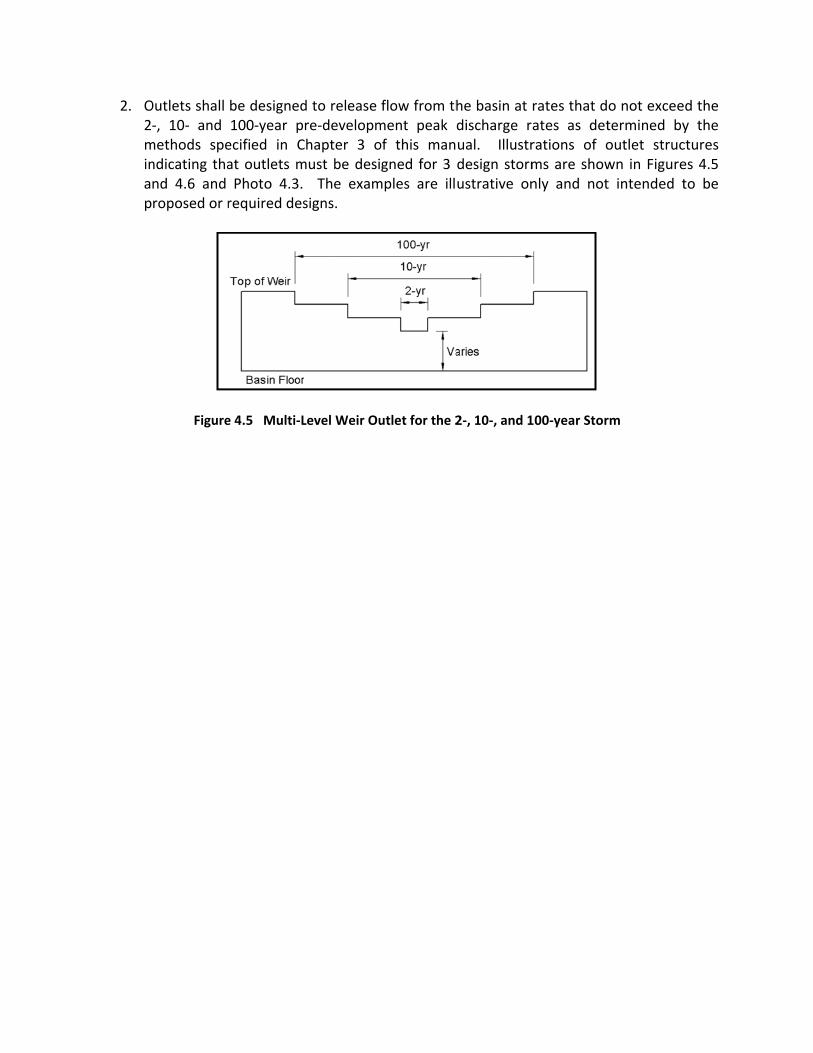
Outlets shall ‐, 10‐ and methods spendicating thand 4.6 and roposed or r
Figure
be designed100‐year pecified in Cat outlets mPhoto 4.3. required des
e 4.5 Multi‐L
d to release re‐developmChapter 3 omust be desi The exam
signs.
Level Weir Ou
flow from thment peak of this mangned for 3
mples are ill
utlet for the 2
he basin at discharge rual. Illustrdesign stormustrative on
2‐, 10‐, and 1
rates that dates as detrations of oms are shownly and not
100‐year Stor
o not exceetermined byoutlet strucwn in Figuret intended t
rm
d the y the ctures es 4.5 to be

Figure
Cro
e 4.6 Combin
Photo 4.3 Co
ss Section A‐A
ation Weir –
ombination W
– Culvert Outl
Weir Box
let
3. The capacity of outlet structures shall be determined using methods provided in:
a. Drainage and Channel Design Standards for Local Drainage for Flood Plain Management within Pima County, Arizona,
b. The City of Tucson Standards Manual for Drainage Design and Floodplain Management in Tucson, Arizona, or
c. Other methods accepted by the Floodplain Administrator.
4. Outlets which direct flow to a sidewalk or other paved pedestrian pathway shall include a scupper or other conveyance to prevent sidewalk or pathway overtopping by the 10‐year design discharge. Outlets shall not direct flow over a decomposed granite or other erodible pedestrian pathway.
5. Outlets shall have erosion protection with dimensions determined by the methods
provided in: a. Drainage and Channel Design Standards for Local Drainage for Flood Plain
Management within Pima County, Arizona, b. Federal Highway Administration, Hydraulic Engineer Circular No. 14; HEC‐14, or c. Other methods accepted by the District.
6. The erosion protection shall be placed beneath the finished grade of the downstream
side of the outlet to the appropriate design depth. The surface of the erosion protection shall be level with the finished grade.
7. Unless grouted, rock riprap shall be underlain with filter fabric. The filter fabric shall be
woven a minimum of 2 feet into the upslope end of the blanket and wrapped for a minimum of 2 feet around the riprap base of the blanket on the down‐slope end as shown in Figure 4.4.
4.9.2 Outlet Structure Maintenance Requirements
1. Inspections shall occur annually and after storm events to ensure the outlet and all components are free of obstructions and not damaged.
2. Should obstructions or damage be observed, outlets shall be restored to design
specifications.
4.9.3 Outlet Structure Prohibition
1. Outlets shall not direct flow to a handicap accessible ramp or handicap parking space.

4.10 Em An embaabove na
4.10.1
1. Weco
2. Win
3. E
w
4. Ee
bankments
ankment, foratural grade.
Embankme
When site combankmentonflicting co
When an emn the Drainag
a. The pdrainaprope
b. Expecc. Possib
failure
mbankmentwhichever is
mbankmentlevation in t
r the purpos. A typical e
Photo 4.4 E
ent Standard
onstraints prt is allowed. ode requirem
bankment isge Report dephysical envage paths, derty boundarcted flow conble effects te.
ts shall havgreater.
ts shall havehe basin.
es of this mambankment
mbankment
ds
revent a bas Site constra
ments.
s proposed, escribing at vironment ddrainage infry; nditions in thto public sa
ve a top w
e at least 1 f
anual, is a sit is illustrate
in a Resident
sin from beinaints include
the applicaleast the foldownstream frastructure
he event of afety and p
width of the
foot of freeb
de of a deteed in Photo 4
tial Subdivisi
ng constructe topograph
nt shall inclullowing: of the em, developed
embankmenproperty in
e 100‐year
board above
ention basin 4.4.
on Basin
ted entirely y, existing in
ude an emb
mbankment, d property,
nt failure; anthe event
ponding d
e the 100‐ye
constructed
below gradnfrastructure
bankment se
such as naand distanc
nd of embank
epth or 2
ear water su
d
de, an e and
ection
atural ce to
ment
feet,
urface

5. E
6. A
oe
7. W
p
8. Tep
Width, sp
9. W
mbankment
A minimum of Arizona, ombankment
When an outrovided as s
o allow mambankmentrovided, unla. a greab. other
pillway and s
When embana. An emb. The e
elevatc. The in
Figured. The d
year pbecausurfac
ts shall be co
of 6 inches, of in‐situ sot constructio
let is placedpecified by a
aintenance ts (not inclless: ater setback adequate a
setback mea
Fig
nkments are mergency spimergency stion, nvert and the 4.7, shall besign capacpeak discharuse it is at thce elevation
ompacted to
or depth reil beneath ton.
through anan Arizona r
access, a muding outle
is required tccess space
asurement a
ure 4.7 Emb
designed toillway shall bpillway inve
he downstree constructecity of the erge outflow he 100‐year used for rou
o at least 95%
commendedthe embank
embankmeregistered en
minimum 4‐et protectio
to comply wexists adjac
are illustrate
bankment Re
o impound gbe provided,ert elevation
eam side ofed of impervmergency sprate. The owater surfauting,
% of Standar
d by an engkment base
ent, an anti‐sngineer.
‐foot setbacon) to the
with Section ent to the b
d in Figure 4
equirements
reater than , n shall be at
f the emergvious materipillway shaloutlet will noace elevation
rd Proctor d
gineer registeshall be ex
seep collar o
ck from thproject bo
4.3.1.2, or asin, such as
4.7.
1 foot of wa
t the 100‐ye
gency spillwial, l be the preot be includn which is t
ensity.
ered in the xcavated pri
or equal , sh
e outer toeundary sha
s right‐of‐wa
ater,
ear water su
way, as show
e‐developed ed in the rohe highest w
State or to
all be
es of all be
ay.
urface
wn in
100‐outing water

e. The location of the emergency spillway shall not create any adverse impact to surrounding properties.
10. When an embankment is located within an erosion hazard setback or regulatory sheet
flood area, an engineering analysis shall be provided to determine erosion protection requirements which will protect the embankment from lateral migration of the watercourse.
11. A covenant which specifies, or Conditions, Covenants and Restrictions (CCR’s) which
include, inspection and maintenance responsibilities shall be recorded when a basin includes an embankment. An example covenant can be found in Appendix A. The covenant or CCR’s shall be reviewed and approved prior to approval of the Development Plan or Final Plat. Properly executed covenants shall be provided to the District for recording prior to approval of the Development Plan or Final Plat.
4.10.2 Embankment Maintenance Requirements
1. Inspections shall be conducted annually and after storm events to ensure the
embankment is not damaged due to erosion, piping, sliding, settling or other causes.
2. If damage to an embankment is observed, the embankment shall be restored to the design specifications.
4.10.3 Embankment Prohibition
1. Embankments that are classified as dams pursuant to Arizona Revised Statutes §45‐
1201 are prohibited. 4.11 Security Barrier
4.11.1 Security Barrier Standards
1. Basins designed for 100‐year water depths of more than 2 feet and with side slopes steeper than 4:1 shall have a security barrier at all locations where side slopes are steeper than 4:1.
2. Security barrier shall be a minimum of 42 inches high.
3. The security barrier shall consist of metal, masonry or a combination of the two,
meeting the minimum standards in the latest edition of the City of Tucson/Pima County Standard Details for Public Improvements.

4. When 100‐year water depths exceed 2 feet and pedestrian circulation occurs within 5 feet of the top of a basin, a security barrier shall be constructed. Pedestrian circulation includes ingress/egress to structures, sidewalks, parking or other accessory structures.
5. When vehicle maintenance access is required, a gate or bollards shall be provided at the
appropriate location.
4.11.2 Security Barrier Maintenance Requirements
1. Inspections shall be conducted annually to ensure the security barrier and surrounding grade are not damaged to the extent that the security of the basin is compromised.
2. If compromising damage is observed, the security barrier shall be restored to design
specifications.
4.11.3 Security Barrier Prohibitions
1. The use of vegetation as a security barrier is prohibited.
2. Security barriers shall not restrict the hydraulic capacity of basin inlet and outlet structures.
4.12 Perimeter Walls
4.12.1 Perimeter Wall Standards
1. When perimeter walls have openings that allow flow to enter into a basin, erosion protection that meets the minimum standards of Section 4.8 shall be provided.
2. When a wall is proposed within 5 feet of the horizontal location of the 100‐year water
depth, a report from an engineer registered in the State of Arizona shall be provided prior to approval of the Improvement Plan that contains at least the following:
a. The appropriate minimum setback from the top of slope, and b. Specific structural design requirements with details.
4.12.2 Perimeter Wall Maintenance Requirements
1. Inspections shall occur annually to ensure the perimeter wall and/or erosion at wall
openings are not adversely impacting the basin.
2. If adverse impacts are identified, the basin and/or wall shall be restored to the design specifications.

4.12.3 Perimeter Wall Prohibitions
1. Perimeter walls shall not block maintenance access.
2. Perimeter walls shall not restrict the hydraulic capacity of inlet or outlet structures. Perimeter walls are not allowed on embankments. 4.13 Underground Storage
4.13.1 Underground Storage Standards
1. Where underground storage is proposed, failure or blockage of the system shall not pose a hazard to public safety or property. Design considerations include underground storage location and emergency flow conveyance.
2. All stormwater collected during a storm event shall be removed within the disposal time
specified in Section 4.5.
3. Underground storage shall have inlets and outlets which meet the design standards found in Sections 4.8, 4.9 and 4.16.
4. Underground storage systems shall provide 1.5 times the required 100‐year detention
volume.
5. To provide for safe discharge of flow when the volume of an underground storage system is exceeded, an overflow outlet shall be provided which discharges to a drainage path which can convey flow away from structures, electrical equipment, pedestrian pathways, handicap‐accessible ramps, hazardous materials, and other areas where stormwater is likely to create damage to health, welfare or property.
6. A recorded covenant which specifies inspection and maintenance responsibilities is
required for an underground storage system. An example covenant can be found in Appendix A. The covenant shall be recorded prior to approval of the Development Plan or Final Plat, and the Sequence No. shall be provided on the Development Plan or Plat adjacent to the underground storage location on the plan view.
7. Prior to approval of the Tentative Plat or Development Plan, a report from an engineer
registered in the State of Arizona shall be provided that contains at least the following: a. Appropriate building setbacks from the underground storage system related to
structural integrity, b. Certification that the load bearing capacity of the soils underlying the
underground storage structure is adequate and the soil complex is appropriate bed material,

c. Structural design details, and d. Other design recommendations if appropriate.
4.13.2 Underground Storage Maintenance Requirements
1. Inspections shall occur annually and after storm events to ensure the underground
storage system is not damaged and is functioning as designed. Sufficient access for inspection shall be provided.
2. When an inspection reveals any of the following, the underground storage system shall
be restored to design specifications: a. Seepage, settlement, cracking, signs of improper joint alignment or displacement
of joints, b. Sediment accumulation, and c. Damage to or malfunction of pumps, valves, sumps, piping, manifolds or
appurtenances.
4.14 Setbacks
4.14.1 Setback Standards
1. For maintenance access, a minimum 4‐foot setback from basins and appurtenances, including basin outlets, outer toes of embankments, to the project boundary or to the limit of other access space shall be provided.
2. Because soil bearing capacity within a potential zone of saturation may be reduced,
structures shall be setback at least 15 feet from a basin, unless an appropriate alternative setback is justified by an engineer registered in the State of Arizona prior to approval of the Tentative Plat or Development Plan.
3. When a wall is proposed within 5 feet of the horizontal location of the 100‐year water
surface elevation, a report from an engineer registered in the State of Arizona shall be provided prior to approval of the Improvement Plan that contains at least the following:
a. The appropriate setback, and b. Specific structural design requirements with details.
4.14.2 Setback Prohibition
1. Structures, walls, or other obstructions are prohibited within maintenance access
setbacks. 4.15 Elevation Requirements

1. Any electrical equipment, excluding submersible pumps, within the basin shall be elevated 1 foot above the 100‐year water surface elevation of the basin, unless an engineer registered in the State of Arizona certifies that the electrical equipment when inundated does not pose any hazard to public health or safety.
4.15.1 Elevation Maintenance Requirements
1. Electrical equipment shall be inspected annually and maintained to ensure the 1‐foot
elevation above the 100‐year water surface has not been reduced. 4.16 Maintenance Access
4.16.1 Maintenance Access Standards
1. Maintenance access is required for all basins, and the access must be shown on the plans and described in the project drainage report.
2. In order to provide maintenance access, a minimum 4‐foot setback from basins and
appurtenances, outer toes of embankments, to the project boundary or to the limit of other access space, such as right‐of‐way, shall be provided. An example of a setback from a property line is shown in Figure 4.1.
4.16.2 Maintenance Access Maintenance Requirements
1. Inspections shall be conducted annually and after storm events to ensure access to the basin is not compromised.
4.16.3 Maintenance Access Prohibition
1. Obstruction of maintenance access or a maintenance access ramp is prohibited.
4.17 Landscaping Other Than Riparian Habitat Mitigation
4.17.1 Landscaping Standards
1. Vegetation may be planted on a basin floor or on a basin side slope that is 3:1 or flatter except in areas within a 20‐foot radius of the basin inlet, outlet or maintenance access ramp. Plants on the perimeter of a basin shall not obstruct drainage entering or exiting the basin.
2. Plants which can withstand inundation shall be selected.
3. Plants shall be spaced to allow access for maintenance.

4. Trees located adjacent to a required security barrier shall be placed an appropriate distance from the barrier to assure that the tree at maturity does not reduce the structural integrity of the security barrier.
5. Hydroseeding is allowed on the basin floor and 3:1 or flatter side slopes. Plant species
used in the seed mix shall be selected from the Approved Plant List provided in Appendix B of the Pima County Regulated Riparian Habitat Mitigation Standards and Implementation Guidelines available at: http://rfcd.pima.gov/wrd/riparian/guidelines/pdfs/onsite‐guidelines.pdf.
4.17.2 Landscaping Maintenance Requirements
1. Inspections shall occur annually and after storm events to ensure that landscaping has not impacted basin function.
2. If damage is observed, the basin shall be restored to design specifications.
3. Invasive non‐native plants shall be removed. A list of the invasive non‐native plants can
be found in Appendix E of the Pima County Regulated Riparian Habitat Mitigation Standards and Implementation Guidelines available at:
http://rfcd.pima.gov/wrd/riparian/guidelines/pdfs/onsite‐guidelines.pdf.
4. Any vegetation or debris within the 20‐foot radius described in Section 4.18.1. shall be removed.
4.17.3 Landscaping Prohibitions
1. Any vegetation within the 20‐foot radius described in Section 4.18.1 is prohibited.
2. Landscaping shall not be located within maintenance access ramps.
3. The use of decomposed granite or rock less than 4 inches in diameter on the basin floor
is prohibited, except paths within multi‐use basins.
4. Invasive non‐native plants located within a basin are not allowed, except turf grass within multi‐use basins.
4.18 Pumps
4.18.1 Pump Standards
1. The use of a pump may be allowed if site constraints prevent the basin from having positive drainage. Site constraints may include topography, existing infrastructure and
conflicting code requirements. Approval to use a pump shall be obtained from the Floodplain Administrator prior to the first submittal of the Tentative Plat or Development Plan.
2. If a pump is proposed, the detention system shall provide an emergency spillway
directed to a local watercourse that does not cause an adverse impact to the watercourse or neighboring properties and one of the following:
a. Additional basin volume to contain the entire volume of the 100‐year post‐developed hydrograph from the drainage area contributing to the basin, or
b. A back‐up pump with an emergency power source. If an emergency back‐up generator is proposed, the generator shall be elevated 1 foot above the 100‐year water surface considering total pump failure or shall be waterproofed.
3. Service equipment (excluding components whose design requires submersion) shall be
set at an elevation 1 foot above the unattenuated 100‐year water surface elevation, considering total failure of the pump system.
4. Outlets shall be designed to meet the requirements found in Section 4.9.
5. Pumps shall be in an accessible location for routine maintenance and emergency
service.
6. Basins with a pump shall meet the storage time standards found in Section 4.5.
7. The pump’s discharge rate shall not exceed the pre‐developed conditions 2‐year peak discharge rate.
8. The collection system shall discharge into a separate sump that screens the water
before entering the pump sump. The sump location and dimensions shall be shown on the plan set.
9. A clogging factor of 2.0 shall be used for the trash rack/screen design.
10. The pump shall be designed to pass 3‐inch solids.
11. A pump shall be provided with an automatic control switch with a vertical float
mechanism as well as a manual control.
12. A potable water supply with hose bibs shall be provided to aid in removal of silt and trash.
13. Each pump shall have an alarm system for high water and low water alarm with, at
minimum, the following: a. A light that provides a visual alert,

b. The name and phone number of a responsible party clearly displayed on the pump housing and alarm system,
c. Housing that is vandal proof and weather resistant, and d. Other Floodplain Administrator recommendations as appropriate.
14. A recorded covenant which specifies inspection and maintenance responsibilities is
required when a pump is used as a method of stormwater disposal. An example covenant can be found in Appendix A. The covenant shall be recorded prior to approval of the Development Plan or Final Plat, and the Sequence No. shall be provided on the Development Plan or Plat adjacent to the pump location on the plan view.
15. The project’s Drainage Report shall provide the following information:
a. Emergency back‐up plan, b. Drainage exhibit showing drainage flow under clogged conditions, c. Maintenance Plan with at minimum the following:
i. Maintenance schedule, ii. Type of maintenance activities, iii. Exhibit showing the location of the pump, alarm systems and other
equipment, and iv. Copy of the covenant.
16. A pump system analysis shall be submitted for Floodplain Administrator review and
approval with the Tentative Plat or Development Plan. The analysis shall include: a. Site Data
i. Contributing drainage area(s), ii. Location of outfall, iii. Capacity of outfall, and iv. Inflow hydrograph(s).
b. Pump System Components i. Specifications for the model and type of pump(s) proposed including
pump curves (single pump and parallel operation). Overloading the pump anywhere on the pump curve is not permitted,
ii. Location and specifications for intakes and catch basins, iii. Controls and alarm system, iv. Debris handling, v. Location of potable water supply, and vi. Location and design of emergency overflow.
c. Hydrologic/Hydraulic Analysis i. Headloss calculations for the entire system, including maximum and
minimum Total Dynamic Head (TDH) and flow rate, ii. Net positive suction head (NPSH) and pump level settings for on, off and
alarm positions, and iii. Inflow and outflow hydrographs and accumulated inflow and outflow
curves (mass flow curves). The use of HEC‐HMS is not appropriate for the

design of pump systems. A real‐time procedure which routes the design inflow hydrograph using pump on and off elevations and actual pump performance curves must be used.
4.18.2 Pump Maintenance Requirements
1. Inspections shall be conducted annually, after storm events and after the alarm system is activated to ensure the pump is not damaged and is functioning as designed.
2. Prior to the summer and winter rainy seasons, the pump, back‐up system and alarm
system shall be operated to ensure the system is functioning as designed.
3. If damage/malfunction is observed, the system shall be restored to design specifications.
4. Trash and debris shall be removed from the pump system and properly disposed.
5. The site layout shall consider adequate access for maintenance vehicles and removal of
equipment for repair. 4.19 Dry Wells
4.19.1 Dry Well Standards
1. When site constraints justify use of a dry well or dry wells to dispose of detention volume, approval to include a dry well or dry wells in basin design shall be obtained from the Floodplain Administrator prior to the first submittal of the Tentative Plat or Development Plan. When requesting the approval, the engineer must submit field investigation results and a preliminary site plan.
a. The field investigations shall include: i. Logs for soil borings to the anticipated depth of the dry well, ii. Determination of depth to groundwater in the proposed locations of dry
wells, and iii. A percolation testing report by an Arizona registered engineer. The
percolation testing report shall include the testing methods and results. b. The preliminary site plan shall include at minimum:
i. The location of the proposed dry well(s) and test well(s), ii. The location of the proposed structure(s) with the building footprint, iii. Parking lot layout including pedestrian circulation, and iv. The general drainage scheme.
Where dry wells are proposed as the sole method of outflow, the basin shall be designed to retain the total of the 100‐year storm.

2. Where a dry well is proposed, failure of the system shall not pose a hazard to public safety or property.
3. Dry wells shall be registered with the Arizona Department of Environmental Quality
(ADEQ) and designed, operated, and maintained in conformance with the most current ADEQ guidelines.
4. To obtain percolation rates to use in the design of the dry well(s) a percolation test shall
be performed to determine a stabilized infiltration rate.
5. Test results shall be de‐rated, using Equation 4.1, based on the in‐situ soil conditions. De‐rating is required to compensate for deterioration of the percolation capacity over time and to provide a factor of safety for silting and grate obstruction
4.1
Where: = the design percolation rate in inches/hour, = the measured stabilized percolation rate in inches/hour, and = the de‐rating factor.
a. The following de‐rating factors shall be used:
i. A de‐rating factor of 2 for coarse‐grained soils (cobbles, gravels and sands),
ii. A de‐rating factor of 3 for fine grained soils (silts and loams), and iii. A de‐rating factor of 5 for clay soils.
b. The design disposal rate for a dry well, after application of the de‐rating factor, should not be less than 0.1 cfs per well nor more than 0.5 cfs. Upon approval of performance, adjusted as presented above, a test well may then be used as one of the functioning dry wells for the project.
c. Drywells not performing to the original design standards shall be refurbished or replaced by the owner or a representative.
6. Dry wells shall be located into a permeable porous stratum to provide a minimum
distance of 10 feet between the water table or an impermeable layer and the base of the injection screen and shall be a minimum distance of 100 feet from any water supply well.
7. When dry wells are proposed, the basin floor shall be sloped to the dry wells at a minimum of 0.5% to assure that all wells are utilized for lower water levels.

8. Multiple drywells shall be spaced a minimum of 100 feet apart.
9. A dry well shall be located a minimum of 20 feet from the basin inlet.
10. If landscaping is proposed on the basin floor, the dry well inlet shall be raised 3 inches above the basin bottom elevation.
11. The dry well location shall be in an accessible location for routine maintenance and inspection and shall be protected from damage by vehicles.
12. The design of a dry well shall include provisions for trapping sediment within a settling
chamber.
13. The system shall use a floating absorbent blanket or pillow to enhance the removal of petroleum‐based organics floating on the water, and a hydrophobic petrochemical absorbent with a minimum capacity of 100 ounces per chamber shall be provided.
14. During site development, 1 dry well per basin shall be tested. All dry wells shall be
securely covered with filter cloth or other material to prevent silt infiltration during construction. Prior to Release of Assurances for plats and prior to Certificate of Occupancy for development plans, dry wells shall be re‐tested if a dry well has been compromised during construction. If the re‐test indicates reduced dry well performance, the dry well shall be restored to design specifications prior to Release of Assurances for plats or prior to Certificate of Occupancy for development plans.
15. Landscaping shall be installed a minimum of 4 feet from the perimeter of the bolted ring
and grate.
16. The words “Stormwater Only” shall be stamped in raised letters on the drywell grate.
17. A recorded covenant which specifies inspection and maintenance responsibilities is required when a dry well is used as a method of stormwater disposal. An example covenant can be found in Appendix A. The covenant shall be recorded prior to approval of the Development Plan or Final Plat, and the Sequence No. shall be provided on the Development Plan or Plat adjacent to the dry well location on the plan view.
18. A typical drywell installation is shown in Figure 4.8.

19. The project’s a. Plan f
functib. Maint
i. ii. iii.
Fig
Drainage Refor emergenon, tenance PlanMaintenanType of mExhibit sho
gure 4.8 Typic
eport shall pncy stormwa
n with at minnce scheduleaintenance aowing the lo
cal Dry Well I
provide the fater disposa
nimum the fe, activities, ocation(s) of
Installation
following infl in the eve
following:
the drywell
formation: nt the dryw
(s),
well(s) cease
(s) to

Contact information of the driller or authorized maintenanceprofessional, and
iv. A copy of the covenant.
4.19.2 Dry Well Maintenance Requirements
1. Inspections shall be conducted annually and after storm events to ensure the dry well and settling chamber are functioning as designed.
2. If an inspection identifies that the dry well is not infiltrating within the storage limits
outlined in Section 4.5.1, or other damage or maintenance requirements are identified, the maintenance shall be performed to restore the dry well(s) to design specifications.
3. Accumulated debris, weeds and trash shall be removed from the surface.
4. Sediment shall be removed from the settling chamber when approximately 50%of the
original volume of the chamber is filled.
5. All sediment removed from a settling chamber shall be disposed of at an authorized sanitary landfill.
6. Maintenance requirements shall be provided in the restrictive covenants for
subdivisions where dry wells are used.
4.19.3 Dry Well Prohibitions
1. Disposal methods using infiltration shall not be permitted for stormwater runoff which carries significant concentrations of sediment. This includes stormwater runoff flowing through sand bed channels, as well as stormwater runoff emanating from a predominantly natural watershed.
2. Dry wells are prohibited for industrial developments and other areas where hazardous
waterborne pollutants may enter a dry well.
3. In multi‐use basins, dry well inlets shall not pose a hazard to pedestrian safety.
4. Landscaping shall not impair dry well function.