development of shotcreting castable - ethesisethesis.nitrkl.ac.in/4867/1/211cr1268.pdf ·...
TRANSCRIPT
DEVELOPMENT OF SHOTCRETING
CASTABLE
A THESIS SUBMITTED IN PARTIAL FULFILLMENT
OF THE REQUIREMENT FOR THE DEGREE OF
MASTER OF TECHNOLOGY
In
Ceramic Engineering
By
MANDVI SAXENA
DEPARTMENT OF CERAMIC ENGINEERING
NATIONAL INSTITUTE OF TECHNOLOGY, ROURKELA
MAY 2013
DEVELOPMENT OF SHOTCRETING
CASTABLE
A THESIS SUBMITTED IN PARTIAL FULFILLMENT
OF THE REQUIREMENT FOR THE DEGREE OF
MASTER OF TECHNOLOGY
In
Ceramic Engineering
By
MANDVI SAXENA
Under the Guidance
of
Prof. Swadesh Kumar Pratihar &
Dr. Arup Kumar Samanta
DEPARTMENT OF CERAMIC ENGINEERING
NATIONAL INSTITUTE OF TECHNOLOGY, ROURKELA
MAY 2013
i
CERTIFICATE
This is to certify that the thesis entitled “DEVELOPMENT OF SHOTCRETING
CASTABLES” submitted by Miss Mandvi Saxena to the National Institute of Technology,
Rourkela in partial fulfilment of the requirements for the award of the degree of Master of
Technology in Ceramic Engineering is a record of bonafide research work carried out by her
under our supervision and guidance. Her thesis, in our opinion, is worthy of consideration for
the award of degree of Master of Technology in accordance with the regulations of the
institute.
The results embodied in this thesis have not been submitted to any other university or
institute for the award of a Degree.
Supervisor Supervisor
Prof. Swadesh Kumar Pratihar Dr. Arup Kumar Samanta
Department of Ceramic Engineering TRL Krosaki Refractories Limited
National Institute of Technology Belpahar
Rourkela
Department of Ceramic Engineering
NATIONAL INSTITUTE OF TECHNOLOGY,
ROURKELA
Orissa-769008
ii
ACKNOWLEDGEMENT
This report is the result of one year of work whereby I have been supported by many people.
It is a pleasant aspect that now I have the opportunity to express my deep gratitude for all of
them.
I take this great opportunity to express my thanks and deepest regard towards my supervisor
Prof. Swadesh Kumar Pratihar, Department of Ceramic Engineering, National Institute of
Technology, Rourkela and Dr. Arup Kumar Samanta, TRL Krosaki Refractories Limited,
Belpahar for their guidance and continuous support during research work and writing of this
thesis.
I also express my thanks to Dr. Sukumar. Adak, (Vice President, Technology, TRL Krosaki
Refractories Limited) for giving me to an opportunity to work at TRL Krosaki Refractories
Limited, Belpahar and providing me the necessary facilities. I also express my sincere thanks
to Miss. Smita Satpathy (Manager, TRL Krosaki Refractory Limited, Belpahar), for her
important suggestions and support during this work and her availability when I needed her
advises.
I am thankful to Prof. Sumit Pal (Faculty advisor) to for his valuable suggestions and help. I
am also thankful to Prof.J.Bera, Prof. H.S. Maity, Prof. S. Bhattacharya, Prof. B.B. Nayak,
Prof. D. Sarkar, Prof. R. Sarkar, Prof. R. Mazumder, Prof. S. Behera, Prof. Sudip Das Gupta,
Prof. Sunipa Bhattacharya and Prof. A. Chowdhury for their suggestions and support.
My heart feels great pleasure by remembering the time spent with my friends Tynee
Bhowmick, Gaurav K. Gugliani, Denny K. Philip, Aditya P. Shirimali, Uttam K. Chanda and
Subham Mahoto. It was a pleasurable experience to work with them.
No suitable words traced in the presently available vocabulary to express my full respect to
my Mom, Dad, and my family.
All other persons who helped me either in educational life or during the personal life I want
to say a single word “THANK YOU” which expresses all.
MANDVI SAXENA

iii
TABLE OF CONTENT:
Certificate i
Acknowledgement ii
Table of content iii
List of figures vi
List of tables ix
Abstract x
1. Introduction 1
2. Literature review 6
2.1. Castable refractory 7
2.2. Castable refractory composition 7
2.3. Binders 9
2.3.1. Calcium aluminate cement 9
2.3.2. Hydration of calcium aluminate cement 10
2.3.3. Dehydration of calcium aluminate cement hydrate 10
2.4. Fillers 11
2.5. Additives 11
2.5.1. Dispersant 12
2.5.2. Accelerator and Retarder 12
2.6. Classification of castable refractory 13
2.7. Role of particle size distribution of castable refectory 13
2.8. Low cement vibratable castable 18
2.9. Low cement self- flow castable 24
2.9.1. Rheology 27
2.10. Shotcreting Castable 28
3. Objective 33
4. Experimental work 35
4.1. Raw material 36
4.1.1. Particle size distribution of calcined alumina powder 36
4.2. Granulometric Calculation 36
4.3. Mixing procedure 37
iv
4.4. Flowability test 38
4.5. Sample preparation 39
4.5.1. Casting 39
4.5.2. Initial setting time 39
4.5.3. Drying of the castable 39
4.5.4. Firing of the castable 39
4.6. Characterization 40
4.7. Apparent porosity and bulk density 40
4.7.1. Cold crushing strength 40
4.7.2. Cold modulus of rapture 41
4.7.3. Permanent linear change 41
4.7.4. Phase analysis 42
5. Result and discussion 43
5.1. Study the effect of calcined alumina on 70% Al2O3 low cement
vibratable castable 44
5.1.1. Batch formulation of 70% Al2O3 low cement vibratable castable 44
5.1.2. Particle size and particle size distribution of calcined alumina 45
5.1.3. Initial setting time 46
5.1.4. Flow properties of 70% Al2O3 castables with adding different type of calcined
alumina 47
5.1.5. Flow decay 49
5.1.6. Apparent porosity and bulk density 50
5.1.7. Cold crushing strength 52
5.1.8. Cold modulus of rapture 54
5.1.9. Permanent linear change 55
5.1.10. Phase analysis (XRD) 56
5.2. Effect of amount of micro-silica on the properties of 70% Al2O3
self- flow low cement castable 58
5.2.1. Particle size distribution of the aggregates 58
5.2.2. Batch formulation of self- flow low cement 70% Al2O3 castable with
different micro-silica content 60
5.2.3. Setting time 60
5.2.4. Flow property 61
5.2.5. Apparent porosity and bulk density 62
v
5.2.6. Cold crushing strength 64
5.2.7. Cold modulus of rapture 65
5.2.8. Permanent linear change 67
5.2.9. Phase analysis 67
5.3. Effect of amount of calcined alumina in 70% Al2O3 self- flow low
cement castable 69
5.3.1. Batch formulation of self- flow low cement 70% Al2O3 castable with
different calcined alumina content 70
5.3.2. Setting time 70
5.3.3. Flow property 71
5.3.4. Apparent porosity and bulk density 72
5.3.5. Cold crushing strength 74
5.3.6. Cold modulus of rapture 75
5.3.7. Permanent linear change 77
5.3.8. Phase analysis 77
5.4. Effect of amount of accelerator on properties of 70% AL2O3 low
cement self flow castable 79
5.4.1. Batch formulation of low cement self flow castable as a function of setting
Accelerator 79
5.4.2. Setting time 81
5.4.3. Apparent porosity and bulk density 82
5.4.4. Cold crushing strength 84
5.4.5. Cold modulus of rapture 85
5.4.6. Permanent linear change 86
5.4.7. Phase analysis 86
6. Conclusions 91
7. References 94
vi
LIST OF FIGURES:
Fig. 4.1 Photo graph of laboratory Hobart mixture used in the present study 37
Fig. 4.2 Photo graph of flow cone described by ASTM C230 38
Fig. 5.1 Particle size distribution of calcined alumina of Alumina-1, alumina-2,
Alumina-3 and Alumina-4
45
Fig. 5.2 Initial setting time of castable as a function of calcined alumina type 46
Fig. 5.3 Variation of vibro-flow of the 70% Al2O3 low cement vibratable castable as
a function of calcined alumina type with 5% water
48
Fig. 5.4 Variation of flow decay of the 70% Al2O3 low cement vibratable castable as
a function of calcined alumina and time
49
Fig. 5.5 Variation of apparent porosity of the low cement vibratable castable as a
function of calcined alumina and temperature
50
Fig. 5.6 Variation of bulk density as a function of calcined alumina and temperature 51
Fig. 5.7 Variation of cold crushing strength as a function of calcined alumina and
temperature
53
Fig. 5.8 Variation of cold modulus of rapture as a function of calcined alumina and
temperature
54
Fig. 5.9 Variation of Permanent Linear change as a function of calcined alumina at
1400OC and 1500OC
55
Fig. 5.10 XRD pattern of the Vibratable 70% Al2O3 low cement castable fired at 57
vii
different temperatures for (a) MR30, (b) CL370, (c) CT9FG and (d) GA4R
Fig. 5.11 Setting time of castable as a function of micro-silica content 60
Fig. 5.12 Required water as a function of micro-silica content to achieve 100% flow 61
Fig. 5.13 Apparent porosity of low cement self- flow castable as a function
temperature and micro-silica content
62
Fig. 5.14 Bulk density of low cement self- flow castable as a function temperature and
micro-silica content
63
Fig. 5.15 Cold crushing strength of low cement self- flow castable as a function
temperature and micro-silica content
64
Fig. 5.16 Cold modulus of rapture of low cement self- flow castable as a function
temperature and micro-silica content
65
Fig. 5.17 XRD pattern of the self- flow low cement castable fired at different
temperature for (a) 6% micro-silica, (b) 8% micro-silica, (c) 10% micro-silica and (d)
12% micro-silica containing castable
67
Fig. 5.18 Setting time as a function of calcined alumina content 70
Fig. 5.19 Required water of low cement self- flow castable as a function of calcined
alumina content to achieve 100% flow
71
Fig. 5.20 Apparent porosity as a function of calcined alumina and temperature 72
Fig. 5.21 Bulk density of low cement self- flow castable as a function of calcined
alumina and temperature
73
Fig. 5.22 Cold crushing strength of low cement self- flow castable as a function of
calcined alumina and temperature
74
Fig. 5.23 Cold modulus of rapture of low cement self- flow castable as a function of
calcined alumina and temperature
77
Fig. 5.24 XRD pattern of the self- flow low cement castable fired at different 78
viii
temperature for (a) 6% calcined alumina, (b) 8% calcined alumina, (c) 10% calcined
alumina and (d) 12% calcined alumina containing castable
Fig. 5.25 Setting time verses amount of additive 79
Fig. 5.26 Apparent porosity as a function of water glass and temperature 82
Fig. 5.27 Bulk density as a function of water glass and temperature 83
Fig. 5.28 Cold crushing strength as a function of water glass and temperature 84
Fig. 5.29 Cold modulus of rapture as a function of water glass and temperature 85
Fig. 5.30 XRD pattern of the self- flow low cement castable fired at different
temperature for (a) 0.1% sodium silicate, (b) 0.15% sodium silicate, (c) 0.25%
sodium silicate and (d) 0.5% sodium silicate containing castable
87
ix
LIST OF TABLES:
Table II.I Batch formulation of refractory castable 8
Table II.II Composition and service temperature of different aggregate 8
Table II.III Hydration reaction for monocalcium aluminate with respect to
temperature and time
10
Table V.I Physical and chemical properties of calcined alumina 45
Table V.II Batch formulation of low cement vibratable castable 45
Table V.III Semi-quantitative analysis of the phases present in the sample
sintered at different temperature
57
Table V.IV Calculation of particle size distribution of the aggregates 59
Table V.V Batch formulation of self- flow low cement castable with different
Micro-silica content
60
Table V.VI Permanent linear change of self- flow castable as a function of
micro-silica
67
Table V.VII Semi-quantative analysis of the phases present in the sample
sintered at 1100, 1400 and 1500oC:
69
Table V.VIII Batch formulation of self- flow low cement castable with
different calcined alumina content
70
Table V.IX Permanent linear change of self- flow castable as a function of
calcined alumina
77
Table V.X Semi-quantitative analysis of sample fired as a function of
calcined alumina
79
Table V.XI Batch formulation for low cement self flow castable as a
function of setting accelerator
80
Table V.XII Permanent linear change of castable as a function of accelerator 86
Table V.XIII Semi-quantitative analysis of sample fired at 1400 and 1500oC
as a function of water glass
87

x
ABSTRACT
Particle packing is one of important parameters, which dictates physical and thermo-
mechanical properties of refractories. Fillers play a substantial role in the packing behaviour
of low cement castable. Fine filler particles fill the voids of the castable aggregate leading to
a high packing density of the castable and thereby decrease the cement as well as water
requirement of the castable. Micro-silica and calcined alumina are normally used as filler
materials in the development of low cement castable. It has been established that these fine
fillers particles are responsible to provide ceramic bond and the intermediate temperature and
provides high strength at high temperature due to formation of secondary mullite. In the
present work an attempt has been made to develop low cement castable with suitable filler
addition. Effect of particle size and particle size distribution of calcined alumina filler has
been studied in order to achieve high flow behaviour in low cement 70% alumina based
vibratable castable formulation. This alumina filler particle has further been used to optimize
and develop a suitable self- flow castable, wherein the amount of micro-silica and calcined
alumina amount has been optimized. Physical and thermo-mechanical properties of the
castables thus developed have also been studied in detail. Attempt has also been made to
study the effect of setting accelerator amount on the properties of self- flow castable thus
developed with an aim for shotcreating application.

1
CHAPTER-I
INTRODUCTION
2
1. INTRODUCTION
Monolithic or unshaped refractories namely, castables, gunning mixes, ramming mass,
morters etc. has advantages form the point of view of application and performances over
shaped refractories. Major advantage of monolithic refractory is that it makes joint less
structure so that it shows high corrosion and erosion resistance. Monolithic refectories not
required shaping and firing, so that significant amount of energy is saved also complicated
shapes are prepared. Early development of monolithic refractories lies with the development
of conventional castables. Conventional castable made with the combination of aggregate and
high alumina cement binders. Earlier work shows that particle size distribution of aggregate
for conventional castable had distribution coefficient 0.33 to 0.26. Cement content in
conventional castable is around 15-20%. Water requirement to provide suitable rheology for
casting is of the order of 10% as it contains high amount cement. The required water is
utilized for i) fill up the porosity within the aggregates, ii) hydration of cement binders and
iii) provides improved flowability through wetting the aggregates surface . Room temperature
strength of conventional castables is due to the hydraulic bond formed by hydration of
cement. However, these hydraulic bonds dissociates at intermediate temperature zone due to
de-hydroxylation of cement hydrates. These leads to a substantial increase in porosity and
consequent decrease in strength of the castable in the intermediate temperature range. Among
the several other disadvantage of conventional castable, the high CaO content in the
composition is of importance as it may form some calcium-alumino-silicate glass, which
substantially reduces themo-mechanical properties of the castable. These problems associated
with conventional castable could be reduced by lowering the cement content.
In early 80’S, development of low cement castable (LCC) has made remarkable improvement
on the development and application of monolithic refractories. Development of LCC lies with
3
the partial substitution of high alumina cement binder of conventional castable with some
filler material like micro-silica and calcined alumina. Filler materials fill the voids between
the aggregate, there by reduces the water requirement. Micro-fine filler materials reduce the
cement content and increase the initial packing density of the castable. Theoretically,
composition with high packing density requires low amount of water as comparison to
castable had improper packing as a result mechanical and physical properties of the castable
improves. Micro-silica and calcined alumina has small particle size in range of microns.
Hence form ceramic bond at intermediate temperature and increases the strength of the
castable at intermediate temperature. Further, reduced the cement content has been taken care
off in the development of ultra- low cement castable; no cement castable, chemical bonded
castable wherein different types of binders like hydraulic alumina, clay, silica sol, and
alumina sol etc has been used as a replacement of cement bond.
Low cement castable, ultra low cement castable etc. have some disadvantages like it shows
poor flow behaviour. The vibration and a suitable mould are required for placement of low
cement castable on refractory lining. Application of these castables requires high men
powder. To overcome the mould requirement gunning technology has been adopted. The
composition of gunning mass is similar to that of the vibratable castable except the addition
of a quick setting. In this technique dry mix of castable pump in to the pipe to the nozzle.
Water and setting additive is mixed at nozzle and spray by air pressure which sticks at lining
surface.
In order to overcome the problem associated with the vibration during application of LCC
researchers and scientists have been working around the globe to develop self- flow castable.
Self- flow castable, flow of castable takes place under the action of gravity. For self- flow
castable, mix has to be dispersed properly. Flow behaviour depends on the particle size
distribution of the aggregate. It has been well established that for self- flow castable
4
distribution coefficient of the aggregate has to be in the range of 0.21 to 0.25. As distribution
coefficient decreases, the amount of fines in the castable composition also increases. For
good flow dispersion of the particle is an important criteria. Fine powder shows tendency of
agglomeration and coarse particle shows friction that hindered the flow. Fine powder
increases the separation between the coarse aggregates that reduce the friction effect and thus
flow increases.
Self- flow castable had a disadvantage, which is the requirement of a mould for placing the
castable in to the furnace lining. In the 1990s, another application technique has been adopted
for placing the castable on the furnace lining known as shotcreting technique. In shotcreting,
self- flow castable with 100% flow value pumped in to the pipe line to the nozzle. At nozzle
castable mixed with setting accelerator and spray in to the application area. The advantages
of shotcreting over gunning technique that, in shotcreting, castable was premixed with water
to gets homogeneous mixture that gave homogeneous properties but in case of gunning water
was added at nozzle, there is lack of homogenization of mixture that decreased the property
of the gunning mix. Due to lack of homogenization and mixing dust releases at nozzle point
also shows high rebound loss. Shotcreting shows good lining, without any lamination and
voids structure with good mechanical and physical properties.
The present study aimed to develop a 70% Al2O3 shortcreting castable. The study has been
carried out in three phases. The effect of particle size and particle size distribution of filler
calcined alumina has been studied in order to achieve a good flow behaviour in vibro-flow
LCC castable in Phase I. Self- flow castable has been developed with the optimized calcined
alumina and the effect of amount of micro-silica and calcined alumina has been studied in
order to get 100% flow with minimum amount of water requirement in Stage II. In the third
phase an attempt has been made to develop a self- flow castable with a suitable setting
5
accelerator with a aim for shortcreting application. Physical and mechanical properties of the
castable developed in each step has been characterized in detail.
The present thesis has been divided into six chapters. Chapter I give a brief introduction of
the thesis, chapter II detailed a comprehensive literature review of the subject. Objective of
the present work has been written in chapter III and chapter IV detailed the experimental
technique adopted in the present study. Results and discussion on the present study has been
included in chapter V. Finally Chapter VI summarizes the conclusions of the present study.
6
CHAPTER-II
LITERATURE REVIEW
7
2. LITERATURE REVIEW
2.1 Castable Refractory
The past two decade had witnesses the remarkable improvement in unshaped refractory over
shaped refractory, both in preparation and application technology. The unshaped refractory
had superior properties in terms of labour productivity, installation efficiency, adaptability,
energy saving, joint less, service life, etc over shaped refractory. Monolithic refractory have
increasingly been used, especially in metallurgical furnace in place of shaped refractory [1,2].
Unshaped refractory are generally classified on the basis of their method of use in variety of
application. Classifications of monolithic refractory are given below [3].
i) Conventional castable refractory
ii) Pumpable refractory,
iii) Injectable refractory,
iv) Plastic mass refractory
v) Ramming mass refractory
vi) Gunning mass refractory
vii) Dry vibratables
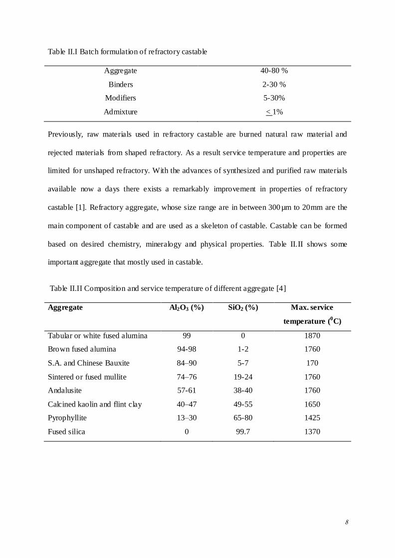
2.2 Castable Refractory Composition
Castable Refractories are premixed combination of aggregate, matrix component, binder and
admixture. The batch formulation of refractories castable and their required percentages are
shown in Table II.I [4].
8
Table II.I Batch formulation of refractory castable
Aggregate 40-80 %
Binders 2-30 %
Modifiers 5-30%
Admixture < 1%
Previously, raw materials used in refractory castable are burned natural raw material and
rejected materials from shaped refractory. As a result service temperature and properties are
limited for unshaped refractory. With the advances of synthesized and purified raw materials
available now a days there exists a remarkably improvement in properties of refractory
castable [1]. Refractory aggregate, whose size range are in between 300µm to 20mm are the
main component of castable and are used as a skeleton of castable. Castable can be formed
based on desired chemistry, mineralogy and physical properties. Table II.II shows some
important aggregate that mostly used in castable.
Table II.II Composition and service temperature of different aggregate [4]
Aggregate Al2O3 (%) SiO2 (%) Max. service
temperature (0C)
Tabular or white fused alumina 99 0 1870
Brown fused alumina 94-98 1-2 1760
S.A. and Chinese Bauxite 84–90 5-7 170
Sintered or fused mullite 74–76 19-24 1760
Andalusite 57-61 38-40 1760
Calcined kaolin and flint clay 40–47 49-55 1650
Pyrophyllite 13–30 65-80 1425
Fused silica 0 99.7 1370

9
2.3 Binders
In alumina–silicate castable system, with the development of high alumina cement, calcium
aluminate cement is used as a principal binding agent. Past 20 years, special castables have
been developed using non cement binder such as hydraulic alumina, clay, silica, and alumina
gel. On the other hand some other chemical binders have also been considered over past few
years. Chemical binder for monolithic refractories can be classified into two groups;
inorganic and organic. Inorganic binders contain some impurity which is harmful for
monolithic refractory at high temperature [1, 4].
2.3.1 Calcium aluminate cement
Calcium aluminate cement (CAC) containing castables had a rich history of over 80 years.
Involvement of CAC in castables refractories had been coming from conventional castables
to ultra-low cement castables. CAC contain different phases such as C12A7, CA, CA2, CA6
based on CaO and Al2O3 ratio, among these calcium monoaluminate (CA) and calcium
dialuminate (CA2) are most important phases for castables manufacturing. Calcium
monoaluminate (CaO.Al2O3) has high melting point (1600OC) and developed high strength
during short time. Whereas, CA2 is a secondary phase in CAC’s and has higher melting point
(1700-1765OC) than CA phase but requires more time to set due to its low hydraulic activity.
Hydraulic activity of CAC decreased with increasing Al2O3/CaO ratio. CAC contain
impurities such as rich iron and high silica because of these impurities, CAC contain C4AF,
C2S and C2AS phases. C2AS (gehlenite) is an undesirable phase as it might decrease the
refractoriness of castable [5, 6].
10
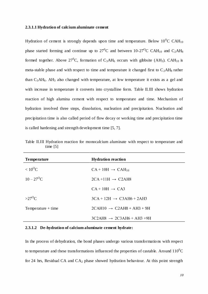
2.3.1.1 Hydration of calcium aluminate cement
Hydration of cement is strongly depends upon time and temperature. Below 100C CAH10
phase started forming and continue up to 270C and between 10-27OC CAH10 and C2AH8
formed together. Above 270C, formation of C3AH6 occurs with gibbsite (AH3). CAH10 is
meta-stable phase and with respect to time and temperature it changed first to C2AH8 rather
than C3AH6. AH3 also changed with temperature, at low temperature it exists as a gel and
with increase in temperature it converts into crystalline form. Table II.III shows hydration
reaction of high alumina cement with respect to temperature and time. Mechanism of
hydration involved three steps, dissolution, nucleation and precipitation. Nucleation and
precipitation time is also called period of flow decay or working time and precipitation time
is called hardening and strength development time [5, 7].
Table II.III Hydration reaction for monocalcium aluminate with respect to temperature and time [5]
Temperature Hydration reaction
< 10OC CA + 10H → CAH10
10 – 27OC 2CA +11H → C2AH8
CA + 10H → CA3
>27OC 3CA + 12H → C3AH6 + 2AH3
Temperature + time 2CAH10 → C2AH8 + AH3 + 9H
3C2AH8 → 2C3AH6 + AH3 +9H
2.3.1.2 De-hydration of calcium aluminate cement hydrate:
In the process of dehydration, the bond phases undergo various transformatio ns with respect
to temperature and these transformations influenced the properties of castable. Around 1100C
for 24 hrs, Residual CA and CA2 phase showed hydration behaviour. At this point strength

11
has maximum value. Between 100-400OC, AH3 and C3AH6 decompose into amorphous
anhydrous and water vapour remove and strength decreased due to porosity increased around
13 to 17%. C3AH6 continue to dehydrate to C12A7H at 400 - 900OC and porosity increased
around 23%. Cement phase re-crystallize in to C12A7 than CA at 800 – 1100OC, at this time
porosity reaches maximum value around 25%. At temperature around 1100 to 1300OC, 30%
CA2 phase formed and above 1300OC CA6 phase formed from CA2 [5].
2.4 Fillers
Conventional castable contain high amount of cement that’s why it required maximum
amount of water. To decrease cement content, modifiers were added. These modifiers filled
the voids between the aggregate, so that porosity decreased as well as amount of cement
required. With decreasing cement contain, water requirement also decreased. Clay, kaolin
dust, micro-silica, micro-chromite, reactive alumina etc. are used as a modifiers. Among
these fines particles, micro-silica and reactive alumina are most common modifiers. The size
of micro-silica and reactive alumina is around 0.2-0.5µm and 1-10µm respectively. At high
temperature they react each other or with the matrix and form mullite phase which imparts
high strength [26,8].
2.5 Additives
Additives or admixture are widely used in unshaped refractory. These additives modifies
several physical properties of the castables namely workability, setting time etc. and thereby
the performance of castable. They are divided into many groups based on their work in
castable such as; additives give effect on workability (dispersant, plasticizer etc), also
changed their setting time (accelerator and retarder) and improve their performance at
application area (sintering aid, anti-explosion agent and anti-oxidant etc) [1, 9].

12
2.5.1 Dispersant
Dispersion of particles plays a vital role in the development of castable refractory. Absence
of particle dispersion causes agglomeration of the particles because of Vander Waals
attractive force. Because of agglomeration viscosity of castable increased therefore, large
amount of water is required to increase flowability of the castable [4]. To prevent the
agglomeration, there are three mechanism to disperse the particle in the suspension, these are;
electrostatic, steric and electrosteric stabilization. Refractory castables are usually dispersed
through the electrostatic mechanism. In electrostatic mechanism, the repulsion generated
between the particles due to electrostatic charge on the particle. These dispersant are
multivalent anions. These ions absorbed on the particle surface and create electric charge on
the particles. The presence of the counter ions creates an electric double layer which in turns
increases the repulsion force and also increases the Zeta potential of the oxide grains in the
castable. The repulsion between electric double layers overcome the Vander Waals attractive
force and prevents agglomeration and flocculation of the particles in a castable system [10].
2.5.2 Accelerator and Retarder
There are many installation technologies that required quick setting, like gunning and
shotcreting. Accelerator is used to give flash setting of castable. Setting additives or
accelerators are classified in three groups; inorganic (sodium silicate, calcium chloride etc);
organic polyelectrolyte (sodium polyacrilate) and viscosity enhancing polymer (hydroxyethyl
cellulose). Inorganic admixture increased ionic strength of system and increased particle
attraction and agglomeration. Organic polyelectrolyte has high molecular weight and creates
bridge between the particles. Hydroxyethyl cellulose type polymers are water soluble, non-
ionic and semi-synthetic that generates a thixotropic lubricant gel and increased liquid
13
viscosity [11]. Retarder used to increase the setting time of castable. Citric acid is good
retarder also shows water reduction and increasing the setting time.
2.6 Classification of Castable Refractory
Castables can be classified on the basis of cement content and their placement method such
as some castables are applied on application area with the help of external energy (vibration)
and some are without it. The classifications of castable are given below [4].
1) CaO content
Conventional castable → 15-35% cement
Cement Castable → 5-8% cement
Ultra low cement Castable → 2-3% cement
No cement castable → <1% cement
2) Flow/placement method
Vibratable
Self- flow
Shotcreting
Gunning
2.7 Role of Paticle Size Distribution in Refractory Castable
Particle size distribution (PSD) play important role in castable refectory because of two
reasons. These reasons are given below [12].
1) To achieve an optimum packing and good flowability with low water percentage.
2) PSD also indicates that the castable is either vibratable or self- flow.
14
Particle size distribution also affects the rheological behaviour of castable during installation
in application area. In order to achieve good particle size distribution there are two packing
methods; gap sizing and continuous sizing. In gap sizing, there are more than two graded
aggregates mixtures are used to achieve high packing density but it has a disadvantage that it
has low flowability. However, most ceramic castables are fabricated by continuous particle
size distribution [4]. In continuous distribution, particles are distributed from some maximum
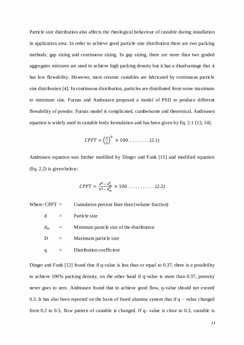
to minimum size. Furnas and Andreasen proposed a model of PSD to produce different
flowability of powder. Furnas model is complicated, cumbersome and theoretical. Andreasen
equation is widely used in castable body formulation and has been given by Eq. 2.1 [13, 14].
. . . . . . . . . (2.1)
Andreasen equation was further modified by Dinger and Funk [15] and modified equation
(Eq. 2.2) is given below:
. . . . . . . . . . . (2.2)
Where: CPFT = Cumulative percent finer than (volume fraction)
d = Particle size
dm = Minimum panicle size of the distribution
D = Maximum particle size
q = Distribution coefficient
Dinger and Funk [12] found that if q-value is less than or equal to 0.37, there is a possibility
to achieve 100% packing density, on the other hand if q-value is more than 0.37, porosity
never goes to zero. Andreasen found that to achieve good flow, q-value should not exceed
0.3. It has also been reported on the basis of fused alumina system that if q – value changed
from 0.2 to 0.3, flow pattern of castable is changed. If q- value is close to 0.3, castable is
15
vibratable and if it is less than 0.25, castable shows self- flow properties. The q-value
indicates the amount of fine content in the castable aggregate formulation. If q-value
decreased, there is increased in the amount of fine content in the castable and this fine content
helps in filling the voids and also create separation among aggregate thereby, promoting good
flow of the castable.
Low cement castable is divided into two groups on the basis of q-value and that division is
given below:
Vibratable castable
Self- flow castable
S. Ganguli et. al. [16] prepared 80% Al2O3 based low cement castable with varying q-value
from 0.25 to 0.33. It has been observed that q- value 0.31 required low amount of water as
compared to other. It could be correlated with loose filled density (LFD) of the castable.
Castable prepared with q-value 0.31 had high LFD. So that castable had q-value 0.31 had
better packing as compared to other. Castable prepared with q-value had high flow value,
high apparent porosity, Bulk density, CCS, CMOR and HMOR. It could be also correlated
with LFD of the castable.
Bjorn Myhre [17] prepared castables with white fuse alumina, calcined alumina and micro-
silica with q- value 0.37 and 0.26. It has been observed that q-value 0.37 required high
amount of water and micro-silica as comparison to q-value 0.26 to achieve high flow value.
Castable with q-value 0.26 had high amount of fines, that fines create separation between
particles and increase the flow value of the castable. It has also been reported that as the
percentage of micro-silica increases the flow value at a low water percentage.
16
Y. Kutmen Kalpakli [18] studied the effect of particle size distribution on the physical,
chemical properties and corrosion mechanism of ultra- low cement castable. Superfine
(<0.04µm) fraction of reactive alumina, calcined alumina, silica fume and calcium aluminate
cement has been used as additives. Particle size distribution coefficient q-value has been
varied in the range 0.21-0.26 with a step of 0.01 for the formulation of the castable batches.
The water requirement of the castables was reported to increase in q-value of the castable.
This phenomenon has been attributed with the fact that with decreasing q-value specific
surface area of the particle increased therefore, less water is required. Bulk density and cold
crushing strength increased with increasing in q-value.
E. Karadeniz et. al. [19] prepared low cement self- flow castable with varying q-value from
0.2 to 0.25. It could be observed that castable prepared with q- value 0.23 shows high self-
flow value as compared to other. It could be due to castable with q-value 0.23 had high initial
packing density so that it required low amount of water that give better flow. It could also
observe that fines powder created the gap between the particles and reduced the friction low
between the grains and increase the flow.
Toshisiko Kando et. al. [20] stuided the relationship between grain size distribution and
fluidity of castable. The castables has been prepared with coarse grain (6-2.5mm), medium
grain (2.5 -1mm) and fine <1mm. It has been reported that castables castables prepared with
coarse and fine aggregates equal to 40%, showed a tendency of segregation of fine powder.
However, the castables prepared with 30% coarse and 10% medium the fine powder
segregation was found to be miniumum. The segregation of fine powder leads to the
formation of large voides in the castable matrix. It has also been reported that flow value of
the castables decreased with increasing coarse particles.
17
Aya Kusunoki et. al. [21] also investigated the effect of particle size on the fluidity of
castable. It has been reported that fluidity of the castables depends on both particle size as
well as batch formulation. It has also been reported that the castables formulations with high
amount of fine fraction aggregates showed high fluidity. It has been concluded that fine
aggregate fractions in the castable formulations has a strong influences on the flowability of
the castables.
Particle size distribution also influenced the physical and mechanical properties of castable
refractory such as CCS, CMOR, thermo-mechanical properties like HMOR [22]. PSD also
play important role on rheology, drying behaviour and permeability of castable [23].
S. Ganguli et. al. [22] had also investigated the effect of particle size distribution on the
physical, mechanical and thermo-mechanical properties of Al2O3-MgAl2O4 self- flow
castable. WTA, MgAl2O4 spinel, reactive alumina, cement and special additives has been
used as starting raw material. Loose Fill Density (LFD) was reported to be good for castable
with q-value 0.22 as compared to that formulated with q- value like 0.20 and 0.24. Casting
water demand was found to increase with increasing q- value from 0.22 to 0.24. CCS,
CMOR, B.D. and HMOR were also found to be high for castable formulated with q-value
0.22. It was found that CCS, CMOR decreased with increasing firing temperature up to
800OC, due to de-hydroxylation after that it increases with increase in temperature up to
1500OC due to densification. XRD studies on the castable formulated with q-value 0.22 and
fired at 1500OC and 1650OC indicated the presence of alumina, spinal, CA2 and Hibonite
phases in the samples.
Rafael Salomao et. al. [23] investigated the effect of particle size distribution on drying of
castable. The castables has been formulated with q-value 0.21, 0.26 and 0.31 with added
polypropylene fiber of different length (1mm and 3mm long with 15µm diameter). The
18
amount of polypropylene fiber was 0.36 vol. %. It has been reported that the permeability of
the castables increases with increase in q- value from 0.21 to 0.31. The increase in
permeability has been attributed to generation of more interfacial transition zones (ITZ).
Interfacial transition zone is matrix-aggregate interface, generated due to difference in
particle size. These zones are porous, permeable and as thick as the finest particle. It has been
reported that pumpable castable showed lowest permeability with slow drying rate on the
other hand vibrated castable had greater drying rate in shorter time with high permeability.
Self- flow castable showed an intermediate drying behaviour. If drying rate increased around
200C per minute, there was a chance of explosion of pumpable and self- flow castable
however, vibrated castable didn’t show any explosion. 1mm long polypropylene fiber did not
show any effect on drying of pumpable castable. pumpable castable required 3mm long fiber
because of 3mm long fiber was connect the interfacial transition zones and increase the
permeability. 1mm long fiber was found to be good for self- flow and vibrated castable
because they have small distance between ITZ. So those small size fibers increase the
permeability of self- flow and vibrated castable and protect the castable against explosion.
2.8 Low Cement Vibratable Castable
In conventional castable high amount of calcium aluminate cement was used and that
required large amount of water around 8 to 15% to achieve good flow. Calcium aluminate
cement reacts with water and formed hydraulic bond and achieve high strength at room
temperature but at high temperature it loses its strength due to dehydration of the hydraulic
bonds. Conventional castable had low refractoriness as well as poor hot strength especially at
intermediate temperature [24].
In order to combat the situation of low intermediate temperature strength, low cement
castables (LCC) has been developed. Low cement castables are generally formulated with

19
cement content in the range 5-8%. Use of fine particles has been used to be useful in lower
down the cement content of the castables. These fines powder are clay, micronized silica,
micronized alumina, micronized magnesia, micronized chromite etc. This low cement
castable composition also contain a dispersing agent like alkali metal phosphate, alkali metal
carbonate etc. LCC had good strength at high temperature and did not lose strength at
intermediate temperature [24].
Ageing of refractory castable is defined as changes take place within dry mix of castable with
the elapse of time. Ageing of refractory castable modify the physical and themo-mechanical
properties of castable. Christopher Parr et. al. [25] studied the aging of 70% alumina
refractory castable prepared using bauxite aggregate as main raw material. It has been
reported that castables prepared with polyacrylate based bonds absorbed water and hence
cause an increase in the weight but raw materials. However, castables prepared with micro-
silica and cement bonds have not shown any sign on weight gain. It has also been reported
that flow value and working time increases with increase with time as well as humidity of the
aging chamber.
Low cement castables are dense in nature and generally had a problem of explosive spalling
during drying process. Steel, glass, carbon and nylon fibers have been used to castables to
minimize the drying shrinkage and crack propagation. Polymeric fibre also widely used in
concretes and refractory castable [26-28]. Length of fiber also affects the permeability of
castable. Short length fiber creates many small channels and cover large area of castable and
long length fiber decreased the no of channel and keeping volumetric amount constant [28].
Jason M. Canon et. al. [26] investigated the effect of organic fiber addition on permeability of
refractory concrete. Castables has been prepared with varying polypropylene fiber (5mm
long, denier of 3) as 0.05, 0.1 and 0.2 wt%. It has been reported that water requirement of the
castables increases with increase in polypropylene fiber. Apparent porosity increases with
20
increase in temperature and amount of fiber content. Polyester fiber containing castable had
high apparent porosity as comparison to polypropylene fiber containing castable.
Yozo Yukino et. al. [27] prepared low cement castable to study the effect of curing and
drying condition on the properties of castable as a function of percentage of polypropylene
fiber. Drying rate of castable (without fiber) was reported to decrease with decrease in water
content however it was remained constant in a castable prepared with fiber. It has also been
reported that the bulk density and dynamic elastic modulus of of the castable prepared
without fiber decreased with increase in temperature from 200 to 5000C. Porosimetric
analysis suggested increase in porosity with increase in fibre content of the castable.
R. Salomao et. al. [28] studied the effect of polymeric fibres length on the refractory castable
permeability. Castables has been prepared with polymeric fiber having different length of
0.1mm, 0.5mm, 1mm, 3mm, 6mm, 12mm and diameter of 24mm and 15µm. Permeability of
castable prepared with 0.1, 0.5 and 1mm length fibre did not shows any appreciable change in
permeability. However, castables prepared with 3, 6, 12 and 24mm length fiber showed
increased in permeability. It has been reported that the short length fiber like 0.1 to 1mm
produce channels however, these channels were not interconnected. Thus, there was no large
change in permeability. On the other hand, long length fiber (6 to 24mm) fiber could not
showed enough permeability as they were sensitive in mixing. Intermediate length fiber
around 3 mm showed high permeability because channels connecting themselves and there
was low mixing damage.
In the development of low cement castable, dispersant plays an important role in order to
prevent agglomeration and reduce the water requirement of the castable without
compromising the flow behaviour of the castables [24]. Hong Peng et. al. [29] studied the
effect of dispersant on placing properties and shelf life. It has been reported that
21
polycarboxylate ester based dispersant (FS20) showed an enhanced flow property while the
setting time of the castable remains unaffected. These castables has been prepared with white
fused alumina and bauxite aggregates. Bauxite required high amount of sodium hexa-meta
phosphate (calgon) as dispersant as comparison to white fused alumina, as phosphate reacts
with impurities of bauxite. Zeta potential of the castable slurry was found to a function of
dispersant amount in the formulations. There exists a good correlation between zeta potential
and flow property of the castable. Among the studied dispersants FS20 was found to be more
effective in controlling the flow behaviour of the castables. It has also been reported that
setting time is dependent on the aging time of the castable. It was found to increase with
increase in aging time.
Effect of dispersant type and amount on the properties of LCC has been studied by I.R.
Oliveira et. al. [30]. These castables has been prepared with white fused alumina (WFA) and
calcined alumina as the aggregates. Citric acid and polymer of polycarboxylate ester family
(FS10 and FS 60) with varying percentage 0.7, 0.9 and 1.2 has been used as dispersants. It
has been reported that castable prepared with FS60 required low amount of water and also it
showed high strength, high RUL and creep resistance and also affected the CA2 formation at
600 – 1200OC.
Low cement castable made with calcium aluminate cement (CAC), fume silica, reactive
alumina and admixture, gave high strength after firing. Fume silica (micro-silica), had
important role in LCC it decrease the amount of water and modify the kinetics of high
alumina cement such as it accelerate the setting time of cement. Calcined and reactive
alumina also affects the properties of CAC’s with their morpho logy, surface area and purity
[31, 32]. Hiroshi Shikona et. al. [31] studied the effect of silica flour on low cement castable.
It has been reported that castable prepared without silica flour had only C12A7 and CA phase
22
however C2AS and CAS2 phases were found in the castables prepared with silica flour after
heat treatment. These phases formed strong ceramic bonds around 900 to 1000OC. Silica
flour and cement ratio was reported to affect the hydration behaviour of the castable. As the
ratio increased C2AH8/CAH10 ratio decreased and at 40OC AH3/CAH10 ratio increased. It has
also been observed that low temperature hydrated phase like CAH10 also present at high
temperature around 40OC.
Alani Mathieu et. al. [32] studied the behaviour of calcined and reactive alumina on calcium
aluminate cements (CAC’s). Different reactive alumina and studied their behaviour on
calcium aluminate cement on the basis of specific surface BET, Na2O content and loss of
ignition. They found that alumina had more impact on CAC’s if it had high BET because of
this it react more easily to hydroxyl present in the surface. The calcined alumina which had
high BET modify the hydration of CA with hydroxylation of surface grains of the alumina
that reacts with calcium ions. Alumina had different behaviour with cement, it increase the
absorption of CaO in solution this is correlated with loss of ignition.
Toshihide Yumoto et. al. [33] studied the effect of alumina cement, silica flour and water
content on the strength of castable. Castables has been prepared with chamotte as major raw
material, alumina fine powder, silica flour and cement. The study reported that modulus of
rupture of the refractory increases with increase in cement content. Increase in silica flour to
cement ratio was found to decrease the water content and improves MOR value.
A. K. Samanta et. al. [34] also investigated the effect of micro silica and cement ratio on the
thermo-mechanical properties of low cement castable. The fine fractions of the body
formulations were kept around 35% with the variation of cement and micro-silica content. It
has been reported that the micro-silica content has strong influence on working time,
however, 5% micro- silica content samples showed sharp reduction in working time. Castable
23
with 5 % micro silica and 5% cement required only 5% of water which was lower as
compared to other castables in the same catgory. Cold crushing strength (CCS) is also
reported to depends on micro silica and cement ratio. CCS increase with increasing
microsilica content has been attributed to the thickening of the gel formed during hydration of
cement. At high temperature the thickened gel showed good bonding between aggregate and
binder. It has also been reported that with the increase in micro silica content in castable bulk
density and hot MOR value of the castable increases and apparent porosity decreases. It has
also been observed that castables prepared with 2 to 8% cement showed higher shrinkage.
This high shrinkage value has been correlated with water requirement of the castables.
Mullite (3Al2O3.2SiO2) formation is most important aspect in low cement castable because of
its superior properties such as high refractoriness, good strength at high temperature and low
creep deformation. Low cement castable prepared with micro-silica and reactive alumina
were found to form mullite in the matrix by reaction between the two [35, 36].
B. Myhre et. al. [35] prepared castable with 2, 4, 6 and 8% micro-silica and evaluate the hot
property of low and ultra low cement castable. It has been reported that the HMOR of the
castable increases above 1400oC. This increase in HMOR of the castable is correlated with
the mullite formation in the castable matrix. Castables prepared without any cement were
found to show high HMOR as compared to low and ultra- low cement castable. With
increasing micro-silica, HMOR increased in both ultra low and low cement castable due to
formation of mullite around 1400-1500OC. Mullite formation depend upon calcium aluminate
cement and micro-silica content.
Aase M. Hundere et. al. [36] prepared castable with fused alumina, fused mullite and silicon
carbide as main aggregate. In has been reported that incorporation of SiC, increases the
strength of castable at temperature 1300OC however, above this temperature the strength
24
decreases due to formation of cracks around SiC grains. At high temperature around 1400-
1500OC, mullite castable showed better performance.
Lu yicjun et. at. [37] also studied the properties of self bonded castable with the use of silica
and alumina sol as a binder. Castable with silica and alumina sol showed good thermal
stability, high strength, high modulus of rapture and low creep deformation due to forma tion
of direct bonded mullite but also showed low cold crushing strength. Cement bonded castable
showed decreased in strength due to dehydration process in the intermediate temperature high
temperature zone.
2.9 Low Cement Self-Flow Castable
Low cement vibratable castable required external energy like vibration for casting at
application area so some area did not filled completely because of lack of vibration. In self-
flow castable, there is no requirement of any external energy in application area, they flow
under their own gravity. So they can be used in complicate areas and required less equipment
[38, 39]. The forces between small particles and larger particle should be taken into
consideration in the development of this category of castables. In smaller particles
agglomeration and in larger particle friction is a barrier for the development of these
castables. In order to achieve good flow particles have to be well dispersed so that friction
should be minimized. The solution of this is to use of super fine powder and low viscous
medium for dispersing the aggregates [40].
E. Karadeniz et. al. [18] investigated the property of self- flow castable with change the
amount of micro-silica in the range 3-12%. It has been reported that the castables prepared
with 9% micro-silica showed high flow value. If the amount of micro-silica increased above
9% flow decreased due to micro-silica particles had a tendency of flocculation. Apparent
25
porosity of the castabels were found to decrease with increasing the amount of micro-silica
and is attributed with improved particle packing.
Chen Zhiquang et. al. [41] studied the flow and flow decay of refractory castable. White
fused alumina has been used as main aggregate (4mm) while calcined alumina and micro
silica are added as fine fraction. Flow and flow decay depends on time and temperature, at
5OC, setting time was 5 hours and at 35OC, setting around 40 minutes, so that with increasing
temperature, flow value decreased due to hydration of cement. Citric acid in the range 0.2-
0.6% has been used as anti-setting agent with. It has been reported that setting time increases
with increase in citric acid addition.
R. Sarkar et. al. [42] prepared self- flow castable with different type of cement binder. Two
types of cement binder with Al2O3 percentage 71.85 and 73.13 has been used in the castable
formulation. Bulk density and CCS of different castable studied were found to relatively
constant. Castable with 6% cement (71.85% Al2O3) showed higher bulk density and cold
crushing strength and has been attributed to the impurities, which is responsible for enhanced
densification. XRD of the samples prepared with 6% cement sintered at 1600OC revealed the
presence corundum as a major phase and some amount of grossite (CA2) in the matrix.
Micro-silica has important role in low and ultra low cement castable. Addition of micro-silica
together with calcined alumina form mullite at high temperature. Micro- silica reduces
cement content as well as water content and increase the flowability of castable [43]. Bjorn
Myhre [44] studied the effect of microsilica on the flow and strength of tabular alumina based
refractory castable with 1.5, 3 and 4.5% cement. Castables has been prepared with 0, 2, 4, 6,
8 and 10% microsilica. It has been reported that the castable prepared with 1.5% cement
showed increase in the flow value and decrease in water content with increase in microsilica
content. With increasing cement percentage water amount increases and 100 % flow is found
26
only with 2% micro silica containing sample. Cold crushing strength is good for 4.5 %
cement containing castable at 110OC and it increased with increase in the microsilica
percentage. However, 1.5% cement containg castable had high cold crushing strength while
sintered at 1000oC. Bulk density was high and open porosity was low for 1.5 % cement
containing castable and it increased or decreased respectively with silica percentage. It has
been concluded that at least 6% microsilica gave good flow, minimum water requirement,
low open porosity and high cold crushing strength.
Hong Peng et al. [45] investigated the effect micro-silica on properties of corundum-mullite
self- flow ultra low cement castable. Different type of micro-silica namely high grade micro-
silica (98 wt% SiO2), mid-grade micro-silica (95 wt% SiO2) and low grade micro-silica (92
wt% SiO2) has been used in the study. These compositions had 78 wt% aggregate and 22
wt% matrix phase. Particle size distribution (PSD) study revealed high grade micro-silica had
bimodal PSD with D-50 of 0.35µm. On the other hand mid-grade and low grade micro-silica
had D-50 of 16.98 µm and 24.68 µm respectively. Self- flow study showed that high grade
micro-silica had high self- flow value (92.8%) but mid grade and low grade had lower values
like 78.2 and 22.8% respectively. It has been suggested that agglomerates, impurities and
particle size have strong impact on flowability of the castable. Low grade micro silica
showed high CMOR and low HOMR. This low MOR value has been correlated to the
formation of glassy phase at high temperature.
Bjorn Myhre et al. [46, 47] studied the effect of reactive alumina and micro silica on the low
cement and no cement castable as a function of microsilica to reactive alumina ratio and
distribution coefficient q-value. White fused alumina has been used as coarse aggregates with
calcined alumina and micro silica as superfines. Flow test study showed maximum flow when
castable has low q-value with 100% microsilica and no reactive alumina. The study also
suggested that reactive alumina affect the setting time and flow value of castable and it
27
decreases as the percentage of reactive alumina increases. Castable with 100 % reactive
alumina showed high flow value and setting time than 75%. It has been concluded that flow
of the castable not only affected by particle size distribution but also affected by composition
of superfine. Studies on thermomechanical behaviour of castables suggested that hot
properties are affected by microsilica/reactive alumina ratio and could be correlated with the
mullite formation at high temperature.
Vicki Jones [48] had studied the difficulties in development of low cement, self- flow
castable. Difficulties obtained in developing of low cement, self- flow castable are (1)
controlling the rheology and (2) controlling the setting times of the refractory mix. Self- flow
castable has been prepared with tabular alumina, reactive alumina, micro silica and cement as
starting raw materials. It has been reported that fines crystalline alumina with rounded
particle morphology improves flowability of the castable. Study also indicated microsilica
containing castable yields high MOR value around 1200OC but at 1500OC it decreases
sharply.
2.9.1 Rheology
Rheology is defined by Bingham as “the science of deformation and flow of matter”.
Rheology of castable gave influence on placing at application area such as dilatant
compositions are hardly mixed and are not suitable for pumping, On the other hand,
pseudoplastic castables with excessive water content possibly segregate during pumping due
to their very low matrix viscosity [49]. By varying particle size of alumina powder, flow
pattern vary from pseudo-plastic flow to the dilatant flow. Castables with Ultra fine particles
showed pseudo-plastic and thixotropic behaviour flow, whereas that prepared with large
particles show dilatant type flow behaviour. In the presence of fume silica dilatant alumina
suspension, started showing pseudo-plastic flow behaviour. Use of dispersant (or
28
deflocculant) also show change in dilatants behaviour. With increase in the percentage of
dispersant apparent viscosity decreases. Particle surface adsorb multivalent ion and increase
repulsive force among particles so that dispersant change internal structure and act as a
viscosity decreasing agent and also change flow properties. However, use of an excess
amount of dispersant, apparent viscosity increases and show poor dispersion. Particle shape
also affected the dilatants behaviour, Irregular particle showed increase in viscosity but there
is no constant relationship between fluidity and particle size [50].
Liu Xinhong et. al. [51] also investigated the rheological behaviour of bauxite based castable
matrix. The starting material was uniformly mixed with different amount of water varying
from 19 to 21 mass %. They found that viscosity of castable decreased with increasing water
percentages. They selected castable with 19 mass % and studied the effect of shear stress on
viscosity. Viscosity decreased with increasing shear stress due to additional force break the
framework structure. Some framework forming and some breaking simultaneously, due to
this, matrix can flow. If bauxite replaced by corundum, rheology property increased.
2.10 Shotcreting Castable
Low cement vibratable castable has good mechanical strength and hot properties, however
from installation point of view, it has some disadvantages that are given below:
It requires external energy e.g. vibration
High men power requirement which means that it is an expensive installation
technique
More setting time requirement (2 – 3 hours)
Vibratable LCC cannot be used for repair of refractory lining.
29
Due to these drawbacks of vibratable LCC, other installation techniques such as gunning and
shotcreting have been developed. Gunning and shotcreting have some advantages such as
there is no requirement of external energy like vibration, less men power requirement, shorter
drying time during installation and also used for repairing purpose [4].
The application method of shotcreting consists of pumping of castable directly from the
mixture into the pipeline nozzle; compressed air is injected in to the nozzle and castable
sprayed on the target surface. The castable loses its fluidity due to the action of cement
setting accelerator also injected into nozzle. In gunning, dry powder pumped into the pipe
line nozzle, where water mixed with additives then sprayed on application area. Rebound loss
and dust are major problem associated with gunning that problem removed by shotcreting. In
shotcreting techinque, material is homogenously mixed as compared to gunning [52].
Shotcrete is defined by American Concrete Institute, which is “morter or concrete
pneumatically projected at high velocity onto a surface” [53]. There is similarity in nozzle
technique for both shotcreting and gunning but nozzlemen find shotcreting easier and faster.
Rebound loss affected by force and impingement angle of the nozzle and force depends on
distance between nozzle and surface. If distance is too short, deposited material washed away
by new material and if distance is too long force will be too weak and no layer will be
formed. So it is very important to maintain the distance between nozzle and surface [54].
For shotcrete castable self- flow castable is required because of their pumpability
characteristics. Rheology is most important for pumpable because if castable is dilatants, it is
hard to pump and if it is pseudo plastic it shows segregation. Shotcrete have four steps, these
are mixing, pumping, spraying and consolidation [52].
30
R. G. Pileggi et. al. [53] prepared three types of castable to studies rheological behaviour. It
has been reported that fiber free composition required low mixing energy and torque had
good free flow and low rebound losses, whereas castables with fiber required high value of
mixing energy and torque had low free flow and high rebound losses respectively. Rebound
loss also minimize by decreasing additives reaction at initial stage. If the reaction was fast,
additives harden the material in the nozzle and form agglomerates. Slow setting also showed
good binding and homogenization so that layer should be thick and had great rebound.
Aase Hundere et al. [40] studied the effect of particle shape on flow property. Sphere particle
shows good flow as comparison to irregular particles. Porosity was major problem for
castable. By increasing the amount of micro silica amount of water can be reduced. Micro-
silica filled the voids of the aggregate and reduced the porosity. With use of micro silica,
mullite phase is formed at high temperature that increased the hot strength of castable.
Bauxite based castable with 6% water and sodium silicate as accelerator has been studied.
This castable showed no dust and low rebound loss.
Aase Hundere et. al. [55] studied the effect of different percentage of cement by varying
cement percentage to 15, 6 and 0.5%. Castables has been prepared with bauxite as main
starting aggregate, calgon and Darvan 811 as a dispersant, citric acid as a retarder and
Aluminium sulphate, sodium silicate, lithium chloride as an accelerator. Accelerator
percentage decreased with decreasing percentage of cement. Aluminium sulphate showed
quick setting but remained plastic after installation. Sodium silicate gave rapid setting of
castable; it also showed low porosity and high HMOR as comparison to other.
Zhanmin Wang et. al. [56] prepared a castable with different additives. Danced fused
alumina, white fused alumina, high duty silicon carbide and pitch wall was used as a start ing
raw materials. Aluminium sulphate (AS), calcium chloride (CC), aluminium potassium
31
sulphate, sodium silicate HEYCD SA 160 (SA) and TCC 766 (TCC) were used as an
accelerator. Study suggested that addition of CC gave best effect on flow decay but make
castable loose, less plastic and not easy to densify whereas AS and SA also showed good
flow decay effect.
Eiji Motoki et al. [57] also evaluate and compare the effect of quick setting additives on the
gunning and quality of lining. Needle penetration test suggested that castable with alkali
powder type quick setting additive had better penetration resistance than cement powder type.
Castable with 1.0 mass % liquid alkali free type additive gave quick setting but very slow
increase in penetration resistance. Powder type additives showed better quick setting
properties than liquid type. Gunning test revealed that alkali powder type additive showed no
lamination, no aggregation of aggregate, homogeneous structure and well filled. Physical
properties were good for alkali type liquid and powder additives. It has been concluded that
alkali type quick setting additives are most suitable for quick setting and good for wet
gunning.
To develop shotcrete castable of good erosion resistance, it is necessary to prepared dense
layer on hot patching surface but in dense layer evaporation of water is most difficult. Jinfu
Yao et. al. [58] studied the effect of anti-spalling fiber and pitch on Al2O3-SiC-C shotcreting
castable for main BF trough. It has been reported that increasing the amount of anti spalling
fiber, apparent porosity of the cast decreases whereas bulk density increases. Studies on
granulometry suggested that increasing the amount of fine powder anti-spalling property
deteriorates due to decrease in apparent porosity.
Chia-Hong Chen [59] also prepared wet gunning with colloidal silica for main trough of blast
furnace. Castable with colloidal silica showed high setting time more than 4320 min and
good flow value of 185mm as comparison to cement based castable. Castable with colloidal

32
silica had high slag resistance as compared to castable with 3 %. Colloidal silica had nano
sized silica particle that increased the contact area thereby provide better densification.

33
CHAPTER-III
OBJECTIVE
34
3. OBJECTIVE
Low cement vibratable castable has been developed with the advantages of micro fine filler
powder, namely micro-silica and calcined alumina. These micro-fine powders have small
particle size in the range of few microns, fill the voids created by aggregate and increase the
packing density of the castable and thereby reduce both the water requirement as well as
hydraulic boning cement requirement. It has been well studied that a castable composition
with high packing density require low amount of water as compared to other. These fine
powder form ceramic bond at intermediate temperature and provides increased strength of the
castable. Micro-silica and calcined alumina reacts at high temperature form mullite phase in
the matrix and thus provide high strength also. Micro fine powder also creates the gap
between the coarse particle and reduce the friction thereby increases the flow property of the
castable. Objective of present study has been given as follows:
1) Development of 70% Al2O3 low cement vibratable castable and study the effect of
particle size and particle size distribution of calcined alumina filler on the physical
and mechanical properties.
2) Development of 70% Al2O3 low cement self- flow castable and study the effect of
micro-silica content on the physical and mechanical properties.
3) Development of 70% Al2O3 low cement self- flow castable and study the effect of
calcined alumina content the physical and mechanical properties.
4) Development of 70% Al2O3 low cement self- flow shotcreting mass with the addition
of a setting accelerator and study the physical and mechanical properties.
35
CHAPTER-IV
EXPERIMENTAL WORK
36
4. EXPERIMENTAL WORK
4.1 Raw Materials
Bauxite based 70 % Al2O3 low cement castable has been prepared with aggregates of Chinese
bauxite, brown fused alumina, fire clay grog, white fused alumina, silliminite sand. Calcium
aluminate based high alumina cement (HAC) has been used as binder. Micro-silica and
calcined alumina has been used as a filler materials. Sodium hexa meta phosphate and water
glass has been used as dispersant and accelerator respectively.
4.1.1 Particle size distribution of calcined alumina powder
Particle size distribution of calcined alumina measured by master sizer (Marven) instrument.
Powder first dispersed in deionized water after that vibration has been given with the help of
ultrasonic machine. This dispersed water feed in to the sample holder and measurement has
been taken.
4.2 Granulometric Calculation
Particle size distribution of aggregates of castable detects the flow behaviour. Particle size
distribution of the aggregates could be fitted with the well-known Andreassen’s equation
given in Eq. 4.1.
. . . . . . . . . . . (4.1)
Where;
CPFT = Cumulative percent finer than
d = particle size
D = maximum particle size
q = distribution coefficient
37
Depending on the distribution coefficient value the flow behaviour of the castable can be
predicted. For example self- flow castable distribution coefficient varies in the range 0.2 to
0.25 and vibratable castable it is in the range 0.26 to 0.33. Volume fraction (%) of raw
martial of a particular size (d) could be calculated from the Dmax and distribution coefficient
value of the aggregates. Weight fraction (%) could be calculated from volume fraction
(calculated with Eq. 4.1) using bulk density of coarser particles and true density of finer
particles.
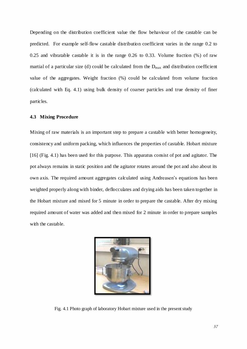
4.3 Mixing Procedure
Mixing of raw materials is an important step to prepare a castable with better homogeneity,
consistency and uniform packing, which influences the properties of castable. Hobart mixture
[16] (Fig. 4.1) has been used for this purpose. This apparatus consist of pot and agitator. The
pot always remains in static position and the agitator rotates around the pot and also about its
own axis. The required amount aggregates calculated using Andreasen’s equations has been
weighted properly along with binder, deflocculates and drying aids has been taken together in
the Hobart mixture and mixed for 5 minute in order to prepare the castable. After dry mixing
required amount of water was added and then mixed for 2 minute in order to prepare samples
with the castable.
Fig. 4.1 Photo graph of laboratory Hobart mixture used in the present study
38
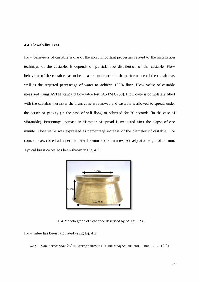
4.4 Flowability Test
Flow behaviour of castable is one of the most important properties related to the installation
technique of the castable. It depends on particle size distribution of the castable. Flow
behaviour of the castable has to be measure to determine the performance of the castable as
well as the required percentage of water to achieve 100% flow. Flow value of castable
measured using ASTM standard flow table test (ASTM C230). Flow cone is completely filled
with the castable thereafter the brass cone is removed and castable is allowed to spread under
the action of gravity (in the case of self- flow) or vibrated for 20 seconds (in the case of
vibratable). Percentage increase in diameter of spread is measured after the elapse of one
minute. Flow value was expressed as percentage increase of the diameter of castable. The
conical brass cone had inner diameter 100mm and 70mm respectively at a height of 50 mm.
Typical brass cones has been shown in Fig. 4.2.
Fig. 4.2: photo graph of flow cone described by ASTM C230
Flow value has been calculated using Eq. 4.2:
…….. (4.2)
70mm
50mm
100 mm
39
Where, 100 is the initial diameter of the cast.
4.5 Sample Preparation
4.5.1 Casting
The test samples were casted in metallic mould required size in order to test physical and
mechanical properties. As a mould lubricant, paraffin oil was used. Castable was casted in
160 40 40mm mould for the measurement of Cold Modulus of Rapture and Permanent
linear change, 65 40 40mm for Cold crushing strength, Apparent Porosity and Bulk
Density. For different testing, five samples were casted for each batch.
4.5.2 Initial setting time
Initial setting time of the low cement castable was measured by Vicat apparatus. Wet castable
was filled in the Vicat mould. In every 15 minutes needle penetration into the castable were
checked. The final setting time was determined when needle stop penetrating >30 mm above
bottom plate.
4.5.3 Drying of the castable
Low cement castable had high alumina cement as a binder that reacts with water and form
cement hydrates. That hydrates gave strength at room temperature and hydration reactions
were affected by temperature. With increase in temperature de-hydroxylation reaction should
be occurring. The rate of hydration has to be very slow due to phase transformation. If the
drying rate high there is a problem of explosion because low cement castable was so dense
and there is no space for evaporation of water. Castable requires around 24 hours for air
drying followed by oven drying at 110oC for 24 hours.
4.5.4 Firing of the castable
Castable samples were fired at 800, 1100, 1400 and 1500oC with constant firing rate 5o/min
and socking time was around 3 hours in electric arc furnace. At initial temperature chemical
bond break due to de-hydroxylation of cement hydrates. Above 1100oC, densification of
40
castable started due to the formation of ceramic bond that cause of high strength of the
castable.
4.6 Characterization
4.6.1 Apparent porosity and bulk density
Apparent porosity of the sample defined as the ratio of open pores to the bulk volume of the
material and expressed in percentage. Bulk density of the sample defined as the ratio of mass
of dry material to the bulk volume of the sample and expressed in gm/cc. Bulk density of the
sample is inversely related to the porosity of the same sample. The sample size for this
measurement was 60 40 40mm and tested by IS 1258 vacuum method. First dry weight o f
the sample taken after that put in to air tight desiccators for 30 minutes in vacuum condition.
After 30 minutes, water was introduced in the desiccators for 15 minutes. The samples were
fully enclosed with water and to fill up the pores. After that, socked and suspended weight
was taken. Calculation of apparent porosity and bulk density of the sample was calculated by
given in Eq. 4.3 and 4.4.
. . . . . . . (4.3)
. . . . . . . . . . (4.4)
4.6.2 Cold crushing strength
Cold crushing strength (CCS) is defined as the maximum amount of compressive stress per
unit area that causes fracture in the refractory material. It is measure the strength of grains as
well as strength of bonding system as expressed in Kg/cm2. Sample size of this sample was
65 65 mm and measured by ASTM C133. Hydraulic compressive testing machine
apparatus used for this measurement. Load was applied on the flat surface of the sample and
measure the load at which crack was propagating in the refractory sample. Cold crushing
strength calculated by given formula.
41
. . . . . . . . . . (4.5)
4.6.3 Cold modulus of rapture
The cold modulus of rupture of a refractory material designates the bending strength and its
suitability for use in construction of furnace lining and as expressed in Kg/cm2. This Modulus
of rapture measurement was determined by three point bending test (ASTM C233) with the
sample size was 160 40 mm and the spam length should be 100mm. During testing,
load should be uniform and applied at centre of the spam length. Using given formula cold
modulus of rapture was calculated.
. . . . . . . . . . (4.6)
Where,
W= facture load (Kg)
l= spam length
b= width of the sample
d= thickness of the sample at fracture plane
4.6.4 Permanent linear change (PLC)
Permanent linear change defined that whether sample expend or shrink after firing. This
expansion and shrinkage of the sample is occurring due to either phase transformation or
densification and it is expressed in %. Test samples for this measurement was 160 40 40
mm and fired at 1400 and 1500oC with 3 hours soaking time. In this measurement, initial
length was taken for dry sample. After that, fired the sample in elect ric arc furnace and
measure the final length of the sample. Permanent linear change was calculated by given
formula.
. . . . . . . . . . . (4.7)
Where,
42
Li = initial length of the sample (mm)
Lf = final length of the sample (mm)
4.6.5 Phase analysis
Phase analysis carried out by powder diffraction method by Rigaku, Miniflex II Japan XRD
instrument. Castable samples fired at different temperature were broken into small pieces and
ground in to fine powder by using INSMART grinding machine. Different phases present in
the fired powder sample were determined by XRD pattern. Experimental setup of X-Ray
Diffractometer has been given below:
Voltage = 35 kV
Current = 15 mA
Incident beam slit – 0.25 mm
Divergence beam slit – 0.5 mm
Radiation - Cu-Kα, λ = 1.54Å
Filter – Nickel
Scan Angle 2θ – 10-80o
Continuous Scan Speed - 0.02o per second
Analysis of obtained diffraction pattern was done by Philips X-pert high score software.
43
CHAPTER-V
RESULTS AND DISCUSSION
44
5. RESULTS AND DISCUSSION
5.1 Study the Effect of Calcined Alumina on 70% Al2O3 Low Cement Vibratable
Castable:
Bauxite based 70% Al2O3 low cement vibratable castable has been prepared with grog, brown
fused alumina, silliminte sand as the aggregates and calcium aluminium cement, micro-silica,
and calcined alumina as the additives. Particle size distribution of the aggregates for
vibratable castable follows Andreassen’s equation with q value = 0.31. This q-value has been
chosen from the earlier work [16, 34]. It has been reported that the LC castables prepared
with q value 0.31 showed high flow value with low water requirment. The study suggests that
q-value 0.31 shows good physical and mechanical properties and best for vibratable cstable.
5.1.1 Batch formulation of 70% Al2O3 low cement vibratable castable
Raw materials used in the body formulations are 86% Chinese Bauxite, Pyrophilytic Grog,
Brown fused alumina and Silliminite Sand as aggregate, calcium aluminate cement as a
binder, micro-silica and calcined alumina as a filler, dispersant and polypropylene fiber as
dry aids. Study the effect of calcined alumina on the basis of particle size and particle size
distribution on the low cement vibratable castable and study the physical and mechanical
properties. In this study, four type of calcined alumina has been used. Physical and chemical
properties of calcined alumina have been shown in Table V.I. Batch formulation of low
cement vibratable castable has been shown in Table V.II.
Table V.I Physical and chemical properties of calcined alumina
Calcined alumina Alumina-1 Alumina-2 Alumina-3 Alumina-4
Al2O3 (%) 99.0 99.5 99.0 99.0
Specific surface area (m2/gm) 2.1 3 0.8 0.23

45
Table V.II Batch formulation of low cement vibratable castable
Composition (%) T1 T2 T3 T4
Chinese Bxt. (3-5)mm 15 15 15 15
Grog (1-3)mm 18 18 18 18
Brown Fused Aalumina
(1-3)mm
12 12 12 12
Siliminite sand (0-1)mm 10 10 10 10
Brown Fused Alumina
(0-1)mm
10 10 10 10
Brown Fused Alumina
(-200#)
20 20 20 20
Calcined alumina 5 (alumina-1) 5 (alumina-2) 5 (alumina-3) 5 (alumina-4)
Cement 5 5 5 5
Micro-silica 4.8 4.8 4.8 4.8
Dispersant 0.2 0.2 0.2 0.2
PPF 0.05 0.05 0.05 0.05
5.2.2 Particle size and particle size distribution of calcined alumina
Particle size distribution of calcined alumina used in this study has been presented in Fig. 5.1.
0.1 1 10 100
0
2
4
6
80
2
4
6
80
2
4
6
80
2
4
6
8
10
Particle size micron
ALUMINA-1
Vol
ume
frac
tion
%
ALUMINA-2
ALUMINA-3
ALUMINA-4
Fig. 5.1 Particle size distribution of calcined alumina of ALUMINA-1, ALUMINA-2, ALUMINA-3
and ALUMINA-4.
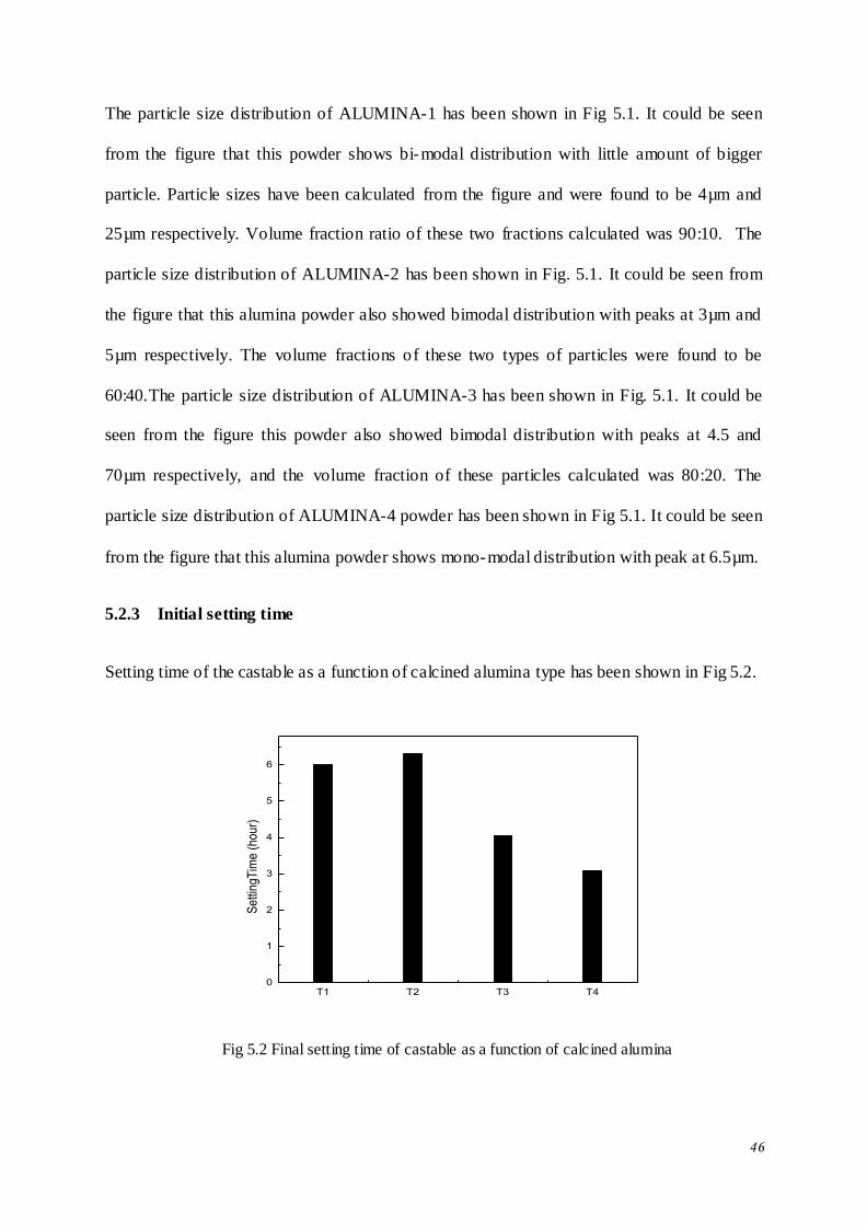
46
The particle size distribution of ALUMINA-1 has been shown in Fig 5.1. It could be seen
from the figure that this powder shows bi-modal distribution with little amount of bigger
particle. Particle sizes have been calculated from the figure and were found to be 4µm and
25µm respectively. Volume fraction ratio of these two fractions calculated was 90:10. The
particle size distribution of ALUMINA-2 has been shown in Fig. 5.1. It could be seen from
the figure that this alumina powder also showed bimodal distribution with peaks at 3µm and
5µm respectively. The volume fractions of these two types of particles were found to be
60:40.The particle size distribution of ALUMINA-3 has been shown in Fig. 5.1. It could be
seen from the figure this powder also showed bimodal distribution with peaks at 4.5 and
70µm respectively, and the volume fraction of these particles calculated was 80:20. The
particle size distribution of ALUMINA-4 powder has been shown in Fig 5.1. It could be seen
from the figure that this alumina powder shows mono-modal distribution with peak at 6.5µm.
5.2.3 Initial setting time
Setting time of the castable as a function of calcined alumina type has been shown in Fig 5.2.
T1 T2 T3 T40
1
2
3
4
5
6
Se
ttin
gT
ime
(h
ou
r)
Fig 5.2 Final setting time of castable as a function of calcined alumina
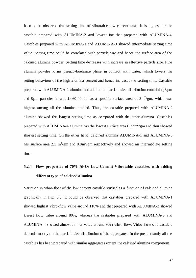
47
It could be observed that setting time of vibratable low cement castable is highest for the
castable prepared with ALUMINA-2 and lowest for that prepared with ALUMINA-4.
Castables prepared with ALUMINA-1 and ALUMINA-3 showed intermediate setting time
value. Setting time could be correlated with particle size and hence the surface area of the
calcined alumina powder. Setting time decreases with increase in effective particle size. Fine
alumina powder forms pseudo-boehmite phase in contact with water, which lowers the
setting behaviour of the high alumina cement and hence increases the setting time. Castable
prepared with ALUMINA-2 alumina had a bimodal particle size distribution containing 3µm
and 8µm particles in a ratio 60:40. It has a specific surface area of 3m2/gm, which was
highest among all the alumina studied. Thus, the castable prepared with ALUMINA-2
alumina showed the longest setting time as compared with the other alumina. Castables
prepared with ALUMINA-4 alumina has the lowest surface area 0.23m2/gm and thus showed
shortest setting time. On the other hand, calcined alumina ALUMINA-1 and ALUMINA-3
has surface area 2.1 m2/gm and 0.8m2/gm respectively and showed an intermediate setting
time.
5.2.4 Flow properties of 70% Al2O3 Low Cement Vibratable castables with adding
different type of calcined alumina
Variation in vibro-flow of the low cement castable studied as a function of calcined alumina
graphically in Fig. 5.3. It could be observed that castables prepared with ALUMINA-1
showed highest vibro-flow value around 110% and that prepared with ALUMINA-2 showed
lowest flow value around 80%, whereas the castables prepared with ALUMINA-3 and
ALUMINA-4 showed almost similar value around 90% vibro flow. Virbo-flow of a castable
depends mostly on the particle size distribution of the aggregates. In the present study all the
castables has been prepared with similar aggregates except the calcined alumina co mponent.
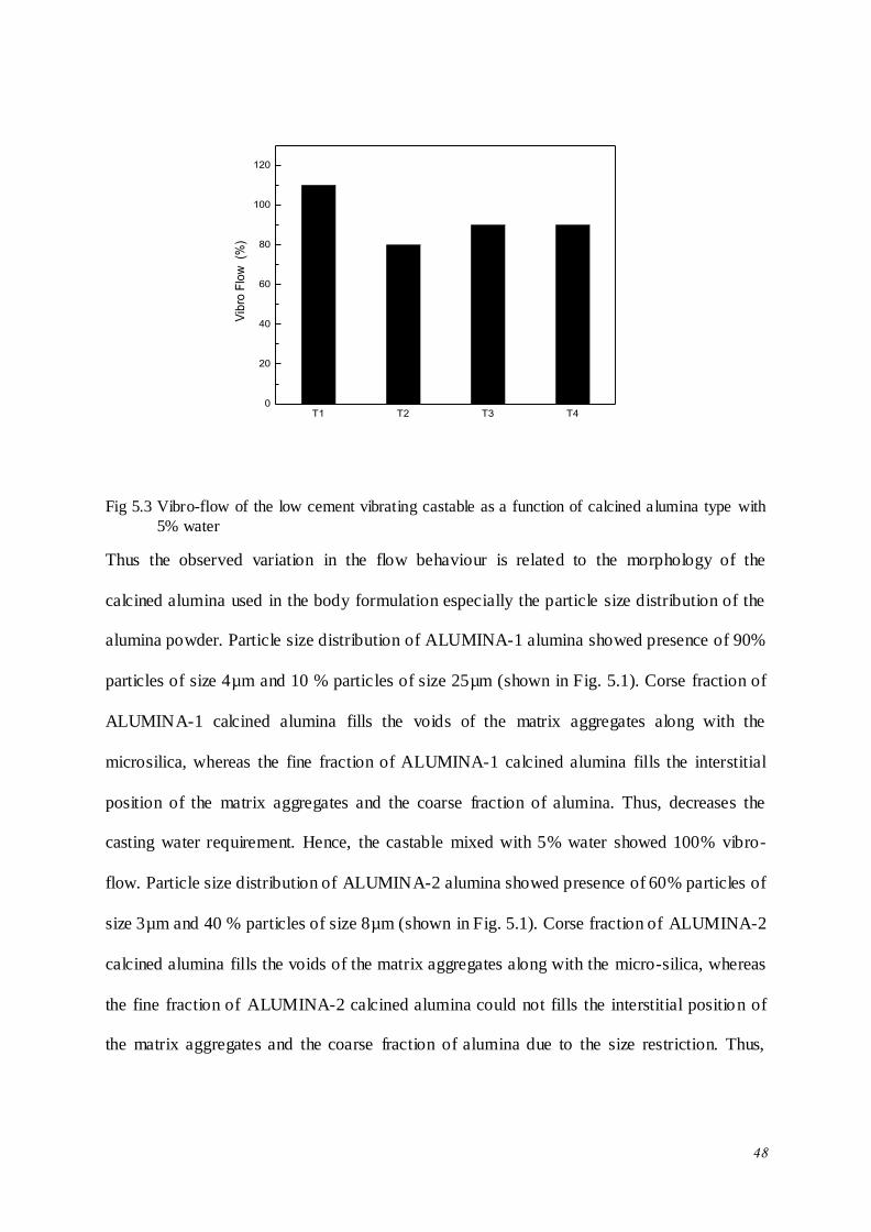
48
T1 T2 T3 T40
20
40
60
80
100
120
Vib
ro F
low
(%
)
Fig 5.3 Vibro-flow of the low cement vibrating castable as a function of calcined alumina type with
5% water
Thus the observed variation in the flow behaviour is related to the morphology of the
calcined alumina used in the body formulation especially the particle size distribution of the
alumina powder. Particle size distribution of ALUMINA-1 alumina showed presence of 90%
particles of size 4µm and 10 % particles of size 25µm (shown in Fig. 5.1). Corse fraction of
ALUMINA-1 calcined alumina fills the voids of the matrix aggregates along with the
microsilica, whereas the fine fraction of ALUMINA-1 calcined alumina fills the interstitial
position of the matrix aggregates and the coarse fraction of alumina. Thus, decreases the
casting water requirement. Hence, the castable mixed with 5% water showed 100% vibro-
flow. Particle size distribution of ALUMINA-2 alumina showed presence of 60% particles of
size 3µm and 40 % particles of size 8µm (shown in Fig. 5.1). Corse fraction of ALUMINA-2
calcined alumina fills the voids of the matrix aggregates along with the micro-silica, whereas
the fine fraction of ALUMINA-2 calcined alumina could not fills the interstitial position of
the matrix aggregates and the coarse fraction of alumina due to the size restriction. Thus,
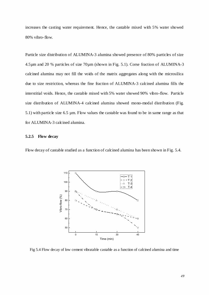
49
increases the casting water requirement. Hence, the castable mixed with 5% water showed
80% vibro-flow.
Particle size distribution of ALUMINA-3 alumina showed presence of 80% particles of size
4.5µm and 20 % particles of size 70µm (shown in Fig. 5.1). Corse fraction of ALUMINA-3
calcined alumina may not fill the voids of the matrix aggregates along with the microsilica
due to size restriction, whereas the fine fraction of ALUMINA-3 calcined alumina fills the
interstitial voids. Hence, the castable mixed with 5% water showed 90% vibro-flow. Particle
size distribution of ALUMINA-4 calcined alumina showed mono-modal distribution (Fig.
5.1) with particle size 6.5 µm. Flow values the castable was found to be in same range as that
for ALUMINA-3 calcined alumina.
5.2.5 Flow decay
Flow decay of castable studied as a function of calcined alumina has been shown in Fig. 5.4.
0 15 30 45
50
60
70
80
90
100
110
Vib
ro-f
low
(%
)
Time (min)
T 1
T 2
T-3
T-4
Fig 5.4 Flow decay of low cement vibratable castable as a function of calcined alumina and time
50
It could be seen that flow decreases with increase in time for all the castable studied. The
decrease in flow as a function of time could be correlated with the setting of the castable. It
could also be seen that flow decay does not follow any linear relationship and may be related
to the thixotropic nature of the castable. Flow decay rate of the castable has been on the basis
of initial and final flow were found 0.45, 0.45, 0.67 and 0.89 %/min for the castable prepared
with ALUMINA-1, ALUMINA-2, ALUMINA-3 and ALUMINA-4 calcined alumina
respectively. Flow decay could be correlated with setting time of castable. Setting time for
the castable prepared with ALUMINA-2 calcined alumina was 6:30 hours highest among all
the castable studied. Thus it showed lowest flow decay rate.
5.2.6 Apparent porosity (AP) and bulk density (BD)
Apparent porosity of the castable as a function of temperature and calcined alumina type has
been shown in Fig 5.5.
0 200 400 600 800 1000 1200 1400 1600
10
11
12
13
14
15
16
17
18
Ap
pa
ren
t P
oro
sity
(%
)
Temperature (oC)
T1
T2
T3
T4
Fig 5.5 Apparent porosity of low cement vibrating castable as a function of calcined alumina and
temperature
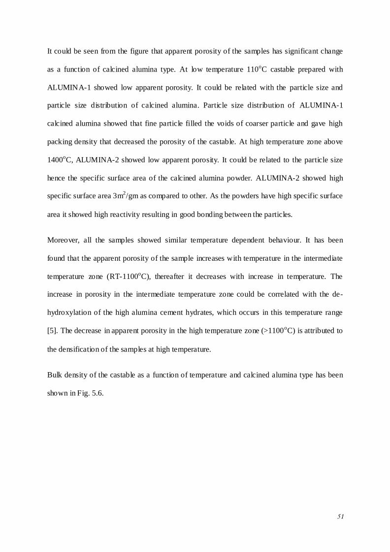
51
It could be seen from the figure that apparent porosity of the samples has significant change
as a function of calcined alumina type. At low temperature 110oC castable prepared with
ALUMINA-1 showed low apparent porosity. It could be related with the particle size and
particle size distribution of calcined alumina. Particle size distribution of ALUMINA-1
calcined alumina showed that fine particle filled the voids of coarser particle and gave high
packing density that decreased the porosity of the castable. At high temperature zone above
1400oC, ALUMINA-2 showed low apparent porosity. It could be related to the particle size
hence the specific surface area of the calcined alumina powder. ALUMINA-2 showed high
specific surface area 3m2/gm as compared to other. As the powders have high specific surface
area it showed high reactivity resulting in good bonding between the particles.
Moreover, all the samples showed similar temperature dependent behaviour. It has been
found that the apparent porosity of the sample increases with temperature in the intermediate
temperature zone (RT-1100oC), thereafter it decreases with increase in temperature. The
increase in porosity in the intermediate temperature zone could be correlated with the de-
hydroxylation of the high alumina cement hydrates, which occurs in this temperature range
[5]. The decrease in apparent porosity in the high temperature zone (>1100oC) is attributed to
the densification of the samples at high temperature.
Bulk density of the castable as a function of temperature and calcined alumina type has been
shown in Fig. 5.6.
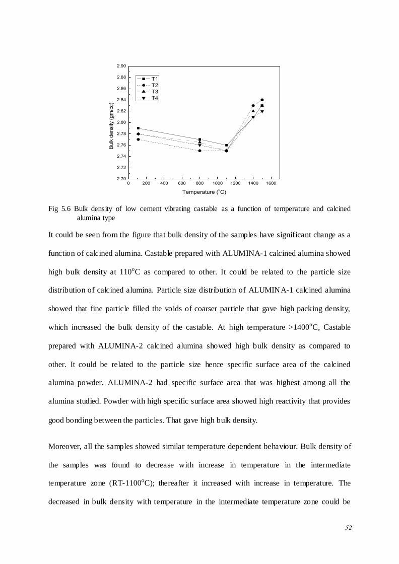
52
0 200 400 600 800 1000 1200 1400 16002.70
2.72
2.74
2.76
2.78
2.80
2.82
2.84
2.86
2.88
2.90
Bu
lk d
en
sity
(g
m/c
c)
Temperature (0C)
T1
T2
T3
T4
Fig 5.6 Bulk density of low cement vibrating castable as a function of temperature and calcined
alumina type
It could be seen from the figure that bulk density of the samples have significant change as a
function of calcined alumina. Castable prepared with ALUMINA-1 calcined alumina showed
high bulk density at 110oC as compared to other. It could be related to the particle size
distribution of calcined alumina. Particle size distribution of ALUMINA-1 calcined alumina
showed that fine particle filled the voids of coarser particle that gave high packing density,
which increased the bulk density of the castable. At high temperature >1400oC, Castable
prepared with ALUMINA-2 calcined alumina showed high bulk density as compared to
other. It could be related to the particle size hence specific surface area of the calcined
alumina powder. ALUMINA-2 had specific surface area that was highest among all the
alumina studied. Powder with high specific surface area showed high reactivity that provides
good bonding between the particles. That gave high bulk density.
Moreover, all the samples showed similar temperature dependent behaviour. Bulk density of
the samples was found to decrease with increase in temperature in the intermediate
temperature zone (RT-1100oC); thereafter it increased with increase in temperature. The
decreased in bulk density with temperature in the intermediate temperature zone could be
53
explained on the basis of de-hydroxylation of the high alumina cement hydrates, which
occurs in this temperature range [5]. The increased in bulk density in the high temperature
zone (>1100oC) is attributed to the densification of the samples at high temperature.
Temperature dependent bulk density of the sample follows an inverse relationship as that
observed for apparent porosity (Fig. 5.5) which is quite obvious.
5.2.7 Cold Crushing Strength (CCS)
Cold crushing strength of the castable as a function of temperature and calcined alumina type
has been shown in Fig 5.7. It could be seen from the figure that cold crushing strength of the
samples has significant change as a function of calcined alumina type. Castable with
ALUMINA-2 calcined alumina showed highest cold crushing strength as compared to other.
It could be related to the particle size of the calcined alumina hence specific surface area of
the calcined alumina powder. Calcined alumina powder react with water and formed pseudo-
bheomite phase that provide high strength to the castable and increased the cold crushing
strength. ALUMINA-2 calcined alumina has a high specific surface area of 3m2/gm, which
was highest among all the alumina studied. Thus castable prepared with ALUMINA-2
showed high cold crushing strength.
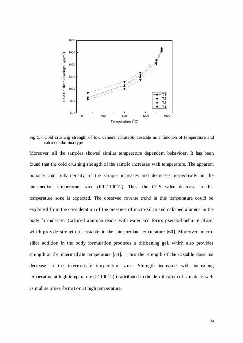
54
0 400 800 1200 1600600
800
1000
1200
1400
1600
1800
Co
ld C
rush
ing
Sty
ren
gth
(kg
/cm
2)
Temperature (0C)
T1
T2
T3
T4
Fig 5.7 Cold crushing strength of low cement vibratable castable as a function of temperature and calcined alumina type
Moreover, all the samples showed similar temperature dependent behaviour. It has been
found that the cold crushing strength of the sample increases with temperature. The apparent
porosity and bulk density of the sample increases and decreases respectively in the
intermediate temperature zone (RT-1100oC). Thus, the CCS value decrease in this
temperature zone is expected. The observed reverse trend in this temperature could be
explained from the consideration of the presence of micro-silica and calcined alumina in the
body formulation. Calcined alumina reacts with water and forms pseudo-boehmite phase,
which provide strength of castable in the intermediate temperature [60]. Moreover, micro-
silica addition in the body formulation produces a thickening gel, which also provides
strength at the intermediate temperature [34]. Thus the strength of the castable does not
decrease in the intermediate temperature zone. Strength increased with increasing
temperature at high temperature (>1100oC) is attributed to the densification of sample as well
as mullite phase formation at high temperature.

55
5.2.8 Cold Modulus of Rapture (CMOR)
Cold modulus of rapture of the castable as a function of temperature and calcined a lumina
type has been shown in Fig 5.8.
0 200 400 600 800 1000 1200 1400 1600
160
180
200
220
240
260
Co
ld M
od
ulu
s o
f ra
ptu
re (
Kg
/cm
2)
Temperature (0C)
T1
T2
T3
T4
Fig 5.8 Cold crushing strength of low cement vibratable castable as a function of temperature and
calcined alumina
It could be seen from the figure that cold modulus of rapture of the samples has significant
change as a function of calcined alumina. It could be seen from the figure that castable
prepared with ALUMINA-2 showed highest cold modulus of rapture. It could be correlated
to the particle size hence specific surface area of the calcined alumina powder. Calcined
alumina powder reacts with water and formed pseudo-beohmite phase which provide strength
of the castable.
Moreover, all the samples showed similar temperature dependent behaviour. It could be
found that cold modulus of rapture increases with increasing temperature due to presence of
micro-silica and calcined alumina. This behaviour could be explained in the same line as
described in section 5.1.7. Cold modulus of rapture increases with increase in temperature at

56
high temperature (>1100oC) is attributed to the densification of sample as well as mullite
phase formation at high temperature zone.
5.2.9 Permanent linear change (PLC)
Permanent linear change (PLC) of the castable as a function of temperature and calcined
alumina has been shown in Fig 5.9. It could be seen from the figure that the all samples had
negative permanent linear change. However, all the samples showed increase in PLC with
temperature due to densification. PLC of the samples with ALUMINA-1 shows lowest value
and sample with ALUMINA-2 shows highest. PLC depends on the pores of the sample. It
could be found that PLC may be correlated with particle size distribution of calcined alumina.
Particle size distribution of ALUMINA-1 powder shows that, fine particles of calcined
alumina powder fill the voids of coarser particle that gave high packing density and that gave
low PLC. On the other hand particle size distribution of ALUMINA-2 powder shows that
fine particles of calcined alumina powder not able to fill the voids created by coarser particle
and that gave high PLC.
T1 T2 T3 T4
0.0
-0.1
-0.2
-0.3
-0.4
-0.5
-0.6
-0.7
Pe
ram
an
en
t lin
ea
r ch
an
ge
(%
)
1400oC
1500oC
Fig5.9 Permanent Linear change of low cement vibrating castable as a function of calcined alumina at
1400OC and 1500
OC
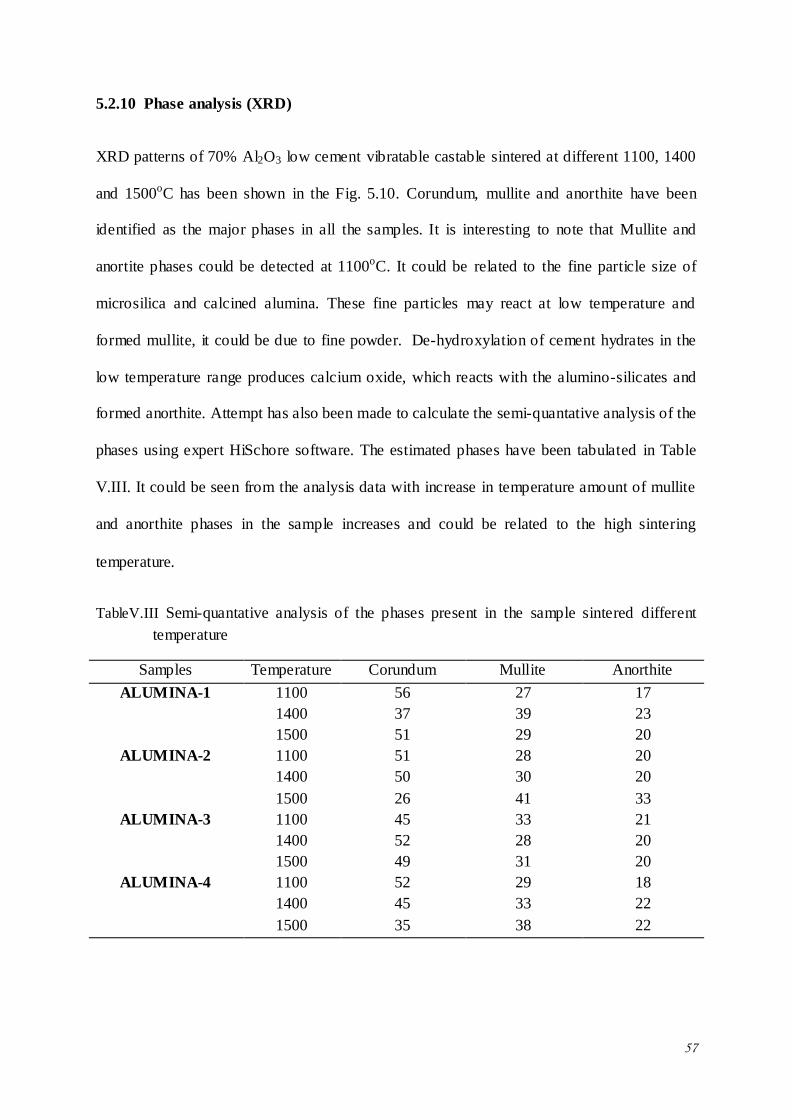
57
5.2.10 Phase analysis (XRD)
XRD patterns of 70% Al2O3 low cement vibratable castable sintered at different 1100, 1400
and 1500oC has been shown in the Fig. 5.10. Corundum, mullite and anorthite have been
identified as the major phases in all the samples. It is interesting to note that Mullite and
anortite phases could be detected at 1100oC. It could be related to the fine particle size of
microsilica and calcined alumina. These fine particles may react at low temperature and
formed mullite, it could be due to fine powder. De-hydroxylation of cement hydrates in the
low temperature range produces calcium oxide, which reacts with the alumino-silicates and
formed anorthite. Attempt has also been made to calculate the semi-quantative analysis of the
phases using expert HiSchore software. The estimated phases have been tabulated in Table
V.III. It could be seen from the analysis data with increase in temperature amount of mullite
and anorthite phases in the sample increases and could be related to the high sintering
temperature.
TableV.III Semi-quantative analysis of the phases present in the sample sintered different
temperature
Samples Temperature Corundum Mullite Anorthite
ALUMINA-1 1100 56 27 17
1400 37 39 23
1500 51 29 20
ALUMINA-2 1100 51 28 20
1400 50 30 20
1500 26 41 33
ALUMINA-3 1100 45 33 21
1400 52 28 20
1500 49 31 20
ALUMINA-4 1100 52 29 18
1400 45 33 22
1500 35 38 22
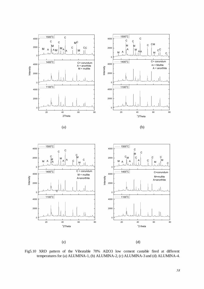
58
20 40 60 80
0
2000
4000
0
2000
4000
0
2000
4000
AA A
2Theta
1100oC
A
A = anorthiteM = mullite
M
M
MM
M
Inte
nsity
1400oC
M
C
CC
C
C
C
1500oC
C
C= corundum
20 40 60 80
0
2000
4000
0
2000
4000
0
2000
4000
AAA
o2Theta
1100oC
A
A = anorthite
M
MM
MM
Inte
nsity
1400oC
M
m = Mullite
CC
C
C
C
1500oC
C C
C
C= corundum
(a) (b)
20 40 60 80
0
2000
4000
0
2000
4000
0
2000
4000
o2Theta
1100oC
A A A A
A=anorthite
M
MM
C
Inte
nsity
1400oC
MM
M = mullite
CC
C
C
1500oC
C
C
C = corundum
20 40 60 80
0
2000
4000
0
2000
4000
0
2000
4000
A A
o2 theta
1100oC
A
A=anorthite
MM
M
M
Inte
nsity
1400oC
M
M=mullite
C
CC
C
C
C
1500oC
C
C
C=corundum
(c) (d)
Fig5.10 XRD pattern of the Vibratable 70% Al2O3 low cement castable fired at different
temperatures for (a) ALUMINA-1, (b) ALUMINA-2, (c) ALUMINA-3 and (d) ALUMINA-4.
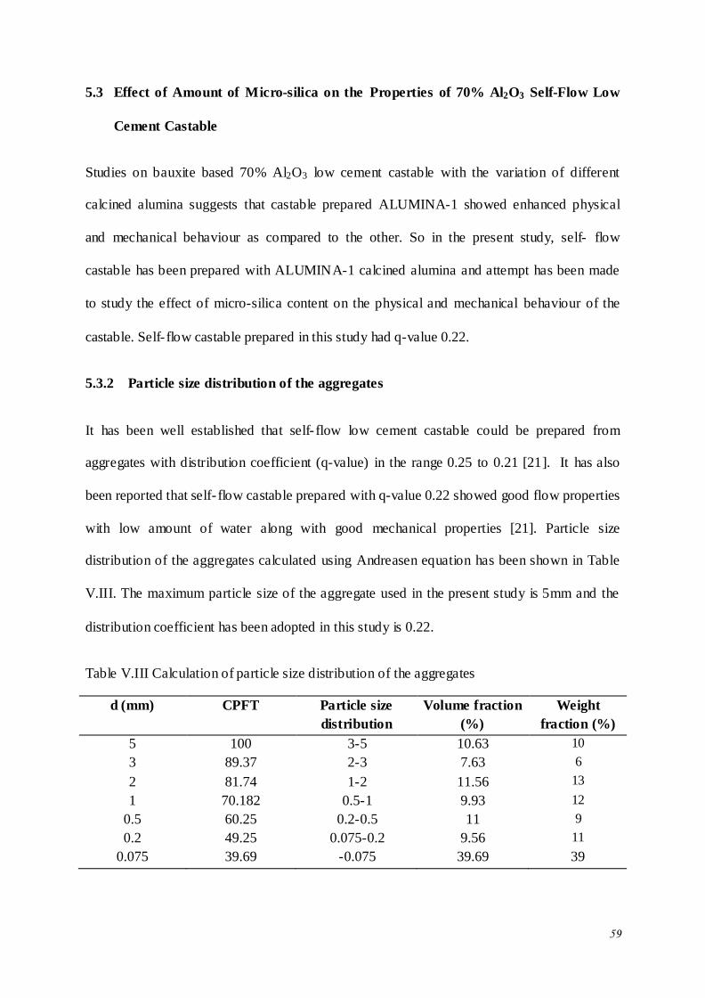
59
5.3 Effect of Amount of Micro-silica on the Properties of 70% Al2O3 Self-Flow Low
Cement Castable
Studies on bauxite based 70% Al2O3 low cement castable with the variation of different
calcined alumina suggests that castable prepared ALUMINA-1 showed enhanced physical
and mechanical behaviour as compared to the other. So in the present study, self- flow
castable has been prepared with ALUMINA-1 calcined alumina and attempt has been made
to study the effect of micro-silica content on the physical and mechanical behaviour of the
castable. Self- flow castable prepared in this study had q-value 0.22.
5.3.2 Particle size distribution of the aggregates
It has been well established that self- flow low cement castable could be prepared from
aggregates with distribution coefficient (q-value) in the range 0.25 to 0.21 [21]. It has also
been reported that self- flow castable prepared with q-value 0.22 showed good flow properties
with low amount of water along with good mechanical properties [21]. Particle size
distribution of the aggregates calculated using Andreasen equation has been shown in Table
V.III. The maximum particle size of the aggregate used in the present study is 5mm and the
distribution coefficient has been adopted in this study is 0.22.
Table V.III Calculation of particle size distribution of the aggregates
d (mm) CPFT Particle size
distribution
Volume fraction
(%)
Weight
fraction (%)
5 100 3-5 10.63 10
3 89.37 2-3 7.63 6
2 81.74 1-2 11.56 13
1 70.182 0.5-1 9.93 12
0.5 60.25 0.2-0.5 11 9
0.2 49.25 0.075-0.2 9.56 11
0.075 39.69 -0.075 39.69 39
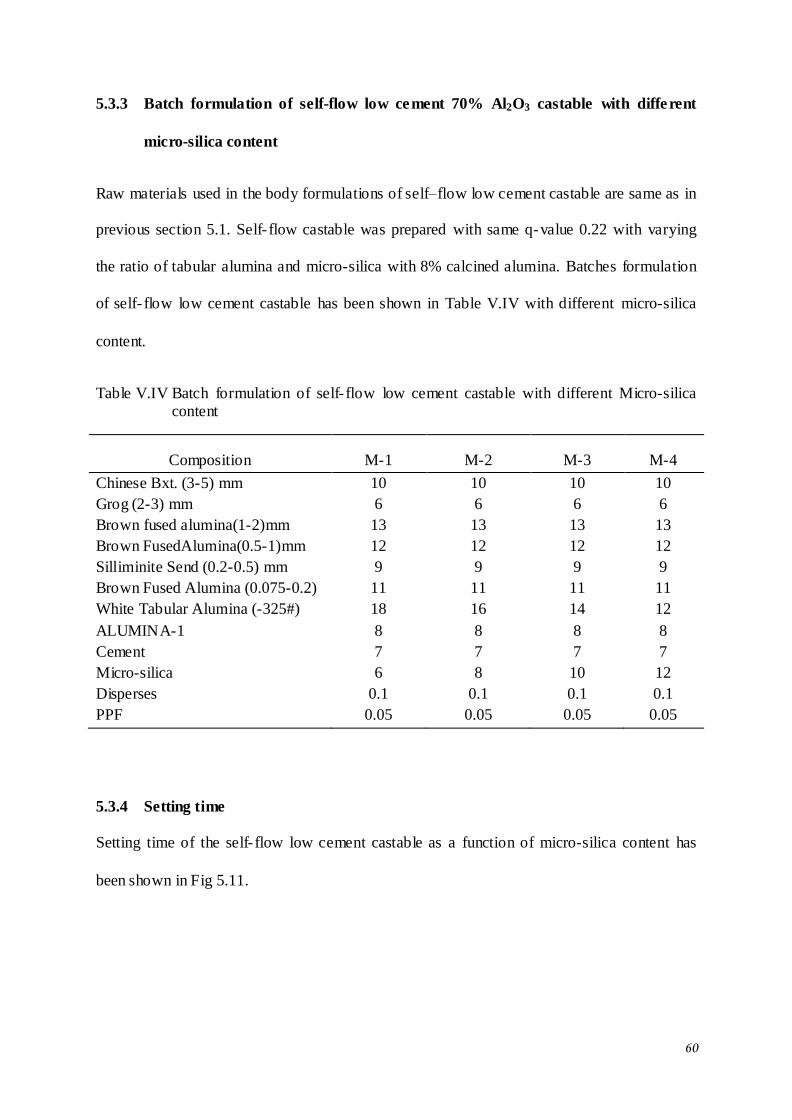
60
5.3.3 Batch formulation of self-flow low cement 70% Al2O3 castable with different
micro-silica content
Raw materials used in the body formulations of self–flow low cement castable are same as in
previous section 5.1. Self- flow castable was prepared with same q-value 0.22 with varying
the ratio of tabular alumina and micro-silica with 8% calcined alumina. Batches formulation
of self- flow low cement castable has been shown in Table V.IV with different micro-silica
content.
Table V.IV Batch formulation of self- flow low cement castable with different Micro-silica content
Composition M-1 M-2 M-3 M-4
Chinese Bxt. (3-5) mm 10 10 10 10
Grog (2-3) mm 6 6 6 6
Brown fused alumina(1-2)mm 13 13 13 13
Brown FusedAlumina(0.5-1)mm 12 12 12 12
Silliminite Send (0.2-0.5) mm 9 9 9 9
Brown Fused Alumina (0.075-0.2) 11 11 11 11
White Tabular Alumina (-325#) 18 16 14 12
ALUMINA-1 8 8 8 8
Cement 7 7 7 7
Micro-silica 6 8 10 12
Disperses 0.1 0.1 0.1 0.1
PPF 0.05 0.05 0.05 0.05
5.3.4 Setting time
Setting time of the self- flow low cement castable as a function of micro-silica content has
been shown in Fig 5.11.
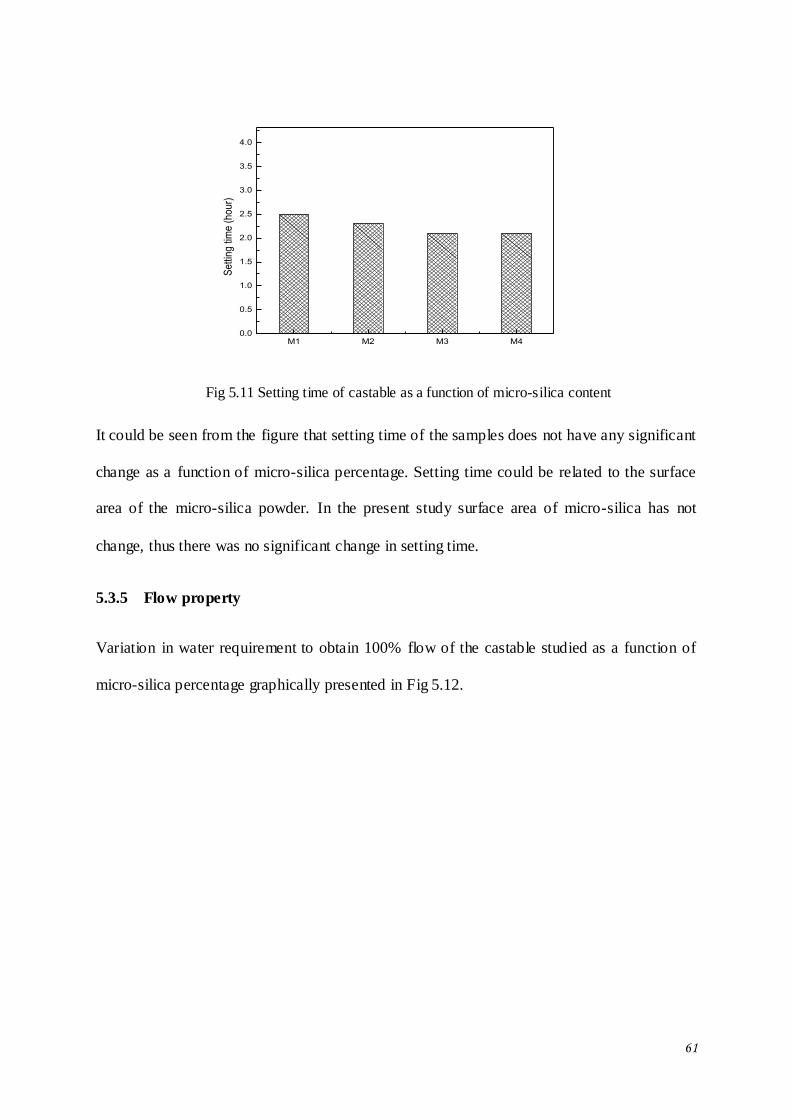
61
M1 M2 M3 M40.0
0.5
1.0
1.5
2.0
2.5
3.0
3.5
4.0
Se
ttin
g ti
me
(h
ou
r)
Fig 5.11 Setting time of castable as a function of micro-silica content
It could be seen from the figure that setting time of the samples does not have any significant
change as a function of micro-silica percentage. Setting time could be related to the surface
area of the micro-silica powder. In the present study surface area of micro-silica has not
change, thus there was no significant change in setting time.
5.3.5 Flow property
Variation in water requirement to obtain 100% flow of the castable studied as a function of
micro-silica percentage graphically presented in Fig 5.12.
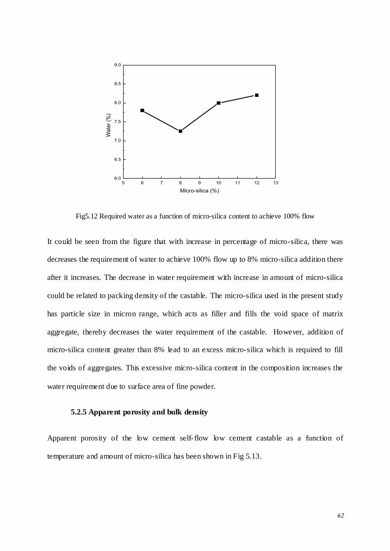
62
5 6 7 8 9 10 11 12 136.0
6.5
7.0
7.5
8.0
8.5
9.0
Wa
ter
(%)
Micro-silica (%)
Fig5.12 Required water as a function of micro-silica content to achieve 100% flow
It could be seen from the figure that with increase in percentage of micro-silica, there was
decreases the requirement of water to achieve 100% flow up to 8% micro-silica addition there
after it increases. The decrease in water requirement with increase in amount of micro-silica
could be related to packing density of the castable. The micro-silica used in the present study
has particle size in micron range, which acts as filler and fills the void space of matrix
aggregate, thereby decreases the water requirement of the castable. However, addition of
micro-silica content greater than 8% lead to an excess micro-silica which is required to fill
the voids of aggregates. This excessive micro-silica content in the composition increases the
water requirement due to surface area of fine powder.
5.2.5 Apparent porosity and bulk density
Apparent porosity of the low cement self- flow low cement castable as a function of
temperature and amount of micro-silica has been shown in Fig 5.13.
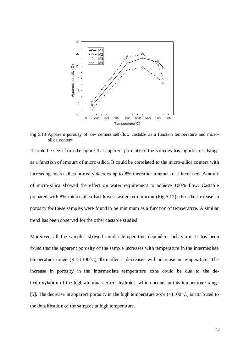
63
0 200 400 600 800 1000 1200 1400 160012
14
16
18
20
22
24
Ap
pa
ren
t p
oro
sity (
%)
Temperature(0C)
M1
M2
M3
M4
Fig 5.13 Apparent porosity of low cement self-flow castable as a function temperature and micro-
silica content
It could be seen from the figure that apparent porosity of the samples has significant change
as a function of amount of micro-silica. It could be correlated to the micro-silica content with
increasing micro silica porosity decrees up to 8% thereafter amount of it increased. Amount
of micro-silica showed the effect on water requirement to achieve 100% flow. Castable
prepared with 8% micro-silica had lowest water requirement (Fig.5.12), thus the increase in
porosity for these samples were found to be minimum as a function of temperature. A similar
trend has been observed for the other castable studied.
Moreover, all the samples showed similar temperature dependent behaviour. It has been
found that the apparent porosity of the sample increases with temperature in the intermediate
temperature range (RT-1100oC), thereafter it decreases with increase in temperature. The
increase in porosity in the intermediate temperature zone could be due to the de-
hydroxylation of the high alumina cement hydrates, which occurs in this temperature range
[5]. The decrease in apparent porosity in the high temperature zone (>1100oC) is attributed to
the densification of the samples at high temperature.
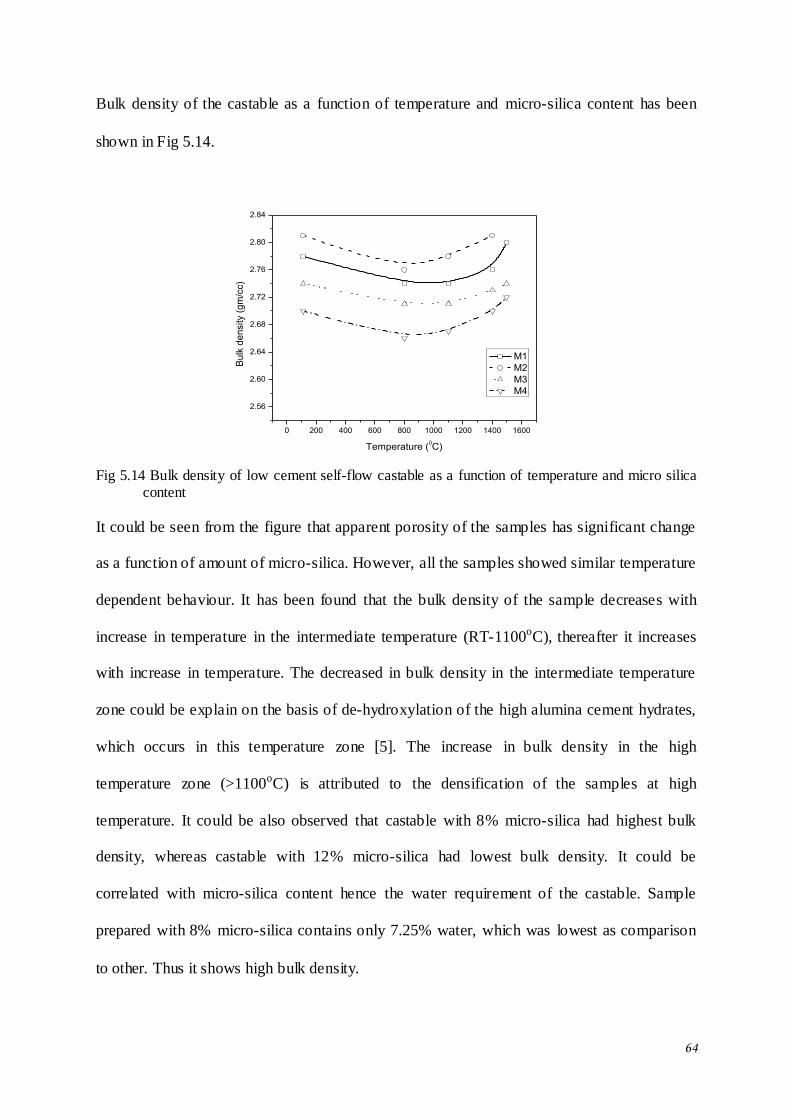
64
Bulk density of the castable as a function of temperature and micro-silica content has been
shown in Fig 5.14.
0 200 400 600 800 1000 1200 1400 1600
2.56
2.60
2.64
2.68
2.72
2.76
2.80
2.84
Bu
lk d
en
sity (
gm
/cc)
Temperature (0C)
M1
M2
M3
M4
Fig 5.14 Bulk density of low cement self-flow castable as a function of temperature and micro silica
content
It could be seen from the figure that apparent porosity of the samples has significant change
as a function of amount of micro-silica. However, all the samples showed similar temperature
dependent behaviour. It has been found that the bulk density of the sample decreases with
increase in temperature in the intermediate temperature (RT-1100oC), thereafter it increases
with increase in temperature. The decreased in bulk density in the intermediate temperature
zone could be explain on the basis of de-hydroxylation of the high alumina cement hydrates,
which occurs in this temperature zone [5]. The increase in bulk density in the high
temperature zone (>1100oC) is attributed to the densification of the samples at high
temperature. It could be also observed that castable with 8% micro-silica had highest bulk
density, whereas castable with 12% micro-silica had lowest bulk density. It could be
correlated with micro-silica content hence the water requirement of the castable. Sample
prepared with 8% micro-silica contains only 7.25% water, which was lowest as comparison
to other. Thus it shows high bulk density.
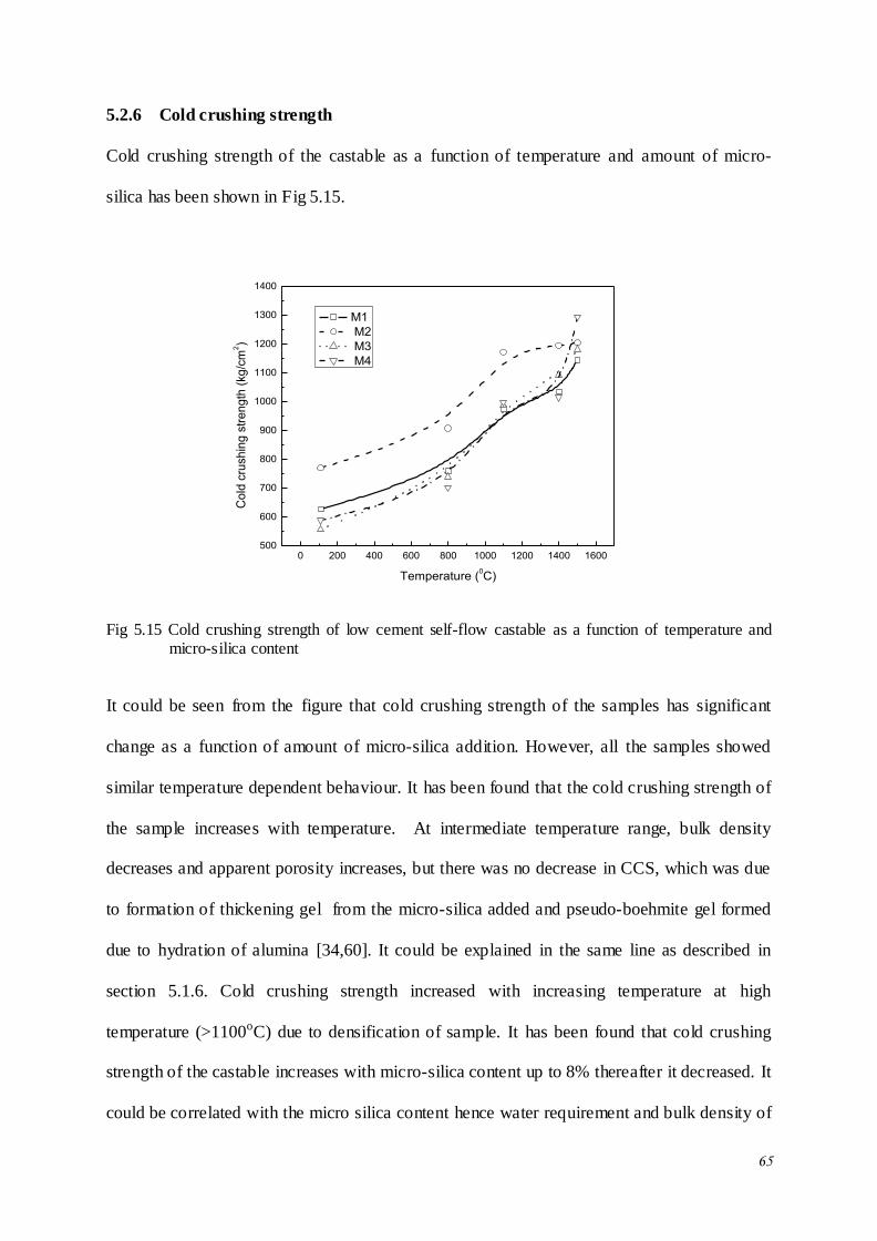
65
5.2.6 Cold crushing strength
Cold crushing strength of the castable as a function of temperature and amount of micro-
silica has been shown in Fig 5.15.
0 200 400 600 800 1000 1200 1400 1600500
600
700
800
900
1000
1100
1200
1300
1400
Co
ld c
rush
ing
str
en
gth
(kg
/cm
2)
Temperature (0C)
M1
M2
M3
M4
Fig 5.15 Cold crushing strength of low cement self-flow castable as a function of temperature and micro-silica content
It could be seen from the figure that cold crushing strength of the samples has significant
change as a function of amount of micro-silica addition. However, all the samples showed
similar temperature dependent behaviour. It has been found that the cold crushing strength of
the sample increases with temperature. At intermediate temperature range, bulk density
decreases and apparent porosity increases, but there was no decrease in CCS, which was due
to formation of thickening gel from the micro-silica added and pseudo-boehmite gel formed
due to hydration of alumina [34,60]. It could be explained in the same line as described in
section 5.1.6. Cold crushing strength increased with increasing temperature at high
temperature (>1100oC) due to densification of sample. It has been found that cold crushing
strength of the castable increases with micro-silica content up to 8% thereafter it decreased. It
could be correlated with the micro silica content hence water requirement and bulk density of
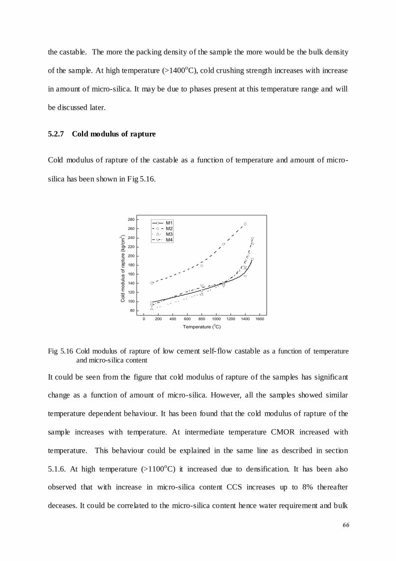
66
the castable. The more the packing density of the sample the more would be the bulk density
of the sample. At high temperature (>1400oC), cold crushing strength increases with increase
in amount of micro-silica. It may be due to phases present at this temperature range and will
be discussed later.
5.2.7 Cold modulus of rapture
Cold modulus of rapture of the castable as a function of temperature and amount of micro-
silica has been shown in Fig 5.16.
0 200 400 600 800 1000 1200 1400 1600
80
100
120
140
160
180
200
220
240
260
280
Co
ld m
od
ulu
s o
f ra
ptu
re (
kg
/cm
2)
Temperature (0C)
M1
M2
M3
M4
Fig 5.16 Cold modulus of rapture of low cement self- flow castable as a function of temperature
and micro-silica content
It could be seen from the figure that cold modulus of rapture of the samples has significant
change as a function of amount of micro-silica. However, all the samples showed similar
temperature dependent behaviour. It has been found that the cold modulus of rapture of the
sample increases with temperature. At intermediate temperature CMOR increased with
temperature. This behaviour could be explained in the same line as described in section
5.1.6. At high temperature (>1100oC) it increased due to densification. It has been also
observed that with increase in micro-silica content CCS increases up to 8% thereafter
deceases. It could be correlated to the micro-silica content hence water requirement and bulk
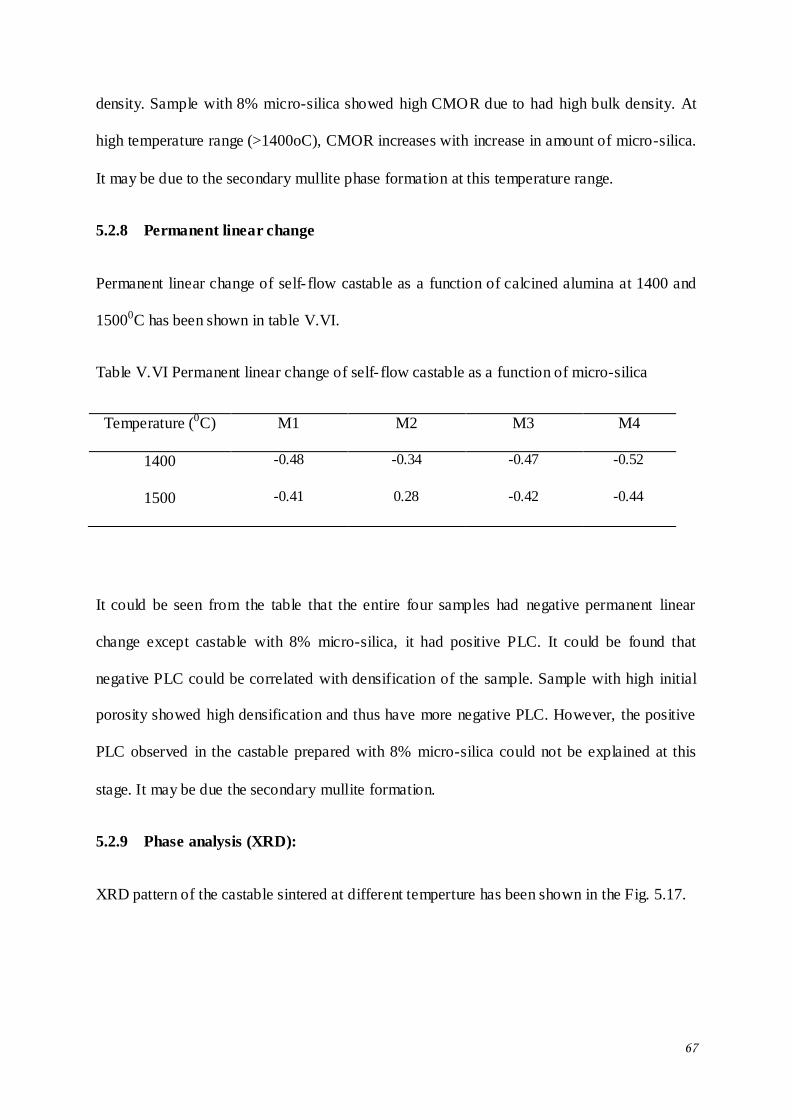
67
density. Sample with 8% micro-silica showed high CMOR due to had high bulk density. At
high temperature range (>1400oC), CMOR increases with increase in amount of micro-silica.
It may be due to the secondary mullite phase formation at this temperature range.
5.2.8 Permanent linear change
Permanent linear change of self- flow castable as a function of calcined alumina at 1400 and
15000C has been shown in table V.VI.
Table V.VI Permanent linear change of self- flow castable as a function of micro-silica
Temperature (0C) M1 M2 M3 M4
1400 -0.48 -0.34 -0.47 -0.52
1500 -0.41 0.28 -0.42 -0.44
It could be seen from the table that the entire four samples had negative permanent linear
change except castable with 8% micro-silica, it had positive PLC. It could be found that
negative PLC could be correlated with densification of the sample. Sample with high initial
porosity showed high densification and thus have more negative PLC. However, the positive
PLC observed in the castable prepared with 8% micro-silica could not be explained at this
stage. It may be due the secondary mullite formation.
5.2.9 Phase analysis (XRD):
XRD pattern of the castable sintered at different temperture has been shown in the Fig. 5.17.
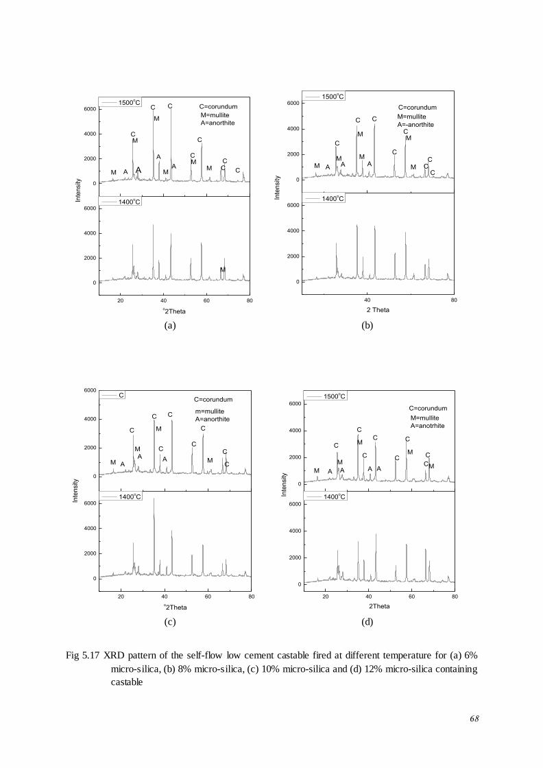
68
20 40 60 80
0
2000
4000
6000
0
2000
4000
6000
M
A
A
M
A
Inte
nsity
o2Theta
1400oC
AM M
MM
M
M=mullite
A=anorthite
CC
C
C
CC
1500oC
C
C=corundum
C
40 80
0
2000
4000
6000
0
2000
4000
6000
2 Theta
1400oC
M
MM
A MA
M=mullite
A=-anorthite
CC
C
C
C
Inte
nsity
1500oC
C
C C
C=corundum
MMA
(a) (b)
20 40 60 80
0
2000
4000
6000
0
2000
4000
6000
AA
C
M
M
o2Theta
1400oC
M
M
A
m=mullite
A=anorthite
C
C
C
C
Inte
nsity
C
C
C C
C=corundum
20 40 60 80
0
2000
4000
6000
0
2000
4000
6000
AAAM
MC
M
M
2Theta
1400oC
M A
M=mullite
A=anotrhite
C
C
C
C
C
Inte
nsity
1500oC
C
C
C=corundum
(c) (d)
Fig 5.17 XRD pattern of the self-flow low cement castable fired at different temperature for (a) 6%
micro-silica, (b) 8% micro-silica, (c) 10% micro-silica and (d) 12% micro-silica containing
castable

69
Analysis of XRD patterns revealed the presence of corundum, mullite and anorthite as the
major phase in the samples. Semi-quantitative analysis of the different phases as a function of
micro-silica content has been presented in Table V.VII. It could be seen that with increase in
sintering temperature as well as micro-silica content in the formulation mullite phase in the
sample increases and could be related to the increases micro-silica content in the formulation.
Cold crushing strength and cold modulus of rapture could be correlated with mullite
formation. it could be seen by semi-quantative analysis of the sample, with increase the
amount of micro-silica, mullite phase increased at 1500oC, thus increased the strength of the
castable with increase in micro-silica content.
Table V.VII Semi-quantitative analysis of the phases present in the sample sintered different
temperature
Sample Temperature Corundum Mullite Anorthite
M1 1400 59 18 23
1500 50 29 21
M2 1400 42 35 22
1500 43 25 33
M3 1400 63 19 18
1500 55 26 19
M4 1400 50 22 28
1500 21 34 45
5.4 Effect of Amount of Calcined Alumina in 70% Al2O3 self-flow low cement castable
Studies on bauxite based 70% Al2O3 low cement castable with the variation of different
amount of micro-silica suggests that castable prepared 8% micro-silica showed enhanced
physical and mechanical behaviour as compared to the other. So in the present study, self-
flow castable has been prepared with 8% micro-silica and attempt has been made to study the
effect of calcined alumina (ALUMINA-1) content on the physical and mechanical behaviour
of the castable. Self- flow castable prepared in this study had also q-value 0.22.
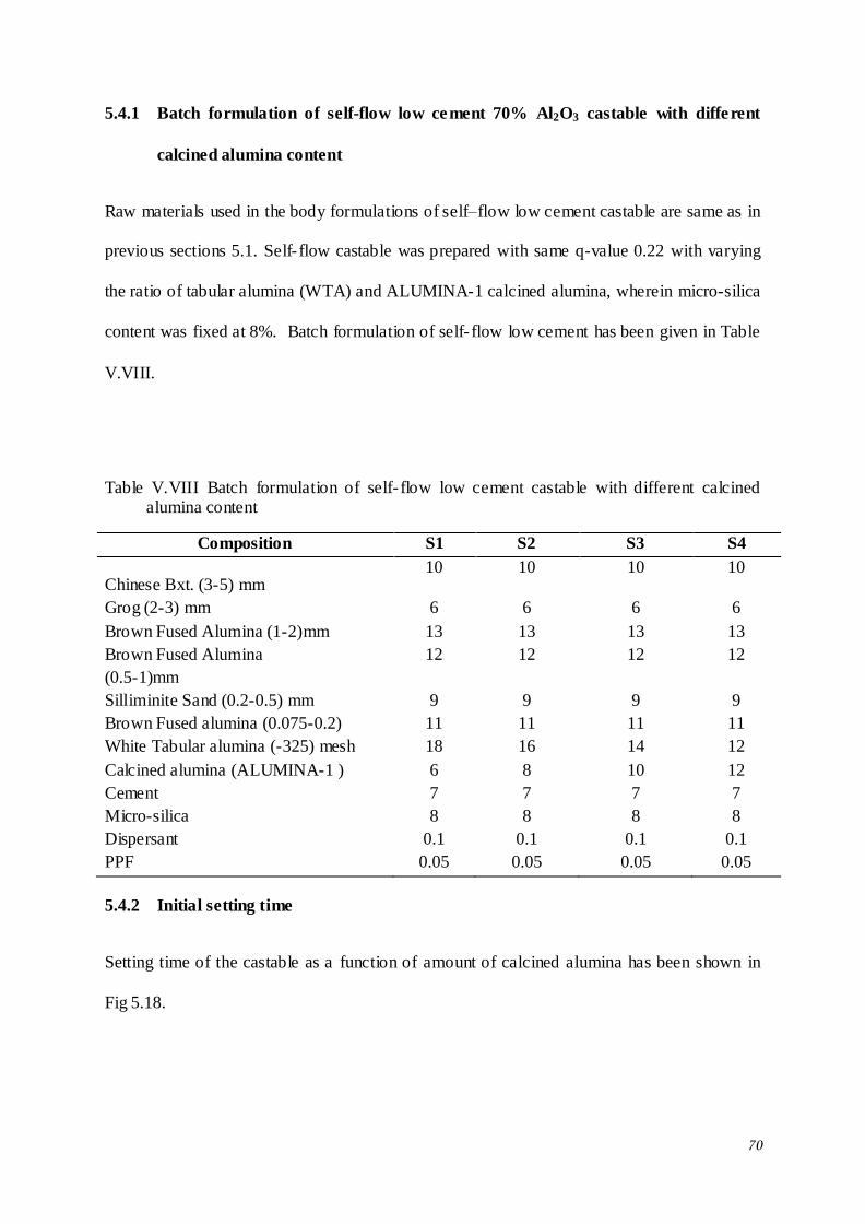
70
5.4.1 Batch formulation of self-flow low cement 70% Al2O3 castable with different
calcined alumina content
Raw materials used in the body formulations of self–flow low cement castable are same as in
previous sections 5.1. Self- flow castable was prepared with same q-value 0.22 with varying
the ratio of tabular alumina (WTA) and ALUMINA-1 calcined alumina, wherein micro-silica
content was fixed at 8%. Batch formulation of self- flow low cement has been given in Table
V.VIII.
Table V.VIII Batch formulation of self- flow low cement castable with different calcined alumina content
Composition S1 S2 S3 S4
Chinese Bxt. (3-5) mm 10 10 10 10
Grog (2-3) mm 6 6 6 6
Brown Fused Alumina (1-2)mm 13 13 13 13
Brown Fused Alumina
(0.5-1)mm
12 12 12 12
Silliminite Sand (0.2-0.5) mm 9 9 9 9
Brown Fused alumina (0.075-0.2) 11 11 11 11
White Tabular alumina (-325) mesh 18 16 14 12
Calcined alumina (ALUMINA-1 ) 6 8 10 12
Cement 7 7 7 7
Micro-silica 8 8 8 8
Dispersant 0.1 0.1 0.1 0.1
PPF 0.05 0.05 0.05 0.05
5.4.2 Initial setting time
Setting time of the castable as a function of amount of calcined alumina has been shown in
Fig 5.18.
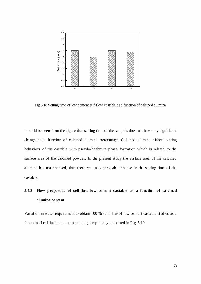
71
S1 S2 S3 S40.0
0.5
1.0
1.5
2.0
2.5
3.0
3.5
4.0
4.5
Se
ttin
g tim
e (
ho
ur)
Fig 5.18 Setting time of low cement self-flow castable as a function of calcined alumina
It could be seen from the figure that setting time of the samples does not have any significant
change as a function of calcined alumina percentage. Calcined alumina affects setting
behaviour of the castable with pseudo-boehmite phase formation which is related to the
surface area of the calcined powder. In the present study the surface area of the calcined
alumina has not changed, thus there was no appreciable change in the setting time of the
castable.
5.4.3 Flow properties of self-flow low cement castable as a function of calcined
alumina content
Variation in water requirement to obtain 100 % self- flow of low cement castable studied as a
function of calcined alumina percentage graphically presented in Fig. 5.19.
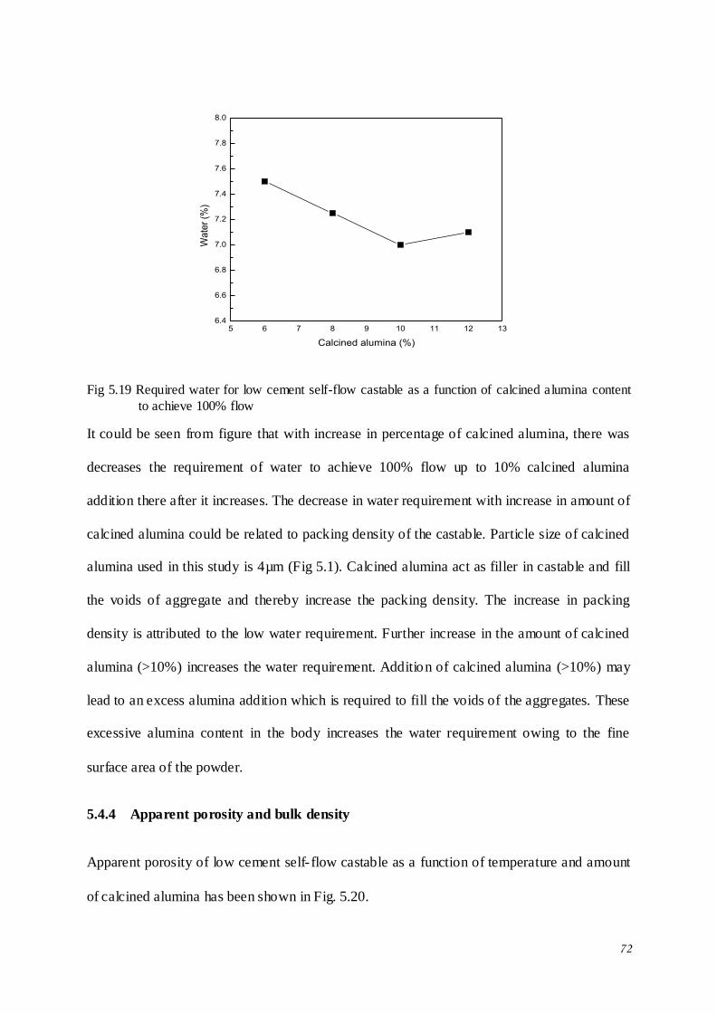
72
5 6 7 8 9 10 11 12 136.4
6.6
6.8
7.0
7.2
7.4
7.6
7.8
8.0
Wa
ter
(%)
Calcined alumina (%)
Fig 5.19 Required water for low cement self-flow castable as a function of calcined alumina content
to achieve 100% flow
It could be seen from figure that with increase in percentage of calcined alumina, there was
decreases the requirement of water to achieve 100% flow up to 10% calcined alumina
addition there after it increases. The decrease in water requirement with increase in amount of
calcined alumina could be related to packing density of the castable. Particle size of calcined
alumina used in this study is 4µm (Fig 5.1). Calcined alumina act as filler in castable and fill
the voids of aggregate and thereby increase the packing density. The increase in packing
density is attributed to the low water requirement. Further increase in the amount of calcined
alumina (>10%) increases the water requirement. Addition of calcined alumina (>10%) may
lead to an excess alumina addition which is required to fill the voids of the aggregates. These
excessive alumina content in the body increases the water requirement owing to the fine
surface area of the powder.
5.4.4 Apparent porosity and bulk density
Apparent porosity of low cement self- flow castable as a function of temperature and amount
of calcined alumina has been shown in Fig. 5.20.
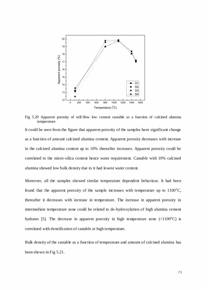
73
0 200 400 600 800 1000 1200 1400 160012
13
14
15
16
17
18
19
20
Ap
pa
ren
t p
oro
sity (
%)
Temperature (0C)
S1
S2
S3
S4
Fig 5.20 Apparent porosity of self-flow low cement castable as a function of calcined alumina
temperature
It could be seen from the figure that apparent porosity of the samples have significant change
as a function of amount calcined alumina content. Apparent porosity decreases with increase
in the calcined alumina content up to 10% thereafter increases. Apparent porosity could be
correlated to the micro-silica content hence water requirement. Castable with 10% calcined
alumina showed low bulk density due to it had lowest water content.
Moreover, all the samples showed similar temperature dependent behaviour. It had been
found that the apparent porosity of the sample increases with temperature up to 1100oC,
thereafter it decreases with increase in temperature. The increase in apparent porosity in
intermediate temperature zone could be related to de-hydroxylation of high alumina cement
hydrates [5]. The decrease in apparent porosity in high temperature zone (>1100oC) is
correlated with densification of castable at high temperature.
Bulk density of the castable as a function of temperature and amount of calcined alumina has
been shown in Fig 5.21.
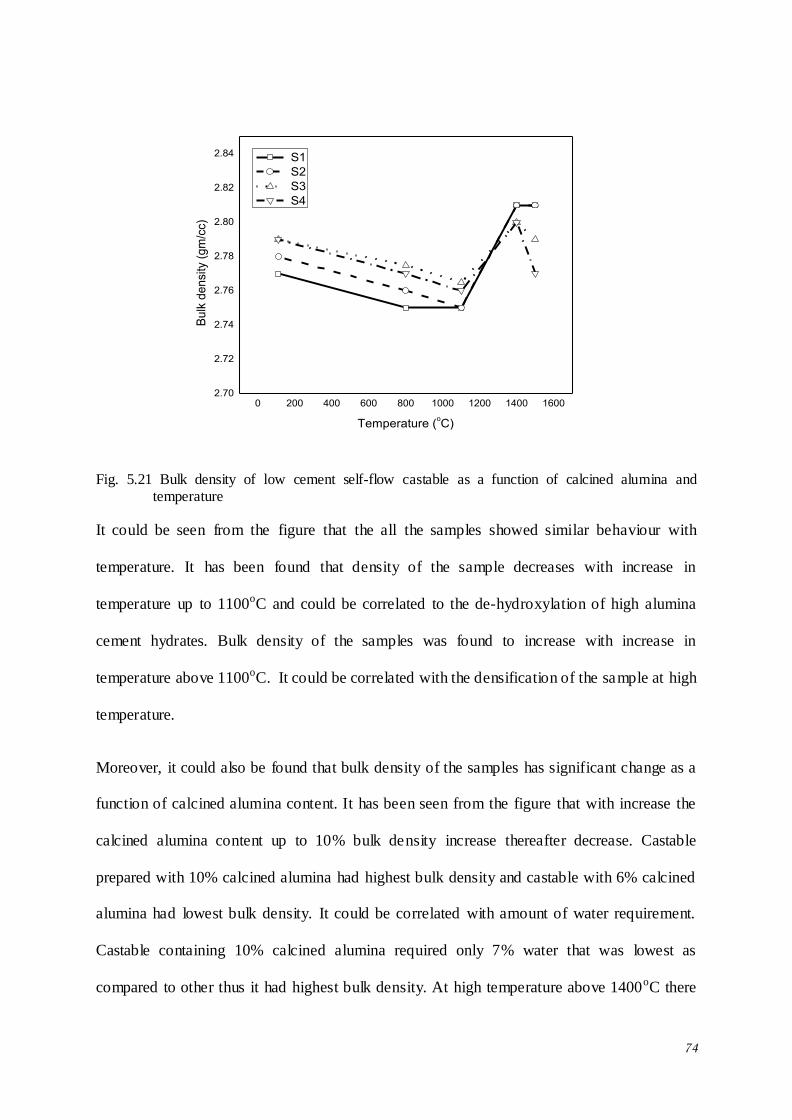
74
0 200 400 600 800 1000 1200 1400 16002.70
2.72
2.74
2.76
2.78
2.80
2.82
2.84
Bu
lk d
en
sity (
gm
/cc)
Temperature (oC)
S1
S2
S3
S4
Fig. 5.21 Bulk density of low cement self-flow castable as a function of calcined alumina and temperature
It could be seen from the figure that the all the samples showed similar behaviour with
temperature. It has been found that density of the sample decreases with increase in
temperature up to 1100oC and could be correlated to the de-hydroxylation of high alumina
cement hydrates. Bulk density of the samples was found to increase with increase in
temperature above 1100oC. It could be correlated with the densification of the sample at high
temperature.
Moreover, it could also be found that bulk density of the samples has significant change as a
function of calcined alumina content. It has been seen from the figure that with increase the
calcined alumina content up to 10% bulk density increase thereafter decrease. Castable
prepared with 10% calcined alumina had highest bulk density and castable with 6% calcined
alumina had lowest bulk density. It could be correlated with amount of water requirement.
Castable containing 10% calcined alumina required only 7% water that was lowest as
compared to other thus it had highest bulk density. At high temperature above 1400oC there
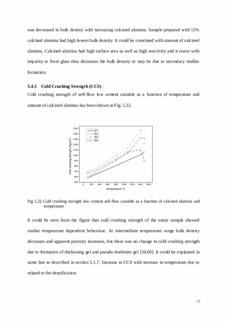
75
was decreased in bulk density with increasing calcined alumina. Sample prepared with 12%
calcined alumina had high lowest bulk density. It could be correlated with amount of calcined
alumina. Calcined alumina had high surface area as well as high reactivity and it reacts with
impurity to form glass thus decreases the bulk density or may be due to secondary mullite
formation.
5.4.5 Cold Crushing Strength (CCS)
Cold crushing strength of self- flow low cement castable as a function of temperature and
amount of calcined alumina has been shown in Fig. 5.22.
0 200 400 600 800 1000 1200 1400 1600500
600
700
800
900
1000
1100
1200
1300
1400
1500
Co
ld c
rush
ing
str
en
gth
(K
g/c
m2)
temperature oC
S1
S2
S3
S4
Fig 5.22 Cold crushing strength low cement self-flow castable as a function of calcined alumina and temperature
It could be seen from the figure that cold crushing strength of the entire sample showed
similar temperature dependent behaviour. At intermediate temperature range bulk density
decreases and apparent porosity increases, but there was no change in cold crushing strength
due to formation of thickening gel and pseudo-boehmite gel [34,60]. It could be explained in
same line as described in section 5.1.7. Increase in CCS with increase in temperature due to
related to the densification.
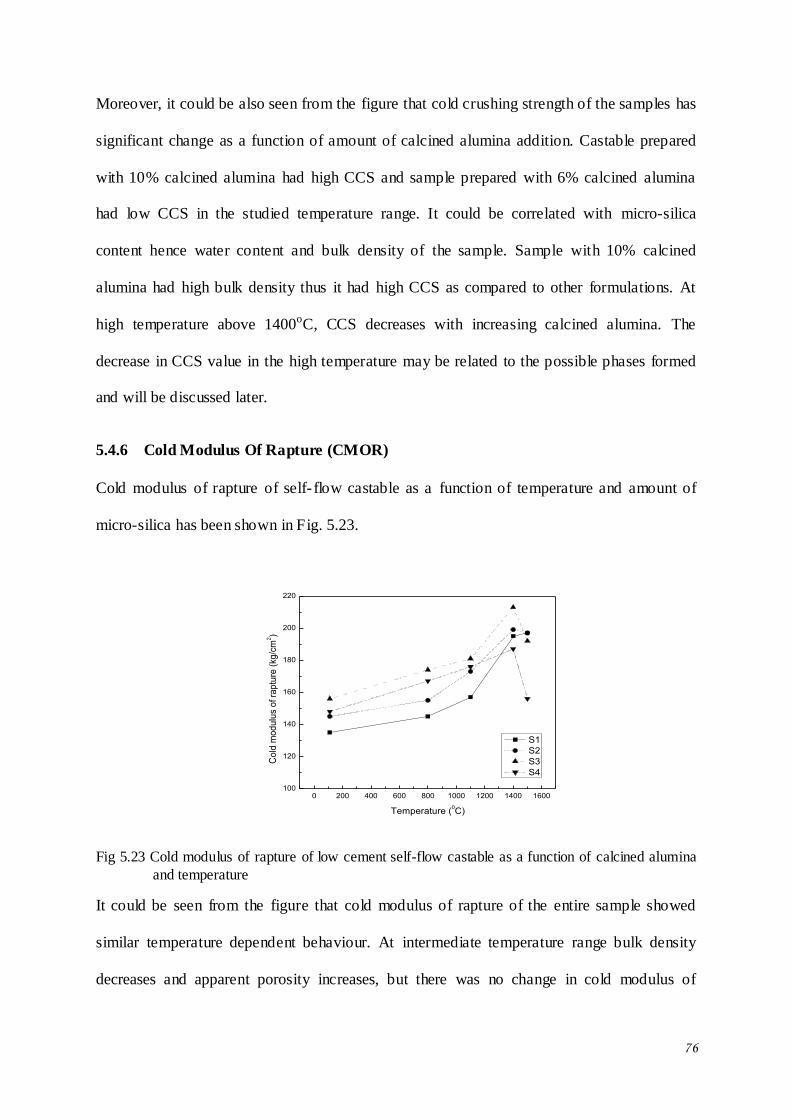
76
Moreover, it could be also seen from the figure that cold crushing strength of the samples has
significant change as a function of amount of calcined alumina addition. Castable prepared
with 10% calcined alumina had high CCS and sample prepared with 6% calcined alumina
had low CCS in the studied temperature range. It could be correlated with micro-silica
content hence water content and bulk density of the sample. Sample with 10% calcined
alumina had high bulk density thus it had high CCS as compared to other formulations. At
high temperature above 1400oC, CCS decreases with increasing calcined alumina. The
decrease in CCS value in the high temperature may be related to the possible phases formed
and will be discussed later.
5.4.6 Cold Modulus Of Rapture (CMOR)
Cold modulus of rapture of self- flow castable as a function of temperature and amount of
micro-silica has been shown in Fig. 5.23.
0 200 400 600 800 1000 1200 1400 1600100
120
140
160
180
200
220
Co
ld m
od
ulu
s o
f ra
ptu
re (
kg/c
m2)
Temperature (0C)
S1
S2
S3
S4
Fig 5.23 Cold modulus of rapture of low cement self-flow castable as a function of calcined alumina
and temperature
It could be seen from the figure that cold modulus of rapture of the entire sample showed
similar temperature dependent behaviour. At intermediate temperature range bulk density
decreases and apparent porosity increases, but there was no change in cold modulus of
77
rapture, which was due to formation of pseudo-beohmite and thickening gel [34,60]. It could
be explained same line as described in section 5.1.7. CMOR increased with increase in
temperature above 1100oC due to densification and may be explained from the phases present
in the sample.
Moreover, it could be also seen from the figure that cold modulus of rapture of the samples
has significant change as a function of amount of calcined alumina addition. Below 1400oC,
castable prepared with 10% calcined alumina had high CMOR and sample prepared with 6%
calcined alumina had low CMOR. It could be correlated with bulk density of the castable.
Sample with high 10% calcined alumina had high bulk density (Fig 5.21), thus it had high
CMOR. Above 1400oC, CMOR decreased with increase in calcined alumina addition in the
body formulation. It could be related to the phases formed in the castab le matrix and has been
discussed later.
5.4.7 Permanent linear change (PLC)
Permanent linear change of self- flow castable as a function of calcined alumina at 1400 and
15000C has been shown in table V.IX.
Table V.IX Permanent linear change of self- flow castable as a function of calcined alumina
Temperature (oC) S1 S2 S3 S4
1400 -0.45 -0.34 -0.29 -0.32
1500 0.21 0.28 0.30 0.57
It could be seen from the Table that at 1400oC, all the samples showed negative permanent
linear change. Castable prepared with 10% calcined alumina had low PLC and castable
prepared with 6% calcined alumina had high PLC. It could be correlated with bulk density of
the castable at low temperature. Sample with 10% calcined alumina had high bulk density
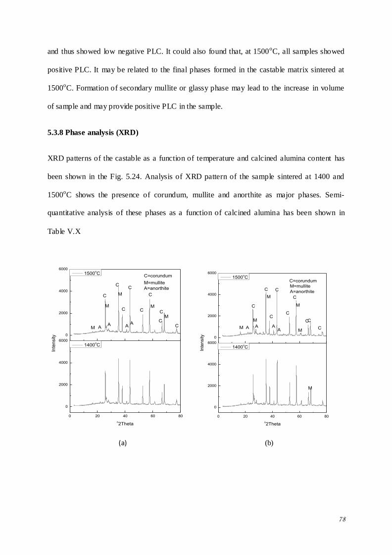
78
and thus showed low negative PLC. It could also found that, at 1500oC, all samples showed
positive PLC. It may be related to the final phases formed in the castable matrix sintered at
1500oC. Formation of secondary mullite or glassy phase may lead to the increase in volume
of sample and may provide positive PLC in the sample.
5.3.8 Phase analysis (XRD)
XRD patterns of the castable as a function of temperature and calcined alumina content has
been shown in the Fig. 5.24. Analysis of XRD pattern of the sample sintered at 1400 and
1500oC shows the presence of corundum, mullite and anorthite as major phases. Semi-
quantitative analysis of these phases as a function of calcined alumina has been shown in
Table V.X
0 20 40 60 80
0
2000
4000
6000
0
2000
4000
6000
M
M
A
M
M
o2Theta
1400oC
M AA
A
M=mullite
A=anorthite
C
C
C
C
CC
Inte
nsi
ty
1500oC
C
C=corundum
C C
0 20 40 60 80
0
2000
4000
6000
0
2000
4000
6000
o2Theta
1400oC
M A
M
M
M
M
AA
AM
M=mullite
A=anorthiteCC
Inte
nsi
ty
1500oC
C
C
CC
C
CC
C=corundum
(a) (b)
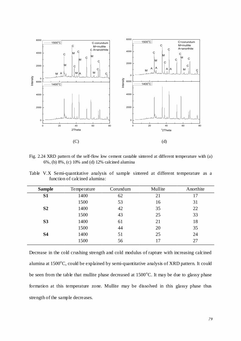
79
0 20 40 60 80
0
2000
4000
6000
0
2000
4000
6000
A M
M
M
M
M
2Theta
1400oC
M A
M=mullite
A=anotrhite
C
C
C
C
C
C
C
C
Inte
nsi
ty
1500oC
C
C-corundum
M
0 20 40 60 80
0
2000
4000
6000
0
2000
4000
6000
M
M
A
M
M
o2Theta
1400oC
M
A A A
M=mullite
A=anorthite
C
C
C
C
C
C
C
C
Inte
nsi
ty
1500oC
C
C=corundum
(C) (d)
Fig. 2.24 XRD pattern of the self-flow low cement castable sintered at different temperature with (a)
6%, (b) 8%, (c) 10% and (d) 12% calcined alumina
Table V.X Semi-quantitative analysis of sample sintered at different temperature as a function of calcined alumina:
Sample Temperature Corundum Mullite Anorthite
S1 1400 62 21 17
1500 53 16 31
S2 1400 42 35 22
1500 43 25 33
S3 1400 61 21 18
1500 44 20 35
S4 1400 51 25 24
1500 56 17 27
Decrease in the cold crushing strength and cold modulus of rapture with increasing calcined
alumina at 1500oC, could be explained by semi-quantitative analysis of XRD pattern. It could
be seen from the table that mullite phase decreased at 1500oC. It may be due to glassy phase
formation at this temperature zone. Mullite may be dissolved in this glassy phase thus
strength of the sample decreases.
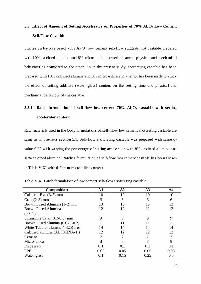
80
5.5 Effect of Amount of Setting Accelerator on Properties of 70% Al2O3 Low Cement
Self-Flow Castable
Studies on bauxite based 70% Al2O3 low cement self- flow suggests that castable prepared
with 10% calcined alumina and 8% micro-silica showed enhanced physical and mechanical
behaviour as compared to the other. So in the present study, shotcreting castable has been
prepared with 10% calcined alumina and 8% micro-silica and attempt has been made to study
the effect of setting additive (water glass) content on the setting time and physical and
mechanical behaviour of the castable.
5.5.1 Batch formulation of self-flow low cement 70% Al2O3 castable with setting
accelerator content
Raw materials used in the body formulations of self–flow low cement shotcreting castable are
same as in previous section 5.1. Self- flow shotcreting castable was prepared with same q-
value 0.22 with varying the percentage of setting accelerator with 8% calcined alumina and
10% calcined alumina. Batches formulation of self- flow low cement castable has been shown
in Table V.XI with different micro-silica content.
Table V.XI Batch formulation of low cement self- flow shotcreting castable
Composition A1 A2 A3 A4
Calcined Bxt. (3-5) mm 10 10 10 10
Grog (2-3) mm 6 6 6 6 Brown Fused Alumina (1-2)mm 13 13 13 13 Brown Fused Alumina
(0.5-1)mm
12 12 12 12
Silliminite Sand (0.2-0.5) mm 9 9 9 9
Brown Fused alumina (0.075-0.2) 11 11 11 11 White Tabular alumina (-325) mesh 14 14 14 14 Calcined alumina (ALUMINA-1 ) 12 12 12 12
Cement 7 7 7 7 Micro-silica 8 8 8 8
Dispersant 0.1 0.1 0.1 0.1 PPF 0.05 0.05 0.05 0.05 Water glass 0.1 0.15 0.25 0.5
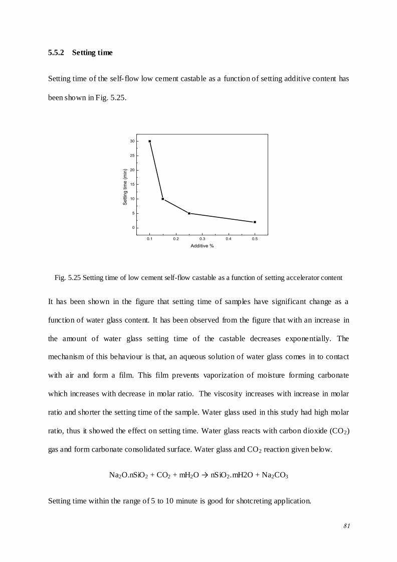
81
5.5.2 Setting time
Setting time of the self- flow low cement castable as a function of setting additive content has
been shown in Fig. 5.25.
0.1 0.2 0.3 0.4 0.5
0
5
10
15
20
25
30
Se
ttin
g tim
e (
min
)
Additive %
Fig. 5.25 Setting time of low cement self-flow castable as a function of setting accelerator content
It has been shown in the figure that setting time of samples have significant change as a
function of water glass content. It has been observed from the figure that with an increase in
the amount of water glass setting time of the castable decreases exponentially. The
mechanism of this behaviour is that, an aqueous solution of water glass comes in to contact
with air and form a film. This film prevents vaporization of moisture forming carbonate
which increases with decrease in molar ratio. The viscosity increases with increase in molar
ratio and shorter the setting time of the sample. Water glass used in this study had high molar
ratio, thus it showed the effect on setting time. Water glass reacts with carbon dioxide (CO2)
gas and form carbonate consolidated surface. Water glass and CO2 reaction given below.
Na2O.nSiO2 + CO2 + mH2O → nSiO2.mH2O + Na2CO3
Setting time within the range of 5 to 10 minute is good for shotcreting application.
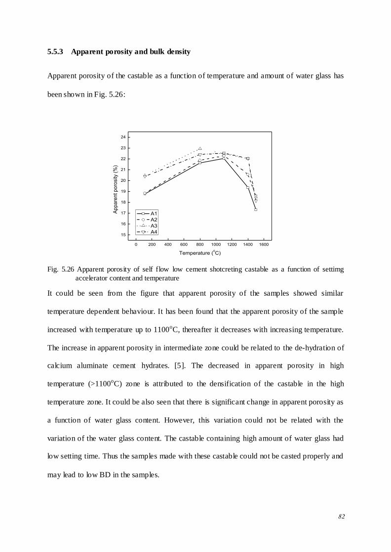
82
5.5.3 Apparent porosity and bulk density
Apparent porosity of the castable as a function of temperature and amount of water glass has
been shown in Fig. 5.26:
0 200 400 600 800 1000 1200 1400 1600
15
16
17
18
19
20
21
22
23
24
Ap
pa
ren
t p
oro
sity
(%
)
Temperature (0C)
A1
A2
A3
A4
Fig. 5.26 Apparent porosity of self flow low cement shotcreting castable as a function of settimg
accelerator content and temperature
It could be seen from the figure that apparent porosity of the samples showed similar
temperature dependent behaviour. It has been found that the apparent porosity of the sample
increased with temperature up to 1100oC, thereafter it decreases with increasing temperature.
The increase in apparent porosity in intermediate zone could be related to the de-hydration of
calcium aluminate cement hydrates. [5]. The decreased in apparent porosity in high
temperature (>1100oC) zone is attributed to the densification of the castable in the high
temperature zone. It could be also seen that there is significant change in apparent porosity as
a function of water glass content. However, this variation could not be related with the
variation of the water glass content. The castable containing high amount of water glass had
low setting time. Thus the samples made with these castable could not be casted properly and
may lead to low BD in the samples.
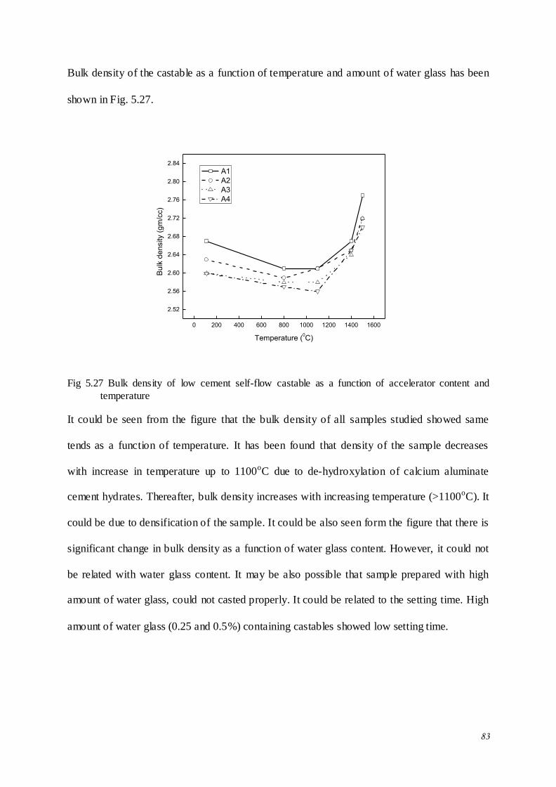
83
Bulk density of the castable as a function of temperature and amount of water glass has been
shown in Fig. 5.27.
0 200 400 600 800 1000 1200 1400 1600
2.52
2.56
2.60
2.64
2.68
2.72
2.76
2.80
2.84B
ulk
de
nsity (
gm
/cc)
Temperature (0C)
A1
A2
A3
A4
Fig 5.27 Bulk density of low cement self-flow castable as a function of accelerator content and
temperature
It could be seen from the figure that the bulk density of all samples studied showed same
tends as a function of temperature. It has been found that density of the sample decreases
with increase in temperature up to 1100oC due to de-hydroxylation of calcium aluminate
cement hydrates. Thereafter, bulk density increases with increasing temperature (>1100oC). It
could be due to densification of the sample. It could be also seen form the figure that there is
significant change in bulk density as a function of water glass content. However, it could not
be related with water glass content. It may be also possible that sample prepared with high
amount of water glass, could not casted properly. It could be related to the setting time. High
amount of water glass (0.25 and 0.5%) containing castables showed low setting time.
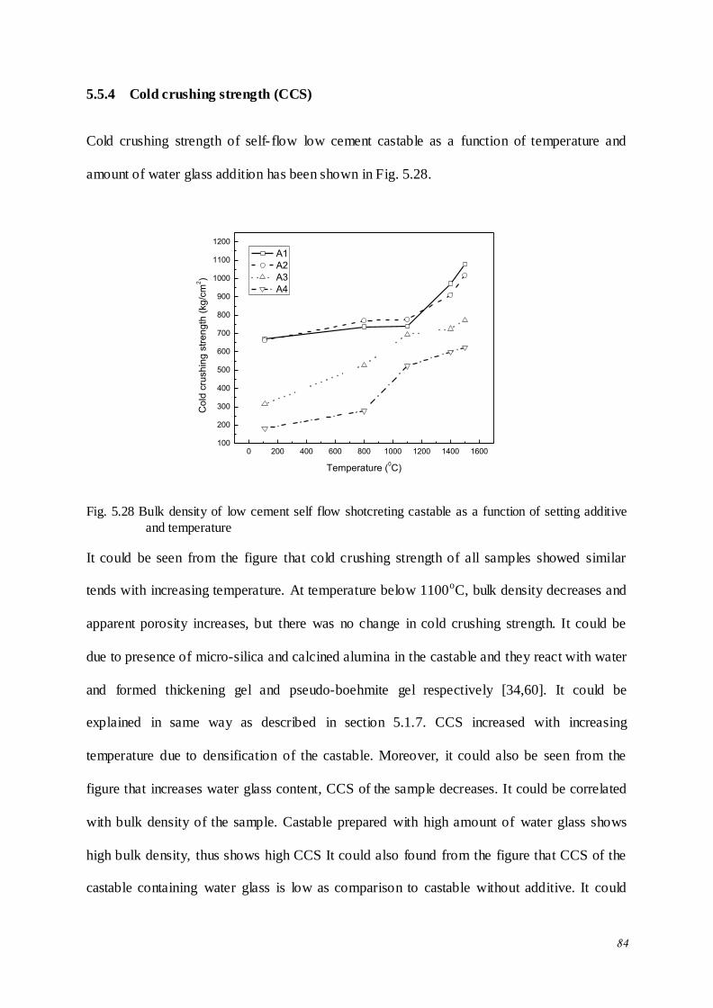
84
5.5.4 Cold crushing strength (CCS)
Cold crushing strength of self- flow low cement castable as a function of temperature and
amount of water glass addition has been shown in Fig. 5.28.
0 200 400 600 800 1000 1200 1400 1600100
200
300
400
500
600
700
800
900
1000
1100
1200
Co
ld c
rush
ing
str
en
gth
(kg
/cm
2)
Temperature (0C)
A1
A2
A3
A4
Fig. 5.28 Bulk density of low cement self flow shotcreting castable as a function of setting additive
and temperature
It could be seen from the figure that cold crushing strength of all samples showed similar
tends with increasing temperature. At temperature below 1100oC, bulk density decreases and
apparent porosity increases, but there was no change in cold crushing strength. It could be
due to presence of micro-silica and calcined alumina in the castable and they react with water
and formed thickening gel and pseudo-boehmite gel respectively [34,60]. It could be
explained in same way as described in section 5.1.7. CCS increased with increasing
temperature due to densification of the castable. Moreover, it could also be seen from the
figure that increases water glass content, CCS of the sample decreases. It could be correlated
with bulk density of the sample. Castable prepared with high amount of water glass shows
high bulk density, thus shows high CCS It could also found from the figure that CCS of the
castable containing water glass is low as comparison to castable without additive. It could
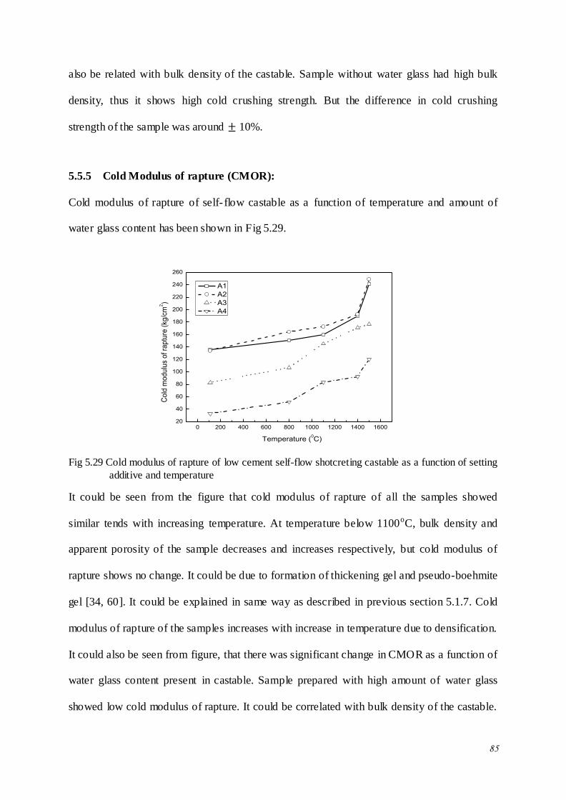
85
also be related with bulk density of the castable. Sample without water glass had high bulk
density, thus it shows high cold crushing strength. But the difference in cold crushing
strength of the sample was around 10%.
5.5.5 Cold Modulus of rapture (CMOR):
Cold modulus of rapture of self- flow castable as a function of temperature and amount of
water glass content has been shown in Fig 5.29.
0 200 400 600 800 1000 1200 1400 160020
40
60
80
100
120
140
160
180
200
220
240
260
Co
ld m
od
ulu
s o
f ra
ptu
re (
kg/c
m2)
Temperature (0C)
A1
A2
A3
A4
Fig 5.29 Cold modulus of rapture of low cement self-flow shotcreting castable as a function of setting
additive and temperature
It could be seen from the figure that cold modulus of rapture of all the samples showed
similar tends with increasing temperature. At temperature below 1100oC, bulk density and
apparent porosity of the sample decreases and increases respectively, but cold modulus of
rapture shows no change. It could be due to formation of thickening gel and pseudo-boehmite
gel [34, 60]. It could be explained in same way as described in previous section 5.1.7. Cold
modulus of rapture of the samples increases with increase in temperature due to densification.
It could also be seen from figure, that there was significant change in CMOR as a function of
water glass content present in castable. Sample prepared with high amount of water glass
showed low cold modulus of rapture. It could be correlated with bulk density of the castable.
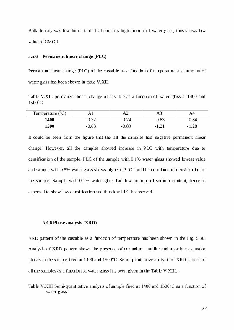
86
Bulk density was low for castable that contains high amount of water glass, thus shows low
value of CMOR.
5.5.6 Permanent linear change (PLC)
Permanent linear change (PLC) of the castable as a function of temperature and amount of
water glass has been shown in table V.XII.
Table V.XII: permanent linear change of castable as a function of water glass at 1400 and
1500oC
Temperature (0C) A1 A2 A3 A4
1400 -0.72 -0.74 -0.83 -0.84
1500 -0.83 -0.89 -1.21 -1.28
It could be seen from the figure that the all the samples had negative permanent linear
change. However, all the samples showed increase in PLC with temperature due to
densification of the sample. PLC of the sample with 0.1% water glass showed lowest value
and sample with 0.5% water glass shows highest. PLC could be correlated to densification of
the sample. Sample with 0.1% water glass had low amount of sodium content, hence is
expected to show low densification and thus low PLC is observed.
5.4.6 Phase analysis (XRD)
XRD pattern of the castable as a function of temperature has been shown in the Fig. 5.30.
Analysis of XRD pattern shows the presence of corundum, mullite and anorthite as major
phases in the sample fired at 1400 and 1500oC. Semi-quantitative analysis of XRD pattern of
all the samples as a function of water glass has been given in the Table V.XIII.:
Table V.XIII Semi-quantitative analysis of sample fired at 1400 and 1500oC as a function of water glass:
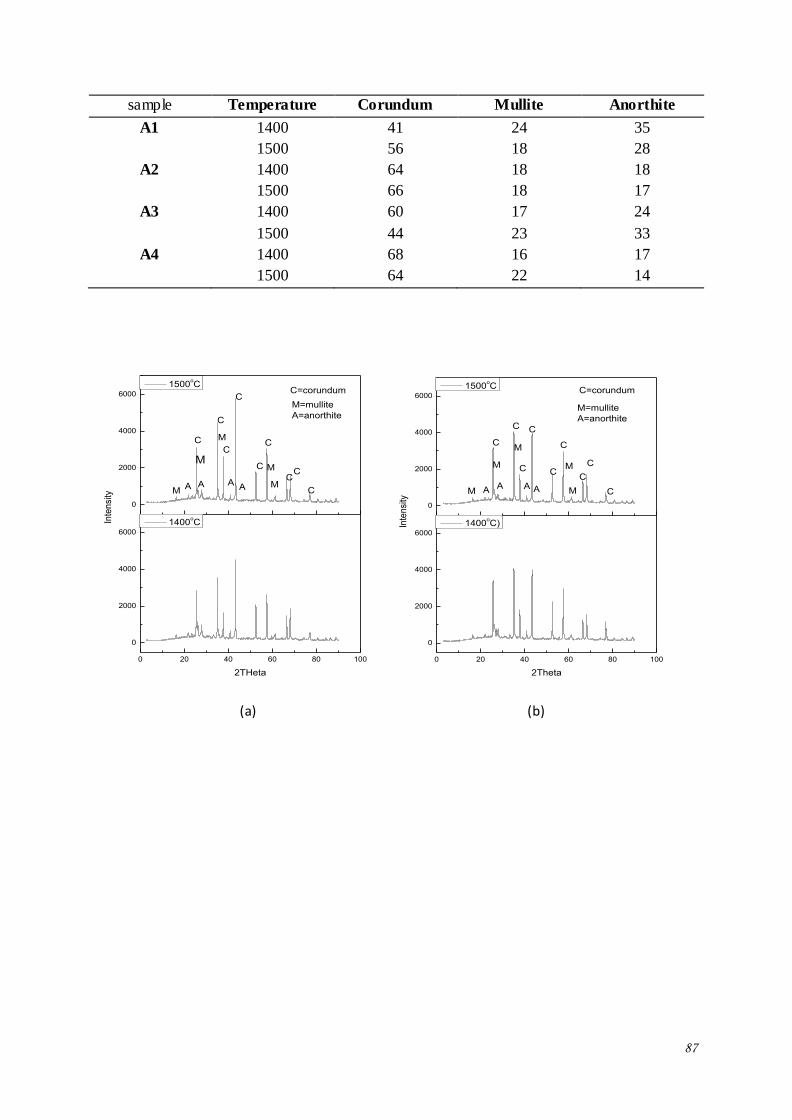
87
sample Temperature Corundum Mullite Anorthite
A1 1400 41 24 35
1500 56 18 28
A2 1400 64 18 18
1500 66 18 17
A3 1400 60 17 24
1500 44 23 33
A4 1400 68 16 17
1500 64 22 14
0 20 40 60 80 100
0
2000
4000
6000
0
2000
4000
6000
A A M
M
A
M
M
2THeta
1400oC
MA
M=mullite
A=anorthite
C
CC
C
C
C
C
C
Inte
nsi
ty
1500oC
C
C=corundum
0 20 40 60 80 100
0
2000
4000
6000
0
2000
4000
6000
AAAM
M
M
M
2Theta
1400oC)
M A
M=mullite
A=anorthite
C
C
C
C
C
C
C
C
Inte
nsi
ty
1500oC
C
C=corundum
(a) (b)
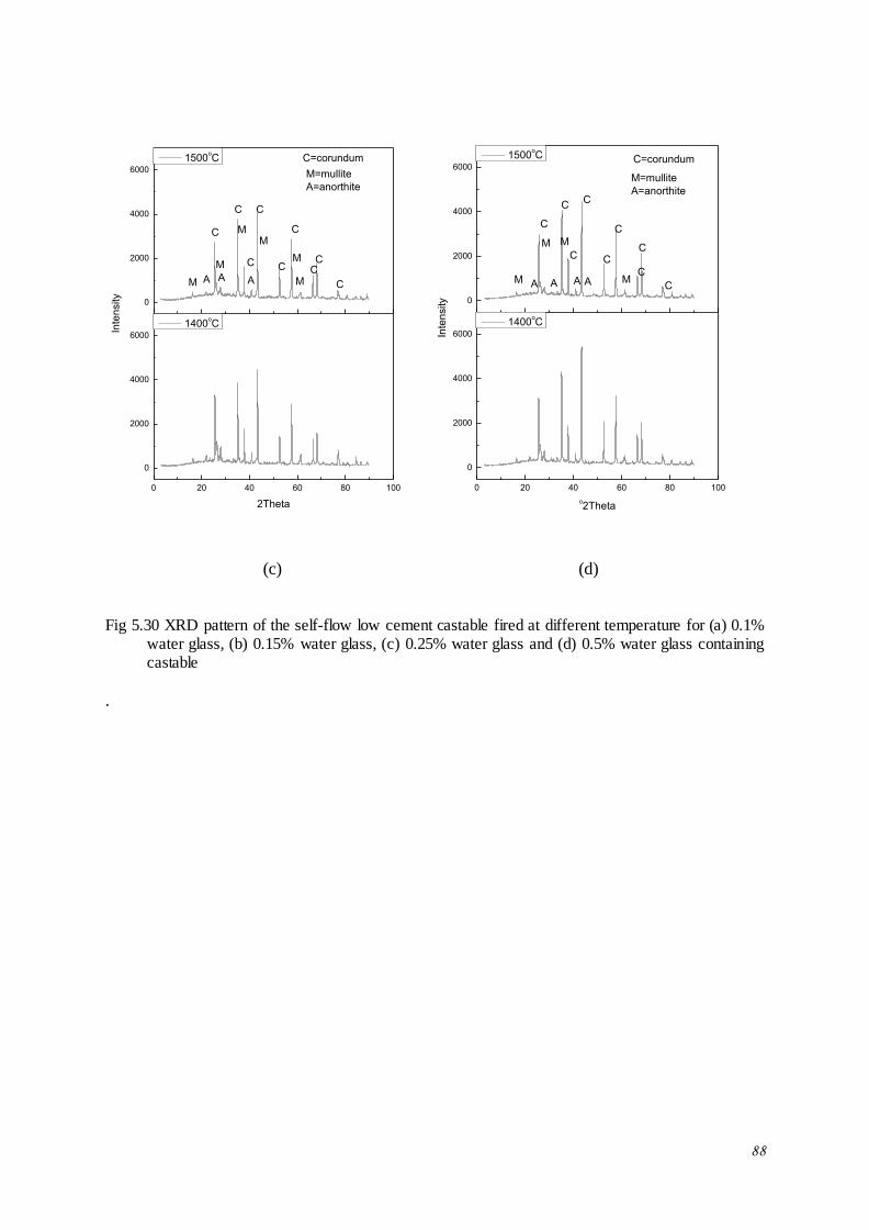
88
0 20 40 60 80 100
0
2000
4000
6000
0
2000
4000
6000
AA M
M
MM
M
2Theta
1400oC
M A
M=mullite
A=anorthite
C
CC
C
C
C
C
C
Inte
nsity
1500oC
C
C=corundum
0 20 40 60 80 100
0
2000
4000
6000
0
2000
4000
6000
AAA M
MM
o2Theta
1400oC
M A
M=mullite
A=anorthite
C
C
C
C
C
C
C
C
Inte
nsity
1500oC
C
C=corundum
(c) (d)
Fig 5.30 XRD pattern of the self-flow low cement castable fired at different temperature for (a) 0.1% water glass, (b) 0.15% water glass, (c) 0.25% water glass and (d) 0.5% water glass containing castable
.
89
CHAPTER -VI
CONCLUSION
90
CONCLUSION
Present study deals with development of 70% Al2O3 low cement vibratable and self- flow
castable. An attempt has also been made to develop a shortcreating mass with the addition of
a set accelerating agent. The study focuses particle size and particle size distribution of
calcined alumina filler on the flow behaviour of the LCC, optimization of amount of calcined
alumina and micro-silica content of a self- flow castable body formulation in order to achieve
flow at low water content. Physical and mechanical properties of the optimized self- flow
castable has also been studied as a function of set accelerating agent. The following
conclusion could be achieved from the present study.
1) Studies on the particle size and particle size distribution of calcined alumina filler
on the properties of 70% Al2O3 low cement vibratable castable:
a. The flow behaviour of the castable depends strongly on the particle size distribution
rather than that of the particle size of the filler alumina powder. This behaviour could be
related to the filling up the voids of aggregates in the castable with the filler particle.
b. Apparent porosity and bulk density also depends particle size and particle size
distribution of the filler alumina particle and could be attributed to packing density of
castable. However apparent porosity and bulk density of the castable increases and
decreases respectively with temperature up to 1100oC due to de-hydroxylation of cement
hydrates thereafter it follows’ reverse tends due to densification.
c. Cold crushing strength and modulus of rapture of the castable depends up on particle size
of the filler alumina particle rather than the particle size distribution. Castable prepared
with fine calcined alumina filler (having high surface area) showed high CCS and
CMOR. CCS and CMOR increases with temperature due to formation of pseudo-
91
bheomite phase and thickening gel at intermediate temperature range and at high
temperature it increase due to sintering.
d. Permanent linear change of the castable also depends on particle size and particle size
distribution of filler alumina. It is mostly dependent of the particle size distribution rather
than that of particle size. This behaviour could be attributed to the bulk density and
porosity of the sample. Castable samples with high bulk density showed low PLC value.
2) Studies on the effect of micro-silica amount on 70% Al2O3 self-flow low cement
castable:
a. Water percentage of the castable decreased with increase in micro-silica up to 8% further
increase in micro-silica content water requirement value increased. This could be
correlated with the filling of the voids of the aggregates with the micro fine silica filler.
b. Apparent porosity and bulk density of the castable depends on the amount of micro silica
content. Apparent porosity decreases and bulk density increases with increase in micro-
silica content upto 8% addition thereafter it follows a reverse trend. This could be related
to the filling up of the aggregate voids by micro-silica and hence the water requirements
of the castable for 100% flow.
c. Cold crushing strength and cold modulus of rapture depends on amount of micro silica
content. Cold crushing strength and cold modulus of rapture increases with increase in
micro-silica content up to 8% addition thereafter it decreases. This could be related to
the filling up of the aggregate voids by micro-silica and hence the water requirement of
the castable to achieve 100% flow.
92
3) Studies on the effect of calcined alumina content on the 70% Al2O3 self-flow low
cement castable
a. Water requirement for castable decreases with increasing the amount of calcined alumina
up to 10% further increase in calcined alumina content water requirement increases. It
could be related with the filling the voids of the aggregate with fine calcined alumina.
b. Apparent porosity and bulk density of the castable depends on the micro-silica content.
Apparent porosity and bulk density of the castable decreases and increases respectively
with increase the amount of calcined alumina up to 10% thereafter, it decreases. It could
be correlated with filling the voids of the aggregate and hence with the water requirement
to achieve 100% flow.
c. Cold crushing strength and cold modulus of rapture of the castable depends on micro-
silica content. CCS and CMOR increases with increase in Micro-silica content up to
10%. It could be correlated with the filling the voids of the aggregate hence with water
requirement and bulk density.
4) Studies on the effect of quick setting additive on the 70% Al2O3 self-flow low cement
castable :
a. With increase in the amount of quick setting additive setting time deceases
exponentially. Setting additive solution in water form a gel and it was dehydrate by air
drying and gave quick setting. 0.25 to 0.15% amounts of quick setting additives may be
suitable for shotcreting technique.
b. Samples prepared with high amount of setting agent showed inferior properties. This
may be related with the short casting time which leads to fabrication of samples with
inferior properties.
93
REFERENCES
1. LI Zaigeng and ZHOU Ningsheng, “Technology Advancement in Preparation and
Application of Monolithic Refractory” China’s Refractory, vol. 10 No. 1, (2001), 3-10.
2. ZHOU Ningsheng, HU Shuhe and ZHANG Sanhua, “Advances In Monolithic
Refractory Castable” China’s Refractory, Vol. 13 No. 2, (2004), 3-12.
3. Plibrico, “Technology of monolithic refractory”.
4. Charles A. Schacht, “Refractories Handbook”, Marcel Dekker, Inc., New York- Basel,
(2004)
5. Christopher Parr, Fabien Simonin, Bruno Touzo, Chistoph Wohremeyer, Benoit
Valdelievre and Akihiko Namba, “The Impact of Calcium Aluminate Cement
Hydration Upon the Properties of Refractory Castable” Journal of the Technical
Association of Refractories, Japan, 25 [2], (2005), 78-88.
6. Nilforoushan, Mohammad Reza and Talebiaan, Nasr ien, “The Hydration Products of a
Refractory Calcium Aluminate Cement at Low Temperatures” Iran. J. Chem. Chem.
Eng. Vol. 26, No.2, (2007), 71-76.
7. Nicolas Schmitta, Jean-Franciois Hernandeza, Vincent Lamoura, Yves Berthauda,
Pierre Meunierc, Jacques Poirierd, “Coupling Between Kinetics of Dehydration,
Physical and Mechanical Behaviour for High Alumina Castable” Cement and Concrete
Research 30, (2000), 1597- 1607.
8. Paulo Cesar Evangelista, christopher Parr and Cetharine Revais, “control of
formulation and optimization of self- flow castable based on calcium aluminate cement”
refractory application and news, Vol 7, No 2, (2002), 14-18.
94
9. Ye Guotian and Li Zaigeng, “trend in monolithic refractories technology” chiana’s
refractory vol 8, no 3, (1999), 15-18.
10. A.R. Studarta, V.C. Pandolfellia, E. Tervoortb, L.J. Gauckler, “Selection of dispersants
for high-alumina zero-cement refractory castables” Journal of the European Ceramic
Society 23 (2003) 997–1004.
11. Y. A. Marques and R. G. Pileggi, “Setting Additive influence on the
Thermomechanical Propperties of Wet Shotcrete Refractory castable Matrices”
American ceramic society bulletin, August (2005), 9201 – 9206.
12. Bjorn Myhre and Aase M. Hundere, “The Use of Par ticle Size Distribution in
Development of Refractory Castable” Presented at XXV ALAFAR Congress, Dec. 1-4,
(1996).
13. Aase Hundere, Bjorn Myhre and Bjorn Sandberg, “Free-flowing castable – a
prerequisite for wet-gunning of refractory castable” Presented at the VIIth International
Matallugical Conference in Ustron, Poland, May (1997).
14. A. H. M. Andreassen and J. Andersen, Kolloid Z, 50, (1930), 217-228.
15. D. R. Dinger and J. E. Funk, Interceram 41, (1992), [1] 10-14.
16. S. Ganguli "Influence of particle size distribution on flow, microstructure and some
special monolithic” (2008).
17. B. Myhre, “Particle Size Distribution and its relevance Refractory Castable” In Proc.2nd
Indian Int. Ref. Con., New Dehli, India, Vol. I, (1996), 47-56.
18. Y. Kutmen Kalpakli, “Effect of particle size distribution on the refractory properties
and corrosion mechanism of ultra –low cement castable,” vol.34 [2], December (2008),
81-88.
95
19. E. Karadeniz, C. Gurcan, S. Ozgen and S. Aydin, “Properties of Alumina based Low
Cement Self- flow Castable refractory” Journal of the European Ceramic Society 27,
(2007), 1849-1853.
20. Toshisiko Kando, Satoshi Terayama, Katsuaki Funato, Tsuyoshi Okamato and Seijiro
Tanaka, “relation between grain size distribution and fludity of refractory castable”
Journal of the Technical Association of Refractories, Japan, 100.
21. Aya Kusunoki, Yoshitaka Sadatomi, Yoshihiro Sasatani and Tsubasa Nakamichi,
“Effect of particle size distribution on the fluidity of alumina magnesia system
castable” Unitecr (2011), 1-D-6.
22. S. Ganguli, S. Satapathy, A. K. Samanta, S. Adak, P.B. Panda, “Development of
castable in Al2O3-MgAl2O4 system” 2nd ICRJ, , (2010), 161-167.
23. Rafael Salomao and Victor C. pandofelli, “particle size distribution effect on the drying
efficiency of polymeric fibers containing castables” Ceramic international 34, (2008),
173-180.
24. Subrata Banerjee, “Monolithic Refractories” Answer Technology Inc. Illinois USA.
25. Christopher Parr, Catherine Revais, Nancy Bunt and Duncan Jones, “Ageing of
Refractory Castable” Unitcer vol. 1 (1997); 81-90
26. Jason M. Canon, Todd P. Sander, Jeffrey D. Smith and Robert E. Moore, “the effect of
organic fibre addition on permeability of refractory concrete”, Unitecr vol. 2, (1997),
583 – 592.
27. Yozo Yukino, Nobuyuki Takahashi and Makoto Ishikawa, “Effects of Curing and
Drying Conditions On Properties of Low Cement Castable” Unitecr (2003), 276- 279.
28. R. Saloma˜o, F.A. Cardoso, M.D.M. Innocentini, L.R.M. Bittencourt, V.C. Pandolfelli,
“Effect of polymeric fibers on refractory castables permeability”, Am. Ceram. Soc.
Bull. 82 (4) (2003) 51–56.
96
29. Hong Peng and Bjorn Myhre, “Effect of dispersant and raw materials on placing
properties and shelf life of bauxite based low– and ultra-low cement castable” Aachen
(2010), 62 – 65.
30. I.R. Oliveira, V.C. Pandolfelli, “Does a tiny amount of dispersant make any change to
refractory castable properties?” Ceramics International 36, (2010), 79–85
31. Hiroshi Shikona, Jyouki Yoshitomi, Mitsuo Kanda, Sotoyuki Kirinati, Masataka Sato
and Yukio Sasagawa, “role of silica flour in low cement castable” Taikabutsu Overseas
Vol. 10, No. 1, 17-22.
32. Alani Mathieu, Alani Capmas, Jean pierre Bayoux and Denis Richon, “Calcium
aluminate cement and reactive alumina” unitecr (1997), 672-682.
33. Toshihide Yumoto, Toshihiko Kondo, Matsuiti Yoshimura, Shichi Hitomi and Yukio
and Yukio Oguti, “effect of content of Alumina cement, Silica flour and added water on
strength of castable”, Taikabutsu Overseas, Vol. 13 No.2, (1993), 3-6.
34. Dr. A. K. Samanta, S. Satpathy, Dr. S. Adak and Dr. A. K. Chattopadhyay, “Effect of
Calcium Aluminate Binder and Microsilica on Thermo-Mechanical Properties of Low
Cement Castables”, unitecr (2011), 31-D 11.
35. B.Myhre, A.M. Hundere and H. Feldborg, “Corelation between mullite formation and
mechanical properties of refractory castable at elevated temperatures,” VIII Int. Met.
Conf., Ustron, Poland May, (1999), 25-28
36. Aase M. Hundere and Bjorn Myhre, “Mullite Bonded Castable” Proc. Am.Ceram. Soc,
Ohio, (1997).
37. Lu Yichum and Li Ziageng, “Study of self bonded high performance mullite castable”
China’s refractory vol. 5 No. 4; (1996), 27-34.
38. Joseph S. Masaryk, Richard A. Setinke and Ralph B. Videtto, “development and use of
low cement castable, self- flow castable” unitecr (1993), 527-538.
97
39. Koji Ide, Minoru Kataoka, Kazuhiro Furut, Yoshiaki Kawase, Fokuyashi Isomura,
Kenji Nakao, Shigeru Mino and Yoshitaka Senno, “Development of a self- flow
castable for steel ladles” Taikabutsu Overseas, vol.17 No.1 (1996), 53-57.
40. Aase Hundere, Bjorn Myhre and Bjorn Sandberg, “Free flowing castable- a prerequisite
for wet gunning of refractory castable”, Presented at the VII-th International
Metallurgical Conference in Ustron, Poland, May (1997), 1- 11.
41. Chen Zhiquang, “Flow and flow decay of refractory castable” China’s refractory, vol
12, No 4, (2003), 16-19.
42. R. Sarkar and A. Mishra, “High-Alumina self- flow castable with different cement
binder”, Interceram [2] (2012), 107-111.
43. Bejorn Myhre, “micro-silica in alumina based low cement castable. the effect of micro-
silica addition on flow” presented at XXIII ALAFAR congress, in Puerto Vallarta,
Mexico Nov. (1994).
44. Bjorn Myhre, “The effect of microsilica on the flow and strength of alumina castable”
American Ceramic Society, april, 18-22, (1993).
45. Hong Peng, Jian Li and Biorn Myhre, “Effect of micro-silica on properties of
corundum-mullite self- flow ultra low cement castable”, 7th India international
refractories congress 2008, 177-182. Bjorn Myhre and Aase M. Hundere, “Substitution
of reactive alumina with microsilica in low cement and ultra low cement castable, Part
1: properties related to installation and demoulding” Unitecr (1997), 43- 52.
46. Bjorn Myhre and Aase M. Hundere, “Substitution of reactive alumina with microsilica
in low cement and ultra low cement castable, Part 1: properties related to installation
and demoulding” Unitecr (1997), 43- 52.
98
47. Aase Marie Hundere and Bjorn Myhre, “Substitution of reactive alumina with
microsilica in low cement and ultra low cement castable, part 2: The effect of
temperature on hot properties” Unitecr (1997), 91- 100
48. Vicki Jones, “Flow control of low cement self- flow castables”, unitecr, vol 2, (1997),
635-644.
49. R. G. Pileggi, Y. A. Marques, D. Vasques Filho, V. C. Pandolfelli, N. Moreira And
S.C. Frasson, “Evaluating the Shotcrete Performance of Refractory Castables”,
Proceedings of the 47th Annual Meeting of the Brazilian Ceramic Society 15-18June,
(2003), 162-174.
50. Koji Watanabe, Makot Ishikawa and Mitsuru Wakamatsu, “Rehology of castable
refractories” Taikabutsu overseas vol. 9[1] 41-53.
51. Liu Xinhong, Feng Long, Ye Fangboa and Zhong Xiangchong, “some influencing
factor on rheological property of bauxite based castable matrix” China’s refrctory,
vol.21, No. 3, (2012), 20-24.
52. R.G. Pileggi, Y.A. Marques, D. Vasques Filho and V.C. Pandolfelli, “Shotcrete
performance of refractory castable” refractories application and news, volume 8,
number 3 May/June (2003), 15-20.
53. ACI committee 506, “guide to shotcrete,” American Concrete Institute, ACI 506R-90
Third Printing, January (1994), pp. 3, sec. 1.5.
54. William G. Allen, “advanced equipment system for refractory placement” unitecr vol 2,
(1997), 523-530.
55. Aase Hundere, Bjørn Myhre, Cecilie Ødegård and Bjørn Sandberg “wet shotcreting
refractory castables with varying cement content” XIII Conference on Refractory
castables Nov. (1998), 4-5.
99
56. Zhanimin Wang, Sanhua Zhang, Xiying Cao, Xia He and Zhengyong Bi, “Flowability
and flocculation of wet gunning castables with different additives” Unitecr (2005), 413-
418.
57. Eiji Motoki and Nobuki Tanaka, “Evaluation of quick setting additives for wet gunning
installing” journal of technical associaltion of Refractory, 21 [2] (2001); 111-115.
58. Jinfu Yao, Shouxin Tian, Feifang Gan, Feng Wang, Zhenjun Liu Juyuan Chen Li
Zhang and Li Tang, “research on asc hot shotcreting castable” unitecr, (2005), 484-488.
59. Chia-Hong Chen, “Application and Research of Wet-gunning Based on Colloidal silica
for Main trough of Blast Furnace”, unitecr , (2011), 2-B2-19
60. M. Nouri-Khezrabada, M.A.L.Brauliob, V.C.Pandolfellib, F.Golestani-Farda and H.R.
Rezaie, “Nano Bonded Refractory Castable” Ceramics International 39 (2013), 3479–
3497