digital multimeter operation manual - crenova · -2-switchingandadigitaldisplaydriveoffering...
TRANSCRIPT
RAGU 81D DIGITALMULTIMETEROPERATIONMANUAL

ContentsI. General...................................................- 1 -Ⅱ. Open-package Inspection....................- 2 -III. Safety Considerations......................... - 3 -IV.Instrument Panel & Button FunctionDescription................................................ - 9 -V. Other Functions.................................. - 12 -VI、Property...........................................- 13 -
1.General Property ......................- 13 -2.Technical Property.................... - 14 -
2-2-1. DCV.............................- 15 -2-2-2. ACV True RMS........... - 16 -2-2-3. DCA.............................- 18 -2-2-4. ACATrue RMS........... - 20 -2-2-5. Resistance (Ω)............. - 23 -2-2-6.Diode and Continuity Test- 25 -2-2-7. Capacity (C).................- 28 -2-2-8. Frequency (F).............. - 29 -2-2-9. Temperature (℃/℉).... - 31 -
VII. Instrument Maintenance.................. - 33 -VIII. Fault Elimination............................- 36 -

I. General
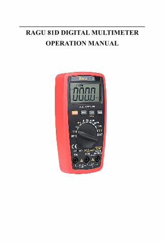
The RAGU 81D digital multimeter,equipped with the LCD display of text height18.9mm, is a 3 3/4 digital multimeter whichhas merits of clear reading, stableperformance and high reliability.
It could be used to measure DC voltage,AC voltage, DC current, AC current,resistance, temperature, capacity, frequency /duty cycle, diode and to make on-and-off test.Meanwhile, it is available for unit symboldisplay, automatic/manual range switching,automatic power off and alarm function. Thecomplete machine takes an integrated circuitwhich can directly drive LCD 8-bitmicroprocessor and double-integrating A/D
- 2 -
switching and a digital display drive offeringhigh resolution and high precision. Due to itscomplete functions, high measurementaccuracy and convenient operation, themultimeter is the ideal tool in laboratory andfactory as well as for radio fans and family.
Ⅱ. Open-package Inspection
Open the package box and take out the meter,check carefully if the following accessoriesare absent or damaged. If there were anyabsence or damage, please contact thedistributor immediately.Digital Multimeter 1 PCInstruction Manual 1 copyTest Leads 1 pairTemperature Probe (K-Thermocouple) 1 PC
- 3 -
AAA (1.5v) 7# batteries 2 PCs
III. Safety Considerations
The design of meter is in accordancewith IEC1010 clause (the safety standardissued by International ElectrotechnicalCommission). Prior to the operation of theinstrument, please read the safetyconsiderations first.1. When DC voltage is higher than 30V, ACvoltage is higher than 25V, current ishigher than 10mA, AC power line withinductive load or power line during electricfluctuation is measured. Please beware ofelectric shock.
2. Prior to measurement, check if themeasurement function switch is at the
- 4 -
correct position. Check if the test lead iscontacted reliably, connected correctly, andgrounded well and etc. in order to avoidelectric shock.
3. Only if the meter is used with the matchedtest lead, can it meet the requirements ofsafety standard. When the line of the testlead is damaged, it is necessary to replaceanother one of the same model or the sameelectrical specification.
4. Don’t use other unconfirmed ordisapproved fuse to replace the originalone inside the meter. Only the fuse of thesame model or same specification can bereplaced. Before the replacement, the testlead must leave the measuring point andensure there is no any signal at the input

- 5 -
terminal.5. Don’t use other unconfirmed ordisapproved batteries to replace thebatteries inside the meter. Only thebatteries of the same model or sameelectrical specification can be replaced.Before the replacement, the test lead mustleave the measuring point and ensure thereis no any signal at the input terminal.
6. When the electrical measurement is made,never let your body get in touch with theground directly, and don’t touch uncoveredmetal terminal, output port, lead clamp etc.Dry clothes, rubber shoes, rubber cushionand other insulating material are usuallyused to keep your body insulated againstthe ground.

- 6 -
7. Don’t store and use it in thehigh-temperature, high-humidity,inflammable environment and strongmagnetic field.
8. It may cause damage to the meter andendanger the operator’s safety if you takeany voltage measurement that exceedsthe limits. The ultimate voltage valuepermitted for measurement is marked onthe instrument panel. Never takemeasurement or input the ultimate valuewhich exceeds the standard in order toavoid electric shock and damage to themeter.
9. When the test lead is inserted into thecurrent socket, don’t take any voltage
- 7 -
measurement to prevent damaging themeter and endangering the operator’ssafety.
10. Don’t try calibrating or repairing themeter. When necessary, only the qualifiedprofessional personnel who have hadspecial training or gained approval canmake it.
11. During measurement, the requirement ofmeasurement function must be inaccordance with LCD display. Please besure to disconnect the line of the test leadswith the measured object first and ensurethere is no any input signal. It is forbiddento switch the function/range selection

- 8 -
switch during measurement.12. When “ ”is shown on LCD display,
please replace battery immediately toensure the measurement precision.
13. It is not allowed to insert the test lead intothe current terminal to measure voltage!
14. Please don’t change the circuits of themeter by yourself to prevent damagingthe meter and endangering theoperator’s safety.
15. Description of Safety Symbols
- 9 -
F
Hz
FUSED400mA MAX
mAVCOM10A
C
Hz
1
2
3-13-2
3-33-4
4
5-1
5-2 5-3
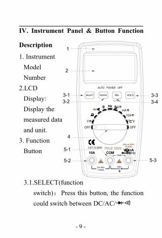
IV. Instrument Panel & Button Function
Description
1. InstrumentModelNumber
2.LCDDisplay:Display themeasured dataand unit.
3. FunctionButton
3.1.SELECT(functionswitch):Press this button, the functioncould switch between DC/AC/

- 10 -
3.2.RANGE(auto/manual range switch):The meter is in automatic range when starts
up, press the “RANGE” button to activate
manual range mode. In the mode of manual
range, each press lets the meter skip to the
previous shift. When it goes to the highest
shift, it goes back to the lowest shift
automatically. The procedure repeats again
in the same order. Press the “RANGE”
button over 2 seconds, it will exit from
manual range measurement mode and shift
to automatic range measurement mode.
3.3. HOLD(Data Hold):Press this button,the reading shall be hold and kept onLCD; Press it again, the meter entersinto normal measurement status.

- 11 -
3.4 REL (Relative Value Measurement):The relative value measurement of allfunctions could be conducted bypressing this button except the Hz/Dutyfunction. Frequency/duty cycle: pressthis button to select frequency or dutycycle measurement mode.
4.Function/Range Selection Switch:It couldbe used to change the measurementfunction and range.
5. Input Terminals5.1.Current, Voltage, Diode, Resistance,
Capacity, Frequency, Buzzer,Temperature“-”Input terminal.
5.2.10A“+”input terminal.

- 12 -
5.3.Voltage、Diode、Resistance, Capacity,Frequency, Buzzer, Temperature and“+”Input terminal with current less than400mA.
V. Other Functions
Automatic Power offDuring measurement, the meter willautomatically shut down (enter sleepingmode) to save power if function buttons andfunction/range selection switch are notoperated in 15 minutes. In auto power offmode, press any function buttons or rotate thefunction/range selection switch, theinstrument will get into the auto power onmode (working mode); the auto power offmode will be canceled by pressing the
- 13 -
SELECT button to turn on the instrument.
VI、Property
1.General Property1-1. Display:LCD1-2. Max Display: 3999( 3 3/4) counts
automatic polarity display and unitdisplay
1-3. Measuring Method:Dual integral A/Dconverter
1-4. Sampling Rage:Approx. 3 times / sec.1-5. Over Range Indication:Display“OL”1-6. Low Battery Indication:“ ”symbol
appears;1-7.Operation Environment: (0~40)℃,
Relative Humidity: <80% ;
1-8. Storage Environment: (0~ 50)℃,

- 14 -
Relative Humidity: <80% ;
1-9.Power: 2pcs 1.5V batteries (“AAA”7#battery)
1-10.Dimension (size): 145×74×36mm1-11.Weight: Approx. 190g(Including 2pcs
1.5V batteries)1-12.Accessories: Instruction Manual (1 pc),
Holster (1 pc), Outer packing box (1 pc),10A test leads (1 pair), K-Thermocoupleand 1.5V batteries (2 pcs).
2.Technical Property2-1. Accuracy:±(a%×reading+number ofdigits),at (23±5)℃,relative humidity <
75%. Warranty is one year, starting on shipping
date.
2-2.Technic Specification
- 15 -
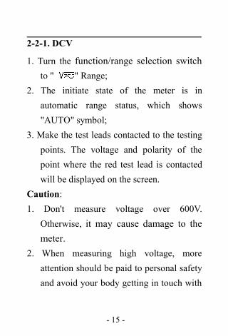
2-2-1. DCV
1. Turn the function/range selection switchto " " Range;
2. The initiate state of the meter is inautomatic range status, which shows"AUTO" symbol;
3. Make the test leads contacted to the testingpoints. The voltage and polarity of thepoint where the red test lead is contactedwill be displayed on the screen.
Caution:1. Don't measure voltage over 600V.
Otherwise, it may cause damage to themeter.
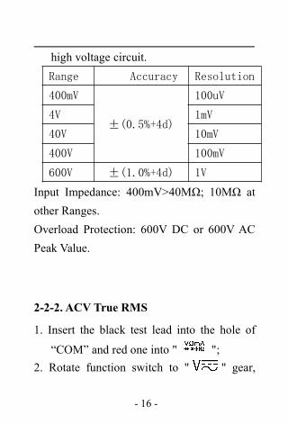
2. When measuring high voltage, moreattention should be paid to personal safetyand avoid your body getting in touch with
- 16 -
high voltage circuit.Range Accuracy Resolution
400mV
±(0.5%+4d)
100uV
4V 1mV
40V 10mV
400V 100mV
600V ±(1.0%+4d) 1V
Input Impedance: 400mV>40MΩ; 10MΩ atother Ranges.Overload Protection: 600V DC or 600V ACPeak Value.
2-2-2. ACV True RMS
1. Insert the black test lead into the hole of
“COM” and red one into " ";2. Rotate function switch to " " gear,

- 17 -
press “SELECT” button to select the ACmeasurement mode.
3. The initiate state of the meter is inautomatic range status, which shows“AUTO" symbol;
4. Make the test leads contacted to the testingpoints. The voltage of the point where thered test lead is contacted will be displayedon the screen.
Caution:1. Don't measure voltage over 600V.
Otherwise, it may cause damage to themeter.
2. When measuring high voltage, moreattention should be paid to personal safetyand avoid your body getting in touch withhigh voltage circuit.

- 18 -
Range Accuracy Resolution
4V
±(0.8%+6d)
1mV
40V 10mV
400V 100mV
600V ±(1.0%+6d) 1V
Input Impedance: >10MΩ;Overload Protection: 600V DC or 600V ACPeak Value;Frequency Response: (50~200) Hz;Display: Average value response (RMS ofsine wave).
2-2-3. DCA
1.Insert the black test lead into the "COM"
input terminal and red one into the " "input terminal(Max 400mA), or 10A input
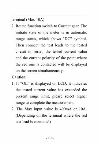
- 19 -
terminal (Max 10A).2. Rotate function switch to Current gear. Theinitiate state of the meter is in automaticrange status, which shows "DC" symbol.Then connect the test leads to the testedcircuit in serial, the tested current valueand the current polarity of the point wherethe red one is contacted will be displayedon the screen simultaneously.
Caution:1. If “OL” is displayed on LCD, it indicatesthe tested current value has exceeded thepresent range limit, please select higherrange to complete the measurement.
2. The Max input value is 400mA or 10A.(Depending on the terminal where the redtest lead is contacted)

- 20 -
Range Accuracy Resolution
400uA
±(1.0%+10d)
0.1uA
4000uA 1uA
40mA 10uA
400mA 100uA
10A ±(1.2%+10d) 10mA
Max measurement voltage drop: Full RangemA is 0.4V, A is 100mV;Max input current: 10A (less than 15seconds);Overload Protection: 0.4A/250V restorablefuse, 10A/250V fuse.
2-2-4. ACATrue RMS
1. Insert the black test lead into the "COM"input terminal and red one into the "
" input terminal(Max 400mA), or
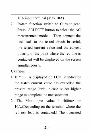
- 21 -
10A input terminal (Max 10A).2. Rotate function switch to Current gear.
Press “SELECT” button to select the ACmeasurement mode. Then connect thetest leads to the tested circuit in serial,the tested current value and the currentpolarity of the point where the red one iscontacted will be displayed on the screensimultaneously.
Caution:1. If “OL” is displayed on LCD, it indicatesthe tested current value has exceeded thepresent range limit, please select higherrange to complete the measurement.
2. The Max input value is 400mA or10A.(Depending on the terminal where thered test lead is contacted.) The overrated

- 22 -
current will lead to fuse melt or evendamage the meter.
Range Accuracy Resolution
400uA
±(1.5%+10d)
0.1uA
4000uA 1uA
40mA 10uA
400mA 100uA
10A ±(2.5%+15d) 10mA
Max measurement voltage drop: Full RangemA is 0.4V, A is 100mV; Max input current:10A (less than 15 seconds);Overload Protection: 0.4A/250V restorablefuse,10A/250V fuse;Frequency Response: True RMSresponse(50~200)Hz.

- 23 -
2-2-5. Resistance (Ω)
1. Insert the black test lead into "COM"
terminal and red one into " " terminal.2. Rotate the Range to “Ω” gear. Cross
connect the test leads to the tested resistor.3. When measuring the low resistance, pleaseshort-circuit the test leads at first to test thewire resistance, and then deduct it from theactual resistance.
Caution:1. If “OL” is displayed on LCD, it indicatesthe tested resistance value has exceededthe present range limit, please select higherrange to complete the measurement. Whenmeasuring the Resistor higher than 1MΩ,the instrument will take several seconds tomake the reading stable. It is normal when
- 24 -
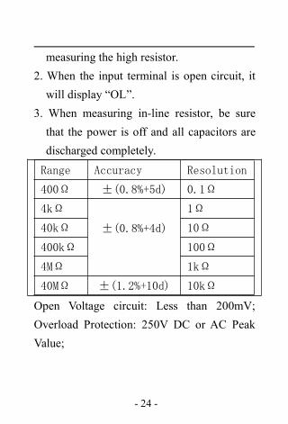
measuring the high resistor.2. When the input terminal is open circuit, itwill display “OL”.
3. When measuring in-line resistor, be surethat the power is off and all capacitors aredischarged completely.
Range Accuracy Resolution
400Ω ±(0.8%+5d) 0.1Ω
4kΩ
±(0.8%+4d)
1Ω
40kΩ 10Ω
400kΩ 100Ω
4MΩ 1kΩ
40MΩ ±(1.2%+10d) 10kΩ
Open Voltage circuit: Less than 200mV;Overload Protection: 250V DC or AC PeakValue;

- 25 -
Note:When measuring at Range 400Ω, pleaseshort-circuit the test leads at first to test thewire resistance, and then deduct it from theactual resistance.
2-2-6.Diode and Continuity Test
1. Insert the black test lead to “COM”
terminal and the red one to “ ”
terminal. (The polarity of red test lead is“+”);
2. Rotate the Range to " " gear. Press“SELECT” button to select the Diodemeasurement mode;
3. Forward Measurement: Connect the redtest lead to the diode positive polarity and

- 26 -
the black one to the diode negative polarity.The approximate value of diode forwardvoltage drop will show on the display.
4. Backward Measurement: Connect the redtest lead to the diode negative polarity andthe black one to the diode positive polarity."OL" symbol will be displayed on thescreen.
5. The complete diode testing includesforward and backward measurement, if theresult does not meet the above; it meansthe diode is bad.
6. Press “SELECT” button to select theContinuity measurement mode.
7. Connect the test leads to two points of thetested circuit. If the built-in buzzer sounds,the resistance between the two points is

- 27 -
less than 50Ω.
Range Display Test Condition
ForwardVoltage Dropof Diode
Forward DCCurrent is Approx.0.5mA, BackwardVoltage is Approx.1.5V
Buzzer makesa long soundif resistance isless than 50Ω
Open circuitvoltage is Approx.0.5V
Overload Protection: 250V DC or AC PeakValue.CAUTION: DO NOT INPUT VOLTAGE ATTHIS RANGE!
- 28 -
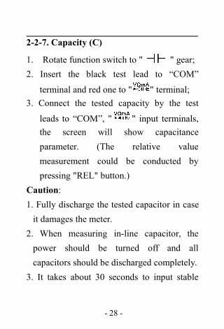
2-2-7. Capacity (C)
1. Rotate function switch to " " gear;2. Insert the black test lead to “COM”
terminal and red one to " " terminal;3. Connect the tested capacity by the test
leads to “COM”, " " input terminals,the screen will show capacitanceparameter. (The relative valuemeasurement could be conducted bypressing "REL" button.)
Caution:1. Fully discharge the tested capacitor in caseit damages the meter.
2. When measuring in-line capacitor, thepower should be turned off and allcapacitors should be discharged completely.
3. It takes about 30 seconds to input stable
- 29 -
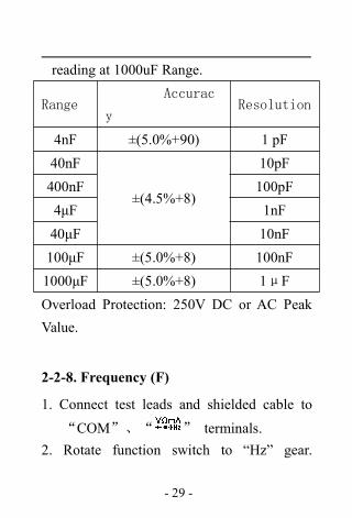
reading at 1000uF Range.
RangeAccurac
yResolution
4nF ±(5.0%+90) 1 pF40nF
±(4.5%+8)
10pF400nF 100pF4μF 1nF40μF 10nF100μF ±(5.0%+8) 100nF1000μF ±(5.0%+8) 1μFOverload Protection: 250V DC or AC PeakValue.
2-2-8. Frequency (F)
1. Connect test leads and shielded cable to
“COM”、“ ” terminals.2. Rotate function switch to “Hz” gear.
- 30 -
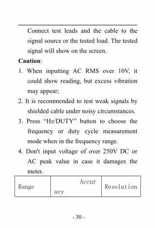
Connect test leads and the cable to thesignal source or the tested load. The testedsignal will show on the screen.
Caution:1. When inputting AC RMS over 10V, it
could show reading, but excess vibrationmay appear;
2. It is recommended to test weak signals byshielded cable under noisy circumstances.
3. Press “Hz/DUTY” button to choose thefrequency or duty cycle measurementmode when in the frequency range.
4. Don't input voltage of over 250V DC orAC peak value in case it damages themeter.
RangeAccur
acyResolution
- 31 -
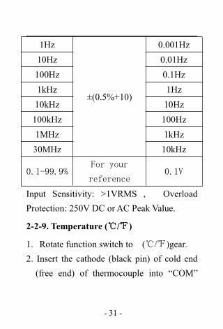
1Hz
±(0.5%+10)
0.001Hz10Hz 0.01Hz100Hz 0.1Hz1kHz 1Hz10kHz 10Hz100kHz 100Hz1MHz 1kHz30MHz 10kHz
0.1-99.9%For your
reference0.1V
Input Sensitivity: >1VRMS , OverloadProtection: 250V DC or AC Peak Value.
2-2-9. Temperature (℃/℉)
1. Rotate function switch to (℃/℉)gear.2. Insert the cathode (black pin) of cold end(free end) of thermocouple into “COM”

- 32 -
jack and anode into “ ” terminal. Thenput the working end (temperaturemeasurement end) of thermocouple on thesurface or inside the object to be tested.Then you can read temperature from thescreen, and the data is in Centigrade.
Caution:1. When the input terminal is open-circuit, it
will display the normal temperature.2. Don’t change the temperature probe at
random, or the value accuracy could notbe guaranteed.
3. Don’t measure voltage at temperaturerange.
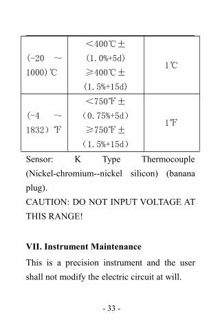
Range Accuracy Resolution
- 33 -
(-20 ~
1000)℃
<400℃±
(1.0%+5d)
≥400℃±
(1.5%+15d)
1℃
(-4 ~
1832)℉
<750℉±
(0.75%+5d)
≥750℉±
(1.5%+15d)
1℉
Sensor: K Type Thermocouple(Nickel-chromium--nickel silicon) (bananaplug).CAUTION: DO NOT INPUT VOLTAGE ATTHIS RANGE!
VII. Instrument Maintenance
This is a precision instrument and the usershall not modify the electric circuit at will.
- 34 -
1. Keep the instrument away from water, dustand shock.
2. Do not store and operate the meter underthe condition of high temperature, highhumidity, combustible, explosiveenvironment and strong magnetic field.
3. Wipe the case with a damp cloth anddetergent; do not use abrasives andalcohol.
4. If the instrument is not operated for a longtime, please take out the battery to avoidleakage.
5. Pay attention to the status of the 1.5vbattery. When the LCD displays a flashing“ ”symbol, the battery shall bereplaced;
The steps are as follows:

- 35 -
5-1. Loosen the screw on the back coverthat secures the battery door and exitthe battery door;
5-2. Remove 1.5V batteries and replacethem with two new ones. Although a1.5V battery of any standard can beused, but in order to extend theoperation life, alkaline batteries shouldbe used;
5-3. Close the battery door and secure thescrew.
Precaution:1. Don’t input voltage higher than DC 1000V
or AC Peak Value.2. Don’t measure voltage at current,
resistance, diode and buzzer range.
- 36 -
3. Don’t use the instrument when the batteryhas not been installed properly or the backcover has not been tightened.
4. Prior to the replacement of battery or fuse,please remove the test leads from themeasuring points and switch off the meter.
VIII. Fault Elimination
If the instrument could not workproperly, please try the following tips to solvesome general problems. If the problems stillexist, please contact the maintenance centeror the distributor. If the problems still exist,please contact our customer service team [email protected].

- 37 -
Fault Solution
No Display● Turn on power;● Replace battery.
symbolappearance
● Replace battery.
Inaccuratemeasuringvalues
● Replace battery.
This Instruction is subjected to changewithout any further notice.
The content of this Instruction isconsidered correct, and in case readers findany errors and missing parts, please contactthe manufacturer.
The Company shall not be held liablefor any accidents and hazards resulted fromthe mal-operations by the user.

- 38 -
The function elaborated by thisInstruction shall not be taken as the reasonsfor using the product for special purposes.