direct plasma interaction with living tissue · 2014-09-05 · iii abstract direct plasma...
TRANSCRIPT

Direct Plasma Interaction
with Living Tissue
A Thesis
Submitted to the Faculty
of
Drexel University
by
Gregory Fridman
in partial fulfillment of the
requirements for the degree
of
Doctor of Philosophy
September 2008
© Copyright 2008
Gregory Fridman. All Rights Reserved

ii
ACKNOWLEDGEMENTS
I would like to sincerely thank my thesis advisors for all their help throughout the time of
my doctoral studies. My colleagues, coworkers, and friends were also an integral part of
my development and without the help of all who surround me I would have never been
able to complete this work.
I would especially like to thank all the people at Drexel University’s School of Biomedical
Engineering, College of Engineering, College of Medicine, Drexel’s Machine Shop staff,
University of Pennsylvania’s Micro-Fabrication Facility staff, and UPenn School of
Veterinary Medicine. Much appreciated is the valuable advice from the members of Drexel
University’s Institutional Animal Care and Use Committee (IACUC), Institutional Review
Board (IRB), representatives of the Food and Drug Administration (FDA), Drexel’s office
of Technology Commercialization, Knoble Yoshida & Dunleavy LLC, and Woodcock
Washburn LLP.
Finally, I would like to acknowledge the financial support this work received from the Ben
Franklin Technology Partners, Wallace H. Coulter Foundation, National Science
Foundation (NSF), Defense Advanced Research Projects Agency (DARPA), and Bayshore
Holdings LLC.

iii
ABSTRACT
Direct Plasma Interaction with Living Tissue Gregory Fridman
Dr. Gary Friedman, Dr. Kenneth Barbee
For some time, plasma has been used in medicine to cauterize or cut tissue using heat
and mechanical energy. In the recent decade, some researchers around the world
have started to investigate how gas jets that pass through thermal plasma can be
employed in medicine. This thesis presents the first investigation of biomedical uses
of non‐thermal plasma discharge which comes in direct contact with living tissue. It is
demonstrated that the direct application of non‐thermal plasma in air can cause rapid
deactivation of bacteria on surfaces of tissues without causing any visible tissue
damage. Medical need for such a device is discussed. Construction and operation of
various types of non‐thermal plasma power supplies and many types of treatment
electrodes are presented as well. Application of this plasma to living organisms is
shown to be safe from both the electrical perspective and from the biological
perspective. Biological safety is revealed through a series of differential skin toxicity
trials on human cadaver tissue, live hairless mouse skin tissue, live pig skin tissue,
and finally in an open wound model on pigs. Direct non‐thermal plasma in air is
shown to deactivate bacteria about 100 times faster than indirect application using
jets. A series of experiments reveal that this effectiveness is due to the ability of direct
discharge to bring charges to tissue surfaces. It is demonstrated that neither
ultraviolet (UV) radiation nor neutral active species such as hydroxyl radicals or
ozone produced in plasma are responsible for the main effect on bacteria. Although

iv
much additional work remains on establishing detailed mechanism by which charges
from plasma achieve this effect, the work carried out in this thesis clearly
demonstrates that direct application of non‐thermal plasma in air can be a very useful
tool in medicine.

v
CONTENTS
Acknowledgements ii
Abstract iii
List of Figures viii
List of Tables xv
Chapter 1. Direct Non-Thermal Plasma Medicine versus Conventional Thermal and Jet
Plasma Treatment of Living Tissue 1
1.1. Sterilization of Non-Living Objects for Medical Applications: a Review 5
1.2. Plasma-Assisted Wound Healing and Tissue Regeneration: Discharge Systems for
Air-Plasma Surgery and Nitrogen Oxide (NO) Therapy 9
1.3. Non-Thermal Plasma Treatment of Various Diseases 14
1.3.1. Non-Equilibrium Pulsed Spark Plasma Jet 14
1.3.2. Non-Equilibrium “Plasma Needle” Treatment 17
1.3.3. Indirect 6-Electrode Thermal Microwave Plasma Torch System 19
1.4. Review Summary of Non-Equilibrium Plasma Applications in Medicine 21
Chapter 2. Device for Direct Non-Damaging Application of Plasma to Living Tissue:
Floating Electrode Dielectric Barrier Discharge (FE-DBD) 23
2.1. Principle of Operation of the Floating Electrode Dielectric Barrier Discharge. 24
2.2. Application of FE-DBD Plasma to Biological Objects 26
vi
2.3. Observation of the FE-DBD Plasma 28
Chapter 3. Direct Non-Equilibrium Plasma Application for Skin Sterilization;
Effectiveness of Direct versus Indirect (Jet) Plasma Treatment 31
3.1. Quantitative Direct Sterilization on Agar 31
3.2. Comparison of Direct and Indirect Sterilization in Open Air 34
3.2.1. Direct and Indirect Plasma Setup Employing Mesh to Separate the Effect 38
3.2.2. Direct and Indirect Plasma Setup Employing Gas Flow (Blower) to Separate the
Effect 41
3.2.3. Results of Direct and Indirect Treatment in Ambient Air 42
3.3. Effects of UV Radiation, Applied Electric Field, Thermal Energy, and Other
Indirect Plasma Effects 50
3.4. Direct and Indirect Plasma Treatment in Various Gases 54
3.5. Effect of Localized High Electric Fields and Effect of Heating 56
3.6. Summary of Direct with Indirect comparison of FE-DBD Plasma Application to
Tissue 65
Chapter 4. Direct Non-Damaging Treatment by Non-Equilibrium Plasma of Living Tissue:
Toxicity Trials 67
4.1. Skin Toxicity Trials on Human Cadaver Tissue 69
4.2. Skin Toxicity Trials on Live Hairless Mice 72
4.3. Skin Toxicity Trials on Live Regular Swine 78
vii
4.4. Wound Toxicity Trials on Live Regular Swine 83
4.5. FE-DBD Treatment of Living Tissue: Next Steps 90
Concluding Remarks 95
List of References 97
Vita 119

viii
LIST OF FIGURES
Figure 1. Photograph of the Floating Electrode Dielectric Barrier Discharge (FE-DBD)
plasma in direct contact with living tissue. ............................................................................ 3
Figure 2. A principal schematic of the plasma needle setup [18]. ....................................... 18
Figure 3. A void created in a cell culture, grown on a Petri dish. At the incidence of the
plasma needle, the cells are removed (suspended in the medium and washed away) [18]. . 19
Figure 4. Microwave plasma torch schematic (left) and plasma output photo (right) [105].
.............................................................................................................................................. 20
Figure 5. Bacterial cultures on agar plates after 2 minutes of plasma treatment. Left:
methicillin-resistant Staphyolococcus aureus (gram positive) Right: Burkholderia cepacia
(gram negative) [104]. .......................................................................................................... 21
Figure 6. Histological images of skin samples, treated ex-vivo. After 2 minutes no changes
could be observed with respect to the untreated control sample. Vacuolization of
keratinocytes can be observed after 10 minutes [104]. ........................................................ 21
Figure 7. Simplified electrical schematic of a) electrode itself, b) electrode near the treated
object, and c) plasma discharge on the treated object. ......................................................... 25
Figure 8. General schematic of the plasma treatment experimental setup. .......................... 27
Figure 9. Principal schematic of the FE-DBD treatment setup with removable meshes and
windows. In this setup either agar with bacteria (shown), cell culture, or living tissue can
be treated. ............................................................................................................................. 28
Figure 10. Side view of plasma over the surface of water at different exposure times. ...... 29

ix
Figure 11. Water electrode setup schematic. ....................................................................... 30
Figure 12. 0.004 sec (left) and 0.2 sec (right) exposures of the FE-DBD plasma in dry air
(from gas tank) at 3 slpm flow rate with sinusoidal excitation wave. .................................. 30
Figure 13. Photograph of the blood agar Petri dish following 24 hour incubation period of
bacterial sample treated by FE-DBD plasma for 10 seconds: plasma-agar contact area is
completely clean of bacterial colonies, area outside of plasma shows partial inactivation,
and the rest of the Petri dish shows complete coverage with bacterial colonies. ................. 34
Figure 14. A 3-dimentioan representation and schematic of the electrode with controlled
atmosphere. .......................................................................................................................... 39
Figure 15. Schematic of treatment of bacteria on blood agar and the electrode footprint
generated by this method. .................................................................................................... 39
Figure 16. Schematic of the direct/indirect treatment setup in the “direct” mode without the
grounded mesh: plasma contacts bacteria directly. .............................................................. 40
Figure 17. Schematic of the direct/indirect treatment setup in the “indirect” mode with the
grounded mesh: plasma is bound by the mesh and only the plasma afterglow can reach the
surface of bacteria. ............................................................................................................... 41
Figure 18. Schematic of the direct/indirect treatment setup with blower used to create the
indirect treatment effect of the plasma afterglow. ............................................................... 42
Figure 19. Photograph of the setup used for direct/indirect experiment with using the
blower to move air through plasma. ..................................................................................... 42
Figure 20. Using a blower to shift sterilization region does not affect plasma and shows
little effect of the afterglow: 15 seconds of treatment with (a) blower off and (b) blower on

x
(air flows up). Note: arrow is painted on the back of the dish and shows through on the
photograph. .......................................................................................................................... 46
Figure 21. Zoomed in photograph of the bacterial growth results following plasma
treatment and incubation (photograph is converted to black and white for increased
contrast). Note: arrow is painted on the back of the dish and shows through on the
photograph. .......................................................................................................................... 46
Figure 22. Results of measurement of light intensity in the visible spectrum for no mesh,
fine mesh, and coarse mesh. ................................................................................................. 48
Figure 23. Results of measurement of light intensity in the ultraviolet spectrum measured
at three peaks (239.5 nm, 263.54 nm, and 284.03 nm) without mesh (taken as 100%) and
with mesh. ............................................................................................................................ 49
Figure 24. Direct application of plasma yields to better sterilization efficiency than
treatment by plasma afterglow: (a) 5 seconds and (b) 15 seconds of direct plasma
compared with (c) 30 seconds and (d) 2 minutes of plasma jet. .......................................... 50
Figure 25. Emission from DBD plasma over the cell surface in UV range. ........................ 51
Figure 26. No effect on bacteria protected from plasma by MgF2 slide (10 mm square in
the center) is observed. ......................................................................................................... 52
Figure 27. Grounded mesh placed directly on bacteria (no space) generates interesting
pattern: only mesh openings are sterilized (magnified area is color-corrected for clarity). 53
Figure 28. Identification of different areas under the FE-DBD electrode following the
plasma treatment and 24-hour incubation: (1) under the electrode, (2) outside of the
electrode but inside of the treatment area bound by legs, (3) inside of the gas channel, (4)
xi
immediately outside of the gas channel, and (5) outer parts of the dish not in the direct gas
path. ...................................................................................................................................... 55
Figure 29. Avalanche transition to streamer [162]. ............................................................. 57
Figure 30. Rotational and vibrational temperature measurements from a model fit to 2nd
positive Nitrogen system; please note, “modeled data” curve was intentionally raised,
otherwise it is invisible since the curve-fit is nearly perfect. ............................................... 60
Figure 31. Photograph of plasma through water electrode. 1/3 second (0.33 sec) shutter
open time. ............................................................................................................................. 60
Figure 32. Photograph of plasma through water electrode. 1/320 second (0.0031 sec)
shutter open time. ................................................................................................................. 61
Figure 33. Oscillogram of the nanosecond pulse voltage and current. Voltage rises to ~ 30
kV in ~ 10 ns, or 3,000 V/ns. ............................................................................................... 63
Figure 34. Diagram of a setup to capture a single pulse of Dielectric Barrier Discharge
plasma on photographic film. ............................................................................................... 63
Figure 35. Image produced on black and white photographic film (100 ISO sensitivity
negative film) by a single nanosecond pulse of DBD plasma. ............................................ 64
Figure 36. Image produced on black and white photographic film (100 ISO sensitivity
negative film) by a single microsecond pulse of DBD plasma. ........................................... 65
Figure 37. Photograph of the FE-DBD treatment electrode with a “jacket” which allows for
control of distance between electrode and treatment target. ................................................ 69

xii
Figure 38. Photographs and schematics of the results of 2 minutes of FE-DBD plasma
treatment at 1.6 W/cm2. Skin is laying on metal surface which leads to uncontrollable
results: uniform treatment is some cases (top) and non-uniform in others (bottom). .......... 70
Figure 39. Schematic of the tissue treatment setup with vacuum suction and zoom
photographs of the vacuum holder perforations. .................................................................. 70
Figure 40. Vacuum suction treatment setup in operation during plasma treatment. ............ 71
Figure 41. Photos (top) and tissue histology (bottom) of cadaver skin samples after FE-
DBD treatment: control (left), 15 seconds of treatment (center), and 5 minutes of treatment
(right) – no visible damage is detected. ............................................................................... 72
Figure 42. Photograph of a regular mouse during hair shaving procedure. Post shaving the
skin appears to be quite irritated and thus the model is not usable for a skin toxicity trial. 73
Figure 43. Photograph of a Charles River Laboratories SKH1 hairless mouse immediately
after arrival at the animal care facility. ................................................................................ 74
Figure 44. Photograph of two power supplies (microsecond pulsed and continuous
sinusoidal) with the small 10 mm diameter electrode for treatment of mouse skin. ........... 75
Figure 45. Schematic of the 10 mm diameter copper electrode with attached perforated
spacer for controlled treatment of a mouse. ......................................................................... 75
Figure 46. Photograph of an animal immediately following treatment. The perforated
spacer is left on the area of treatment to mark it for later sample harvesting. Areas 1 and 2
have already been treated, in this particular case for 75 seconds at 0.3 Watt/cm2 surface
power density by microsecond pulsed power supply. No damage to skin is observed
visually. ................................................................................................................................ 76

xiii
Figure 47. Histology of toxic and non-toxic to SKH1 skin plasma doses, compared to
untreated skin. ...................................................................................................................... 77
Figure 48. Animal remains fine immediately after a high plasma dose (more than 10 times
higher than needed for skin sterilization). ............................................................................ 77
Figure 49. Animal remains fine two weeks following a high plasma dose (more than 10
times higher than needed for skin sterilization). .................................................................. 78
Figure 50. 3D schematic of the electrode used for swine skin experiments. ....................... 79
Figure 51. Photograph of the modified FE-DBD electrode attached to animal skin using
tape. ...................................................................................................................................... 80
Figure 52. Photograph of the animal skin prior (left) and immediately following a 10-
minute FE-DBD treatment at low frequency Setting #1 (right). A mild skin inflammation is
visible immediately after the treatment (shown) which disappears within a few minutes
following the treatment (not shown). Black markings on the skin indicate position of the
edge of the treatment electrode (for skin sample harvesting purposes). .............................. 81
Figure 53. H&E histological stain of the skin sample treated for 10 minutes at low
frequency Setting #1 (Figure 52). No microscopic damage to skin can be seen. ................ 82
Figure 54. Photograph of the animal skin immediately following treatment by Bovie®
knife (positive control) – excessive skin damage, desiccation, and inflammation are clearly
visible. .................................................................................................................................. 83
Figure 55. Photograph of a process of making a partial thickness skin wound with a
dermatome knife (left) and a zoomed in photograph of the resulting wound immediately
prior to the FE-DBD plasma treatment. ............................................................................... 85

xiv
Figure 56. Photograph of a positive control treatment with Bovie® knife (left) where the
tissue is clearly desiccated and blood is clotted but the tissue damage is quite extensive.
Compared to a photograph of a wound treated by FE-DBD plasma for 15 minutes in low
power Setting #1 (right) where no significant tissue damage is observed and a layer of
coagulated blood is formed over the wound surface. ........................................................... 86
Figure 57. Results of H&E histological stain for samples described in Table 6. ................ 88
Figure 58. Results of H&E histological stain for samples described in Table 7. ................ 90

xv
LIST OF TABLES
Table 1. Dependence of the current density and ion concentration of the Xenon plasma
flow on the distance [22]. ..................................................................................................... 15
Table 2. Results of Staphylococcus inactivation by air plasma [22]. .................................. 15
Table 3. Bacteria sterilization results (in cfu/mL) ............................................................... 32
Table 4. Results of treatment of bacteria by FE-DBD plasma in different gases. Areas of
treatment are identified in Figure 28. Note: all experiments are repeated in triplicate and
the results presented here are averaged. ............................................................................... 55
Table 5. Plasma power supply settings used in the swine skin treatment experiments. ...... 80
Table 6. Results and analysis of FE-DBD plasma treatment of wound surface. ................. 86
Table 7. Results and analysis of FE-DBD plasma treatment of wound surface. ................. 88

1
CHAPTER 1. DIRECT NON-THERMAL PLASMA MEDICINE VERSUS CONVENTIONAL THERMAL AND JET PLASMA
TREATMENT OF LIVING TISSUE
In physical sciences, “plasma” refers to the forth state of matter; while in medicine and
biology “plasma” is mostly known as the non-cellular fluid component of blood.
Interestingly, the term plasma has been coined by Irving Langmuir to emphasize that the
characteristics of ionic liquids ubiquitous in biology and medicine are analogous to those
of ionized gas [1]. Despite this historical connection, few applications of plasma in
medicine have been explored until recently [2]. This situation is rapidly changing, and in
this thesis we will discuss a new non-thermal atmospheric pressure plasma system which
can effectively inactivate bacteria on human tissue without damaging it.
Plasma can exist in a variety of forms and can be created in different ways. In many
technological applications, for example, plasma exists at low gas pressures. Lightning, on
the other hand, is an example of atmospheric pressure thermal plasma. For the purpose of
this work it is important to distinguish between thermal and non-thermal plasma. In all
plasmas supported by electric field, electrons receive the external energy much faster than
much heavier ions. Electrons have the opportunity to heat up to several thousands of
degrees before their environment heats up. In non-thermal plasma, cooling of ions and
uncharged molecules can be highly effective compared with the energy transfer from
electrons. As a result, gas remains at low temperature. Since electrons and gas are at very
different temperatures, non-thermal plasma is also called non-equilibrium plasma. In
thermal plasma, on the other hand, energy flux from electrons to heavy particles

2
equilibrates the energy flux from heavy particles to the environment only when
temperature of heavy particles becomes almost equal to the electron temperature. Of
course the terms thermal and non-thermal, equilibrium and non-equilibrium are not very
precise. Sometimes even a few tens of degrees difference in the temperature of the heavier
species can play a substantial role. This is particularly important when various plasma-
chemical processes are considered. It is certainly important when plasma is used to treat
heat sensitive objects.
Some of the earlier applications of plasma in medicine relied mainly on the thermal effects
of plasma. Heat and high temperature have been exploited in medicine for a long time for
the purpose of tissue removal, sterilization and cauterization (cessation of bleeding) [3].
Warriors have cauterized wounds by bringing them in contact with red hot metal objects
since ancient times. Electrocautery is a more modern technique which applies controlled
heat to surface layers of tissue by passing sufficiently high current through it [4]. However,
contact of tissue with metal surface of a cautery device often results in adhesion of charred
tissue to the metal. Subsequent removal of the metal can peel the charred tissue away re-
starting bleeding. Some of the earlier applications of plasma in medicine provided an
alternative to metal contact electrocautery. In argon plasma coagulation (APC, also
sometimes called argon beam coagulation) highly conductive plasma replaced the metal
contacts in order to pass current through tissue avoiding the difficulties with tissue
adhesion. Hot plasma is also being employed to cut tissue [3, 5-8], although the exact
mechanism by which this cutting occurs remains unclear. Heat delivered by plasma has
also been employed recently for cosmetic re-structuring of tissue [9-11].

3
What differentiates more recent research on applications of plasma in medicine is the
exploitation of non-thermal effects. Why are non-thermal effects of plasma so interesting
and promising? The main reason is that non-thermal plasma effects can be tuned for
various sub-lethal purposes such as genetic transfection [12-14], cell detachment [15-18],
wound healing [19-23], and others (i.e., [2, 24, 25]). Moreover, non-thermal effects can be
selective in achieving a desired result for some living matter, while having little effect on
the surrounding tissue (Figure 1). This is the case, for example, with recent plasma blood
coagulation and bacteria deactivation which does not cause toxicity in the surrounding
living tissue [19, 20].
Figure 1. Photograph of the Floating Electrode Dielectric Barrier Discharge (FE-DBD) plasma in direct contact with living tissue.
Most of research focusing on the use of non-thermal plasma effects in medicine can be fit
into two major categories: that are direct plasma treatment and indirect plasma treatment.
Direct plasma treatment has been pioneered at Drexel University (see Fridman, Shekhter,

4
Vasilets, et al, 2008 [26]). In direct plasma treatment living tissue or organs play the role of
one of the plasma electrodes. Voltage does not need to be directly connected to this living
tissue electrode, but some current may flow through living tissue in the form of either a
small conduction current, displacement current or both. Conduction current should be
limited in order to avoid any thermal effects or electrical stimulation of the muscles. Direct
plasma treatment may permit a flux of various active uncharged species of atoms and
molecules as well as UV radiation to the surface of the living tissue. These active
uncharged species generated in plasma will typically include ozone (O3), NO, OH radicals,
etc. However, the most important distinguishing feature of the direct plasma treatment is
that a significant flux of charges reaches the surface of the living tissue. These charges may
consist of both electrons as well as positive and negative ions.
In contrast, indirect plasma treatment employs mostly uncharged atoms and molecules that
are generated in plasma, but involves small, if any, flux of charges to the surface. In
indirect treatment the active uncharged species are typically delivered to the surface via
flow of gas through a plasma region.
Both indirect and direct non-thermal plasma treatments permit some degree of tuning of
the plasma properties [27]. For example, the amount of NO vs. ozone produced in plasma
can be tuned. It is also possible to tune micro-structure of the plasma discharge which can
be particularly relevant in direct treatment. The fact that direct plasma treatment involves
substantial charge flux provides greater flexibility in tuning the non-thermal plasma
effects. Indirect plasma treatment, on the other hand, may have an advantage when the
plasma device needs to be at a substantial distance from the surface.
5
In this chapter we will discuss current status of various plasma systems from many
research groups around the world in their applications to medicine. The mode of operation
of these plasmas will be specifically pointed out: is the plasma thermal or not, how is it
generated, and what are some of the benefits and drawbacks.
1.1. Sterilization of Non-Living Objects for Medical Applications: a Review
Traditionally, sterilization or treatment of non-living objects like metals, plastics, fabrics,
and other surfaces have been carried out either by temperature (i.e., autoclaves [28-31]),
liquid or gaseous chemistry (i.e., by ethylene oxide [32, 33], ozone [34, 35], chlorine [36,
37], etc.), or at reduced pressure by non-equilibrium plasmas [38, 39]. Details of such
approaches are widely available in literature. Here we will focus on medical application of
non-equilibrium plasma at atmospheric pressure and surface sterilization of materials
cannot then be overlooked because, after all, these materials later come in contact with
living tissue either as implants, dressings, tools, etc.
Drs. Alexeff and Laroussi and their colleagues reported a rather interesting modification of
a conventional dielectric barrier discharge – a Resistive Barrier Discharge (RDB) [2, 40,
41]. Main feature of the RDB is that is can function in both DC and AC modes, and rather
than a dielectric a wetted high resistivity material is used. RDB has been shown to be
effective in sterilization of E. coli, B. subtilis, and other organisms [2, 41, 42] without
significant damage to the surface being processed. Going back to a more traditional DBD
system, Laroussi and his colleagues [43-46] show that a barrier discharge in helium with

6
small additions of oxygen is not only able to sterilize bacteria but is able to influence
metabolic changes in the organisms surviving the treatment [44]. This raises an intriguing
question – can plasma-resistant bacteria emerge? Due to synergetic effect of plasma
constituents on bacteria, plasma-resistance might not be possible or statistically probable,
however, the authors think that this issue might become rather important in the near future
and should be addressed. Two more discharges are studied by Dr. Laroussi and colleagues:
plasma plume (a helium jet) [47, 48], and an arc-like discharge between metal and water in
air [49, 50]. Both discharges are also reported to efficiently inactivate various micro-
organisms.
Dr. Massines and her colleagues propose a DBD discharge in N2/N2O mixture for micro-
organism inactivation (i.e., B. subtilis spores) [51-53]. Operated at atmospheric pressure,
her results indicate a very high dependence of the inactivation efficiency on UV, which is
somewhat contrary to results presented by other groups [51]. In fact, the difference is
attributed to the fact that the gas composition necessary to achieve the best results is in a
very narrow concentration range of the oxidant molecule, which might have simply been
overlooked previously. Though this study offers good information on UV, a real-life
environment might need a system that is slightly less picky as to the gas mixture
concentration ranges. However, one needs to account for effects of ultraviolet radiation on
bacteria as apparently they cannot be neglected, even in plasmas where doses of UV are
lower than in that proposed by Dr. Massines [51].
Microplasmas have recently been gaining momentum in bio-medical applications. These
systems of 10-500 µm characteristic dimensions capable of generating diffuse atmospheric

7
pressure plasmas offer an interesting solution in, for example, medical diagnostics and
environmental sensing. Dr. Becker and colleagues [54, 55] offer a few different
microplasma sources suitable for remediation of gaseous waste streams, removal of
volatile organic compounds (VOCs), detection of trace contaminants in gas flow,
generation of high intensity ultraviolet (UV) radiation, and sources suitable for micro-sized
plasma-reactors. Though the temperature of these discharges can be at or near room
temperature in noble gases, when a molecular gas (i.e., air) is used plasma temperatures
can be high, on the order of 2,000 K. Dr. Becker et al. show efficient inactivation of B.
subtilis spores (1 log reduction in ~100 seconds) and B. stearothermophilus spores (1 log
reduction in ~90 seconds) without damage to the substrate; more interestingly they are able
to inactivate bio-films of Chromobacterium violaceum CV026 achieving 2 log reduction in
~ 5 minutes and 3 log reduction in ~60 minutes of plasma afterglow treatment [54]. In
general, these microplasmas have not yet found a niche in medicine directly through many
potential applications are clearly possible and the reader is encouraged to take a look at a
review of the recent developments in that field [55].
Dr. Roth and his colleagues have developed a one atmosphere uniform glow discharge
plasma (OAUGDP) system capable of addressing a broad range of potential applications
[56-62]. OAUGDP is a DBD-like bipolar RF plasma discharge operated in air or other
gases. The list of potential applications where experimental evidence is very favorable
includes increasing surface energy and wettability of fabrics, films, and solid surfaces;
sterilization of various surfaces for healthcare and food processing; decontamination of
surfaces compromised by chemical or biological warfare agents; a sterilizable air filter to

8
deal with the sick building syndrome [63]; removal of soot and volatile organic compounds
from Diesel engine exhaust; mercury-free atmospheric pressure fluorescent lamps;
stripping of photoresist and directional etching in microelectronics; plasma assisted
chemical vapor deposition; and plasma aerodynamic flow control. For details on these
applications reader is encourages to consult a recent publication by Dr. Roth et al. [60]. Of
note, however, is a less recent publication from Dr. Roth’s group comparing sterilization
efficiency of their system against a multitude of bacteria, yeasts, and viruses [57]. D-
values, or time to 90% reduction in micro-organism load, are ranging from 6 seconds for
E. coli bacteria to 6.8 minutes for Bacteriophage Phi X 174 virus. Additionally
survivability of these organisms on different substrates is addressed comparing glass, agar,
and polypropylene with the later showing highest survival times. In general, OAUGDP
was not reported to be used in medicine directly; however, sterilization of medical
instruments and other surfaces found in the hospital as well as air sterilization in an
operating room is on the list of potential medical applications [60].
Dr. Kong and his colleagues have investigated inactivation of various organisms by pulsed
electric field [64], and, primarily, by He/O2 RF plasma afterglow (or jet) [65-74]. Ability
of their plasma setup to inactivate B. subtilis spores [65, 69] and various E. coli mutants
[70] does not come as a surprise, however the results on inactivation of biofilm-forming
bacteria are quite intriguing. Dr. Vleugels et al. [72] have successfully achieved
inactivation of biofilm-forming Pantoea agglomerans in sterilization of foods, specifically
of bell peppers (Capsicum annuum). He/O2 plasma afterglow was shown to effectively
inactivate the biofilm without causing unacceptable levels of discoloration to the peppers

9
[72]. Detailed analysis of this system reveals that the primary role in inactivation is played
by reactive oxygen species (e.g. atomic oxygen and OH) with minor aid from UV photons,
charged particles, heat, and electric fields [65, 68, 70, 71, 73, 74]. Another interesting idea
is not only sterilization of various surfaces but complete decontamination of them with
removal not only of bacterial load but of the remaining protein debris. Deng et al. show
that this RF plasma jet treatment can effectively remove proteins from surface of medical
instruments, achieving up to 4.5 log reduction [66, 67]; here, again, reactive oxygen
species are deemed to be the major inactivation factors.
1.2. Plasma-Assisted Wound Healing and Tissue Regeneration: Discharge Systems for
Air-Plasma Surgery and Nitrogen Oxide (NO) Therapy
Effective use of hot plasma in surgery has been first demonstrated in 1960s: plasma
afterglow jet of an inert gas has been applied for tissue sectioning with instant blood
coagulation. Because of that plasma-surgical devices got a long-standing name of “plasma
scalpel” in the hospitals (see, for example, Glover et al. [75]). An example plasma of a
thermal plasma used in surgery for wound healing and tissue regeneration is the “Plazon”
system based on the jet of hot air plasma rapidly quenched which provides relatively high
NO concentration with significant therapeutic effect [76, 77]. This plasma device is used in
two modes. In the first “hot mode” plasma jet is used for rapid coagulation and sterilization
of wound surfaces, destruction and desiccation of dead tissue and pathologic growths,
dissection of biological tissues. In the second “cold mode” NO-containing plasma gas flow

10
with temperature of 20 to 40°C is used for stimulation of regenerative processes and
wound healing.
The “Plazon” generators [21, 76, 77] are the DC arcs with different configurations of the
exit channels corresponding to the different applications (blood coagulation, tissue
destruction, therapeutic manipulation/stimulation). Main and common elements of the
system construction are the liquid-cooled cathode, intra-electrode insert, and anode.
Atmospheric air enters the manipulator through the built-in micro-compressor, passes
through the plasma arc, heats up and thus accelerates, and exits through the hole in the
anode of the plasma-generating module. Plasma temperature at the anode exit differs in
different configurations of the device, corresponding to different medical applications.
Further away from the anode, temperature drops rapidly, and at 30-50 mm from the anode,
the flow is composed simply of the warm gas, and the plasma-generated NO. Nitrogen
oxide content in the gas flow is mainly determined by the quenching rate. The necessary
quenching rate for effective operation of the medical device is about ~107-108 K/sec.
Commonly, the cooling rate of plasma jets is on the order of ~106 K/sec. Thus, to achieve
the cooling rate of ~107-108 K/sec, it is necessary to utilize additional cooling of the
plasma jet, which has been achieved by special construction of the plasma nozzles.
The therapeutic manipulator-stimulator configuration of the “Plazon” discharge system is
used solely for therapeutic treatment by exogenic nitrogen oxide. The principle difference
of this manipulator is that the air-plasma jet does not freely exit into the atmosphere, but
rather it exits the anode into the two-step cooling system, gas channels of which are created
in a maze scheme to force-cool the jet by the liquid circulating from the cooling system.

11
This construction allows one to obtain NO-containing gas flow (NO-CGF) with
sufficiently low temperature, and optimal concentration of nitrogen oxide molecules,
which makes it possible to apply this manipulator for treatment of external body surfaces
by using the cooling hose of 150 mm length (temperature of NO-CGF at the exit ~36 °C).
Of course, NO content in the gas flow depends on the distance from the exit channel.
Additionally, for laparoscopic operation, a special manipulator of 350 mm length and 10
mm diameter is utilized.
The possible operating regimes of the apparatus are defined by the characteristics of the
gas flow exiting from the manipulator, main parameters of which are its temperature and
the nitrogen oxide content. First group of regimes – regimes of free-flowing plasma off-gas
exiting the manipulator; second group of regimes – regimes of treatment of bio-tissues by
completely cooled (20ºC) NO-containing gas flow, to obtain which a manipulator is
connected to the internal gas cooler, and delivery of NO-CGF to bio-tissues is achieved
through a silicone tube with an attached tip of 130 or 390 mm length, and the exit channel
diameter of 0.7 mm. This allows not only direct treatment of the bio-tissues by NO, but
also its delivery to a pathologic center through drainage tubes, puncture needles, or any
endoscopic devices (gastroscope, broncoscope, cystoscope, rectascope, etc).
The Nobel Prize in medicine and biology was awarded in 1998 to R. F. Furchgott, L. J.
Ignarro, and F. Murad for their work in investigation of function of nitrogen oxide as a
signal molecule [78]. Today it is well known that in a human organism, NO serves a
multitude of essential biological functions – it regulates blood vessel tone (via relaxation of
flat epithelial cells) and blood coagulation, immune system and early apoptosis, neural

12
communication and memory, relaxation of flat bronchial and gastrointestinal muscles,
hormonal and sex functions, NO offers antimicrobial and antitumor defense, etc. In
pathology, NO plays a major role in adaptation, stress, tumor growth, immunodeficiency,
cardiovascular, liver, and gastrointestinal tract disease, etc. This explains wide possibilities
of the plasma-generated exogenic NO in multiple medical applications.
Importance of exogenic NO in infection and inflammation processes is also well studied
and is linked with antimicrobial effects; stimulation of macrophages; induction of
cytokines, T-lymphocytes, and many immunoglobulins; interaction with oxygen radicals;
and influence on microcirculation, cytotoxic and cytoprotective role in different conditions.
During inflammation, macrophages and some other cells (i.e. aibroblasts, epithelial cells,
etc.) produce NO via inducible NO-synthase (iNOS) in quantities significantly greater (2
orders of magnitude) than normal when NO is formed via constructional NOS: endothelial
(eNOS) and neuronal (nNOS).
Exogenic NO is also crucial in trauma wound processes. Activity of inducible NO-
synthase (iNOS) grows substantially in trauma wounds, burn wound tissues, bone fracture
site tissues, and others in the inflammatory and proliferation phases of the healing process.
Activation of iNOS was also discovered in cultivation of wound fibroblasts. Macrophage
activation in a wound, cytokine synthesis and proliferation of fibroblasts, epithelization
and wound healing processes are all linked with the activity levels of iNOS. In animal
models, injection of iNOS inhibitors disrupts all of these processes and especially the
synthesis of collagen, while NO synthesis promoters increase the rate of these processes.

13
Animals with iNOS deficiency demonstrate significant decrease in wound healing rate,
however this can be reversed by injection of iNOS gene. In complicated wound models,
for example in experimentally-induced diabetes, protein deficiency, injection of
corticosteroids or immunosuppressants, and also in patients with tropic ulcers, lowered
activity of iNOS is usually discovered which correlates to slowed healing processes.
Exogenic delivery of NO-donors (nitrogen-containing compounds) to the wound promotes
and speeds up healing processes in animals with complicated wounds and in animals with
inhibited iNOS. This knowledge, coupled with theoretical and experimental data on NO
generation in air plasmas, served as a basis for a series of bio-medical experiments focused
on use of the plasma-generated exogenic NO, delivered directly to the pathologic site, for
control of inflammatory processes and increase in the rate of wound healing.
Possibility of directing of the plasma-generated NO-containing gas flows through puncture
needles, vent lines, and endoscopic instruments, and also the inhalation method of action
considerably enlarges prospects for the plasma NO-therapy in treatment of the ulcero-
necrotic, erosive and inflammatory processes in the pleural and abdominal cavities, lungs,
stomach and bowels, ear nose and throat (ENT) organs (purulent sinusitis, purulent otitis
media, paratonsillar abscesses), etc. Effectiveness of the plasma NO-therapy is already at
present shown with a number of diseases in pulmonology [79], phthisiology [80],
traumatology and orthopedics [21, 81], gynecology [82-84], dentistry [85], maxillofacial
surgery [21], ophthalmology [86], otorhinolaryngology [87], dermatology [88],
gastroenterology [89], purulent peritonitis [81], and in other applications discussed in
further detail in our recent review [26].

14
1.3. Non-Thermal Plasma Treatment of Various Diseases
1.3.1. Non-Equilibrium Pulsed Spark Plasma Jet
A special micro-plasma jet system has been developed by our collaborators for local
medical treatment of skin diseases, and especially for treatment of corneal infections (see
Fridman, Shekhter, Vasilets, et al, 2008 [26]). The device allows generation of plasma
flows with average gas temperature not exceeding 30-40°C [22, 26]. It consists of a coaxial
cathode and needle-like anode, which is fixed in metal capillary. The gas is fed through the
capillary to the discharge gap. The anode is connected with the positive lead of the power
source and the cathode is grounded. The discharge appears on the nozzle output if the
pressure on the nozzle input is higher than the atmospheric pressure. The discharge is a
specific plasma sphere with the diameter ~4 mm, atmospheric air or xenon are fed through
the capillary at 0.2-0.5 atm, the discharge voltage is 1-3 kV, the pulse duration is about 50
µs, the total power was kept on the order of 1-2 W.
The medical micro-plasma operated in Xe radiates intensively in the UV range, and
operated in air it generates excited oxygen species, ozone, oxides of nitrogen, and OH
radicals [22]. Both regimes have bactericidal effects and air plasma is able also to aid in
tissue regeneration via the NO-therapy mechanisms discussed above. UV-radiation of Xe
plasma in this case is: UVA (315-400 nm) 180 μW/cm2, UVB (280-315 nm) 180 μW/cm2,
and UVC (200-280 nm) 330 μW/cm2. UV-radiation of air plasma is: UVA (315-400 nm)
53 μW/cm2, UVB (280-315 nm) 25 μW/cm2, and UVC (200-280 nm) 90 μW/cm2. Results

15
of probe measurements of current density, velocity, and ion concentration at different
distances from the exit nozzle are shown in Table 1.
Table 1. Dependence of the current density and ion concentration of the Xenon plasma flow on the distance [22].
Distance, mm 1 1.3 2 3
Current density, mA/cm2 2040 2000 240 60Velocity, cm/sec 2∙104 1.8∙104 1.2∙104 7∙103 Ion concentration, cm‐3 6.4∙1014 3.7∙1014 1.5∙1014 5.3∙1013
Ability of the medical micro-plasma system to sterilize surface has been demonstrated by
Misyn et al. [90-93]. Staphylococcus cultures in liquid media (~2·106 cfu/ml) have been
treated by the air plasma plume of 3 mm diameter, incubated for 24 hours, and counted
(Table 2).
Table 2. Results of Staphylococcus inactivation by air plasma [22].
Culture volume, ml Plasma exposure time, sec
0 (control) 25 50 1001 2∙106 cfu 0 cfu 0 cfu 0 cfu2 4∙106 cfu 25 cfu 0 cfu 0 cfu3 6∙106 cfu 1∙106 cfu 680 cfu 460 cfu
A 6-log reduction in viable bacteria is achieved in 25 seconds of treatment; however the
sterilization efficiency drops off with increasing volume of liquid which inhibits UV
penetration and diffusion of active species generated in plasma. Nevertheless, the micro-
plasma system should be a good solution for treatment of living human and animal skin as
the bacteria are normally at much lower concentrations on skin (<<105 cfu/cm2 of skin
surface [94]).
16
A series of in vitro experiments on bacterial cultures and in vivo experiments on rabbit
eyes [93] affirm the strong bactericidal effect of the micro-discharge with minimal and
reversible changes, if any, in biological tissues, even in such delicate tissues as cornea.
During the investigation of plasma treatment of ulcerous dermatitis of rabbit cornea two
important observations were made: 1) plasma treatment has a pronounced and immediate
bactericidal effect, and 2) the treatment has an effect on wound pathology and the rate of
tissue regeneration and wound healing process.
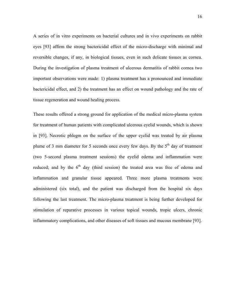
These results offered a strong ground for application of the medical micro-plasma system
for treatment of human patients with complicated ulcerous eyelid wounds, which is shown
in [93]. Necrotic phlegm on the surface of the upper eyelid was treated by air plasma
plume of 3 mm diameter for 5 seconds once every few days. By the 5th day of treatment
(two 5-second plasma treatment sessions) the eyelid edema and inflammation were
reduced; and by the 6th day (third session) the treated area was free of edema and
inflammation and granular tissue appeared. Three more plasma treatments were
administered (six total), and the patient was discharged from the hospital six days
following the last treatment. The micro-plasma treatment is being further developed for
stimulation of reparative processes in various topical wounds, tropic ulcers, chronic
inflammatory complications, and other diseases of soft tissues and mucous membrane [93].
17
1.3.2. Non-Equilibrium “Plasma Needle” Treatment
A radio frequency plasma source, a plasma needle, was recently developed by E. Stoffels
et al. [18, 95-97]. Plasma needle is a flexible hand-held device (Figure 2) consisting of a
0.3 mm diameter needle, 0.8 mm diameter Perspex tube, 10 cm in length. The plasma is
generated at the end of the needle at the applied frequency of 13.56 MHz. This device was
successfully demonstrated in treatment of various cell lines and inactivation of bacteria.
Though the final goal of this plasma treatment is in treatment of dental cavities, localized
and precise inactivation of cancerous tissues, and in other medical applications, at the
moment deeper understanding of biological mechanisms of plasma-cell interaction
mechanisms is being pursued [98]. Dr. Stoffels and her colleagues have thus-far worked
with the following eukaryotic cells and bacteria [18]:
fibroblasts: Chinese hamster ovarian cells (CHO-K1) [99], 3T3 mouse fibroblasts,
muscle cells: rat aortic smooth muscle cells (SMC) (A7r5) [100],
endothelial cells: bovine aortic endothelial cells (BAEC) [100],
epithelial cells: human MR65 cells originating from non-small cell lung carcinoma
(NSCLC) [101],
gram-positive bacteria: Streptococcus mutans,
gram-negative bacteria: Escherichia coli [102, 103], and
artery sections obtained from Swiss mouse (carotid and uterine arteries) [18].

18
Figure 2. A principal schematic of the plasma needle setup [18].
Treatment by plasma needle of various cell lines causes these cells to lift off from the
substrate and float away, without necrosis of these cells (Figure 3) [18]. The penetration
depth of this treatment is usually limited to a single cell layer when no necrosis is observed
while deeper treatment is possible at higher doses where cell necrosis is also observed. In
addition to a well-localized detachment, apoptosis-like behavior was observed in the
detached cells; however, the level of apoptosis appears to be not too significant as about
3% of the human epithelial cells underwent apoptosis while 100% were detached [18]. Dr.
Stoffels hypothesizes that the dosage requirement induction of apoptosis are very narrow
and further investigation onto the biochemical mechanisms of apoptosis induction are
necessary. In treatment of E. coli roughly a 2-log reduction in bacterial load was achieved
in 60 seconds of plasma treatment at 100 mW, 1 cm away from the sample [18, 103].

19
Figure 3. A void created in a cell culture, grown on a Petri dish. At the incidence of the plasma needle, the cells are removed (suspended in the medium and washed away) [18].
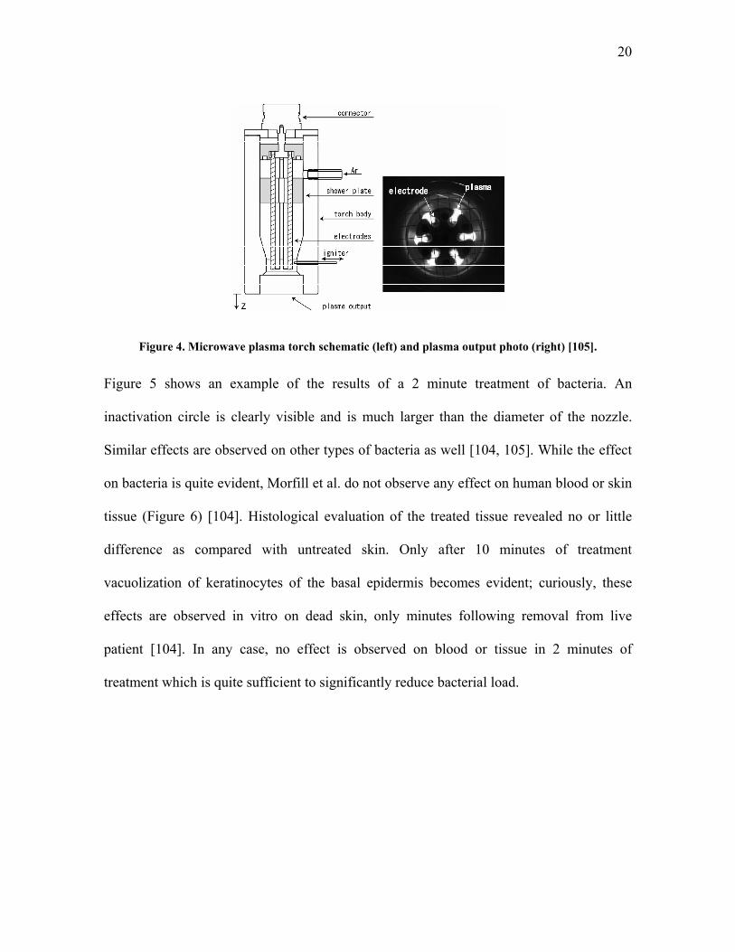
1.3.3. Indirect 6-Electrode Thermal Microwave Plasma Torch System
Treatment of chronic foot and leg ulcers was shown to be possible using a microwave
argon plasma torch which is, as above, rapidly cooled by fast gas flow (Figure 4) [104,
105]. Argon is passed at 3 slpm through a 135 mm tube with six aluminum electrodes to
which 2.45 GHz microwave power is allied. This torch operates at roughly 100 Watt [105].
Interestingly, the plasma afterglow generated in this way is able to sterilize many types of
bacteria in minutes of treatment. Some of the bacteria tested were Staphylococcus
epidermidis, Escherichia coli, Streptococcus pyogenes, Bacillus cereus, Pseudomonas
aeruginosa, etc. Additionally Candida albicans yeast was tested. While the torch was
effective in inactivation on all the organisms tested, the dose requirements and the size of
the inactivation area varied by organism [104].
20
Figure 4. Microwave plasma torch schematic (left) and plasma output photo (right) [105].
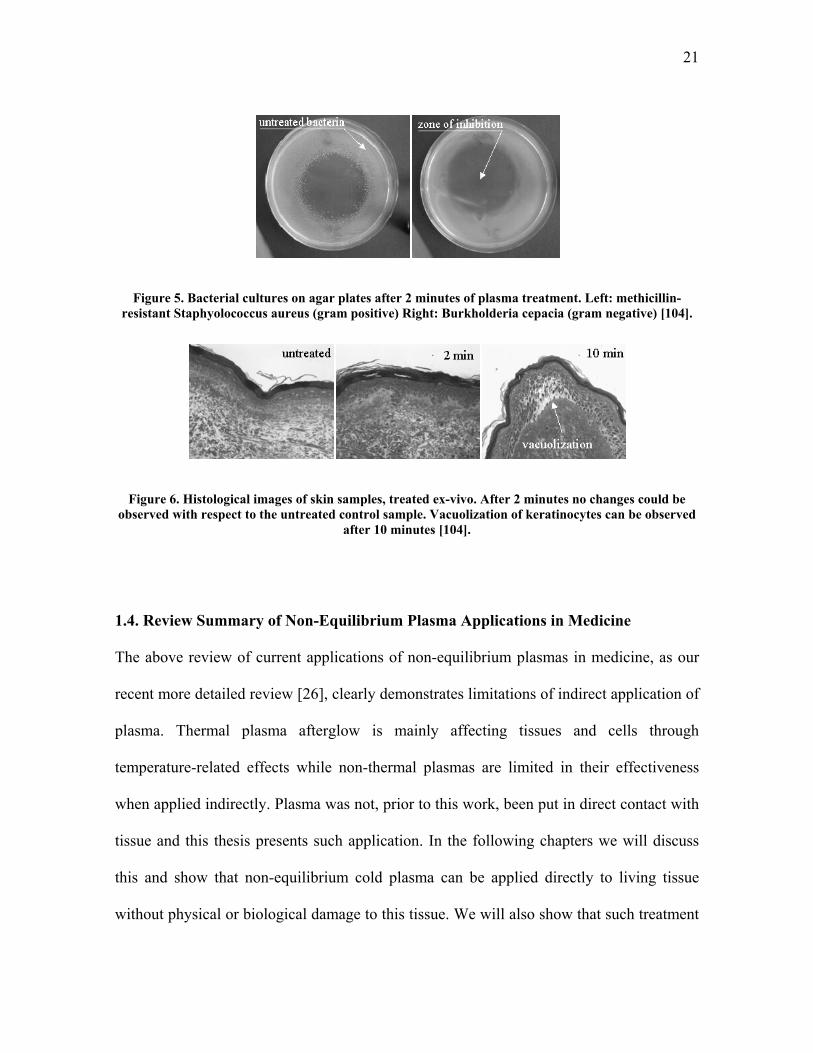
Figure 5 shows an example of the results of a 2 minute treatment of bacteria. An
inactivation circle is clearly visible and is much larger than the diameter of the nozzle.
Similar effects are observed on other types of bacteria as well [104, 105]. While the effect
on bacteria is quite evident, Morfill et al. do not observe any effect on human blood or skin
tissue (Figure 6) [104]. Histological evaluation of the treated tissue revealed no or little
difference as compared with untreated skin. Only after 10 minutes of treatment
vacuolization of keratinocytes of the basal epidermis becomes evident; curiously, these
effects are observed in vitro on dead skin, only minutes following removal from live
patient [104]. In any case, no effect is observed on blood or tissue in 2 minutes of
treatment which is quite sufficient to significantly reduce bacterial load.
21
Figure 5. Bacterial cultures on agar plates after 2 minutes of plasma treatment. Left: methicillin-resistant Staphyolococcus aureus (gram positive) Right: Burkholderia cepacia (gram negative) [104].
Figure 6. Histological images of skin samples, treated ex-vivo. After 2 minutes no changes could be observed with respect to the untreated control sample. Vacuolization of keratinocytes can be observed
after 10 minutes [104].
1.4. Review Summary of Non-Equilibrium Plasma Applications in Medicine
The above review of current applications of non-equilibrium plasmas in medicine, as our
recent more detailed review [26], clearly demonstrates limitations of indirect application of
plasma. Thermal plasma afterglow is mainly affecting tissues and cells through
temperature-related effects while non-thermal plasmas are limited in their effectiveness
when applied indirectly. Plasma was not, prior to this work, been put in direct contact with
tissue and this thesis presents such application. In the following chapters we will discuss
this and show that non-equilibrium cold plasma can be applied directly to living tissue
without physical or biological damage to this tissue. We will also show that such treatment

22
can lead to rapid pathogen inactivation (sterilization) on this tissue at doses far below those
required for damage.

23
CHAPTER 2. DEVICE FOR DIRECT NON-DAMAGING APPLICATION OF PLASMA TO LIVING TISSUE: FLOATING ELECTRODE DIELECTRIC BARRIER DISCHARGE (FE-DBD)
As can be seen from Chapter 1, there is a clear need for less damaging plasma systems.
Safety, however, becomes a very important issue when the treatment target is alive. The
device needs to, most importantly, not kill the patient immediately. This is discussed in
Section 2.1 where we show that in the case of the FE-DBD plasma all the power is
deposited in the discharge and does not penetrate into the tissue. Additional safety in case
of FE-DBD is maintained by limiting current to below 5 mA which is considered to be safe
by the U.S. Occupational Safety and Health Administration (OSHA) [106].
Once the device is electrically (physically) safe, a more subtle question arises of how to
apply this plasma in the most efficient way. Various electrode configurations are discussed
in Section 2.2 and the power supplies in 2.3. Importance of using different plasma
electrodes is clear: an electrode to stop micro-capillary bleeding during brain surgery
should be quite different from a catheter-like electrode to be used during
gastroenterological surgery. What is not immediately obvious is the need for different
plasma power supplies or the frequency, peak voltage, polarity, and waveform at which
they operate – this will be discussed in more detail in Section 2.3.

24
2.1. Principle of Operation of the Floating Electrode Dielectric Barrier Discharge.
Principal of operation of FE-DBD plasma can be explained with the help of a relatively
simple model. Let us model the insulated electrode as a sphere of diameter elD , while the
object whose surface is being treated is modeled as a sphere of diameter obD . In the
absence of the object the electrode capacitance with respect to the far away (located at
infinity) ground is given by the well-known formula elel DC 02 (where 0 is
permittivity of free space). Now, if the object being treated has a relatively high dielectric
constant (like that of water), it effectively expels most of the electric field from its interior
when it is brought close to the electrode. From that point of view this object behaves like a
good conductor and, therefore, its capacitance with respect to the far away ground can also
be modeled by obog DC 02 . The region between the object and the electrode can be
modeled roughly as a parallel plate capacitor with the value g
DC el
gap 2
20
(where g is gap
distance) if the gap is significantly smaller than the electrode diameter. Note that
ob
el
og
gap
gD
D
C
C
4
2
is significantly smaller than 1 for the typical choices of characteristic sizes.
In the absence of any conduction current, the electrical models of the electrode by itself,
and the electrode near the treated object are well approximated by the circuits in Figure 7
a) and b). When the electrode is well removed from the ground, the magnitude of the
applied voltage V is insufficient to create electric field strong enough to cause the
breakdown and discharge. However, when the object with a high dielectric constant is
sufficiently close to the electrode, most of the applied voltage appears across the gap. This

25
is because the capacitance of the object with respect to ground is much larger than the gap
capacitance, and the voltage divides across these capacitors proportionally to the inverse of
their size. This results in a strong electric field in the gap which can now lead to
breakdown and discharge.
The electrical circuit model can be further refined by taking into account non-linear
resistance and capacitance of the plasma created in the gap. The resulting circuit
refinement is shown in Figure 7 c). The refined circuit does not change the main
conclusion that most of the applied voltage appears across the plasma gap.
Figure 7. Simplified electrical schematic of a) electrode itself, b) electrode near the treated object, and c) plasma discharge on the treated object.
At about 10 kHz, the following circuit parameters typical for our experiments can be
estimated assuming that body diameter is roughly 1 meter, the electrode diameter is about
25 mm, and the gap is about 1 mm.
pF 41044
1202
Fg
DC el
gap
M 2.41
gapC

26
M 1052
Power
Vplasma
R
pF 5010502 120 FDC bodyog
kΩ 3001
ogC
Electrical safety of the object being treated by plasma is ensured because current the power
supply delivers is under 5 mA. Although such currents may cause some mild discomfort,
they do not cause muscle or cardiovascular malfunction in a human and, therefore, are
deemed safe by the U.S. Occupational Safety and Health Administration (OSHA; see [106]
for example).
2.2. Application of FE-DBD Plasma to Biological Objects
FE-DBD system is based on a conventional dielectric barrier discharge and is basically a
system driven by alternating current high voltage applied between two conductors where
one or both are covered with a dielectric to limit the current and to prevent transition to an
arc. In this setup, amplitude and waveform of the high voltage signal are quite important
(this will be discussed in the next section).
A simplified schematic of the treatment setup is shown in Figure 8. Here, the signal of any
frequency, amplitude, and waveform is current-amplified and then voltage is stepped up in
the transformer which is then connected to the “powered electrode”. The electrode is,
basically, a conductor covered by a dielectric. Plasma is then generated between the
surface of the dielectric and the treatment target.

27
Figure 8. General schematic of the plasma treatment experimental setup.
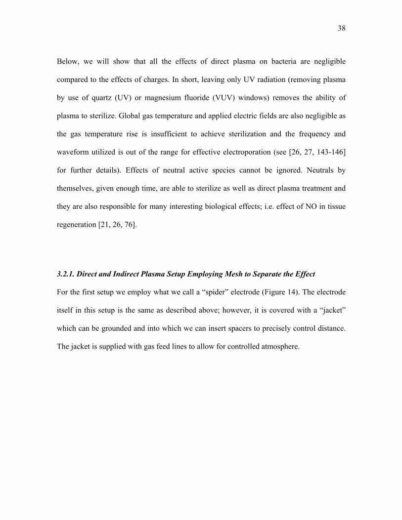
The distance between electrodes plays one of the key roles in generation of plasma and
thus for repeatable experimental results the distance needs to be precisely controlled. To
accomplish this we simply connect the round electrode to a stage that can move in Z
direction (up/down). This allows for one to repeatably measure and fix the distance
between the substrate and the electrode. Figure 9 shows a schematic of such a setup where
the electrode can be held by a “jacket” providing for the possibility of a controlled
atmosphere (use of different gases or vacuum suction); insertion or removal of a grounded
mesh which can separate plasma from the treatment target (which will be discussed in
Chapter 4); insertion of, for example MgF2 or quartz glass which will allow only
ultraviolet photons but not the rest of plasma through; and/or other additions.

28
Figure 9. Principal schematic of the FE-DBD treatment setup with removable meshes and windows. In this setup either agar with bacteria (shown), cell culture, or living tissue can be treated.
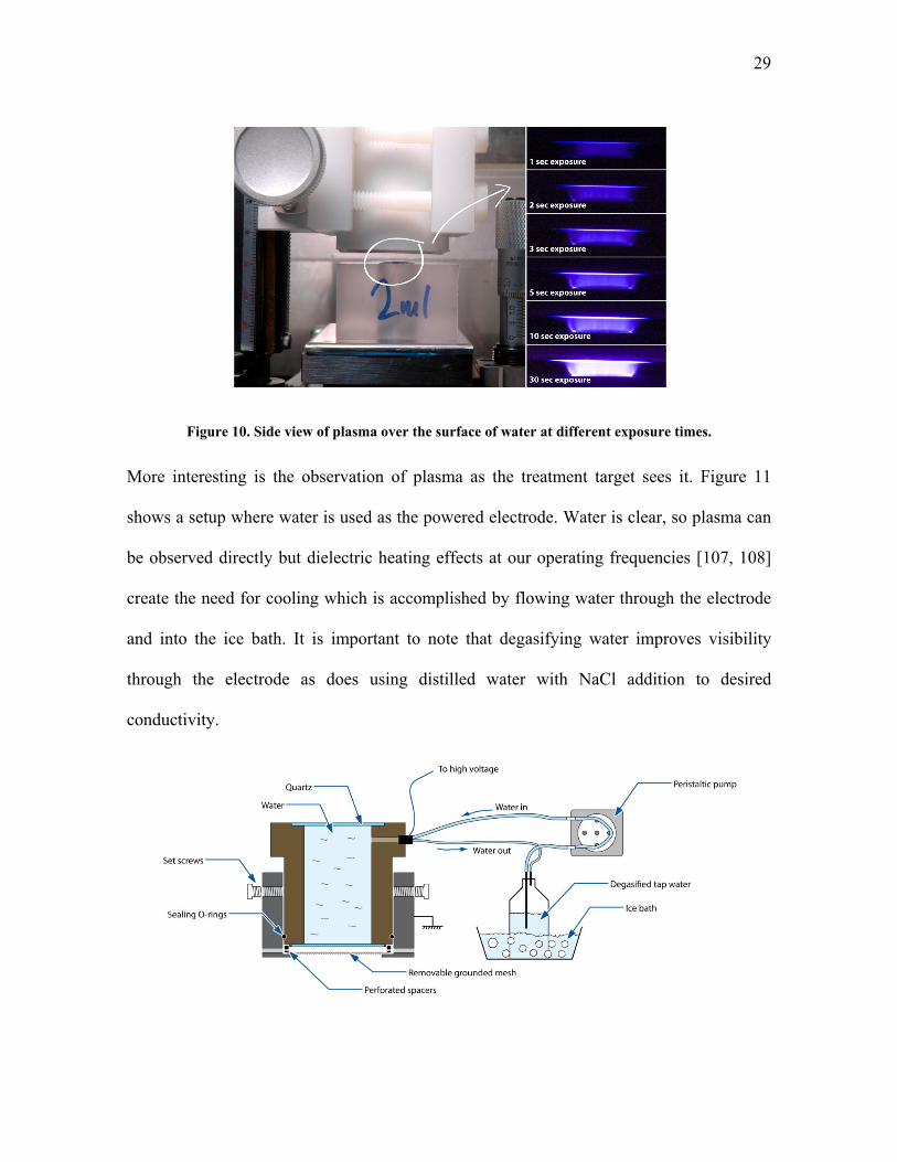
2.3. Observation of the FE-DBD Plasma
When the system is operating, plasma can be clearly seen by an observer, should they look
between the electrodes. Figure 10 shows one of such situations where photographs are
taken at different exposure times (camera shutter is left open for 1, 2, 3, 5, 10, and 30
seconds while all other parameters are kept constant). Here plasma over the water surface
is shown; tap water is used as it is conductive and it is grounded on the bottom.
29
Figure 10. Side view of plasma over the surface of water at different exposure times.
More interesting is the observation of plasma as the treatment target sees it. Figure 11
shows a setup where water is used as the powered electrode. Water is clear, so plasma can
be observed directly but dielectric heating effects at our operating frequencies [107, 108]
create the need for cooling which is accomplished by flowing water through the electrode
and into the ice bath. It is important to note that degasifying water improves visibility
through the electrode as does using distilled water with NaCl addition to desired
conductivity.

30
Figure 11. Water electrode setup schematic.
This setup allows for many different types of observations. For example, Figure 12 shows
one such observation where medical-grade dry air is flown from a gas tank at 3 slpm
through sinusoidal excitation wave discharge. Interestingly, even though plasma is
instantaneously (1/250 sec) quite non-uniform, filaments cover practically the entire area
after less than 0.2 seconds.
Figure 12. 0.004 sec (left) and 0.2 sec (right) exposures of the FE-DBD plasma in dry air (from gas tank) at 3 slpm flow rate with sinusoidal excitation wave.
Of note about Figure 12 is that we observe microfilament movement. These filaments are
approximately 0.1 mm in diameter and at these flow rates we should see them as stationary
dots. Calculating the distance the filament traveled in 1/250 sec and comparing it with
approximate flow velocity we find that they are comparable [109]. Further research is
being performed on this subject currently (see [110] for initial results and discussion).

31
CHAPTER 3. DIRECT NON-EQUILIBRIUM PLASMA APPLICATION FOR SKIN STERILIZATION; EFFECTIVENESS OF
DIRECT VERSUS INDIRECT (JET) PLASMA TREATMENT
3.1. Quantitative Direct Sterilization on Agar
Careful sample preparation is required before carrying out the plasma experiments. Since
our interest is primarily in sterilization of skin of an animal or human, bacterial samples
were collected from de-identified skin samples from human cadavers at the Hahnemann
Hospital (Philadelphia, PA). Identification of the bacterial species was performed using
standard methodology at the Hahnemann Hospital’s Clinical Microbiology Labs. Bacteria
from skin samples consisted of staphylococci, streptococci, and Candida species of yeast.
To collect these micro-organisms, six skin samples were swabbed twice each by sterile
cotton-tipped applicators pre-wetted with 10X Phosphate Buffered Saline (PBS). These
applicators were then transferred into 5 mL of 10X PBS and placed into an ultrasonic bath
for 10 minutes to lift off the bacteria from the swab. The resulting solution was transferred
onto the blood agar plate (Trypticase™ Soy Agar with 5% Sheep Blood) and incubated in
air at 37 °C for 24 hours. The resulting colonies were collected and re-inoculated onto
fresh blood agar plates and again incubated for 24 hours. These steps were repeated to
obtain large quantities of bacteria. In the end of this preparation, bacteria were collected
from the plates and diluted in 10X PBS to approximately 109 colony forming units (CFU)
per mL. Bacterial concentration was assessed by a standard dilution assay [111, 112].
Since the results of the plasma treatment are characterized below in terms of appearance of
the blood agar surface after the treatment, it is important to normalize the results by
establishing how the agar surface would look for different concentrations of colony

32
forming units (CFUs) on its surface. To do that we exposed an agar-covered Petri dish with
bacteria cultured on its surface from samples prepared as described above to the DBD
plasma for different times at fixed plasma power levels [19]. The exact plasma set-up,
surface power density, and other plasma parameters used for these normalization
experiments are the same as those used in the experiments described later that compare
direct and indirect treatment.
To quantify sterilization efficiency, 20 μL drops of 109 cfu/mL bacteria were placed on
agar surface, left to dry for 5 minutes, and finally treated by plasma. This volume was
selected as it spread to ~1 cm2 over the agar surface; thus, the area covered by the bacterial
sample drop was entirely within the area covered by the insulated plasma electrode.
Following the treatment the drop was spread over the entire agar surface and incubated in
air at 37 °C for 24 hours. Bacterial colonies (CFUs) were then counted and the results are
presented in Table 3. There is a clearly visible difference in agar appearance between
untreated, partially sterilized, and completely sterilized agar. Based on this difference, it is
reasonable to classify the appearance of the bacterial surface into 5 categories: 1) untreated
(109 cfu/mL), 2) partially disinfected (109 to 107 cfu/mL) 3) disinfected (107 to 104
cfu/mL), 4) partially sterilized (1,000 to 10 cfu/mL), and 5) completely sterilized (zero
cfu/mL). Note that the definitions of sterilization and disinfection follow those that are
accepted in the literature [19, 43, 51, 103, 113-115].
Table 3. Bacteria sterilization results (in cfu/mL)
Original Concentration
5 sec of FE-DBD
10 sec of FE-DBD
15 sec of FE-DBD
109 850 ±183 9 ±3 4 ±4

33
108 22 ±5 5 ±5 0 ±0 107 6 ±6 0 ±0 0 ±0
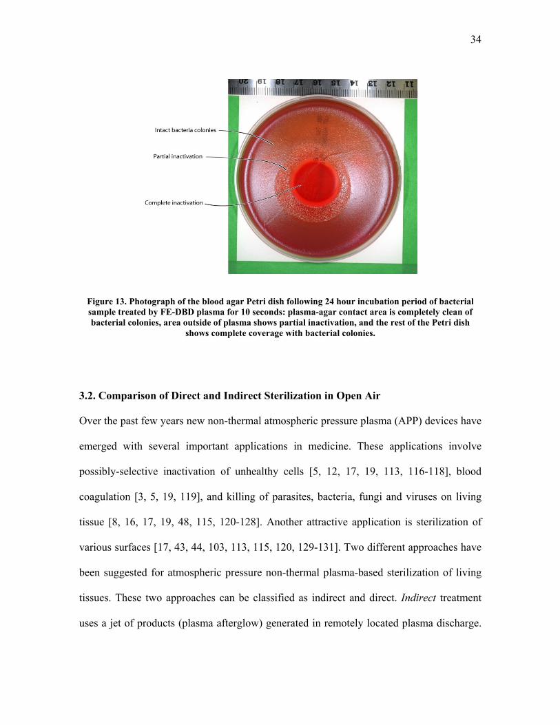
To quantify the extent of sterilization, 1 mL of 109 cfu/mL was poured over the entire agar
surface. These samples were left to dry for 3 hours and then treated by plasma. Here
plasma only covered a portion of the Petri dish. Following the 24 hour incubation period,
the extent of sterilization was clearly visible – areas where bacteria were killed looked like
uncontaminated agar while areas that received no treatment changed color and appearance
significantly as bacteria grew there. The complete sterilization area is easiest to identify –
it corresponds to the agar area that is completely clear from bacteria (for examples, see
Figure 13 or [19]). Partial sterilization is also relatively easy to define since the number of
CFUs is relatively small and can be counted. Disinfection is more difficult to assess
because of the difficulty of counting the large number of CFUs. As can be seen from
Figure 13, the complete sterilization gradually fades into untreated areas, forming a “grey-
scale” fade that gradually increases from 0 cfu/mL in the sterile zone to 109 cfu/mL in the
untreated zone much like in the quantitative experiments described in the previous
paragraph.
34
Figure 13. Photograph of the blood agar Petri dish following 24 hour incubation period of bacterial sample treated by FE-DBD plasma for 10 seconds: plasma-agar contact area is completely clean of bacterial colonies, area outside of plasma shows partial inactivation, and the rest of the Petri dish
shows complete coverage with bacterial colonies.
3.2. Comparison of Direct and Indirect Sterilization in Open Air
Over the past few years new non-thermal atmospheric pressure plasma (APP) devices have
emerged with several important applications in medicine. These applications involve
possibly-selective inactivation of unhealthy cells [5, 12, 17, 19, 113, 116-118], blood
coagulation [3, 5, 19, 119], and killing of parasites, bacteria, fungi and viruses on living
tissue [8, 16, 17, 19, 48, 115, 120-128]. Another attractive application is sterilization of
various surfaces [17, 43, 44, 103, 113, 115, 120, 129-131]. Two different approaches have
been suggested for atmospheric pressure non-thermal plasma-based sterilization of living
tissues. These two approaches can be classified as indirect and direct. Indirect treatment
uses a jet of products (plasma afterglow) generated in remotely located plasma discharge.

35
Direct treatment, by contrast, uses the tissue itself as an electrode that participates in
creating the plasma discharge, as illustrated below. Plasma in this case is contained
between the quartz surface of the powered high voltage electrode and the surface of
bacteria or tissue being treated. It is important to stress that the distinction between these
two approaches is not only related to the proximity of the plasma and the tissue, but that
direct contact with plasma brings charged energetic particles to the plasma-tissue
interface. By contrast, no charged particles are usually taken out of the plasma region by a
jet even if the plasma region is located only a fraction of a millimeter away. The question
arises: Is there a substantial difference between the two types of treatment? In other words,
is the transport of charged particles to the surface being treated as important or is the effect
of plasma due mainly to long-living active molecules and longer wavelength ultraviolet
radiation (as short wavelength “vacuum” UV is absorbed by air at atmospheric pressure
within microns) [43, 132-135].
Here we compare effectiveness of direct and indirect sterilization treatment by non-thermal
APP generated using the same discharge setup, and demonstrate that the direct treatment
can achieve sterilization much faster without any thermal effects. Specifically, we employ
the same Dielectric Barrier Discharge (DBD) to compare both types of treatment. To do
that, we carried out two types of experiments. In one set of experiments we employed a
surface covered by bacteria as a DBD electrode, placed a second smaller area DBD
electrode over it and compared the areas of sterilization with air flow parallel to the surface
and without the air flow. In another set of experiments we again employed a surface

36
covered by bacteria as one DBD electrode and compared the rate of sterilization to the case
when this surface was separated from the DBD discharge by a grounded mesh electrode.
Here we attempt to compare direct and indirect application of plasma for sterilization.
Since we are comparing two different modalities to each other, difference between them
needs to be kept to a bare minimum. The basic idea is to somehow separate the effect of
direct plasma from indirect effect of plasma afterglow. We achieve this in two setups: 1)
we separate plasma from bacteria by a grounded metal mesh; and 2) we blow pair through
plasma which is in direct contact with bacteria, thus creating a “tail” of afterglow effect.
From the previous chapters it is clear that non-thermal plasma, specifically the Floating
Electrode Dielectric Barrier Discharge, is able to achieve a medically-relevant therapeutic
effect when it is applied to living tissue. We show that FE-DBD plasma is able to sterilize
surface from bacteria while causing no visible or microscopic damage to this surface. A
question then arises: What in plasma could potentially be responsible for sterilization and
how does the effect of FE-DBD compare to application of other types of plasmas?
Different cold plasmas also show therapeutic effect, see for example Dr. Stoffels’ et al
“plasma needle” [18, 97, 98, 118, 136-138], Dr. Laroussi’s et al “plasma plume” (or
“plasma pencil”) [2, 25, 42, 44, 47, 139], or Dr. Coulombe’s et al “atmospheric pressure
glow discharge torch (APGD-t)” [12, 14, 140-142], etc.
There are two modes of application of FE-DBD to the surface being treated: 1) where the
tissue or cells are used as a second active electrode – plasma then is bound between the
dielectric surface of the powered electrode and the surface of the tissue being treated; or 2)

37
where plasma is separated from the tissue by a grounded metal mesh and gas is blown
through the discharge to carry active species outside of the plasma. We call the first
method a “direct” and the second an “indirect” application of plasma to tissue. It was
previously shown that direct application of plasma yields to roughly a two orders of
magnitude improvement in rate of bacteria inactivation as compared to indirect application,
even when the plasma is removed from tissue only a fraction of a millimeter away [27].
Effects of direct application of dielectric barrier discharges in air to bacteria can be
separated into four major categories:
1. Effects of Ultraviolet (UV) radiation. In addition to the longer wavelength UV
(180-340 nm) we also need to account for contribution of deeper UV, or Vacuum
UV1 (110-180 nm) as the plasma is in direct contact with tissue.
2. Global effects of increased gas temperature in the discharge gap and of the applied
electric field (field of the electrodes, not the self-generated field gradients at the
streamer head).
3. Effect of neutral active species generated in plasma; for example the long-living
ozone, NO, HO2, etc, or the short-living OH, atomic oxygen, electronically excited
oxygen O(1D), O2(1Δg), etc.
4. Effects of charged species: electrons and positive and negative ions.
1 VUV is absorbed in air in microns and thus cannot travel outside of the discharge zone, however in the direct plasma treatment this plasma is in direct contact with tissue and thus if the more energetic VUV photons are generated they can, in fact, reach the treatment target.
38
Below, we will show that all the effects of direct plasma on bacteria are negligible
compared to the effects of charges. In short, leaving only UV radiation (removing plasma
by use of quartz (UV) or magnesium fluoride (VUV) windows) removes the ability of
plasma to sterilize. Global gas temperature and applied electric fields are also negligible as
the gas temperature rise is insufficient to achieve sterilization and the frequency and
waveform utilized is out of the range for effective electroporation (see [26, 27, 143-146]
for further details). Effects of neutral active species cannot be ignored. Neutrals by
themselves, given enough time, are able to sterilize as well as direct plasma treatment and
they are also responsible for many interesting biological effects; i.e. effect of NO in tissue
regeneration [21, 26, 76].
3.2.1. Direct and Indirect Plasma Setup Employing Mesh to Separate the Effect
For the first setup we employ what we call a “spider” electrode (Figure 14). The electrode
itself in this setup is the same as described above; however, it is covered with a “jacket”
which can be grounded and into which we can insert spacers to precisely control distance.
The jacket is supplied with gas feed lines to allow for controlled atmosphere.
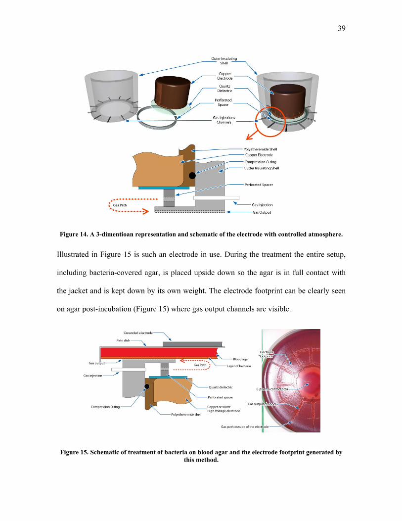
39
Figure 14. A 3-dimentioan representation and schematic of the electrode with controlled atmosphere.
Illustrated in Figure 15 is such an electrode in use. During the treatment the entire setup,
including bacteria-covered agar, is placed upside down so the agar is in full contact with
the jacket and is kept down by its own weight. The electrode footprint can be clearly seen
on agar post-incubation (Figure 15) where gas output channels are visible.
Figure 15. Schematic of treatment of bacteria on blood agar and the electrode footprint generated by this method.

40
In this setup, when plasma is turned on, we get essentially the same FE-DBD system
described above and shown schematically below in Figure 16. Let us call this setup
“direct” treatment as plasma is clearly in direct contact with bacteria. The step on the metal
jacket is 0.5 mm and the spacer is 1.5 mm tall. Thus, the distance between bacteria and
quartz is 2 mm. We can also place a grounded metal mesh between the perforated spacer
and the step on the metal jacket as is shown in Figure 17. If we then replace the 1.5 mm
spacer with a 2 mm spacer we get two setups which generate nearly identical plasmas
(with the exception of bacteria at the boundary in the first case and metal mesh in the
second, but this difference cannot be avoided in this setup and will be addresses below).
We call this an indirect treatment as plasma is separated from bacteria by the mesh. We
can now flow gas through this setup. In the case of the first setup this does not much alter
plasma, but in the case of the second one longer-living active species and radicals are
carried out of plasma while charged species (electrons and ions) are captured by the mesh.
Figure 16. Schematic of the direct/indirect treatment setup in the “direct” mode without the grounded mesh: plasma contacts bacteria directly.

41
Figure 17. Schematic of the direct/indirect treatment setup in the “indirect” mode with the grounded mesh: plasma is bound by the mesh and only the plasma afterglow can reach the surface of bacteria.
3.2.2. Direct and Indirect Plasma Setup Employing Gas Flow (Blower) to Separate the
Effect
Even though the setup presented above is able to show us clear difference between direct
and indirect application of plasma, one could argue that the plasma characteristics are
changed by introducing a metal mesh rather than moist bacteria on surface of a moist
hydrogel. For this reason and to compare the results we have introduced a second system
where only direct plasma is used but we flow air through the discharge creating the plasma
“jet” effect on the other side (Figure 18 and Figure 19). The setup is the same as above but
we have removed the jacket and added a fan to move air through plasma essentially
creating the afterglow effect on the opposite side.
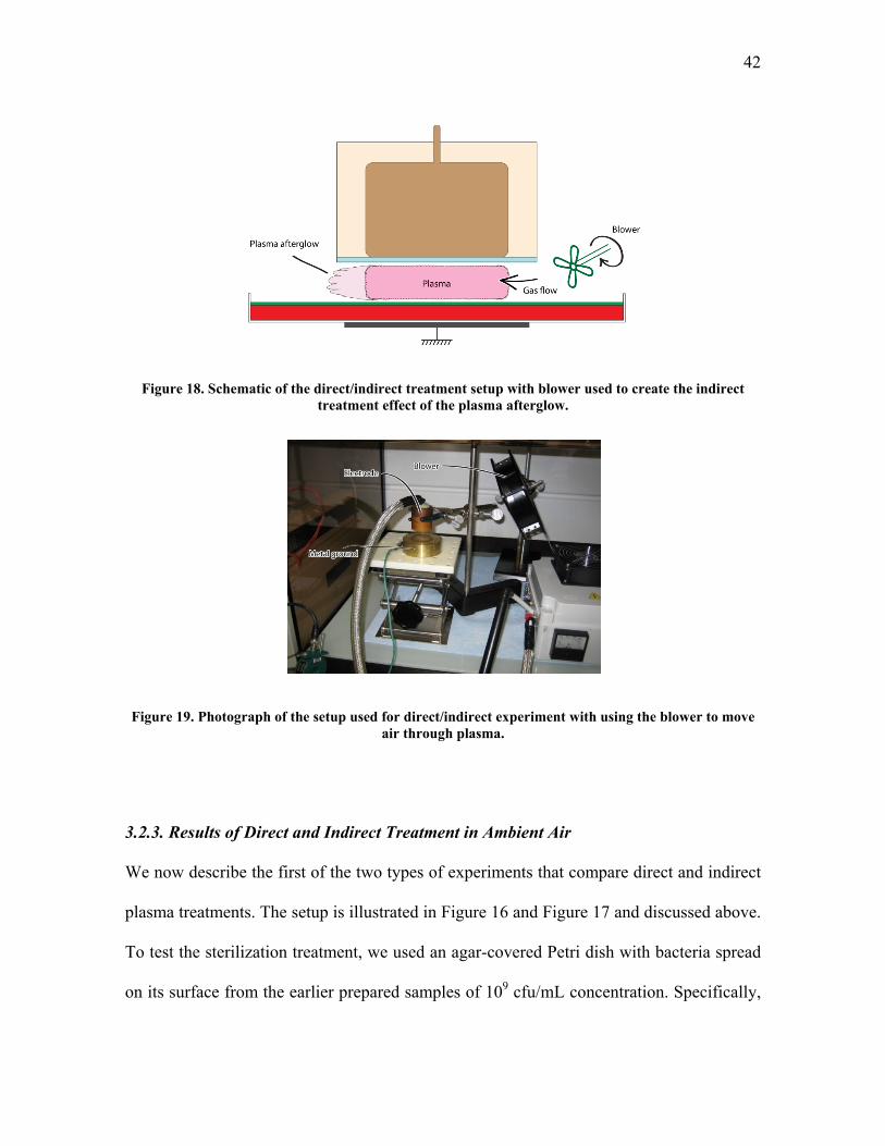
42
Figure 18. Schematic of the direct/indirect treatment setup with blower used to create the indirect treatment effect of the plasma afterglow.
Figure 19. Photograph of the setup used for direct/indirect experiment with using the blower to move air through plasma.
3.2.3. Results of Direct and Indirect Treatment in Ambient Air
We now describe the first of the two types of experiments that compare direct and indirect
plasma treatments. The setup is illustrated in Figure 16 and Figure 17 and discussed above.
To test the sterilization treatment, we used an agar-covered Petri dish with bacteria spread
on its surface from the earlier prepared samples of 109 cfu/mL concentration. Specifically,
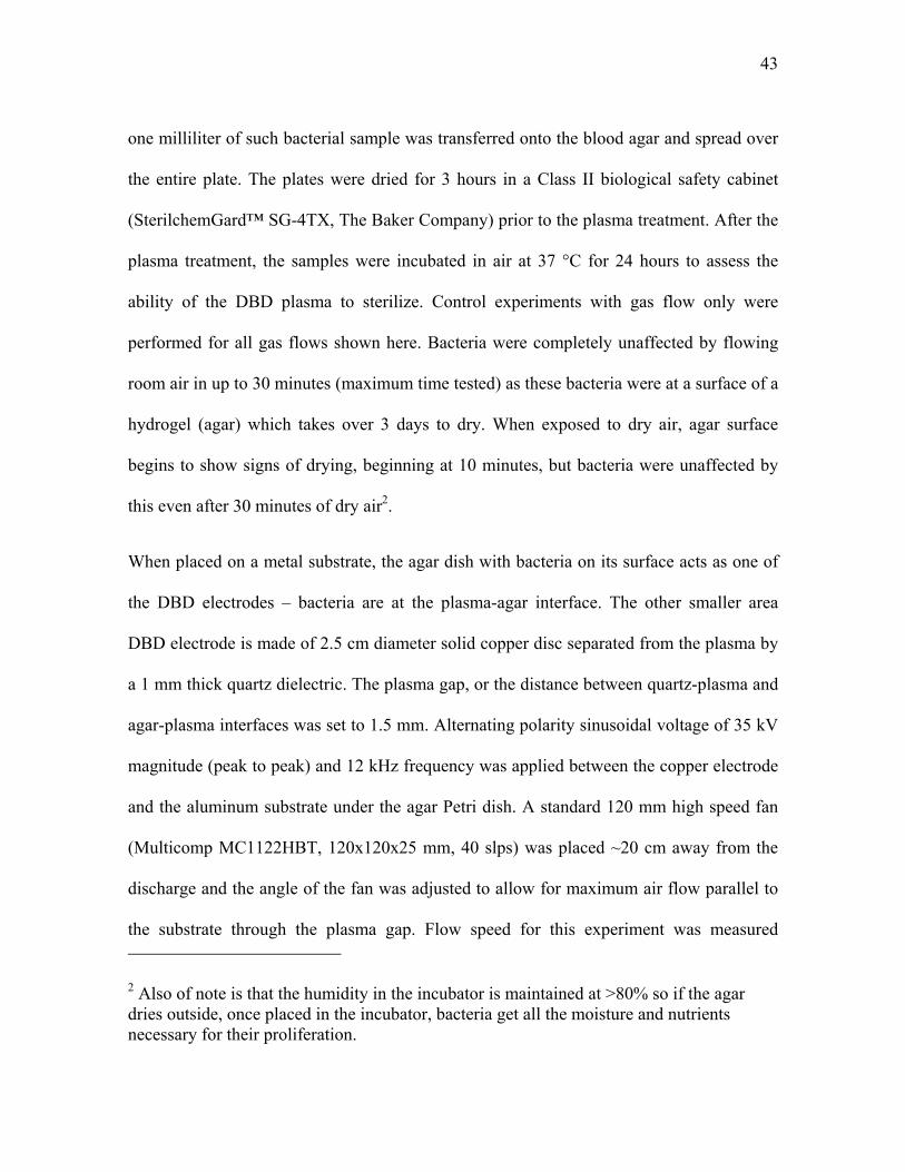
43
one milliliter of such bacterial sample was transferred onto the blood agar and spread over
the entire plate. The plates were dried for 3 hours in a Class II biological safety cabinet
(SterilchemGard™ SG-4TX, The Baker Company) prior to the plasma treatment. After the
plasma treatment, the samples were incubated in air at 37 °C for 24 hours to assess the
ability of the DBD plasma to sterilize. Control experiments with gas flow only were
performed for all gas flows shown here. Bacteria were completely unaffected by flowing
room air in up to 30 minutes (maximum time tested) as these bacteria were at a surface of a
hydrogel (agar) which takes over 3 days to dry. When exposed to dry air, agar surface
begins to show signs of drying, beginning at 10 minutes, but bacteria were unaffected by
this even after 30 minutes of dry air2.
When placed on a metal substrate, the agar dish with bacteria on its surface acts as one of
the DBD electrodes – bacteria are at the plasma-agar interface. The other smaller area
DBD electrode is made of 2.5 cm diameter solid copper disc separated from the plasma by
a 1 mm thick quartz dielectric. The plasma gap, or the distance between quartz-plasma and
agar-plasma interfaces was set to 1.5 mm. Alternating polarity sinusoidal voltage of 35 kV
magnitude (peak to peak) and 12 kHz frequency was applied between the copper electrode
and the aluminum substrate under the agar Petri dish. A standard 120 mm high speed fan
(Multicomp MC1122HBT, 120x120x25 mm, 40 slps) was placed ~20 cm away from the
discharge and the angle of the fan was adjusted to allow for maximum air flow parallel to
the substrate through the plasma gap. Flow speed for this experiment was measured
2 Also of note is that the humidity in the incubator is maintained at >80% so if the agar dries outside, once placed in the incubator, bacteria get all the moisture and nutrients necessary for their proliferation.

44
between the electrode and the substrate, directly outside of the electrode, to be 0.8 ±0.3 m/s
(EXTECH Instruments model 407123 Hot Wire Thermo-Anemometer) (see Figure 18 and
Figure 19).
The power surface density delivered into the plasma discharge was measured by two
methods. One was the more traditional electrical measurement method involving voltage
across the discharge and current into it. This measurement was performed using a high
speed high voltage probe (PVM-4 1000:1, North Star High Voltage, Marana, AZ) and high
speed current probe (1 V/Amp +1/-0% sensitivity, 10 ns usable rise time, 35 MHz
bandwidth, Model 4100 Current Monitor, Pearson Electronics, Palo Alto, CA). Signals
from the probes were measured and integrated using a high speed oscilloscope (500 MHz
bandwidth, 5x10⁹ samples/s, TDS5052B, Tektronix, Inc, Richardson, TX). These electrical
measurements were confirmed using custom-built calorimetric measurement set-up. Both
electrical and calorimetric measurements indicated the power of 0.8 ±0.2 W/cm2.
When there is no air flow parallel to the surface, the area directly under the second smaller
electrode is exposed simultaneously to charged particles, UV, and the plasma afterglow
containing longer living active plasma components such as ozone (O3), nitric oxide (NO),
hydroxyl radicals (OH), and other excited molecular and atomic species. In the presence of
the airflow, the area under the second smaller electrode experiences practically the same
conditions as without the flow. However, in the presence of flow the plasma afterglow will
also impinge on the areas of the substrate that are not directly under the second smaller
electrode as it is illustrated in Figure 18.
45
It should be stressed that, even in the absence of any flow, the sterilization region is not
confined to the diameter of the copper electrode. With increasing treatment time, this
region extends several millimeters outside the electrode [20, 27]. There are two reasons for
this: first, due to the existence of surface discharge near the base of DBD filaments, the
“footprint” of a micro-channel is substantially larger than its diameter [19, 147]. Second,
since the field lines originating near the edge of the insulated electrode tend to spread out
slightly, the discharge filaments also spread out beyond the area of the top electrode. The
flow, however, is not expected to change the shape of the plasma discharge region because
it is not capable of moving the filaments further than a fraction of a millimeter, as was
observed with high speed photography (not shown) as well as theoretically [147, 148].
However, such effects are expected to be confined to within millimeters from the edge of
the copper electrode, while the longer living active species and radicals can spread much
further with gas flow [43, 97, 103, 147-149].
The results comparing the sterilization with and without flow are illustrated in Figure 20
and zoomed in version in Figure 21. As can be seen from these figures, complete
sterilization by direct plasma treatment under the insulated electrode is achieved in 15
seconds. If air is passed parallel to the substrate through the plasma region, the disinfection
area shifts by several millimeters, but a “tail” of disinfection appears. Even though
complete sterilization is not observed in this “tail”, different degrees of disinfection are
evident. Locations closer to the plasma region have greater degree of disinfection. This
suggests that plasma “afterglow”, or the gas carried through and outside of plasma, does
contain active species and radicals that have bactericidal effects, although direct plasma is

46
substantially more potent as a sterilizing agent. Complete sterilization, however, did not
extend to the region reachable by the plasma afterglow in as much as 5 minutes of
treatment. This clearly demonstrates that longer living active species generated in plasma
are much less effective than direct plasma where charged particles participate in the
process.
Figure 20. Using a blower to shift sterilization region does not affect plasma and shows little effect of the afterglow: 15 seconds of treatment with (a) blower off and (b) blower on (air flows up). Note:
arrow is painted on the back of the dish and shows through on the photograph.
Figure 21. Zoomed in photograph of the bacterial growth results following plasma treatment and incubation (photograph is converted to black and white for increased contrast). Note: arrow is painted
on the back of the dish and shows through on the photograph.
47
In the first type of experiments described above, effects of plasma “afterglow” were
separated from the effects of charged particles and from the UV radiation. In the second
type of experiments described below, plasma afterglow together with UV is compared
against the direct plasma, involving also charged particles. The direct treatment is obtained
similarly to the first type of experiments described above. However, instead of creating
airflow parallel to the substrate, provisions were made to allow introduction of air at
different flow rates into the discharge gap (see Figure 16 and Figure 17). To obtain indirect
treatment including UV effects, agar surface covered by bacteria was again employed as
one DBD electrode; however, this surface was separated from the DBD discharge by a
mesh electrode, as illustrated in Figure 17. With a grounded mesh in place, bacteria are no
longer at the plasma interface, as plasma is bound between the grounded mesh and the
quartz-covered electrode. The mesh (22.04 wires per cm, 0.1016 mm wire diameter, 0.351
mm opening, 60% open area, weaved mesh) is placed 1 mm above the surface of the agar,
which permits only the passage of ultraviolet radiation and longer wavelength photons (not
vacuum UV), gas, radicals and other longer living particles created in the plasma gap
between the mesh and the quartz-insulated electrode above it. The second electrode used
with the mesh was the same electrode that was employed in the direct treatment setup
illustrated Figure 16. The gap between the mesh and the second electrode is set at 1.5 mm,
just as in the plasma gap of the direct treatment setup. The setup used to introduce air into
the discharge gap at 3 different flow rates (1, 5, and 10 slpm, corresponding to flow speeds
of 0.078, 0.393, and 0.853 m/s through the mesh) is illustrated in Figure 17. The air was
introduced into the discharge gap to enhance extraction of the plasma afterglow through

48
the mesh. In both direct (without the mesh) and indirect (with the mesh) situations the
same air flow rates were employed and the discharge was calibrated to the same plasma
power for both cases.
To ensure that both setups, with and without the mesh, produce the same UV radiation, we
correct for the UV transparency of the mesh using separate measurements. Regular paper is
placed over the light source in these measurements to diffuse the light and a spectrum is
measured using TriVista Spectrometer System with Princeton Instruments PIMAX
intensified CCD camera with only paper, and with paper and mesh. It turns out that the
mesh cuts off roughly ~40% of visible light and ~20-40% of UV light depending on the
wavelength of UV (Figure 22 – graph in visible light range and Figure 23 – measurements
in ultraviolet range).
Figure 22. Results of measurement of light intensity in the visible spectrum for no mesh, fine mesh, and coarse mesh.

49
Figure 23. Results of measurement of light intensity in the ultraviolet spectrum measured at three peaks (239.5 nm, 263.54 nm, and 284.03 nm) without mesh (taken as 100%) and with mesh.
The results comparing direct (without the mesh) and indirect (with the mesh) sterilization
are illustrated in Figure 24. It is clearly visible that plasma that comes in direct contact
with bacteria is able to sterilize significantly faster than afterglow or jet. Only 5 seconds of
direct plasma treatment results in the appearance of inactication region (spot near the
center). Complete sterilization occurs within 15 seconds when direct treatment is employed
and only partial disinfection can be achieved within the same time frame with indirect
treatment. Over 5 minutes of indirect treatment is required to achieve sterilization results
similar to direct treatment obtained within 15 seconds. Therefore, even with substantial
UV radiation, indirect plasma treatment is significantly weaker than direct plasma which
includes bactericidal effects due to charged particles.

50
Figure 24. Direct application of plasma yields to better sterilization efficiency than treatment by plasma afterglow: (a) 5 seconds and (b) 15 seconds of direct plasma compared with (c) 30 seconds and
(d) 2 minutes of plasma jet.
3.3. Effects of UV Radiation, Applied Electric Field, Thermal Energy, and Other
Indirect Plasma Effects
Several possibilities exist that might explain why bacteria inactivation, disruption of
membrane’s normal functions, or disruption of normal metabolism functions occurs only
in the presence of the DBD discharge. One possibility is that UV radiation (probably in the
UV-C band) works in synergy with chemically active species produced by direct plasma in
the liquid surrounding the organisms to break the integrity of cellular membranes (Figure
25 – emission spectra from plasma in UV range). Photon energy of the UV-C radiation
(about 4-6 eV) is sufficient to break some chemical bonds in bio-molecules [150]. More
energetic VUV-photons, however, are unable to penetrate deep through the layer of liquid
and through bacterial membrane [151-153]. The UV-C radiation can be effectively
delivered to the membrane, but its energy can be sufficient also for structural
reorganization of the bio-molecules (including fatal but slow DNA changes), and
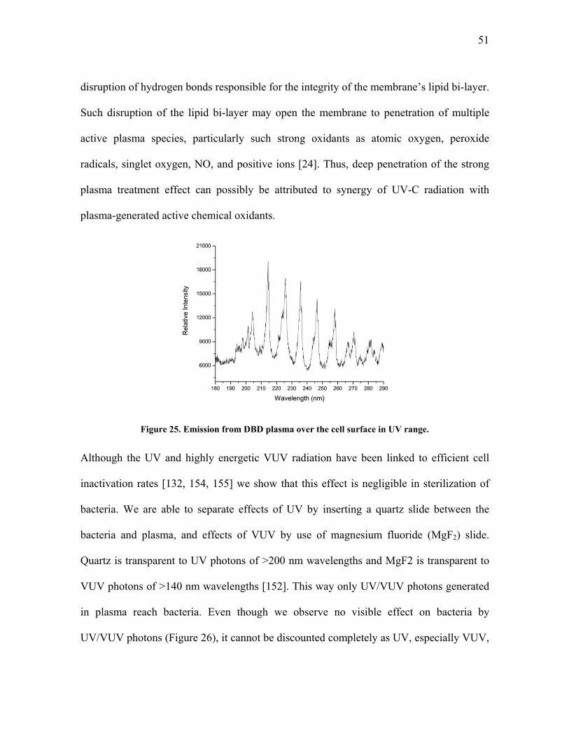
51
disruption of hydrogen bonds responsible for the integrity of the membrane’s lipid bi-layer.
Such disruption of the lipid bi-layer may open the membrane to penetration of multiple
active plasma species, particularly such strong oxidants as atomic oxygen, peroxide
radicals, singlet oxygen, NO, and positive ions [24]. Thus, deep penetration of the strong
plasma treatment effect can possibly be attributed to synergy of UV-C radiation with
plasma-generated active chemical oxidants.
Figure 25. Emission from DBD plasma over the cell surface in UV range.
Although the UV and highly energetic VUV radiation have been linked to efficient cell
inactivation rates [132, 154, 155] we show that this effect is negligible in sterilization of
bacteria. We are able to separate effects of UV by inserting a quartz slide between the
bacteria and plasma, and effects of VUV by use of magnesium fluoride (MgF2) slide.
Quartz is transparent to UV photons of >200 nm wavelengths and MgF2 is transparent to
VUV photons of >140 nm wavelengths [152]. This way only UV/VUV photons generated
in plasma reach bacteria. Even though we observe no visible effect on bacteria by
UV/VUV photons (Figure 26), it cannot be discounted completely as UV, especially VUV,
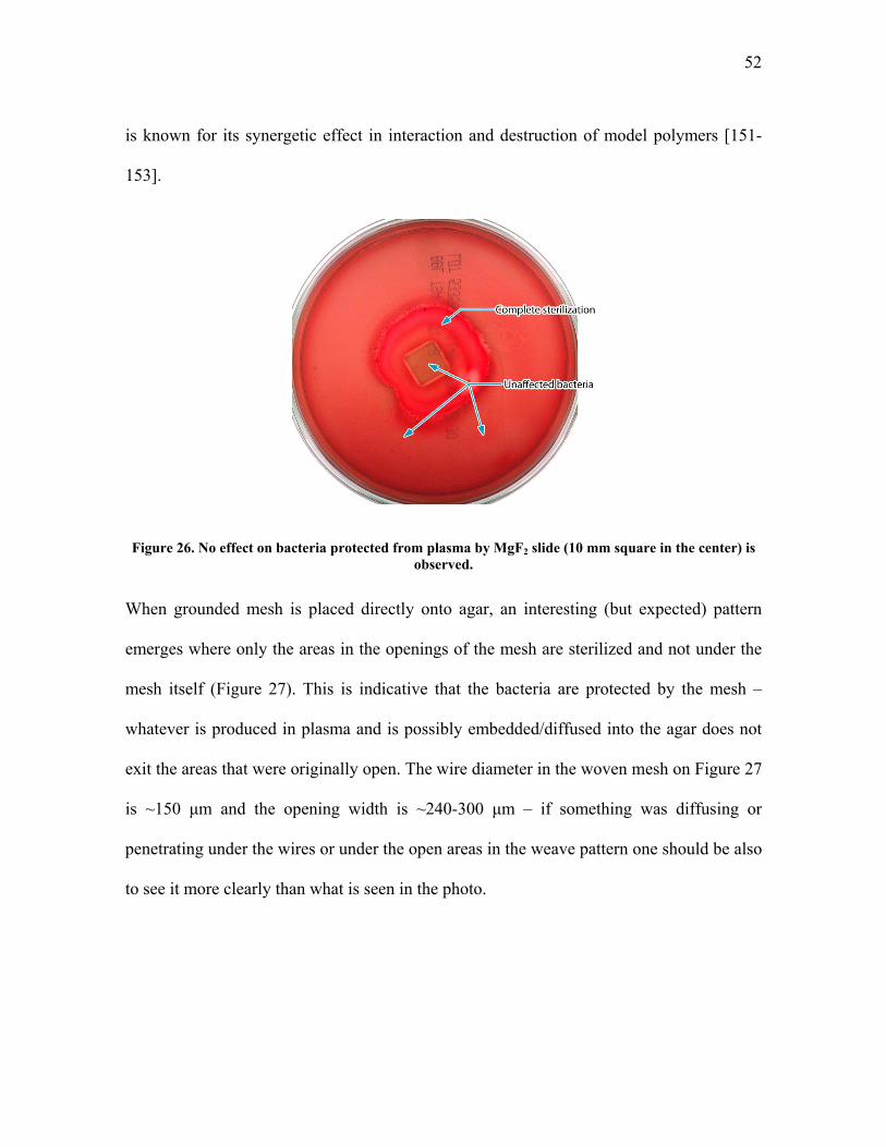
52
is known for its synergetic effect in interaction and destruction of model polymers [151-
153].
Figure 26. No effect on bacteria protected from plasma by MgF2 slide (10 mm square in the center) is observed.
When grounded mesh is placed directly onto agar, an interesting (but expected) pattern
emerges where only the areas in the openings of the mesh are sterilized and not under the
mesh itself (Figure 27). This is indicative that the bacteria are protected by the mesh –
whatever is produced in plasma and is possibly embedded/diffused into the agar does not
exit the areas that were originally open. The wire diameter in the woven mesh on Figure 27
is ~150 μm and the opening width is ~240-300 μm – if something was diffusing or
penetrating under the wires or under the open areas in the weave pattern one should be also
to see it more clearly than what is seen in the photo.

53
Figure 27. Grounded mesh placed directly on bacteria (no space) generates interesting pattern: only mesh openings are sterilized (magnified area is color-corrected for clarity).
High electric fields, especially pulsed electric fields are known to inactivate bacteria
in solution 64, 156‐158 . The field strength required for this, however, is on the
order of a megavolt per centimeter – significantly higher than the applied electric
field we are employing which is on the order of 10 to 30 kV. Experimentally, if we
apply electric field at the strength just below the breakdown potential we observe
absolutely no effect on bacteria as the agar looks complete unaffected by this
following 24 hour incubation. We cannot, however, completely discount the effect of
the electric field. In the head of a developing streamer, the electric field are much
higher and can be estimated to be:
· 3.
2.6 · 10 V/cm
where is the field at the head of a needle‐streamer of length 0.2 cm and radius
0.1 cm at the applied field of 35 kV. Field needed to destroy a chemical bond is

54
on the order of 3V/3Å 108 V/cm; to break a Hydrogen bond 107 V/cm; and to
break Van der Waals bond 106 V/cm. It is also known that ~1 Volt applied across a
cell membrane ~ 3 nm thick is able to depolarize and break it 156, 159‐161 . Field
needed for this is 1V/3nm 3 106 V/cm. Thus, electric field at the head of streamer as
it reaches the bacteria surface is sufficient to open the membrane and thus potentially
lead to leakage of cellular contents out and various substances detrimental to the
organism into the cell.
3.4. Direct and Indirect Plasma Treatment in Various Gases
Additional experiments were performed to analyze behavior of plasma and its
sterilization ability in different gases. Five areas were observed following the
treatment: (1) right under the electrode, (2) outside of the electrode but inside of the
treatment area bound by legs, (3) inside of the gas channel, (4) immediately outside of the
gas channel, and (5) outer parts of the dish not in the direct gas path (Figure 28). Effect of
treatment was observed following the 24-hour incubation and rated from 0 (no visible
effect) to 5 (complete sterilization). For example, Petri dish in Figure 28 would be rated as
1-2 (visible disinfection in area right under the electrode), 2-1, 3-1, 4-1, and 5-0. Detailed
results for various gases are presented in Table 4. Dry gas was obtained from the cylinder
or bubbled through sterile deionized water to increase humidity. Humidity was measured
to 80% when air was used (both for 1, 3, and 10 slpm flow rates) and not measured for
other gases. Basic conclusion of this study is that oxygen is required for fast and effective

55
inactivation of bacteria and inactivation rate depends little on the exact gas composition,
purity (determined by gas flow rate and, of course, the grade used), or humidity.
Figure 28. Identification of different areas under the FE-DBD electrode following the plasma treatment and 24-hour incubation: (1) under the electrode, (2) outside of the electrode but inside of the treatment area bound by legs, (3) inside of the gas channel, (4) immediately outside of the gas channel,
and (5) outer parts of the dish not in the direct gas path.
Table 4. Results of treatment of bacteria by FE-DBD plasma in different gases. Areas of treatment are identified in Figure 28. Note: all experiments are repeated in triplicate and the results presented here
are averaged.
Dry Gas Time Flow Area
or Wet (sec) (slpm) 1 2 3 4 5
Dry air 5 1 1 1 0 0 0
Dry air 10 1 2 1 1 0 0
Dry air 30 1 5 1 2 1 0
Dry Ar 5 1 0 0 0 0 0
Dry Ar 10 1 1 0 0 0 0
Dry Ar 30 1 1 0 0 0 0
Dry He 5 1 0 0 0 0 0
Dry He 10 1 1 0 0 0 0
Dry Gas Time Flow Area
or Wet (sec) (slpm) 1 2 3 4 5
Dry N2 5 10 1 0 0 0 0
Dry N2 10 10 1 0 0 0 0
Dry N2 30 10 1 0 0 0 0
Dry N2‐NO 5 10 1 0 0 0 0
Dry N2‐NO 10 10 1 0 0 0 0
Dry N2‐NO 30 10 2 1 0 0 0
Dry O2 5 10 2 1 2 2 0
Dry O2 10 10 2 1 2 2 1
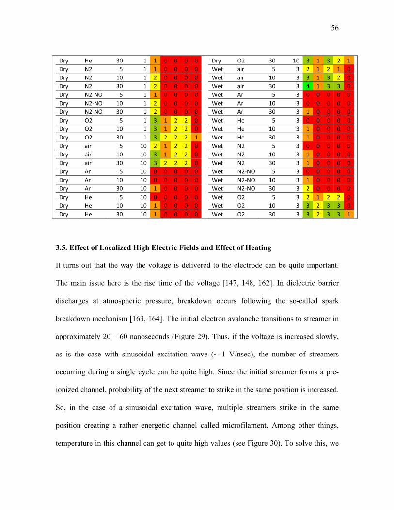
56
Dry He 30 1 1 0 0 0 0
Dry N2 5 1 1 0 0 0 0
Dry N2 10 1 2 0 0 0 0
Dry N2 30 1 2 0 0 0 0
Dry N2‐NO 5 1 1 0 0 0 0
Dry N2‐NO 10 1 2 0 0 0 0
Dry N2‐NO 30 1 2 0 0 0 0
Dry O2 5 1 3 1 2 2 0
Dry O2 10 1 3 1 2 2 0
Dry O2 30 1 3 2 2 2 1
Dry air 5 10 2 1 2 2 0
Dry air 10 10 3 1 2 2 0
Dry air 30 10 3 2 2 2 0
Dry Ar 5 10 0 0 0 0 0
Dry Ar 10 10 0 0 0 0 0
Dry Ar 30 10 1 0 0 0 0
Dry He 5 10 0 0 0 0 0
Dry He 10 10 1 0 0 0 0
Dry He 30 10 1 0 0 0 0
Dry O2 30 10 3 1 3 2 1
Wet air 5 3 2 1 2 1 0
Wet air 10 3 3 1 3 2 0
Wet air 30 3 4 1 3 3 0
Wet Ar 5 3 0 0 0 0 0
Wet Ar 10 3 0 0 0 0 0
Wet Ar 30 3 1 0 0 0 0
Wet He 5 3 0 0 0 0 0
Wet He 10 3 1 0 0 0 0
Wet He 30 3 1 0 0 0 0
Wet N2 5 3 0 0 0 0 0
Wet N2 10 3 1 0 0 0 0
Wet N2 30 3 1 0 0 0 0
Wet N2‐NO 5 3 0 0 0 0 0
Wet N2‐NO 10 3 1 0 0 0 0
Wet N2‐NO 30 3 2 0 0 0 0
Wet O2 5 3 2 1 2 2 0
Wet O2 10 3 3 2 3 3 0
Wet O2 30 3 3 2 3 3 1
3.5. Effect of Localized High Electric Fields and Effect of Heating
It turns out that the way the voltage is delivered to the electrode can be quite important.
The main issue here is the rise time of the voltage [147, 148, 162]. In dielectric barrier
discharges at atmospheric pressure, breakdown occurs following the so-called spark
breakdown mechanism [163, 164]. The initial electron avalanche transitions to streamer in
approximately 20 – 60 nanoseconds (Figure 29). Thus, if the voltage is increased slowly,
as is the case with sinusoidal excitation wave (~ 1 V/nsec), the number of streamers
occurring during a single cycle can be quite high. Since the initial streamer forms a pre-
ionized channel, probability of the next streamer to strike in the same position is increased.
So, in the case of a sinusoidal excitation wave, multiple streamers strike in the same
position creating a rather energetic channel called microfilament. Among other things,
temperature in this channel can get to quite high values (see Figure 30). To solve this, we

57
have employed pulses rather than sinusoidal wave allowing for voltage rise time of ~ 5
V/nsec and pulse duration of a few microseconds [143, 165]. Time between pulses is
sufficient for the gas to return to the initial conditions so that during the next pulse
streamers again strike randomly [147, 148, 162]. Of course, decreasing the pulse duration
even further would lead to even better conditions for surface treatment; we will discuss this
later in this section.
Figure 29. Avalanche transition to streamer [162].
These power supply systems operate on the basis of voltage amplification: a low voltage
pulse or a sinusoidal wave is generated, then the current is amplified, and is finally passed
through a transformer with high turns ratio. High voltage signal is then taken from the
transformer’s secondary coil and collected to the load [19]. For power analysis of these
systems (plasma in continuous sinusoidal wave or pulsed mode) we measure current
passing through plasma and the voltage drop in the gap. For current analysis we utilized a
magnetic core current probe (1 Volt/Ampere +1/-0% Sensitivity, 10 nanoseconds usable
rise time, 35 MHz bandwidth, Model 4100 Pearson Current Monitor, Pearson Electronics,
Palo Alto, CA). Voltage was measured using a wide bandwidth voltage probe (PVM-4
1000:1, North Start High Voltage, Marana, AZ). Signals were acquired and recorded by a

58
Digital Phosphor Oscilloscope (500 MHz bandwidth, 5·109 samples/s, TDS5052B,
Tektronix, Inc, Richardson, TX). Acquired data was then integrated in MATLAB. Due to
the limitations of the probes, this system cannot be used to analyze the power deposited
into nanosecond pulsed plasma.
In general, DBD plasmas are deemed “non-thermal” as the temperature of ions is
significantly lower than that of electrons. However, especially in more filamentary
regimes, temperature in the filament can grow above room temperature and potentially
damage the surface being treated, particularly in the case of sensitive surfaces like in
polymer surface treatment or in biological applications [24, 162]. For this reason we have
employed emission spectroscopy to measure the vibrational and rotational temperatures in
plasma. The temperature measurements were made utilizing the 375.4 nm and 380.4 nm
vibrational lines and the rotational structure in those regions of the second positive system
of nitrogen. An experimentally obtained spectrum was compared to the simulated spectrum
to obtain vibrational and rotational temperatures (this procedure has been described in
detail previously [149, 166, 167]). A fiber‐optic bundle (Princeton Instruments‐Acton,
10 fibers – 200 μm core) was utilized to acquire the emission from the discharge and
to transmit it to a spectrometer (Acton Research SpectraPro 500i with Roper
Scientific model 7430 CCD camera) and spectra were digitally acquired with
approximately 0.6 nm resolution. Temperature of the camera was set to ‐25°C.
Typical acquisition time for the spectra was 10 s. Background images (with the
discharge turned off) were subtracted and a low pressure mercury lamp was used to
determine the slit function of the spectrometer. Entrance slit width was set to 85 μm

59
when acquiring emission from the discharge and/or the mercury lamp. The room
temperature was 22°C throughout the spectroscopic measurements.
As seen in Figure 30, the temperatures within the filaments of “continuous” and “pulsed”
FE-DBD were found to be about 500 K and 300 K respectively by model fit to 2nd positive
Nitrogen system. This method measures temperature based on radiation from the
discharge. Since radiation is highest from the microfilament area we assume that the
measured temperatures come from that region while gas temperature outside of the
microfilament remains at room temperature.
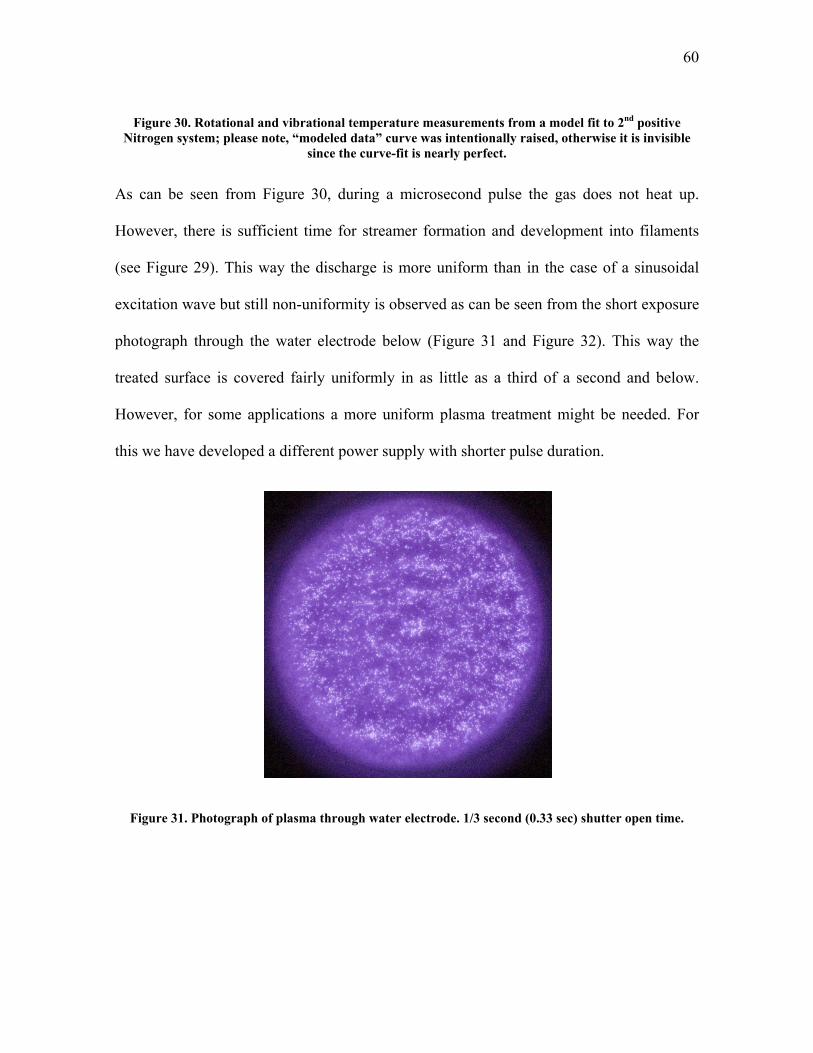
60
Figure 30. Rotational and vibrational temperature measurements from a model fit to 2nd positive Nitrogen system; please note, “modeled data” curve was intentionally raised, otherwise it is invisible
since the curve-fit is nearly perfect.
As can be seen from Figure 30, during a microsecond pulse the gas does not heat up.
However, there is sufficient time for streamer formation and development into filaments
(see Figure 29). This way the discharge is more uniform than in the case of a sinusoidal
excitation wave but still non-uniformity is observed as can be seen from the short exposure
photograph through the water electrode below (Figure 31 and Figure 32). This way the
treated surface is covered fairly uniformly in as little as a third of a second and below.
However, for some applications a more uniform plasma treatment might be needed. For
this we have developed a different power supply with shorter pulse duration.
Figure 31. Photograph of plasma through water electrode. 1/3 second (0.33 sec) shutter open time.

61
Figure 32. Photograph of plasma through water electrode. 1/320 second (0.0031 sec) shutter open time.
We have designed a system for the generation of high voltage, pulsed, periodic dielectric
barrier or corona discharges capable of being used in the presence of conductive liquid
droplets and over contaminated surfaces. This system can be used, for example, in different
devices for generation of uniform dielectric barrier discharge plasma for treatment and
sterilization of various uneven and contaminated surfaces. One of the main difficulties in
the development of high voltage short pulsed power supplies is the matching of energy of
the pulse generated by the power supply with the energy dissipated in the load. The other
important problem is switching off of the high voltage switcher after the pulse subsides.
Our so-called nanosecond-pulsed system solves both of these problems and gives us
possibility to produce high efficiency generator of extremely short pulses with using
reliable and simple pulse switcher like an uncontrolled spark gap.

62
The system is based on controllable fast charging of a capacitor and then discharging of
this capacitor through a series of two spark gaps. This system was discussed in detail
previously (see [165]) but the basic principle of operation is as follows. There are two
spark gaps and the load connected in parallel with the second spark gap. When the first
spark gap discharges, the voltage is applied then simultaneously to the second spark gap
and the load. Thus, the voltage applied to the load is defined by the primary spark gap and
the duration of the pulse is defined by the second spark gap. Additionally, time between
these pulses is defined by the rate of charging of the capacitor. The result of the method is
the formation of high voltage pulses with an extremely short rise time, for example, up to
5-20 nanoseconds, and with high pulse repetition frequency, for example, up to 2,000 Hz.
The high voltage pulses facilitate maximum efficiency plasma chemical oxidation of
detrimental impurities, and increase the range of stable discharge operation in the presence
of droplets of water or other conductive liquids in the discharge zone. Details of
construction and operation of such a device have already been discussed earlier (see [168]).

63
Figure 33. Oscillogram of the nanosecond pulse voltage and current. Voltage rises to ~ 30 kV in ~ 10 ns, or 3,000 V/ns.
Figure 35 shows a result of application of ultra-short high voltage pulses to the FE-DBD
setup in Figure 34. This setup allows to quickly move photographic film through plasma
discharge. When the discharge is in pulsed mode and the time between pulses is kept
sufficiently long (a few hundred Hz) we are able to get an image of a single pulse of
plasma on the film plane. The result is a Lichtenberg figure of a completely uniform
plasma field. Thus, this setup is able to generate a completely uniform and filament-free
plasma at atmospheric pressure and temperature in open air, which can potentially be
important for many applications where plasma discharge uniformity is of concern, for
example in sterilization of living human tissue or in other applications (see, for example,
[19, 26]).
Figure 34. Diagram of a setup to capture a single pulse of Dielectric Barrier Discharge plasma on photographic film.

64
Figure 35. Image produced on black and white photographic film (100 ISO sensitivity negative film) by a single nanosecond pulse of DBD plasma.
For comparison with the uniform plasma pulse produced by the nanosecond excitation
(Figure 35) we are able to run the same experiment using the microsecond excitation
pulses. The resulting Lichtenberg figure is shown in Figure 36. The microfilament pattern
produced on film is identical to that predicted theoretically and observed experimentally in
the past, and thus we can assume that we are in fact observing non-uniform plasma [147,
148, 162]. Continuous excitation wave plasma looks similar on the film however since the
plasma is on for a significant portion of the time the image on film results in something
that is difficult to decipher unless the film movement speed is beyond that of the
capabilities of our experimental setup.

65
Figure 36. Image produced on black and white photographic film (100 ISO sensitivity negative film) by a single microsecond pulse of DBD plasma.
3.6. Summary of Direct with Indirect comparison of FE-DBD Plasma Application to
Tissue
By this point we have discussed the need for a non-thermal plasma treatment in Chapter 1
and introduced such a system in Chapter 2. Various modifications of dielectric barrier
discharges have already been used by other research groups in the past for surface
modification without excessive damage to this surface (see [59, 61, 119, 124, 169-177] for
examples). Our task, though, requires direct contact of plasma not with some polymer
surface but with a living object. We showed that plasma can safely be put in contact with
living tissue where charges are brought to the surface of the organism. This direct
treatment was shown to achieve desired effect of sterilization orders of magnitude faster
than in the case on indirect treatment by the plasma affluent. Here we understood by what
means plasma is able to achieve this desired effect and showed that charged species

66
(electrons and positive and negative ions) are responsible for the effect. Neutral and
excited species also must play an important role in inactivation of bacteria but the presence
of charges is essential in achieving the desired effect, at least when the bacteria are treated
in room conditions on skin or skin-like surfaces. In the following chapter we will discuss
application of the FE-DBD plasma system in non-damaging skin sterilization of human
cadavers, and live mice and pigs.

67
CHAPTER 4. DIRECT NON-DAMAGING TREATMENT BY NON-EQUILIBRIUM PLASMA OF LIVING TISSUE: TOXICITY TRIALS
A topical tissue treatment which induces damage would have a questionable medical use.
Our goal in this chapter is to discuss the extent of damage, if any, FE-DBD plasma causes
to tissue that it comes in contact with. Some medical treatments, i.e. sterilization of intact
skin before surgery or needle insertion, would require no damage to skin, while other
treatments, i.e. tattoo removal or removal of necrotic tissue from ulcer surface, would
require some degree of precisely controlled damage. We also envision sterilization of open
wounds and ulcerating wounds as one of the possible uses of FE-DBD plasma and thus
extent of toxicity of the treatment under such conditions needs to be evaluated.
To evaluate the extent of damage FE-DBD plasma treatment causes to tissue, we employ a
method known as the “differential skin toxicity trial” [178-182]. In this method, we locate
the dose at which damage can be clearly observed both visually and microscopically and
then reduce the dose. Once the maximum dose at which no damage is observed is located,
more treatments are made around that dose and statistical information is collected. Dose is
determined by the combination of plasma power and treatment time; i.e. high power short
treatment or low power long treatment. For example, if at 1 Watt/cm2 of plasma surface
power density we observe no damage starting from 60 seconds of treatment then we repeat
treatments on 3 samples each at 55, 60, and 65 seconds. If no damage is observed at 55 and
60 seconds while some minor damage is visible at 65 seconds, then 60 second treatment at
1 Watt/cm2 is deemed the maximum acceptable dose (here dose is 60 sec x 1 Watt/cm2 =
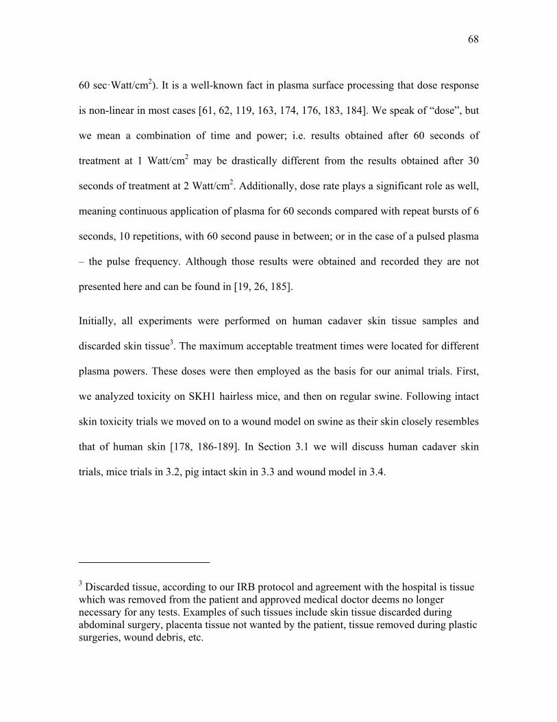
68
60 sec·Watt/cm2). It is a well-known fact in plasma surface processing that dose response
is non-linear in most cases [61, 62, 119, 163, 174, 176, 183, 184]. We speak of “dose”, but
we mean a combination of time and power; i.e. results obtained after 60 seconds of
treatment at 1 Watt/cm2 may be drastically different from the results obtained after 30
seconds of treatment at 2 Watt/cm2. Additionally, dose rate plays a significant role as well,
meaning continuous application of plasma for 60 seconds compared with repeat bursts of 6
seconds, 10 repetitions, with 60 second pause in between; or in the case of a pulsed plasma
– the pulse frequency. Although those results were obtained and recorded they are not
presented here and can be found in [19, 26, 185].
Initially, all experiments were performed on human cadaver skin tissue samples and
discarded skin tissue3. The maximum acceptable treatment times were located for different
plasma powers. These doses were then employed as the basis for our animal trials. First,
we analyzed toxicity on SKH1 hairless mice, and then on regular swine. Following intact
skin toxicity trials we moved on to a wound model on swine as their skin closely resembles
that of human skin [178, 186-189]. In Section 3.1 we will discuss human cadaver skin
trials, mice trials in 3.2, pig intact skin in 3.3 and wound model in 3.4.
3 Discarded tissue, according to our IRB protocol and agreement with the hospital is tissue which was removed from the patient and approved medical doctor deems no longer necessary for any tests. Examples of such tissues include skin tissue discarded during abdominal surgery, placenta tissue not wanted by the patient, tissue removed during plastic surgeries, wound debris, etc.

69
4.1. Skin Toxicity Trials on Human Cadaver Tissue
Although human cadaver skin is a dead tissue, it does closely resemble skin of a living
patient for the purpose of our initial physical investigation [190-192] – in our initial
experiments we sought to find conditions under which a not perfectly polished skin-like
substrate is not thermally or chemically disintegrated. At first we simply applied plasma to
skin which was laying on a metal surface, but have quickly realized that such a setup leads
to uncontrollable and rarely repeatable results. Figure 38 shows one such example where
two different samples were treated at high power for 2 minutes each (Figure 37 – setup).
The first sample (top) remained flat during treatment (as observed by eye during the
treatment process); the second sample “bunched up” and touched the electrode in the
center leading to a very non-uniform result. Obviously such a result is unacceptable, so we
have devised a setup allowing for repeatable experiments (see below).
Figure 37. Photograph of the FE-DBD treatment electrode with a “jacket” which allows for control of distance between electrode and treatment target.

70
Figure 38. Photographs and schematics of the results of 2 minutes of FE-DBD plasma treatment at 1.6 W/cm2. Skin is laying on metal surface which leads to uncontrollable results: uniform treatment is
some cases (top) and non-uniform in others (bottom).
Modification of the above setup where tissue sample is held in place by vacuum suction
was introduced and allowed us to obtain repeatable results. Figure 39 shows a schematic of
the setup with the photographs of the perforations on the vacuum skin holder (circular skin
sections were cut with a specialized tool we have manufactured for this purpose; it is
similar to a basic cookie-cutter with very sharp edges). Figure 40 shows this setup in
operation. The photo is dark to allow us to clearly see plasma.
Figure 39. Schematic of the tissue treatment setup with vacuum suction and zoom photographs of the vacuum holder perforations.

71
Figure 40. Vacuum suction treatment setup in operation during plasma treatment.
Our results confirm that there is no gross (visible) or histological (microscopic) damage to
the treated skin and organ samples in as much as 5 minutes of treatment (Figure 41) while
complete hospital-grade sterilization is achieved in less than 6 seconds of plasma
treatment. Skin samples treated by plasma show no visible damage (Figure 41, top) and
histological analysis shows no microscopic damage (Figure 41, bottom).
For treatment of human skin, explanted tissues and organs, two models were
constructed. In the first model, skin samples and organs were harvested from human
cadavers; in the second model, tissues and organs discarded during surgery were
used. Neither model offers an insight into interaction of plasma with living organisms
but provides us with data on plasma’s ability to physically damage tissue and/or
sterilize bacteria from its surface. In all experiments the copper or water electrode
was fixed at a controlled distance from the treated tissue or organ either by means of
micro‐positioners, where available, or by spacers glued to a hand‐held electrode. All
tests were performed as soon as the samples were obtained. Treated samples were
photographed then stored in Formaldehyde and submitted to the Pathology lab

72
where the samples were fixed in paraffin, sectioned, and stained by Hematoxylin &
Eosin (H&E) for microscopic analysis. Additionally, a small section of the sample was
frozen in liquid nitrogen and stored at ‐80°C in case further analysis might be
desirable.
Figure 41. Photos (top) and tissue histology (bottom) of cadaver skin samples after FE-DBD treatment: control (left), 15 seconds of treatment (center), and 5 minutes of treatment (right) – no visible damage
is detected.
4.2. Skin Toxicity Trials on Live Hairless Mice
Following the investigation on cadaver tissue we initiated our first live animal trial.
Although mouse skin is not as close to human skin as that of a pig, we have selected mice
for the initial trial following a suggestion from a representative of Food and Drug
Administration (FDA) and the Institutional Animal Care and Use Committee (IACUC)
members – since a pig model was also planned at that time, to minimize the overall

73
experimental matrix, the use of a smaller animal model was recommended to us prior to
toxicity trial on larger species.
Regular healthy mice were selected at first; however, we quickly found out that shaving
them causes noticeable skin irritation and thus introduces further experimental variability
(Figure 42). SKH1 mice from Charles River Laboratories proved then to be an excellent
experimental subject. They are not immunodeficient – some mouse models with
suppressed immune systems are hairless as a side effect of genetic modification while
SKH1 mice are simply hairless but otherwise quite healthy and immunocompetent (Figure
43).
Figure 42. Photograph of a regular mouse during hair shaving procedure. Post shaving the skin appears to be quite irritated and thus the model is not usable for a skin toxicity trial.

74
Figure 43. Photograph of a Charles River Laboratories SKH1 hairless mouse immediately after arrival at the animal care facility.
Mice were anesthetized using Isoflurane gas inhalation and remained anesthetized
throughout the procedure. Some animals were euthanized by CO2 asphyxiation while
others were placed on a warming blanket and allowed to wake up for post-surgery
observation. During plasma treatment animals were fixed using tape to minimize
movement and the plasma electrode was attached to a flexible holder which can be
adjusted in all dimensions and then fixed in desired position. We have also attached a
fixed-thickness perforated ceramic spacer to the electrode to ensure precise distance
between the animal and the electrode (Figure 44 – power supplies, Figure 45 – general
schematic of the electrode setup, and Figure 46 – example photograph of the animal
immediately following treatment).
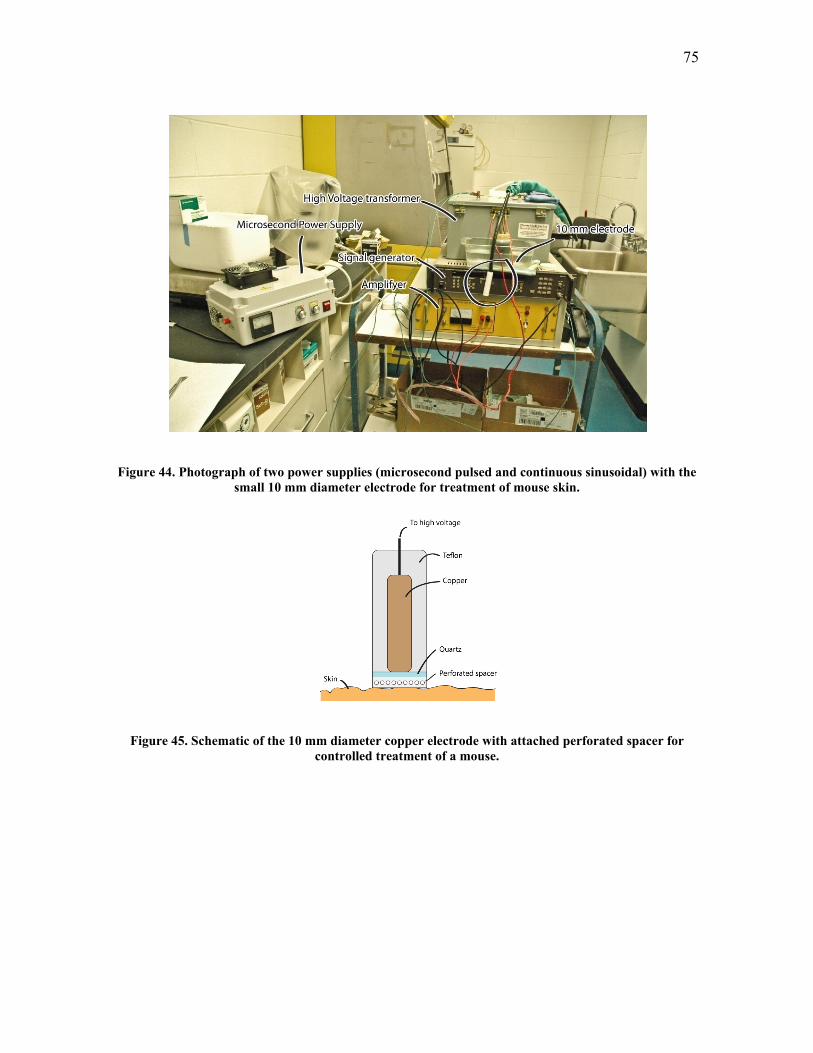
75
Figure 44. Photograph of two power supplies (microsecond pulsed and continuous sinusoidal) with the small 10 mm diameter electrode for treatment of mouse skin.
Figure 45. Schematic of the 10 mm diameter copper electrode with attached perforated spacer for controlled treatment of a mouse.

76
Figure 46. Photograph of an animal immediately following treatment. The perforated spacer is left on the area of treatment to mark it for later sample harvesting. Areas 1 and 2 have already been treated,
in this particular case for 75 seconds at 0.3 Watt/cm2 surface power density by microsecond pulsed power supply. No damage to skin is observed visually.
Based on the experimental matrix, a dose of 10 minutes at 0.6 Watt/cm2 was determined as
maximum acceptable prolonged treatment and a dose of 40 seconds at 2.3 Watt/cm2 was
determined as maximum acceptable high-power treatment. Histological (microscopic)
comparison of control SKH1 skin sample with toxic and non-toxic plasma doses show
regions where plasma dose is high while the animal remains unaffected (Figure 47 –
histological samples, Figure 48 – animal after the treatment). Of note is that sterilization
was achieved at 2 to 4 seconds at high-power treatment of 0.8 ±0.2 Watt/cm2 and at 10
±4.4 seconds at half that power.

77
Figure 47. Histology of toxic and non-toxic to SKH1 skin plasma doses, compared to untreated skin.
Figure 48. Animal remains fine immediately after a high plasma dose (more than 10 times higher than needed for skin sterilization).
To test if the treatment has some longer-term effect which is not immediately visible we
have left a portion of animals alive for up to two weeks. Figure 49 shows the same animal

78
from Figure 48 two weeks following the treatment. There is no apparent visible change to
the treated area and histological samples show no damage to skin as well.
Figure 49. Animal remains fine two weeks following a high plasma dose (more than 10 times higher than needed for skin sterilization).
4.3. Skin Toxicity Trials on Live Regular Swine
Following the toxicity trial on mice we moved on to a large animal model utilizing for it
regular swine. Pig skin resembles closely that of humans and thus makes for a good animal
model of skin toxicity [178, 186-189]. The experimental setup is essentially the same as
for mice, the main difference being that we made a much lighter electrode and taped it to
the animal rather than positioning it using a 3D holder as was done for mice and cadaver
tissue (Figure 50).

79
Figure 50. 3D schematic of the electrode used for swine skin experiments.
The electrode design based on the initial idea shown in Figure 50 has proven to be too
heavy to be held up to animal skin by tape and thus we have removed Teflon coating
replacing it (for electrical safety) with a layer of glue (Figure 51). This small modification
does not change the results this electrode is able to achieve as the plasma remains the
same, but the electrode weight is reduced enough so that it can be securely attached to the
animal skin by tape. This becomes useful mainly for the cases of prolonged treatment (over
30 seconds). This also offers an insight into future electrode designs. When the treatment
will be performed on an actual human patient, especially if he or she is not anesthetized
and is able to move freely, the treatment time needs to be kept below a few seconds for a
hand-held electrode. For treatments longer than that the system needs to be designed to
securely hold the electrode to the patient allowing him or her to move freely while the
skin-to-electrode distance remains fixed.
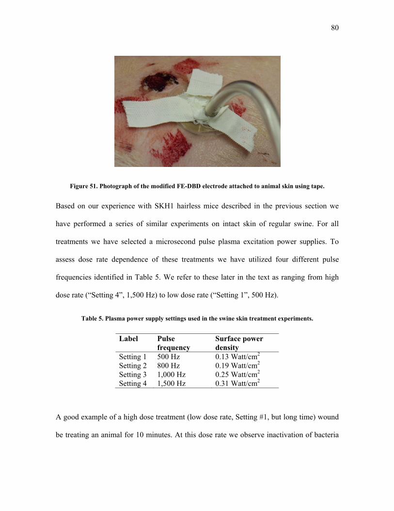
80
Figure 51. Photograph of the modified FE-DBD electrode attached to animal skin using tape.
Based on our experience with SKH1 hairless mice described in the previous section we
have performed a series of similar experiments on intact skin of regular swine. For all
treatments we have selected a microsecond pulse plasma excitation power supplies. To
assess dose rate dependence of these treatments we have utilized four different pulse
frequencies identified in Table 5. We refer to these later in the text as ranging from high
dose rate (“Setting 4”, 1,500 Hz) to low dose rate (“Setting 1”, 500 Hz).
Table 5. Plasma power supply settings used in the swine skin treatment experiments.
Label Pulse frequency
Surface power density
Setting 1 500 Hz 0.13 Watt/cm2 Setting 2 800 Hz 0.19 Watt/cm2 Setting 3 1,000 Hz 0.25 Watt/cm2 Setting 4 1,500 Hz 0.31 Watt/cm2
A good example of a high dose treatment (low dose rate, Setting #1, but long time) wound
be treating an animal for 10 minutes. At this dose rate we observe inactivation of bacteria

81
on agar, human cadaver skin, and on mice in under 10 seconds (5 seconds leads to 7 log
reduction in viable bacteria) [26]. Treatment for longer than 10 seconds would show it to
be not only effective but also safe. We were able to treat animal skin for up to 10 minutes
without any damage to it apart from mild inflammation that disappears within a few
minutes following treatment. For this we locate healthy section of the tissue (Figure 52),
shave it, mark the location where the electrode will be attached, take the electrode to the
tissue and turn on the plasma. Immediately following the treatment we do observe a slight
skin inflammation which can be seen in Figure 52 on the right as compared to Figure 52 on
the left which is a photograph of the same section of the skin but prior to treatment. The
time between these two photographs is approximately 10 minutes and 15 seconds – as soon
as the initial photo is taken the electrode is attached and the plasma treatment commences;
the after treatment photograph is taken a few seconds following the electrode removal, or
as soon as the camera is positioned correctly and focused on the specimen.
Figure 52. Photograph of the animal skin prior (left) and immediately following a 10-minute FE-DBD treatment at low frequency Setting #1 (right). A mild skin inflammation is visible immediately after the

82
treatment (shown) which disappears within a few minutes following the treatment (not shown). Black markings on the skin indicate position of the edge of the treatment electrode (for skin sample
harvesting purposes).
The inflammation we refer to here is barely visible on the photograph while is more
apparent in real life to a human observer directly near the wound. This inflammation
disappears quickly following the treatment. The skin is then harvested and sent for H&E
histological staining and later sectioning following the same protocols as discussed above
for human cadaver and SKH1 mice. Figure 53 shows the result of this staining of the above
skin sample treated for 10 minutes. As can be seen from this image, there is no tissue
damage and/or inflammation; in other words, this skin sample appears the same as an
untreated control sample.
Figure 53. H&E histological stain of the skin sample treated for 10 minutes at low frequency Setting #1 (Figure 52). No microscopic damage to skin can be seen.
The positive control for this treatment is done with the state-of-the-art Bovie® knife which
resistively heats up the tissue by passing current through it causing tissue desiccation,
inflammation which is immediately visible (compare with 10 minutes of plasma treatment

83
in Figure 52), and overall severe tissue damage. Figure 54 shows the result of such a
treatment where excessive damage is clearly seen.
Figure 54. Photograph of the animal skin immediately following treatment by Bovie® knife (positive control) – excessive skin damage, desiccation, and inflammation are clearly visible.
Overall results of the skin toxicity trials on pigs are similar to those on human cadaver skin
and on SKH1 mice – only rather high doses of plasma, those far greater than needed for
sterilization or blood coagulation, are able to damage skin; while doses required to achieve
desired medically relevant therapeutic effect are significantly below the damage threshold.
4.4. Wound Toxicity Trials on Live Regular Swine
One of the potential applications of FE-DBD plasma treatment is sterilization of wounds
and/or coagulation of bleeding capillaries (see end of section 2.2 above). We were able to
test the efficacy and toxicity of such treatment on a superficial partial thickness skin wound
similar to that of scraping one’s knee. Once the animal was anaesthetized the wound was

84
made with a small hand-held dermatome knife (Zimmer, Franklin County, OH, USA)
originally designed to remove precise-thickness skin grafts from a donor patient (Figure
55). Although the hand-held version of this device is difficult to master4 for precise skin
graft removal, the wounds that we were able to create with this blade appear to the eye
closer to the actual wounds that FE-DBD plasma would potentially be treating – they have
a torn texture similar to that of a deep scrape wound one gets falling from a bicycle, for
example (see Figure 55). These are partial thickness wounds with the blade set to cut no
deeper than a millimeter into the skin. This exposes the top layer of skin and breaks
capillaries located in the skin, but not the bigger vessels. Thus, the bleeding is slow and
manageable. The zoom in on the wound demonstrates a typical wound we are able to
induce with this procedure. This is not a severe wound and the bleeding would normally
self-terminate quickly. Immediately after the wound is made we proceed with the selected
treatment.
4 For taking actual skin grafts, Zimmer recommends their automatic knives which are driven by compressed air and have proven themselves to be quite a bit more precise than the hand-held version.

85
Figure 55. Photograph of a process of making a partial thickness skin wound with a dermatome knife (left) and a zoomed in photograph of the resulting wound immediately prior to the FE-DBD plasma
treatment.
Similar to the intact skin, treatment with Bovie® knife quickly coagulates blood and
desiccates the tissue but causes quite significant damage (see Figure 56, left). Although the
wound may be closed, there is a significant level of tissue damage which may prolong the
wound healing process over that if the wound was simply left with no treatment in this
case. While Bovie® electrosurgery knife causes significant tissue damage, FE-DBD
plasma treatment can be applied to the tissue for up to 15 minutes with minimal damage to
this tissue (Figure 56, right), similar to what was observed above with treatment of intact
skin. One other observation is that even after a short treatment, the blood appears to be
coagulated and (although this is not visible on the photograph below) the wound looks to
be covered with a thin layer of clear coagulum. We have seen such a thin transparent cork
formation before with treatment of blood and blood plasma samples [19, 193]. This film
was claimed to be a thin layer of coagulated blood plasma – FE-DBD seems to quickly

86
form a layer of coagulated blood on the surface of the wound which protects the wound
from further external disturbances.
Figure 56. Photograph of a positive control treatment with Bovie® knife (left) where the tissue is clearly desiccated and blood is clotted but the tissue damage is quite extensive. Compared to a
photograph of a wound treated by FE-DBD plasma for 15 minutes in low power Setting #1 (right) where no significant tissue damage is observed and a layer of coagulated blood is formed over the
wound surface.
Results of the various FE-DBD plasma treatments of wound surface are detailed in Table 6
and Table 7, and histological images of these skin samples are shown in Figure 57 and
Figure 58 respectively. The overall observation is that at a low dose rate (Setting #1) we
are able to treat the skin surface for prolonged time periods without seeing significant
tissue damage; while, as expected, at high dose rates we are able to achieve coagulation
and wound closure much faster, along with the tissue damage.
Table 6. Results and analysis of FE-DBD plasma treatment of wound surface.
Label Treatment Group Gross observations during surgical treatment (cm)
Histology analysis (blinded to specimens)
1 Bovie knife (positive control)
2.5 x 1.0 area of effect, eroded
Disruption of epidermis and papillary dermis, areas of

87
dermis coagulated, no dermal nuclei, hair follicles still intact
2 No treatment (negative control)
No change, normal skin No change, normal skin
3 3 min, setting 4 2 x 2 area of effect, mottling
Similar to bovie, burn through to dermis
4 3 min, setting 4 2 x 1.5 area of effect, pigmented, irregular, raised
Similar to bovie, burn through to dermis, slightly more than label 3
5 3 min, setting 3 0.5 x 0.7 area of effect, pigmented
Similar to bovie, burn through to dermis
6 3 min, setting 3 1.5 x 1.5 area of effect, some pigmentation, mottling
Burn through to epidermis, small area of congestion in dermis
7 3 min, setting 2 1.5 x 1.2 area of effect, lightly mottled
Small area of burn in epidermis, most skin here is intact
8 3 min, setting 2 2 x 1.5 area of effect, lightly mottled
Small area of burn in epidermis
9 15 min, setting 1 2.5 x 2 area of effect, lightly mottled
Small area of burn in epidermis
10 15 min, setting 1 2.5 x 3 area of effect, lightly mottled
Small area of burn in epidermis
Ends of 1-10
All edges of the specimens (1-10) to assess for zone effect
No change, normal skin All show normal skin, no zone effect

88
Figure 57. Results of H&E histological stain for samples described in Table 6.
Table 7. Results and analysis of FE-DBD plasma treatment of wound surface.
Label Treatment Group Gross observations during surgical treatment
Histology analysis (blinded to specimens)
1 Bovie Eschar formation, burn formation immediately after treatment Instant blood coagulation Necrotic tissue
Necrosis deep in the dermis. Disruption of the dermis. No dermal nuclei. Hair follicles still intact
1B0 Control wound Normal wound No change to wound 2 High Frequency 3
min Blood clot formation, no necrotic tissue no burn
No damage to dermis. Looks like normal wound. No damage to hair follicles.
3 Low Frequency 3 min
Blood clot formation. No burn
Looks normal. No damage to dermis. Hair follicles intact. Clot formation
4 High Frequency 1 Clot formation. No burn Looks normal. Practically no
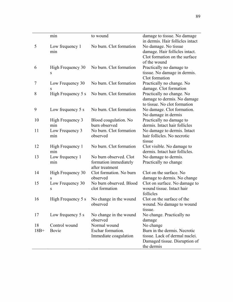
89
min to wound damage to tissue. No damage in dermis. Hair follicles intact
5 Low frequency 1 min
No burn. Clot formation No damage. No tissue damage. Hair follicles intact. Clot formation on the surface of the wound
6 High Frequency 30 s
No burn. Clot formation Practically no damage to tissue. No damage in dermis. Clot formation
7 Low Frequency 30 s
No burn. Clot formation Practically no change. No damage. Clot formation
8 High Frequency 5 s No burn. Clot formation Practically no change. No damage to dermis. No damage to tissue. No clot formation
9 Low frequency 5 s No burn. Clot formation No damage. Clot formation. No damage in dermis
10 High Frequency 3 min
Blood coagulation. No burn observed
Practically no damage to dermis. Intact hair follicles
11 Low Frequency 3 min
No burn. Clot formation observed
No damage to dermis. Intact hair follicles. No necrotic tissue
12 High Frequency 1 min
No burn. Clot formation Clot visible. No damage to dermis. Intact hair follicles.
13 Low frequency 1 min
No burn observed. Clot formation immediately after treatment
No damage to dermis. Practically no change
14 High Frequency 30 s
Clot formation. No burn observed
Clot on the surface. No damage to dermis. No change
15 Low Frequency 30 s
No burn observed. Blood clot formation
Clot on surface. No damage to wound tissue. Intact hair follicles
16 High Frequency 5 s No change in the wound observed
Clot on the surface of the wound. No damage to wound tissue.
17 Low frequency 5 s No change in the wound observed
No change. Practically no damage
18 Control wound Normal wound No change 18B+ Bovie Eschar formation.
Immediate coagulation Burn in the dermis. Necrotic tissue. Lack of dermal nuclei. Damaged tissue. Disruption of the dermis
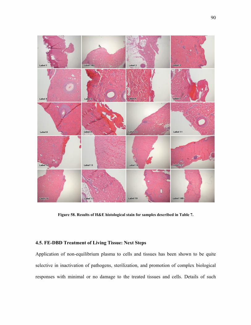
90
Figure 58. Results of H&E histological stain for samples described in Table 7.
4.5. FE-DBD Treatment of Living Tissue: Next Steps
Application of non-equilibrium plasma to cells and tissues has been shown to be quite
selective in inactivation of pathogens, sterilization, and promotion of complex biological
responses with minimal or no damage to the treated tissues and cells. Details of such

91
selectivity with data from many groups around the world are discussed in detail by the
authors in a recent review [26]. Based on our own experimental data presented above with
cadaver tissue, living mice, living pigs, and data reported on previously with cell cultures
of various mammalian cells (macrophages, epithelial cells, b-lymphocytes, fibroblasts, and
melanoma cancer cells) we can thus-far deduce three major hypotheses for the reasons of
the observed selectivity:
1. Metabolism of reactive oxygen species (ROS) is difference in prokaryotic (i.e.
bacteria) and eukaryotic (i.e. mammalian) cells; i.e. while human cells have
protection from species like O (superoxide) bacteria either lack it completely or
the resistance is lower.
2. Higher order organisms have developed more resistance mechanisms to external
stress (osmotic pressure changes, ROS, chemical and biological poisons, etc); in
other words, bacteria usually act as a single cell while mammalian cells, especially
those organized into tissues, communicate with each-other possibly lowering the
effects of the applied poison.
3. Bacterial cells are usually much smaller than mammalian cells and thus have much
higher surface to volume ratio; i.e. simply a lower dose of poison is required to
inactivate same number of bacteria vs. mammalian cells.
These hypotheses are of course quite phenomenological and further detailed testing is
required to claim them to be true. However, authors are continually receiving evidence in
support of these ideas [19, 26, 27, 109, 143, 193-197].

92
Radiation biology studies biological effects of ionizing and non-ionizing radiation of the
whole electromagnetic spectrum. Our concern is primarily with the penetrative ionizing
radiation resulting from radioactivity (alpha, beta, and gamma) and x-rays. Here
radiobiology claims that the main mechanism of action on a cell is through formation of
reactive oxygen species directly in the vicinity of a DNA molecule inside a cell nucleus
[198, 199]. The ROS of interest here are hydroxyl radicals (OH), hydrogen peroxide
(H2O2), and the superoxide anion (O ). A stain for DNA double strand break, the same test
used in radiobiology, shows that the damage does, in fact, occur but is repaired by the cell
rapidly and the cell recovers [200].
FE-DBD plasma used in this treatment is a gas-phase phenomena and is not generally
known to penetrate liquids, unlike radiation does. So, what is it in plasma that is able to go
through liquid? Mechanism of action is likely through same ROS as in radiobiology but
these ROS are not generated at the vicinity of a DNA molecule but rather are transported to
it through a series of mechanisms already present in cells. Example of such a mechanism is
as follows. First, a superoxide anion is generated from hydrated electrons deposited into
the liquid from plasma: e H O O H O O H O . Mammalian cells have a mechanism
of defense against superoxide and immediately converts it into less harmful hydrogen
peroxide through a reaction termed “superoxide dismutation” which is catalyzed by an
enzyme appropriately termed superoxide dismutase (SOD): 2O 2HSOD
H O O .
Hydrogen peroxide can then travel through liquid (and we do see quite high concentrations
of it in liquid cell growth media). At appropriate conditions, hydrogen peroxide is
converted to hydroxyl radicals through a natural reaction chain termed Fenton mechanism

93
(where M+ is any ion coming to liquid from plasma, for example N which is abundant in
air plasma [201]):
H O Fe OH OH Fe
Fe O Fe O
M H O M H O
H O H O H O OH
Hydroxyl radicals may then react with nearby organics leading to chain oxidation and thus
destruction of DNA molecules as well as cellular membranes and other cell components
(here R is some organic molecule):
OH RH R H O
R O RO
RO RH RO H R
Another potential mechanism is through change of ionic force of solution surrounding the
cells by plasma ions. Plasma in this case simply acts as source of excess charges, similar to
adding acid or salt in the vicinity of the cell thus changing osmotic pressure which leads to
pore formation, cell leakage, and possibly death. We can estimate N2+ ion concentration
from ionic flux to the treated surface at the electric plasma specific power of 1 W/cm2:
2
22
16 2219 2
10.3 100eV
W10.3 1100eV cm
ions1 eV10.3 2 10100eV cm sec1.6 10 cm sec
N
N
G
G P
N

94
here Φ is the ion flux, P is specific power, and GN2+ is the “G-factor” for Nitrogen ion
production in electric discharge – number of Nitrogen ion produced per 100 electron-Volt
(eV). In this simplified model, we are assuming that every N2+ ion produced in the plasma
volume reaches the liquid surface. Plasma treatment area is a 2 cm diameter circle so the
treated area is 3.14 cm2. From here we can see that the total number of ions produced per
second is 6*1016. This is an excessively high number but gives us an idea of an order of
magnitude of ions coming to the vicinity of the bacterial cell during treatment. Although
significant further work is needed in this direction, initial indication of a possibility of
influence of ionic force of solution in cell’s lifecycle is apparent and will be further
investigated in the future.

95
CONCLUDING REMARKS
The main novel contributions of this thesis are:
Development of a new non-thermal atmospheric pressure plasma discharge which
can be applied directly to living tissue without painful sensations or visible
damage;
Demonstration of high efficiency of this discharge in deactivation of bacteria on
surfaces of living tissue and those that mimic living tissues;
Demonstration that the discharge parameters related to its uniformity, temperature,
generation of active can be partly controlled via the shape of the applied voltage
waveform;
Demonstration that no visible tissue damage of intact skin and scraped wounds
occurs for discharge doses that are much higher than those required to reduce
bacterial load by over 6 orders of magnitude; and
Demonstration that high efficiency of the direct application of the non-thermal
plasma is mainly due to contact of infected surfaces with charged species in plasma
in the presence of oxygen.
The work carried out in this thesis contributes to the recent trend of using plasma in
medicine not only for tissue ablation or cauterization, but also for much more subtle
modalities of medical therapy. Medical applications of 'cold' plasmas such as tissue
sterilization, treatment of corneal infections, blood coagulation, treatment of cancers,

96
leishmaniasis, treatment of dental diseases and others are in the beginning stages of their
development. Though preliminary results are very promising, bringing 'cold' plasmas into
medical practice will not be very easy. Besides the usual safety concerns, the main obstacle
remains the lack of understanding on molecular and biological levels of mechanisms of
interaction between non-thermal atmospheric pressure plasma and living cells, tissues,
organs, and the whole organism. While it is clear that direct interaction with hot plasma
occurs mainly through heat transfer, interaction with non-thermal plasma in general may
depend on a myriad of variables including various charged species, electric field, UV,
radicals, electronically excited atoms and molecules. Complex synergies may be
responsible for different effects. Not only dose, but the effects of dose rate may be of
critical importance for treatments. Fundamental studies in the area of plasma medicine are
further complicated by the true interdisciplinary nature of investigations that are required.
Although many challenges remain, this work clearly reveals the enormous potential of the
non-thermal plasma technology in medicine. The growth of this technology will probably
continue in the near future not only because the payoffs are substantial, but also because
plasma is one of the few remaining areas of modern technology whose application in
medicine has been barely explored.
97
LIST OF REFERENCES
1. Compton, K.T. and I. Langmuir, Electrical Discharges in Gases. Part I. Survey of Fundamental Processes. Reviews of Modern Physics, 1930. 2(2): p. 123-242.
2. Laroussi, M., D.A. Mendis, and M. Rosenberg, Plasma interaction with microbes. New Journal of Physics, 2003. 5: p. 41.
3. Ginsberg, G.G., A.N. Barkun, J.J. Bosco, J.S. Burdick, G.A. Isenberg, N.L. Nakao, B.T. Petersen, W.B. Silverman, A. Slivka, and P.B. Kelsey, The argon plasma coagulator. Gastrointestinal Endoscopy, 2002. 55(7): p. 807-810.
4. Lord, M.J., J.A. Maltry, and L.M. Shall, Thermal injury resulting from arthroscopic lateral retinacular release by electrocautery: report of three cases and a review of the literature. Arthroscopy, 1991. 7(1): p. 33-7.
5. Vargo, J.J., Clinical applications of the argon plasma coagulator. Gastrointestinal Endoscopy, 2004. 59(1): p. 81-88.
6. Watson, J.P., S. Jowett, K. Oppong, C.O. Record, and K. Matthewson, Colonoscopic argon plasma coagulation for benign and malignant rectal tumours. Gut, 1997. 40: p. Th156-Th156.
7. Colt, H.G. and S.W. Crawford, In vitro study of the safety limits of bronchoscopic argon plasma coagulation in the presence of airway stents. Respirology, 2006. 11(5): p. 643-647.
8. Raiser, J. and M. Zenker, Argon plasma coagulation for open surgical and endoscopic applications: state of the art. Journal of Physics D: Applied Physics, 2006. 39(16): p. 3520.
9. Tremblay, J., Plasma skin regeneration (PSR) in the treatment of acne scars. Journal of the American Academy of Dermatology, 2007. 56(2, Supplement 2): p. AB1.

98
10. Bogle, M.A., K.A. Arndt, and J.S. Dover, Evaluation of plasma skin regeneration technology in low-energy full-facial rejuvenation. Archives of Dermatology, 2007. 143(2): p. 168-174.
11. Kronemyer, B., Portait PSR3 Technology Provides True Skin Regeneration, in European Aesthetic Buyers Guide. Spring 2006.
12. Coulombe, S., V. Leveille, S. Yonson, and R.L. Leask, Miniature atmospheric pressure glow discharge torch (APGD-t) for local biomedical applications. Pure and Applied Chemistry, 2006. 78(6): p. 1147-1156.
13. Leveille, V. and S. Coulombe, Design and preliminary characterization of a miniature pulsed RF APGD torch with downstream injection of the source of reactive species. Plasma Sources Science and Technology, 2005. 14(3): p. 467(10).
14. Coulombe, S. Live cell permeabilization using the APGD-t. in First International Conference on Plasma Medicine (ICPM-1). 2007. Corpus Christi, Texas.
15. Kieft, I., D. Darios, A. Roks, and E. Stoffels, Plasma treatment of mammalian vascular cells: A quantitative description. Plasma Science, IEEE Transactions on, 2005. 33(2): p. 771-775.
16. Kieft, I.E., M. Kurdi, and E. Stoffels, Reattachment and Apoptosis After Plasma-Needle Treatment of Cultured Cells. Plasma Science, IEEE Transactions on, 2006. 34(4): p. 1331-1336.
17. Stoffels, E., Gas plasmas in biology and medicine. Journal of Physics D: Applied Physics, 2006. 39(16).
18. Stoffels, E., I. Kieft, R. Sladek, L. Bedem, E. Laan, and M. Steinbuch, Plasma needle for in vivo medical treatment: recent developments and perspectives. Plasma Sources Science and Technology, 2006. 15(4): p. S169.
19. Fridman, G., M. Peddinghaus, H. Ayan, A. Fridman, M. Balasubramanian, A. Gutsol, A. Brooks, and G. Friedman, Blood coagulation and living tissue sterilization by floating-electrode dielectric barrier discharge in air. Plasma Chemistry and Plasma Processing, 2006. 26(4): p. 425-442.

99
20. Fridman, G., A. Shereshevsky, M. Peddinghaus, A. Gutsol, V. Vasilets, A. Brooks, M. Balasubramanian, G. Friedman, and A. Fridman. Bio-Medical Applications of Non-Thermal Atmospheric Pressure Plasma. in 37th AIAA Plasmadynamics and Lasers Conference. 2006. San Francisco, California.
21. Shekhter, A.B., V.A. Serezhenkov, T.G. Rudenko, A.V. Pekshev, and A.F. Vanin, Beneficial effect of gaseous nitric oxide on the healing of skin wounds. Nitric Oxide-Biology and Chemistry, 2005. 12(4): p. 210-219.
22. Gostev, V. and D. Dobrynin. Medical microplasmatron. in 3rd International Workshop on Microplasmas (IWM-2006). 2006. Greifswald, Germany.
23. Gostev, V., Cold Plasma in Biological Investigations, in NATO Advanced Study Institute (ASI): Plasma Assisted Decontamination of Biological and Chemical Agents. 2007: Çeşme, Turkey.
24. Fridman, A., A. Chirokov, and A. Gutsol, Non-thermal atmospheric pressure discharges. Journal of Physics D: Applied Physics, 2005. 38(2): p. R1-R24.
25. Laroussi, M., I. Alexeff, and W.L. Kang, Biological decontamination by nonthermal plasmas. Plasma Science, IEEE Transactions on, 2000. 28(1): p. 184-188.
26. Fridman, G., A.B. Shekhter, V.N. Vasilets, G. Friedman, A. Gutsol, and A. Fridman, Applied Plasma Medicine. Plasma Processes and Polymers, 2008. 5(6): p. 503-533.
27. Fridman, G., A.D. Brooks, M. Balasubramanian, A. Fridman, A. Gutsol, V.N. Vasilets, H. Ayan, and G. Friedman, Comparison of Direct and Indirect Effects of Non-Thermal Atmospheric Pressure Plasma on Bacteria. Plasma Processes and Polymers, 2007. 4: p. 370-375.
28. Rutala, W.A., M.M. Stiegel, and F.A. Sarubbi, Decontamination of laboratory microbiological waste by steam sterilization. Applied and Environmental Microbiology, 1982. 43(6): p. 1311-1316.
29. Lemieux, P., R. Sieber, A. Osborne, and A. Woodard, Destruction of Spores on Building Decontamination Residue in a Commercial Autoclave? Applied and Environmental Microbiology, 2006. 72(12): p. 7687-7693.
100
30. Sheldrake, M.A., C.D. Majors, D.J. Gaines, and C.J. Palenik, Effectiveness of three types of sterilization on the contents of sharps containers. Quintessence Int, 1995. 26(11): p. 771-8.
31. Palenik, C.J., M.L. Adams, and C.H. Miller, Effectiveness of steam autoclaving on the contents of sharps containers. Am J Dent, 1990. 3(6): p. 239-44.
32. Prolo, D.J., P.W. Pedrotti, and D.H. White, Ethylene oxide sterilization of bone, dura mater, and fascia lata for human transplantation. Journal Article Neurosurgery. 6 (5): 529-39, May 1980. Neurosurgery, 1980. 6(5): p. 529-39.
33. Gilbert, G.L., V.M. Gambill, D.R. Spiner, R.K. Hoffman, and C.R. Phillips, Effect of Moisture on Ethylene Oxide Sterilization 1. Applied and Environmental Microbiology, 1964. 12(6): p. 496-503.
34. Ohmi, T., T. Isagawa, T. Imaoka, and I. Sugiyama, Ozone Decomposition in Ultrapure Water and Continuous Ozone Sterilization for a Semiconductor Ultrapure Water System. Journal of The Electrochemical Society, 1992. 139: p. 3336.
35. Burleson, G.R., T.M. Murray, and M. Pollard, Inactivation of Viruses and Bacteria by Ozone, With and Without Sonication. Applied and Environmental Microbiology, 1975. 29(3): p. 340-344.
36. Jeng, D.K. and A.G. Woodworth, Chlorine Dioxide Gas Sterilization under Square-Wave Conditions. Applied and Environmental Microbiology, 1990. 56(2): p. 514-519.
37. Dennis Jr, M.B., D.R. Jones, and F.C. Tenover, Chlorine dioxide sterilization of implanted right atrial catheters in rabbits. Lab Anim Sci, 1989. 39(1): p. 51-5.
38. Moisan, M., J. Barbeau, S. Moreau, J. Pelletier, M. Tabrizian, and L.H. Yahia, Low-temperature sterilization using gas plasmas: a review of the experiments and an analysis of the inactivation mechanisms. International Journal of Pharmaceutics, 2001. 226(1-2): p. 1-21.
39. Lerouge, S., M.R. Wertheimer, and L.H. Yahia, Plasma Sterilization: A Review of Parameters, Mechanisms, and Limitations. Plasmas and Polymers, 2001. 6(3): p. 175-188.

101
40. Laroussi, M., I. Alexeff, J.P. Richardson, and F.F. Dyer, The resistive barrier discharge. IEEE Transactions on Plasma Science, 2002. 30(1): p. 158-159.
41. Thiyagarajan, M., I. Alexeff, S. Parameswaran, and S. Beebe, Atmospheric pressure resistive barrier cold plasma for biological decontamination. IEEE Transactions on Plasma Science, 2005. 33(2): p. 322-323.
42. Laroussi, M., Nonthermal decontamination of biological media by atmospheric-pressure plasmas: Review, analysis, and prospects. Plasma Science, IEEE Transactions on, 2002. 30(4): p. 1409-1415.
43. Laroussi, M. and F. Leipold, Evaluation of the roles of reactive species, heat, and UV radiation in the inactivation of bacterial cells by air plasmas at atmospheric pressure. International Journal of Mass Spectrometry, 2004. 233(1-3): p. 81-86.
44. Laroussi, M., O. Minayeva, F.C. Dobbs, and J. Woods, Spores Survivability After Exposure to Low-Temperature Plasmas. Plasma Science, IEEE Transactions on, 2006. 34(4): p. 1253-1256.
45. Lu, X.P. and M. Laroussi, Optimization of ultraviolet emission and chemical species generation from a pulsed dielectric barrier discharge at atmospheric pressure. Journal of Applied Physics, 2005. 98(2).
46. Lu, X.P. and M. Laroussi, Temporal and spatial emission behaviour of homogeneous dielectric barrier discharge driven by unipolar sub-microsecond square pulses. Journal of Physics D-Applied Physics, 2006. 39(6): p. 1127-1131.
47. Laroussi, M. and X. Lu, Room-temperature atmospheric pressure plasma plume for biomedical applications. Applied Physics Letters, 2005. 87(11).
48. Lu, X.P. and M. Laroussi, Dynamics of an atmospheric pressure plasma plume generated by submicrosecond voltage pulses. Journal of Applied Physics, 2006. 100(6): p. 063302-6.
49. Laroussi, M., X.P. Lu, and C.M. Malott, A non-equilibrium diffuse discharge in atmospheric pressure air. Plasma Sources Science & Technology, 2003. 12(1): p. 53-56.
102
50. Lu, X.P. and M. Laroussi, Atmospheric pressure glow discharge in air using a water electrode. IEEE Transactions on Plasma Science, 2005. 33(2): p. 272-273.
51. Boudam, M.K., M. Moisan, B. Saoudi, C. Popovici, N. Gherardi, and F. Massines, Bacterial spore inactivation by atmospheric-pressure plasmas in the presence or absence of UV photons as obtained with the same gas mixture. Journal of Physics D: Applied Physics, 2006. 39(16): p. 3494.
52. Massines, F., N. Gherardi, N. Naude, and P. Segur, Glow and Townsend dielectric barrier discharge in various atmosphere. Plasma Physics and Controlled Fusion, 2005. 47: p. B577-B588.
53. Massines, F., A. Rabehi, P. Decomps, R.B. Gadri, P. Segur, and C. Mayoux, Experimental and theoretical study of a glow discharge at atmospheric pressure controlled by dielectric barrier. Journal of Applied Physics, 1998. 83(6): p. 2950-2957.
54. Becker, K., A. Koutsospyros, S.M. Yin, C. Christodoulatos, N. Abramzon, J.C. Joaquin, and G. Brelles-Marino, Environmental and biological applications of microplasmas. Plasma Physics and Controlled Fusion, 2005. 47: p. B513-B523.
55. Becker, K.H., K.H. Schoenbach, and J.G. Eden, Microplasmas and applications. Journal of Physics D-Applied Physics, 2006. 39(3): p. R55-R70.
56. Ben Gadri, R., J.R. Roth, T.C. Montie, K. Kelly-Wintenberg, P.P.Y. Tsai, D.J. Helfritch, P. Feldman, D.M. Sherman, F. Karakaya, and Z.Y. Chen, Sterilization and plasma processing of room temperature surfaces with a one atmosphere uniform glow discharge plasma (OAUGDP). Surface & Coatings Technology, 2000. 131(1-3): p. 528-542.
57. Kelly-Wintenberg, K., A. Hodge, T.C. Montie, L. Deleanu, D. Sherman, J.R. Roth, P. Tsai, and L. Wadsworth, Use of a one atmosphere uniform glow discharge plasma to kill a broad spectrum of microorganisms. Journal of Vacuum Science & Technology a-Vacuum Surfaces and Films, 1999. 17(4): p. 1539-1544.
58. Kelly-Wintenberg, K., D.M. Sherman, P.P.Y. Tsai, R.B. Gadri, F. Karakaya, C. Zhiyu, J.R. Roth, and T.C. Montie, Air filter sterilization using a one atmosphere

103
uniform glow discharge plasma (the volfilter). Plasma Science, IEEE Transactions on, 2000. 28(1): p. 64-71.
59. Montie, T.C., K. Kelly-Wintenberg, and J.R. Roth, An overview of research using the one atmosphere uniform glow discharge plasma (OAUGDP) for sterilization of surfaces and materials. Plasma Science, IEEE Transactions on, 2000. 28(1): p. 41-50.
60. Roth, J.R., S. Nourgostar, and T.A. Bonds, The one atmosphere uniform glow discharge plasma (OAUGDP) - A platform technology for the 21st century. IEEE Transactions on Plasma Science, 2007. 35(2): p. 233-250.
61. Roth, J.R., J. Rahel, X. Dai, and D.M. Sherman, The physics and phenomenology of one atmosphere uniform glow discharge plasma (OAUGDP (TM)) reactors for surface treatment applications. Journal of Physics D-Applied Physics, 2005. 38(4): p. 555-567.
62. Roth, J.R., D.M. Sherman, R.B. Gadri, F. Karakaya, C. Zhiyu, T.C. Montie, K. Kelly-Wintenberg, and P.P.Y. Tsai, A remote exposure reactor (RER) for plasma processing and sterilization by plasma active species at one atmosphere. Plasma Science, IEEE Transactions on, 2000. 28(1): p. 56-63.
63. Redlich, C.A., J. Sparer, and M.R. Cullen, Sick-building syndrome. The Lancet, 1997. 349(9057): p. 1013-1016.
64. Chalise, P.R., S. Perni, G. Shama, B.M. Novac, I.R. Smith, and M.G. Kong, Lethality mechanisms in Escherichia coli induced by intense sub-microsecond electrical pulses. Applied Physics Letters, 2006. 89(15).
65. Deng, X., J. Shi, and M.G. Kong, Physical Mechanisms of Inactivation of Bacillus subtilis Spores Using Cold Atmospheric Plasmas. Plasma Science, IEEE Transactions on, 2006. 34(4): p. 1310-1316.
66. Deng, X.T., J.J. Shi, H.L. Chen, and M.G. Kong, Protein destruction by atmospheric pressure glow discharges. Applied Physics Letters, 2007. 90(1).

104
67. Deng, X.T., J.J. Shi, and M.G. Kong, Protein destruction by a helium atmospheric pressure glow discharge: Capability and mechanisms. Journal of Applied Physics, 2007. 101(7).
68. Nie, Q.Y., C.S. Ren, D.Z. Wang, S.Z. Li, J.L. Zhang, and M.G. Kong, Self-organized pattern formation of an atmospheric pressure plasma jet in a dielectric barrier discharge configuration. Applied Physics Letters, 2007. 90(22).
69. Perni, S., X.T. Deng, G. Shama, and M.G. Kong, Modeling the Inactivation Kinetics of Bacillus subtilis Spores by Nonthermal Plasmas. Plasma Science, IEEE Transactions on, 2006. 34(4): p. 1297-1303.
70. Perni, S., G. Shama, J.L. Hobman, P.A. Lund, C.J. Kershaw, G.A. Hidalgo-Arroyo, C.W. Penn, X.T. Deng, J.L. Walsh, and M.G. Kong, Probing bactericidal mechanisms induced by cold atmospheric plasmas with Escherichia coli mutants. Applied Physics Letters, 2007. 90(7).
71. Shi, J., D. Liu, and M. Kong, Effects of dielectric barriers in radio frequency atmospheric glow discharges. IEEE Transactions on Plasma Science, 2007. 35(2): p. 137-142.
72. Vleugels, M., G. Shama, X.T. Deng, E. Greenacre, T. Brocklehurst, and M.G. Kong, Atmospheric plasma inactivation of biofilm-forming bacteria for food safety control. Plasma Science, IEEE Transactions on, 2005. 33(2): p. 824-828.
73. Walsh, J.L. and M.G. Kong, Sharp bursts of high-flux reactive species in submicrosecond atmospheric pressure glow discharges. Applied Physics Letters, 2006. 89(23).
74. Walsh, J.L., J.J. Shi, and M.G. Kong, Contrasting characteristics of pulsed and sinusoidal cold atmospheric plasma jets. Applied Physics Letters, 2006. 88: p. 171501.
75. Glover, J., P. Bendick, and W. Link, The use of thermal knives in surgery: electrosurgery, lasers, plasma scalpel. Curr Probl Surg., 1978. 15(1): p. 1-78.
76. Shekhter, A.B., R.K. Kabisov, A.V. Pekshev, N.P. Kozlov, and Y.L. Perov, Experimental and clinical validation of plasmadynamic therapy of wounds with

105
nitric oxide. Bulletin of Experimental Biology and Medicine, 1998. 126(2): p. 829-834.
77. Pekshev, A.V., Use of a novel biological factor - exogenic nitrogen oxide - in surgical treatment of paradontitis. Stomatology, 2001. 1: p. 80-83.
78. Furchgott, R.F., Endothelium-Derived Relaxing Factor: Discovery, Early Studies, and Identifcation as Nitric Oxide (Nobel Lecture). Angewandte Chemie International Edition, 1999. 38(13-14): p. 1870-1880.
79. Shulutko, A.M., N.V. Antropova, and Y.A. Kryuger, No-therapy in the treatment of purulent and necrotic lesions of lower extremities in diabetic patients. Surgery, 2004. 12: p. 43-46.
80. Seeger, W., Pneumology - From phthisiology to regenerative medicine. Deutsche Medizinische Wochenschrift, 2005. 130(25-26): p. 1543-1546.
81. Efimenko, N.A., V.I. Hrupkin, L.A. Marahonich, V.I. Iashenko, V.I. Moskalenko, and E.V. Lykianenko, Air-Plasma Flows and NO-therapy - a Novel Technology in a Clinical Setting of the Military Treatment and Profilactic Facilities (Experimental and Clinical Study). Journal of Military Medicine (Voenno-Meditsinskii Jurnal), 2005. 5: p. 51-54.
82. Davydov, A.I., S.T. Kuchukhidze, A.B. Shekhter, A.G. Khanin, A.V. Pekshev, and V.V. Pankratov, Clinical evaluation of intraoperative application of air-plasma flow enriched by nitrogen monoxide in operations on the uterus and adnexa. Problems of Gynecology, Obstetrics and Perinatology, 2004. 3(4): p. 12-17.
83. Davydov, A.I., A.N. Strijakov, A.V. Pekshev, S.T. Kuchukhidze, and I.A. Klihdukhov, Possibilities and prospectives in plasma endosurgery with generation of nitrogen monoxide in vaginal surgeries. Questions in Obstetrics and Gynaecology (OB/GYN), 2002. 1(2): p. 57-60.
84. Kuchukhidze, S.T., I.A. Klihdukhov, K.R. Bakhtiarov, and V.V. Pankratov, High energy applications in modern gynaecology Questions in Obstetrics and Gynaecology (OB/GYN), 2004. 3(2): p. 76-82.

106
85. Grigoryan, A.S., A.I. Grudyanov, O.A. Frolova, Z.P. Antipova, A.I. Yerokhin, A.B. Shekhter, and A.V. Pekshev, New biological factor, exogenous nitrogen oxide, in treatment of chronic periodontitis. Stomatology, 2001(1): p. 80-83.
86. Chesnokova, N.V., R.A. Gundorova, O.I. Krvasha, V.P. Bakov, and N.G. Davydova, Experimental investigation of the influence of gas flow containing nitrogen oxide in treatment of corneal wounds. Vestnik RAMN, 2003. 5: p. 40-44.
87. Golubovskii, G.A., V.G. Zenger, A.N. Nasedkin, E.I. Prokofieva, and A.A. Borojtsov. Use of exogenic NO-therapy in regenerative surgery of bronchial tubes. in IV'th Army Medical Conference on Intensive Therapy and Profilactic Treatments of Surgical Infections. 2004. Moscow, Russia.
88. Zaitsev, V.M., Comparative analysis of effectiveness of treatment of chronic supporated ulcers by NO-therapy with addition of ultrasound implantation of miramistine with treatment by ultrasound implantation alone. Russian Journal of Otorinolaringology, 2003. 1: p. 58-59.
89. Chernekhovskaia, N.E., V.K. Shishlo, B.D. Svistunov, and A.S. Svitunova. Intra-bronchial NO-therapy in treatment of wound complications in tuberculosis patients. in IV'th Army Medical Conference on Intensive Therapy and Profilactic Treatments of Surgical Infections. 2004. Moscow, Russia.
90. Misyn, F., E. Besedin, V. Gostev, and О. Komkova. Experimental studying of bactericidal action of cold plasma. in Diagnostics and treatment of infectious diseases. 2000. Petrozavodsk, Russia.
91. Misyn, F.A., E.V. Besedin, O.P. Komkova, and V.A. Gostev. Experimental investigation of bactericidal influence of “cold” plasma and its interaction with cornea. in Diagnostics and treatment of infectious diseases. 2000. Petrozavodsk, Russia.
92. Misyn, F.A., E.V. Besedin, A.M. Obraztsova, and V.A. Gostev. Experimental curing of bacterial ulcerous keratitis with “cold” plasma. in Diagnostics and treatment of infectious diseases. 2000. Petrozavodsk, Russia.

107
93. Misyn, F.A. and V.A. Gostev. ”Cold” plasma application in eyelid phlegmon curing. in Diagnostics and treatment of infectious diseases. 2000. Petrozavodsk, Russia.
94. Choudhuri, M., R. McQueen, S. Inoue, and R.C. Gordon, Efficiency of skin sterilization for a venipuncture with the use of commercially available alcohol or iodine pads. Am J Infect Control, 1990. 18(2): p. 82-5.
95. Laan, E., E. Stoffels, and M. Steinbuch, Development of a smart positioning sensor for the plasma needle. Plasma Sources Science and Technology, 2006. 15(3): p. 582.
96. Kieft, I.E., E.P. Laan, and E. Stoffels, Electrical and optical characterization of the plasma needle. New Journal of Physics, 2004. 6(1): p. 149.
97. Stoffels, E., A.J. Flikweert, W.W. Stoffels, and G.M.W. Kroesen, Plasma needle: a non-destructive atmospheric plasma source for fine surface treatment of (bio)materials. Plasma Sources Science and Technology, 2002. 11(4): p. 383-388.
98. Stoffels, E. Cold atmospheric plasma for wound healing: in vitro assessment. in First International Conference on Plasma Medicine (ICPM-1). 2007. Corpus Christi, Texas.
99. Kieft, I.E., J.L.V. Broers, V. Caubet-Hilloutou, D.W. Slaaf, F.C.S. Ramaekers, and E. Stoffels, Electric discharge plasmas influence attachment of cultured CHO k1 cells. Bioelectromagnetics, 2004. 25(5): p. 362-368.
100. Kieft, I.E., D. Darios, A.J.M. Roks, and E. Stoffels, Plasma treatment of mammalian vascular cells: A quantitative description. IEEE Transactions on Plasma Science, 2005. 33(2): p. 771-775.
101. Kieft, I.E., N.A. Dvinskikh, J.L.V. Broers, D.W. Slaaf, and E. Stoffels, Effect of plasma needle on cultured cells [5483-31]. Proceedings of SPIE, 2004. 5483: p. 247-251.
102. Sladek, R.E.J., E. Stoffels, R. Walraven, P.J.A. Tielbeek, and R.A. Koolhoven, Plasma treatment of dental cavities: A feasibility study. Plasma Science, IEEE Transactions on, 2004. 32(4): p. 1540-1543.
108
103. Sladek, R.E.J. and E. Stoffels, Deactivation of Escherichia coli by the plasma needle. Journal of Physics D: Applied Physics, 2005. 38(11): p. 1716-1721.
104. Pompl, R., T. Shimizu, H.U. Schmidt, W. Bunk, F. Jamitzky, B. Steffes, K. Ramrath, B. Peters, W. Stolz, T. Urayama, R. Ramasamy, S. Fujii, and G.E. Morfill. Efficiency and Medical Compatibility of Low-Temperature Plasma Sterilization. in 6th Int. Conf. Reactive Plasmas. 2006. Matsushima, Japan.
105. Shimizu, T., B. Steffes, R. Pompl, F. Jamitzky, W. Bunk, K. Ramrath, B. Peters, W. Stolz, H.U. Schmidt, T. Urayama, K. Fujioka, R. Ramasamy, S. Fujii, and G.E. Morfill. Microwave Plasma Torch for Bacterial Sterilization. in 6th Int. Conf. Reactive Plasmas. 2006. Matsushima, Japan.
106. Elaine L. Chao, S., Controlling Electrical Hazards, OSHA 3075, U.S.D.o. Labor, Editor. 2002 (Revised).
107. Bayrashev, A. and B. Ziaie, Silicon wafer bonding through RF dielectric heating. Sensors & Actuators: A. Physical, 2003. 103(1-2): p. 16-22.
108. Ikediala, J., J. Hansen, J. Tang, S. Drake, and S. Wang, Development of saline-water-immersion technique with RF energy as a postharvest treatment against codling moth in cherries. Postharvest Biology and Technology, 2002. 24(2): p. 209-221.
109. Cooper, M., Y. Yang, D. Dobrynin, H. Ayan, A. Fridman, A. Gutsol, V. Vasilets, and G. Fridman, Observations of Filament Behavior and Plasma Uniformity in Continuous and Pulsed Dielectric Barrier Discharges, in Drexel University Ninth Annual Research Innovation Scholarship and Creativity (RISC) Day. 2007: Philadelphia, USA.
110. Cooper, M., Y. Yang, G. Fridman, H. Ayan, V.N. Vasilets, A. Gutsol, G. Friedman, and A. Fridman. Uniform and Filamentary Nature of Continuous-Wave and Pulsed Dielectric Barrier Discharge Plasma. in NATO Advanced Study Institute on Plasma Assisted Decontamination of Biological and Chemical Agents. 2007. Cesme-Izmir, Turkey: Springer.
111. Dee Unglaub Silverthorn, W.C.O., Claire W. Garrison, Andrew C. Silverthorn, Bruce R. Johnson, Human Physiology, an Integrated Approach. 3rd ed. 2004: Benjamin-Cummings Publishing Company. 912.
109
112. Henry, J.B., Clinical Diagnosis and Management by Laboratory Methods. 20 ed. 2001: W.B. Saunders Company. 1512.
113. Cheng, C., P. Liu, L. Xu, L. Zhang, R. Zhan, and W. Zhang, Development of a new atmospheric pressure cold plasma jet generator and application in sterilization. Chinese Physics, 2006. 15(7): p. 1544.
114. Herbold, K., B. Flehmig, and K. Botzenhart, Ozone application for sterilization. Appl Enviromental Microbiology, 1989. 11: p. 2949-2953.
115. Sharma, A., A. Pruden, O. Stan, and G.J. Collins, Bacterial Inactivation Using an RF-Powered Atmospheric Pressure Plasma. Plasma Science, IEEE Transactions on, 2006. 34(4): p. 1290-1296.
116. Abramzon, N., J.C. Joaquin, J. Bray, and G. Brelles-Marino, Biofilm Destruction by RF High-Pressure Cold Plasma Jet. Plasma Science, IEEE Transactions on, 2006. 34(4): p. 1304-1309.
117. Efremov, N.M., B.Y. Adamiak, V.I. Blouchin, S.J. Dadashev, K.J. Dmitriev, O.P. Gryaznova, and V.F. Jusbashev, Action of a self-sustained glow discharge in atmospheric pressure air on biological objects. Plasma Science, IEEE Transactions on, 2000. 28(1): p. 238-241.
118. Stoffels, E., Biomedical applications of electric gas discharge. High Temperature Material Processes, 2000. 5(2): p. 191-202.
119. Chu, P.K., J.Y. Chen, L.P. Wang, and N. Huang, Plasma-surface modification of biomaterials. Materials Science & Engineering R-Reports, 2002. 36(5-6): p. 143-206.
120. Zhang, R., L. Wang, Y. Wu, Z. Guan, and Z. Jia, Bacterial Decontamination of Water by Bipolar Pulsed Discharge in a Gas-Liquid-Solid Three-Phase Discharge Reactor. Plasma Science, IEEE Transactions on, 2006. 34(4): p. 1370-1374.
121. Tarasenko, O., S. Nourbakhsh, S.P. Kuo, A. Bakhtina, P. Alusta, D. Kudasheva, M. Cowman, and K. Levon, Scanning Electron and Atomic Force Microscopy to Study Plasma Torch Effects on B. cereus Spores. Plasma Science, IEEE Transactions on, 2006. 34(4): p. 1281-1289.

110
122. Soloshenko, I.A., V.Y. Bazhenov, V.A. Khomich, V.V. Tsiolko, and N.G. Potapchenko, Comparative Research of Efficiency of Water Decontamination by UV Radiation of Cold Hollow Cathode Discharge Plasma Versus That of Low- and Medium-Pressure Mercury Lamps. Plasma Science, IEEE Transactions on, 2006. 34(4): p. 1365-1369.
123. Sladek, R.E.J., T.A. Baede, and E. Stoffels, Plasma-Needle Treatment of Substrates With Respect to Wettability and Growth of Escherichia coli and Streptococcus mutans. Plasma Science, IEEE Transactions on, 2006. 34(4): p. 1325-1330.
124. Sarra-Bournet, C., S. Turgeon, D. Mantovani, and G. Laroche, A study of atmospheric pressure plasma discharges for surface functionalization of PTFE used in biomedical applications. Journal of Physics D: Applied Physics, 2006. 39(16): p. 3461.
125. Sakiyama, Y. and D.B. Graves, Finite element analysis of an atmospheric pressure RF-excited plasma needle. Journal of Physics D: Applied Physics, 2006. 39(16): p. 3451.
126. Narsetti, R., R.D. Curry, K.F. McDonald, T.E. Clevenger, and L.M. Nichols, Microbial Inactivation in Water Using Pulsed Electric Fields and Magnetic Pulse Compressor Technology. Plasma Science, IEEE Transactions on, 2006. 34(4): p. 1386-1393.
127. Kuo, S.P., O. Tarasenko, S. Popovic, and K. Levon, Killing of Bacterial Spores Contained in a Paper Envelope by a Microwave Plasma Torch. Plasma Science, IEEE Transactions on, 2006. 34(4): p. 1275-1280.
128. Cvelbar, U., D. Vujosevic, Z. Vratnica, and M. Mozetic, The influence of substrate material on bacteria sterilization in an oxygen plasma glow discharge. Journal of Physics D: Applied Physics, 2006. 39(16): p. 3487.
129. Goree, J., B. Liu, D. Drake, and E. Stoffels, Killing of S. mutans Bacteria Using a Plasma Needle at Atmospheric Pressure. Plasma Science, IEEE Transactions on, 2006. 34(4): p. 1317-1324.

111
130. Gaunt, L.F., C.B. Beggs, and G.E. Georghiou, Bactericidal Action of the Reactive Species Produced by Gas-Discharge Nonthermal Plasma at Atmospheric Pressure: A Review. Plasma Science, IEEE Transactions on, 2006. 34(4): p. 1257-1269.
131. Moisan, M., J. Barbeau, J. Pelletier, and B. Saoudi, Low-pressure cold plasma sterilization at atmospheric pressure. Vide-Science Technique Et Applications, 2002. 57(303): p. 71.
132. Krishnamurthy, K., A. Demirci, and J. Irudayaraj, Inactivation of Staphylocloccus aureus by pulsed UV-light sterilization. Journal of Food Protection, 2004. 67(5): p. 1027-1030.
133. Sosnin, E.A., E. Stoffels, M.V. Erofeev, I.E. Kieft, and S.E. Kunts, The effects of UV irradiation and gas plasma treatment on living mammalian cells and bacteria: A comparative approach. Plasma Science, IEEE Transactions on, 2004. 32(4): p. 1544-1550.
134. Erofeev, M.V., I.E. Kieft, E.A. Sosnin, and E. Stoffels, UV Excimer Lamp Irradiation of Fibroblasts: The Influence on Antioxidant Homeostasis. Plasma Science, IEEE Transactions on, 2006. 34(4): p. 1359-1364.
135. Craik, S.A., D. Weldon, G.R. Finch, J.R. Bolton, and M. Belosevic, Inactivation of Cryptosporidium parvum oocysts using medium- and low-pressure ultraviolet radiation. Water Research, 2001. 35(6): p. 1387-1398.
136. Stoffels, E., I.E. Kieft, R.E. Sladek, E.P. van der Laan, and D.W. Slaaf, Gas plasma treatment: a new approach to surgery? Crit Rev Biomed Eng, 2004. 32(5-6): p. 427-60.
137. Stoffels, E., I.E. Kieft, and R.E.J. Sladek, Superficial treatment of mammalian cells using plasma needle. Journal of Physics D Applied Physics, 2003. 36(23): p. 2908-2913.
138. Stoffels, E., R.E.J. Sladek, and I.E. Kieft, Gas Plasma Effects on Living Cells. Physica Scripta, 2004. 107: p. 79.
139. Laroussi, M., C. Tendero, X. Lu, S. Alla, and W.L. Hynes, Inactivation of Bacteria by the Plasma Pencil. Plasma Processes and Polymers, 2006. 3(6-7): p. 470-473.

112
140. Leveille, V. and S. Coulombe, Atomic oxygen production and exploration of reaction mechanisms in a He-O-2 atmospheric pressure glow discharge torch. Plasma Processes and Polymers, 2006. 3(8): p. 587-596.
141. Yonson, S., S. Coulombe, V. Leveille, and R.L. Leask, Cell treatment and surface functionalization using a miniature atmospheric pressure glow discharge plasma torch. Journal of Physics D-Applied Physics, 2006. 39(16): p. 3508-3513.
142. Leveille, V. and S. Coulombe, Design and preliminary characterization of a miniature pulsed RF APGD torch with downstream injection of the source of reactive species. Plasma Sources Science & Technology, 2005. 14(3): p. 467-476.
143. Ayan, H., G. Fridman, D. Staack, A. Gutsol, V. Vasilets, A. Fridman, and G. Friedman, Heating effect of dielectric barrier discharges in direct medical treatment. IEEE Transactions on Plasma Science, 2007(submitted).
144. Schoenbach, K., R. Barker, and S. Liu, Special issue on nonthermal medical/biological treatments using electromagnetic fields and ionized gases. Plasma Science, IEEE Transactions on, 2000. 28(1): p. 2-5.
145. Kotov, Y.A. and S.Y. Sokovnin, Overview of the application of nanosecond electron beams for radiochemical sterilization. Plasma Science, IEEE Transactions on, 2000. 28(1): p. 133-136.
146. Kolb, J.F., M.G. Kong, and P.F. Blackmore, Special Issue on Nonthermal Medical/Biological Applications Using Ionized Gases and Electromagnetic Fields. Plasma Science, IEEE Transactions on, 2006. 34(4): p. 1250-1252.
147. Chirokov, A., A. Gutsol, A. Fridman, K. Sieber, J. Grace, and K. Robinson, Self-organization of microdischarges in dielectric barrier discharge plasma. Plasma Science, IEEE Transactions on, 2005. 33(2): p. 300-301.
148. Chirokov, A., A. Gutsol, A. Fridman, K.D. Sieber, J.M. Grace, and K.S. Robinson, Analysis of two-dimensional microdischarge distribution in dielectric-barrier discharges. Plasma Sources Science and Technology, 2004. 13(4): p. 623.

113
149. Laux, C.O., T.G. Spence, C.H. Kruger, and R.N. Zare, Optical diagnostics of atmospheric pressure air plasmas. Plasma Sources Science and Technology, 2003. 12(2): p. 125.
150. Lin, C.K., C.C. Wu, Y.S. Wang, Y.T. Lee, H.C. Chang, J.L. Kuo, and M.L. Klein, Vibrational predissociation spectra and hydrogen-bond topologies of H+ (H2O)(9-11). Physical Chemistry Chemical Physics, 2005. 7(5): p. 938-944.
151. Fozza, A.C., J.E. Klemberg-Sapieha, and M.R. Wertheimer, Vacuum Ultraviolet Irradiation of Polymers. Plasmas and Polymers, 1999. 4(2): p. 183-206.
152. Lerouge, S., A.C. Fozza, M.R. Wertheimer, R. Marchand, and L.H. Yahia, Sterilization by Low-Pressure Plasma: The Role of Vacuum-Ultraviolet Radiation. Plasmas and Polymers, 2000. 5(1): p. 31-46.
153. Wilken, R., A. Holländer, and J. Behnisch, Vacuum Ultraviolet Photolysis of Polyethylene, Polypropylene, and Polystyrene. Plasmas and Polymers, 2002. 7(2): p. 185-205.
154. Sosnin, E.A., E. Stoffels, M.V. Erofeev, I.E. Kieft, and S.E. Kunts, The effects of UV irradiation and gas plasma treatment on living mammalian cells and bacteria: A comparative approach. Ieee Transactions on Plasma Science, 2004. 32(4): p. 1544-1550.
155. MacGregor, S.J., N.J. Rowan, L. McIlvaney, J.G. Anderson, R.A. Fouracre, and O. Farish, Light inactivation of food-related pathogenic bacteria using a pulsed power source. Letters in Applied Microbiology, 1998. 27(2): p. 67-70.
156. Amr, A.G. and K.H. Schoenbach, Biofouling prevention with pulsed electric fields. Plasma Science, IEEE Transactions on, 2000. 28(1): p. 115-121.
157. El-Hag, A.H., S.H. Jayaram, and M.W. Griffiths, Inactivation of Naturally Grown Microorganisms in Orange Juice Using Pulsed Electric Fields. Plasma Science, IEEE Transactions on, 2006. 34(4): p. 1412-1415.
158. Tekle, E., H. Oubrahim, S.M. Dzekunov, J.F. Kolb, K.H. Schoenbach, and P.B. Chock, Selective field effects on intracellular vacuoles and vesicle membranes with nanosecond electric pulses. Biophysical Journal, 2005. 89(1): p. 274-284.

114
159. Frey, W., J.A. White, R.O. Price, P.F. Blackmore, R.P. Joshi, R. Nuccitelli, S.J. Beebe, K.H. Schoenbach, and J.F. Kolb, Plasma membrane voltage changes during nanosecond pulsed electric field exposure. Biophysical Journal, 2006. 90(10): p. 3608-3615.
160. Hu, Q., V. Sridhara, R.P. Joshi, J.F. Kolb, and K.H. Schoenbach, Molecular Dynamics Analysis of High Electric Pulse Effects on Bilayer Membranes Containing DPPC and DPPS. Plasma Science, IEEE Transactions on, 2006. 34(4): p. 1405-1411.
161. Nuccitelli, R., U. Pliquett, X. Chen, W. Ford, R. James Swanson, S.J. Beebe, J.F. Kolb, and K.H. Schoenbach, Nanosecond pulsed electric fields cause melanomas to self-destruct. Biochem. Biophys. Res. Commun, 2006. 343: p. 351–360.
162. Chirokov, A., A. Gutsol, A. Fridman, K. Sieber, J. Grace, and K. Robinson, A Study of Two-Dimensional Microdischarge Pattern Formation in Dielectric Barrier Discharges. Plasma Chemistry and Plasma Processing, 2006. 26(2): p. 127-135.
163. Fridman, A., Plasma Chemistry. 2008: Cambridge University Press. 1024.
164. Fridman, A. and Y.I. Cho, Transport Phenomena in Plasma (Advances in Heat Transfer). Vol. 40. 2007: Academic Press. 668.
165. Ayan, H., G. Fridman, A.F. Gutsol, V. Vasilets, A. Fridman, and G. Friedman, Nanosecond-Pulsed Uniform Dielectric-Barrier Discharge. Plasma Science, IEEE Transactions on, 2008. 36(2): p. 504-508.
166. Yalin, A.P., C.O. Laux, C.H. Kruger, and R.N. Zare, Spatial profiles of N2+ concentration in an atmospheric pressure nitrogen glow discharge. Plasma Sources Science and Technology, 2002. 11(3): p. 248.
167. Packan, D., C.O. Laux, R.J. Gessman, L. Pierrot, and C.H. Kruger, Measurement and Modeling of OH, NO, and CO2 infrared radiation at 3400 K. Journal of Thermophysics and Heat Transfer, 2003. 17(4): p. 450-456.
168. Ayan, H., G. Fridman, A. Gutsol, V.N. Vasilets, A. Fridman, and G. Friedman, Nanosecond Pulsed Uniform Dielectric Barrier Discharge. IEEE Transactions on Plasma Science, 2007(submitted).

115
169. Chan, C.M., T.M. Ko, and H. Hiraoka, Polymer surface modification by plasmas and photons. Surface Science Reports, 1996. 24(1-2): p. 3-54.
170. Farrar, L.C., D.P. Haack, S.E. McGrath, J.C. Dickens, E.A. O'Hair, and J.A. Fralick, Rapid decontamination of large surface areas. Plasma Science, IEEE Transactions on, 2000. 28(1): p. 173-179.
171. Gibalov, V.I. and G.J. Pietsch, The development of dielectric barrier discharges in gas gaps and on surfaces. Journal of Physics D: Applied Physics, 2000. 33(20): p. 2618.
172. Laskarakis, A., C. Gravalidis, and S. Logothetidis, FTIR and Vis–FUV real time spectroscopic ellipsometry studies of polymer surface modifications during ion beam bombardment Nuclear Instruments and Methods in Physics Research Section B: Beam Interactions with Materials and Atoms 2004. 216: p. 131-136.
173. McDonald, K.F., R.D. Curry, T.E. Clevenger, B.J. Brazos, K. Unklesbay, A. Eisenstark, S. Baker, J. Golden, and R. Morgan, The development of photosensitized pulsed and continuous ultraviolet decontamination techniques for surfaces and solutions. Plasma Science, IEEE Transactions on, 2000. 28(1): p. 89-96.
174. Strobel, M. and C.S. Lyons, Plasma Surface Modification of Polymers - Relevance to Adhesion - Guest Editorial. Journal of Adhesion Science and Technology, 1994. 8(4): p. 303-304.
175. Vasilets, V.N., L.A. Tikchomirov, and A.N. Ponomarev, The study of the action of high frequency discharge plasma on polyethylene surface. High Energy Chemistry, 1978. 12(N5): p. 442-447.
176. Vasilets, V.N., L.A. Tikchomirov, and A.N. Ponomarev, The study of continues HF low pressure discharge plasma action on the polyethylene surface. High Energy Chemistry, 1981. 15(N1): p. 77-81.
177. Wagner, H.E., R. Brandenburg, K.V. Kozlov, A. Sonnenfeld, P. Michel, and J.F. Behnke, The barrier discharge: basic properties and applications to surface treatment. Vacuum, 2003. 71(3): p. 417-436.
178. Mancini, A., Skin. Pediatrics, 2004. 113(4): p. 1114.

116
179. Breneman, D., M. Duvic, T. Kuzel, R. Yocum, J. Truglia, and V. Stevens, Phase 1 and 2 Trial of Bexarotene Gel for Skin-Directed Treatment of Patients With Cutaneous T-Cell Lymphoma. 2002, Am Med Assoc. p. 325-332.
180. Belden, L. and A. Blaustein, UV-B Induced Skin Darkening in Larval Salamanders Does Not Prevent Sublethal Effects of Exposure on Growth. Copeia, 2002. 2002(3): p. 748-754.
181. VELLA BRIFFA, D., S. ROGERS, M. GREAVES, J. MARKS, S. SHUSTER, and A. WARIN, A randomized, controlled clinical trial comparing photochemotherapy with dithranol in the initial treatment of chronic plaque psoriasis. Clinical and Experimental Dermatology, 1978. 3(4): p. 339-339.
182. Vella-Briffa, D., S. Rogers, M. Greaves, J. Marks, S. Shuster, and A. Warin, A randomized, controlled clinical trial comparing photochemotherapy with dithranol in the initial treatment of chronic plaque psoriasis. Clinical and Experimental Dermatology, 1978. 3(4): p. 339-339.
183. Fridman, A. and L. Kennedy, Plasma Physics and Engineering. 1 ed. 2004: Taylor & Francis Group. 860.
184. Yurgelenas, Y.V. and H.E. Wagner, A computational model of a barrier discharge in air at atmospheric pressure: the role of residual surface charges in microdischarge formation. Journal of Physics D: Applied Physics, 2006. 39(18): p. 4031.
185. Fridman, G., S. Kalghatgi, R. Sensenig, A. Shereshevsky, R. Stoddard, G. Friedman, A. Gutsol, V. Vasilets, A. Fridman, and A.D. Brooks, Non-Equilibrium Dielectric Barrier Discharge Plasma Promoting Apoptotic Behavior in Melanoma Skin Cancer Cells, in NATO Advanced Study Institute (ASI), Plasma Assisted Decontamination of Biological and Chemical Agents. 2007: Çesme, Turkey.
186. Bronaugh, R., R. Stewart, and E. Congdon, Methods for in vitro percutaneous absorption studies II. Animal models for human skin. Toxicology and Applied Pharmacology, 1982. 62(3): p. 481-488.
187. Schmook, F., J. Meingassner, and A. Billich, Comparison of human skin or epidermis models with human and animal skin in in-vitro percutaneous absorption. International Journal of Pharmaceutics, 2001. 215(1-2): p. 51-56.

117
188. Bartek, M., J. Labudde, and H. Maibach, Skin Permeability in vivo: Comparison in Rat, Rabbit, Pig and Man. Journal of Investigative Dermatology, 1972. 58(3): p. 114-123.
189. Zhang, Z. and N. Monteiro-Riviere, Comparison of integrins in human skin, pig skin, and perfused skin: An in vitro skin toxicology model. Journal of Applied Toxicology, 1997. 17(4): p. 247-253.
190. Aguilella, V., K. Kontturi, L. Murtomaki, and P. Ramirez, Estimation of the pore size and charge density in human cadaver skin. Journal of controlled release, 1994. 32(3): p. 249-257.
191. Wester, R., J. Christoffel, T. Hartway, N. Poblete, H. Maibach, and J. Forsell, Human Cadaver Skin Viability for In Vitro Percutaneous Absorption: Storage and Detrimental Effects of Heat-Separation and Freezing. Pharmaceutical Research, 1998. 15(1): p. 82-84.
192. Kealey, G., J. Aguiar, R. Lewis 2nd, M. Rosenquist, R. Strauss, and J. Bale Jr, Cadaver skin allografts and transmission of human cytomegalovirus to burn patients. J Am Coll Surg, 1996. 182(3): p. 201-5.
193. Kalghatgi, S.U., G. Fridman, M. Cooper, G. Nagaraj, M. Peddinghaus, M. Balasubramanian, V.N. Vasilets, A. Gutsol, A. Fridman, and G. Friedman, Mechanism of Blood Coagulation by Non-Thermal Atmospheric Pressure Dielectric Barrier Discharge Plasma. IEEE Transactions on Plasma Science, 2007(accepted: Jul 13, 2007).
194. Fridman, G. Medical applications of Floating Electrode Dielectric Barrier Discharge (FE-DBD). in First International Conference on Plasma Medicine (ICPM-1). 2007. Corpus Christi, Texas.
195. Fridman, G., A. Shereshevsky, M. Jost, A. Brooks, A. Fridman, A. Gutsol, V. Vasilets, and G. Friedman, Floating Electrode Dielectric Barrier Discharge Plasma in Air Promoting Apoptotic Behavior in Melanoma Skin Cancer Cell Lines. Plasma Chemistry and Plasma Processing, 2007. 27(2): p. 163-176.
196. Gallagher, M.J., N. Vaze, S. Gangoli, V.N. Vasilets, A.F. Gutsol, T.N. Milovanova, S. Anandan, D.M. Murasko, and A.A. Fridman, Rapid Inactivation of Airborne

118
Bacteria Using Atmospheric Pressure Dielectric Barrier Grating Discharge. Plasma Science, IEEE Transactions on, 2007. 35(5): p. 1501-1510.
197. Staak, D., B. Farouk, A. Gutsol, and A. Fridman, Characterization of a dc atmospheric pressure normal glow discharge. Plasma Sources Science and Technology, 2005. 14: p. 700-711.
198. Wiseman, H. and B. Halliwell, Damage to DNA by reactive oxygen and nitrogen species: role in inflammatory disease and progression to cancer. Biochem J, 1996. 313(Pt 1): p. 17-29.
199. Riley, P.A., Free Radicals in Biology: Oxidative Stress and the Effects of Ionizing Radiation. International Journal of Radiation Biology, 1994. 65(1): p. 27-33.
200. Kalghatgi, S.U., G. Fridman, A. Fridman, G. Friedman, and A. Morss-Clyne, Non-Thermal Dielectric Barrier Discharge Plasma Treatment of Endothelial Cells, in 30th Annual International Conference of the IEEE Engineering in Medicine and Biology Society (IEEE EMBS). 2008: Vancouver, British Columbia, Canada.
201. Kogelschatz, U., Dielectric-barrier discharges: Their history, discharge physics, and industrial applications. Plasma Chemistry and Plasma Processing, 2003. 23(1): p. 1-46.
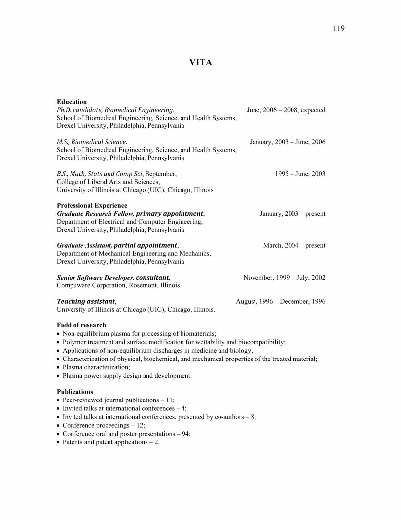
119
VITA
Education Ph.D. candidate, Biomedical Engineering, June, 2006 – 2008, expected School of Biomedical Engineering, Science, and Health Systems, Drexel University, Philadelphia, Pennsylvania M.S., Biomedical Science, January, 2003 – June, 2006 School of Biomedical Engineering, Science, and Health Systems, Drexel University, Philadelphia, Pennsylvania B.S., Math, Stats and Comp Sci, September, 1995 – June, 2003 College of Liberal Arts and Sciences, University of Illinois at Chicago (UIC), Chicago, Illinois Professional Experience Graduate Research Fellow, primary appointment, January, 2003 – present Department of Electrical and Computer Engineering, Drexel University, Philadelphia, Pennsylvania Graduate Assistant, partial appointment, March, 2004 – present Department of Mechanical Engineering and Mechanics, Drexel University, Philadelphia, Pennsylvania Senior Software Developer, consultant, November, 1999 – July, 2002 Compuware Corporation, Rosemont, Illinois. Teaching assistant, August, 1996 – December, 1996 University of Illinois at Chicago (UIC), Chicago, Illinois. Field of research Non-equilibrium plasma for processing of biomaterials; Polymer treatment and surface modification for wettability and biocompatibility; Applications of non-equilibrium discharges in medicine and biology; Characterization of physical, biochemical, and mechanical properties of the treated material; Plasma characterization; Plasma power supply design and development. Publications Peer-reviewed journal publications – 11; Invited talks at international conferences – 4; Invited talks at international conferences, presented by co-authors – 8; Conference proceedings – 12; Conference oral and poster presentations – 94; Patents and patent applications – 2.