14chem.engr.utc.edu/.../x2008-fa/435-moss/distillation-ch14.pdf · 14 distillation- column...
TRANSCRIPT

14 Distillation- Column
Material-Balance Control
14.1 MATHEMATICAL MODEL-OPEN LOOP
i n this chapter we will look at the relationship between level control in the overhead condensate receiver and that in the column base for several different column-control schemes. Since flows are commonly measured in pounds/unit time, we will use these units instead of molar ones. Later, in Chapter 16, we will look at individual level controls in more detail.
To illustrate mathematical modeling for column material-balance control, let us first use the conventional column of Figure 14.1. The feed, tpF, is split by the column into two parts: top product, wD, and bottom product, W E . It is assumed that vent losses overhead are negligible. It is further assumed that the heat-transfer dynamics of both the condenser and the reboiler are negligible; this will be true for most columns. Let us start at the column base and work up. For convenience the equations are written in Laplace transform notation.
Column Base, Including Reboiler
where
(14.1)
w l = liquid flow fiom first tray, Ibm/min wp = vapor flow leaving column base, lbm/min
327

328 Dirtillation-Column Material-Balam Control
FIGURE 14.1 Distillation column material balance

14.1 Mathnnntiurl Moa2l-Open Loop 329
Next:
where
WB = bottom product flow, Ibm/min WB = liquid inventory in column base, Ibm,
within the level transmitter span, (AH,), 5 = Laplace transform variable
pB = density, Ibm/ft3 of liquid in column base
AB = cross-sectional area of column base, fi? H B = liquid level in base, feet
If the reboiler is heated by steam:
(14.2)
(14.3)
where An = latent heat of steam, pcu/lbm
= pcu/lbm, at column base latent heat of process fluid,
ws = steam flow, Ibm/min
Usually vapor flow changes are propagated up the column very rapidly. Therefore, no great error is introduced by assuming that they appear instan- taneously at the column top.
Feed Tray
The feed-tray material balance is usually written in terms of molar flows: V R = F(1 - 4) + (14.4)
where VR = vapor flow leaving feed tray, mol/min F = feed flow, mol/min Vs = vapor flow entering feed tray, mol/& q = enthalpyfactor - (Enthalpy of feed as vapor at dew point - Actual feed enthalpy) -
Molar latent heat of vaporization of feed - (LS - L R ) -
F L R = liquid flow from top tray, mol/min Ls = liquid flow from feed tray, mol/&

Note that if the feed is a liquid at its boiling point, q = 1 and V, = V,.
It is also true that: If the feed is subcooled liquid, q is greater than 1 and V' is less than V,.
V, + F + Lf+, = L f + V, (14.5) From the definition of q above we can write:
Lf+l - Lf = -Fq (14.6) In terms of weight units equation (14.6) becomes:
Note that: wF = feed, Ibmlmin
wf = liquid flow from the feed tray, Ibmlmin
From equation (14.7) :
(14.7)
(14.8)
Since (wf+J++,), (u+/q, and (wdLf) are constants, we can rewrite equation (14.8) in Laplace transform notation:
(14.9)
or
wf(s) = k2wf+1(2) + k3WF(I) + kdq(f) (14.10)
Usually k2 = 1, k3 = q, and k4 = w F , although the last may not be true
In going back to equation (14.4) and expressing it in weight units, we if the feed composition is radically different from feed-tray composition.
obtain:
(14.11)
whence

14.1 Mathematrcal MoakL-Open Loop 331
or Wr-l(s) = ~ w A J ) + k7~14s) - k d s ) (14.13)
Usually b6 = 1, k7 = 1 - q, and k8 = wF, although the last two may not hold if feed composition is radically different from feed-tray composition.
Stripping-Section Liquid-Flow Dynamics
The transfer function between w1 and wfis:
(14.14)
where G&) is the cumulative effect of the individual tray hydraulic lags, each with a hydraulic lag, T~ (no inverse response assumed):
where Ns = number of trays from the column
base to the feed tray
Enriching-Section Liquid-Flow Dynamics
where w m = liquid flow (internal reflux)
from top tray, Ibm/min
where NR = number of trays above the feed tray
a1 = N R T ~
(14.15)
(14.16)
(14.17)
Note that: (14.18)

332
where
Dhill&m-Colirmn Mated-Baluna Control
CP - APT
K, = 1 -k -((To - TR)
wR = external reflux flow, Ibm/min
Overhead Material Balance
The vapor flow to the condenser is:
where
Am = latent heat of vaporization of process
c,, = process fluid specific heat, pcu/lbm"C
To = average vapor temperature, "C
T R = average external reflux temperature, "C
wc = vapor flow to condenser, lbm/min
fluid specific heat, pcu/lb
-
-
Note that if there is no subcooling, wc = wtP1.
Condensate Receiver Material Balance
fp , (S) - wD(S) - wR(S) = w ~ ( ~ ) S
where
wD = top-product flow rate, Ibm/min
WT = condensate receiver inventory, lbm
If the condensate receiver is a vertical, cylindrical vessel:
-- WAS) - HAS) P A T
where HT = height of liquid, feet, in receiver
pT = density of top product, lbm/ft3
AT = cross-sectional area of receiver, ftz
(14.19)
(14.20)
(14.21)

14.2 Control in the Direction of FIap 333
The preceding equations now can be combined into the signal flow dagram of Figure 14.2. As can be seen, the feed flow, external reflux, steam flow, and top- and bottom-product flows are all inputs. By providing the proper additional connections, we can design any desired type of material-balance control.
Limitations of Preceding Analysis
There are three factors that limit the accuracy of the precedmg analysis. The first of these relates to the phenomenon of inverse response discussed in Chapter 13. It is characteristic of valve tray columns and some sieve tray columns operating at low boilup rates. It exercises its most serious effect in those columns where base level is controlled via steam flow. If the level becomes too high, the level controller increases the steam flow. But this causes a momentary increase in base level due to the extra liquid coming down the column (also due to thennosyphon reboiler “swell”). Without proper design the level controller can become very confused. This is discussed in detail in Chapter 16.
The second limiting factor is entrainment. Normally we assume that the only way we get liquid overhead is by condensing vapor. But at high boilup rates, entrainment may be severe enough to invalidate the simple material- balance model we have developed.
The third factor is the simplified, steady-state treatment of the feed tray. For purposes of this chapter, we do not believe this introduces a serious error. Feed tray dynamics will be dealt with more rigorously in Chapter 18.
14.2 CONTROL IN THE DIRECTION OF FLOW
Let us look at a material-balance control scheme that is in the direction of flow. Let feed rate be set by averaging level control of the feed tank, let condensate receiver level set top-product flow, and let column base level set bottom-product flow. We will assume that each level controller is cascaded to the appropriate flow controller.
Overhead Level Control
The necessary additional equation (no subcooling) is: 1
= ~T(.c)KmbrKdrrGdt(S) x - KwD
where psi
lbm/min Ke = distillate flow-meter gain,
(14.22)
Note: linear flow meter - - (WD)-

334 DirtiuatiOn-Column Mated-BalanU Control
FIGURE 14.2 Signal flow diagram for column material balance

14.2 G m ~ l in the Direction of Flow 335
( I V ~ ) ~ ~ = top-product flow-meter span, lbm/min
Kdrr = controller gain, psi/psi
G,(s) = controller dynamic gain
KdT = receiver level transmitter gain, psi/fi Note that we have ignored the dynamics of level measurement and of the flow control loop. For averaging level control, this introduces little error.
We can now prepare the partial signal flow diagram of Figure 14.3. From this we can see by inspection that:
(14.23) W D ( 4 - 1 -
IVd5) - IVR($) 1 + ~chrGchr(.T)Kdf A T P T K ~
= &d%l7-(5) (14.23a)
For pneumatic instruments:
(14.24) 12 psi
(AHT ) T K& =
where ( A H T ) T is the level transmitter span, in feet, for a 3-15-psig output. We can now define a characteristic time constant:
(14.25) PTAT(AHT)T &~(wD ),ax
[THIT =
FIGURE 14.3 Signal flow diagram-condensate receiver
336 DiniUation-Colurnn Matffial-Balanu Cmttvl
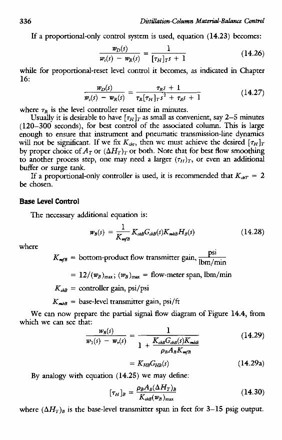
If a proportional-only control system is used, equation (14.23) becomes:
(14.26)
whde for proportional-reset level control it becomes, as indicated in Chapter 16:
(14.27) tpg(s) = TRs + 1 pc(c(s) - fpR(s) rR[TH]Ts2 + rl?.s -k 1
where rR is the level controller reset time in minutes. Usually it is desirable to have [rHIT as small as convenient, say 2-5 minutes
(120-300 seconds), for best control of the associated column. This is large enough to ensure that instrument and pneumatic transmission-line dynamics will not be sigdcant. If we fix K,,, then we must achieve the desired [ 7 H ] T
by proper choice of A T or (AHT)= or both. Note that for best flow smoothing to another process step, one may need a larger (rH)*, or even an additional buffer or surge tank.
If a proportional-only controller is used, it is recommended that KAT = 2 be chosen.
Base Level Control
The necessary additional equation is:
(14.28)
where psi
Ibm/min KnsB = bottom-product flow transmitter gain,
= 12/(~~)~=; ( f p B ) - = flow-meter span, Ibm/min
KdB = controller gain, psi/psi
KmhB = base-level transmitter gain, psi/fi
We can now prepare the partial signal flow diagram of Figure 14.4, fiom
(14.29)
which we can see that: wB(s) - 1 -
fPl(4 - fp&) 1 + KC~BGC~B (s)Km/l~ P d B K n g r B
= KHBGHB(s) By analogy with equation (14.25) we may define:
(14.29a)
(14.30)
where (AHT), is the base-level transmitter span in feet for 3-15 psig output.

14.3 Control in Dire& Opposite to Flow 337
W B ( 4 - 1
For proportional-only control, equation ( 14.29) becomes:
(14.31) - W l ( 4 - tp,(S) [THIBJ + 1
while for proportional-reset control it is:
(14.32) W B ( S ) - TR$ + 1 -
tPl(S) - fpp(S) TR[TH]BS’ + TRS + 1 where T~ is the level controller reset time in minutes.
It is usually desirable for best control of the associated column to make ( T ~ ) ~ = 10-15 minutes, and if KdE is specified, then the proper time constant is achieved by choice of AB or ( AHT)B, or both. For proportional-only control, KchB = 2 is recommended. Note that for best flow smoothing to another process step, one may need a large ( T ~ ) ~ , or even an additional surge or buffer tank.
We can now prepare the overall closed-loop material-balance dagram of Figure 14.5. Note that the two level controls are independent and noninteracting. If we were to add reflux/feed and steam/feed ratio controls, this statement would st i l l be true.
14.3 CONTROL IN DIRECTION OPPOSITE TO FLOW As an example let us choose the case of Figure 6.5 where top-product flow
is the demand flow, condensate receiver level sets steam flow, base level sets feed flow, and both reflux and bottom-product flow are ratioed to top-product flow. As before, level controllers are cascaded to flow controls with linear flow meters.
FIGURE 14.4 Signal flow diagram-column base

338 DtitiUatMn-Column MaterialB&m Control
FIGURE 14.5 Signal flow diagram-material balance control in direction of flow

14.3 Control in Direction Opposite to Flow
Condensate Receiver Level Cascaded to Steam Flow Control
The necessary equation here is:
1 %(5) = - K c h T G & T ( 5 ) W 5 )
K?fj
339
(14.33)
where
K,qj = steam-flow transmitter gain, PSI Ibm/min
12/(w5),, where (w5)- = steam
flow meter span, lbm/min
Nore that we assume the flow control loop to be very fast compared with other dynamics. Also, since we have a cascade system, the steam flow transmitter should have a linear relationship between flow and transmitter output. If an orifice flow meter is used, the AP transmitter should be followed by a square root extractor.
Base Level Adjusts Feed Flow
(14.34)
where psi
lbm/min = feed flow-meter gain,
= 12/(%)max
( B J ~ ) ~ ~ = feed flow-meter span, lbm/min
Reflux Flow Ratioed to Distillate Flow
Let: Q(5) = ~RDGRD(-T)fPD(5) (14.35)
Physical techniques for accomplishing this are discussed in reference 2.
Bottom-Product Flow Ratioed to Distillate Flow
(14.36)
Closed-Loop Signal-Flow Diagram
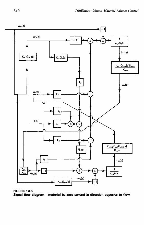
The closed-loop signal-flow diagram of Figure 14.6 may now be prepared. To show the relationship between wD and wF more clearly, it is redrawn into the form of Figure 14.7. This is a much more complex diagram than that of
340 Disdla&a-Column M a t d - B a l a w Control
FIGURE 14.6 Signal flow diagram-material balance control in direction opposite to flow

14.3 C
ontrol in Direction Opposite to F
h
341
9 - g r
L
8
Lr, - 0 C
0 a
e g 2% g
s
gs -m
- 3
k

Figure 14.5. The functions Gm(s) and GBD(s) will have to be chosen with care because of potential difficulties with stability. Also, these two functions must be chosen with primary regard for material-balance control, not composition control. This point of view is at variance with that sometimes expressed elsewhere in the literature. Finally, it is probably apparent that conventional “tuninjf‘ procedures are essentially useless for a system of this complexity; control functions must be correctly preselected, and control-loop parameters calculated ahead of plant operation.
14.4 MATERIAL-BALANCE CONTROL IN SIDESTREAM DRAWOFF COLUMNS
Let us consider two cases: (1) vapor sidestream, and (2) liquid sidestream. Feed is assumed to enter at its boiling point.
Vapor Sidestream
As an example let us consider a column such as that illustrated in Figure 7.1 .. This column has a small top-product purge, a small bottom-product purge, and a side product that is most of the feed. Base level adjusts side draw and reflux drum level sets reflux flow. Three flows are ratioed to feed: top product, bottom product, and steam.
About the only new relationship we need is that which defines vapor flow up the column above the point of side draw:
K u b B
K+ (14.37) tp, (s) = - K h B G c h B ( w . B ( J )
= sidestream flow, Ibm/min where
psi Ibm/min
K+ = sidestream flow-meter gain,
12 -- - (tp,)max
and
fP&) = f P v ( 4 - fP,w
The steam flow is set by ratio to the feed flow: (14.38)
(14.39)
(14.40)
and

14.5 Top and Bottom Level Control Com&u&ms 343
The two remaining ratio controls are defined as follows:
(14.41) 1 WB(S) = K#$FKR3GR3(5)-
K?@ and
(14.42)
The pertinent equations may now be assembled into the form of Figure 14.8.
1 %(S) - K$F&&&)- W F ( 4 rc,,
Liquid Sidestream
above the feed tray. Then we define: In this case we will assume that the liquid side draw is taken from a point
(14.43)
(14.45)
With the same control scheme in mind, we can prepare the signal flow diagram of Figure 14.9.
14.5 TOP AND BOTM)M LEVEL CONTROL COMBINATIONS Considerable controversy has existed on the question of whether to have
the condensate receiver level adjust the reflux flow or the top-product flow. One well-known author argues strongly for the former. Controversy also exists as to whether it is better to have column-base level control bottom-product flow or the reboiler heating medium, usually steam. Another expert recommends the second. It is probably apparent that we cannot follow both recommendations; at least one of the two levels must control a drawoff flow.
There are many columns operating today with condensate receiver level controlling reflux and base level controlling bottom-product flow. There are other columns in which condensate receiver level adjusts top-product flow while base level manipulates steam flow. How do we choose between them, assuming that we cannot, for some reason, have both levels adjust drawoff flows?
It seems to us that it is largely a matter of convenience. In a superfiactionator, for example, the reflux flow may be ten or more times greater than the top- product flow. Inventory in the receiver may be regulated a little more readily by manipulation of the large flow than of the small one. This does not mean that level control via the small flow is either impossible or impractical. It does
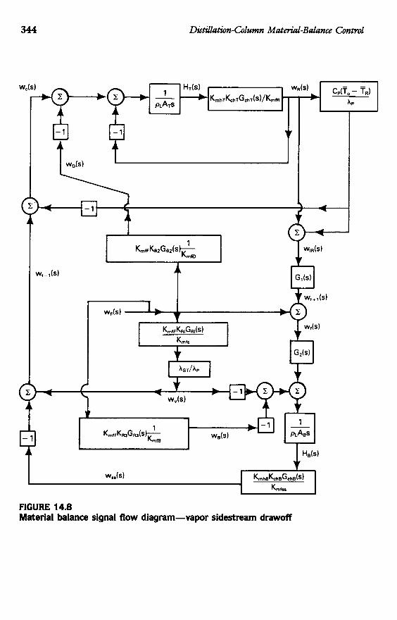
344 Dutdhthn-Column Ma&riul-Balana Control
FIGURE 14.8 Material balance signal flow diagram-vapor sidestream drawoff
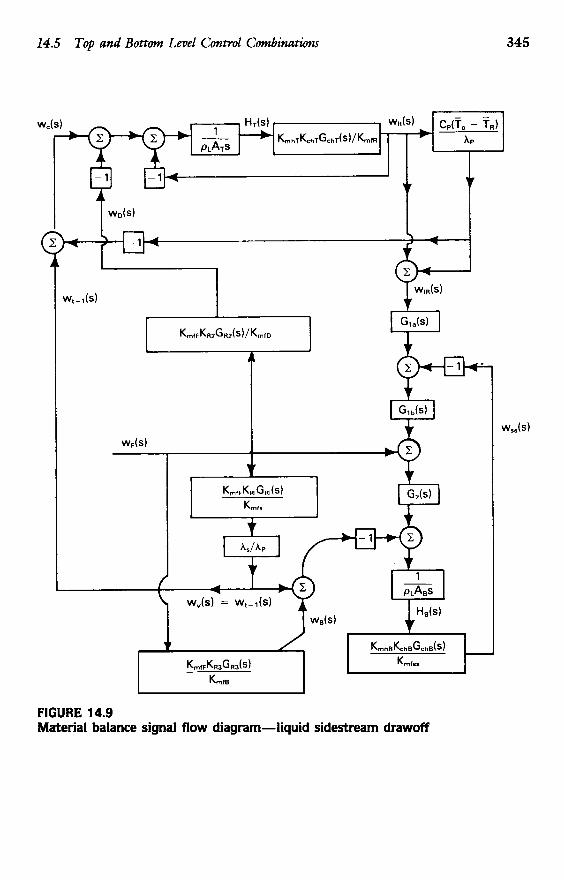
14.5 Top and Bottom Level Control Combinatwns 345
FIGURE 14.9 Material balance signal flow diagram-liquid sidestream drawoff
346 Dktdhtim-Column Materiul-Balance Control
mean that high- and low-level protection by means of overrides on reflux flow would be needed. Thls is discussed in Chapters 9 and 16.
It is sometimes argued that where reflux flow is much greater than top- product flow, one may control top composition more easily by adjusting top- product flow than by adjusting reflux flow. Actually a little algebra will show that there is not much difference, and that the difference is against the argument rather than in favor of it. If, for example, a change in feed rate or feed composition changes overhead composition, there will be a certain change in reflux flow and another change in top-product flow required to restore the top composition. These two required changes are the same in the steady state regardless of which variable is manipulated to control top composition. Composition control via distillate (top product) has the disadvantage that no change in composition takes place until the reflux flow changes. Since reflux is controlled by level, the dynamics of the level control loop appear in the composition control loop. This means, generally, that we cannot use averaging level control; we must design for tight level control. For this reason we normally prefer to control composition via reflux.
A similar line of reasoning may be followed at the base of the column, and leads to the conclusion that we would normally prefer to control base composition by manipulating boilup. Controhg base level by steam has another disadvantage if a thermosyphon reboiler is used; interchange of inventory between column base and reboiler sometimes leads to severe dynamic problems. This is discussed in Chapters 4, 15, and 16.