distributed plastic gapped magnetic shielding to electromagnetic … · 2016-12-19 · distributed...
TRANSCRIPT

Distributed Plastic Gapped Magnetic Shielding to
Electromagnetic Interference for Electric
Transportation
Cheng Ka-wai Eric and Zou Yu Department of Electrical Engineering, The Hong Kong Polytechnic University, Hong Kong
Email: {eeecheng, y.zou}@polyu.edu.hk
Abstract—Magnetic shielding is an important design for all
electrical system. This is especially important to today’s
electric mobility because nearly all traction drives are using
electric motor and they are driven by high frequency carrier
wave from 1kHz to 100kHz. The interference to the signal
system of vehicle control unit should cost a damaging effect.
Besides the use of filter of metal shielding, a new plastic
based magnetic shielding technique is introduced that
provides a flexible shielding for the EMI isolation. The new
material is especially useful for transportation system
because they are light weight, non-brittle, lower cost and
prominent performance in high frequency.
Index Terms—EMI Shielding, Plastic magnetic, high
frequency, EMC, EMI, railway system, electric mobility
I. INTRODUCTION
Electromagnetic interference is now the key safety
issue in transportation. High frequency power operation
in traction system is now very common. For high-speed
rail, the power level is in 10 MW and voltage is in 27.5
kV. The motor is electric and the switching frequency or
the carrier frequency is 5kHz. The switching action of the
transistors in the motor inverter generates high frequency
radiation. The radiation will have penetration to the
control electronics, signal system, vehicle computer.
Therefore a good shielding is needed for the enclosure
and also for the cable that is used to conduct the signals.
The power cable is also needed to have some shielding
method to reduce the emission due to the high frequency
and high power field [1], [2].
Conventional, electromagnetic interference (EMI)
shielding is using braided/foil-type or solid metal but they
are bulky and also they are conductor [3], [4]. It will
impose electric safety issue because of the metal shielded
may cause electrocution. The operational voltage for
vehicle is high. For high speed rail, the overhead line is
25-27.5kVAC. It is conducted by a pantograph to the
train car and then reduced to 1kV by the transformer
rectifier unit. The DC is then inverted to drive the motor.
Each step has high voltage from tens of kV to 1kV. It
needs to provide control waveforms to the motor that is
using high frequency as a carrier. This is called carrier
Manuscript received July 11, 2016; revised December 11, 2016.
wave. The frequency is from 1kHz to 100kHz. Therefore
the high frequency and high voltage are imposed in the
train system. For electric vehicle, the voltage is derived
from the battery. The voltage is from 200V to 650V. It is
then inverted to motor for traction drive. The frequency is
usually high at 10kHz to 100kHz. Therefore the shielding
is also critical. For high frequency of tens of kHz, the
emission due to high frequency is extreme and the EMI
emission is also high [5], [6]. The screening using
conventional metal based is conventional. The screening
using fabric magnetic has been reported in ref [5]-[7]. It
is interesting to use lower relative permeability thin
material, but how is the screening performance? For high
voltage condition and the carrier wave is also at high
frequency, the dv/dt is also high and therefore the
emission due to the high frequency switching is therefore
high.
This paper has presented a plastic bonded magnetic
shielding, analyzing the basic features including the flux
line carrying capability against relative permeability and
calculating the surrounding magnetic field of the
shielding. The values of flux densities around the
shielding with varied conditions, involving high
frequency (AC) and Direct Current (DC) excited fields. It
suggests that the shielding is a promising candidate to
isolate interfere magnetic fields. It can serve the high rail
system for EMI in future. Two typical applications using
this material are given in the end and, the simulation
results also validate that this material is capable of
preventing interfered magnetic fields.
II. THE PLASTIC BONDED MAGNETIC SHIELDING
A. Classical EMI Shielding
Under the intensive EMI a common method for
screening is to use metal and ferrites. The general
comment is that the metal solid shield is extensive, heavy
and not flexible. It makes the overall weight higher.
Therefore it is not suitable to be used for transportation
system. Also the solid metal does not have good
frequency response. Under high frequency, the
permeability of the materials drops significantly. Ferrite
is a very good material. It has been used in EMI test
chamber for EMI isolation. However, it is also expensive,
brittle and heavy as well. The transportation, the cart or
International Journal of Mechanical Engineering and Robotics Research Vol. 6, No. 1, January 2017
© 2017 Int. J. Mech. Eng. Rob. Res. 11doi: 10.18178/ijmerr.6.1.11-15
vehicle may be experienced with vibration, which will
make the ferrite shielding easily to get broken. Therefore
both of them may not be suitable for transportation
systems.
Also when screening is needed to be done on cable, the
above two materials are not suitable because flexible
shape is needed for cable shield. In the past, the braided
type of cable shielding is used, but it is still made from
solid metal and the frequency range is not very wide.
B. The New Shielding Materials
Low frequency screening is simple and is a well-
known technology. Frequency response, especially at
high frequency is poor. Usually or high frequency
operation, the screening materials should be formed by
small ferromagnetic materials in the size of micrometer.
Ferrite is supposed to fulfil this requirement, but its
adverse feature makes it difficult to be used in
transportation system. Also the thickness is another
concern. Usually a screening needs only thin wall for
magnetic isolation, and a few mm is good enough. When
ferrite is used, it is difficult to use ferrite thickness of a
few mm because the material is brittle. Ferrite usually has
relative permeability of over 2000. That is the magnetic
flux conductivity in ferrite is 2000 times of air. In
practice, a lower value may be good enough.
A new plastic based material has been developed that
has both feature of plastic and ferromagnetic. A plastic
based material is preferred to be the screening because it
is more flexible and not easy to be brittle. It can also been
made with thickness of a few mm sheet that is more
practical for enclosure, screening and even cable shield.
The new plastic based material has been developed that
can be programmed to have µr =50, 100 and 200 [8]. It is
a plastic mixed with magnetic materials. Fig. 1 shows the
extrusive composites formed by the mix of the plastic and
the magnetic powder.
The magnetic is using Ni, Co and Mn. Different
combination of the mix with plastic can create different
permeability materials. The size of the ferromagnetic
particles is in powder form, in the size of tens to a few
µm. Because the use of the metal powder is lower than
solid metal, the cost is lower. The concept is similar to
distributed airgap to control the effective permeability. It
is anticipated that to use the materials to develop the
shielding of the high power field. It is to be tested them
under different conditions of thickness of the materials as
an enclosure. One is a shield and the other is an enclosure
and a cable.
Figure 1. The extrusive composites of the proposed material
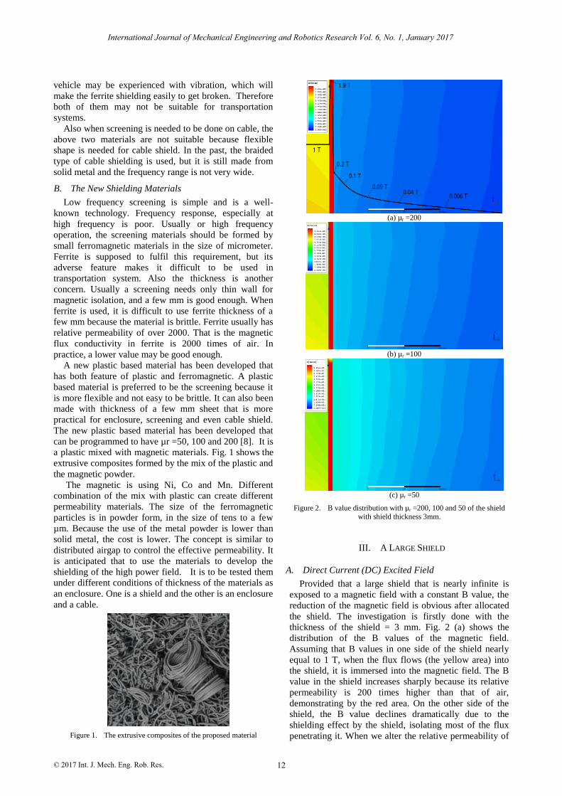
(a) µr =200
(b) µr =100
(c) µr =50
Figure 2. B value distribution with µr =200, 100 and 50 of the shield with shield thickness 3mm.
III. A LARGE SHIELD
A. Direct Current (DC) Excited Field
Provided that a large shield that is nearly infinite is
exposed to a magnetic field with a constant B value, the
reduction of the magnetic field is obvious after allocated
the shield. The investigation is firstly done with the
thickness of the shield = 3 mm. Fig. 2 (a) shows the
distribution of the B values of the magnetic field.
Assuming that B values in one side of the shield nearly
equal to 1 T, when the flux flows (the yellow area) into
the shield, it is immersed into the magnetic field. The B
value in the shield increases sharply because its relative
permeability is 200 times higher than that of air,
demonstrating by the red area. On the other side of the
shield, the B value declines dramatically due to the
shielding effect by the shield, isolating most of the flux
penetrating it. When we alter the relative permeability of
International Journal of Mechanical Engineering and Robotics Research Vol. 6, No. 1, January 2017
© 2017 Int. J. Mech. Eng. Rob. Res. 12

the shield from µr =200 to 100 and 50, as shown in Fig. 2
(b) and Fig. 1 (c), the reduction speed of the B value
shielded for the opposite side decreases. It suggests that
the higher the relative permeability the shield possesses,
the faster of the reduction of the B value is. More
importantly, the B value before passing through the shield
decreases slightly with the decrease in relative
permeability of the shield, which shows that the flux lines
can pass through shields with lower relative permeability
easier, similar to that water can overflow a low dam.
(a) µr =200
(b) µr =100
(c) µr=50
Figure 3. The magnetic flux density distribution in the constant B value 0.5 T by using different shields with relative permeability, (a) 200,
(b) 100 and (c) 50, respectively.
Likewise, after the constant left B value is adjusted to
0.5 T, the distribution of flux density of the whole area is
shown in Fig. 3 with the same conditions as Fig. 2.
Compared with that of Fig. 2, the values of the overall
flux density declines as the constant B value in the left
side of the shield is halved. It can be seen that the
magnetic flux density of Fig. 3 (a) drops significantly to
around zero (blue zone in the right), totally shielded the
magnetic field. From Fig. 3 below, it can be seen that the
magnetic flux density distributions. The green area
denotes the B value is 0.5 T and the red area is much
larger than this value where the shield is allocated,
followed by an air environment with much lower flux
densities in the right part.
B. Alternative Current Excited Magnetic Field
The characteristic of the shield is also analyzed by
means of three-dimensional (3D) finite element method
(FEM). Under a frequency at 10 kHz, flux-carried shields
with different relative permeability from 200, 100 to 50
are shown in Fig. 4. It is obvious from Fig. 4 (a) and Fig.
4 (b) that the shield with higher relative permeability can
hold more flux lines, suggesting it can prevent more flux
lines outside the shield. After the relative permeability is
adjusted to 50, the flux line distribution from Fig. 4 (c)
varies a little, compared with Fig. 4 (b). This
phenomenon suggests that when the relative permeability
of the shield is small, the AC magnetic field imposes a
slight impact on the shield, with a small relative
permeability varied. In all cases, the screened filed is very
small. This can be seen from the colour blue of the
environment.
(a)µr =200 (b) µr =100 (c) µr =50
Figure 4. The flux distribution with the shield in different relative permeability imersed in a high frequency magnetic field.
(a) f=10 kHz (b) f=100 kHz
Figure 5. The flux distribution of shield under high frequency environment.
However, the frequency of the magnetic field takes a
significant influence to the shield as shown in Fig. 5. Fig.
5 (a) shows the flux distribution of around the shield
International Journal of Mechanical Engineering and Robotics Research Vol. 6, No. 1, January 2017
© 2017 Int. J. Mech. Eng. Rob. Res. 13
under 10 kHz of the magnetic field and Fig. 5 (b) gives
that under 100 kHz of the magnetic field. The difference
between the two conditions is obvious. The flux density
around the shield experiences a dramic increase in the
rise of the frequency. It can also illustrate that the shield
is capable of carrying the flux lines even in a high
frequency environment.
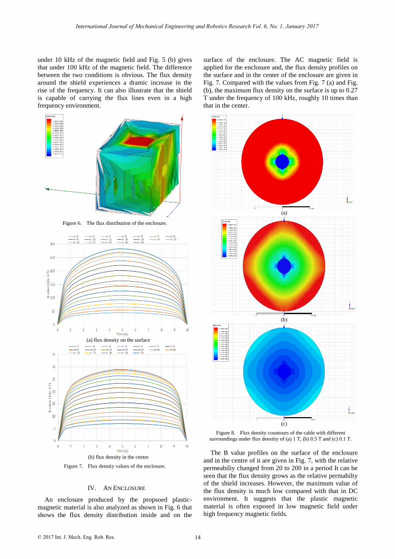
Figure 6. The flux distribution of the enclosure.
(a) flux density on the surface
(b) flux density in the centre
Figure 7. Flux density values of the enclosure.
IV. AN ENCLOSURE
An enclosure produced by the propsoed plastic-
magnetic material is also analyzed as shown in Fig. 6 that
shows the flux density distribution inside and on the
surface of the enclosure. The AC magnetic field is
applied for the enclosure and, the flux density profiles on
the surface and in the center of the enclosure are given in
Fig. 7. Compared with the values from Fig. 7 (a) and Fig.
(b), the maximum flux density on the surface is up to 0.27
T under the frequency of 100 kHz, roughly 10 times than
that in the center.
(a)
(b)
(c)
Figure 8. Flux density countours of the cable with different surroundings under flux densitiy of (a) 1 T, (b) 0.5 T and (c) 0.1 T.
The B value profiles on the surface of the enclosure
and in the centre of it are given in Fig. 7, with the relative
permeabiliy changed from 20 to 200 in a period It can be
seen that the flux density grows as the relative permabilty
of the shield increases. However, the maximum value of
the flux density is much low compared with that in DC
environment. It suggests that the plastic magnetic
material is often exposed in low magnetic field under
high frequency magnetic fields.
International Journal of Mechanical Engineering and Robotics Research Vol. 6, No. 1, January 2017
© 2017 Int. J. Mech. Eng. Rob. Res. 14
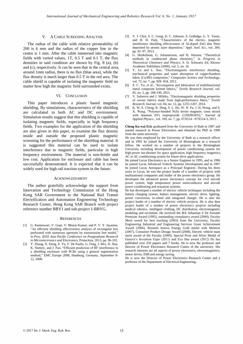
V. A CABLE SCREENING ANALYSIS
The radius of the cable with relative permeability of
200 is 6 mm and the radius of the copper line in the
centre is 1 mm. After the cable immersed into magnetic
fields with varied values, 1T, 0.5 T and 0.1 T, the flux
densities in said condition are shown by Fig. 8 (a), (b)
and (c), respectively. It can be seen that in the central area,
around 1mm radius, there is no flux (blue area), while the
flux density is much larger than 0.5 T in the red area. The
cable shield is capable of isolating the magnetic field no
matter how high the magnetic field surrounded exists.
VI. CONCLUSION
This paper introduces a plastic based magnetic
shielding. By simulations, characteristics of the shielding
are calculated in both AC and DC environment.
Simulation results suggest that this shielding is capable of
isolating magnetic fields, especially in high frequency
fields. Two examples for the application of the shielding
are also given in this paper, to examine the flux density
inside and outside the proposed plastic magnetic
screening for the performance of the shielding material. It
is suggested this material can be used to isolate
interference due to magnetic fields, particular in high
frequency environment. The material is non-brittle and
low cost. Application for enclosure and cable has been
successfully demonstrated. It is expected that it can be
widely used for high rail traction system in the future.
ACKNOWLEDGMENT
The author gratefully acknowledge the support from
Innovation and Technology Commission of the Hong
Kong SAR Government to the National Rail Transit
Electrification and Automation Engineering Technology
Research Center, Hong Kong SAR Branch with project
reference number BBY1 and sub-project 1-BBYG.
REFERENCES
[1] G. Kameswari, V. Gopi, V. Bharat Kumar, and P. V. Y. Jayasree,
“An efficient shielding effectiveness analysis of rectangular box perforated with numerous apertures by transmission line model,”
in Proc. IEEE Asia Pacific Conference on Postgraduate Research in Microelectronics and Electronics, PrimeAsia, 2013, pp. 96-102.
[2] Y. Zhang, X. Dong, Z. Yu, F. De Paulis, G. Feng, J. Mix, D. Hua,
K. Slattery, and J. Fan, “Efficient prediction of RF interference in a shielding enclosure with PCBs using a general segmentation
method,” EMC Europe 2008, Hamburg, Germany, September 8-12, 2008.
[3] Y. J. Choi, S. C. Gong, D. C. Johnson, S. Golledge, G. Y. Yeom, and H. H. Park, “Characteristics of the electro- magnetic
interference shielding effectiveness of Al-doped ZnO thin films
deposited by atomic layer deposition,” Appl. Surf. Sci., vol. 269, pp. 92–97, 2013.
[4] G. Henkelman, G. Johannesson, and H. Jónsson, “Theoretical methods in condencsed phase chemistry,” in Progress in
Theoretical Chemistry and Physics, S. D. Schwartz Ed, Kluwer
Academic Publishers (2000), vol. 5, no. 10. [5] Y. Lu and L. Xue, “Electromagnetic interference shielding,
mechanical properties and water absorption of copper/bamboo fabric (Cu/BF) composites,” Composites Science and Technology,
vol. 72, no. 7, pp. 828- 834, 2012.
[6] Z. C. Yu, et al., “Investigation and fabrication of multifunctional metal composite knitted fabrics,” Textile Research Journal, vol.
85, no. 2, pp. 188-199, 2015. [7] V. Safarova and J. Militky, “Electromagnetic shielding properties
of woven fabrics made from high-performance fibers,” Textile
Research Journal, vol. 84, no. 12, pp. 1255-1267, 2014. [8] K. W. E. Cheng, K. Ding, S. L. Ho, W. N. Fu, J. H. Wang, and S.
X. Wang, “Polymer-bonded NiZn ferrite magnetic cores mixed with titanium (IV) isopropoxide (12H28O4Ti),” Journal of
Applied Physics , vol. 109, no. 7, pp. 07A514 - 07A514-3, 2011.
Cheng Ka-wai Eric graduated from the University of Bath in 1987 and
started research in Power Electronics and obtained his PhD in 1990 from the same university.
He was then employed by the University of Bath as a research officer
and in 1991 he joined the University of Birmingham as a research fellow. He worked on a number of projects in the Birmingham
University including development of power conditioning system for high power ion-thruster for space application, high frequency magnetics,
AC to AC conditioning system for future drive applications.
He joined Lucas Electronics as a Senior Engineer in 1995, and in 1996 he joined Lucas Advanced Vehicle Systems Development and in 1997
he joined Lucas Aerospace as a Principal Engineer. During his three years in Lucas, he was the project leader of a number of projects with
multinational companies and leader of the power electronics group. He
developed the advanced power electronics concept for civil aircraft power system, high temperature power semiconductor and aircraft
power conditioning and actuation systems. He has developed a number of electric vehicle techniques including the
battery charging system, battery management, electric drive, lighting,
power conversion, in-wheel and integrated charger. He is also the project leader of a number of electric vehicle projects. He is also then
project leader of a number of power electronics projects including medical robotics, intelligent clothing, DC distribution, electromagnetic
modeling and excitation. He received the IEE Sebastian Z De Ferranti
Premium Award (1995), outstanding consultancy award (2000), Faculty Merit award for best teaching (2003) from the University, Faculty
Engineering Industrial and Engineering Services Grant Achievement Award (2006), Brussels Innova Energy Gold medal with Mention
(2007), Consumer Product Design Award (2008), Electric vehicle team
merit award of the Faculty (2009). Special Prize and Silver Medal of Geneva’s Invention Expo (2011) and Eco Star award (2012) He has
published over 250 papers and 7 books. He is now the professor and director of Power Electronics Research Centre of the university. His
research interests are all aspects of power electronics, electromagnetics,
motor drives, EMI and energy saving. He is now the Director of Power Electronics Research Center and a
professor of the Department of Electrical Engineering..
International Journal of Mechanical Engineering and Robotics Research Vol. 6, No. 1, January 2017
© 2017 Int. J. Mech. Eng. Rob. Res. 15