division 7 - thermal and moisture … 04-16-15 final approved...division 7 - thermal and moisture...
TRANSCRIPT
DIVISION 7 - THERMAL AND MOISTURE PROTECTION Page 1 of 28
CENTRAL PRESBYTERIAN CHURCH OF NEW YORK DIVISION 7-THERMAL AND MOISTURE PROTECTION
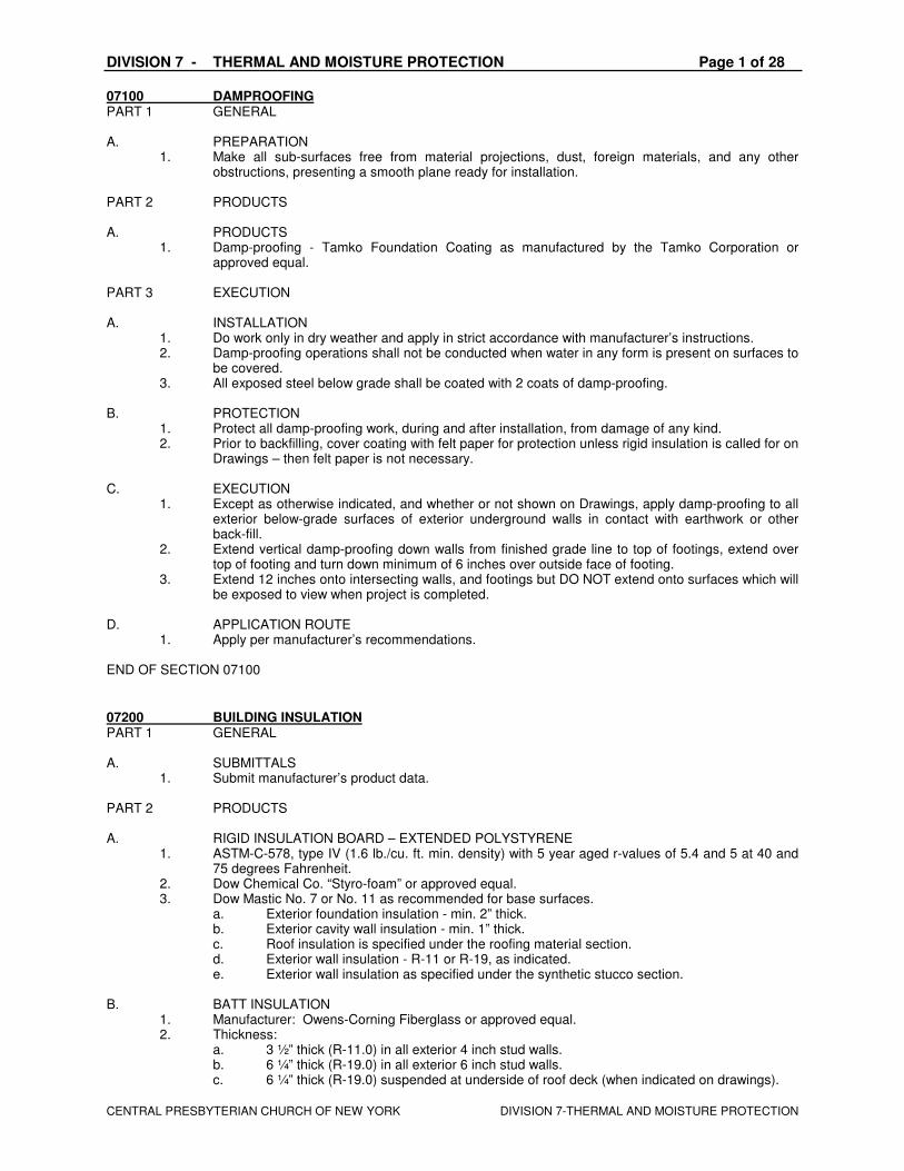
07100 DAMPROOFING PART 1 GENERAL A. PREPARATION
1. Make all sub-surfaces free from material projections, dust, foreign materials, and any other obstructions, presenting a smooth plane ready for installation.
PART 2 PRODUCTS A. PRODUCTS
1. Damp-proofing - Tamko Foundation Coating as manufactured by the Tamko Corporation or approved equal.
PART 3 EXECUTION A. INSTALLATION
1. Do work only in dry weather and apply in strict accordance with manufacturer’s instructions. 2. Damp-proofing operations shall not be conducted when water in any form is present on surfaces to
be covered. 3. All exposed steel below grade shall be coated with 2 coats of damp-proofing.
B. PROTECTION
1. Protect all damp-proofing work, during and after installation, from damage of any kind. 2. Prior to backfilling, cover coating with felt paper for protection unless rigid insulation is called for on
Drawings – then felt paper is not necessary. C. EXECUTION
1. Except as otherwise indicated, and whether or not shown on Drawings, apply damp-proofing to all exterior below-grade surfaces of exterior underground walls in contact with earthwork or other back-fill.
2. Extend vertical damp-proofing down walls from finished grade line to top of footings, extend over top of footing and turn down minimum of 6 inches over outside face of footing.
3. Extend 12 inches onto intersecting walls, and footings but DO NOT extend onto surfaces which will be exposed to view when project is completed.
D. APPLICATION ROUTE
1. Apply per manufacturer’s recommendations. END OF SECTION 07100
07200 BUILDING INSULATION PART 1 GENERAL A. SUBMITTALS
1. Submit manufacturer’s product data. PART 2 PRODUCTS A. RIGID INSULATION BOARD – EXTENDED POLYSTYRENE
1. ASTM-C-578, type IV (1.6 lb./cu. ft. min. density) with 5 year aged r-values of 5.4 and 5 at 40 and 75 degrees Fahrenheit.
2. Dow Chemical Co. “Styro-foam” or approved equal. 3. Dow Mastic No. 7 or No. 11 as recommended for base surfaces.
a. Exterior foundation insulation - min. 2” thick. b. Exterior cavity wall insulation - min. 1” thick. c. Roof insulation is specified under the roofing material section. d. Exterior wall insulation - R-11 or R-19, as indicated. e. Exterior wall insulation as specified under the synthetic stucco section.
B. BATT INSULATION
1. Manufacturer: Owens-Corning Fiberglass or approved equal. 2. Thickness:
a. 3 ½” thick (R-11.0) in all exterior 4 inch stud walls. b. 6 ¼” thick (R-19.0) in all exterior 6 inch stud walls. c. 6 ¼” thick (R-19.0) suspended at underside of roof deck (when indicated on drawings).
DIVISION 7 - THERMAL AND MOISTURE PROTECTION Page 2 of 28
CENTRAL PRESBYTERIAN CHURCH OF NEW YORK DIVISION 7-THERMAL AND MOISTURE PROTECTION
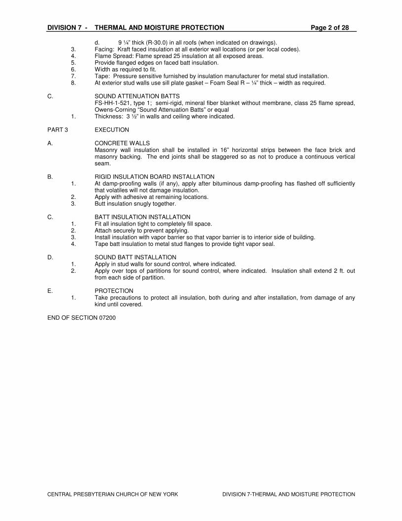
d. 9 ¼” thick (R-30.0) in all roofs (when indicated on drawings). 3. Facing: Kraft faced insulation at all exterior wall locations (or per local codes). 4. Flame Spread: Flame spread 25 insulation at all exposed areas. 5. Provide flanged edges on faced batt insulation. 6. Width as required to fit. 7. Tape: Pressure sensitive furnished by insulation manufacturer for metal stud installation. 8. At exterior stud walls use sill plate gasket – Foam Seal R – ¼” thick – width as required.
C. SOUND ATTENUATION BATTS FS-HH-1-521, type 1; semi-rigid, mineral fiber blanket without membrane, class 25 flame spread,
Owens-Corning “Sound Attenuation Batts” or equal 1. Thickness: 3 ½” in walls and ceiling where indicated.
PART 3 EXECUTION A. CONCRETE WALLS Masonry wall insulation shall be installed in 16” horizontal strips between the face brick and
masonry backing. The end joints shall be staggered so as not to produce a continuous vertical seam.
B. RIGID INSULATION BOARD INSTALLATION
1. At damp-proofing walls (if any), apply after bituminous damp-proofing has flashed off sufficiently that volatiles will not damage insulation.
2. Apply with adhesive at remaining locations. 3. Butt insulation snugly together.
C. BATT INSULATION INSTALLATION
1. Fit all insulation tight to completely fill space. 2. Attach securely to prevent applying. 3. Install insulation with vapor barrier so that vapor barrier is to interior side of building. 4. Tape batt insulation to metal stud flanges to provide tight vapor seal.
D. SOUND BATT INSTALLATION
1. Apply in stud walls for sound control, where indicated. 2. Apply over tops of partitions for sound control, where indicated. Insulation shall extend 2 ft. out
from each side of partition. E. PROTECTION
1. Take precautions to protect all insulation, both during and after installation, from damage of any kind until covered.
END OF SECTION 07200

DIVISION 7 - THERMAL AND MOISTURE PROTECTION Page 3 of 28
CENTRAL PRESBYTERIAN CHURCH OF NEW YORK DIVISION 7-THERMAL AND MOISTURE PROTECTION
07271 SELF-ADHERED AIR AND VAPOR BARRIER MEMBRANES
Self-Adhering Sheet Air Barriers
EXOAIR 110 & 110LT SELF-ADHERED AIR AND VAPOR BARRIER MEMBRANES PART 1 GENERAL 1.01 RELATED DOCUMENTS Drawings and general provisions of the Contract, including General and Supplementary Conditions and Division 1 Specification Sections, apply to this Section. 1.02 SUMMARY
A. The work of this section includes, but is not limited to, the following: materials and installation methods for self-adhered air and vapor barrier membrane system located in the non-accessible part of the wall. Materials and installation methods to bridge and seal the following air leakage pathways and gaps: connections of the walls to the roof air barrier, connections of the walls to the foundations, seismic and expansion joints, openings and penetrations of window frames, store front, and curtain wall, barrier precast and other envelope systems, door frames, piping, conduit, duct and similar penetrations, masonry ties, screws, bolts and similar penetrations. All other air leakage pathways in the building envelope.
B. Related Sections: Other specification sections that directly relate to the works of this section include, but are not limited to, the following: Section 03300 – Cast-In-Place Concrete Section 04200 – Masonry Section 07100 – Dampproofing Section 07200 – Insulation Section 07530 – Roof Membrane Section 07600 – Flashing and Sheet Metal Section 07900 – Joint Sealers Section 08810 – Glazing Section 08410 – Aluminum Entrances and Storefronts Section 09250 – Gypsum Sheathing 1.03 PERFORMANCE REQUIREMENTS Provide an air and vapor barrier constructed to perform as a continuous air and vapor barrier, and as liquid water drainage plane flashed to discharge any incidental condensation or water penetration. 1304.3.1 Air Barriers: The building envelope shall be designed and constructed with a continuous air barrier to control air leakage into, or out of the conditioned space. An air barrier shall also be provided for interior partitions between conditioned space and space designed to maintain temperature or humidity levels which differ from those in the conditioned space by more than 50% of the difference between the conditioned space and design ambient conditions. The air barrier shall have the following characteristics:
1. It must be continuous, with all joints made airtight. 2. It shall have an air permeability not to exceed 0.004 cfm/ft2 under a pressure differential of 0.3 in.
water. (1.57 psf.) (equal to 0.02 L/s/m2 @ 75 Pa.) when tested in accordance with ASTM E2178-01.
DIVISION 7 - THERMAL AND MOISTURE PROTECTION Page 4 of 28
CENTRAL PRESBYTERIAN CHURCH OF NEW YORK DIVISION 7-THERMAL AND MOISTURE PROTECTION
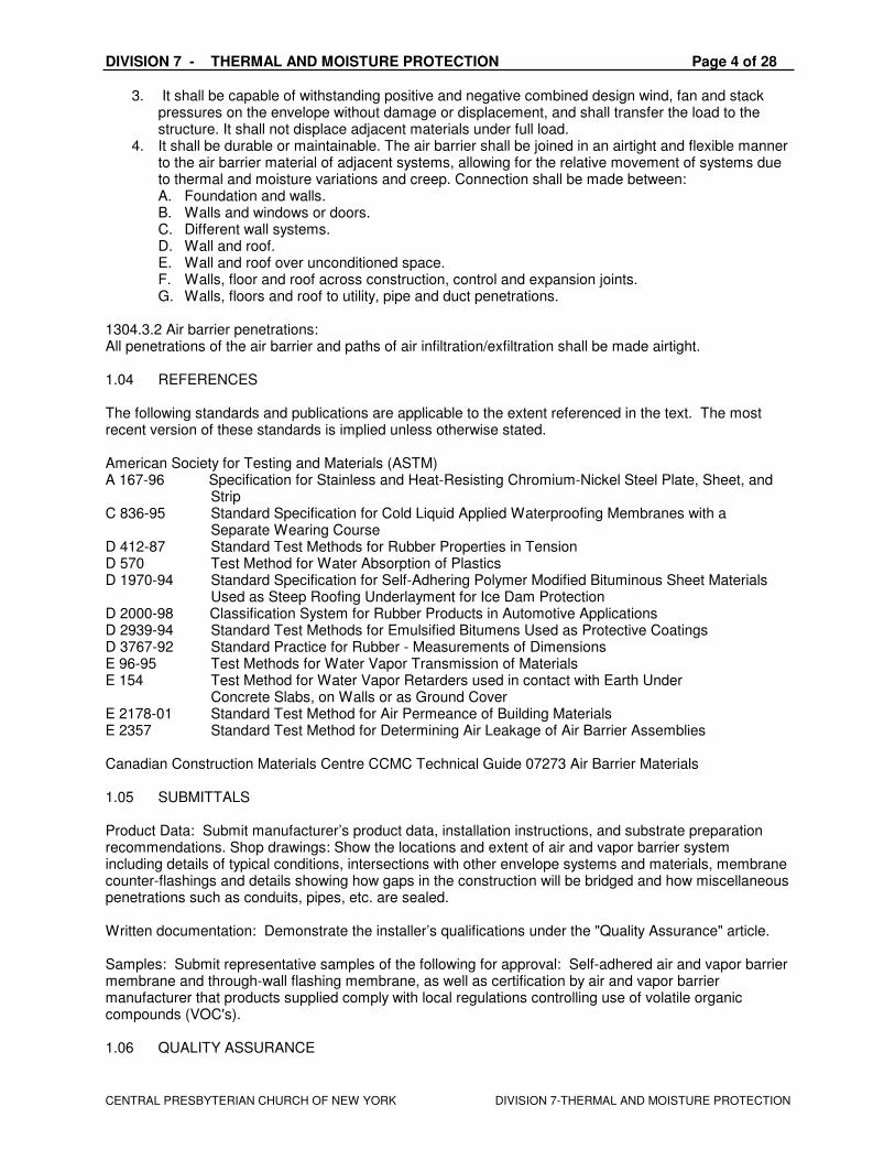
3. It shall be capable of withstanding positive and negative combined design wind, fan and stack pressures on the envelope without damage or displacement, and shall transfer the load to the structure. It shall not displace adjacent materials under full load.
4. It shall be durable or maintainable. The air barrier shall be joined in an airtight and flexible manner to the air barrier material of adjacent systems, allowing for the relative movement of systems due to thermal and moisture variations and creep. Connection shall be made between: A. Foundation and walls. B. Walls and windows or doors. C. Different wall systems. D. Wall and roof. E. Wall and roof over unconditioned space. F. Walls, floor and roof across construction, control and expansion joints. G. Walls, floors and roof to utility, pipe and duct penetrations.
1304.3.2 Air barrier penetrations: All penetrations of the air barrier and paths of air infiltration/exfiltration shall be made airtight. 1.04 REFERENCES The following standards and publications are applicable to the extent referenced in the text. The most recent version of these standards is implied unless otherwise stated. American Society for Testing and Materials (ASTM) A 167-96 Specification for Stainless and Heat-Resisting Chromium-Nickel Steel Plate, Sheet, and Strip C 836-95 Standard Specification for Cold Liquid Applied Waterproofing Membranes with a Separate Wearing Course D 412-87 Standard Test Methods for Rubber Properties in Tension D 570 Test Method for Water Absorption of Plastics D 1970-94 Standard Specification for Self-Adhering Polymer Modified Bituminous Sheet Materials Used as Steep Roofing Underlayment for Ice Dam Protection D 2000-98 Classification System for Rubber Products in Automotive Applications D 2939-94 Standard Test Methods for Emulsified Bitumens Used as Protective Coatings D 3767-92 Standard Practice for Rubber - Measurements of Dimensions E 96-95 Test Methods for Water Vapor Transmission of Materials E 154 Test Method for Water Vapor Retarders used in contact with Earth Under Concrete Slabs, on Walls or as Ground Cover E 2178-01 Standard Test Method for Air Permeance of Building Materials E 2357 Standard Test Method for Determining Air Leakage of Air Barrier Assemblies Canadian Construction Materials Centre CCMC Technical Guide 07273 Air Barrier Materials 1.05 SUBMITTALS Product Data: Submit manufacturer’s product data, installation instructions, and substrate preparation recommendations. Shop drawings: Show the locations and extent of air and vapor barrier system including details of typical conditions, intersections with other envelope systems and materials, membrane counter-flashings and details showing how gaps in the construction will be bridged and how miscellaneous penetrations such as conduits, pipes, etc. are sealed. Written documentation: Demonstrate the installer’s qualifications under the "Quality Assurance" article. Samples: Submit representative samples of the following for approval: Self-adhered air and vapor barrier membrane and through-wall flashing membrane, as well as certification by air and vapor barrier manufacturer that products supplied comply with local regulations controlling use of volatile organic compounds (VOC's). 1.06 QUALITY ASSURANCE

DIVISION 7 - THERMAL AND MOISTURE PROTECTION Page 5 of 28
CENTRAL PRESBYTERIAN CHURCH OF NEW YORK DIVISION 7-THERMAL AND MOISTURE PROTECTION
Manufacturer: Air and vapor barrier materials shall be manufactured and marketed by a firm with a minimum of 20 years’ experience in the production and sales of waterproofing products. Manufacturers proposed for use, but not named in these specifications shall submit evidence of ability to meet all requirements specified. Installer: The installer shall demonstrate qualifications to perform the work of this Section by submitting the following: Written confirmation or certification from the air barrier manufacturer that the installer has been trained and is recognized by the manufacturer as suitable for the execution of the work. Installer must show evidence of adequate equipment and trained field personnel to successfully complete the project in a timely manner. Both the architect and the air barrier materials manufacturer must approve the installer’s credentials. Materials: Self-adhered air and vapor barrier material shall be 36 mils (.90mm) of self-adhering SBS rubberized asphalt laminated to a 4 mil (.10mm) cross-laminated high-density polyethylene film. Pre-Installation Conference: A pre-installation conference shall be held prior to commencement of field operations per Section 01200 to establish procedures to maintain optimum working conditions and to coordinate this work with related and adjacent work. Agenda for meeting shall include but not be limited to the following:
Review of submittals Review of surface preparation, minimum curing period and installation procedures Review of special details and flashings Sequence of construction, responsibilities and schedule for subsequent operations Review of mock-up requirements Review of inspection, testing, protection and repair procedures
Manufacturer’s Representative: Make arrangements necessary to have a trained representative of the manufacturer to review installation procedures. Notify manufacturer's representative not less than 72 hours before meeting is to be held. Mock-up: Prior to installation of the air and vapor barrier system a field-constructed mock-up shall be provided under the provisions of Section [01340 – Shop Drawings, Product Data, Samples and Mock-ups] to verify details and tie-ins and to demonstrate the required quality of materials and installation. Construct a typical exterior wall section, 8 feet long and 8 feet wide, incorporating back-up wall, cladding, window and doorframe and sill, insulation, flashing and any other critical junction (roof, foundation, etc). Allow 24 hours for inspection and testing of mock-up before proceeding with air and vapor barrier work. Mock-up may remain as part of the work. Inspection and Testing: Cooperate and coordinate with the Owner’s inspection and testing agency. Do not cover any installed air and vapor barrier membrane until any required inspections, testing, and approvals have been completed. 1.07 DELIVERY, STORAGE AND HANDLING Deliver materials and products in labeled packages, storing self-adhered membranes packages in upright position. Store and handle in strict compliance with manufacturer’s instructions, recommendations and material safety data sheets. Protect from damage from sunlight, weather, excessive temperatures and construction operations. Remove damaged material from the site and dispose of in accordance with applicable regulations. Do not freeze material prior to application. Sequence deliveries to avoid delays while keeping on-site storage at a minimum. 1.08 PROJECT CONDITIONS Apply air and vapor barrier within the weather conditions and the range of ambient and substrate temperatures specified by air and vapor manufacturer. Do not apply to a wet substrate. Damp substrates, determined by rubbing a hand across the substrate and seeing no water/dampness on the
skin, are suitable for application of ExoAir 120. Substrates receiving ExoAir 110/110LT or ExoAir
DIVISION 7 - THERMAL AND MOISTURE PROTECTION Page 6 of 28
CENTRAL PRESBYTERIAN CHURCH OF NEW YORK DIVISION 7-THERMAL AND MOISTURE PROTECTION
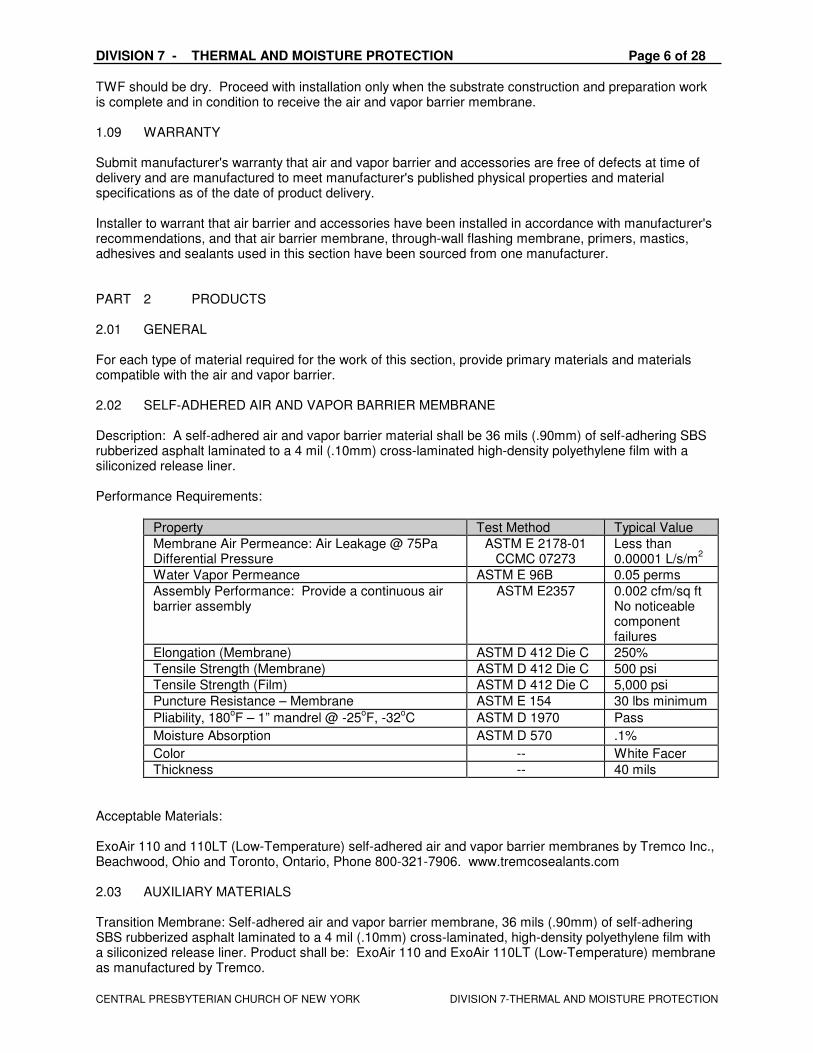
TWF should be dry. Proceed with installation only when the substrate construction and preparation work is complete and in condition to receive the air and vapor barrier membrane. 1.09 WARRANTY Submit manufacturer's warranty that air and vapor barrier and accessories are free of defects at time of delivery and are manufactured to meet manufacturer's published physical properties and material specifications as of the date of product delivery. Installer to warrant that air barrier and accessories have been installed in accordance with manufacturer's recommendations, and that air barrier membrane, through-wall flashing membrane, primers, mastics, adhesives and sealants used in this section have been sourced from one manufacturer. PART 2 PRODUCTS 2.01 GENERAL For each type of material required for the work of this section, provide primary materials and materials compatible with the air and vapor barrier. 2.02 SELF-ADHERED AIR AND VAPOR BARRIER MEMBRANE Description: A self-adhered air and vapor barrier material shall be 36 mils (.90mm) of self-adhering SBS rubberized asphalt laminated to a 4 mil (.10mm) cross-laminated high-density polyethylene film with a siliconized release liner. Performance Requirements:
Property Test Method Typical Value
Membrane Air Permeance: Air Leakage @ 75Pa Differential Pressure
ASTM E 2178-01 CCMC 07273
Less than 0.00001 L/s/m
2
Water Vapor Permeance ASTM E 96B 0.05 perms
Assembly Performance: Provide a continuous air barrier assembly
ASTM E2357 0.002 cfm/sq ft No noticeable component failures
Elongation (Membrane) ASTM D 412 Die C 250%
Tensile Strength (Membrane) ASTM D 412 Die C 500 psi
Tensile Strength (Film) ASTM D 412 Die C 5,000 psi
Puncture Resistance – Membrane ASTM E 154 30 lbs minimum
Pliability, 180oF – 1” mandrel @ -25
oF, -32
oC ASTM D 1970 Pass
Moisture Absorption ASTM D 570 .1%
Color -- White Facer
Thickness -- 40 mils
Acceptable Materials: ExoAir 110 and 110LT (Low-Temperature) self-adhered air and vapor barrier membranes by Tremco Inc., Beachwood, Ohio and Toronto, Ontario, Phone 800-321-7906. www.tremcosealants.com 2.03 AUXILIARY MATERIALS Transition Membrane: Self-adhered air and vapor barrier membrane, 36 mils (.90mm) of self-adhering SBS rubberized asphalt laminated to a 4 mil (.10mm) cross-laminated, high-density polyethylene film with a siliconized release liner. Product shall be: ExoAir 110 and ExoAir 110LT (Low-Temperature) membrane as manufactured by Tremco.
DIVISION 7 - THERMAL AND MOISTURE PROTECTION Page 7 of 28
CENTRAL PRESBYTERIAN CHURCH OF NEW YORK DIVISION 7-THERMAL AND MOISTURE PROTECTION
Flashing Membrane: Self-adhered through-wall flashing membrane, 32 mils (.80mm) of self-adhering SBS rubberized asphalt laminated to a 8 mil (.20mm) cross-laminated, high-density polyethylene film with a
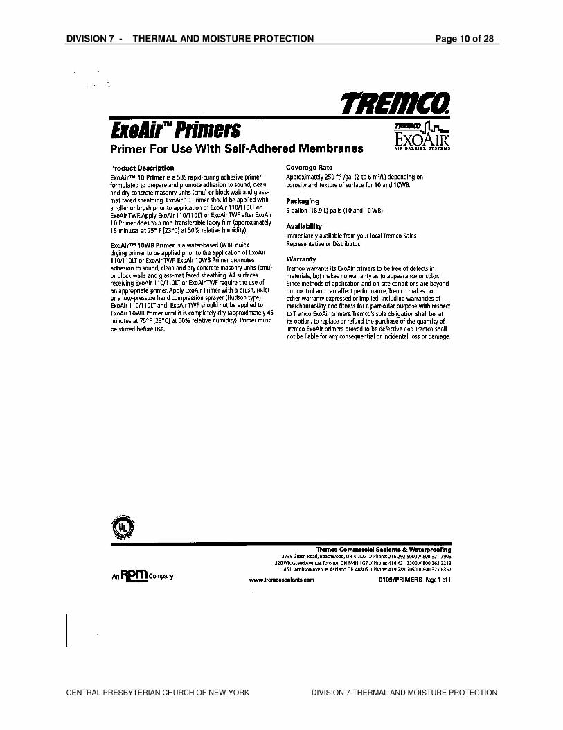
siliconized release liner. Product shall be: ExoAir TWF (Thru-Wall Flashing) membrane as manufactured by Tremco. Primary, Transition and Flashing Membrane Primer: Water-based liquid primer for extruded polystyrene,
concrete, masonry, gypsum sheathing, wood, metal, and painted substrates. Product shall be: ExoAir 10 WB Primer as manufactured by Tremco. Primary, Transition and Flashing Membrane Primer: Solvent-based liquid primer for concrete, masonry,
gypsum sheathing, wood, metal, and painted substrates. Product shall be: ExoAir 10 Primer as manufactured by Tremco. Butyl-based Self-Adhered Membrane: Transition between air and vapor barrier membrane and TPO or EPDM membranes. Mastic: Liquid mastic for sealing around brick ties, penetrations and lap and T-joints. Product shall be: ExoAir Termination Mastic, as manufactured by Tremco. Stainless-Steel Sheet Flashing: ASTM A167, Type 304, soft annealed, with No. 2D finish; minimum, 0.0156 inch (0.4 mm) thick. 3.01 EXAMINATION The installer shall examine conditions of substrates, areas and other conditions under which air barrier systems will be applied for compliance with requirements. Verify that surfaces and conditions are suitable prior to commencing work of this section. Notify the contractor in writing of circumstances detrimental to the proper completion of the work. Do not proceed with installation until unsatisfactory conditions have been corrected.
A. Ensure that:
1. surfaces are sound, dry, even, and free of oil, grease, dirt, excess mortar or other contaminants.
2. concrete surfaces are cured and dry, smooth without large voids, spalled areas or sharp protrusions. Allow new concrete to cure for a minimum 7 days.
3. masonry joints are flush and completely filled with mortar, and all excess mortar sitting on masonry ties has been removed.
4. ensure that the exterior sheathing panels are sufficiently stabilized with corners and
edges fastened with appropriate screws. B. Verify substrate is visibly dry and free of moisture. C. Notify Architect in writing of anticipated problems using air barrier over substrate.
3.02 SURFACE PREPARATION Clean, prepare and treat substrates according to manufacturers' written instructions. Surfaces to be coated must be clean, smooth, firm, free of dust, mud, loose mortar, wires, fins or any other substance that might prevent placement and bonding of membrane.
Mask off surrounding surfaces to prevent accidental coating by primers and mastics.
Remove contaminants such as grease, oil and wax from exposed surfaces. Use repair materials and methods that are acceptable to manufacturer of the self-adhered membrane.
Prime areas to be detailed and allow to cure. Ensure exterior sheathing panels and other substrates receiving ExoAir 110/110LT and ExoAir TWF receive an adequate amount of primer to achieve required bond to substrate. Exterior sheathing panels may require increased usage rates for ExoAir 10 Primer and ExoAir 10 WB Primer and/or multiple coats, allowing for complete drying between coats, to achieve required bond to substrate.

DIVISION 7 - THERMAL AND MOISTURE PROTECTION Page 8 of 28
CENTRAL PRESBYTERIAN CHURCH OF NEW YORK DIVISION 7-THERMAL AND MOISTURE PROTECTION
Masonry Substrates: Repair any cracks, voids, and unfilled mortar joints with non-shrinking grout. 3.03 INSTALLATION Refer to manufacturer’s literature for recommendations on installation.
Prior to the installation of ExoAir 110/110LT and ExoAir TWF, prime area to be detailed using ExoAir 10 Primer or ExoAir 10 WB Primer and allow to dry. Ensure gypsum sheathing and other substrates receiving ExoAir 110/110LT and ExoAir TWF receive an adequate amount of ExoAir 10 Primer or ExoAir 10 WB Primer and/or multiple coats, allowing for complete drying between coats, to achieve required bond to substrate. Application of Transition and Through-Wall Flashing Membranes: Apply ExoAir 110/110LT transition membrane (narrow widths used for detailing), and ExoAir TWF through-wall flashing membranes, before or after application of ExoAir 110/110LT (used for primary wall surface) so that the membrane assemblies create a shingle effect from top of the building to the bottom. Install transition membranes at all beams, columns, joints and all windows, doors and penetrations as indicated in detail drawings. Overlap all edge seams a minimum of 2” (50mm) and end laps a minimum of 5” (128mm); stagger all end laps.
Use Spectrem 1 or other pre-approved Tremco sealant to connect window and curtain wall systems to ExoAir 110/110LT or ExoAir TWF.
Use transition membranes to tie into window and doorframes, spandrel panels, floor intersections and changes in substrates. When installing ExoAir TWF, trim bottom edge of ExoAir TWF ½” (13mm) back from exposed face of the wall. ExoAir TWF shall not be permanently exposed to sunlight. Bring ExoAir 110/110LT and ExoAir TWF a minimum of 3” (75mm) onto wall, window, door frame and other substrates. Apply transition and through-wall flashing membranes in appropriate lengths and in such a manner as to ensure continuity of the entire air barrier assembly. At through-wall flashings, provide an additional 6” (152mm) wide strip of ExoAir TWF to seal top of through-wall flashing to ExoAir 110/110LT installed on substrate. Seal top edge of ExoAir TWF with ExoAir Termination Mastic. Tool the ExoAir Termination Mastic to ensure it is worked into the surface. Use pre-cut, easily handled lengths for each location. Remove release paper, position membranes carefully before placing them against the surface. Use a roller to apply pressure to the entire surface to remove all air pockets and assure positive contact to the substrate. Apply ExoAir Termination Mastic at all penetrations, lap joints not oriented to shed water, and T-joints.
Prior to completion of the air barrier project work or at the end of each work day, apply ExoAir Termination Mastic to the top edge seam of ExoAir 110/110LT or ExoAir TWF. Tool the ExoAir Termination Mastic to ensure it is worked into the surface.
Coordinate installation of the air barrier system with the roofing trade to ensure continuity / compatibility with the roofing system at this critical transition area. Roofing system should be capped and sealed prior to installation of the air barrier product to prevent moisture on interior and exterior side of the walls that will be treated. Connect the air barrier membrane to adjacent parts of the building envelope such as the roof membrane air barrier, below-grade wall, window and curtain wall systems, and other parts of the building envelope. Application on Substrates with Pre-Applied Brick Ties (typically CMU – Concrete Masonry Units): After detailing is complete and wall surface is primed, begin applying ExoAir 110/110LT (typically 18” widths) horizontally at base of wall, with top edge seam of each section meeting the bottom edge of the masonry brick ties. Overlap the next higher sections on the previous section a minimum of 2” (50mm). To do this, make a vertical cuts in the higher sections at the location of the brick ties. Use a roller to apply pressure to the entire surface to remove all air pockets and assure positive contact to the substrate. Apply ExoAir Termination Mastic at all penetrations, lap joints not oriented to shed water, and T-joints, so that there are no passages remaining for air infiltration/exfiltration, water vapor transmission or water penetration.
DIVISION 7 - THERMAL AND MOISTURE PROTECTION Page 9 of 28
CENTRAL PRESBYTERIAN CHURCH OF NEW YORK DIVISION 7-THERMAL AND MOISTURE PROTECTION
Application on Substrates with Post-Applied Brick Ties (typically exterior sheathing): After detailing is complete and wall surface is primed, apply ExoAir 110/110LT horizontally or vertically. Apply ExoAir Termination Mastic at all penetrations, lap joints not oriented to shed water, and T-joints, so that there are no passages remaining for air infiltration/exfiltration, water vapor transmission or water penetration.
Inspect the ExoAir110/110LT and ExoAir TWF membranes before covering and repair any punctures or damaged areas. Make repairs with ExoAir 110/110LT or ExoAir TWF as appropriate, or ExoAir Termination Mastic, extending repair material a minimum of 4” (100mm) beyond the puncture or damage.
3.04 PROTECTION AND CLEANING Remove any masking materials after installation. Clean spillage and soiling on adjacent construction that will be exposed in the finished work using cleaning agents and procedures recommended by manufacturer of the affected construction. Protect membranes to avoid damage from other trades, and construction materials during subsequent operations. Insulation and/or protection products may be installed after all membranes have cured. Schedule work so that the air and vapor barrier system is covered as soon as possible after installation. If the air and vapor barrier system cannot be covered within 30 days after installation, apply temporary UV protection such as dark plastic sheet or tarpaulins or contact Tremco for additional recommendations.
DIVISION 7 - THERMAL AND MOISTURE PROTECTION Page 10 of 28
CENTRAL PRESBYTERIAN CHURCH OF NEW YORK DIVISION 7-THERMAL AND MOISTURE PROTECTION
DIVISION 7 - THERMAL AND MOISTURE PROTECTION Page 11 of 28
CENTRAL PRESBYTERIAN CHURCH OF NEW YORK DIVISION 7-THERMAL AND MOISTURE PROTECTION
END OF SECTION 07271 07272 AIR AND VAPOR BARRIER MEMBRANE
Fluid-Applied Membrane Air Barriers
EXOAIR 120 AIR AND VAPOR BARRIER MEMBRANE PART 1 GENERAL 1.01 RELATED DOCUMENTS Drawings and general provisions of the Contract, including General and Supplementary Conditions and Division 1 Specification Sections, apply to this Section. 1.02 SUMMARY
B. The work of this section includes, but is not limited to, the following: materials and installation methods for fluid-applied air and vapor barrier membrane system located in the non-accessible part of the wall. Materials and installation methods to bridge and seal the following air leakage pathways and gaps: connections of the walls to the roof air barrier, connections of the walls to the foundations, seismic and expansion joints, openings and penetrations of window frames, store front, and curtain wall, barrier precast cast and other envelope systems, door frames, piping, conduit, duct and similar penetrations, masonry ties, screws, bolts and similar penetrations. All other air leakage pathways in the building envelope.
B. Related Sections: Other specification sections that directly relate to the works of this section include, but are not limited to, the following: Section 03300 – Cast-In-Place Concrete Section 04200 – Masonry Section 07100 – Dampproofing Section 07200 – Insulation Section 07530 – Roof Membrane [and Vapor Retarder] Section 07600 – Flashing and Sheet Metal Section 07900 – Joint Sealers Section 08810 – Glazing
Section 08410 – Aluminum Entrances and Storefronts Section 09250 – Gypsum Sheathing 1.03 PERFORMANCE REQUIREMENTS Provide an air and vapor barrier constructed to perform as a continuous air and vapor barrier, and as liquid water drainage plane flashed to discharge any incidental condensation or water penetration. 1304.3.1 Air Barriers: The building envelope shall be designed and constructed with a continuous air barrier to control air leakage into, or out of the conditioned space. An air barrier shall also be provided for interior partitions between conditioned space and space designed to maintain temperature or humidity levels which differ from those in the conditioned space by more than 50% of the difference between the conditioned space and design ambient conditions. The air barrier shall have the following characteristics:
5. It must be continuous, with all joints made airtight.
DIVISION 7 - THERMAL AND MOISTURE PROTECTION Page 12 of 28
CENTRAL PRESBYTERIAN CHURCH OF NEW YORK DIVISION 7-THERMAL AND MOISTURE PROTECTION
6. It shall have an air permeability not to exceed 0.004 cfm/ft2 under a pressure differential of 0.3 in. water. (1.57 psf.) (equal to 0.02 L/s/m2 @ 75 Pa.) when tested in accordance with ASTM E2178-01.
7. It shall be capable of withstanding positive and negative combined design wind, fan and stack pressures on the envelope without damage or displacement, and shall transfer the load to the structure. It shall not displace adjacent materials under full load.
8. It shall be durable or maintainable. The air barrier shall be joined in an airtight and flexible manner to the air barrier material of adjacent systems, allowing for the relative movement of systems due to thermal and moisture variations and creep. Connection shall be made between:
H. Foundation and walls. I. Walls and windows or doors. J. Different wall systems. K. Wall and roof. L. Wall and roof over unconditioned space. M. Walls, floor and roof across construction, control and expansion joints. N. Walls, floors and roof to utility, pipe and duct penetrations.
1304.3.2 Air barrier penetrations: All penetrations of the air barrier and paths of air infiltration/exfiltration shall be made airtight. 1.04 REFERENCES The following standards and publications are applicable to the extent referenced in the text. The most recent version of these standards is implied unless otherwise stated. American Society for Testing and Materials (ASTM) A 167-96 Specification for Stainless and Heat-Resisting Chromium-Nickel Steel Plate, Sheet, and Strip C 836-95 Standard Specification for Cold Liquid Applied Waterproofing Membranes with a Separate Wearing Course D 412-87 Standard Test Methods for Rubber Properties in Tension D 1970-94 Standard Specification for Self-Adhering Polymer Modified Bituminous Sheet Materials Used as Steep Roofing Underlayment for Ice Dam Protection D 2000-98 Classification System for Rubber Products in Automotive Applications D 2939-94 Standard Test Methods for Emulsified Bitumens Used as Protective Coatings D 3767-92 Standard Practice for Rubber - Measurements of Dimensions E 96-95 Test Methods for Water Vapor Transmission of Materials E 2178-01 Standard Test Method for Air Permeance of Building Materials E 2357 Standard Test Method for Determining Air Leakage of Air Barrier Assemblies Canadian Construction Materials Centre CCMC Technical Guide 07273 Air Barrier Materials 1.05 SUBMITTALS Product Data: Submit manufacturer’s product data, installation instructions, and substrate preparation recommendations. Shop drawings: Show the locations and extent of air and vapor barrier system including details of typical conditions, intersections with other envelope systems and materials, membrane counter-flashings and details showing how gaps in the construction will be bridged and how miscellaneous penetrations such as conduits, pipes, etc. are sealed. Written documentation: Demonstrate the installer’s qualifications under the "Quality Assurance" article. Samples: Submit representative samples of the following for approval: Cured sample of the fluid-applied, transition, and through-wall flashing membranes, as well as certification by air and vapor barrier manufacturer that products supplied comply with local regulations controlling use of volatile organic compounds (VOC's).

DIVISION 7 - THERMAL AND MOISTURE PROTECTION Page 13 of 28
CENTRAL PRESBYTERIAN CHURCH OF NEW YORK DIVISION 7-THERMAL AND MOISTURE PROTECTION
1.06 QUALITY ASSURANCE Manufacturer: Air and vapor barrier materials shall be manufactured and marketed by a firm with a minimum of 20 years’ experience in the production and sales of waterproofing products. Manufacturers proposed for use, but not named in these specifications shall submit evidence of ability to meet all requirements specified. Installer: The installer shall demonstrate qualifications to perform the work of this Section by submitting the following: Written confirmation or certification from the air barrier manufacturer that the installer has been trained and is recognized by the manufacturer as suitable for the execution of the work. Installer must show evidence of adequate equipment and trained field personnel to successfully complete the project in a timely manner. Both the architect and the air barrier materials manufacturer must approve the installer’s credentials. Materials: Fluid-applied air and vapor barrier material shall be water-based and an elastomeric, single-component, polymer-modified, asphaltic membrane, and contain less than 100 gm/l VOC. Pre-Installation Conference: A pre-installation conference shall be held prior to commencement of field operations per Section 01200 to establish procedures to maintain optimum working conditions and to coordinate this work with related and adjacent work. Agenda for meeting shall include but not be limited to the following:
Review of submittals Review of surface preparation, minimum curing period and installation procedures Review of special details and flashings Sequence of construction, responsibilities and schedule for subsequent operations Review of mock-up requirements Review of inspection, testing, protection and repair procedures
Manufacturer’s Representative: Make arrangements necessary to have a trained representative of the manufacturer to review installation procedures. Notify manufacturer's representative not less than 72 hours before meeting is to be held. Mock-up: Prior to installation of the air and vapor barrier system a field-constructed mock-up shall be provided under the provisions of Section [01340 – Shop Drawings, Product Data, Samples and Mock-ups] to verify details and tie-ins and to demonstrate the required quality of materials and installation. Construct a typical exterior wall section, 8 feet long and 8 feet wide, incorporating back-up wall, cladding, window and doorframe and sill, insulation, flashing and any other critical junction (roof, foundation, etc). Allow 24 hours for inspection and testing of mock-up before proceeding with air and vapor barrier work. Mock-up may remain as part of the work. Inspection and Testing: Cooperate and coordinate with the Owner’s inspection and testing agency. Do not cover any installed air and vapor barrier membrane until any required inspections, testing, and approvals have been completed. 1.07 DELIVERY, STORAGE AND HANDLING Deliver materials and products in labeled packages. Store and handle in strict compliance with manufacturer’s instructions, recommendations and material safety data sheets. Protect from damage from sunlight, weather, excessive temperatures and construction operations. Remove damaged material
from the site and dispose of in accordance with applicable regulations. Store ExoAir 120 off the ground/floor at an ambient temperature above 50
OF. Do not freeze. Protect the drums from direct
sunlight. If ExoAir 120 is delivered in totes, follow manufacturers' instructions for handling, stacking and storage of totes. Sequence deliveries to avoid delays while keeping on-site storage at a minimum. 1.08 PROJECT CONDITIONS Apply air and vapor barrier within the weather conditions and the range of ambient and substrate temperatures specified by air and vapor manufacturer. Do not apply to a wet substrate. Damp
DIVISION 7 - THERMAL AND MOISTURE PROTECTION Page 14 of 28
CENTRAL PRESBYTERIAN CHURCH OF NEW YORK DIVISION 7-THERMAL AND MOISTURE PROTECTION
substrates, determined by rubbing a hand across the substrate and seeing no water/dampness on the
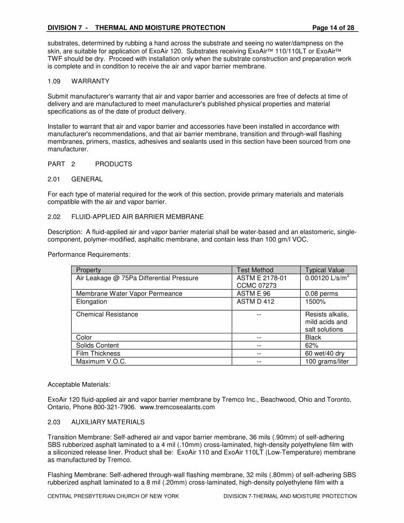
skin, are suitable for application of ExoAir 120. Substrates receiving ExoAir 110/110LT or ExoAir TWF should be dry. Proceed with installation only when the substrate construction and preparation work is complete and in condition to receive the air and vapor barrier membrane. 1.09 WARRANTY Submit manufacturer's warranty that air and vapor barrier and accessories are free of defects at time of delivery and are manufactured to meet manufacturer's published physical properties and material specifications as of the date of product delivery. Installer to warrant that air and vapor barrier and accessories have been installed in accordance with manufacturer's recommendations, and that air barrier membrane, transition and through-wall flashing membranes, primers, mastics, adhesives and sealants used in this section have been sourced from one manufacturer. PART 2 PRODUCTS 2.01 GENERAL For each type of material required for the work of this section, provide primary materials and materials compatible with the air and vapor barrier. 2.02 FLUID-APPLIED AIR BARRIER MEMBRANE Description: A fluid-applied air and vapor barrier material shall be water-based and an elastomeric, single-component, polymer-modified, asphaltic membrane, and contain less than 100 gm/l VOC. Performance Requirements:
Property Test Method Typical Value
Air Leakage @ 75Pa Differential Pressure ASTM E 2178-01 CCMC 07273
0.00120 L/s/m2
Membrane Water Vapor Permeance ASTM E 96 0.08 perms
Elongation ASTM D 412 1500%
Chemical Resistance -- Resists alkalis, mild acids and salt solutions
Color -- Black
Solids Content -- 62%
Film Thickness -- 60 wet/40 dry
Maximum V.O.C. -- 100 grams/liter
Acceptable Materials: ExoAir 120 fluid-applied air and vapor barrier membrane by Tremco Inc., Beachwood, Ohio and Toronto, Ontario, Phone 800-321-7906. www.tremcosealants.com 2.03 AUXILIARY MATERIALS Transition Membrane: Self-adhered air and vapor barrier membrane, 36 mils (.90mm) of self-adhering SBS rubberized asphalt laminated to a 4 mil (.10mm) cross-laminated, high-density polyethylene film with a siliconized release liner. Product shall be: ExoAir 110 and ExoAir 110LT (Low-Temperature) membrane as manufactured by Tremco. Flashing Membrane: Self-adhered through-wall flashing membrane, 32 mils (.80mm) of self-adhering SBS rubberized asphalt laminated to a 8 mil (.20mm) cross-laminated, high-density polyethylene film with a
DIVISION 7 - THERMAL AND MOISTURE PROTECTION Page 15 of 28
CENTRAL PRESBYTERIAN CHURCH OF NEW YORK DIVISION 7-THERMAL AND MOISTURE PROTECTION
siliconized release liner. Product shall be: ExoAir TWF (Thru-Wall Flashing) membrane as manufactured by Tremco. Transition and Flashing Membrane Primer: Water-based liquid primer for extruded polystyrene, concrete,
masonry, gypsum sheathing, wood, metal, and painted substrates. Product shall be: ExoAir 10 WB Primer as manufactured by Tremco. Transition and Flashing Membrane Primer: Solvent-based liquid primer for concrete, masonry, gypsum
sheathing, wood, metal, and painted substrates. Product shall be: ExoAir 10 Primer as manufactured by Tremco. Butyl-based Self-Adhered Membrane: Transition between air and vapor barrier membrane and TPO or EPDM membranes. Mastic: Liquid mastic for sealing around brick ties, penetrations and lap and T-joints. Product shall be: ExoAir Termination Mastic, as manufactured by Tremco. Stainless-Steel Sheet Flashing: ASTM A167, Type 304, soft annealed, with No. 2D finish; minimum, 0.0156 inch (0.4 mm) thick. PART 3 INSTALLATION INSTRUCTIONS Refer to the manufacturer’s recommendations for complete installation instructions. Manufacturer’s instructions should be strictly adhered to including the following:
1. Cut the metal adapter to the appropriate length. Remove the release paper on the back of the metal adaptor and position the adaptor on the window and/or wall support member. The butyl tape will temporarily hold the adaptor in position until the screws are installed and will provide a secondary seal between the adaptor and the window/wall frame
a. Clean the adaptor and window frame with the IPA two-cloth method where the metal adaptor will make contact
2. Spectrem 1 Silicone Sealant should be applied between the metal adaptor and the window frame to ensure a firm, continuous seal.
3. The Silicone Rubber Extrusion is inserted into the adaptor’s race 4. The Spectrem 1 Silicone Sealant will permanently affix the Silicone Rubber Extrusion in the
assembly 5. The Silicone Rubber Corners are inserted into the race last 6. The lap joints are sealed next. The perimeter seal is done last to permanently bond the Silicone
Rubber Extrusion to the ExoAir 110 sheet. 3.01 EXAMINATION The installer shall examine conditions of substrates, areas and other conditions under which air barrier systems will be applied for compliance with requirements. Verify that surfaces and conditions are suitable prior to commencing work of this section. Notify the contractor in writing of circumstances detrimental to the proper completion of the work. Do not proceed with installation until unsatisfactory conditions have been corrected.
D. Ensure that:
1. surfaces are sound, dry, even, and free of oil, grease, dirt, excess mortar or other contaminants.
2. concrete surfaces are cured and dry, smooth without large voids, spalled areas or sharp protrusions.
3. masonry joints are flush and completely filled with mortar, and all excess mortar sitting on masonry ties has been removed.
E. Verify substrate is visibly dry and free of moisture. F. Notify Architect in writing of anticipated problems using air barrier over substrate.
3.02 SURFACE PREPARATION
DIVISION 7 - THERMAL AND MOISTURE PROTECTION Page 16 of 28
CENTRAL PRESBYTERIAN CHURCH OF NEW YORK DIVISION 7-THERMAL AND MOISTURE PROTECTION
Clean, prepare and treat substrates according to manufacturers' written instructions. Surfaces to be coated must be clean, smooth, firm, free of dust, mud, loose mortar, wires, fins or any other substance that might prevent placement and bonding of a continuous film. Remove contaminants such as grease, oil and wax from exposed surfaces. Use repair materials and methods that are acceptable to manufacturer of the fluid-applied membrane. Exterior Sheathing Board Joints and Inside/Outside Corners: Ensure that the boards are sufficiently stabilized with corners and edges fastened with appropriate screws. Seal all joints, screws, etc with ExoAir Termination Mastic and allow sufficient time for the ExoAir Termination Mastic to fully cure before application of ExoAir 120. Detail inside and outside corners as above. Alternate Method - Exterior Sheathing Board Joints and Inside/Outside Corners: A second method of detailing these conditions can be used in place of the method discussed above. Prime area to be detailed using ExoAir 10 Primer or ExoAir 10 WB Primer and allow to dry. Ensure gypsum sheathing and other substrates receiving ExoAir 110/110LT receive an adequate amount of ExoAir 10 Primer or 10 WB Primer to achieve required bond to substrate. Apply a minimum 3” (75mm) width of ExoAir 110/110LT to the area to be treated. Use a roller to apply pressure to the entire surface to remove all air pockets and assure positive contact to the substrate. Masonry Substrates: Repair any cracks, voids, and unfilled mortar joints with non-shrinking grout. 3.03 INSTALLATION Refer to manufacturer’s literature for recommendations on installation. Application of Transition and Through-Wall Flashing Membranes: Apply ExoAir 110/110LT transition, and ExoAir TWF through-wall flashing membranes, before or after application of ExoAir 120 membrane so that the membrane assemblies create a shingle effect from top of the building to the bottom. Prior to the installation of ExoAir 110/110LT and ExoAir TWF, prime area to be detailed using ExoAir 10 Primer or ExoAir 10 WB Primer and allow to dry. Ensure exterior sheathing and other substrates receiving ExoAir 110/110LT receive an adequate amount of primer and/or multiple coats, allowing for complete drying between coats, to achieve required bond to substrate. Install transition membranes at all beams, columns, joints and all windows, doors and penetrations as indicated in detail drawings, overlapping edge seams a minimum of 2” (50mm) and end laps a minimum of 4” (128mm).
Use Spectrum 1 or other pre-approved Tremco sealant to connect window and curtain wall systems to ExoAir 110/110LT transition membranes or ExoAir TWF.
Use transition membranes to tie into window and doorframes, spandrel panels, floor intersections and changes in substrates. When installing ExoAir TWF, trim bottom edge of ExoAir TWF ½” (13mm) back from exposed face of the wall. ExoAir TWF shall not be permanently exposed to sunlight. Bring ExoAir 110/110LT and ExoAir TWF a minimum of 3” (75mm) onto wall, window, door frame and other substrates. Apply transition and through-wall flashing membranes in appropriate lengths and in such a manner as to ensure continuity of the entire air barrier assembly. At through-wall flashings, provide an additional 6” (152mm) wide strip of ExoAir TWF to seal top of through-wall flashing to ExoAir 120 installed on substrate. Seal top edge of ExoAir TWF with ExoAir Termination Mastic. Tool the Termination Mastic to ensure it is worked into the surface. Use pre-cut, easily handled lengths for each location. Remove release paper, position membranes carefully before placing them against the surface. Use a roller to apply pressure to the entire surface to remove all air pockets and assure positive contact to the substrate. Seal the edge with ExoAir Termination Mastic. If a transition membrane is to be attached to ExoAir 120, ExoAir 120 must be cured (16-24 hours and/or firm and dry to the touch) prior to installing the transition membrane.
Prior to completion of the air barrier project work or at the end of each work day, apply ExoAir Termination Mastic to the top edge seam of ExoAir 110/110LT or ExoAir TWF. Tool the ExoAir Termination Mastic to ensure it is worked into the surface.
DIVISION 7 - THERMAL AND MOISTURE PROTECTION Page 17 of 28
CENTRAL PRESBYTERIAN CHURCH OF NEW YORK DIVISION 7-THERMAL AND MOISTURE PROTECTION
Coordinate installation of the air barrier system with the roofing trade to ensure continuity / compatibility with the roofing system at this critical transition area. Roofing system should be capped and sealed prior to installation of the air barrier product to prevent moisture on interior and exterior side of the walls that will be treated. Connect the air barrier membrane to adjacent parts of the building envelope such as the roof membrane air barrier, below-grade wall, window and curtain wall systems, and other parts of the building envelope. Application of Fluid-Applied Membrane: Spray a continuous uniform film of ExoAir 120 at 60 mils (1.5mm) min. wet film thickness using multiple, overlapping passes. When spraying use a cross-hatching technique (alternating horizontal and vertical passes) to ensure even thickness and coverage. When spraying use high pressure, airless spray equipment approved by Tremco. Seal all brick-ties and other penetrations with ExoAir 120 or ExoAir Termination Mastic as appropriate and as work progresses. Carry ExoAir 120 a minimum of 3” (75mm) onto the ExoAir 110/110LT transition and ExoAir TWF membranes. Review final ExoAir 120 application to ensure all substrates have been fully coated, and that there are no passages remaining for air infiltration / exfiltration, water vapor transmission or water penetration.
Inspect the ExoAir 120 membrane before covering and repair any punctures or damaged areas with ExoAir 120, ExoAir Termination Mastic or other pre-approved Tremco sealant, extending repair material a minimum of 4” (152mm) beyond the puncture or damage.
Inspect ExoAir 110/110LT and ExoAir TWF membranes before covering and repair any punctures or damaged areas. Make repairs with ExoAir 110/110LT or ExoAir TWF as appropriate, or ExoAir Termination Mastic, extending either repair material a minimum of 4” (152mm) beyond the puncture or damage. 3.04 PROTECTION AND CLEANING Remove any masking materials after installation. Clean spillage and soiling on adjacent construction that will be exposed in the finished work using cleaning agents and procedures recommended by manufacturer of the affected construction. Protect membranes to avoid damage from other trades, and construction materials during subsequent operations. Insulation and/or protection products may be installed after all membranes have cured (16-24 hours and/or firm and dry to the touch). Schedule work so that the air and vapor barrier system is covered as soon as possible after installation. If the air and vapor barrier system cannot be covered within 30 days after installation, apply temporary UV protection such as dark plastic sheet or tarpaulins or contact Tremco for additional recommendations. END OF SECTION 07272

DIVISION 7 - THERMAL AND MOISTURE PROTECTION Page 18 of 28
CENTRAL PRESBYTERIAN CHURCH OF NEW YORK DIVISION 7-THERMAL AND MOISTURE PROTECTION
07530-2 TPO MEMBRANE ROOFING SYSTEM - ADHERED TYPE PART 1 GENERAL A. SYSTEM DESCRIPTION
1. Extent of membrane roofing is indicated on drawings and is hereby defined to include non-traffic-bearing sheet membrane system intended for weather exposure as primary roofing.
2. Type: TPO roofing fully adhered to substrate. 3. Roof Insulation related to flexible sheet roofing is specified in this section. 4. Manufacturer: Obtain primary single-ply membrane sheet roofing from a single manufacturer.
Provide secondary materials as recommended by manufacturer of primary materials. 5. Related work specified elsewhere:
a. Carpentry - wood blocking and nailers: Division 6. b. Flashing and sheet metal - weather protection to base flashings: Elsewhere in Division 7 c. Roof accessories - skylights, prefabricated curbs, access hatches: elsewhere in Division
7. d. Roof drains, curbs for equipment: Division 15.
B. REFERENCED STANDARDS
1. ASTM C 518-85 – Standard Test Method for Steady-State Heat Flux Measurements and Thermal Transmission Properties by Means of the Heat Flow Meter Apparatus; 1985.
2. ASTM C 578-87a – Standard Specification for Pre-formed Cellular Polystyrene Thermal Insulation, 1987.
3. ASTM D 4637-87 – Standard Specification for Vulcanized Rubber Sheet Used in Single-Ply roof Membrane, 1987.
4. ASTM E 84-89a – Standard Test Method for Surface Burning Characteristics of Building Materials, 1989.
5. FMS 1-28 – Insulated Steel Deck; Factory Mutual System, 1983. 6. FM P7825 – Approval Guide 1991; Factory Mutual System; 1991 (with Supplements I and II).
C. SUBMITTALS 1. Shop Drawings: Submit roofing membrane layout drawings showing seam locations, specific
roofing details illustrating relationship with adjacent construction, and flashing details at roof perimeter, and roof penetrations. a. Submit installation diagrams and instructions for tapered insulation system. b. Product Data: Submit specifications, installation instructions and general
recommendations from manufacturers of single ply roofing system materials. Include data substantiating compliance of materials.
2. Samples: a. Walkway mats: Submit 6 product sample, 6” square.
D. QUALITY ASSURANCE
1. Installer Qualifications: A company approved or licensed by the roofing materials manufacturer and which has completed at least 20 previous installations of roofing material similar to the type included in this section.
2. Installer Certification: Furnish to the Architect, before roofing contract award, written documentation that installer is manufacturer certified to install roofing systems of the type included in this section.
3. Installer Field Supervisions: Installer shall maintain full-time supervisor/foreman on project site during times in which roofing work is in progress. Supervisor shall have a minimum of 5 years’ experience in roofing work similar in nature and scope to the specified roofing.
4. Factory Mutual System Classification: Provide roof system materials and roof system assembly which have tested and are listed in Factory Mutual System’s “Approval Guide” as acceptable for Class I roof deck construction.
a. Roof material packaging shall have FM Classification marking. b. Provide roof system, including insulation and fasteners, rated by FM for Class I-90 wind
uplift. 5. Begin roofing installation when weather conditions are within acceptable limits according to
manufacturer’s installation instructions. E. PROJECT CONDITIONS Begin roofing installation when weather conditions are within acceptable limits according to
manufacturer’s installation instructions.
DIVISION 7 - THERMAL AND MOISTURE PROTECTION Page 19 of 28
CENTRAL PRESBYTERIAN CHURCH OF NEW YORK DIVISION 7-THERMAL AND MOISTURE PROTECTION
F. PRODUCT HANDLING 1. Deliver materials to project site in manufacturer’s unopened sealed containers or unopened
packages, with manufacturer’s labels intact. 2. Store materials in weather-protected environment, clear of ground and moisture.
a. Protect foam plastic insulation from direct sunlight exposure. G. WARRANTY
1. Manufacturer’s Membrane System Warranty: Submit manufacturer’s standard membrane system warranty, including flashing endorsement, signed by the manufacturer’s authorized official, guaranteeing to correct failures in product which may occur during the warranty period, without reducing or otherwise limiting any other rights to correction which the owner may have under the contract documents. a. Warranty Period: 20 years, starting from date of substantial completion.
PART 2 PRODUCTS A. ROOF SYSTEM
1. Project design is based on the following: FIRESTONE ULTRAPLY TPO MEMBRANE FULLY ADHERED
2. Manufacturers: Products of the following manufacturers, provided they comply with requirements will also be considered acceptable: a. Carlisle Roofing Company b. Or equal, prior approved by Architect.
3. Membrane a. Membrane Material: not less than 0.060 inch (60 mils) thick.
1) Color: Manufacturer’s standard white. d. Accessories: Roofing manufacturer’s standard accessories to suit project conditions and
fully adhered roof system installation. B. INSULATION
1. System Requirements: Minimum “R-value” at 75 degrees F, in accordance with ASTM C 518 after conditioning for 180 days: Use “in service” R value of 5.6 per inch thickness of polyisocyanurate insulation board products. a. Insulation Board to be laid in minimum 2 layers with joints staggered.
2. Acceptable Types: a. Polyisocyanurate foam: ASTM C 591. b. Facers: Manufacturer’s standard c. Acceptable Products for use:
1) ACFoam II; Atlas Energy Products. 2) ENRGY-1; NRG Barriers 3) Hy-Therm; Celotex Company 4) Iso-95+; Firestone Building Products Company 5) R-MAX; R-MAX Corporation
C. TAPERED INSULATION SYSTEM - WHERE SHOWN ON DRAWINGS
1. System Requirements: a. Minimum average “R-Value” in accordance with ASTM C 518 after conditioning: 4.17 at
75 degrees F. b. Minimum Slope: 1/4 inch per foot. c. Minimum Thickness: 0 inches at low points, unless otherwise noted. d. Maximum Thickness: As required per slope, unless otherwise noted.
2. Roof Insulation - Acceptable Types: a. Polyisocyanurate foam: ASTM C 591 b. Facers: Manufacturer’s standard c. Acceptable Products for use:
D. ROOF BOARD
1. System Requirements a. Minimum slope: 1/4” per foot. b. Applied on polyiso. Insulation with mechanical fasteners, per manufacturers
recommendations. 2. Acceptable types:
a. 1/4” Dens Deck Prime Roof board on horizontal surfaces. b. 1/2” Dens Deck Prime Roof board on vertical surfaces.
DIVISION 7 - THERMAL AND MOISTURE PROTECTION Page 20 of 28
CENTRAL PRESBYTERIAN CHURCH OF NEW YORK DIVISION 7-THERMAL AND MOISTURE PROTECTION
E. ACCESSORIES
1. General: Provide installation accessories as required for complete roofing system and as recommended by membrane manufacturer, including but not necessarily limited to: a. Seam adhesive (splice cement). b. Bonding adhesive. c. Seam sealant. d. Fasteners: Galvanized steel; plain or with factory-applied corrosion-resistant coating,
insulation type and thickness and for deck type. Provide fasteners which meet requirements for pull out resistance.
e. Termination bars: Plastic, hard rubber, or corrosion-resistant metal. f. Prefabricated penetration and corner flashings: Use to greatest extent possible
consistent with manufacturer’s recommendation. 2. Walkways: Pre-formed walkway mats: Molded reprocessed rubber, manufactured or
recommended by membrane manufacturer. Provide walkway mats around all four sides of all roof top equipment, whether shown on drawings or not.
3. Pre-formed Pipe Boot Flashings: Molded from same material as flexible flashings. Provide stainless steel band clamp for top edge.
PART 3 EXECUTION A. EXAMINATION
1. Verify that deck is clean, dry, smooth, and properly sloped for drainage. 2. Verify that roof deck construction meets roof system manufacturer’s minimum roof deck criteria for
the roof system to be installed. Correct substrate surfaces which are unacceptable to the installer, and are not in accordance with manufacturer’s installation instructions, before starting roofing application.
3. Verify that roof openings, penetrations, roof edges, and interruptions are properly set or braced and ready to receive roof system.
B. PREPARATION
1. Remove dirt, construction debris, and other material from the deck, which could prohibit proper roof membrane installation.
2. Install blocking, nailers, cants, reglets, and similar attachment devices as indicated or required. C. INSULATION INSTALLATION
1. General: a. Install according to manufacturer’s recommendations.
END OF SECTION 07530-2 07600 FLASHING AND SHEET METAL PART 1 GENERAL A. WORK INCLUDED
1. Metal flashing and counter flashing. 2. Valleys, sumps and scuppers. 3. Gravel stops, fascia units and trim. 4. Sheet metal expansion joints. 5. Elastic sheet flashing.
B. SUBMITTALS
1. Submit shop drawings for Architect’s approval, for all items this Section. 2. Drawings shall show profiles of pieces, attachment, and splices.
C. STANDARDS
1. Conform to the requirements of the “Architectural Sheet Metal Manual”, Latest Edition of the Sheet Metal and Air Conditioning Contractors National Association.
2. Form all metal shapes in shop with bending brake. 3. Conform to profiles and sizes shown on Drawings (where indicated).
D. GUARANTEE
1. Refer to roofing section for guarantee of flashings associated with roof system.
DIVISION 7 - THERMAL AND MOISTURE PROTECTION Page 21 of 28
CENTRAL PRESBYTERIAN CHURCH OF NEW YORK DIVISION 7-THERMAL AND MOISTURE PROTECTION
PART 2 PRODUCTS A. ZINC-COATED (GALVANIZED) STEEL SHEET
1. Material: ASTM A 526, 0.20 percent copper, 24 gage (0.0179 inch); ASTM A 525, designation G90 hot-dip galvanized, mill phosphatized.
2. Clips: Same material as flashing, except 22 gauge minimum. 3. Furnish shapes in 8 ft. lengths minimum. 4. Joints: Butt type, with 6” long splice plates of same profile as flashing piece. 5. Solder: 50/50 pig lead and block tin. 6. Exposed fasteners: shall have neoprene washers.
B. ELASTIC SHEET FLASHING/MEMBRANE
1. Manufacturer’s standard flexible, elastic black, non-reinforced, flashing sheet of 50 to 60 mils thickness, 50 to 70 Shore A hardness, 1200 psi tensile strength, minus 30 degrees F (minus 35 degrees C) brittleness.
2. Elastic Sheet: EPDM synthetic rubber. PART 3 EXECUTION A. METAL FLASHING GENERAL REQUIREMENTS
1. Install with butt type joints, with matching splice plate located and centered under joint. 2. Apply sealant between splice plate and each member. 3. Flashing shall spring tight against roofing. 4. No exposed anchoring permitted unless noted. 5. Allow for expansion of all pieces. 6. Splice plates shall not be secured to either member. 7. Finish work shall be tight, straight, with flat surfaces and even edges. 8. Install flashing into reglets with lead wedges and fill reglet with sealant. 9. Where galvanized flashing turns corner, miter and solder together. 10. Where expansion joints meet wall flashing, provide sheet metal covers, counterflashing, etc. as
required to provide watertight enclosure and to permit movement at expansion joint. 11. Coat back-side of fabricated sheet metal with 15-mil sulfur-free bituminous coating, SSPC-Paint
12, where required to separate metals from corrosive substrates including cementitious materials, wood or other absorbent materials; or provide other permanent separation.
END OF SECTION 07600 07612 STANDING SEAM METAL ROOFING PART 1 GENERAL A. DESCRIPTION OF WORK
1. Extend of standing seam metal roofing and flashing accessories is indicated on drawings and provisions of this section.
2. Types of work specified in this section include. a. Pre-formed metal panels. b. Related flashings and accessories c. Built-in gutter. d. Snow guards.
B. SUBMITTALS
1. Product Data: Submit manufacturer’s technical product data, and general installation recommendations for each product required. Include data substantiating that materials and performance comply with requirements.
2. Shop Drawings: Submit shop drawings showing layout of panels, details of edge conditions, joints, corners, panel profiles, clips, trim, flashing and special details.
3. Samples: For selection of colors, submit small sections of the same metal to be used in the work which have been finished to indicate the standard colors and standard textures available.
4. Panel applicator shall provide a ten-year weather-tightness warranty. 5. Panel manufacturer shall provide a 20-year non-prorated warranty for the paint finish covering
cracking, checking, blistering, peeling, flaking, chipping, chalking and fade. C. QUALITY ASSURANCE

DIVISION 7 - THERMAL AND MOISTURE PROTECTION Page 22 of 28
CENTRAL PRESBYTERIAN CHURCH OF NEW YORK DIVISION 7-THERMAL AND MOISTURE PROTECTION
1. Industry standards: Provide products which comply with applicable requirements of SMACNA “Architectural Sheet Metal Manual,” except as otherwise indicated.
2. Qualifications of Installers: Applicator shall have at least (3) years experience applying these types of materials on projects of similar scope and complexity.
3. UL wind uplift resistance classification: Roof assembly shall be classified as UL 90 as defined by UL 580 specifications.
4. Static air infiltration: completed roof system shall have a maximum of 0.06 CFM. sq. ft. with 6.24 PSF air differential as per ASTM E 283.
5. Water infiltration: No evidence of water penetration at an inward static air pressure differential of not less than 6.24 PSF and not more than 12.00 PSF as per ASTM E 331.
PART 2 PRODUCTS A. STANDING SEAM METAL ROOFING
1. Manufacturer: FIRESTONE UNA-CLAD UC -4 (18” max. panel) -Products of the following manufacturers, provided they comply with requirements will also be considered acceptable:
a. AEP-Span: b. Berridge –
2. Standing Seam Sheet Metal Roofing: a. Material: 24 gauge zinc-Coated Steel Sheet: ASTMA A 526, G90 coating, or galvalume
ASTM – A792. b. Panel Finish: Topcoat of Kynar 500 finish, COLOR – DARK IVY - Underside of panels
shall be protected by an epoxy type wash-coat with a dry film thickness of 0.3 mils. 3. Texture: flat rib profile or pencil rib profile 4. Miscellaneous Materials:
a. Concealed Fastening Clips: Same metal as item fastened or other non-corrosive metal as recommended by manufacturer, spaced at UL 90 requirements.
b. Fasteners: Type and size standard with manufacturer for product and application indicated.
c. Underlayment: CLAD-GARD R UNDERLAYMENT OR CLAD-GARD MA UNDERLAYMENT or approved equal.
d. Flashing and accessories: Fabricated from sheet metal matching roof panels in accordance with standard SMACNA procedures and details.
B. SNOW GUARDS
1. Manufacturer: Subject to compliance with requirements, provide product of the following or approved equal: a. Snowjax, Mechanicsburg, PA. (717-697-1900). b. Polar Blox, Hollsopie, PA. (800-298-4328).
2. Provide polycarbonate snow guards, one per standing seam pan. 3. Attachment: Adhesive per manufacturer’s recommendation. Fasteners thru the panel are not
acceptable. C. WARRANTY PERIOD: 20 years, starting from date of substantial completion.
PART 3 EXECUTION A. INSTALLATION
1. Conform to standards set forth in the SMACNA architectural sheet metal manuals. 2. Comply with manufacturer’s written installation instructions and recommendations. 3. Install panels plumb, level and straight with seams and ribs parallel, conforming to the design as
indicated. 4. Install panels so they are weather-tight - without waves, warps, buckles or distortions. Allow for
expansion and contraction. 5. Anchor products included in this section securely to structural substrates, adequate to withstand
lateral and thermal stresses as well as inward and outward loading pressures. 6. Caulk all flashing and panel joints that require caulking to prevent water penetration. 7. Ribbed pans will be vertically broken under ridges and hooked at the eaves to insure weather-
tightness. 8. Remove masking on trim flashings immediately after installation. 9. Hem all raw edges on flashings. 10. Install snow guards at low end of standing seam sheet metal panel, approximately 12-inches
above edge of roof. Center between seams. END OF SECTION 07612
DIVISION 7 - THERMAL AND MOISTURE PROTECTION Page 23 of 28
CENTRAL PRESBYTERIAN CHURCH OF NEW YORK DIVISION 7-THERMAL AND MOISTURE PROTECTION
07620 METAL FASCIA AND COPINGS PART 1 GENERAL A. DESCRIPTION OF WORK
1. Extent of metal fascia and copings is indicated on drawings and provisions of this section. 2. Types of work specified in this section include.
a. Aluminum copings. 3. Sheet metal and flashings not part of fascia and coping systems included in this section are
specified in another Division-7 section. B. QUALITY ASSURANCE
1. Industry standards: Provide products which comply with applicable requirements of SMACNA “Architectural Sheet Metal Manual,” except as otherwise indicated.
C. SUBMITTALS
1. Product Data: Submit manufacturer’s technical product data, installation instructions and general recommendations for each fascia and coping product required. Include data substantiating that materials and performance comply with requirements.
2. Samples: For selection of colors submit manufacturer’s color charts consisting of small sections of the same metal to be used in the work which have been finished to indicate the full range and quality of standard colors or color ranges and of standard textures available.
D. JOB CONDITIONS
1. Coordinate work of this section with adjoining work for proper sequencing of each installation to ensure best possible weather resistance and protection of materials and finishes against damage.
PART 2 PRODUCTS A. MATERIALS
1. Aluminum Materials: a. Aluminum Sheet: Alloy and temper recommended by manufacturer for use intended and
finish indicated, and with strength and durability of properties of ASTM B 209 for 5005-H15.
2. Steel Materials: Zinc-Coated Steel Sheet: ASTM A 526, G90 coating. 3. Miscellaneous Materials:
a. Exposed Fasteners: Stainless steel, non-magnetic, of type and size standard with manufacturer for product and application indicated. Match finish of exposed heads with material being fastened.
b. Concealed Fasteners: Same metal as item fastened or other non-corrosive metal as recommended by manufacturer.
c. Mastic Sealant: Polyisobutylene; non-hardening, non-skinning, non-drying, non-migration sealant.
d. Foam Rubber Seal: Manufacturer’s standard foam. e. Adhesives: type recommended by manufacturer for substrate and project conditions, and
formulated to withstand minimum 60 psf uplift force. B. FABRICATIONAL, GENERAL
1. Provide fascia and coping which are designed and fabricated to fit application indicated and to weather resistance, water tightness, durability, strength, and uniform appearance.
2. Expansion Provisions: Fabricate fasciae and copings to allow for controlled expansion in running lengths not only for movement of metal components in relationship to one another but also to adjoining dissimilar materials, including flashing and roofing membrane materials, in a manner which is sufficient to prevent water leakage, deformation or damage.
C. ALUMINUM COPINGS:
1. Interlocking Multi-Part Coping System: Provide manufacturer’s standard system consisting of coping formed edge system – UNA-Edge Metal Edge system CO Coping System 22 ga galvanized steel with KYAR paint finish 0.050” - color – DARK IVY
2. Products: Subject to compliance with requirements, provide products of one of the following or approve equal: a. Permasnap Coping; W. P. Hickman Co. b. M/E #104 “Neolock Coping”; Merchant & Evans Industries, Inc. c. Snap-Lock Coping/MM Systems Corp.
DIVISION 7 - THERMAL AND MOISTURE PROTECTION Page 24 of 28
CENTRAL PRESBYTERIAN CHURCH OF NEW YORK DIVISION 7-THERMAL AND MOISTURE PROTECTION
D. ALUMINUM FINISHES
1. General: Comply with NAAMM “Metal Finishes Manual” for finish designations and application recommendations except as otherwise indicated. For components which are assembled or welded in factory, apply finish after fabrication is completed. a. For colored finished, provide colors or color matches to metal roofing panel color or metal
wall panel where occurs. 2. High Performance Coating: AA-C12C42R1x (cleaned with inhibited chemicals, conversion coated
with an acid-chromate-fluoride-phosphate treatment and painted with organic coating specified below).Apply in strict compliance with coating and resin manufacturer’s instructions using a licensed applicator. a. Fluorocarbon Coating: Inhibitive of thermo-cured primer, 0.2 min. mil dry film thickness,
and therm-cured fluorocarbon coating containing “Kynar 500” resin, 1.0 min mil dry film thickness.
END OF SECTION 07620
07631 GUTTERS, DOWNSPOUTS AND SCUPPERS PART 1 GENERAL A. SUMMARY
1. Extent of gutter, downspout and scupper work is indicated on the drawings. PART 2 PRODUCTS A. GUTTERS
1. Material: Min. 0.032” nominal gauge 3105 or 3003 aluminum alloy. 2. Fabrication: Field formed continuous type. 3. Configuration: Manufacturer’s standard box type as selected. 4. Size: Min. 5” overall width by minimum 5” depth. 5. Expansion: Provide sealed slip joints at 40’ intervals. 6. Accessories:
a. End Caps b. End Pieces c. Hangers - Concealed or wrap around type. Gutter spikes not permitted. d. Pre-manufactured corners.
7. Exterior Surfaces: Factory applied paint - match green metal roof from kynar colors B. DOWNSPOUTS
1. Material: Minimum 0.032” nominal gauge 3105 or 3003 aluminum alloy. 2. Size: Approximately 6 x 6, or as required, ribbed, G.C. to verify. 3. Downspout Accessories:
a. Elbows b. Straps: Two per downspout, minimum. c. Strainers.
4. Finish: Factory applied paint - match green metal roof from kynar colors
C. SCUPPERS 1. Material: Same as for Gutters. 2. Fabrication: Shop or field fabricated. 3. Size: Reference Detail on construction documents 4. Attachment by G. C. 5. Finish: Factory applied paint- match green metal roof from knar colors
DIVISION 7 - THERMAL AND MOISTURE PROTECTION Page 25 of 28
CENTRAL PRESBYTERIAN CHURCH OF NEW YORK DIVISION 7-THERMAL AND MOISTURE PROTECTION
PART 3 EXECUTION A. INSTALLATION
1. Set downspouts straight and true and in accordance with manufacturer’s erection instructions. 2. Rivet and caulk joints as required. Provide for positive expansion and contraction at expansion
joints. 3. Space hangers at 4’-0” maximum. 4. Provide items not specified but required for complete installation. 5. Contact with Other Metals: Where aluminum contacts other metals which would result in
electrolysis, install building paper separation between the materials or apply isolation coating to protect the metals.
END OF SECTION 07631 07650 UNDER-SLAB VAPOR BARRIER/RETARDER PART 1 GENERAL A. SUMMARY
1. Products Supplied Under This Section: a. Vapor barrier, seam tape, pipe boots, detail strip for installation under concrete slabs.
2. Related Sections: a. Section 03300 Cast-in-place Structural Concrete b. Section 07260 Under-Slab Vapor Retarder
B. REFERENCES
1. American Society for Testing and Materials (ASTM) a. ASTM E 1745-97 Standard Specifications for Plastic Water Vapor Retarders Used in
Contact with Soil or Granular Fill Under Concrete Slabs b. ASTM E 154-88 Standard Test Methods for Water Vapor Retarders Used in Contact with
Earth Under Concrete Slabs c. ASTM E 96-95 Standard Test Methods for Water Vapor Transmission of Materials d. ASTM E 1643-98 Standard Practice for Installation of Water Vapor Retarders Used in
Contact with Earth or Granular Fill Under Concrete Slabs 2. American Concrete Institute (ACI)
a. ACI 302.1R-96 Vapor Barrier Component (plastic membrane) is not less than 10 mils thick
C. SUBMITTALS
1. Quality Control / Assurance a. Independent laboratory test results showing compliance with ASTM & ACI Standards. b. Manufacturer’s samples, literature c. Manufacturer’s installation instructions for placement, seaming and pipe boot installation.
PART 2 PRODUCTS A. MATERIALS
1. Vapor Barrier – Extremely low permeance vapor barriers for critically sensitive, low permeance floor coverings. Includes floor coverings of rubber, vinyl, unrethane, epoxy and methyl methacrylate, as well as linoleum and wood. a. Vapor Barriers must have the following qualities:
i. Minimum WVTR as tested by ASTM E96 of 0.008 b. Vapor Barriers
i. Stego Wrap (15 mil) Vapor Barrier by STEGO INDUSTRIES LLC, San Juan Capistrano, CA (877) 464-7834 www.stegoindustries.com
ii. W.R. Meadows Premoulded Membrane with Plsmatic Core. iii. Vaporguard by Reef Industries

DIVISION 7 - THERMAL AND MOISTURE PROTECTION Page 26 of 28
CENTRAL PRESBYTERIAN CHURCH OF NEW YORK DIVISION 7-THERMAL AND MOISTURE PROTECTION
B. ACCESSORIES 1. Seam Tape
a. High Density Polyethylene Tape with pressure sensitive adhesive. Minimum width 4 inches.
2. Pipe Boots a. Construct pipe boots from vapor barrier material and pressure sensitive tape per
manufacturer’s instructions. PART 3 EXECUTION A. PREPARATION 1. Ensure that subsoil is approved by architect. a. Level and tamp or roll aggregate, sand or tamped earth base. B. INSTALLATION
1. Install Vapor Barrier/Retarder: a. Installation shall be in accordance with manufacturer’s instructions and ASTM E
1643-98.
i. Unroll Vapor Barrier/Retarder with the longest dimension parallel with the direction of the pour.
ii. Lap Vapor Barrier/Retarder over footings and seal to foundation walls. iii. Overlap joints 6 inches and seal with manufacturer’s tape. i. Seal all penetrations (including pipes) with manufacturer’s pipe boot. ii. No penetration of the vapor barrier/retarder is allowed except for reinforcing steel
and permanent utilities. iii. Repair damaged areas by cutting patches of vapor barrier/retarder, overlapping
damaged area 6 inches and taping all four sides with tape. END OF SECTION 07650
07700 ROOF ACCESSORIES PART 1 GENERAL A. STANDARDS
1. Comply with SMACNA “Architectural Sheet Metal Manual” details for fabrication of units, including flanges and cap-flashing to coordinate with type of roofing indicated.
2. Comply with “NRCA Roofing and Waterproofing Manual” details for installation of units. PART 2 PRODUCTS A. PREFABRICATED ROOF HATCHES
1. Manufacturer: Provide prefabricated, mill finish aluminum roof hatch units. General Contractor to submit for approval.
2. Provide unit equal to Bilco “Type ‘S’ For Ladder Access”, Model #S-50 95. 3. Provide Ladderup Safety Post by Bilco. 4. Fabricate cover and curb from 11 ga. (2.3mm) mill finish aluminum. Fabricated cover liner from 18
ga. (1 mm) mill finish aluminum.
END OF SECTION 07700
DIVISION 7 - THERMAL AND MOISTURE PROTECTION Page 27 of 28
CENTRAL PRESBYTERIAN CHURCH OF NEW YORK DIVISION 7-THERMAL AND MOISTURE PROTECTION
07900 JOINT SEALERS PART 1 GENERAL A. SUMMARY
1. Extent of each form and type of joint sealer is indicated on drawings and by provisions of this Section.
B. SUBMITTALS
1. Product data from manufacturers for each joint sealer product required, including instructions for joint preparation and joint sealer application.
2. Samples for Selection Purposes: Manufacturer’s standard bead samples consisting of strips of actual products showing full range of colors available, for each product exposed to view.
3. Sufficient data to demonstrate that materials meet or exceed specified requirements. PART 2 PRODUCTS A. MATERIALS, GENERAL
1. Compatibility: Provide joint sealers, joint fillers and other related materials that are compatible with one another and with joint substrates under service and application conditions, as demonstrated by testing and field experience.
2. Colors: Provide color or exposed joint sealers as selected by Architect from manufacturer’s standard colors. Color shall match adjacent materials.
B. ELASTOMERIC JOINT SEALANTS
1. Elastomeric Sealant Standard: Provide manufacturer’s standard chemically curing, elastomeric sealant of base polymer indicated which complies with ASTM C 920 requirements, including those referenced for Type, Grade, Class, and Uses.
2. Exterior Joint, Interior Expansion Joints (not subject to traffic): Manufacturer’s standard Two-Component Nonsag Polysulfide sealant; Type M; Grade NS; Class 12-1/2. Subject to compliance with requirements, products which may be incorporated in the work include, but are not limited to, the following:
a. “Chem-Calk 2000”, Bostik construction Products Div. b. “GC-5 Synthacalk”, Pecora Corp. c. “Sonolastic Two-Part”, Sonnoborn Building Products Div., Rexnord chemical Products Inc.
3. Foot Traffic Joints (Interior and exterior): Manufacturer’s standard one-component non say urethane sealant; Type S, Grade NS. Subject to compliance with requirements, products which may be incorporated in the work include, but are not limited to, the following: a. “Chem-Calk 900”, Bostik Construction Products Div. b. “Permapol RC-1”, Products Research & Chemical Corp. c. “Sikaflex-1a” Sika Corp.
4. Joints in High Humidity and Wet Areas: Manufacturer’s standard one-component sealant; Type S; Grade NS; Class 25; acid-type for non-porous joint surfaces, and non-acid type where one or both joint surfaces are porous. a. Acid Curing:
(1) “Chem-Calk 1200”, Bostik Construction Products Div. (2) “863”, Pecora Corp. (3) “OmniPlus”, Sonneborn Building Products Div., Rexnord Chemical Products Inc.
b. Non-acid Curing: (1) “Chem-Calk N-Cure 2000”, Bostik Construction Products Div. (2) “Dow Corning 790”; Dow Corning Corp. (3) “864”; Pecora Corp.
C. NON-ELASTOMERIC SEALANTS
1. Interior, Non-moving and Non-watertight Joints: Provide manufacturer’s standard, one-part, non-sag, mildew-resistant, acrylic-emulsion sealant complying with ASTM C 834, formulated to be paintable and recommended for exposed application on interior and on protected exterior locations involving joint movement of not more than plus or minus 5 percent and water-tightness is not necessary. a. “Chem-Calk 600”, Bostik Construction Products Div. b. “AC-20”, Pecora Corp. c. “Sonolac”, Sonneborn Building Products Div., Rexnord Products, Inc.
DIVISION 7 - THERMAL AND MOISTURE PROTECTION Page 28 of 28
CENTRAL PRESBYTERIAN CHURCH OF NEW YORK DIVISION 7-THERMAL AND MOISTURE PROTECTION
D. COMPRESSION SEALS 1. Interior and exterior joints as a closer material where detailed between structural columns, walls
and adjacent surfaces and floors: Manufacturer’s standard pre-formed polychloroprene elastomeric joint seal of the open-cell compression type complying with ASTM D 2628 and with requirements indicated for size, profile and cross-sectional design. Subject to compliance with requirements, manufacturers offering compression seals which may be incorporated into the Work include, but are not limited to, the following: a. The D.S. Brown Co. b. Watson-Bowman & Acme Corp.
E. FIRE-RESISTANT JOINT SEALERS
1. Provide manufacturer’s standard fire-stopping sealant, with accessory materials, having fire-resistance ratings indicated as established by testing identical assemblies per ASTM E 814 by Underwriters Laboratory, Inc. or other testing and inspection agency acceptable to authorities having jurisdiction.
2. Foamed-In-Place Fire-Stopping Sealant: Two-part, foamed-in-place, silicone sealant for use as part of a through-penetration fire-stop system for filling openings around cables, conduit, pipes and similar penetrations through walls and floors, with fire-resistance rating indicated, per ASTM E 814; listed by UL or other testing and inspecting agency acceptable to authorities having jurisdiction. a. “Dow Corning Fire Stop Foam”, Dow Corning Corp. b. “Pensil 851”, General Electric Co.
3. One-Part Fire-Sopping Sealant: One part elastomeric sealant formulated for use as part of a through-penetration fire-stop system for sealing openings around cables, conduit, pipes and similar penetrations through walls and floors, listed by UL or other testing and inspecting agency acceptable to authorities having jurisdiction. a. “Dow Corning Fire Stop Sealant; Down Corning Corp. b. “3M Fire Barrier Caulk CP-25; Electrical Products Div./3M. c. “RTV 7403”; General Electric Co. d. “Fyre Putty”; Standard Oil Engineered Material Co.
F. SEALANT BACKINGS, GENERAL
1. Provide sealant backings of material and type which are non-staining; compatible with joint substrates, sealants, primers and other joint fillers; approved for applications indicated by sealant manufacturer based on field experience and laboratory testing.
2. Plastic Foam Joint-Fillers: Pre-formed, compressible, resilient, non-waxing, non-extruding strips of plastic foam of either flexible, open-cell polyurethane foam or non-gassing, closed-cell polyethylene foam, unless otherwise indicated, subject to approval of sealant manufacturer. Size, shape and density to control sealant depth and otherwise contribute to producing optimum sealant performance.
3. Bond-Breaker Tape: Polyethylene tape or other plastic tape as recommended by sealant manufacturer for preventing bond between sealant and joint filler or other materials at back of joint.
G. MISCELLANEOUS MATERIALS
1. Primer: As recommended by joint sealer manufacturer where required for adhesion of sealant to joint substrates indicated.
2. Accessory Materials for Fire-Stopping Sealants: Forming, joint-fillers, packing and other accessory materials as required for installation of fire-stopping sealants.
END OF SECTION 07900