dnp3 device profile - woodward, inc. · · 2017-10-20dnp3 field device profile for document name:...
TRANSCRIPT
DNP3 Field Device Profile
for
Document Name: Woodward DNP3 XML File
Revision History
Date Time Version Reason for change Edited by
2012-01-
11
1 Initial Version Joerg Katzer
2015-04-
16
15:00:00 2 First updates Joerg Katzer
Claus
Kronenberger
2017-09-
22
11:00:00 3 Review of current implementation Joerg Katzer
Claus
Kronenberger
Krzysztof
Urgacz
REFERENCE DEVICE
1. Device Properties
Unless otherwise noted, multiple boxes in the second column below are selected for each
parameter to indicate all capabilities supported or required. Parameters without checkboxes in the
second column do not have capabilities and are included so that the current value may be shown
in the third column.
The items listed in the capabilities column below may be configurable to any of the options
selected, or set to a fixed value when the device was designed. Item 1.1.10 contains a list of
abbreviations for the possible ways in which the configurable parameters may be set. Since some
parameters may not be accessible by each of these methods supported, an abbreviation for the
configuration method supported by each parameter is shown in the fourth column of the tables
below.

This document may be used to show the device capabilities, the current value of each parameter,
or both. If it is used to show the current values, column 3 is filled in even if a fixed parameter is
selected in the capabilities section.
If the document is used to show the current values of parameters, then column 3 applies to a single
connection between a master and an outstation.
1.1. DEVICE
IDENTIFICATIONCapabilities Current Value
If
configurable
list methods
1.1.1. Device Function:
Masters send DNP
requests, while
Outstations send DNP
responses. If a single
physical device can
perform both functions a
separate Device Profile
Document must be
provided for each
function.
- Outstation - Outstation .
1.1.2. Vendor Name:
The name of the
organization producing
the device.
- Woodward -
1.1.3. Device Name:
The model and name of
the device, sufficient to
distinguish it from any
other device from the
same organization.
- HighPROTEC -
1.1.4. Device
manufacturer's hardware
version string:
- -
1.1.5. Device
manufacturer's software
version string:
- see corresponding
device manual page 1
or on panel at device
Para - Version
-
1.1.6. Device Profile
Document Version
Number:
Version of the Device
Profile Document is
indicated by a whole
number incremented
with each new release.
This should match the
latest version shown in
the Revision History at
- 1.3 -
the start of this
document.
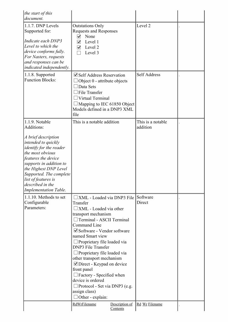
1.1.7. DNP Levels
Supported for:
Indicate each DNP3
Level to which the
device conforms fully.
For Nasters, requests
and responses can be
indicated independently.
Outstations Only
Requests and Responses None Level 1 Level 2
Level 3
Level 2 .
1.1.8. Supported
Function Blocks:
Self Address Reservation
Object 0 - attribute objects
Data Sets
File Transfer
Virtual Terminal
Mapping to IEC 61850 Object
Models defined in a DNP3 XML
file
Self Address .
1.1.9. Notable
Additions:
A brief description
intended to quickly
identify for the reader
the most obvious
features the device
supports in addition to
the Highest DNP Level
Supported. The complete
list of features is
described in the
Implementation Table.
This is a notable addition This is a notable
addition
.
1.1.10. Methods to set
Configurable
Parameters:
XML - Loaded via DNP3 File
Transfer
XML - Loaded via other
transport mechanism
Terminal - ASCII Terminal
Command Line Software - Vendor software
named Smart view
Proprietary file loaded via
DNP3 File Transfer
Proprietary file loaded via
other transport mechanism Direct - Keypad on device
front panel
Factory - Specified when
device is ordered
Protocol - Set via DNP3 (e.g.
assign class)
Other - explain:
Software
Direct
.
RdWrFilename Description of
Contents
Rd Wr Filename .
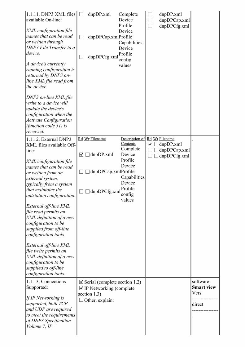
1.1.11. DNP3 XML files
available On-line:
XML configuration file
names that can be read
or written through
DNP3 File Transfer to a
device.
A device's currently
running configuration is
returned by DNP3 on-
line XML file read from
the device.
DNP3 on-line XML file
write to a device will
update the device's
configuration when the
Activate Configuration
(function code 31) is
received.
dnpDP.xml Complete
Device
Profile
dnpDPCap.xml
Device
Profile
Capabilities
dnpDPCfg.xml
Device
Profile
config
values
dnpDP.xml
dnpDPCap.xml
dnpDPCfg.xml
1.1.12. External DNP3
XML files available Off-
line:
XML configuration file
names that can be read
or written from an
external system,
typically from a system
that maintains the
outstation configuration.
External off-line XML
file read permits an
XML definition of a new
configuration to be
supplied from off-line
configuration tools.
External off-line XML
file write permits an
XML definition of a new
configuration to be
supplied to off-line
configuration tools.
Rd Wr Filename Description of
Contents
dnpDP.xml
Complete
Device
Profile
dnpDPCap.xml
Device
Profile
Capabilities
dnpDPCfg.xml
Device
Profile
config
values
Rd Wr Filename
dnpDP.xml
dnpDPCap.xml
dnpDPCfg.xml
.
1.1.13. Connections
Supported:
If IP Networking is
supported, both TCP
and UDP are required
to meet the requirements
of DNP3 Specification
Volume 7, IP
Serial (complete section 1.2) IP Networking (complete
section 1.3)
Other, explain:
software
Smart view
Vers
----------------
direct
----------------
.
Networking
Specification.
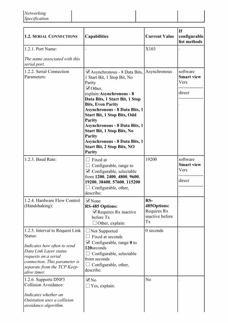
1.2. SERIAL CONNECTIONS Capabilities Current Value
If
configurable
list methods
1.2.1. Port Name:
The name associated with this
serial port.
- X103 -
1.2.2. Serial Connection
Parameters:
Asynchronous - 8 Data Bits,
1 Start Bit, 1 Stop Bit, No
Parity Other,
explain:Asynchronous - 8
Data Bits, 1 Start Bit, 1 Stop
Bits, Even Parity
Asynchronous - 8 Data Bits, 1
Start Bit, 1 Stop Bits, Odd
Parity
Asynchronous - 8 Data Bits, 1
Start Bit, 1 Stop Bits, No
Parity
Asynchronous - 8 Data Bits, 1
Start Bit, 2 Stop Bits, NO
Parity
Asynchronous software
Smart view
Vers
----------------
direct
----------------
.
1.2.3. Baud Rate: Fixed at
Configurable, range to Configurable, selectable
from 1200, 2400, 4800, 9600,
19200, 38400, 57600, 115200
Configurable, other,
describe:
19200 software
Smart view
Vers
----------------
direct
----------------
.
1.2.4. Hardware Flow Control
(Handshaking):
None
RS-485 Options: Requires Rx inactive
before Tx
Other, explain:
RS-
485Options:
Requires Rx
inactive before
Tx
.
1.2.5. Interval to Request Link
Status:
Indicates how often to send
Data Link Layer status
requests on a serial
connection. This parameter is
separate from the TCP Keep-
alive timer.
Not Supported
Fixed at seconds Configurable, range 0 to
120seconds
Configurable, selectable
from seconds
Configurable, other,
describe:
0 seconds .
1.2.6. Supports DNP3
Collision Avoidance:
Indicates whether an
Outstation uses a collision
avoidance algorithm.
No
Yes, explain:
No .
Documentation provided by the
vendor will provide
information on collision
avoidance schemes.
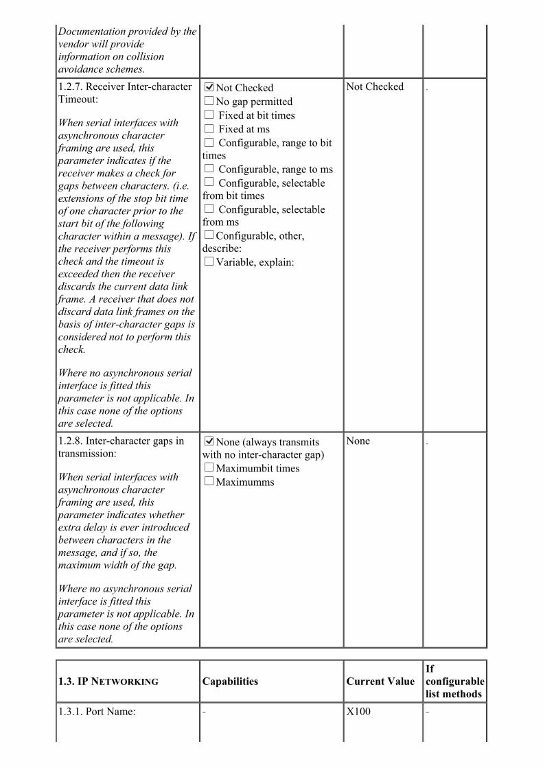
1.2.7. Receiver Inter-character
Timeout:
When serial interfaces with
asynchronous character
framing are used, this
parameter indicates if the
receiver makes a check for
gaps between characters. (i.e.
extensions of the stop bit time
of one character prior to the
start bit of the following
character within a message). If
the receiver performs this
check and the timeout is
exceeded then the receiver
discards the current data link
frame. A receiver that does not
discard data link frames on the
basis of inter-character gaps is
considered not to perform this
check.
Where no asynchronous serial
interface is fitted this
parameter is not applicable. In
this case none of the options
are selected.
Not Checked
No gap permitted
Fixed at bit times
Fixed at ms
Configurable, range to bit
times
Configurable, range to ms
Configurable, selectable
from bit times
Configurable, selectable
from ms
Configurable, other,
describe:
Variable, explain:
Not Checked .
1.2.8. Inter-character gaps in
transmission:
When serial interfaces with
asynchronous character
framing are used, this
parameter indicates whether
extra delay is ever introduced
between characters in the
message, and if so, the
maximum width of the gap.
Where no asynchronous serial
interface is fitted this
parameter is not applicable. In
this case none of the options
are selected.
None (always transmits
with no inter-character gap)
Maximumbit times
Maximumms
None .
1.3. IP NETWORKING Capabilities Current Value
If
configurable
list methods
1.3.1. Port Name: - X100 -

The name associated with this
network port.
1.3.2. Type of End Point: TCP Initiating (Master
Only) TCP Listening (Outstation
Only)
TCP Dual (required for
Masters) UDP Datagram (required)
software
Smart view
Vers
----------------
direct
----------------
.
1.3.3. IP Address of this
Device:
- see Device Para
TCP/IP IP
address
software
Smart view
Vers
----------------
direct
----------------
.
1.3.4. Subnet Mask: - see Device Para
TCP/IP Default
gateway
software
Smart view
Vers
----------------
direct
----------------
.
1.3.5. Gateway IP Address: - see Device Para
TCP/IP Default
gateway
software
Smart view
Vers
----------------
direct
----------------
.
1.3.6. Accepts TCP
Connections or UDP
Datagrams from:
Allows all (show as *.*.*.*
in 1.3.7)
Limits based on IP address
Limits based on list of IP
addresses
Limits based on a wildcard
IP address
Limits based on list of
wildcard IP addresses
Other validation, explain:
Allows all .
1.3.7. IP Address(es) from
which TCP Connections or
UDP Datagrams are accepted:
- *.*.*.* .
1.3.8. TCP Listen Port
Number:
If Outstation or dual end point
Mater, port number on which
to listen for incoming TCP
connect requests. Required to
be configureable for Masters
and recommended to be
configurable for Outstations.
Not Applicable (Master w/o
dual end point)
Fixed at 20,000
Configurable, range to Configurable, selectable
from 1 to 65535 Configurable, other,
describe: Not recommanded
to use ports in private area 0
20000 software
Smart view
Vers
----------------
direct
----------------
.

to 49152, and not possible to
use private ports 52151 to
52162.
1.3.9. TCP Listen Port Number
of remote device:
If Master or dual end point
Outstation, port number on
remote device with which to
initiate connection. Required to
be configurable for Masters
and recommended to be
configurable for Outstations.
Not Applicable (Outstation
w/o dual end point)
Fixed at 20,000
Configurable, range to
Configurable, selectable
from
Configurable, other,
describe:
Not Applicable .
1.3.10. TCP Keep-alive timer:
The time period for the keep-
alive timer on active TCP
connections.
Fixed at ms Configurable, range 1 to
7200ms
Configurable, selectable
from ms
Configurable, other,
describe:
720 ms software
Smart view
Vers
----------------
direct
----------------
.
1.3.11. Local UDP port:
Local UDP port for sending
and/or receiving UDP
datagrams. Masters may let
system choose an available
port. Outstations must use one
that is known by the Master.
Fixed at 20,000
Configurable, range to Configurable, selectable
from 1 to 65535 Configurable, other,
describe: Not recommanded
to use ports in private area 0
to 49152, and not possible to
use private ports 52151 to
52162.
Let system choose (Master
only)
20000 software
Smart view
Vers
----------------
direct
----------------
.
1.3.12. Destination UDP port
for DNP3 Requests (Master
Only):
- - .
1.3.13. Destination UDP port
for initial unsolicited null
responses (UDP only
Outstations):
For a UDP only Outstation,
the destination UDP port for
sending initial unsolicited Null
response.
None
Fixed at 20,000
Configurable, range to Configurable, selectable
from 1 to 65535 Configurable, other,
describe: Not recommanded
to use ports in private area 0
to 49152, and not possible to
use private ports 52151 to
52162.
same value as
Local UDP Port
(1.3.11)
software
Smart view
Vers
----------------
direct
----------------
.
1.3.14. Destination UDP port
for responses:
For a UDP only Outstation,
the destination UDP port for
sending all responses other
None
Fixed at 20,000
Configurable, range to Configurable, selectable
from 1 to 65535 Configurable, other,
same value as
Local UDP Port
(1.3.11)
software
Smart view
Vers
----------------
direct
than the initial unsolicited Null
response.
describe: Not recommanded
to use ports in private area 0
to 49152, and not possible to
use private ports 52151 to
52162.
Use source port number
----------------
.
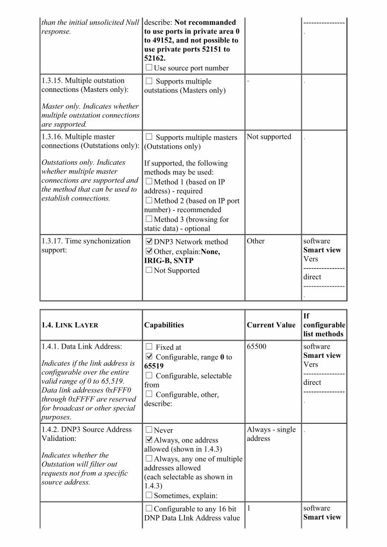
1.3.15. Multiple outstation
connections (Masters only):
Master only. Indicates whether
multiple outstation connections
are supported.
Supports multiple
outstations (Masters only)
- .
1.3.16. Multiple master
connections (Outstations only):
Outstations only. Indicates
whether multiple master
connections are supported and
the method that can be used to
establish connections.
Supports multiple masters
(Outstations only)
If supported, the following
methods may be used:
Method 1 (based on IP
address) - required
Method 2 (based on IP port
number) - recommended
Method 3 (browsing for
static data) - optional
Not supported .
1.3.17. Time synchonization
support:
DNP3 Network method Other, explain:None,
IRIG-B, SNTP
Not Supported
Other software
Smart view
Vers
----------------
direct
----------------
.
1.4. LINK LAYER Capabilities Current Value
If
configurable
list methods
1.4.1. Data Link Address:
Indicates if the link address is
configurable over the entire
valid range of 0 to 65,519.
Data link addresses 0xFFF0
through 0xFFFF are reserved
for broadcast or other special
purposes.
Fixed at Configurable, range 0 to
65519
Configurable, selectable
from
Configurable, other,
describe:
65500 software
Smart view
Vers
----------------
direct
----------------
.
1.4.2. DNP3 Source Address
Validation:
Indicates whether the
Outstation will filter out
requests not from a specific
source address.
Never Always, one address
allowed (shown in 1.4.3)
Always, any one of multiple
addresses allowed
(each selectable as shown in
1.4.3)
Sometimes, explain:
Always - single
address
.
Configurable to any 16 bit
DNP Data LInk Address value
1 software
Smart view
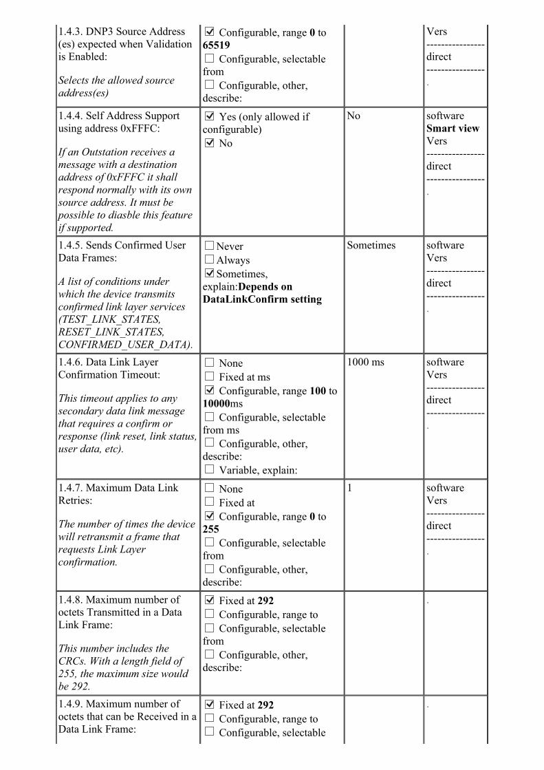
1.4.3. DNP3 Source Address
(es) expected when Validation
is Enabled:
Selects the allowed source
address(es)
Configurable, range 0 to
65519
Configurable, selectable
from
Configurable, other,
describe:
Vers
----------------
direct
----------------
.
1.4.4. Self Address Support
using address 0xFFFC:
If an Outstation receives a
message with a destination
address of 0xFFFC it shall
respond normally with its own
source address. It must be
possible to diasble this feature
if supported.
Yes (only allowed if
configurable) No
No software
Smart view
Vers
----------------
direct
----------------
.
1.4.5. Sends Confirmed User
Data Frames:
A list of conditions under
which the device transmits
confirmed link layer services
(TEST_LINK_STATES,
RESET_LINK_STATES,
CONFIRMED_USER_DATA).
Never
Always Sometimes,
explain:Depends on
DataLinkConfirm setting
Sometimes software
Vers
----------------
direct
----------------
.
1.4.6. Data Link Layer
Confirmation Timeout:
This timeout applies to any
secondary data link message
that requires a confirm or
response (link reset, link status,
user data, etc).
None
Fixed at ms Configurable, range 100 to
10000ms
Configurable, selectable
from ms
Configurable, other,
describe:
Variable, explain:
1000 ms software
Vers
----------------
direct
----------------
.
1.4.7. Maximum Data Link
Retries:
The number of times the device
will retransmit a frame that
requests Link Layer
confirmation.
None
Fixed at Configurable, range 0 to
255
Configurable, selectable
from
Configurable, other,
describe:
1 software
Vers
----------------
direct
----------------
.
1.4.8. Maximum number of
octets Transmitted in a Data
Link Frame:
This number includes the
CRCs. With a length field of
255, the maximum size would
be 292.
Fixed at 292
Configurable, range to
Configurable, selectable
from
Configurable, other,
describe:
.
1.4.9. Maximum number of
octets that can be Received in a
Data Link Frame:
Fixed at 292
Configurable, range to
Configurable, selectable
.
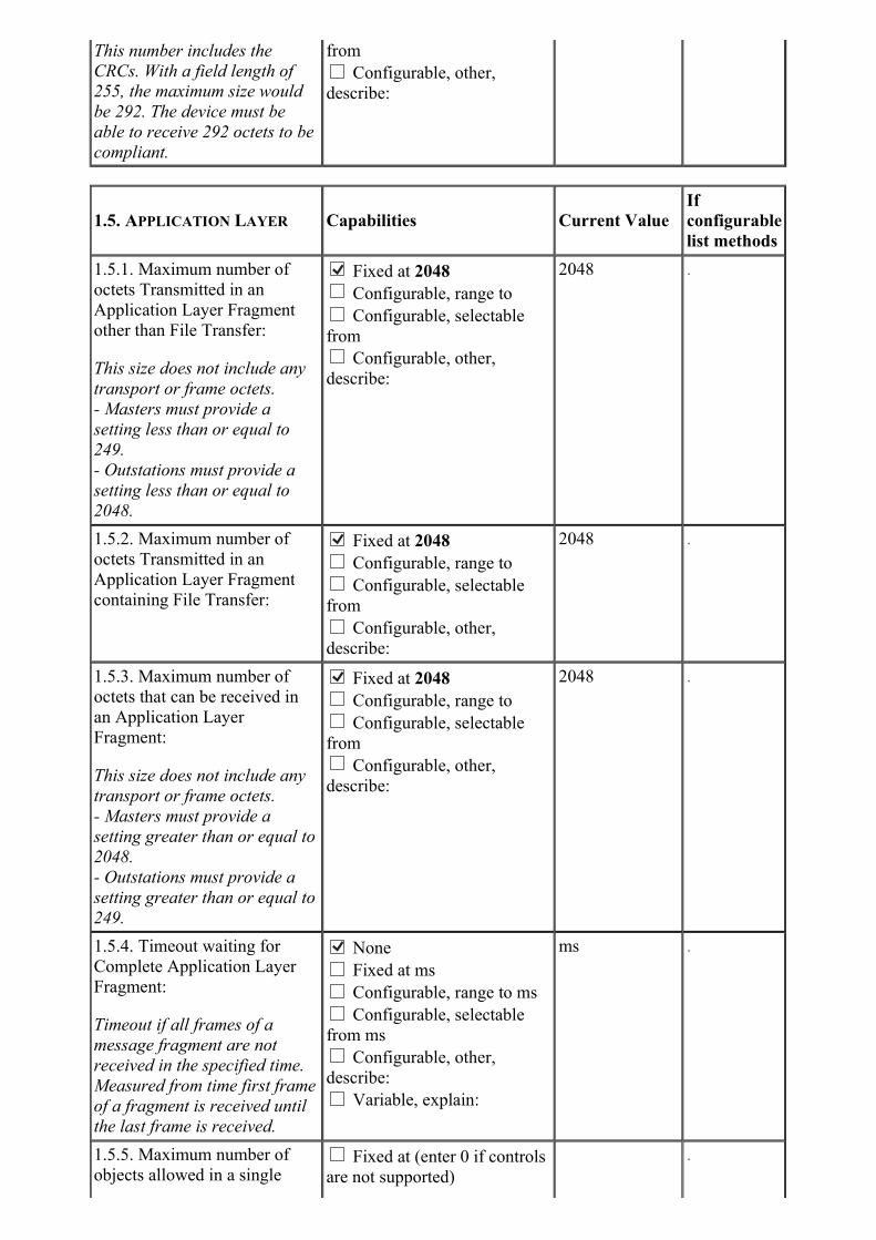
This number includes the
CRCs. With a field length of
255, the maximum size would
be 292. The device must be
able to receive 292 octets to be
compliant.
from
Configurable, other,
describe:
1.5. APPLICATION LAYER Capabilities Current Value
If
configurable
list methods
1.5.1. Maximum number of
octets Transmitted in an
Application Layer Fragment
other than File Transfer:
This size does not include any
transport or frame octets.
- Masters must provide a
setting less than or equal to
249.
- Outstations must provide a
setting less than or equal to
2048.
Fixed at 2048
Configurable, range to
Configurable, selectable
from
Configurable, other,
describe:
2048 .
1.5.2. Maximum number of
octets Transmitted in an
Application Layer Fragment
containing File Transfer:
Fixed at 2048
Configurable, range to
Configurable, selectable
from
Configurable, other,
describe:
2048 .
1.5.3. Maximum number of
octets that can be received in
an Application Layer
Fragment:
This size does not include any
transport or frame octets.
- Masters must provide a
setting greater than or equal to
2048.
- Outstations must provide a
setting greater than or equal to
249.
Fixed at 2048
Configurable, range to
Configurable, selectable
from
Configurable, other,
describe:
2048 .
1.5.4. Timeout waiting for
Complete Application Layer
Fragment:
Timeout if all frames of a
message fragment are not
received in the specified time.
Measured from time first frame
of a fragment is received until
the last frame is received.
None
Fixed at ms
Configurable, range to ms
Configurable, selectable
from ms
Configurable, other,
describe:
Variable, explain:
ms .
1.5.5. Maximum number of
objects allowed in a single Fixed at (enter 0 if controls
are not supported)
.
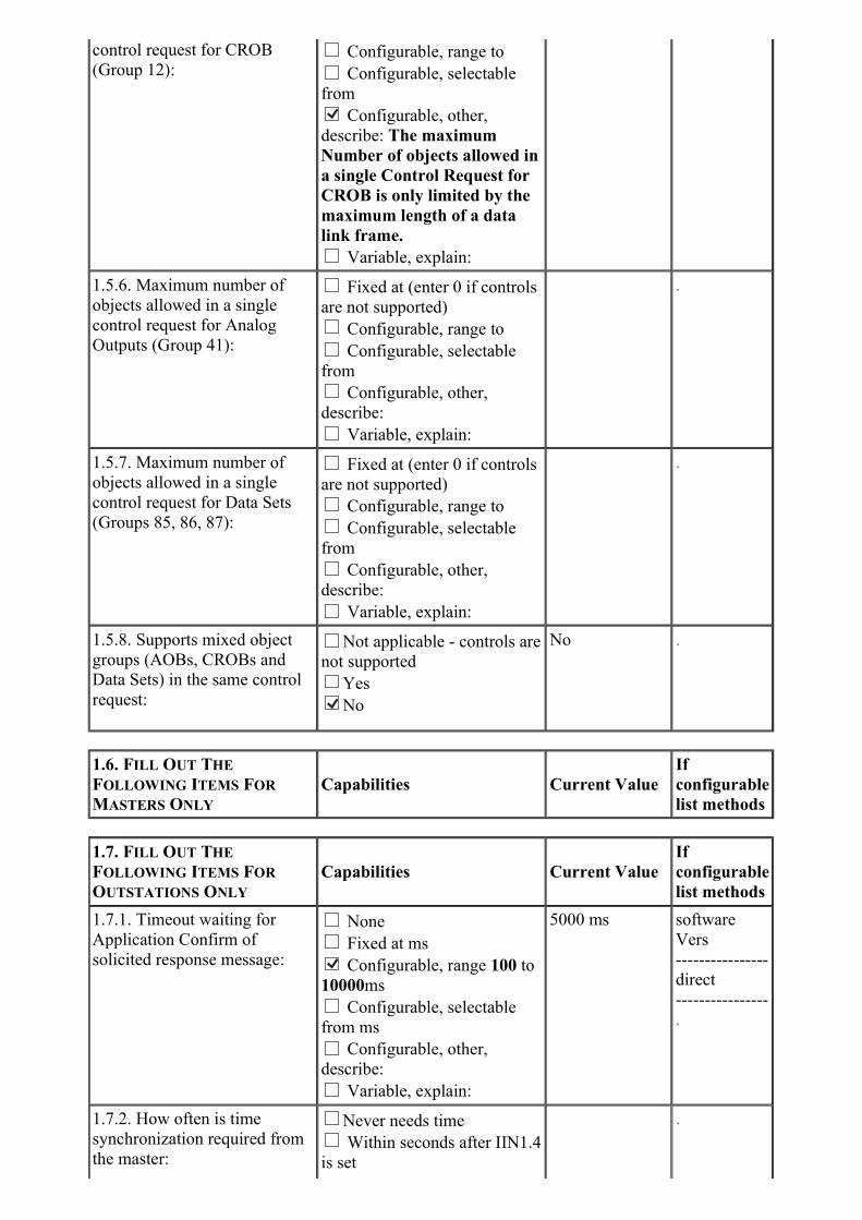
control request for CROB
(Group 12): Configurable, range to
Configurable, selectable
from Configurable, other,
describe: The maximum
Number of objects allowed in
a single Control Request for
CROB is only limited by the
maximum length of a data
link frame.
Variable, explain:
1.5.6. Maximum number of
objects allowed in a single
control request for Analog
Outputs (Group 41):
Fixed at (enter 0 if controls
are not supported)
Configurable, range to
Configurable, selectable
from
Configurable, other,
describe:
Variable, explain:
.
1.5.7. Maximum number of
objects allowed in a single
control request for Data Sets
(Groups 85, 86, 87):
Fixed at (enter 0 if controls
are not supported)
Configurable, range to
Configurable, selectable
from
Configurable, other,
describe:
Variable, explain:
.
1.5.8. Supports mixed object
groups (AOBs, CROBs and
Data Sets) in the same control
request:
Not applicable - controls are
not supported
Yes No
No .
1.6. FILL OUT THE
FOLLOWING ITEMS FOR
MASTERS ONLY
Capabilities Current Value
If
configurable
list methods
1.7. FILL OUT THE
FOLLOWING ITEMS FOR
OUTSTATIONS ONLY
Capabilities Current Value
If
configurable
list methods
1.7.1. Timeout waiting for
Application Confirm of
solicited response message:
None
Fixed at ms Configurable, range 100 to
10000ms
Configurable, selectable
from ms
Configurable, other,
describe:
Variable, explain:
5000 ms software
Vers
----------------
direct
----------------
.
1.7.2. How often is time
synchronization required from
the master:
Never needs time
Within seconds after IIN1.4
is set
.
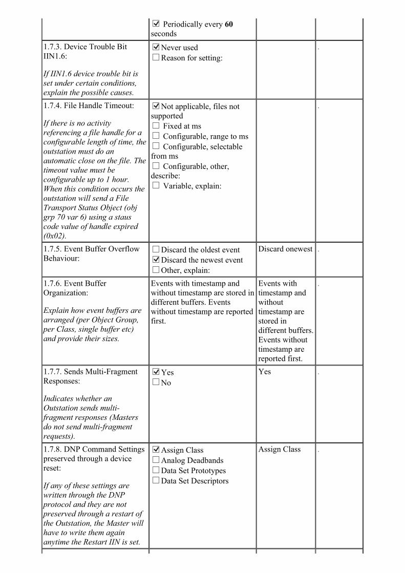
Periodically every 60
seconds
1.7.3. Device Trouble Bit
IIN1.6:
If IIN1.6 device trouble bit is
set under certain conditions,
explain the possible causes.
Never used
Reason for setting:
.
1.7.4. File Handle Timeout:
If there is no activity
referencing a file handle for a
configurable length of time, the
outstation must do an
automatic close on the file. The
timeout value must be
configurable up to 1 hour.
When this condition occurs the
outstation will send a File
Transport Status Object (obj
grp 70 var 6) using a staus
code value of handle expired
(0x02).
Not applicable, files not
supported
Fixed at ms
Configurable, range to ms
Configurable, selectable
from ms
Configurable, other,
describe:
Variable, explain:
.
1.7.5. Event Buffer Overflow
Behaviour:Discard the oldest event
Discard the newest event
Other, explain:
Discard onewest .
1.7.6. Event Buffer
Organization:
Explain how event buffers are
arranged (per Object Group,
per Class, single buffer etc)
and provide their sizes.
Events with timestamp and
without timestamp are stored in
different buffers. Events
without timestamp are reported
first.
Events with
timestamp and
without
timestamp are
stored in
different buffers.
Events without
timestamp are
reported first.
.
1.7.7. Sends Multi-Fragment
Responses:
Indicates whether an
Outstation sends multi-
fragment responses (Masters
do not send multi-fragment
requests).
Yes
No
Yes .
1.7.8. DNP Command Settings
preserved through a device
reset:
If any of these settings are
written through the DNP
protocol and they are not
preserved through a restart of
the Outstation, the Master will
have to write them again
anytime the Restart IIN is set.
Assign Class
Analog Deadbands
Data Set Prototypes
Data Set Descriptors
Assign Class .
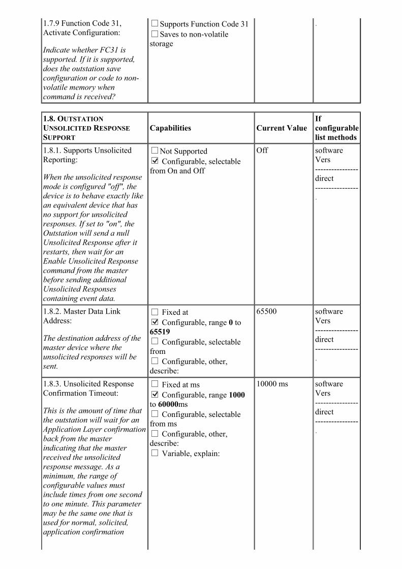
1.7.9 Function Code 31,
Activate Configuration:
Indicate whether FC31 is
supported. If it is supported,
does the outstation save
configuration or code to non-
volatile memory when
command is received?
Supports Function Code 31
Saves to non-volatile
storage
.
1.8. OUTSTATION
UNSOLICITED RESPONSE
SUPPORT
Capabilities Current Value
If
configurable
list methods
1.8.1. Supports Unsolicited
Reporting:
When the unsolicited response
mode is configured "off", the
device is to behave exactly like
an equivalent device that has
no support for unsolicited
responses. If set to "on", the
Outstation will send a null
Unsolicited Response after it
restarts, then wait for an
Enable Unsolicited Response
command from the master
before sending additional
Unsolicited Responses
containing event data.
Not Supported Configurable, selectable
from On and Off
Off software
Vers
----------------
direct
----------------
.
1.8.2. Master Data Link
Address:
The destination address of the
master device where the
unsolicited responses will be
sent.
Fixed at Configurable, range 0 to
65519
Configurable, selectable
from
Configurable, other,
describe:
65500 software
Vers
----------------
direct
----------------
.
1.8.3. Unsolicited Response
Confirmation Timeout:
This is the amount of time that
the outstation will wait for an
Application Layer confirmation
back from the master
indicating that the master
received the unsolicited
response message. As a
minimum, the range of
configurable values must
include times from one second
to one minute. This parameter
may be the same one that is
used for normal, solicited,
application confirmation
Fixed at ms Configurable, range 1000
to 60000ms
Configurable, selectable
from ms
Configurable, other,
describe:
Variable, explain:
10000 ms software
Vers
----------------
direct
----------------
.
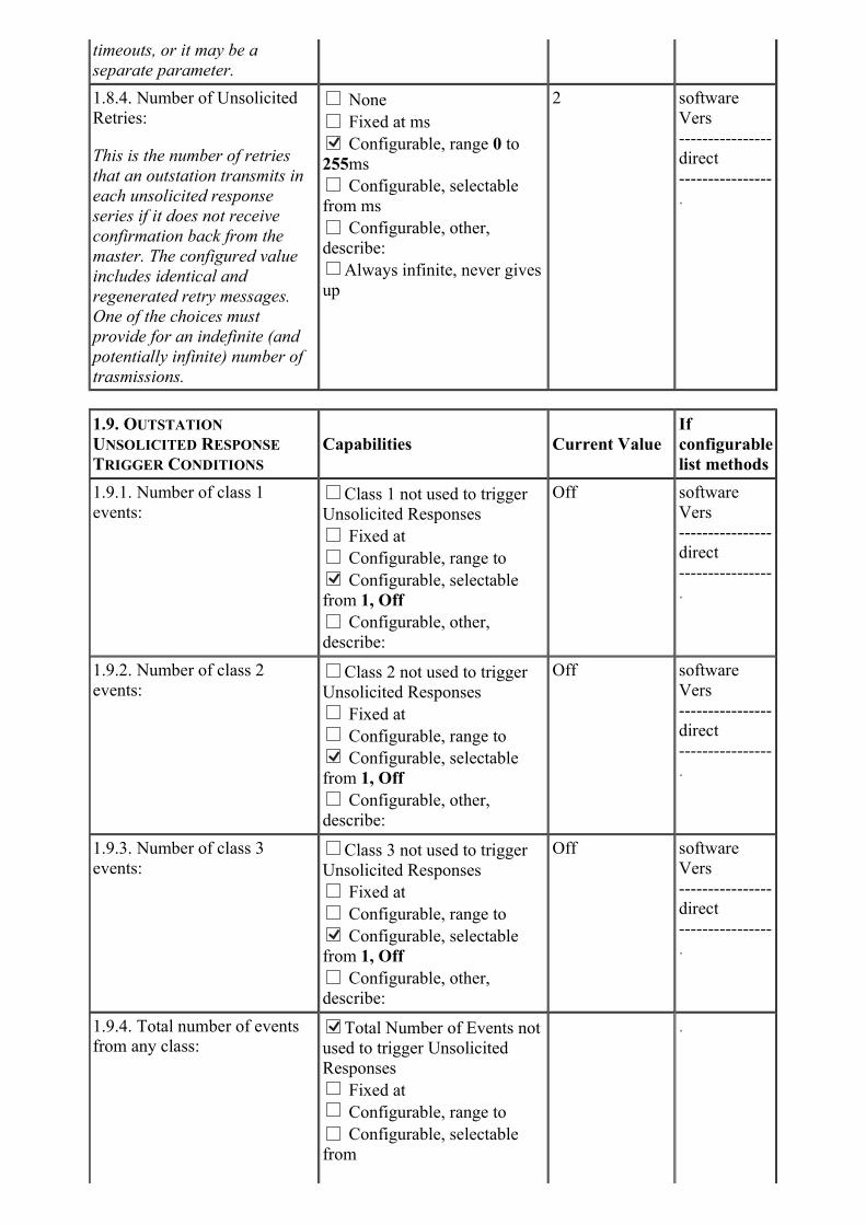
timeouts, or it may be a
separate parameter.
1.8.4. Number of Unsolicited
Retries:
This is the number of retries
that an outstation transmits in
each unsolicited response
series if it does not receive
confirmation back from the
master. The configured value
includes identical and
regenerated retry messages.
One of the choices must
provide for an indefinite (and
potentially infinite) number of
trasmissions.
None
Fixed at ms Configurable, range 0 to
255ms
Configurable, selectable
from ms
Configurable, other,
describe:
Always infinite, never gives
up
2 software
Vers
----------------
direct
----------------
.
1.9. OUTSTATION
UNSOLICITED RESPONSE
TRIGGER CONDITIONS
Capabilities Current Value
If
configurable
list methods
1.9.1. Number of class 1
events:Class 1 not used to trigger
Unsolicited Responses
Fixed at
Configurable, range to Configurable, selectable
from 1, Off
Configurable, other,
describe:
Off software
Vers
----------------
direct
----------------
.
1.9.2. Number of class 2
events:Class 2 not used to trigger
Unsolicited Responses
Fixed at
Configurable, range to Configurable, selectable
from 1, Off
Configurable, other,
describe:
Off software
Vers
----------------
direct
----------------
.
1.9.3. Number of class 3
events:Class 3 not used to trigger
Unsolicited Responses
Fixed at
Configurable, range to Configurable, selectable
from 1, Off
Configurable, other,
describe:
Off software
Vers
----------------
direct
----------------
.
1.9.4. Total number of events
from any class:
Total Number of Events not
used to trigger Unsolicited
Responses
Fixed at
Configurable, range to
Configurable, selectable
from
.

Configurable, other,
describe:
1.9.5. Hold time after class 1
event:
A configurable value of 0
indicates that responses are
not delayed due to this
parameter.
Class 1 not used to trigger
Unsolicited Responses Fixed at ms
Configurable, range to ms
Configurable, selectable
from ms
Configurable, other,
describe:
0 ms .
1.9.6. Hold time after class 2
event:
A configurable value of 0
indicates that responses are
not delayed due to this
parameter.
Class 2 not used to trigger
Unsolicited Responses Fixed at ms
Configurable, range to ms
Configurable, selectable
from ms
Configurable, other,
describe:
0 ms .
1.9.7. Hold time after class 3
event:
A configurable value of 0
indicates that responses are
not delayed due to this
parameter.
Class 3 not used to trigger
Unsolicited Responses Fixed at ms
Configurable, range to ms
Configurable, selectable
from ms
Configurable, other,
describe:
0 ms .
1.9.8. Hold time after event
assigned to any class:
A configurable value of 0
indicates that responses are
not delayed due to this
parameter.
Class events not used to
trigger Unsolicited Responses Fixed at ms
Configurable, range to ms
Configurable, selectable
from ms
Configurable, other,
describe:
0 ms .
1.9.9. Retrigger Hold Time:
The hold-time timer may be
retriggered for each new event
detected (increased possibility
of capturing all the changes in
a single response) or not
retriggered (giving the master
a guaranteed update time).
Hold-time timer will be
retriggered for each new event
detected (may get more
changes in next response) Hold-time timer will not be
retriggered for each new event
detected (guaranteed update
time)
Not retriggered .
1.9.10. Other Unsolicited
Response Trigger Conditions:
.
1.10. OUTSTATION
PERFORMANCECapabilities Current Value
If
configurable
list methods
- 1 ms -

1.10.1. Maximum Time Base
Drift (milliseconds per
minute):
If the device is synchronized by
DNP, what is the clock drift
rate over the full operating
temperature range.
1.10.2. When does outstation
set IIN1.4?
Never Asserted at startup until first
Time Synchronization request
received Periodically, range 60s to
60s seconds
Periodically, selectable
from seconds
Range to seconds after last
time sync
Selectable from seconds
after last time sync
When time error may have
drifted by range to ms
When time error may have
drifted by selectable from ms
Never .
1.10.3. Maximum Internal
Time Reference Error when set
via DNP (ms):
The difference between the
time set in DNP Write Time
message, and the time actually
set in the outstation.
- 1 ms -
1.10.4. Maximum Delay
Measurement Error (ms):
The difference between the
time reported in the delay
measurement response and the
actual time between receipt of
the delay measurement request
and issuing the delay
measurement reply.
- 1 ms -
1.10.5. Maximum Response
Time (ms):
The amount of time an
outstation will take to respond
upon receipt of a valid request.
This does not include the
message transmission time.
- 50 ms -
1.10.6. Maximum time from
start-up to IIN 1.4 assertion
(ms):
- 15 ms -
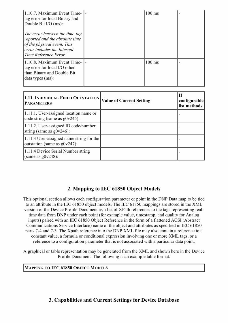
1.10.7. Maximum Event Time-
tag error for local Binary and
Double Bit I/O (ms):
The error between the time-tag
reported and the absolute time
of the physical event. This
error includes the Internal
Time Reference Error.
- 100 ms -
1.10.8. Maximum Event Time-
tag error for local I/O other
than Binary and Double Bit
data types (ms):
- 100 ms -
1.11. INDIVIDUAL FIELD OUTSTATION
PARAMETERSValue of Current Setting
If
configurable
list methods
1.11.1. User-assigned location name or
code string (same as g0v245):
.
1.11.2. User-assigned ID code/number
string (same as g0v246):
.
1.11.3 User-assigned name string for the
outstation (same as g0v247):
.
1.11.4 Device Serial Number string
(same as g0v248):
.
2. Mapping to IEC 61850 Object Models
This optional section allows each configuration parameter or point in the DNP Data map to be tied
to an attribute in the IEC 61850 object models. The IEC 61850 mappings are stored in the XML
version of the Device Profile Document as a list of XPath references to the tags representing real-
time data from DNP under each point (for example value, timestamp, and quality for Analog
inputs) paired with an IEC 61850 Object Reference in the form of a flattened ACSI (Abstract
Communications Service Interface) name of the object and attributes as specified in IEC 61850
parts 7-4 and 7-3. The Xpath reference into the DNP XML file may also contain a reference to a
constant value, a formula or conditional expression involving one or more XML tags, or a
reference to a configuration parameter that is not associated with a particular data point.
A graphical or table representation may be generated from the XML and shown here in the Device
Profile Document. The following is an example table format.
MAPPING TO IEC 61850 OBJECT MODELS
3. Capabilities and Current Settings for Device Database
The following tables identify the capabilities and current settings for each DNP3 data type. Each
data type also provides a table defining the data points available in the device or a description of
how this information can be obtained if the database is configurable.
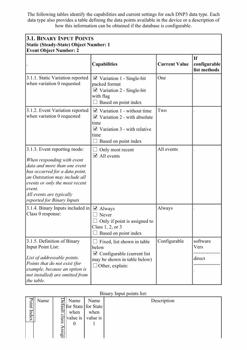
3.1. BINARY INPUT POINTS
Static (Steady-State) Object Number: 1
Event Object Number: 2
. Capabilities Current Value
If
configurable
list methods
3.1.1. Static Variation reported
when variation 0 requested
Variation 1 - Single-bit
packed format Variation 2 - Single-bit
with flag
Based on point index
One .
3.1.2. Event Variation reported
when variation 0 requested
Variation 1 - without time Variation 2 - with absolute
time Variation 3 - with relative
time
Based on point index
Two .
3.1.3. Event reporting mode:
When responding with event
data and more than one event
has occurred for a data point,
an Outstation may include all
events or only the most recent
event.
All events are typically
reported for Binary Inputs
Only most recent All events
All events .
3.1.4. Binary Inputs included in
Class 0 response:
Always
Never
Only if point is assigned to
Class 1, 2, or 3
Based on point index
Always .
3.1.5. Definition of Binary
Input Point List:
List of addressable points.
Points that do not exist (for
example, because an option is
not installed) are omitted from
the table.
Fixed, list shown in table
below Configurable (current list
may be shown in table below)
Other, explain:
Configurable software
Vers
----------------
direct
----------------
.
Binary Input points list:
Name Name
for State
when
value is
0
Name
for State
when
value is
1
Description

0
Binary
Input
Point 0
one
Depends
on the
selected
status
bit
Depends
on the
selected
status
bit
User configurable binary Input (select value from a list of
status bits)
...
63
Binary
Input
Point 63
one
Depends
on the
selected
status
bit
Depends
on the
selected
status
bit
User configurable binary Input (select value from a list of
status bits)
3.2. DOUBLE-BIT INPUT POINTS
Static (Steady-State) Object Number: 3
Event Object Number: 4
. Capabilities Current Value
If
configurable
list methods
3.2.1. Static Variation reported
when variation 0 requested
Variation 1 - Double-bit
packed format Variation 2 - Double-bit
with flag
Based on point index
One .
3.2.2. Event Variation reported
when variation 0 requested
Variation 1 - without time Variation 2 - with absolute
time Variation 3 - with relative
time
Based on point index
One .
3.2.3. Event reporting mode:
When responding with event
data and more than one event
has occurred for a data point,
an Outstation may include all
Only most recent All events
All events .
events or only the most recent
event.
All events are typically
reported for Double Bit Inputs
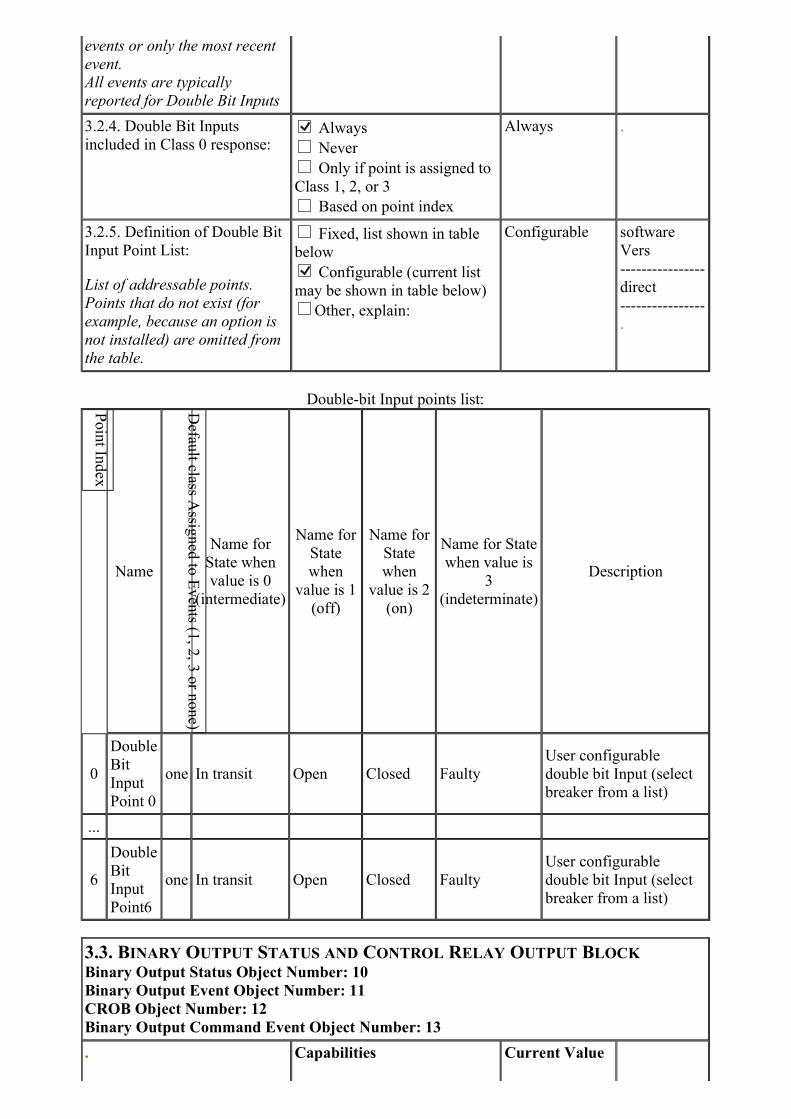
3.2.4. Double Bit Inputs
included in Class 0 response:
Always
Never
Only if point is assigned to
Class 1, 2, or 3
Based on point index
Always .
3.2.5. Definition of Double Bit
Input Point List:
List of addressable points.
Points that do not exist (for
example, because an option is
not installed) are omitted from
the table.
Fixed, list shown in table
below Configurable (current list
may be shown in table below)
Other, explain:
Configurable software
Vers
----------------
direct
----------------
.
Double-bit Input points list:
Name
Name for
State when
value is 0
(intermediate)
Name for
State
when
value is 1
(off)
Name for
State
when
value is 2
(on)
Name for State
when value is
3
(indeterminate)
Description
0
Double
Bit
Input
Point 0
one In transit Open Closed Faulty
User configurable
double bit Input (select
breaker from a list)
...
6
Double
Bit
Input
Point6
one In transit Open Closed Faulty
User configurable
double bit Input (select
breaker from a list)
3.3. BINARY OUTPUT STATUS AND CONTROL RELAY OUTPUT BLOCK
Binary Output Status Object Number: 10
Binary Output Event Object Number: 11
CROB Object Number: 12
Binary Output Command Event Object Number: 13
. Capabilities Current Value

If
configurable
list methods
3.3.1. Minimum pulse time
allowed with Trip, Close and
Pulse On commands.
Fixed at ms (hardware may
limit this further
Based on point index
.
3.3.2. Maximum pulse time
allowed with Trip, Close and
Pulse On commands.
Fixed at ms (hardware may
limit this further
Based on point index
.
3.3.3. Binary Output Status
included in Class 0 response:
Always
Never
Only if point is assigned to
Class 1, 2, or 3
Based on point index
Always .
3.3.4. Reports Output
Command Event Objects:
Never
Only upon a successful
Control
Upon all control attempts
Never .
3.3.5. Event Variation reported
when variation 0 requested
Variation 1 - without time Variation 2 - with absolute
time
Based on point index
One .
3.3.6. Command Event
Variation reported when
variation 0 requested
Variation 1 - without time
Variation 2 - with absolute
time
Based on point index
.
3.3.7. Change Event reporting
mode:
When responding with event
data and more than one event
has occurred for a data point,
an Outstation may include all
events or only the most recent
event.
Only most recent
All events
.
3.3.8. Command Event
reporting mode:
When responding with event
data and more than one event
has occurred for a data point,
an Outstation may include all
events or only the most recent
event.
Only most recent
All events
.
3.3.9. Maximum Time between
Select and Operate:Not Applicable
Fixed at seconds Configurable, range to
seconds
Configurable, selectable
from seconds
Configurable, other,
1 to 60 seconds .

describe:
Variable, explain:
Based on point index
3.3.10. Definition of Binary
Output Status / Control Relay
Output Block Points List:
List of addressable points.
Points that do not exist (for
example, because an option is
not installed) are omitted from
the table.
Fixed, list shown in table
below Configurable (current list
may be shown in table below)
Other, explain:
Configurable software
Vers
----------------
direct
----------------
.
Binary Output Status and CROB points list:
. Supported Control Operations . .
Name
Name
for
State
when
value is
0
Name
for
State
when
value
is 1
Description
0
Binary
Output
Point
0
Y Y Y Y - - - - - - inactive active none none
Single bit state
set by DNP
Binary Output
Point 0
... - - - - - - - - - -
31
Binary
Output
Point
31
Y Y Y Y - - - - - - inactive active none none
Single bit state
set by DNP
Binary Output
Point 31
3.4. COUNTERS / FROZEN COUNTERS
Static Counter Object Number: 20
Static Frozen Counter Object Number: 21
Counter Event Object Number: 22
Frozen Counter Event Object Number: 23

. Capabilities Current Value If
configurable
list methods
3.4.1. Static Counter Variation
reported when variation 0
requested
Variation 1 - 32-bit with
flag Variation 2 - 16-bit with
flag Variation 5 - 32-bit without
flag Variation 6 - 16-bit without
flag
Based on point index
One .
3.4.2. Counter Event Variation
reported when variation 0
requested
Variation 1 - 32-bit with
flag Variation 2 - 16-bit with
flag Variation 5 - 32-bit with
flag and time Variation 6 - 16-bit with
flag and time
Based on point index
One .
3.4.3. Counters included in
Class 0 response:
If counters are not included in
the Class 0 response, Counter
Events (group 22) may not be
reported.
Always
Never
Only if point is assigned to
Class 1, 2, or 3
Based on point index
Always .
3.4.4. Counter Event reporting
mode:
When responding with event
data and more than one event
has occurred for a data point,
an Outstation may include all
events or only the most recent
event.
All events are typically
reported for Counters
Only most recent
All events
Most recent .
3.4.5. Static Frozen Counter
Variation reported when
variation 0 requested:
Variation 1 - 32-bit with
flag
Variation 2 - 16-bit with
flag
Variation 5 - 32-bit with
flag and time
Variation 6 - 16-bit with
flag and time
Variation 9 - 32-bit without
flag
Variation 10 - 16-bit
without flag
Based on point index
.
.

3.4.6. Frozen Counter Event
Variation reported when
variation 0 requested:
Variation 1 - 32-bit with
flag
Variation 2 - 16-bit with
flag
Variation 5 - 32-bit without
flag
Variation 6 - 16-bit without
flag
Based on point index
3.4.7. Frozen Counters
included in Class 0 response: Always
Never
Only if point is assigned to
Class 1, 2, or 3
Based on point index
.
3.4.8. Frozen Counter Event
reporting mode:
When responding with event
data and more than one event
has occurred for a data point,
an Outstation may include all
events or only the most recent
event.
All events are typically
reported for Frozen ounters
Only most recent
All events
.
3.4.9. Counters Roll Over at: 16 Bits (65,535)
32 Bits (4,294,967,295)
Fixed at
Configurable, range to
Configurable, selectable
from Configurable, other,
describe: Based on selected
counter
Based on point index
Other .
3.4.10. Counters frozen by
means of:Master Request
Freezes itself without
concern for time of day
Freezes itself and requires
time of day
Other, explain:
.
3.4.11. Definition of Counter /
Frozen Counter Point List:
List of addressable points.
Points that do not exist (for
example, because an option is
not installed) are omitted from
the table.
Fixed, list shown in table
below Configurable (current list
may be shown in table below)
Other, explain:
Configurable software
Vers
----------------
direct
----------------
.
Counter / Frozen Counter points list:
Name Description

0
Binary
Counter
Point 0
three -User configurable binary cuonter (select value from a list
of counters)
... -
8
Binary
Counter
Point 8
three -User configurable binary cuonter (select value from a list
of counters)
3.5. ANALOG INPUT POINTS
Static (Steady-State) Object Number: 30
Event Object Number: 32
. Capabilities Current Value
If
configurable
list methods
3.5.1. Static Variation reported
when variation 0 requested
Variation 1 - 32-bit with
flag Variation 2 - 16-bit with
flag Variation 3 - 32-bit without
flag Variation 4 - 16-bit without
flag
Variation 5 - single-
precision floating point with
flag
Variation 6 - double-
precision floating point with
flag
Based on point index
One .
One .
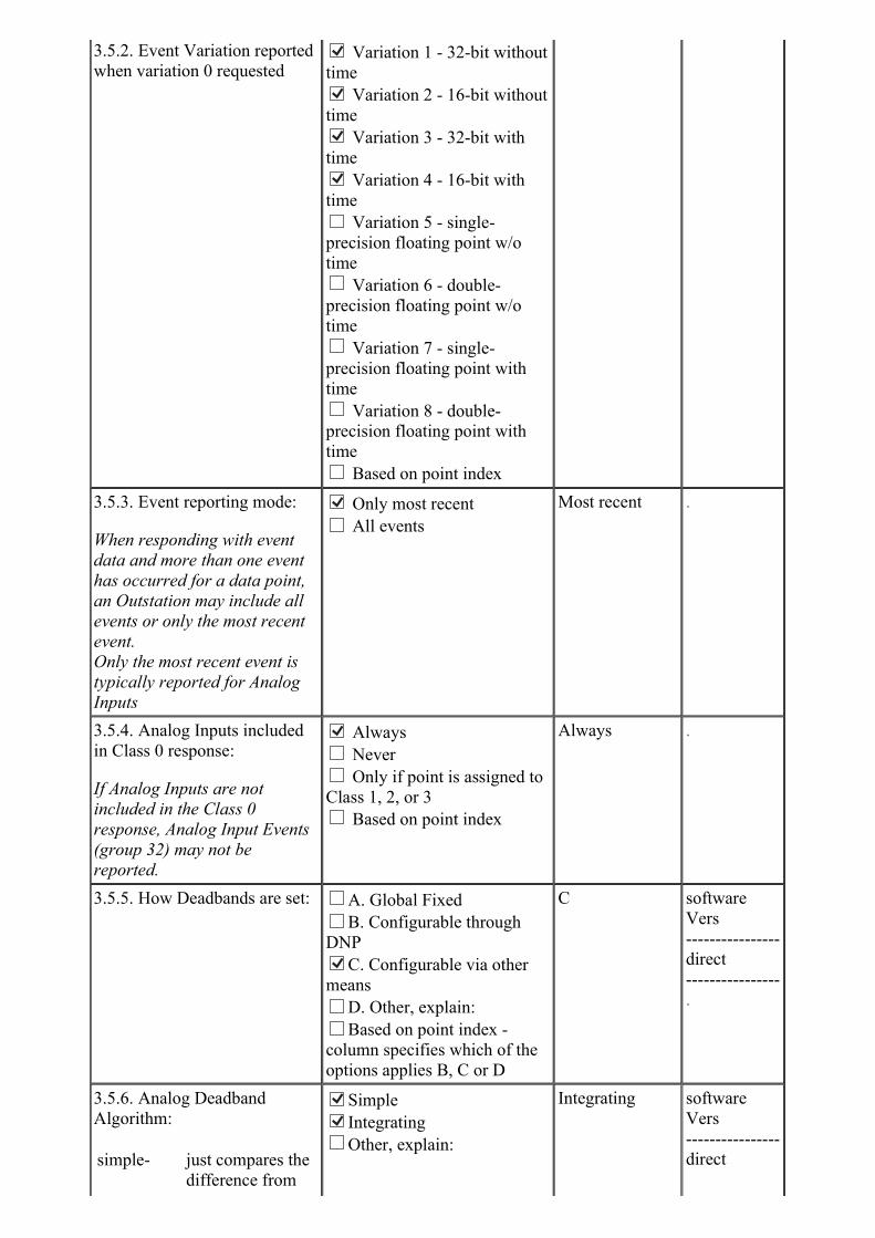
3.5.2. Event Variation reported
when variation 0 requested
Variation 1 - 32-bit without
time Variation 2 - 16-bit without
time Variation 3 - 32-bit with
time Variation 4 - 16-bit with
time
Variation 5 - single-
precision floating point w/o
time
Variation 6 - double-
precision floating point w/o
time
Variation 7 - single-
precision floating point with
time
Variation 8 - double-
precision floating point with
time
Based on point index
3.5.3. Event reporting mode:
When responding with event
data and more than one event
has occurred for a data point,
an Outstation may include all
events or only the most recent
event.
Only the most recent event is
typically reported for Analog
Inputs
Only most recent
All events
Most recent .
3.5.4. Analog Inputs included
in Class 0 response:
If Analog Inputs are not
included in the Class 0
response, Analog Input Events
(group 32) may not be
reported.
Always
Never
Only if point is assigned to
Class 1, 2, or 3
Based on point index
Always .
3.5.5. How Deadbands are set: A. Global Fixed
B. Configurable through
DNP C. Configurable via other
means
D. Other, explain:
Based on point index -
column specifies which of the
options applies B, C or D
C software
Vers
----------------
direct
----------------
.
3.5.6. Analog Deadband
Algorithm:
simple- just compares the
difference from
Simple Integrating
Other, explain:
Integrating software
Vers
----------------
direct
the previous
reported value
integrating- keeps track of the
accumulated
change
other- indicating another
algorithm
----------------
.
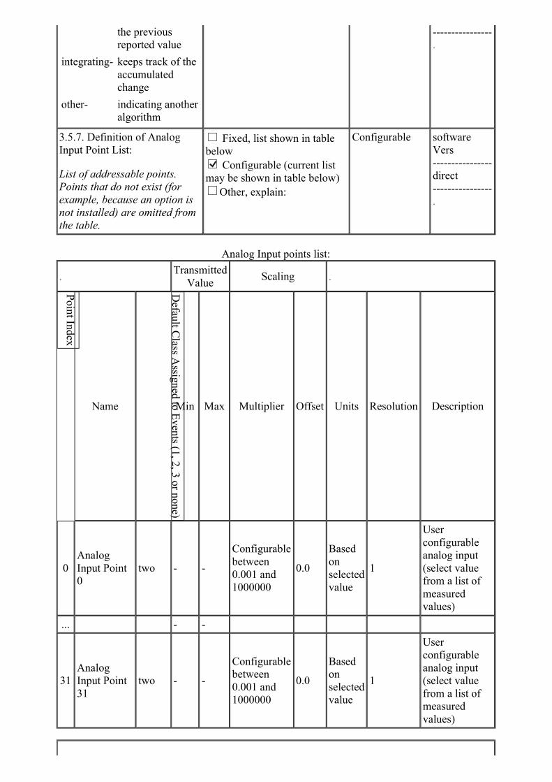
3.5.7. Definition of Analog
Input Point List:
List of addressable points.
Points that do not exist (for
example, because an option is
not installed) are omitted from
the table.
Fixed, list shown in table
below Configurable (current list
may be shown in table below)
Other, explain:
Configurable software
Vers
----------------
direct
----------------
.
Analog Input points list:
.Transmitted
ValueScaling .
Name Min Max Multiplier Offset Units Resolution Description
0
Analog
Input Point
0
two - -
Configurable
between
0.001 and
1000000
0.0
Based
on
selected
value
1
User
configurable
analog input
(select value
from a list of
measured
values)
... - -
31
Analog
Input Point
31
two - -
Configurable
between
0.001 and
1000000
0.0
Based
on
selected
value
1
User
configurable
analog input
(select value
from a list of
measured
values)
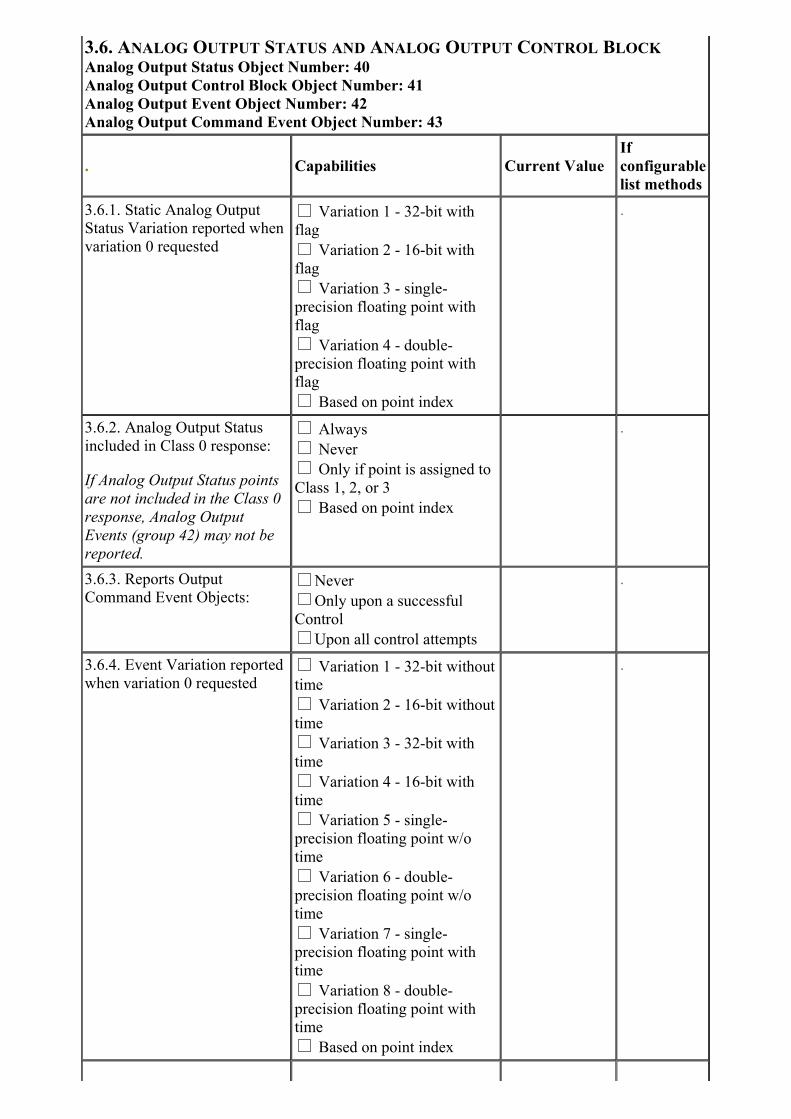
3.6. ANALOG OUTPUT STATUS AND ANALOG OUTPUT CONTROL BLOCK
Analog Output Status Object Number: 40
Analog Output Control Block Object Number: 41
Analog Output Event Object Number: 42
Analog Output Command Event Object Number: 43
. Capabilities Current Value
If
configurable
list methods
3.6.1. Static Analog Output
Status Variation reported when
variation 0 requested
Variation 1 - 32-bit with
flag
Variation 2 - 16-bit with
flag
Variation 3 - single-
precision floating point with
flag
Variation 4 - double-
precision floating point with
flag
Based on point index
.
3.6.2. Analog Output Status
included in Class 0 response:
If Analog Output Status points
are not included in the Class 0
response, Analog Output
Events (group 42) may not be
reported.
Always
Never
Only if point is assigned to
Class 1, 2, or 3
Based on point index
.
3.6.3. Reports Output
Command Event Objects:Never
Only upon a successful
Control
Upon all control attempts
.
3.6.4. Event Variation reported
when variation 0 requested Variation 1 - 32-bit without
time
Variation 2 - 16-bit without
time
Variation 3 - 32-bit with
time
Variation 4 - 16-bit with
time
Variation 5 - single-
precision floating point w/o
time
Variation 6 - double-
precision floating point w/o
time
Variation 7 - single-
precision floating point with
time
Variation 8 - double-
precision floating point with
time
Based on point index
.
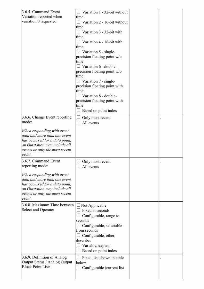
3.6.5. Command Event
Variation reported when
variation 0 requested
Variation 1 - 32-bit without
time
Variation 2 - 16-bit without
time
Variation 3 - 32-bit with
time
Variation 4 - 16-bit with
time
Variation 5 - single-
precision floating point w/o
time
Variation 6 - double-
precision floating point w/o
time
Variation 7 - single-
precision floating point with
time
Variation 8 - double-
precision floating point with
time
Based on point index
.
3.6.6. Change Event reporting
mode:
When responding with event
data and more than one event
has occurred for a data point,
an Outstation may include all
events or only the most recent
event.
Only most recent
All events
.
3.6.7. Command Event
reporting mode:
When responding with event
data and more than one event
has occurred for a data point,
an Outstation may include all
events or only the most recent
event.
Only most recent
All events
.
3.6.8. Maximum Time between
Select and Operate:Not Applicable
Fixed at seconds
Configurable, range to
seconds
Configurable, selectable
from seconds
Configurable, other,
describe:
Variable, explain:
Based on point index
.
3.6.9. Definition of Analog
Output Status / Analog Output
Block Point List:
Fixed, list shown in table
below
Configurable (current list
.
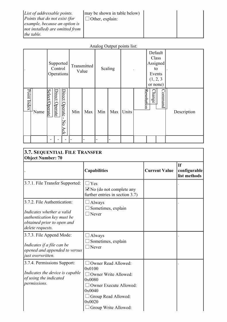
List of addressable points.
Points that do not exist (for
example, because an option is
not installed) are omitted from
the table.
may be shown in table below)
Other, explain:
Analog Output points list:
.
Supported
Control
Operations
Transmitted
ValueScaling .
Default
Class
Assigned
to
Events
(1, 2, 3
or none)
.
Name Min Max Min Max Units Description
- - - - - - -
3.7. SEQUENTIAL FILE TRANSFER
Object Number: 70
. Capabilities Current Value
If
configurable
list methods
3.7.1. File Transfer Supported: Yes No (do not complete any
further entries in section 3.7)
.
3.7.2. File Authentication:
Indicates whether a valid
authentication key must be
obtained prior to open and
delete requests.
Always
Sometimes, explain
Never
.
3.7.3. File Append Mode:
Indicates if a file can be
opened and appended to versus
just overwritten.
Always
Sometimes, explain
Never
.
3.7.4. Permissions Support:
Indicates the device is capable
of using the indicated
permissions.
Owner Read Allowed:
0x0100
Owner Write Allowed:
0x0080
Owner Execute Allowed:
0x0040
Group Read Allowed:
0x0020
Group Write Allowed:
.
0x0010
Group Execute Allowed:
0x0008
World Read Allowed:
0x0004
World Write Allowed:
0x0002
World Execute Allowed:
0x0001
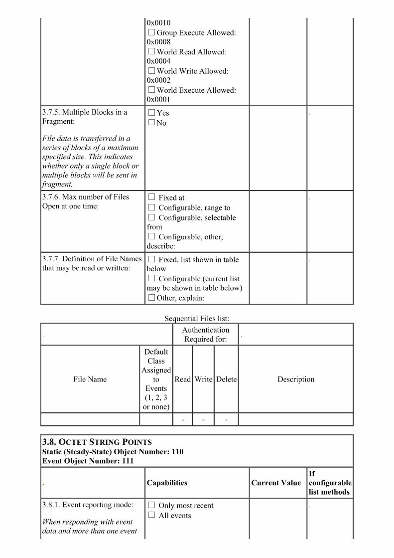
3.7.5. Multiple Blocks in a
Fragment:
File data is transferred in a
series of blocks of a maximum
specified size. This indicates
whether only a single block or
multiple blocks will be sent in
fragment.
Yes
No
.
3.7.6. Max number of Files
Open at one time: Fixed at
Configurable, range to
Configurable, selectable
from
Configurable, other,
describe:
.
3.7.7. Definition of File Names
that may be read or written: Fixed, list shown in table
below
Configurable (current list
may be shown in table below)
Other, explain:
.
Sequential Files list:
.Authentication
Required for:.
File Name
Default
Class
Assigned
to
Events
(1, 2, 3
or none)
Read Write Delete Description
- - -
3.8. OCTET STRING POINTS
Static (Steady-State) Object Number: 110
Event Object Number: 111
. Capabilities Current Value
If
configurable
list methods
3.8.1. Event reporting mode:
When responding with event
data and more than one event
Only most recent
All events
.
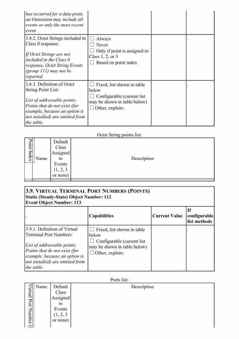
has occurred for a data point,
an Outstation may include all
events or only the most recent
event.
3.8.2. Octet Strings included in
Class 0 response:
If Octet Strings are not
included in the Class 0
response, Octet String Events
(group 111) may not be
reported.
Always
Never
Only if point is assigned to
Class 1, 2, or 3
Based on point index
.
3.8.3. Definition of Octet
String Point List:
List of addressable points.
Points that do not exist (for
example, because an option is
not installed) are omitted from
the table.
Fixed, list shown in table
below
Configurable (current list
may be shown in table below)
Other, explain:
.
Octet String points list:
Name
Default
Class
Assigned
to
Events
(1, 2, 3
or none)
Description
3.9. VIRTUAL TERMINAL PORT NUMBERS (POINTS)Static (Steady-State) Object Number: 112
Event Object Number: 113
. Capabilities Current Value
If
configurable
list methods
3.9.1. Definition of Virtual
Terminal Port Numbers:
List of addressable points.
Points that do not exist (for
example, because an option is
not installed) are omitted from
the table.
Fixed, list shown in table
below
Configurable (current list
may be shown in table below)
Other, explain:
.
Ports list:
Name Default
Class
Assigned
to
Events
(1, 2, 3
or none)
Description
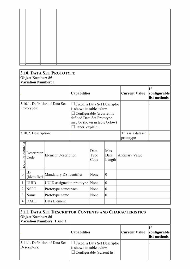
3.10. DATA SET PROTOTYPE
Object Number: 85
Variation Number: 1
. Capabilities Current Value
If
configurable
list methods
3.10.1. Definition of Data Set
Prototypes:Fixed, a Data Set Descriptor
is shown in table below
Configurable (a currently
defined Data Set Prototype
may be shown in table below)
Other, explain:
.
3.10.2. Description: . This is a dataset
prototype
.
Descriptor
CodeElement Description
Data
Type
Code
Max
Data
Length
Ancillary Value
0ID
(identifier)Mandatory DS identifier None 0
1 UUID UUID assigned to prototype None 0
2 NSPC Prototype namespace None 0
3 Name Prototype name None 0
4 DAEL Data Element
3.11. DATA SET DESCRIPTOR CONTENTS AND CHARACTERISTICS
Object Number: 86
Variation Numbers: 1 and 2
. Capabilities Current Value
If
configurable
list methods
3.11.1. Definition of Data Set
Descriptors:Fixed, a Data Set Descriptor
is shown in table below
Configurable (current list
.

may be shown in table below)
Other, explain:
3.11.2. Description: . .
3.11.3. Data Set Properties: Readable
Writable
Outstation maintains a static
data set
Outstation generates a data
set event
Data set defined by master
.
3.11.4. Default Event Assigned
Class:One
Two
Three
.
3.11.5. Static Data Set included
in Class 0 response: Always
Never
Only if point is assigned to
Class 1, 2, or 3
Based on point index
.
Descriptor
CodeElement Description
Data
Type
Code
Max
Data
Length
Ancillary Value
0ID
(identifier)Mandatory DS identifier None 0
Data set Points
DNP
Group
Number
Point Index
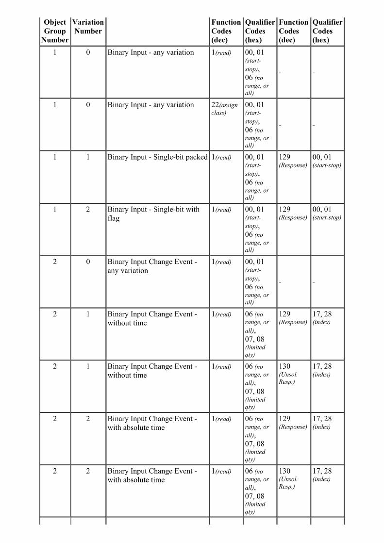
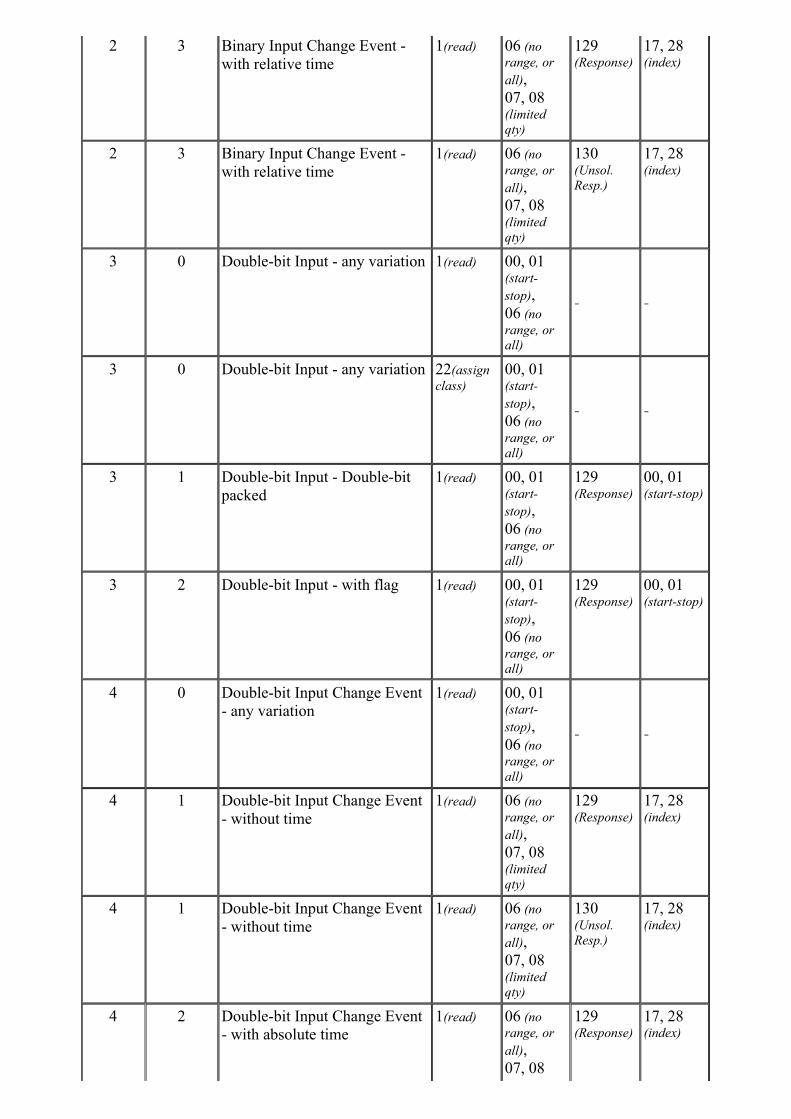
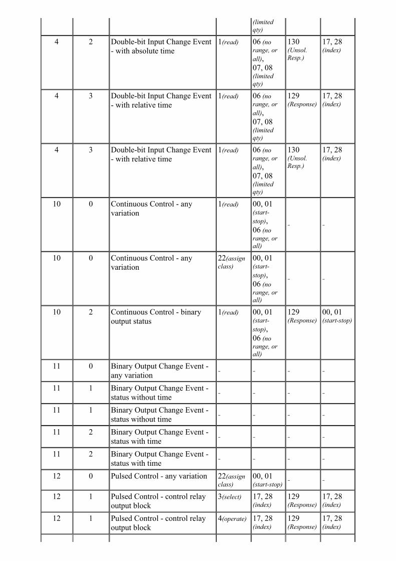
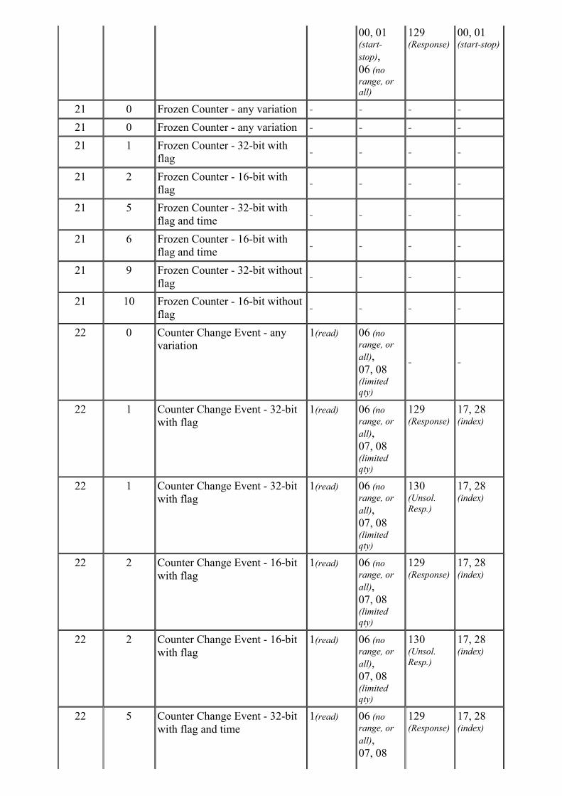
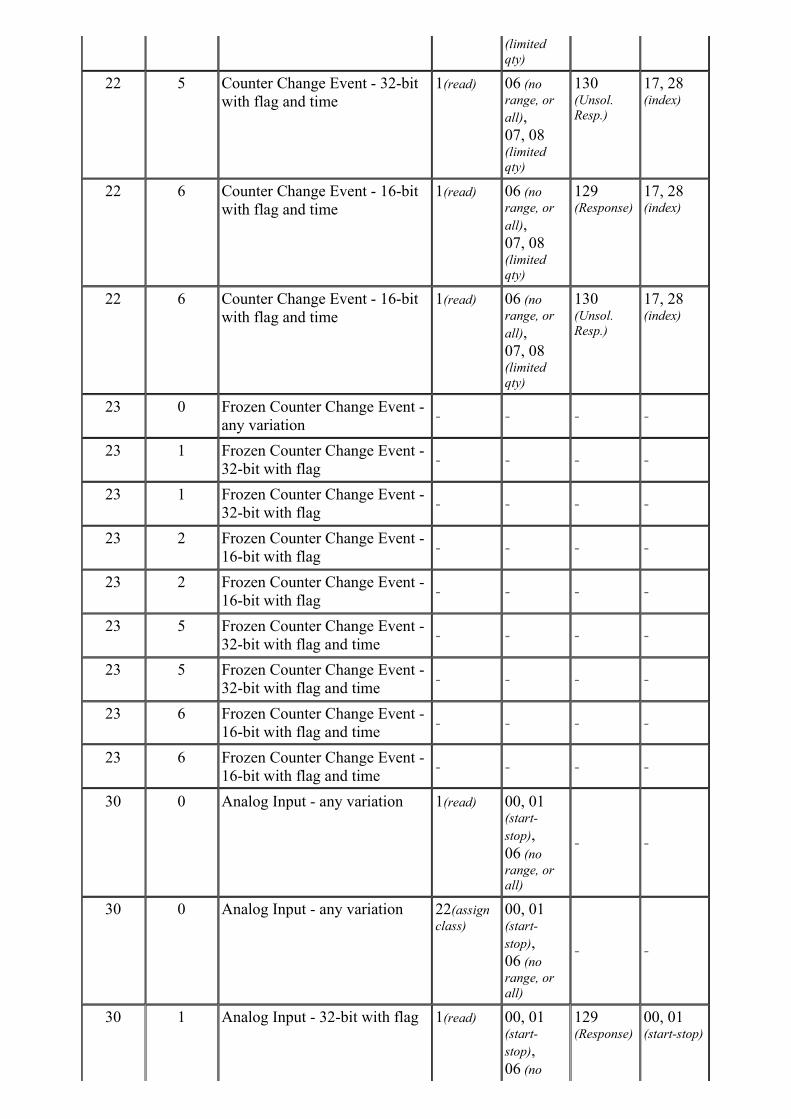
4. Implementation Table
The following implementation table identifies which object groups and variations, function codes
and qualifiers the device supports in both requests and responses. The Request columns identify
all requests that may be sent by a Master, or all requests that must be parsed by an Outstation. The
Response columns identify all responses that must be parsed by a Master, or all responses that
may be sent by an Outstation.
DNP OBJECT GROUP & VARIATION
REQUEST
Master may issue
Outstation must
parse
RESPONSE
Master must parse
Outstation may
issue
Description
Object
Group
Number
Variation
Number
Function
Codes
(dec)
Qualifier
Codes
(hex)
Function
Codes
(dec)
Qualifier
Codes
(hex)
1 0 Binary Input - any variation 1(read) 00, 01(start-
stop),
06 (no
range, or
all)
- -
1 0 Binary Input - any variation 22(assign
class)
00, 01(start-
stop),
06 (no
range, or
all)
- -
1 1 Binary Input - Single-bit packed 1(read) 00, 01(start-
stop),
06 (no
range, or
all)
129(Response)
00, 01(start-stop)
1 2 Binary Input - Single-bit with
flag
1(read) 00, 01(start-
stop),
06 (no
range, or
all)
129(Response)
00, 01(start-stop)
2 0 Binary Input Change Event -
any variation
1(read) 00, 01(start-
stop),
06 (no
range, or
all)
- -
2 1 Binary Input Change Event -
without time
1(read) 06 (no
range, or
all),
07, 08(limited
qty)
129(Response)
17, 28(index)
2 1 Binary Input Change Event -
without time
1(read) 06 (no
range, or
all),
07, 08(limited
qty)
130(Unsol.
Resp.)
17, 28(index)
2 2 Binary Input Change Event -
with absolute time
1(read) 06 (no
range, or
all),
07, 08(limited
qty)
129(Response)
17, 28(index)
2 2 Binary Input Change Event -
with absolute time
1(read) 06 (no
range, or
all),
07, 08(limited
qty)
130(Unsol.
Resp.)
17, 28(index)
2 3 Binary Input Change Event -
with relative time
1(read) 06 (no
range, or
all),
07, 08(limited
qty)
129(Response)
17, 28(index)
2 3 Binary Input Change Event -
with relative time
1(read) 06 (no
range, or
all),
07, 08(limited
qty)
130(Unsol.
Resp.)
17, 28(index)
3 0 Double-bit Input - any variation 1(read) 00, 01(start-
stop),
06 (no
range, or
all)
- -
3 0 Double-bit Input - any variation 22(assign
class)
00, 01(start-
stop),
06 (no
range, or
all)
- -
3 1 Double-bit Input - Double-bit
packed
1(read) 00, 01(start-
stop),
06 (no
range, or
all)
129(Response)
00, 01(start-stop)
3 2 Double-bit Input - with flag 1(read) 00, 01(start-
stop),
06 (no
range, or
all)
129(Response)
00, 01(start-stop)
4 0 Double-bit Input Change Event
- any variation
1(read) 00, 01(start-
stop),
06 (no
range, or
all)
- -
4 1 Double-bit Input Change Event
- without time
1(read) 06 (no
range, or
all),
07, 08(limited
qty)
129(Response)
17, 28(index)
4 1 Double-bit Input Change Event
- without time
1(read) 06 (no
range, or
all),
07, 08(limited
qty)
130(Unsol.
Resp.)
17, 28(index)
4 2 Double-bit Input Change Event
- with absolute time
1(read) 06 (no
range, or
all),
07, 08
129(Response)
17, 28(index)
(limited
qty)
4 2 Double-bit Input Change Event
- with absolute time
1(read) 06 (no
range, or
all),
07, 08(limited
qty)
130(Unsol.
Resp.)
17, 28(index)
4 3 Double-bit Input Change Event
- with relative time
1(read) 06 (no
range, or
all),
07, 08(limited
qty)
129(Response)
17, 28(index)
4 3 Double-bit Input Change Event
- with relative time
1(read) 06 (no
range, or
all),
07, 08(limited
qty)
130(Unsol.
Resp.)
17, 28(index)
10 0 Continuous Control - any
variation
1(read) 00, 01(start-
stop),
06 (no
range, or
all)
- -
10 0 Continuous Control - any
variation
22(assign
class)
00, 01(start-
stop),
06 (no
range, or
all)
- -
10 2 Continuous Control - binary
output status
1(read) 00, 01(start-
stop),
06 (no
range, or
all)
129(Response)
00, 01(start-stop)
11 0 Binary Output Change Event -
any variation- - - -
11 1 Binary Output Change Event -
status without time- - - -
11 1 Binary Output Change Event -
status without time- - - -
11 2 Binary Output Change Event -
status with time- - - -
11 2 Binary Output Change Event -
status with time- - - -
12 0 Pulsed Control - any variation 22(assign
class)
00, 01(start-stop)
- -
12 1 Pulsed Control - control relay
output block
3(select) 17, 28(index)
129(Response)
17, 28(index)
12 1 Pulsed Control - control relay
output block
4(operate) 17, 28(index)
129(Response)
17, 28(index)

12 1 Pulsed Control - control relay
output block
5(direct
op.)
17, 28(index)
129(Response)
17, 28(index)
12 1 Pulsed Control - control relay
output block
6(direct
op, no ack)
17, 28(index)
129(Response)
17, 28(index)
12 2 Pulsed Control - pattern control
block
5(direct
op.)
07 (limited
qty = 1)
129(Response)
07 (limited
qty = 1)
12 2 Pulsed Control - pattern control
block
6(direct
op, no ack)
07 (limited
qty = 1)
129(Response)
07 (limited
qty = 1)
12 3 Pulsed Control - pattern mask 5(direct
op.)
00, 01(start-stop)
129(Response)
00, 01(start-stop)
12 3 Pulsed Control - pattern mask 6(direct
op, no ack)
00, 01(start-stop)
129(Response)
00, 01(start-stop)
13 0 Binary Output Command Event
- any variation- - - -
13 1 Binary Output Command Event
- without time- - - -
13 1 Binary Output Command Event
- without time- - - -
13 2 Binary Output Command Event
- with time- - - -
13 2 Binary Output Command Event
- with time- - - -
20 0 Counter - any variation 1(read) 00, 01(start-
stop),
06 (no
range, or
all)
- -
20 0 Counter - any variation 22(assign
class)
00, 01(start-
stop),
06 (no
range, or
all)
- -
20 1 Counter - 32-bit with flag 1(read) 00, 01(start-
stop),
06 (no
range, or
all)
129(Response)
00, 01(start-stop)
20 2 Counter - 16-bit with flag 1(read) 00, 01(start-
stop),
06 (no
range, or
all)
129(Response)
00, 01(start-stop)
20 5 Counter - 32-bit without flag 1(read) 00, 01(start-
stop),
06 (no
range, or
all)
129(Response)
00, 01(start-stop)
20 6 Counter - 16-bit without flag 1(read)
00, 01(start-
stop),
06 (no
range, or
all)
129(Response)
00, 01(start-stop)
21 0 Frozen Counter - any variation - - - -
21 0 Frozen Counter - any variation - - - -
21 1 Frozen Counter - 32-bit with
flag- - - -
21 2 Frozen Counter - 16-bit with
flag- - - -
21 5 Frozen Counter - 32-bit with
flag and time- - - -
21 6 Frozen Counter - 16-bit with
flag and time- - - -
21 9 Frozen Counter - 32-bit without
flag- - - -
21 10 Frozen Counter - 16-bit without
flag- - - -
22 0 Counter Change Event - any
variation
1(read) 06 (no
range, or
all),
07, 08(limited
qty)
- -
22 1 Counter Change Event - 32-bit
with flag
1(read) 06 (no
range, or
all),
07, 08(limited
qty)
129(Response)
17, 28(index)
22 1 Counter Change Event - 32-bit
with flag
1(read) 06 (no
range, or
all),
07, 08(limited
qty)
130(Unsol.
Resp.)
17, 28(index)
22 2 Counter Change Event - 16-bit
with flag
1(read) 06 (no
range, or
all),
07, 08(limited
qty)
129(Response)
17, 28(index)
22 2 Counter Change Event - 16-bit
with flag
1(read) 06 (no
range, or
all),
07, 08(limited
qty)
130(Unsol.
Resp.)
17, 28(index)
22 5 Counter Change Event - 32-bit
with flag and time
1(read) 06 (no
range, or
all),
07, 08
129(Response)
17, 28(index)
(limited
qty)
22 5 Counter Change Event - 32-bit
with flag and time
1(read) 06 (no
range, or
all),
07, 08(limited
qty)
130(Unsol.
Resp.)
17, 28(index)
22 6 Counter Change Event - 16-bit
with flag and time
1(read) 06 (no
range, or
all),
07, 08(limited
qty)
129(Response)
17, 28(index)
22 6 Counter Change Event - 16-bit
with flag and time
1(read) 06 (no
range, or
all),
07, 08(limited
qty)
130(Unsol.
Resp.)
17, 28(index)
23 0 Frozen Counter Change Event -
any variation- - - -
23 1 Frozen Counter Change Event -
32-bit with flag- - - -
23 1 Frozen Counter Change Event -
32-bit with flag- - - -
23 2 Frozen Counter Change Event -
16-bit with flag- - - -
23 2 Frozen Counter Change Event -
16-bit with flag- - - -
23 5 Frozen Counter Change Event -
32-bit with flag and time- - - -
23 5 Frozen Counter Change Event -
32-bit with flag and time- - - -
23 6 Frozen Counter Change Event -
16-bit with flag and time- - - -
23 6 Frozen Counter Change Event -
16-bit with flag and time- - - -
30 0 Analog Input - any variation 1(read) 00, 01(start-
stop),
06 (no
range, or
all)
- -
30 0 Analog Input - any variation 22(assign
class)
00, 01(start-
stop),
06 (no
range, or
all)
- -
30 1 Analog Input - 32-bit with flag 1(read) 00, 01(start-
stop),
06 (no
129(Response)
00, 01(start-stop)

range, or
all)
30 2 Analog Input - 16-bit with flag 1(read) 00, 01(start-
stop),
06 (no
range, or
all)
129(Response)
00, 01(start-stop)
30 3 Analog Input - 32-bit without
flag
1(read) 00, 01(start-
stop),
06 (no
range, or
all)
129(Response)
00, 01(start-stop)
30 4 Analog Input - 16-bit without
flag
1(read) 00, 01(start-
stop),
06 (no
range, or
all)
129(Response)
00, 01(start-stop)
30 5 Analog Input - single-precision,
floating-point with flag- - - -
30 6 Analog Input - double-
precision, floating-point with
flag
- - - -
31 0 Frozen Analog Input - any
variation- - - -
31 0 Frozen Analog Input - any
variation- - - -
31 1 Frozen Analog Input - 32-bit
with flag- - - -
31 2 Frozen Analog Input - 16-bit
with flag- - - -
31 3 Frozen Analog Input - 32-bit
with time of freeze- - - -
31 4 Frozen Analog Input - 16-bit
with time of freeze- - - -
31 5 Frozen Analog Input - 32-bit
without flag- - - -
31 6 Frozen Analog Input - 16-bit
without flag- - - -
31 7 Frozen Analog Input - single-
precision, floating point with
flag
- - - -
31 8 Frozen Analog Input - double-
precision, floating point with
flag
- - - -
32 0 Analog Input Change Event -
any variation
1(read) 06 (no
range, or
all),
07, 08(limited
qty)
- -
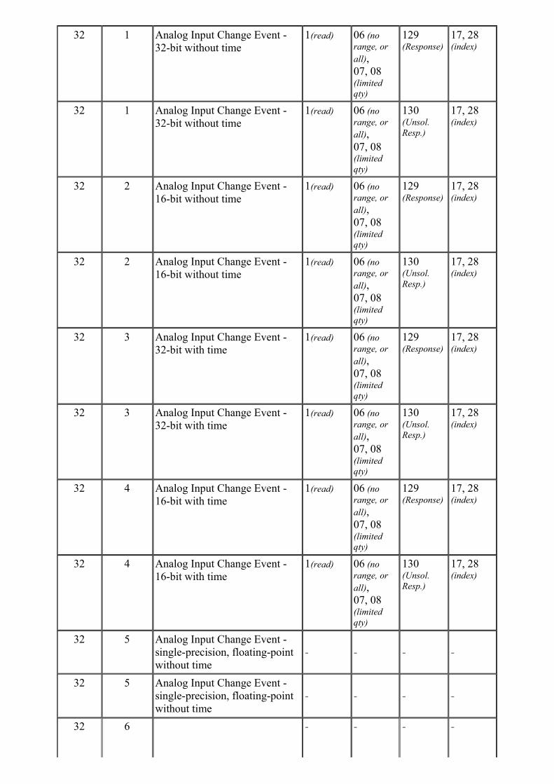
32 1 Analog Input Change Event -
32-bit without time
1(read) 06 (no
range, or
all),
07, 08(limited
qty)
129(Response)
17, 28(index)
32 1 Analog Input Change Event -
32-bit without time
1(read) 06 (no
range, or
all),
07, 08(limited
qty)
130(Unsol.
Resp.)
17, 28(index)
32 2 Analog Input Change Event -
16-bit without time
1(read) 06 (no
range, or
all),
07, 08(limited
qty)
129(Response)
17, 28(index)
32 2 Analog Input Change Event -
16-bit without time
1(read) 06 (no
range, or
all),
07, 08(limited
qty)
130(Unsol.
Resp.)
17, 28(index)
32 3 Analog Input Change Event -
32-bit with time
1(read) 06 (no
range, or
all),
07, 08(limited
qty)
129(Response)
17, 28(index)
32 3 Analog Input Change Event -
32-bit with time
1(read) 06 (no
range, or
all),
07, 08(limited
qty)
130(Unsol.
Resp.)
17, 28(index)
32 4 Analog Input Change Event -
16-bit with time
1(read) 06 (no
range, or
all),
07, 08(limited
qty)
129(Response)
17, 28(index)
32 4 Analog Input Change Event -
16-bit with time
1(read) 06 (no
range, or
all),
07, 08(limited
qty)
130(Unsol.
Resp.)
17, 28(index)
32 5 Analog Input Change Event -
single-precision, floating-point
without time
- - - -
32 5 Analog Input Change Event -
single-precision, floating-point
without time
- - - -
32 6 - - - -
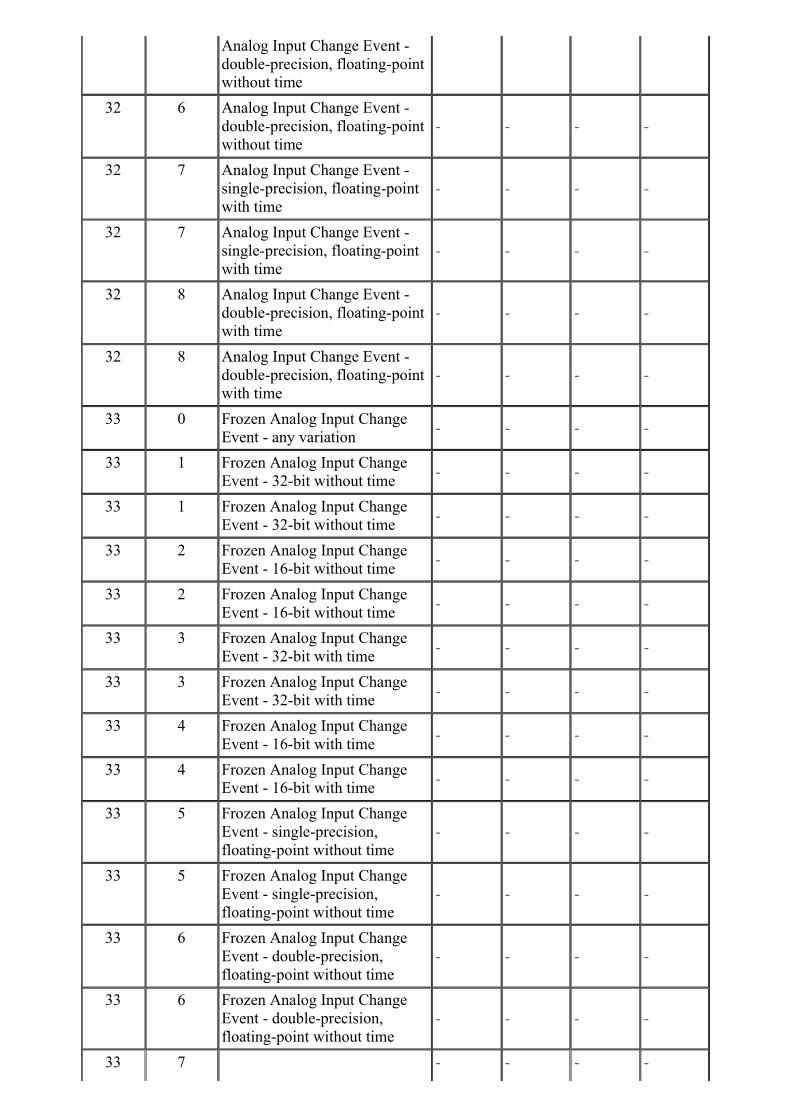
Analog Input Change Event -
double-precision, floating-point
without time
32 6 Analog Input Change Event -
double-precision, floating-point
without time
- - - -
32 7 Analog Input Change Event -
single-precision, floating-point
with time
- - - -
32 7 Analog Input Change Event -
single-precision, floating-point
with time
- - - -
32 8 Analog Input Change Event -
double-precision, floating-point
with time
- - - -
32 8 Analog Input Change Event -
double-precision, floating-point
with time
- - - -
33 0 Frozen Analog Input Change
Event - any variation- - - -
33 1 Frozen Analog Input Change
Event - 32-bit without time- - - -
33 1 Frozen Analog Input Change
Event - 32-bit without time- - - -
33 2 Frozen Analog Input Change
Event - 16-bit without time- - - -
33 2 Frozen Analog Input Change
Event - 16-bit without time- - - -
33 3 Frozen Analog Input Change
Event - 32-bit with time- - - -
33 3 Frozen Analog Input Change
Event - 32-bit with time- - - -
33 4 Frozen Analog Input Change
Event - 16-bit with time- - - -
33 4 Frozen Analog Input Change
Event - 16-bit with time- - - -
33 5 Frozen Analog Input Change
Event - single-precision,
floating-point without time
- - - -
33 5 Frozen Analog Input Change
Event - single-precision,
floating-point without time
- - - -
33 6 Frozen Analog Input Change
Event - double-precision,
floating-point without time
- - - -
33 6 Frozen Analog Input Change
Event - double-precision,
floating-point without time
- - - -
33 7 - - - -
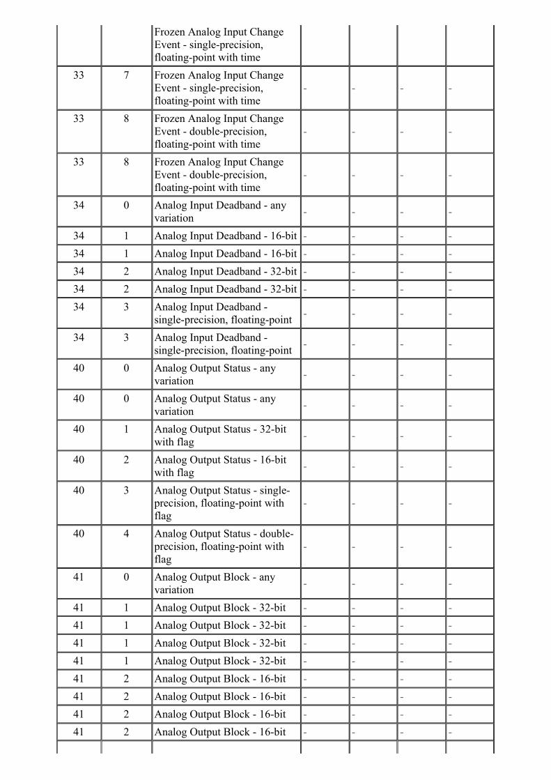
Frozen Analog Input Change
Event - single-precision,
floating-point with time
33 7 Frozen Analog Input Change
Event - single-precision,
floating-point with time
- - - -
33 8 Frozen Analog Input Change
Event - double-precision,
floating-point with time
- - - -
33 8 Frozen Analog Input Change
Event - double-precision,
floating-point with time
- - - -
34 0 Analog Input Deadband - any
variation- - - -
34 1 Analog Input Deadband - 16-bit - - - -
34 1 Analog Input Deadband - 16-bit - - - -
34 2 Analog Input Deadband - 32-bit - - - -
34 2 Analog Input Deadband - 32-bit - - - -
34 3 Analog Input Deadband -
single-precision, floating-point- - - -
34 3 Analog Input Deadband -
single-precision, floating-point- - - -
40 0 Analog Output Status - any
variation- - - -
40 0 Analog Output Status - any
variation- - - -
40 1 Analog Output Status - 32-bit
with flag- - - -
40 2 Analog Output Status - 16-bit
with flag- - - -
40 3 Analog Output Status - single-
precision, floating-point with
flag
- - - -
40 4 Analog Output Status - double-
precision, floating-point with
flag
- - - -
41 0 Analog Output Block - any
variation- - - -
41 1 Analog Output Block - 32-bit - - - -
41 1 Analog Output Block - 32-bit - - - -
41 1 Analog Output Block - 32-bit - - - -
41 1 Analog Output Block - 32-bit - - - -
41 2 Analog Output Block - 16-bit - - - -
41 2 Analog Output Block - 16-bit - - - -
41 2 Analog Output Block - 16-bit - - - -
41 2 Analog Output Block - 16-bit - - - -
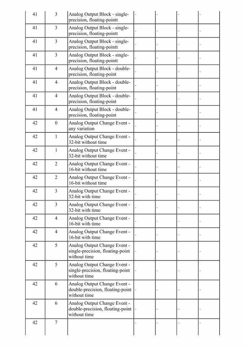
41 3 Analog Output Block - single-
precision, floating-pointt
- - - -
41 3 Analog Output Block - single-
precision, floating-pointt- - - -
41 3 Analog Output Block - single-
precision, floating-pointt- - - -
41 3 Analog Output Block - single-
precision, floating-pointt- - - -
41 4 Analog Output Block - double-
precision, floating-point- - - -
41 4 Analog Output Block - double-
precision, floating-point- - - -
41 4 Analog Output Block - double-
precision, floating-point- - - -
41 4 Analog Output Block - double-
precision, floating-point- - - -
42 0 Analog Output Change Event -
any variation- - - -
42 1 Analog Output Change Event -
32-bit without time- - - -
42 1 Analog Output Change Event -
32-bit without time- - - -
42 2 Analog Output Change Event -
16-bit without time- - - -
42 2 Analog Output Change Event -
16-bit without time- - - -
42 3 Analog Output Change Event -
32-bit with time- - - -
42 3 Analog Output Change Event -
32-bit with time- - - -
42 4 Analog Output Change Event -
16-bit with time- - - -
42 4 Analog Output Change Event -
16-bit with time- - - -
42 5 Analog Output Change Event -
single-precision, floating-point
without time
- - - -
42 5 Analog Output Change Event -
single-precision, floating-point
without time
- - - -
42 6 Analog Output Change Event -
double-precision, floating-point
without time
- - - -
42 6 Analog Output Change Event -
double-precision, floating-point
without time
- - - -
42 7 - - - -

Analog Output Change Event -
single-precision, floating-point
with time
42 7 Analog Output Change Event -
single-precision, floating-point
with time
- - - -
42 8 Analog Output Change Event -
double-precision, floating-point
with time
- - - -
42 8 Analog Output Change Event -
double-precision, floating-point
with time
- - - -
43 0 Analog Output Command
Event - any variation- - - -
43 1 Analog Output Command
Event - 32-bit without time- - - -
43 1 Analog Output Command
Event - 32-bit without time- - - -
43 2 Analog Output Command
Event - 16-bit without time- - - -
43 2 Analog Output Command
Event - 16-bit without time- - - -
43 3 Analog Output Command
Event - 32-bit with time- - - -
43 3 Analog Output Command
Event - 32-bit with time- - - -
43 4 Analog Output Command
Event - 16-bit with time- - - -
43 4 Analog Output Command
Event - 16-bit with time- - - -
43 5 Analog Output Command
Event - single-precision,
floating-point without time
- - - -
43 5 Analog Output Command
Event - single-precision,
floating-point without time
- - - -
43 6 Analog Output Command
Event - double-precision,
floating-point without time
- - - -
43 6 Analog Output Command
Event - double-precision,
floating-point without time
- - - -
43 7 Analog Output Command
Event - single-precision,
floating-point with time
- - - -
43 7 Analog Output Command
Event - single-precision,
floating-point with time
- - - -
43 8 - - - -
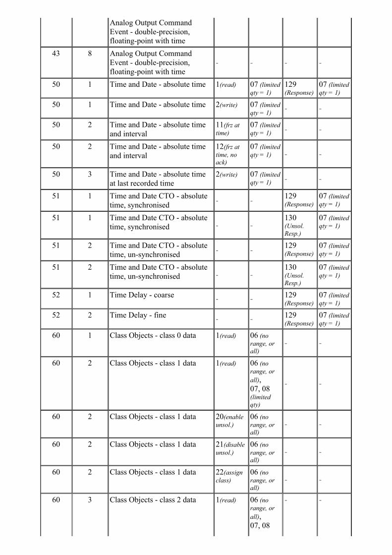
Analog Output Command
Event - double-precision,
floating-point with time
43 8 Analog Output Command
Event - double-precision,
floating-point with time
- - - -
50 1 Time and Date - absolute time 1(read) 07 (limited
qty = 1)
129(Response)
07 (limited
qty = 1)
50 1 Time and Date - absolute time 2(write) 07 (limited
qty = 1)- -
50 2 Time and Date - absolute time
and interval
11(frz at
time)
07 (limited
qty = 1)- -
50 2 Time and Date - absolute time
and interval
12(frz at
time, no
ack)
07 (limited
qty = 1) - -
50 3 Time and Date - absolute time
at last recorded time
2(write) 07 (limited
qty = 1)- -
51 1 Time and Date CTO - absolute
time, synchronised- -
129(Response)
07 (limited
qty = 1)
51 1 Time and Date CTO - absolute
time, synchronised - -130(Unsol.
Resp.)
07 (limited
qty = 1)
51 2 Time and Date CTO - absolute
time, un-synchronised- -
129(Response)
07 (limited
qty = 1)
51 2 Time and Date CTO - absolute
time, un-synchronised - -130(Unsol.
Resp.)
07 (limited
qty = 1)
52 1 Time Delay - coarse- -
129(Response)
07 (limited
qty = 1)
52 2 Time Delay - fine- -
129(Response)
07 (limited
qty = 1)
60 1 Class Objects - class 0 data 1(read) 06 (no
range, or
all)
- -
60 2 Class Objects - class 1 data 1(read) 06 (no
range, or
all),
07, 08(limited
qty)
- -
60 2 Class Objects - class 1 data 20(enable
unsol.)
06 (no
range, or
all)
- -
60 2 Class Objects - class 1 data 21(disable
unsol.)
06 (no
range, or
all)
- -
60 2 Class Objects - class 1 data 22(assign
class)
06 (no
range, or
all)
- -
60 3 Class Objects - class 2 data 1(read) 06 (no
range, or
all),
07, 08
- -
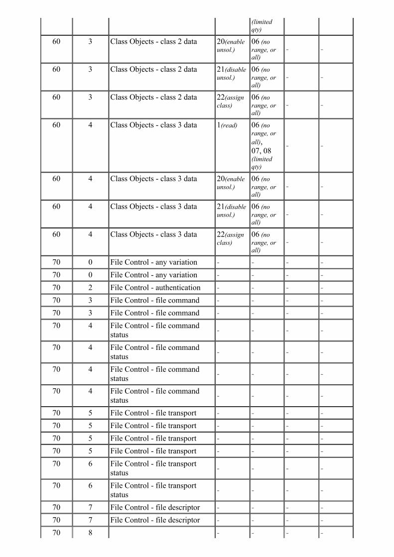
(limited
qty)
60 3 Class Objects - class 2 data 20(enable
unsol.)
06 (no
range, or
all)
- -
60 3 Class Objects - class 2 data 21(disable
unsol.)
06 (no
range, or
all)
- -
60 3 Class Objects - class 2 data 22(assign
class)
06 (no
range, or
all)
- -
60 4 Class Objects - class 3 data 1(read) 06 (no
range, or
all),
07, 08(limited
qty)
- -
60 4 Class Objects - class 3 data 20(enable
unsol.)
06 (no
range, or
all)
- -
60 4 Class Objects - class 3 data 21(disable
unsol.)
06 (no
range, or
all)
- -
60 4 Class Objects - class 3 data 22(assign
class)
06 (no
range, or
all)
- -
70 0 File Control - any variation - - - -
70 0 File Control - any variation - - - -
70 2 File Control - authentication - - - -
70 3 File Control - file command - - - -
70 3 File Control - file command - - - -
70 4 File Control - file command
status- - - -
70 4 File Control - file command
status- - - -
70 4 File Control - file command
status- - - -
70 4 File Control - file command
status- - - -
70 5 File Control - file transport - - - -
70 5 File Control - file transport - - - -
70 5 File Control - file transport - - - -
70 5 File Control - file transport - - - -
70 6 File Control - file transport
status- - - -
70 6 File Control - file transport
status- - - -
70 7 File Control - file descriptor - - - -
70 7 File Control - file descriptor - - - -
70 8 - - - -

File Control - file specification
string
80 1 Internal Indications - packed
format
1(read) 00, 01(start-stop)
129(Response)
00, 01(start-stop)
80 1 Internal Indications - packed
format
2(write) 00 (start-
stop)- -
85 0 Data Set Prototype - any
variation- - - -
85 1 Data Set Prototype - with UUID - - - -
85 1 Data Set Prototype - with UUID - - - -
86 0 Data Set Descriptor - any
variation- - - -
86 0 Data Set Descriptor - any
variation- - - -
86 1 Data Set Descriptor - Data Set
contents- - - -
86 1 Data Set Descriptor - Data Set
contents- - - -
86 2 Data Set Descriptor -
characteristics- - - -
86 3 Data Set Descriptor - point
index attributes- - - -
86 3 Data Set Descriptor - point
index attributes- - - -
87 1 Data Set - present value - - - -
87 1 Data Set - present value - - - -
88 0 Data Set Event - any variation - - - -
88 1 Data Set Event - snapshot - - - -
88 1 Data Set Event - snapshot - - - -
91 1 Status of Requested Operation - - - -
101 1 Binary Coded Decimal Integers
- small- - - -
101 2 Binary Coded Decimal Integers
- medium- - - -
101 3 Binary Coded Decimal Integers
- large- - - -
110 255 Octet String - - - -
110 255 Octet String - - - -
111 255 Octet String Change Event - - - -
111 255 Octet String Change Event - - - -
112 255 Virtual Terminal Output Block - - - -
113 255 Virtual Terminal Event Data - - - -
113 255 Virtual Terminal Event Data - - - -

---------- End of Device Profile for Reference Device ----------
------------------------------- End of Complete Device Profile -------------------------------