dns 8 live dialogue noise suppressor - cedar audio · pdf filedns 8 live dialogue noise...
TRANSCRIPT

Page 1
Owner’S Manual© 2012 - 2014 CeDar audio ltd
Manual version 3.00: January 2014
DNS 8 Livedialogue noise suppressor

Page 2
Intentionally left blank

Page 3
Table of Contents
an Introduction to the DnS 8 live ................................................................ 4
Safety instructions ........................................................................................ 5
Setting up the DnS 8 live ............................................................................ 6
Operation ...................................................................................................... 8Summary view ......................................................................................... 8Summary view: single-channel tutorial ................................................. 10Multi-channel use .................................................................................. 11Detail view ............................................................................................. 12Detail view: tutorial ................................................................................ 13
Menus ......................................................................................................... 14Moving and editing within menus ......................................................... 15Status .................................................................................................... 15Presets .................................................................................................. 16Setup ..................................................................................................... 18
remote control ........................................................................................... 21
Firmware upgrades .................................................................................... 22
Declaration of conformity ........................................................................... 23
Contact information ................................................................................... 24
Specifications ............................................................................................. 25
licence and limited warranty ................................................................... 26

Page 4
An IntroductIon to the dnS 8 LIve
The DNS 8 Live is a further development of the DNS technology first introduced in the Academy Award winning DNS1000, and it is designed specifically for live use. Offering eight simultaneous channels of dialogue noise suppression, it hosts a new DNS algorithm boasting a simplified ‘2-knob’ approach as well as a detailed editing mode that offers more flexibility and control than any previous dialogue noise suppressor. nonetheless, it retains the near-zero latency of its predecessors and, with its 4-pin 12VDC power socket and remote control capabilities, it’s suitable for use in all live situations - not just live-to-air broadcasting, but also live sound in venues such as theatres, concert halls, conferences venues, and places of worship.
The DnS 8 live operates by dividing incoming signals into a large number of spectral bands. Sophisticated filters analyse each of these and then suppress the noise independently in each channel. The innovative design of the filter bank eliminates the need to select the range of frequencies in which the unit will operate, and it is not necessary to adjust the amount of attenuation in individual bands unless you wish to do so.
Quality, speed and simplicity are paramount considerations in the DnS 8 live, which offers the following:
■ Near zero latencya group delay of less than 10 samples (typically less than 1/200th of a frame) so there is no loss of lip-sync.
■ FlexibilityThe ability to handle a wide range of noise suppression requirements.
■ Speed and ease of useA carefully designed user-interface that maximises speed of use.
■ Audio interfaces24-bit digital audio interfaces conforming to AES/EBU standards.
■ Universal mains power supply and 12VDC powerThe ability to work anywhere in the world.
■ Powerful processorsThe latest, high resolution floating-point processors to ensure that it will handle the most complex processing requirements.
■ Remote ControlThe ability to monitor and adjust all audio processing parameters using a range of common web browsers.
Page 5
SAfety InStructIonS
read these instructions, and follow them.
■ Water and moisture The DNS 8 Live must not be exposed to rain or moisture. Furthermore, if it
is brought directly from a cold environment into a warm one, moisture may condense inside it. This, in itself, will not cause damage, but may cause electrical shorting. This could damage the unit, and even cause danger to life. always allow the unit to reach ambient temperatures naturally before connecting the mains power.
■ Mounting and ventilation You should place the DNS 8 Live on a flat, stable surface or mount it in
a standard 19” equipment rack. use the supplied rubber feet to avoid scratching the surface, or the rackmounting accessories, as appropriate.
Do not subject the unit to strong sunlight, excessive dust, mechanical vibration or periodic shocks. It is not susceptible to excessive heat build-up, but should be installed away from heat sources such as radiators and audio devices that produce large amounts of heat.
■ Connections Turn off the power to all equipment before making any connections.
■ Cleaning Clean the DnS 8 live only with a dry cloth. never use abrasive pads or
liquid cleaners such as alcohol or benzene.
■ Damage requiring service The DnS 8 live contains no user-serviceable parts and should on no
account be opened or dismantled by unauthorised personnel. A unit should be returned to qualified service agents when it has been
exposed to liquids, when it fails to function correctly, when it has been dropped, or when the case is damaged.

Page 6
SettIng up the dnS 8 LIve
unpack the DnS 8 live carefully. Save the carton and all packing materials since you may need them to transport the unit in the future. In addition to the DnS 8 live and its packaging, the box should contain the following:■ this manual in paper or electronic form■ mains connection lead■ four rubber feet■ warranty registration cardTo maintain reliability and prolong operating life, observe the following environmental considerations:■ the temperature should be maintained between 5 and 30 Celsius■ relative humidity should be in the range 30% to 80% non-condensing■ strong magnetic fields should not exist nearby.
Power sources
The DnS 8 live features a universal aC power supply that will work safely on any mains supply in the range 85V to 260V, 50/60Hz aC only. a unit used in this way should always be grounded (earthed), and you should route power cables so that they will not be walked on or pinched.
a 12VDC input is also provided. Both power inputs may be connected simultaneously, in which case the aC input will be used to power the unit. when both inputs are connected, you may disconnect the aC input and the unit will continue to operate on DC power without shutting down or restarting.
Audio connections
The DnS 8 live offers two audio connection standards. It passes its signal to both outputs irrespective of the input used. The standards are: ■ Digital aeS3 format on standard aeS/eBu Xlr connectors■ Digital aeS3 format on a DB25 connector conforming to aeS59The unit will by default lock to any aeS/eBu signal with sample rate up to 96kHz that is presented to the rear panel. If the input signal lies outside the industry tolerances for any of the standard sample rates, the filter table for the nearest standard will be used and scaled accordingly. The DnS 8 live is not affected by channel status data. It will echo any such data directly to the outputs.
In order to comply with eMC regulations, you must connect the DnS 8 live using metal-shelled connectors and good quality shielded cable suitable for digital audio.

Page 7
AES/EBU pin-out for theDB25 connector
View from rear of unit
Channels PinHot Cold Grd
In 1 & 2 24 12 253 & 4 10 23 115 & 6 21 9 227 & 8 7 20 8
Out 1 & 2 18 6 193 & 4 4 17 55 & 6 15 3 167 & 8 1 14 2
unused:13
Fail-safe bypass
DnS 8 live units from serial number DnS-8-00992 onward have a fail-safe bypass fitted as standard. Firmware v1.1.3 or later is required for this to operate correctly.
In the event of a power failure (or certain other major malfunctions) the Xlr inputs become connected directly to the Xlr outputs by relays, bypassing the active electronics of the unit. Once triggered, the fail-safe bypass can be cleared by power-cycling the unit. note that the fail-safe bypass does not apply to signals presented to the DB25 connector.
Audio output synchronisation
a BnC connector is provided. This will accept a DarS synchronisation signal conforming to aeS11 or squarewave wordclock at the nominal sample rate.
The BnC sync input can be terminated (75Ohms) using the recessed rear panel switch.
IMPORTANT NOTE:
The digital audio signals feeding the DnS 8 live must be at the same sample rate and synchronous or clicks, ticks, or even loud broadband noise may result from the consequent data errors.
Ethernet
The Ethernet connection allows you to upgrade the firmware (if required) and to control the DnS 8 live using a standard web browser.
The MaC address is stated on the label on the rear panel of the unit and within the status page.
Page 8
operAtIon
Power on/off
Switch the DnS 8 live on by pressing the power button.
Switch it off by pressing and holding the power button for five seconds. The current settings will be stored during shutdown. If the unit is not shut down in this manner, the settings will not be stored and corruption of the internal memory may result. refer to Setup/Options for further information.
SummAry vIew
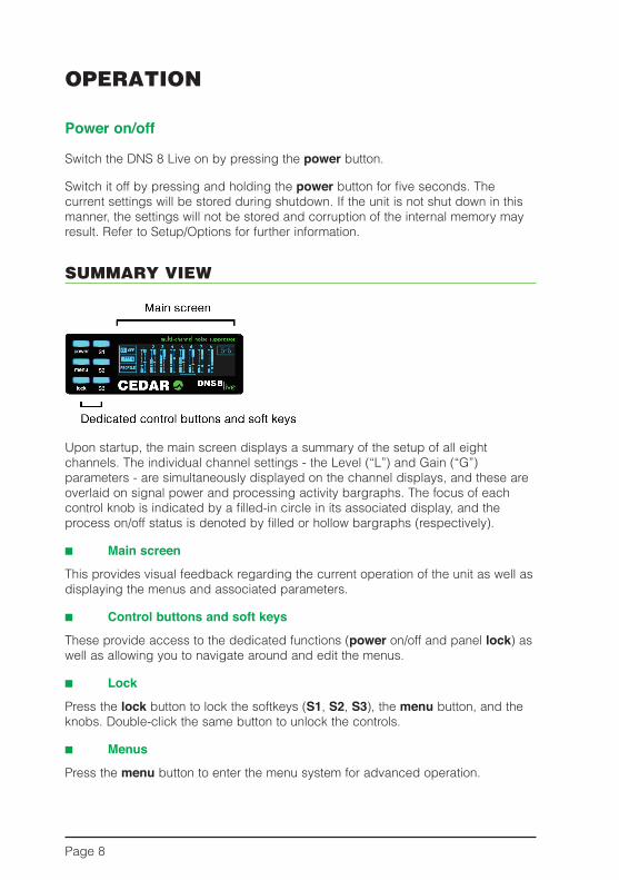
upon startup, the main screen displays a summary of the setup of all eight channels. The individual channel settings - the level (“l”) and Gain (“G”) parameters - are simultaneously displayed on the channel displays, and these are overlaid on signal power and processing activity bargraphs. The focus of each control knob is indicated by a filled-in circle in its associated display, and the process on/off status is denoted by filled or hollow bargraphs (respectively).
■ Main screen
This provides visual feedback regarding the current operation of the unit as well as displaying the menus and associated parameters.
■ Control buttons and soft keys
These provide access to the dedicated functions (power on/off and panel lock) as well as allowing you to navigate around and edit the menus.
■ Lock
Press the lock button to lock the softkeys (S1, S2, S3), the menu button, and the knobs. Double-click the same button to unlock the controls.
■ Menus
Press the menu button to enter the menu system for advanced operation.

Page 9
■ Softkeys (S1, S2, S3)
When first switched on, the soft keys perform the following tasks. For explanations of the Groups and learn Mode mentioned in this table, please refer to the relevant sections below.
S1 (DNS On)
Click: toggle the current channel/group on/offPress/Hold/release: preview the current channel/group on/offDouble-click: toggle global on/off
S2 (Learn)
Click: start learning on the current channel/group.Click again to stop
Press/hold/release: learn on the current channel/group while pressedDouble-click: toggle global learn
S3 (Detail)
Click: toggle between Detail and default (summary) viewsPress/hold/release: preview the detail of the current channel/group on the
main screen
■ Channel displays
In basic use, the two bar graphs in each channel display show the incoming signal level (the left-hand bar) and the maximum amount of attenuation (the right-hand bar) at any given moment in that channel. These are overlaid with a visual indication of values of the level and Gain parameters for that channel.
■ Level / Gain knobs
In basic use, these allow you to tell the DnS 8 live how much noise is present in the signal presented to each input and the amount by which you wish to attenuate it.
The full range of operations is shown overleaf:

Page 10
rotate: adjust the level/gainClick: toggle the focus between the level and gainDouble-click: toggle the process on/off in that channelPress/Hold/release: preview process on/off in that channelMulti-click: click two encoders near-simultaneously to create/delete
channel groups (see below)
SummAry vIew: SIngLe-chAnneL tutorIAL
ensure that the channel you are interested in processing is the channel in focus (clicking on its knob will do this) and that the DnS process is switched on.
You now need to set the level and Gain parameters for this channel, which may be accomplished automatically using the learn function, or manually.
Setting the Level and Gain using the Learn function
Identify a period when there is no wanted signal present in the audio. Press and hold S2 (learn) for a second or two, during which time the unit will analyse the noise and begin to suppress it. release S2 before the wanted signal returns. In many cases the unit will now suppress the noise effectively, but you can now refine level and Gain settings if necessary.
Setting the Level and Gain manually
First, you need to identify the noise level of the audio in the signal, and adjust the level control appropriately. Click the knob (if necessary) to highlight the righthand fader “G” (Gain). Turn the knob anticlockwise to reduce the Gain to its minimum. Maximum processing is now occurring, which makes it easier to determine the noise level in that channel. now click the encoder to highlight the “l” (level) fader and, starting at its lowest setting, raise this slowly. At first, you will hear very little happen but, at some point determined by the noise content of the signal, you will hear the noise disappear. You should attempt to find the lowest point at which this occurs.
Finally you need to set an appropriate amount of noise suppression using the Gain control. Click the knob to switch to this, and then find the position for the Gain that suppresses as much noise as possible without introducing unwanted artefacts into the desired signal.
Process On/Off
while determining the settings, you can bypass processing by pressing and holding the channel knob (preview), or by double-clicking on the channel knob (toggle processing on/off), or by pressing S1. each of these methods allows you to audition the signal before and after processing to ensure optimal results.

Page 11
muLtI-chAnneL uSe
Having achieved an acceptable result for one channel, you should now proceed to monitor each of the other channels to be processed (if any) and set these up as above.
Groups
Grouping channels together makes them adopt identical settings, and allows them to be adjusted together. For optimal results, the noise characteristics of all channels of the group need to be similar. This might be the case, for example, for groups of similar microphones located in the same environment.
Group channels by clicking two knobs simultaneously or in quick succession. For example, pressing knobs 1 and 4 will group channels 1, 2, 3 and 4 together. Pressing them again removes the grouping. when channels are grouped, you can adjust their Levels and Gains using any of the grouped knobs. For example, if you highlight the “l” fader in channel 1 and the “G” fader in channel 2 you can control the levels and Gains simultaneously in all four channels using just knobs 1 and 2.
The learn function works simultaneously for all channels in a group, analysing all of them simultaneously to find settings that are - as much as possible - appropriate for all of the channels within the group.
You may set up any combination of individual channels and groups provided that the following criteria are met:
• All channels in a group must be adjacent.• No channel can be in two groups simultaneously.
This architecture allows you to create desirable combinations such as dual 4-channel operation, or four stereo pairs.
Page 12
detAIL vIew
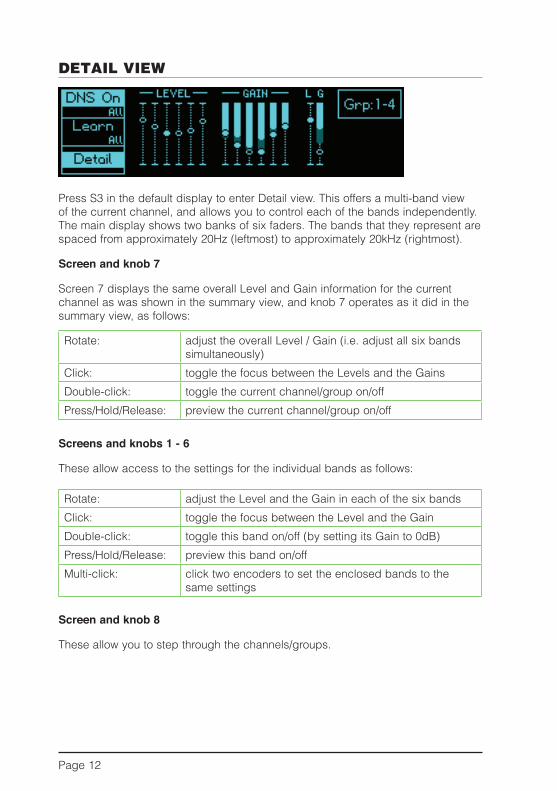
Press S3 in the default display to enter Detail view. This offers a multi-band view of the current channel, and allows you to control each of the bands independently. The main display shows two banks of six faders. The bands that they represent are spaced from approximately 20Hz (leftmost) to approximately 20kHz (rightmost).
Screen and knob 7
Screen 7 displays the same overall level and Gain information for the current channel as was shown in the summary view, and knob 7 operates as it did in the summary view, as follows:
rotate: adjust the overall Level / Gain (i.e. adjust all six bands simultaneously)
Click: toggle the focus between the levels and the GainsDouble-click: toggle the current channel/group on/offPress/Hold/release: preview the current channel/group on/off
Screens and knobs 1 - 6
These allow access to the settings for the individual bands as follows:
rotate: adjust the Level and the Gain in each of the six bandsClick: toggle the focus between the level and the GainDouble-click: toggle this band on/off (by setting its Gain to 0dB)Press/Hold/release: preview this band on/offMulti-click: click two encoders to set the enclosed bands to the
same settings
Screen and knob 8
These allow you to step through the channels/groups.

Page 13
detAIL vIew: tutorIAL
Adjusting the settings in Detail view is an extension of setting them in the summary view described above. To do this manually for each band, you would follow the same procedure:
• Set all the Level and Gain controls to minimum (Level= -80 and Gain= -20).• Gradually increase the Level until the noise in that band disappears.• Refine the Gain settings to achieve an appropriate degree of noise
suppression without artefacts.
However, it is unlikely that you will have to do this because you will be starting from the (approximately) correct settings derived using the summary view, or obtained from the Learn function. In either case, it should only be necessary to refine the settings.
Note: You can also operate the Learn function in Detail view, whereupon you will see it adjusting the settings in real time.
Pressing and holding any of knobs 1 - 6 temporarily switches that band off, allowing you to hear the effects of noise suppression in that band alone.
Example
You may find that, for a given piece of audio, the greatest effect comes from bands 3 and 4. This suggests that the noise is concentrated in the mid frequencies, so higher level settings and lower gain settings are appropriate for bands 3 and 4, whereas the gains of bands 1, 2, 5 and 6 should remain relatively close to 0dB to ensure that minimal signal damage occurs in the bands that do not contain much noise.
The final configuration may look like this:

Page 14
menuS
Select the menus by pressing the menu button. Select the desired submenu by pressing the S1, S2 and S3 buttons. when appropriate, press the menu button to return to the previous screen.
The menu map is as follows:
Edit
Apply
Cancel
Status
Audio
Setup
Statusinformation
Presets
Network
RecallEdit Save
PrevUp
NextDown
Options
Edit
Erase Clr
ApplyCncl Del
Edit
Apply
Cancel
Edit
Apply
Cancel

Page 15
movIng And edItIng wIthIn menuS
Some menus provide options to move around on screen and to edit characters or values in specific locations.
Moving is accomplished using knob 1 when it shows the following in its associated screen:
editing is accomplished using knob 2 when it shows the following in its associated screen:
StAtuS
The status page reports the current audio and network status of the DnS 8 live. no editing is possible on this page.
In the example above, 44.1kHz audio is being received on channels 1 and 2 of the Xlr inputs, but no audio is being received on channels 3 to 8. no aeS11 sync signal has been detected at the BnC input.
The page is also reporting the unit’s MaC and IP addresses.
Note: IftheInputfieldshows‘!BYP!’thenthefail-safebypasshasbeentriggeredandtheunitmustbepower-cycledtoclearit.

Page 16
preSetS
The DnS 8 live contains 100 memory locations (“presets”) numbered 00 to 99. each memory stores the process settings of all eight channels, including grouping when appropriate. Memories do not store information such as the I/O selection.
Press the menu button followed by S2 (Presets) to enter the preset manager.
note: The eight channel displays will continue to show the Summary or Detail views (as appropriate) so you can continue to control the DNS 8 Live while saving and recalling presets.
The Preset manager screen
The three possible actions on each of the softkeys perform the following functions:
S1 (Recall / Edit / Save)
Click: recall the selected presetPress/Hold/release: invoke the edit screen to edit the preset name or to
delete the presetDouble-click: save the current process state to the selected preset
S2 (Prev / Up)
Click: select previous presetPress/hold/release: scroll up the preset listDouble-click: no action
S3 (Next / Down)
Click: select next presetPress/hold/release scroll down the preset listDouble-click no action
Note: InPresetmode,theeightknobsandtheirassociatedscreenscontinueto edit and display the appropriate (Summary or Detail) processing parameters, allowing you to continue controlling the DNS 8 Live.

Page 17
The Edit screen
when edit screen is selected, the channel 1 and 2 knobs allow you to edit the name of the current preset in the usual fashion.
S1 (Edit)
Click: no actionPress/Hold/release: no actionDouble-click: no action
S2 (Erase / Clr)
Click: erase the character under the cursor or to the left of the cursor if it is positioned at the end of the name
Press/hold/release: no actionDouble-click: clear the entire name
S3 (Apply / Cncl / Del)
Click: apply changesPress/hold/release: cancel changesDouble-click: delete the preset
Note: Itisnotpossibletostoreapresetwithnoname.Ifthenamefieldisempty,the Apply option will change to Delete and will delete the preset.

Page 18
Setup
Press S3 Setup in the default or detail screens to access the three setup options.
Click on S1, S2 or S3 to enter the audio, Options and network screens respectively. Having done so, all three pages offer the same edit options:
S1 (Edit)
Click: edit the fields (see below)
S2 (Apply)
Click: apply the changes
S3 (Cancel)
Click: cancel the changes
The Audio screen
Lock
The lock field reports which channels are locked to a valid source. In the example above, channels 1 and 2 are receiving valid data; channels 3 to 8 are not.
Rate
The sample rate is derived from the lowest numbered channel that is receiving a valid signal unless aeS11 wordclock is being accepted at the BnC input, in which case the sample rate will be derived from that.
Note: Thedigitalaudiosignalsfeedingtheunitmustbeatthesamesamplerateand synchronous or loud noise may result from the consequent data errors.

Page 19
Audio and wordclock sources
Select the desired audio and wordclock sources.
Input
Xlr3: audio is accepted from the Xlr inputsDB25: audio is accepted from the DB25 input
Sync
Input: wordclock is derived from the lowest numbered input channel that has lock
BnC: aeS11 wordclock is used if detected at the BnC input, otherwise the display will report wClK and assume that standard wordclock is being received.
The Options screen
Click time: Determines the desired window for a double-click in the range 160ms - 640ms
You may test the response using knob 8, which will report whether it interprets your presses as a click, a click/hold or a double-click
Brightness: Determines the brightness for the buttons and the screens, which may be set independently
Boot option: Determines the settings loaded when you restart the unit:
Load defaultsloads the factory settingsRestore lastloads the settings in use when you last switched off the unitLoad preset 00loads the settings stored in preset 00, thus allowing you to create your own default settings

Page 20
The Network screen
Username and password
use this window to set the username and password that will be requested by web browsers to enable remote control of the unit. (See next page.) The defaults are: username: DnS8live Password: <none>The username and password are case-sensitive.
IP settings
Use these fields to select the desired IP settings. (Most networks have a DHCP server that will automatically configure the DNS 8 Live to work on the network, so it is unlikely that you will need to adjust anything on this page when DHCP is On.)
DHCP
On Dynamic Host Configuration Protocol automatically sets up the unit to work on your local network. no manual changes to the addresses are possible in this mode
Off configure the unit address, netmask and gateway manually
Address: Set the unit’s address manuallyNetmask: Set the netmask manuallyGateway: Set the gateway address manually
Note for network administrators
The DnS 8 live sends its serial number as its host name in DHCP requests. If your DHCP server registers host names in the domain name server, you can access your DnS 8 live as dns-8-xxxxx.yourdomain.com instead of directly by its numeric IP address.
When configured correctly, the DNS 8 Live will respond to ICMP echo requests (pings).

Page 21
remote controL
The DnS 8 live incorporates its remote control software in the form of an internal web page, and you may connect to this using a suitable browser.
Connect the DnS 8 live to your ethernet network and enter its address into your browser’s address bar. (See note on previous page.) enter the Username and Password for the unit and you will obtain two panels corresponding to the Summary and Detail screens displayed on the DnS 8 live itself. These panels can be hidden and shown using the buttons in the upper left-hand corner of the screen.
The Presets button (top right) provides access to the presets, and the Summary panel displays Group buttons that allow you to group and ungroup channels. at the bottom of the screen you will find global DNS On/Off and Learn buttons.
Compatibility
at the time of writing, the DnS 8 live is compatible with current versions of Chrome, Explorer (v9 and higher), Firefox, Opera and Safari. It may be accessed by multiple browsers simultaneously, and changes made on one browser will be displayed on any others connected to the unit. However, the company does not guarantee error-free use in this manner, and multi-client use is not supported by CeDar audio ltd.

Page 22
fIrmwAre upgrAdeS
The DNS 8 Live firmware may be upgraded over the network using a standard web browser.
Determine the address of your DnS 8 live by inspecting the Status window, then launch your browser and type the following into the address bar…
xxx.xxx.xxx.xxx/upload.cgi
…where xxx.xxx.xxx.xxx is that address.
The following screen (or a similar one performing the same function, depending upon browser) will appear.
Click on Browse and navigate to the new firmware, which will have been downloaded from the web or sent to you directly by CeDar audio ltd.
Click on Upload.
Depending upon the page displayed on the DnS 8 live, you may notice the letters “T” and “r” blinking on its main screen. This is normal, and indicates that the unit is transmitting and receiving data.
when the upload is complete, press Reboot to restart the unit.
The software also allows you to return to a previous version of the firmware. Click on Downgrade to remove the most recent version and then click on Reboot.

Page 23
decLArAtIon of conformIty
Date of issue 30 September 2012equipment CeDar DnS 8 lIVeManufacturer CeDar audio ltdaddress 20 Home end, Fulbourn, Cambridge CB21 5BS, uK
This is to certify that the aforementioned equipment, when used in accordance with the instructions in this manual, fully conforms to the protection requirements of the following EC Council Directives: on the approximation of the laws of the member states relating to:
■ 2004/108/eeC electromagnetic Compatibility Directive applicable standards: en 61000-6-1:2007 en 61000-6-3:2007+a1:2011■ 2006/95/eC low Voltage Directive applicable standard: en 60065:2002+a12:2011
Restriction of Hazardous Substances (RoHS) Directive
all hardware products and sub-assemblies manufactured by CeDar audio ltd are designed to be compliant with Directive 2002/95/eC, restriction of Hazardous Substances. The manufacturing processes include the assembly of purchased components and/or sub-assemblies from various sources. any statement of roHS compliance made by CeDar audio ltd may be based, in part or in full, on statements provided by suppliers. Thus whilst every effort is made to ensure compliance, CeDar audio ltd may not have undertaken independent tests to establish the compliance of such components and/or sub-assemblies.
Waste Electrical and Electronic Equipment (WEEE) Directive
In accordance with Directive 2002/96/eC, waste electrical and electronic equipment, CeDar audio ltd will be happy to provide its customers with information about local organisations that can reprocess CeDar products that have reached their end of use. alternatively such products can be returned to CeDar audio ltd in the uK at the owner’s cost and they will then be reprocessed correctly free of charge.
E&OE.The Company reserves the right to change specifications without notice.

Page 24
contAct InformAtIon
Headquarters: CeDar audio ltd,20 Home end, Fulbourn, Cambridge, CB21 5BS, united Kingdom t: +44 1223 881771f: +44 1223 881778 e: [email protected]
USA Office: CeDar audio uSa43 Deerfield Road, Portland, ME 04101-1805, USAt: +1 207 828 0024f: +1 207 773 2422 e: [email protected]
German Office: CeDar DeutschlandGörlitzer Str. 3, D-49525 lengerich, Deutschland t: +49 5481 945087f: +49 5481 945088 e: [email protected]
Web: www.cedaraudio.com
Worldwide Dealer List:
For a current dealer list, please visit www.cedaraudio.com, and click on “Contact us” followed by “worldwide Dealer list”

Page 25
SpecIfIcAtIonS
GeneralPower supply: 85–260VaC; 50–60Hz Power consumption: 15wOverall dimensions: 45 x 483 x 240mm Weight: 3kg (net); 4kg (gross)
AudioI/O type: Digital PCM Sample rates: up to 96kHzI/O resolution: 24 bits Varispeed: approx. ±4%Data format: aeS/eBu Processor power: >3GFlOPslatency: <10 samples Process resolution: 40 bits

Page 26
LIcence And LImIted wArrAnty
1. defInItIonS In this Licence and Limited Warranty the following words and phrases shall bear the following meanings: ‘the Company’ is CEDAR Audio Limited of 20 Home End, Fulbourn, Cambridge CB21 5BS, UK;‘a/the System’ means an instance of the DNS 8 Live sound processing system comprising hardware
and software developed by the Company;‘this Document’ means this Licence and Limited Warranty.
2. ISSue And uSe of the SyStem2.1 The terms and conditions of this Document are implicitly accepted by any person or body corporate who
shall at any time use or have access to the System, and are effective from the date of supply of the System by CEDAR Audio Limited to its immediate customer.
2.2 The Company hereby grants to the Licensee and the Licensee agrees to accept a non-exclusive right to use the System.
3. property And confIdentIALIty3.1 The System contains confidential information of the Company and all copyright, trade marks, trade
names, styles and logos and other intellectual property rights in the System including all documentation and manuals relating thereto are the exclusive property of the Company. The Licensee acknowledges that all such rights are the property of the Company and shall not question or dispute the ownership of any such rights nor use or adopt any trading name or style similar to that of the Company.
3.2 The Licensee shall not attempt to reverse engineer, modify, copy, merge or transcribe the whole or any part of the System or any information or documentation relating thereto.
3.3 The Licensee shall take all reasonable steps to protect the confidential information and intellectual property rights of the Company.
4. LImIted wArrAnty And poSt-wArrAnty oBLIgAtIonS4.1 The Company warrants that a System will perform substantially in accordance with the appropriate
section of its accompanying product manual for a period of one year from the date of supply to the Company‘s immediate customer.
4.2 The Company will make good at its own expenses by repair or replacement any defect or failure that develops in a System within one year of supply to the Company‘s immediate customer.
4.3 The Company shall have no liability to remedy any defect, failure, error or malfunction that arises as a result of any improper use, operation or neglect of a System, or any attempt to repair or modify a System by any person other than the Company or a person appointed with the Company‘s prior written consent.
4.4 In the case of any defect or failure in a System occurring more than twelve months after its supply to the Company‘s immediate customer the Company will at its option and for a reasonable fee make good such defect or failure by repair or replacement (at the option of the Company) subject to the faulty equipment having first been returned to the Company. The Company will use reasonable efforts to return repaired or replacement items promptly, all shipping, handling and insurance costs being for the account of the Licensee.
4.5 The above undertakings 4.1 to 4.4 are accepted by the Licensee in lieu of any other legal remedy in respect of any defect or failure occurring during the said period and of any other obligations or warranties expressed or implied including but not limited to the implied warranties of saleability and fitness for a specific purpose.
4.6 The Licensee hereby acknowledges and accepts that nothing in this Document shall impose upon the Company any obligation to repair or replace any item after a time when it is no longer produced or offered for supply by the Company or which the Company certifies has been superseded by a later version or has become obsolete.
5. force mAJeure The Company shall not be liable for any breach of its obligations hereunder resulting from causes beyond its reasonable control including, but not limited to, fires, strikes (of its own or other employees), insurrection or riots, embargoes, container shortages, wrecks or delays in transportation, inability to obtain supplies and raw materials, or requirements or regulations of any civil or military authority.
Page 27
6. wAIver The waiver by either party of a breach of the provisions hereof by the other shall not be construed as a waiver of any succeeding breach of the same or other provisions, nor shall any delay or omission on the part of either party to exercise any right that it may have under this Licence operate as a waiver of any breach or default by the other party.
7. notIceS Any notices or instruction to be given hereunder shall be delivered or sent by first-class post or telecopier to the other party, and shall be deemed to have been served (if delivered) at the time of delivery or (if sent by post) upon the expiration of seven days after posting or (if sent by telecopier) upon the expiration of twelve hours after transmission.
8. ASSIgnment And SuB-LIcenSIng The Licensee may at his discretion assign a System and in doing so shall assign this License its rights and obligations to the purchaser who shall without reservation agree to be bound by this License. The original Licensee and any subsequent Licensees shall be bound by the obligations of this License in perpetuity.
9. LImItAtIon of LIABILIty The Company‘s maximum liability under any claim including any claim in respect of infringement of the intellectual property rights of any third party shall be, at the option of the Company either: (a) return of a sum calculated as the price received for the System by the Company from its immediate
customer depreciated on a straight line basis over a one year write-off period; or(b) repair or replacement of those components of the System that do not meet the warranties contained
within this Document. The foregoing states the entire liability of the Company to the Licensee.
10. conSeQuentIAL LoSS Even if the Company has been advised of the possibility of such damages, and notwithstanding anything else contained herein the Company shall under no event be liable to the Licensee or to any other persons for loss of profits or contracts or damage (whether direct or consequential) arising in connection with a System or any modification, variation or enhancement thereof and including any documentation or data provided by the Company or for any other indirect or consequential loss.
11. entIre Agreement The Company shall not be liable to the Licensee for any loss arising in connection with any representations, agreements, statements or undertakings made prior to the date of supply of the System to the Licensee.
12. termInAtIon This Licence may be terminated forthwith by the Company if the Licensee commits any material breach of any terms of this License. Forthwith upon such termination the Company shall have immediate right of access to the System for the purpose of removing it.
13. SeverABILIty Notwithstanding that the whole or any part of any provision of this Document may prove to be illegal or unenforceable the other provisions of this Document and the remainder of the provision in question shall remain in full force and effect.
14. heAdIngS The headings to the Clauses are for ease of reference only and shall not affect the interpretation or construction of this Document.
15. LAw This Document shall be governed by and construed in accordance with English law and all disputes between the parties shall be determined in England in accordance with the Arbitration Act 1950 and 1979.

Page 28
cedArdnS 8 Live
Designed and manufactured by
CeDar audio ltd 20 Home end
Fulbourn Cambridge CB21 5BS
united Kingdom
www.cedaraudio.com [email protected]
t: +44 1223 881771
Serial number:
Inspected:
QC engineer:
Copyright CeDar audio ltd, © 2012 - 2014CeDar is a registered trademark of CeDar audio ltdDnS One, DnS 8 live, DnS 8 CS, DnS1000, DnS1500, DnS2000 and DnS3000 are trademarks of CeDar audio ltde&Oe, Subject to revision at the Company’s sole discretion