dnv-os-c104 structural design of self-elevating units
TRANSCRIPT

OFFSHORE STANDARDS
DNV-OS-C104 Edition July 2019Amended August 2021
Structural design of self-elevating units -LRFD method
The PDF electronic version of this document available at the DNV website dnv.com is the official version. If thereare any inconsistencies between the PDF version and any other available version, the PDF version shall prevail.
DNV AS

FOREWORD
DNV offshore standards contain technical requirements, principles and acceptance criteria relatedto classification of offshore units.
© DNV AS July 2019
Any comments may be sent by e-mail to [email protected]
This service document has been prepared based on available knowledge, technology and/or information at the time of issuance of thisdocument. The use of this document by other parties than DNV is at the user's sole risk. DNV does not accept any liability or responsibilityfor loss or damages resulting from any use of this document.

CHANGES – CURRENT
This document supersedes the July 2017 edition of DNVGL-OS-C104.The numbering and/or title of items containing changes is highlighted in red.
Amendments August 2021
Topic Reference Description
Rebranding to DNV All This document has been revised due to the rebranding of DNVGL to DNV. The following have been updated: the companyname, material and certificate designations, and references toother documents in the DNV portfolio. Some of the documentsreferred to may not yet have been rebranded. If so, please seethe relevant DNV GL document. No technical content has beenchanged.
Changes July 2019
Topic Reference Description
Ch.2 Sec.2 [1.1.5]
Ch.2 Sec.2 [3.1]
The requirements regarding earthquake loads have beenupdated to correspond to requirements in DNVGL-RU-OU-0104.
Ch.2 Sec.2 [3.1] The title of paragraph 3 has been changed from 'Environmentalconditions' to 'Environmental loads'.
Ch.2 Sec.2 [3.1.1] The subsection has been updated to clarify types ofenvironmental loads that should be taken into consideration fordesign.
Ch.2 Sec.3 Lifeboat platforms paragraph has been deleted and relevantitems have been moved to Ch.2 Sec. 4 [2.7].
General updates andcorrections
Ch.3 Sec.1 [1.3] New paragraph [1.3]. The scope of class have been furtherclarified with reference to DNVGL-RU-OU-0104.
New section Ch.2 Sec.4 [2.6] New requirements for superstructures have been added.
Sea pressure during transitrequirement update
Ch.2 Sec.3 [4.6] The formulas for sea pressure have been revised with furtherdetailed requirements for superstructures.
Editorial correctionsIn addition to the above stated changes, editorial corrections may have been made.
Changes - current
Offshore standards — DNV-OS-C104. Edition July 2019, amended August 2021 Page 3Structural design of self-elevating units - LRFD method
DNV AS

CONTENTS
Changes – current............................................................3
Chapter 1 Introduction..................................................... 6Section 1 Introduction.........................................................................................................6
1 General.................................................................................................................6
2 References........................................................................................................... 7
3 Definitions............................................................................................................8
4 Abbreviations and symbols.................................................................................. 9
Chapter 2 Technical content........................................... 12Section 1 Structural categorisation, material selection and inspection principles..............12
1 General...............................................................................................................12
2 Structural categorisation....................................................................................12
3 Material selection...............................................................................................13
4 Inspection categories.........................................................................................15
Section 2 Design principles............................................................................................... 16
1 Introduction....................................................................................................... 16
2 Design conditions...............................................................................................17
3 Environmental loads...........................................................................................20
4 Method of analysis.............................................................................................22
Section 3 Design loads...................................................................................................... 26
1 Introduction....................................................................................................... 26
2 Permanent loads................................................................................................ 26
3 Variable functional loads................................................................................... 26
4 Environmental loads...........................................................................................28
5 Deformation loads..............................................................................................32
6 Accidental loads................................................................................................. 32
7 Fatigue loads......................................................................................................33
8 Combination of loads......................................................................................... 33
Section 4 Ultimate limit states.......................................................................................... 34
1 General...............................................................................................................34
2 Structural capacity.............................................................................................35
3 Scantlings and weld connections....................................................................... 39
Section 5 Fatigue limit states............................................................................................40
1 General...............................................................................................................40
2 Fatigue analysis................................................................................................. 41
Contents
Offshore standards — DNV-OS-C104. Edition July 2019, amended August 2021 Page 4Structural design of self-elevating units - LRFD method
DNV AS

Section 6 Accidental limit states....................................................................................... 44
1 Accidental events...............................................................................................44
Section 7 Special considerations....................................................................................... 46
1 General...............................................................................................................46
2 Preload capacity.................................................................................................46
3 Overturning stability.......................................................................................... 46
4 Air gap............................................................................................................... 47
Section 8 Additional requirements for wind turbine installation units............................... 48
1 General...............................................................................................................48
2 Structural categorisation, material and fabrication............................................48
3 Design principles................................................................................................49
4 Fatigue limit states............................................................................................ 51
5 Accidental limit states....................................................................................... 52
Chapter 3 Classification and certification........................54Section 1 Classification......................................................................................................54
1 General...............................................................................................................54
Appendix A Permanently installed self-elevatingunits.............................................................................56
1 Introduction.......................................................................................... 562 Fatigue.................................................................................................. 563 Inspection and maintenance.................................................................57
Changes – historic..........................................................58
Contents
Offshore standards — DNV-OS-C104. Edition July 2019, amended August 2021 Page 5Structural design of self-elevating units - LRFD method
DNV AS

CHAPTER 1 INTRODUCTION
SECTION 1 INTRODUCTION
1 General
1.1 Introduction
1.1.1 This standard provides principles, technical requirements and guidance for the design and constructionof self-elevating units, constructed in steel.
1.1.2 This standard is based on the load and resistance factor design (LRFD). LRFD principles are defined inDNV-OS-C101.
1.1.3 Self-elevating units may alternatively be designed according to working stress design (WSD) principlesas given in DNV-OS-C201.
1.2 ObjectivesThe objectives of this standard are to:
— provide an internationally acceptable standard of safety for self-elevating units by defining minimumrequirements for the structural design, materials and construction
— serve as a technical reference document in contractual matters between purchaser and manufacturer— serve as a guideline for designers, purchasers, contractors and regulators.
1.3 Scope and application
1.3.1 All marine operations shall, as far as practicable, be based upon well-proven principles, techniques,systems and equipment and shall be undertaken by qualified, competent personnel possessing relevantexperiences.
1.3.2 A self-elevating unit is designed to function in a number of modes, e.g. transit, operational andsurvival. Design criteria for the different modes shall define and include relevant consideration of thefollowing items:
— intact condition, structural strength— damaged condition, structural strength— fatigue strength— accidental damage— air gap— overturning stability— watertight integrity and hydrostatic stability.
Limiting design criteria when going from one mode to another shall be established and clearly documented.
1.3.3 Serviceability (SLS) condition is not covered in this standard.
Chapter 1 Section 1
Offshore standards — DNV-OS-C104. Edition July 2019, amended August 2021 Page 6Structural design of self-elevating units - LRFD method
DNV AS

1.3.4 For novel designs, or unproven applications of designs where limited or no direct experience exists,relevant analyses and model testing, shall be performed which clearly demonstrate that an acceptable levelof safety is obtained.
1.3.5 Self-elevating units shall be based on environmental conditions specified by the designer. Worldwideservice operation is not applicable.
1.3.6 Structural design covering marine operation sequences is not covered in this standard. Marineoperations may be based on DNV-ST-N001 Marine operation and marine warranty.
1.3.7 For application of this standard as technical basis for classification, see Ch.3.
1.3.8 Flag and shelf state requirements are not covered by this standard.Guidance note:
Governmental regulations may include requirements in excess of the provisions of this standard depending on the type, locationand intended service of the offshore unit or installation. The 100 year return period is used to ensure harmonisation with typicalshelf state requirements and the code for the construction and equipment of mobile offshore drilling units (MODU code).
---e-n-d---o-f---g-u-i-d-a-n-c-e---n-o-t-e---
1.3.9 In case of conflict between requirements given in this standard and other DNV documents, therequirements given in this standard prevail.
2 References
2.1 Offshore standards
2.1.1 The standards listed in Table 1 include provisions, which through reference in this text constituteprovisions for this standard.
2.1.2 Other recognised standards may be used provided it is demonstrated that these meet or exceed therequirements of the standards referenced in Table 1.
Table 1 DNV offshore standards
Document code Title
DNV-OS-A101 Safety principles and arrangements
DNV-OS-B101 Metallic materials
DNV-OS-C101 Design of offshore steel structures, general - LRFD method
DNV-OS-C301 Stability and watertight integrity
DNV-OS-C401 Fabrication and testing of offshore structures
DNV-OS-D101 Marine and machinery systems and equipment
DNV-OS-D301 Fire protection
Chapter 1 Section 1
Offshore standards — DNV-OS-C104. Edition July 2019, amended August 2021 Page 7Structural design of self-elevating units - LRFD method
DNV AS

2.2 Recommended practices, classification notes and other referencesThe documents listed in Table 2 include acceptable methods for fulfilling the requirements in the standardand may be used as a source of supplementary information. Only the referenced parts of the documentsapply for fulfilment of the present standard.
Table 2 Recommended practices, class guidelines and other references
Document code Title
DNV-CN-30.4 Foundations
DNV-CG-0128 Buckling
DNV-RP-C212 Offshore soil mechanics and geotechnical engineering
DNV-RP-C104 Self-elevating units
DNV-RP-C202 Buckling strength of shells
DNV-RP-C203 Fatigue design of offshore steel structures
DNV-ST-N001 Marine operations and marine warranty
DNV-ST-N002 Site specific assessment of mobile offshore units for marine warranty
DNV-RP-C201 Buckling strength of plated structures
DNV-RP-C205 Environmental conditions and environmental loads
SNAME 5-5A Site Specific Assessment of Mobile Jack-Up Units
3 Definitions
3.1 Verbal forms
Table 3 Definition of verbal forms
Term Definition
shall verbal form used to indicate requirements strictly to be followed in order to conform to the document
should verbal form used to indicate that among several possibilities one is recommended as particularly suitable,without mentioning or excluding others
may verbal form used to indicate a course of action permissible within the limits of the document
3.2 Terms
Table 4 Definition of terms
Term Definition
design fatigue life design life × design fatigue factor (DFF)
design life the defined period the unit is expected to operate
Chapter 1 Section 1
Offshore standards — DNV-OS-C104. Edition July 2019, amended August 2021 Page 8Structural design of self-elevating units - LRFD method
DNV AS

Term Definition
dry transit a transit where the unit is transported on a heavy lift unit
field move a wet transit that would require no more than a 12-hour voyage to a location where the unitcould be elevated, or to a protected location
gust wind velocity the average wind velocity during a time interval of 3 s. The «N years gust wind velocity» isthe most probable highest gust velocity in a period of N years.
installation condition a condition during which a unit is lowering the legs and elevating the hull
moulded baseline a horizontal line extending through the upper surface of hull bottom shell
ocean transit a wet transit that would require more than a 12-hour voyage to a location where the unitcould be elevated, or to a protected location
one hour wind velocity the average wind velocity during a time interval of one hour
operating conditions conditions wherein a unit is on location for purposes of drilling or other similar operations,and combined environmental and operational loadings are within the appropriate designlimits established for such operations. The unit is supported on the seabed.
retrieval conditions conditions during which a unit is lowering the hull and elevating the legs
self-elevating unit orjack-up
a mobile unit having hull with sufficient buoyancy to transport the unit to the desiredlocation, and that is bottom founded in its operation mode. The unit reaches its operationmode by lowering the legs to the seabed and jacking the hull to the required elevation.
survival conditions conditions wherein a unit is on location subjected to the most severe environmental loadingsfor which the unit is designed. Drilling or similar operations may have been discontinued dueto the severity of the environmental loadings. The unit is supported on the seabed.
sustained windvelocity
the average wind velocity during a time interval (sampling time) of 1 minute. The mostprobable highest sustained wind velocity in a period of N years will be referred to as the «Nyears sustained wind». This is equivalent to a wind velocity with a recurrence period of Nyears.
transportation ortransit conditions
all unit movements from one geographical location to another
wet transit a transit where the unit is floating during the move
4 Abbreviations and symbols
4.1 AbbreviationsAbbreviations used in this standard are given in DNV-OS-C101 or in Table 5.
Table 5 Abbreviations
Abbreviation Description
ALS accidental limit states
DFF design fatigue factors
FLS fatigue limit states
HISC hydrogen induced stress cracking
Chapter 1 Section 1
Offshore standards — DNV-OS-C104. Edition July 2019, amended August 2021 Page 9Structural design of self-elevating units - LRFD method
DNV AS

Abbreviation Description
LAT lowest astronomical tide
LRFD load and resistance factor design
MWL mean still water level
NDT non-destructive testing
RPD rack phanse difference
SLS serviceability
SNAME Society of Naval Architects and Marine Engineers
ULS ultimate limit states
WTI wind turbine installation
4.2 Symbols
4.2.1 Latin characters
ah = horizontal acceleration
av = vertical acceleration
= the intercept of the design S-N curve with the log N axis
go = acceleration due to gravity
h = the shape parameter of the Weibull stress range distribution
hop = vertical distance from the load point to the position of maximum filling height
k = the roughness height
m = inverse slope of the S-N curve
nI = the number of stress variations in i years appropriate to the global analysis.
n0 = total number of stress variations during the lifetime of the structure
pd = design pressure
pdyn = pressure head due to flow through pipes
pe = dynamic pressure
ps = static pressure
qd = critical contact pressure of spudcan
zb = vertical distance from moulded baseline to load point
A = area of spudcan in contact with seabed
CD = drag coefficient
CM = inertia coefficient
CS = shape coefficient
D = member diameter
Chapter 1 Section 1
Offshore standards — DNV-OS-C104. Edition July 2019, amended August 2021 Page 10Structural design of self-elevating units - LRFD method
DNV AS
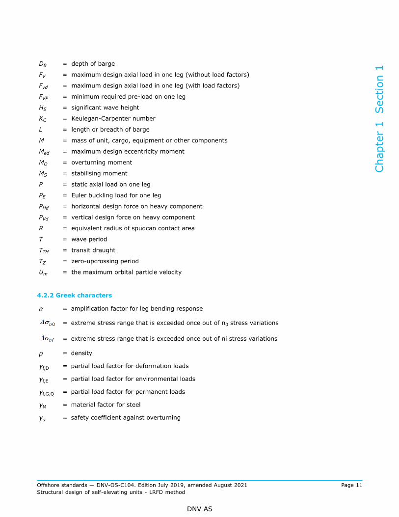
DB = depth of barge
FV = maximum design axial load in one leg (without load factors)
Fvd = maximum design axial load in one leg (with load factors)
FVP = minimum required pre-load on one leg
HS = significant wave height
KC = Keulegan-Carpenter number
L = length or breadth of barge
M = mass of unit, cargo, equipment or other components
Med = maximum design eccentricity moment
MO = overturning moment
MS = stabilising moment
P = static axial load on one leg
PE = Euler buckling load for one leg
PHd = horizontal design force on heavy component
PVd = vertical design force on heavy component
R = equivalent radius of spudcan contact area
T = wave period
TTH = transit draught
TZ = zero-upcrossing period
Um = the maximum orbital particle velocity
4.2.2 Greek characters
α = amplification factor for leg bending response
= extreme stress range that is exceeded once out of n0 stress variations
= extreme stress range that is exceeded once out of ni stress variations
ρ = density
γf,D = partial load factor for deformation loads
γf,E = partial load factor for environmental loads
γf,G,Q = partial load factor for permanent loads
γM = material factor for steel
γs = safety coefficient against overturning
Chapter 1 Section 1
Offshore standards — DNV-OS-C104. Edition July 2019, amended August 2021 Page 11Structural design of self-elevating units - LRFD method
DNV AS
CHAPTER 2 TECHNICAL CONTENT
SECTION 1 STRUCTURAL CATEGORISATION, MATERIAL SELECTIONAND INSPECTION PRINCIPLES
1 General
1.1 Scope
1.1.1 This section describes the structural categorisation, selection of steel materials and inspectionprinciples to be applied in design and construction of self-elevating units.
1.1.2 The structural application categories are determined based on the structural significance,consequences of failure and the complexity of the joints. The structural application categories set theselection of steel quality and the inspection extent of the welds.
1.1.3 The steel grades selected for structural components shall be related to calculated stresses andrequirements for toughness properties and shall be in compliance with the requirements given in DNV-OS-B101 and DNV-OS-C101.
2 Structural categorisationApplication categories for structural components are defined in DNV-OS-C101 Ch.2 Sec.3. Structuralmembers of self-elevating units are grouped as follows. Special category:
1) Vertical columns in way of intersection with the mat structure.2) Highly stressed elements at bottom leg connection to spudcan or mat.3) Intersections of lattice type leg structure that incorporates novel construction, including the use of steel
castings.4) Highly stressed elements of guide structures, jacking and locking system(s), jackhouse and support
structure.5) Highly stressed elements of crane pedestals and the support structure.
Guidance note:
Highly stressed elements are normally considered to be areas utilised more than 85% of the allowable yield capacity.
---e-n-d---o-f---g-u-i-d-a-n-c-e---n-o-t-e---
Primary category:
1) Combination of bulkhead, deck, side and bottom plating within the hull which forms «Box» or «I» typemain supporting structure.
2) All components of lattice type legs and external plating of cylindrical legs.3) Jackhouse supporting structure and bottom footing structure that receives initial transfer of load from
legs.4) Internal bulkheads, shell and deck of spudcan or bottom mat supporting structures which are designed
to distribute major loads, either uniform or concentrated, into the mat structure.
Chapter 2 Section 1
Offshore standards — DNV-OS-C104. Edition July 2019, amended August 2021 Page 12Structural design of self-elevating units - LRFD method
DNV AS

5) Main support structure of heavy substructures and equipment e.g. cranes, drill floor substructure,lifeboat platform and helicopter deck.
Guidance note:
Fatigue critical details within structural category primary are inspected according to requirements in category I as stated inDNV-OS-C101 Ch.2 Sec.3 [3.3].
---e-n-d---o-f---g-u-i-d-a-n-c-e---n-o-t-e---
Secondary category:
1) Deck, side and bottom plating of hull except areas where the structure is considered for primary orspecial application.
2) Bulkheads, stiffeners, decks and girders in hull that are not considered as primary or special application.3) Internal bulkheads and girders in cylindrical legs.4) Internal bulkheads, stiffeners and girders of spudcan or bottom mat supporting structures except where
the structures are considered primary or special application.
Guidance note:
Fatigue critical details within structural category secondary are inspected according to requirements in category I as stated inDNV-OS-C101 Ch.2 Sec.3 [3.3].
---e-n-d---o-f---g-u-i-d-a-n-c-e---n-o-t-e---
3 Material selection
3.1 General
3.1.1 Material specifications shall be established for all structural materials. Such materials shall be suitablefor their intended purpose and have adequate properties in all relevant design conditions. Material selectionshall be undertaken in accordance with the principles given in DNV-OS-C101.
3.1.2 When considering criteria appropriate to material grade selection, adequate consideration shall begiven to all relevant phases in the life cycle of the unit. In this connection there may be conditions andcriteria, other than those from the in-service, operational phase, that provide the design requirements inrespect to the selection of material. (Such criteria may, for example, be design temperature and/or stresslevels during marine operations.)
3.1.3 In special areas structural cross-joints essential for the overall structural integrity where high tensilestresses are acting perpendicular to the plane of the plate, the plate material shall be documented withproven through thickness properties, e.g. by utilising Z-quality steel.
3.1.4 Material designations are defined in DNV-OS-C101 Ch.2 Sec.3.
3.2 Design and service temperatures
3.2.1 The design temperature for a unit is the reference temperature for assessing areas where the unit maybe transported, installed and operated. The design temperature shall be lower or equal to the - lowest meandaily temperature in air for the relevant areas. For seasonal restricted operations the - lowest mean dailytemperature in air for the season may be applied.
Chapter 2 Section 1
Offshore standards — DNV-OS-C104. Edition July 2019, amended August 2021 Page 13Structural design of self-elevating units - LRFD method
DNV AS

3.2.2 The service temperatures for different parts of a unit apply for selection of structural steel. The servicetemperatures are defined as presented in [3.2.3] to [3.2.6]. In case different service temperatures aredefined in [3.2.3] to [3.2.6] for a structural part the lower specified value shall be applied.
3.2.3 External structures above the lowest astronomical tide (LAT) for the unit in elevated operation or abovethe light transit waterline during transportation shall not be designed for a service temperature higher thanthe design temperature for the unit.
3.2.4 External structures below the LAT during elevated operation and below the light transit waterlineduring transportation need not to be designed for service temperatures lower than 0°C.
3.2.5 Internal structures of mats, spudcans, legs and hull shall have the same service temperature as theadjacent external structure if not otherwise documented.
3.2.6 Internal structures in way of permanently heated rooms need not be designed for service temperatureslower than 0°C.
3.3 Selection of structural steel
3.3.1 The grade of steel to be used is in general to be related to the service temperature and thickness asshown in the tables in DNV-OS-C101 Ch.2 Sec.3 for the various application categories. Steel grades withspecified yield stress reduced for increased material thickness shall generally not be applied for structureswith special or primary category.
Guidance note:
The following steel grades are recommended:
- normal strength steel (NS): NV
- high strength steels (HS): NV 27S, NV 32, NV 36 and NV 40
- extra high strength steels (EHS): NV O420, NV O460, NV O500, NV O550, NV O620 and NV O690.
Steel grades specified with yield stress pending on thickness are not recommended used in self-elevating units and will beconsidered case by case.
---e-n-d---o-f---g-u-i-d-a-n-c-e---n-o-t-e---
3.3.2 For steel plates intended for racks and split tubes in rack and pinion jacking systems with servicetemperature down to -20°C, and where minimum yield stress equal to 690 N/mm2 is specified, grade NVEO690 may replace NV FO690 in the range 80 mm to 250 mm.The above also applies to steel plates/racks intended for legs of circular or polygonal shape, steel plates/racks in triangular chord sections and steel plates in primary area for jack-cases.
3.3.3 When post weld heat treatment is carried out in agreement with the yard, steel grades may beselected according to a higher service temperature than stipulated in DNV-OS-C101 Ch.2 Sec.3 Table 3.
Guidance note:
In such cases the thickness limitations in DNV-OS-C101 Ch.2 Sec.3 Table 3 may be selected one column left of the actual servicetemperature for the structure, i.e. for service temperatures 0°C, -10°C, -20°C, -25°C and -30°C the thickness limitation can be
based on ≥10°C, 0°C, -10°C, -20°C and -25°C, respectively.
---e-n-d---o-f---g-u-i-d-a-n-c-e---n-o-t-e---
3.3.4 For areas subjected to compressive and/or low tensile stresses, consideration may be given to the useof lower steel grades than stated in the tables of DNV-OS-C101 Ch.2 Sec.3.
Chapter 2 Section 1
Offshore standards — DNV-OS-C104. Edition July 2019, amended August 2021 Page 14Structural design of self-elevating units - LRFD method
DNV AS
3.3.5 The toughness requirements for steel plates, sections and weldments exceeding the thickness limits inthe table shall be evaluated in each separate case.
3.3.6 Grade of steel to be used for thicknesses less than 10 mm and/or design temperature above 0°Cshould be specially considered in each case.
3.3.7 Use of steels in anaerobic conditions or steels susceptible to hydrogen induced stress cracking (HISC)should be specially considered as specified in DNV-OS-C101 Ch.2 Sec.3.
4 Inspection categories
4.1 General
4.1.1 Welding and the extent of non-destructive examination during fabrication, shall be in accordance withthe requirements stipulated for the appropriate inspection category as defined in DNV-OS-C101.
4.1.2 Inspection categories determined in accordance with DNV-OS-C101 Ch.2 Sec.3 provide requirementsfor the minimum extent of required inspection.
Guidance note:
When considering the economic consequence that repair may entail, for example, in way of complex connections with limited ordifficult access, it may be considered prudent engineering practice to require more demanding requirements for inspection than therequired minimum.
---e-n-d---o-f---g-u-i-d-a-n-c-e---n-o-t-e---
4.1.3 When determining the extent of inspection, and the locations of required non-destructive testing NDT,in additional to evaluating design parameters (for example fatigue utilisation), consideration should be givento relevant fabrication parameters including:
— location of block or section joints— manual versus automatic welding— start and stop of weld etc.
Chapter 2 Section 1
Offshore standards — DNV-OS-C104. Edition July 2019, amended August 2021 Page 15Structural design of self-elevating units - LRFD method
DNV AS

SECTION 2 DESIGN PRINCIPLES
1 Introduction
1.1 General
1.1.1 The structure shall be designed according to the LRFD method with limit states and design conditionsas described in the present standard. A general description of the format of LRFD method is given in DNV-OS-C101.
1.1.2 Relevant load combinations shall be established for the various design conditions and limit states basedon the most unfavourable combinations of functional loads, environmental loads and/or accidental loads.
1.1.3 Modelling and analysis of the structure shall satisfactorily simulate the behaviour of the actualstructure, including its supporting system, and the relevant environmental conditions. Reasonablesimplifications may be introduced as a part of structural idealisation.
1.1.4 Limiting environmental and operating conditions (design data) for the different design conditions shallbe specified by the designer.
1.1.5 Requirements regarding certification of jacking gear machinery are given in DNV-OS-D101.
1.2 Overall design
1.2.1 The overall structural safety shall be evaluated on the basis of preventive measures against structuralfailure put into design, fabrication and in-service inspection as well as the unit's residual strength againsttotal collapse in the case of structural failure of vital elements.For vital elements, which are designed according to criteria given for intact structure, the likelihood andconsequence of failure should be considered as part of the redundancy evaluations. The consequence ofcredible accidental events shall be documented according to the accidental limit states (ALS), see Sec.6.
1.2.2 When determining the overall structural design, particular care shall be taken such that the solutiondoes not lead to unnecessarily complicated connections.
1.3 Details design
1.3.1 Structural connections should, in general, be designed with the aim to minimise stress concentrationsand reduce complex stress flow patterns. Connections should be designed with smooth transitions and properalignment of elements. Large cut-outs should be kept away from flanges and webs of primary girders inregions with high stresses.
1.3.2 Transmission of tensile stresses through the thickness of plates should be avoided as far as possible.In cases where transmission of tensile stresses through the thickness cannot be avoided, structural steel withimproved through thickness properties may be required, see Sec.1 [3].
1.3.3 Units intended for operations in cold areas shall be so arranged that water cannot be trapped in localstructures or machinery exposed to the ambient temperature.
Chapter 2 Section 2
Offshore standards — DNV-OS-C104. Edition July 2019, amended August 2021 Page 16Structural design of self-elevating units - LRFD method
DNV AS

1.3.4 If the unit is intended to be dry-docked the footing structure (i.e. mat or spudcans) shall be suitablystrengthened to withstand associated loads.
2 Design conditions
2.1 Basic conditionsThe following design conditions, as defined in Sec.1 [3], shall be considered as relevant for the unit:
— transit condition(s)— installation condition— operating condition(s)— survival condition— retrieval condition.
2.2 Transit
2.2.1 The present standard considers requirements for wet transits, i.e. field moves or ocean transits asdefined in Sec.1 [3]. Requirements in case of dry transit on a heavy lift vessel are considered to be coveredby the warranty authority for the operation.
2.2.2 A detailed assessment shall be undertaken for wet transits. The assessment shall include determinationof the limiting environmental criteria, evaluation of intact and damage stability characteristics, motionresponse, and possible wave freeboard exceedance. The occurrence of slamming loads on the structure andthe effects of fatigue during transport phases shall be evaluated when relevant.
Guidance note:
For guidance on global analysis for the transit condition see DNV-RP-C104 [4.5] and for environmental loading see DNV-RP-C205.The design criteria for wet transits are normally limited by aspects such as tug efficiency, green water on deck, sea fasteninglimitations and submergence of equipment extending outside the hull. As an example, towing operations of non-self propelled jack-ups are normally carried out in significant wave height less than five meters due to limitation of tug efficiency. For further guidancesee DNV-ST-N001 Marine operations and marine warranty.
---e-n-d---o-f---g-u-i-d-a-n-c-e---n-o-t-e---
2.2.3 The structure may be analysed for zero forward speed in analysis of wet transits.
2.2.4 The legs shall be designed for the static and inertia forces resulting from the motions in the mostsevere environmental transit conditions, combined with wind forces resulting from the maximum windvelocity.
2.2.5 The leg positions for both field moves and ocean moves shall be assessed when considering structuralstrength for transit condition.
2.2.6 In lieu of a more accurate analysis, for the ocean transit condition the legs shall be designed for thefollowing forces considered to act simultaneously:
— 100% of the acceleration forces from a 15° single amplitude roll or pitch at a 10 second period.— 120% of the static forces at the maximum amplitude of roll or pitch.
Chapter 2 Section 2
Offshore standards — DNV-OS-C104. Edition July 2019, amended August 2021 Page 17Structural design of self-elevating units - LRFD method
DNV AS

Guidance note:
These criteria define a reference design case for the ocean transit condition. As wind loads are not included, it is assumed thatloads/moments on the legs from gravity, wave and wind loads are not exceeding forces/moments caused by design values fromthe simplified motions above. Roll or pitch of 15° at 10 sec. is assumed to include the load effect from heave, sway and surgemotions.
---e-n-d---o-f---g-u-i-d-a-n-c-e---n-o-t-e---
A more accurate alternative is that the roll and pitch motions are determined by hydrodynamic calculation(motion analyses) or model test methods. The sea state(s) (Hs/Tz) used in determination for these motionsshall be specified in line with [1.1.4]. These motions shall be combined with a reference wind speed = 45 m/s in the check of leg strength, unless other wind speeds are specified by the designer. Wind velocity profileshall be taken according to DNV-RP-C104 [2.4].
2.2.7 For the field move position the legs may be designed for the acceleration forces caused by a 6° singleamplitude roll or pitch at the natural period of the unit plus 120% of the static forces at a 6° inclination of thelegs unless otherwise verified by model tests or calculations.
2.2.8 Dynamic amplification of the acceleration forces on the legs shall be accounted for if the naturalperiods of the legs are such that significant amplification may occur.
2.2.9 If considered relevant, the effect of vortex shedding induced vibrations of the legs due to wind shall betaken into account.
Guidance note:
For guidance relating to vortex induced oscillations see DNV-RP-C205 Sec.9.
---e-n-d---o-f---g-u-i-d-a-n-c-e---n-o-t-e---
2.2.10 The hull shall be designed for global mass and sea pressure loads, local loads and leg loads duringtransit.
2.2.11 Satisfactory compartmentation and stability during all floating operations shall be ensured, see DNV-OS-C301.
2.2.12 Unless satisfactory documentation exists demonstrating that shimming is not necessary, relevant leginterfaces (e.g. leg and upper guide) shall be shimmed in the transit condition.
2.2.13 All aspects of transportation, including planning and procedures, preparations, seafastenings andmarine operations should comply with the requirements of the warranty authority.
2.2.14 The structural strength of the hull, legs and footings during transit shall comply with the ultimatelimit states (ULS), fatigue limit states (FLS) and accidental limit state (ALS) given in Sec.4, Sec.5 and Sec.6,respectively.
2.3 Installation and retrieval
2.3.1 Relevant static and dynamic loads during installation and retrieval shall be accounted for in the design,including consideration of the maximum environmental conditions expected for the operations and leg impacton the seabed. In lieu of more accurate analysis the single amplitude for roll or pitch and period can bespecified by the designer, followed by a calculation according to DNV-RP-C104 [4.6] to derive the designcapacity for the leg. The design capacity for the leg shall be documented and may be presented as maximumleg force/moments for the leg at connection to the hull structure. Alternatively the design capacity may bepresented as horizontal and vertical point load at the spudcan tip for the relevant water depths.
Chapter 2 Section 2
Offshore standards — DNV-OS-C104. Edition July 2019, amended August 2021 Page 18Structural design of self-elevating units - LRFD method
DNV AS

Guidance note:
Guidance relating to simplified and conservative analytical methodology for bottom impact on the legs is given in DNV-RP-C104[4.6].
---e-n-d---o-f---g-u-i-d-a-n-c-e---n-o-t-e---
2.3.2 The preload capacity of the unit shall be defined, see Sec.7.
2.3.3 The hull structure shall be analysed to ensure it can withstand the maximum preload condition.
2.3.4 The structural strength of the hull, legs and footings during installation and retrieval shall comply withthe ULS given in Sec.4.
2.3.5 For tubular legs the guide system and legs shall be designed to resist torsional moment in the legs.The loads shall be specified by the designer.
Guidance note:
Torsional loads in the legs will typically occur during the installation and retrieval phases.
---e-n-d---o-f---g-u-i-d-a-n-c-e---n-o-t-e---
2.4 Operation and survival
2.4.1 The operation and survival conditions cover the unit in the hull elevated mode.
2.4.2 A detailed assessment shall be undertaken which includes determination of the limiting soils,environmental and mass criteria and the resulting, induced loads.
2.4.3 Dynamic structural deflection and stresses due to wave loading shall be accounted for if the naturalperiods of the unit are such that significant dynamic amplification may occur.
Guidance note:
It is not necessary to include dynamic amplification for the ULS checks (yield and buckling) when dynamic amplification factor(DAF) ≤ 1.10. DAF is described in DNV-RP-C104 [4.4], item (i).
---e-n-d---o-f---g-u-i-d-a-n-c-e---n-o-t-e---
2.4.4 Non-linear amplification (large displacement effects) of the overall deflections due to second orderbending effects of the legs shall be accounted for whenever significant.
2.4.5 The effect of leg fabrication tolerances and guiding system clearances shall be accounted for.
2.4.6 The leg/soil interaction shall be varied as necessary within the design specifications to providemaximum stress in the legs, both at the bottom end and at the jackhouse level.
2.4.7 Critical aspects to be considered in the elevated condition are structural strength, overturning stabilityand air gap.
2.4.8 The structural strength of the hull, legs and footings during operation and survival shall comply withthe ULS, FLS and ALS given in Sec.4, Sec.5 and Sec.6. The ULS assessment should be carried out for themost limiting conditions with the maximum storm condition and maximum operating condition examined as aminimum.
Chapter 2 Section 2
Offshore standards — DNV-OS-C104. Edition July 2019, amended August 2021 Page 19Structural design of self-elevating units - LRFD method
DNV AS

Guidance note:
The hull will typically comprise the following elements:
— decks
— sides and bottom plating
— longitudinal bulkheads
— transverse bulkheads and frames
— longitudinal girders and stringers
— stringers and web frames on the transverse bulkheads
— jackhouses.
---e-n-d---o-f---g-u-i-d-a-n-c-e---n-o-t-e---
2.4.9 The strength of the hull shall be assessed based on the characteristic load conditions that result inmaximum longitudinal tension and compression stresses (for yield and buckling assessment) in deck andbottom plating.
2.4.10 The effect of large openings in the hull (e.g. drill slot) that affect the distribution of global stressesshould be determined by a finite element model accounting for three dimensional effects.
3 Environmental loads
3.1 General
3.1.1 Environmental loads are loads which may vary in magnitude, position and direction during the periodunder consideration, and which are related to operations and normal use of the installation. Examples are:
— hydrodynamic loads induced by waves and current— inertia forces— wind— tidal effects— marine growth— snow and ice.
Guidance note:
Earthquake assessments are considered scope of site specific assessments, unless agreed otherwise. For guidance fordetermination of risk of earthquake actions and analysis procedures, see ISO 19905-1, ISO19901-2 and NORSOK N-003.
---e-n-d---o-f---g-u-i-d-a-n-c-e---n-o-t-e---
3.1.2 The specified environmental design data used for calculating design loads for intact structure shallcorrespond with the most probable largest values for a return period of 100 years, see DNV-OS-C101.
3.1.3 For damaged structure calculations a return period of one year shall be used, see DNV-OS-C101.
3.1.4 The environmental design data may be given as maximum wave heights with corresponding periodsand wind- and current velocities and design temperatures or as acceptable geographical areas for operation.In the latter case the designer shall specify the operational areas and submit documentation showing that theenvironmental data for these areas are within the environmental design data.
3.1.5 The statistical data used as a basis for design shall cover a sufficiently long period of time.
Chapter 2 Section 2
Offshore standards — DNV-OS-C104. Edition July 2019, amended August 2021 Page 20Structural design of self-elevating units - LRFD method
DNV AS
3.2 Wind
3.2.1 Wind velocity statistics shall be used as a basis for a description of wind conditions, if such data areavailable. Sustained, gust, and one hour wind are defined in Ch.1 Sec.1 [3].
3.2.2 Characteristic wind design velocities shall be based upon appropriate considerations of velocity andheight profiles for the relevant averaging time.
Guidance note:
Practical information with respect to wind conditions, including velocity and height profiles, is documented in DNV-RP-C205 andDNV-RP-C104 [2.4] and DNV-RP-C104 [3.4]. The wind service restrictions should be specified by the designer. Unrestrictedworldwide operation is not applicable for self-elevating units. However, a wind velocity vR of not less than 51.5 m/s combined withmaximum wave forces will cover most offshore locations. vR = refers to 1 minute wind speed at a height 10m above the still waterlevel. The corresponding wind force should be based on a wind velocity profile given by DNV-RP-C205 [2.3.2.11], or equivalent.See also the guidance given in DNV-RP-C104 [3.4] and DNV-RP-C104 [3.4].
---e-n-d---o-f---g-u-i-d-a-n-c-e---n-o-t-e---
3.2.3 When wind tunnel data obtained from reliable and adequate tests on a representative model of the unitare available, these data will be considered for the determination of pressures and resulting forces.
3.3 Waves
3.3.1 Wave conditions which shall be considered for design purposes may be described either bydeterministic (regular) design wave methods or by stochastic (irregular seastate) methods applying waveenergy spectra.
3.3.2 Short term irregular seastates are described by means of wave energy spectra that are characterisedby significant wave height (HS), and average zero-upcrossing period (TZ). Analytical spectrum expressionsshall reflect the width and shape of typical spectra for the considered height. The shortcrestedness of wavesin a seaway, i.e. the directional dispersion of wave energy, may be taken into account. The principal directionof wave encounter is defined as the direction of maximum wave energy density.
Guidance note:
For open sea locations the Pierson-Moskowitz (P-M) type of spectrum may be applied. For shallow water, or locations with a narrowfetch, a narrower spectrum should be considered (e.g. Jonswap spectrum). Practical information in respect to wave conditions isdocumented in DNV-RP-C205 Sec.3 and DNV-RP-C104 [2.2].
---e-n-d---o-f---g-u-i-d-a-n-c-e---n-o-t-e---
3.3.3 The long term behaviour of the sea is described by means of a family of wave spectra, the probabilityof occurrence for each spectrum being taken into account.
3.3.4 For this purpose one needs the joint probability density function for HS and TZ, which may be obtainedfrom wave statistics. A description of the long term seastates based on the use of hindcastings may alsobe accepted. Wave statistics for individual principal directions of wave encounter should be used, otherwiseconservative assumptions shall be introduced.Extreme wave heights are expressed in terms of wave heights having a low probability of occurrence.The N year wave height is the most probable largest individual wave height during N years. This is equivalentto a wave height with a return period of N years.
Chapter 2 Section 2
Offshore standards — DNV-OS-C104. Edition July 2019, amended August 2021 Page 21Structural design of self-elevating units - LRFD method
DNV AS

3.3.5 In deterministic design procedures, based on regular wave considerations, the wave shall be describedby the following parameters:
— wave period— wave height— wave direction— still-water depth.
The choice of an appropriate design wave formulation has to be based on particular considerations for theproblem in question. Shallow water effects shall be accounted for.
3.3.6 The design waves shall be those that produce the most unfavourable loads on the consideredstructure, taking into account the shape and size of structure, etc.The wave period shall be specified in each case of application. It may be necessary to investigate arepresentative number of wave periods, in order to ensure a sufficiently accurate determination of themaximum loads.
3.4 Current
3.4.1 Adequate current velocity data shall be selected from the statistics available. Different components ofcurrent shall be considered, such as tidal current and wind generated current.
3.4.2 The variation of current velocity over the water depth shall be considered when this is relevant.
3.5 TemperatureThe design temperature shall be specified as necessary for the areas where the unit is planned to operate orbe transported, see Sec.1 [3.2].
3.6 Snow and iceSnow and ice shall be considered as necessary for the areas where the unit is planned to operate or betransported.
4 Method of analysis
4.1 General
4.1.1 Structural analysis shall be performed to evaluate the structural strength due to global and localeffects.
4.1.2 The following responses shall be considered in the structural design whenever significant:
— dynamic stresses for all limit states— non-linear wave loading effects (e.g. effect of drag and finite wave elevation)— non-linear amplification due to second order bending effects of the legs (P-delta effect)— effects of leg fabrication tolerances and leg guiding system clearances— slamming induced vibrations— vortex induced vibrations (e.g. resulting from wind loads on structural elements in a flare tower or inlattice legs above jackhouses)
— friction and wear (e.g. at leg guiding system or at riser system interfaces with hull structures).
Chapter 2 Section 2
Offshore standards — DNV-OS-C104. Edition July 2019, amended August 2021 Page 22Structural design of self-elevating units - LRFD method
DNV AS
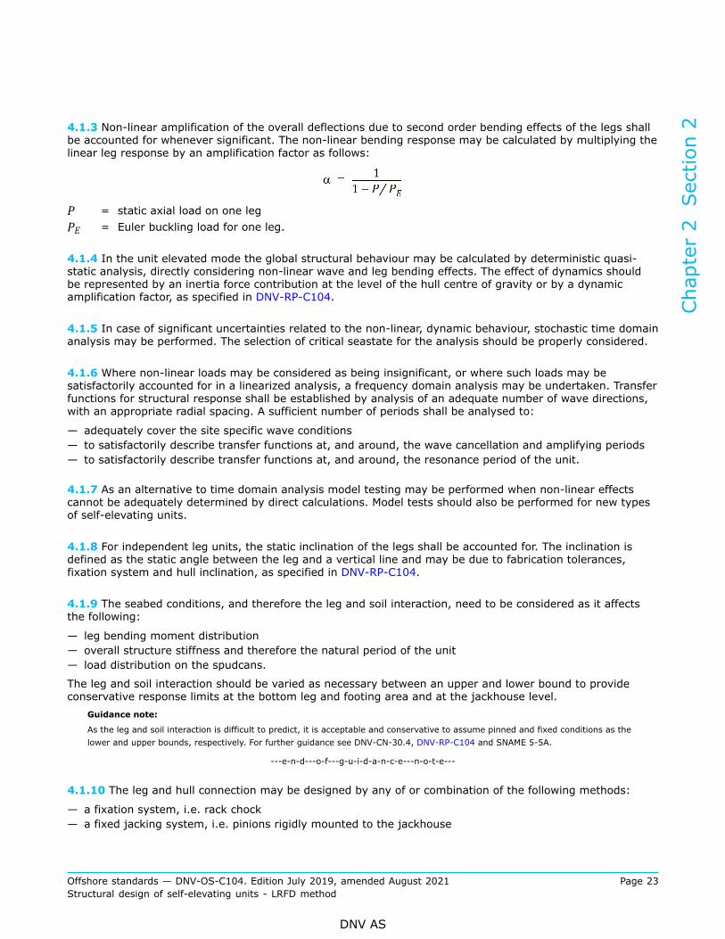
4.1.3 Non-linear amplification of the overall deflections due to second order bending effects of the legs shallbe accounted for whenever significant. The non-linear bending response may be calculated by multiplying thelinear leg response by an amplification factor as follows:
P = static axial load on one legPE = Euler buckling load for one leg.
4.1.4 In the unit elevated mode the global structural behaviour may be calculated by deterministic quasi-static analysis, directly considering non-linear wave and leg bending effects. The effect of dynamics shouldbe represented by an inertia force contribution at the level of the hull centre of gravity or by a dynamicamplification factor, as specified in DNV-RP-C104.
4.1.5 In case of significant uncertainties related to the non-linear, dynamic behaviour, stochastic time domainanalysis may be performed. The selection of critical seastate for the analysis should be properly considered.
4.1.6 Where non-linear loads may be considered as being insignificant, or where such loads may besatisfactorily accounted for in a linearized analysis, a frequency domain analysis may be undertaken. Transferfunctions for structural response shall be established by analysis of an adequate number of wave directions,with an appropriate radial spacing. A sufficient number of periods shall be analysed to:
— adequately cover the site specific wave conditions— to satisfactorily describe transfer functions at, and around, the wave cancellation and amplifying periods— to satisfactorily describe transfer functions at, and around, the resonance period of the unit.
4.1.7 As an alternative to time domain analysis model testing may be performed when non-linear effectscannot be adequately determined by direct calculations. Model tests should also be performed for new typesof self-elevating units.
4.1.8 For independent leg units, the static inclination of the legs shall be accounted for. The inclination isdefined as the static angle between the leg and a vertical line and may be due to fabrication tolerances,fixation system and hull inclination, as specified in DNV-RP-C104.
4.1.9 The seabed conditions, and therefore the leg and soil interaction, need to be considered as it affectsthe following:
— leg bending moment distribution— overall structure stiffness and therefore the natural period of the unit— load distribution on the spudcans.
The leg and soil interaction should be varied as necessary between an upper and lower bound to provideconservative response limits at the bottom leg and footing area and at the jackhouse level.
Guidance note:
As the leg and soil interaction is difficult to predict, it is acceptable and conservative to assume pinned and fixed conditions as thelower and upper bounds, respectively. For further guidance see DNV-CN-30.4, DNV-RP-C104 and SNAME 5-5A.
---e-n-d---o-f---g-u-i-d-a-n-c-e---n-o-t-e---
4.1.10 The leg and hull connection may be designed by any of or combination of the following methods:
— a fixation system, i.e. rack chock— a fixed jacking system, i.e. pinions rigidly mounted to the jackhouse
Chapter 2 Section 2
Offshore standards — DNV-OS-C104. Edition July 2019, amended August 2021 Page 23Structural design of self-elevating units - LRFD method
DNV AS
— a floating jacking system, i.e. pinions mounted to the jackhouse by means of flexible shock pads— a guiding system by upper and lower guides.
The characteristics and behaviour of the actual leg and hull connection system need to be properlyrepresented in the appropriate global and local analyses.
Guidance note:
Practical information in respect to modelling leg and hull interaction is documented in DNV-RP-C104 [4.3] or SNAME 5-5A, Section5.6.
---e-n-d---o-f---g-u-i-d-a-n-c-e---n-o-t-e---
4.2 Global structural models
4.2.1 A global structural model shall represent the global stiffness and behaviour of the unit. The globalmodel should usually represent the following:
— footing main plating and stiffeners— leg truss or shell and stiffeners— jackhouse and leg/hull interaction— main bulkheads, frameworks and decks for the deck structure (secondary decks which are not taking partin the global structural capacity need not be modelled)
— mass model.
4.2.2 Depending on the purpose of the analysis and possible combination with further local analysis thedifferent level of idealisation and detailing may be applied for a global structure. The hull may either berepresented by a detailed plate and shell model or a model using grillage beams. The legs may be modelledby detailed structural models or equivalent beams, or a combination of such.
Guidance note:
For further guidance regarding modelling procedures see DNV-RP-C104 or SNAME 5-5A.
---e-n-d---o-f---g-u-i-d-a-n-c-e---n-o-t-e---
4.3 Local structural models
4.3.1 An adequate number of local structural models should be created in order to evaluate response ofthe structure to variations in local loads. The model(s) should be sufficiently detailed such that resultingresponses are obtained to the required degree of accuracy. A number of local models may be required inorder to fully evaluate local response at all relevant sections.The following local models should be analysed in the evaluation of ULS:
— footing, mat or spudcan. Including the lower part of the leg (typically at least 2 bays)— stiffened plates subjected to tank pressures or deck area loads— leg and hull connection system including jackhouse support structure— support structure for heavy equipment such as drill floor and pipe racks— riser hang off structure— crane pedestal support structure— helicopter deck support structure.
4.3.2 A detailed finite element model should be applied to calculate the transfer of leg axial forces, bendingmoments and shears between the upper and lower guide structures and the jacking and/or fixation system.The systems and interactions should be properly modelled in terms of stiffness, orientation and clearances.The analysis model should include a detailed model of the leg in the hull interface area, the guides, fixationand/or jacking system, together with the main jackhouse structure.
Chapter 2 Section 2
Offshore standards — DNV-OS-C104. Edition July 2019, amended August 2021 Page 24Structural design of self-elevating units - LRFD method
DNV AS
Guidance note:
The detailed leg model should normally extend 4 bays below and above the lower and upper guides, respectively. For furtherguidance regarding modelling procedures see DNV-RP-C104 or SNAME 5-5A.
---e-n-d---o-f---g-u-i-d-a-n-c-e---n-o-t-e---
4.4 Fatigue analysis
4.4.1 The design fatigue life shall be calculated considering the combined effects of global and localstructural response. The expected dynamic load history shall be specified in the design brief as basis for thecalculations.
4.4.2 Stress concentration factors for fatigue sensitive structural details that cannot be obtained fromstandard tables, e.g. due to different structural arrangement or that dimensions are out of range of theformula, shall be determined by a finite element analysis. C
hapter 2 Section 2
Offshore standards — DNV-OS-C104. Edition July 2019, amended August 2021 Page 25Structural design of self-elevating units - LRFD method
DNV AS

SECTION 3 DESIGN LOADS
1 Introduction
1.1 General
1.1.1 The requirements in this section define and specify load components and load combinations to beconsidered in the overall strength analysis as well as design pressures applicable in formulae for localscantlings.
1.1.2 Characteristic loads shall be used as reference loads. General description of load components andcombinations are given in DNV-OS-C101. Details regarding environmental loads are described in DNV-RP-C205 and DNV-RP-C104 Sec.2 and DNV-RP-C104 [3.4]. Presentation of load categories relevant for self-elevating units is given in [2] to [8].
2 Permanent loadsPermanent loads are loads that will not vary in magnitude, position, or direction during the period consideredand include:
— lightweight of the unit, including mass of permanently installed modules and equipment, such asaccommodation, helicopter deck, drilling and production equipment
— permanent ballast— hydrostatic pressures resulting from buoyancy— pretension in respect to drilling and production systems (e.g. risers, etc.).
3 Variable functional loads
3.1 General
3.1.1 Variable functional loads are loads that may vary in magnitude, position and direction during the periodunder consideration.
3.1.2 Except where analytical procedures or design specifications otherwise require, the value of the variableloads utilised in structural design should be taken as either the lower or upper design value, whichever givesthe more unfavourable effect. Variable functional loads on deck areas may be found in DNV-OS-C101 Ch.2Sec.2. These should be applied unless specified otherwise in deck load plans, design basis or design brief.
3.1.3 Variations in operational mass distributions (including variations in tank load conditions) shall beadequately accounted for in the structural design.
3.1.4 Design criteria resulting from operational requirements should be fully considered. Examples of suchoperations may be:
— drilling, production, workover, and combinations thereof— consumable re-supply procedures— maintenance procedures— possible mass re-distributions in extreme conditions.
3.1.5 Dynamic loads resulting from flow through air pipes during filling operations shall be adequatelyconsidered in the design of tank structures.
Chapter 2 Section 3
Offshore standards — DNV-OS-C104. Edition July 2019, amended August 2021 Page 26Structural design of self-elevating units - LRFD method
DNV AS

3.2 Tank loads
3.2.1 Variations in tank loading conditions, including empty tanks, shall be adequately accounted for in thestructural design.
3.2.2 A minimum design density (ρ) of 1.025 t/m3 should be considered in the determination of theappropriate scantlings of tank arrangements.
3.2.3 The extent to which it is possible to fill sounding, venting or loading pipe arrangements shall be fullyaccounted for in determination of the maximum design pressure which a tank may be subjected to.
3.2.4 Dynamic pressure heads resulting from the filling of such pipes shall be included in the design pressurehead where such load components are applicable.
3.2.5 All tanks shall be designed for the following internal design pressure:
(kN/m2)
where:hop = vertical distance (m) from the load point to the position of maximum filling height.
For tanks adjacent to the sea and situated below the extreme operational draught (TE) during wettransit, hop should not be taken less than the distance from the load point to the static sea level.
av = maximum vertical acceleration, (m/s2), being the coupled motion response applicable to the tank inquestion.The vertical acceleration term only applies to transit conditions. For conditions with the deckelevated av may be taken equal to zero.
γf,G,Q = partial load factor for permanent and functional loading, see Sec.4 Table 1.γf,E = partial load factor for environmental loads, see Sec.4 Table 1. Descriptions and requirements related to different tank arrangements are given in DNV-OS-D101 Ch.2 Sec.3[3.3].A special tank filling design condition shall be checked according to ULS loading combination a) for tankswhere the air-pipe may be filled during filling operations. The following additional internal design pressureconditions shall be used:
(kN/m2)
where:pdyn = pressure (kN/m2) due to flow through pipes, minimum 25 kN/m2
Guidance note:
This internal pressure need not to be combined with extreme environmental loads. Normally only static global response need to beconsidered.
---e-n-d---o-f---g-u-i-d-a-n-c-e---n-o-t-e---
3.2.6 Requirements for testing of tank tightness and structural strength are given in DNV-OS-C401 Ch.2Sec.8.
Chapter 2 Section 3
Offshore standards — DNV-OS-C104. Edition July 2019, amended August 2021 Page 27Structural design of self-elevating units - LRFD method
DNV AS

4 Environmental loads
4.1 General
4.1.1 General considerations for environmental loads are given in DNV-OS-C101 Ch.2 Sec.2 [5] and DNV-OS-C101 Ch.2 Sec.2 [6], in DNV-RP-C205 and in DNV-RP-C104.
4.1.2 Combinations of environmental loads are stated in DNV-OS-C101 Ch.2 Sec.2 Table 4.
4.2 Wind loads
4.2.1 In conjunction with maximum wave forces the sustained wind velocity, i.e. the 1 minute averagevelocity, shall be used. If gust wind alone is more unfavourable than sustained wind in conjunction with waveforces, the gust wind velocity shall be used. For local load calculations gust wind velocity shall be used.
4.2.2 Formulas for calculation of wind loads may be taken from DNV-RP-C205 Sec.5. See also the guidancegiven in DNV-RP-C104 [2.4] and DNV-RP-C104 [3.4].
4.2.3 Applicable shape coefficients for different structure parts are given in Table 1. For shapes orcombination of shapes which do not readily fall into the categories in Table 1 the formulas in DNV-RP-C205Sec.5 should be applied.
Table 1 Shape coefficient
Type of structure or member Cs
Hull, based on total projected area 1.0
Deckhouses, jack-frame structure, sub-structure, draw-works house, and other above deck blocks, based on totalprojected area of the structure.
1.1
Leg sections projecting above the jack-frame and below thehull See DNV-RP-C205
Isolated tubulars, (e.g. crane pedestals, etc.) 0.5
Isolated structural shapes, (e.g. angles, channels, boxes,
I-sections), based on member projected area1.5
Derricks, crane booms, flare towers (open lattice sectionsonly, not boxed-in sections)
According to DNV-RP-C205 or by use of theappropriate shape coefficient for the members
concerned applied to 50% of the total projected area.
4.2.4 For local design the pressure acting on vertical external bulkheads exposed to wind shall in general notbe taken less than 2.5 kN/m2.
4.2.5 For structures being sensitive to dynamic loads, for instance tall structures having long naturalperiod of vibration, the stresses due to the gust wind pressure considered as static shall be multiplied by anappropriate dynamic amplification factor.
Chapter 2 Section 3
Offshore standards — DNV-OS-C104. Edition July 2019, amended August 2021 Page 28Structural design of self-elevating units - LRFD method
DNV AS
4.2.6 The possibility of vibrations due to instability in the flow pattern induced by the structure itself shouldalso be considered.
4.3 Waves
4.3.1 The basic wave load parameters and response calculation methods in this standard shall be used in awave load analysis where the most unfavourable combinations of height, period and direction of the wavesare considered.
4.3.2 The liquid particle velocity and acceleration in regular waves shall be calculated according torecognised wave theories, taking into account the significance of shallow water and surface elevation.Linearized wave theories may be used when appropriate. In such cases appropriate account shall be taken ofthe extrapolation of wave kinematics to the free surface.
4.3.3 The wave design data shall represent the maximum wave heights specified for the unit, as well as themaximum wave steepness according to the unit design basis. The wave lengths shall be selected as the mostcritical ones for the response of the structure or structural part to be investigated.
Guidance note:
Practical information in respect to wave conditions, including wave steepness criteria and wave stretching, is documented in DNV-RP-C205 Sec.3. See also DNV-RP-C104 [2.2] and DNV-RP-C104 [2.3].
---e-n-d---o-f---g-u-i-d-a-n-c-e---n-o-t-e---
4.3.4 For a deterministic wave analysis using an appropriate non-linear wave theory for the water depth,i.e. Stokes' 5th or Dean's Stream Function, the fluid velocity of the maximum long-crested 100 year wavemay be multiplied with a kinematic reduction factor of 0.86. The scaling of the velocity shall be used only inconnection with hydrodynamic coefficients defined according to [4.5.3], i.e. CD ≥ 1.0 for submerged tubularmembers of self-elevating units.
Guidance note:
The kinematics reduction factor is introduced to account for the conservatism of deterministic, regular wave kinematicstraditionally accomplished by adjusting the hydrodynamic properties.
---e-n-d---o-f---g-u-i-d-a-n-c-e---n-o-t-e---
4.4 CurrentCharacteristic current design velocities shall be based upon appropriate consideration of velocity andheight profiles. The variation in current profile with variation in water depth, due to wave action shall beappropriately accounted for.
Guidance note:
Practical information in respect to current conditions, including current stretching in the passage of a wave, is documented in DNV-RP-C205 Sec.4 and DNV-RP-C104 [2.3] and DNV-RP-C104 [3.4].
---e-n-d---o-f---g-u-i-d-a-n-c-e---n-o-t-e---
4.5 Wave and current loads
4.5.1 Wave and current loads should be calculated using Morison’s equation.Guidance note:
For information regarding use of Morison’s equation see DNV-RP-C205 Sec.6 and DNV-RP-C104 [3.4].
---e-n-d---o-f---g-u-i-d-a-n-c-e---n-o-t-e---
Chapter 2 Section 3
Offshore standards — DNV-OS-C104. Edition July 2019, amended August 2021 Page 29Structural design of self-elevating units - LRFD method
DNV AS

4.5.2 Vector addition of the wave and current induced particle velocities should be used for calculation ofthe combined wave and current drag force. If available, computations of the total particle velocities andacceleration based on more exact theories of wave and current interaction may be preferred.
4.5.3 Hydrodynamic coefficients for circular cylinder in oscillatory flow with in-service marine roughness, andfor high values of the Keulegan-Carpenter number, i.e. KC > 37, may be taken as given in Table 2.
Table 2 Hydrodynamic coefficients
Surface condition Drag coefficient, CD (k/D) Inertia coefficient, CM (k/D)
Multiyear roughness k/D > 1/100 1.05 1.8
Mobile unit (cleaned) k/D < 1/100 1.0 1.8
Smooth member k/D < 1/10000 0.65 2.0
The Keulegan-Carpenter number is defined by:
k = the roughness height
D = the member diameter
Um = the maximum orbital particle velocity
T = the wave period
More detailed formulations for CD of tubular members depending on surface condition and Keulegan-Carpenternumber can be found in DNV-RP-C205 Sec.6.
4.5.4 The roughness for a mobile unit (cleaned) applies when marine growth roughness is removed betweensubmersions of members.
4.5.5 The smooth values may apply above MWL + 2 m and the rough values below MWL + 2 m, where MWLis the mean still water level, as defined in DNV-RP-C205 Figure 4-2.
4.5.6 The above hydrodynamic coefficients apply both for deterministic wave analyses when the guidancegiven in [4.3.4] is followed and for stochastic wave analysis.
4.5.7 Assumptions regarding allowable marine growth shall be stated in the basis of design.
4.5.8 For non-tubular members the hydrodynamic coefficients should reflect the actual shape of the crosssections and member orientation relative to the wave direction.
Guidance note:
Hydrodynamic coefficients relevant to typical self-elevating unit chord designs are stated in DNV-RP-C205 Sec.6. See also SNAME5-5A. Equivalent single beam hydrodynamic parameters for lattice-type legs may be obtained fromDNV-RP-C104 [A.6].
---e-n-d---o-f---g-u-i-d-a-n-c-e---n-o-t-e---
4.6 Sea pressures during transit
4.6.1 Unless otherwise documented the characteristic sea pressure acting on the bottom, side and externaldecks of a self-elevating unit in transit condition should be taken as:
Chapter 2 Section 3
Offshore standards — DNV-OS-C104. Edition July 2019, amended August 2021 Page 30Structural design of self-elevating units - LRFD method
DNV AS

where the static pressure is:
(kN/m2) for zb ≤ TTH
(kN/m2) for zb > TTH
The dynamic pressure for hull sides and bottom is:
(kN/m2) for zb ≤ TTH
(kN/m2) for zb > TTH
The dynamic pressure for external decks and superstructure bulkheads is:
(kN/m2)
where:TTH = heavy transit draught (m) measured vertically from the moulded baseline to the uppermost transit
waterlinezb = vertical distance from the moulded baseline to the load point (m)DB = depth of barge (m)L = greater of unit length or breadth (m)ρ = density (T/m3)χ =
Cw =
Ce = 1.0 for exposed structure= 0.5 for sheltered structure
Y = shortest horizontal distance from side shell to load point (m)zd = vertical distance from main deck to centre of tier (m).
Guidance note:
The pressure coefficient Ce for decks may be selected as for sheltered structure. Structure should in general be defined as exposedunless proven otherwise by model tests, CFD calculations, or simplified assessments of green water behaviour on deck.
---e-n-d---o-f---g-u-i-d-a-n-c-e---n-o-t-e---
4.6.2 Model tests or validated calculations may be applied to establish alternative design pressures toaccount for green sea loading on decks, superstructures and deckhouses, see Sec.4 [2.6].
4.6.3 The dynamic pressure for superstructures and deckhouses is valid for units designed for wet transitwith a limitation of significant wave height less or equal to five meters, see also Sec.2 [2.2.2].
4.7 Heavy components during transitThe forces acting on supporting structures and lashing systems for rigid units of cargo, equipment or otherstructural components should be taken as:
(kN)
(kN)
Chapter 2 Section 3
Offshore standards — DNV-OS-C104. Edition July 2019, amended August 2021 Page 31Structural design of self-elevating units - LRFD method
DNV AS

where:av = vertical acceleration (m/s2)ah = horizontal acceleration (m/s2)M = mass of cargo, equipment or other components (ton)PVd = vertical design forcePHd = horizontal design force.For units exposed to wind, a horizontal force due to the design gust wind shall be added to PHd.
Guidance note:
For self-elevating units in transit condition, αh and αv need not be taken larger than 0.5 g0 (m/s2). PHd is applied at the verticalposition of the load resultant(s) to account for the vertical force couple introduced at the foundations of the heavy equipment.
---e-n-d---o-f---g-u-i-d-a-n-c-e---n-o-t-e---
5 Deformation loads
5.1 GeneralDeformation loads caused by inflicted deformations, such as temperature loads, built-in deformations, etc.should be considered as appropriate. Further details and description of deformation loads are given in DNV-OS-C101 Ch.2 Sec.2 [8].
5.2 Displacement dependent loadsLoad effects that are a consequence of the displacement of the unit in the elevated condition shall beaccounted for. Such effects are due to the first order sway (P-delta), and its enhancement due to theincreased flexibility of the legs in the presence of axial loads, i.e. Euler amplification.
Guidance note:
Simplified method to include the P-Δ effect is given in DNV-RP-C104 [4.4.8].
---e-n-d---o-f---g-u-i-d-a-n-c-e---n-o-t-e---
6 Accidental loads
6.1 General
6.1.1 Accidental loads are loads related to abnormal operations or technical failure. Relevant accidentalevents are given in Sec.6.
6.1.2 Relevant accidental loads should be determined on the basis of an assessment and relevantexperience. Guidance regarding implementation, use and updating of such assessments and genericaccidental loads, see DNV-OS-A101.
6.1.3 For temporary design conditions, the characteristic load may be a specified value dependent onpractical requirements. The level of safety related to the temporary design conditions is not to be inferior tothe safety level required for the operating design conditions.
Chapter 2 Section 3
Offshore standards — DNV-OS-C104. Edition July 2019, amended August 2021 Page 32Structural design of self-elevating units - LRFD method
DNV AS

7 Fatigue loads
7.1 General
7.1.1 Repetitive loads, which may lead to possible significant fatigue damage, shall be evaluated. Thefollowing listed sources of fatigue loads shall, where relevant, be considered:
— waves (including loads caused by slamming and variable (dynamic) pressures)— wind (especially when vortex induced vibrations may occur)— currents (especially when vortex induced vibrations may occur)— mechanical vibration (e.g. caused by operation of machinery)— mechanical loading and unloading (e.g. due to jacking or crane operations).
The effects of both local and global dynamic response shall be properly accounted for when determiningresponse distributions related to fatigue loads.
7.1.2 Further considerations with respect to fatigue loads are given in DNV-RP-C203.
8 Combination of loads
8.1 General
8.1.1 Load combinations for the design limit states are, in general given in DNV-OS-C101 Ch.2 Sec.2.Specific load factors for self-elevating units for the ULS are given in Sec.4.
8.1.2 Structural strength shall be evaluated considering all relevant, realistic load conditions andcombinations. Scantlings shall be determined on the basis of criteria that combine, in a rational manner, theeffects of relevant global and local responses for each individual structural element.
8.1.3 A sufficient number of load conditions shall be evaluated to ensure that the characteristic largest (orsmallest) response, for the appropriate return period, has been established.
Guidance note:
For example, maximum global, characteristic responses for a self-elevating unit may occur in environmental conditions that are notassociated with the characteristic, largest, wave height. In such cases, wave period and associated wave steepness parameters aremore likely to be governing factors in the determination of maximum and minimum responses.
---e-n-d---o-f---g-u-i-d-a-n-c-e---n-o-t-e---
Chapter 2 Section 3
Offshore standards — DNV-OS-C104. Edition July 2019, amended August 2021 Page 33Structural design of self-elevating units - LRFD method
DNV AS
SECTION 4 ULTIMATE LIMIT STATES
1 General
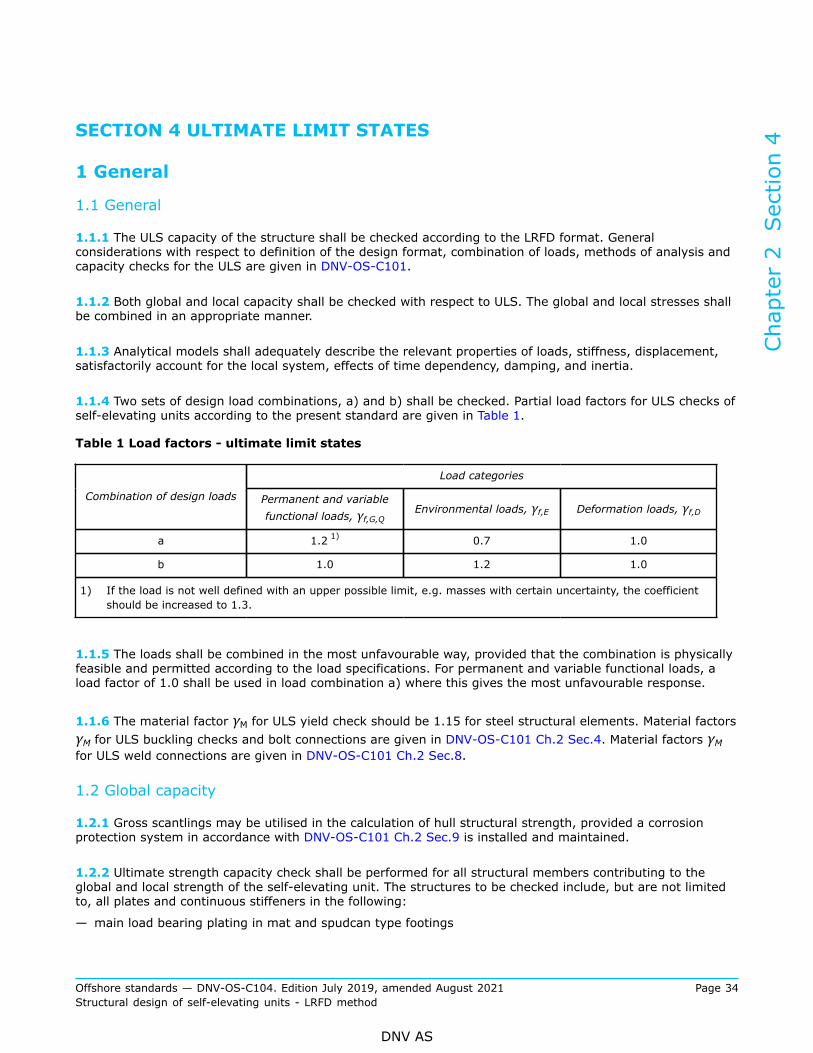
1.1 General
1.1.1 The ULS capacity of the structure shall be checked according to the LRFD format. Generalconsiderations with respect to definition of the design format, combination of loads, methods of analysis andcapacity checks for the ULS are given in DNV-OS-C101.
1.1.2 Both global and local capacity shall be checked with respect to ULS. The global and local stresses shallbe combined in an appropriate manner.
1.1.3 Analytical models shall adequately describe the relevant properties of loads, stiffness, displacement,satisfactorily account for the local system, effects of time dependency, damping, and inertia.
1.1.4 Two sets of design load combinations, a) and b) shall be checked. Partial load factors for ULS checks ofself-elevating units according to the present standard are given in Table 1.
Table 1 Load factors - ultimate limit states
Load categories
Combination of design loads Permanent and variablefunctional loads, γf,G,Q
Environmental loads, γf,E Deformation loads, γf,D
a 1.2 1) 0.7 1.0
b 1.0 1.2 1.0
1) If the load is not well defined with an upper possible limit, e.g. masses with certain uncertainty, the coefficientshould be increased to 1.3.
1.1.5 The loads shall be combined in the most unfavourable way, provided that the combination is physicallyfeasible and permitted according to the load specifications. For permanent and variable functional loads, aload factor of 1.0 shall be used in load combination a) where this gives the most unfavourable response.
1.1.6 The material factor γM for ULS yield check should be 1.15 for steel structural elements. Material factorsγM for ULS buckling checks and bolt connections are given in DNV-OS-C101 Ch.2 Sec.4. Material factors γMfor ULS weld connections are given in DNV-OS-C101 Ch.2 Sec.8.
1.2 Global capacity
1.2.1 Gross scantlings may be utilised in the calculation of hull structural strength, provided a corrosionprotection system in accordance with DNV-OS-C101 Ch.2 Sec.9 is installed and maintained.
1.2.2 Ultimate strength capacity check shall be performed for all structural members contributing to theglobal and local strength of the self-elevating unit. The structures to be checked include, but are not limitedto, all plates and continuous stiffeners in the following:
— main load bearing plating in mat and spudcan type footings
Chapter 2 Section 4
Offshore standards — DNV-OS-C104. Edition July 2019, amended August 2021 Page 34Structural design of self-elevating units - LRFD method
DNV AS

— all leg members in truss type legs— outer plating in column type legs— jackhouse and supporting structure— main load-bearing bulkheads, frameworks and decks in the hull structure— girders in the hull structure.
2 Structural capacity
2.1 General
2.1.1 Design principles for strength analysis are given in DNV-OS-C101 Ch.2 Sec.4 and DNV-RP-C104.
2.1.2 Structural members shall be checked for the most unfavourable combinations of loadings. Girders,pillars, bulkheads, decks and other plate panels shall be checked for relevant combinations of global andlocal stresses. Buckling strength analysis shall be based on the characteristic buckling strength for the mostunfavourable buckling mode.
Guidance note:
Acceptable calculation methods with respect to buckling strength are given in DNV-RP-C201, DNV-RP-C202 and DNV-CG-0128.
---e-n-d---o-f---g-u-i-d-a-n-c-e---n-o-t-e---
2.1.3 Initial imperfections in structural members shall be accounted for. For lattice leg structure this willinclude imperfections for single beam elements as well as for complete leg assembly.
2.2 Footing strength
2.2.1 In the elevated condition account shall be taken of the loads transferred from the legs and thecorresponding seabed reaction. The bottom mat or spudcan structure shall be designed to facilitate properdiffusion of these loads.
2.2.2 High stress concentrations at the connection between leg and mat or spudcan shall be avoided as faras possible.
2.2.3 The effect of an uneven distribution of critical contact stresses over the foundation area shall beexamined taking into account a maximum eccentricity moment from the soil resulted from [2.2.4], unevenseabed conditions and scouring.
2.2.4 The strength checks for the spudcan, the leg-to-spudcan connections and the two lowest leg bays(lattice legs) for separate type spudcans should normally not be based on lower loads than given below:
Chapter 2 Section 4
Offshore standards — DNV-OS-C104. Edition July 2019, amended August 2021 Page 35Structural design of self-elevating units - LRFD method
DNV AS
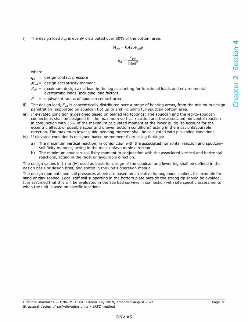
i) The design load Fvd is evenly distributed over 50% of the bottom area:
where:qd = design contact pressureMed= design eccentricity momentFvd = maximum design axial load in the leg accounting for functional loads and environmental
overturning loads, including load factorsR = equivalent radius of spudcan contact area
ii) The design load, Fvd is concentrically distributed over a range of bearing areas, from the minimum designpenetration (supported on spudcan tip) up to and including full spudcan bottom area.
iii) If elevated condition is designed based on pinned leg footings: The spudcan and the leg-to-spudcanconnections shall be designed for the maximum vertical reaction and the associated horizontal reactionin conjunction with 35% of the maximum calculated moment at the lower guide (to account for theeccentric effects of possible scour and uneven bottom conditions) acting in the most unfavourabledirection. The maximum lower guide bending moment shall be calculated with pin-ended conditions.
iv) If elevated condition is designed based on moment fixity at leg footings:
a) The maximum vertical reaction, in conjunction with the associated horizontal reaction and spudcan-soil fixity moment, acting in the most unfavourable direction.
b) The maximum spudcan-soil fixity moment in conjunction with the associated vertical and horizontalreactions, acting in the most unfavourable direction.
The design values in (i) to (iv) used as basis for design of the spudcan and lower leg shall be defined in thedesign basis or design brief, and stated in the unit's operation manual.The design moments and soil pressures above are based on a relative homogenous seabed, for example forsand or clay seabed. Local stiff soil supporting in the bottom plate outside the strong tip should be avoided.It is assumed that this will be evaluated in the sea bed surveys in connection with site specific assessmentswhen the unit is used on specific locations.
Chapter 2 Section 4
Offshore standards — DNV-OS-C104. Edition July 2019, amended August 2021 Page 36Structural design of self-elevating units - LRFD method
DNV AS

Guidance note:
Cases (i) and (ii) above are always to be checked together with one of the cases (iii) or (iv). Case (iii) or (iv) is checked based onthe leg footing assumption used in design.
For rectangular shaped spudcans of area (Ao), the design eccentricity moment may be taken as: Med = Fvd×Rn.Rn: Depending on weather direction, i.e. the radius (Rn) determined on basis of the centre of gravity of half of the spudcans totalfoot print area (Ao).
Corresponding design contact pressure: , where Ao = W1 x W2 see sketch below.
---e-n-d---o-f---g-u-i-d-a-n-c-e---n-o-t-e---
For other types of bottom support, e.g. mats special considerations should be made.
2.2.5 For internal compartments which are not freely vented to the sea when the mat or spudcan is restingon the seabed, the design loads shall include a head of water equal to the design water level as well as anyeffects of wave pressure.
2.3 Leg strength
2.3.1 The boundary conditions for the legs at the seabed shall be varied within realistic upper and lowerlimits when the scantlings of the legs are determined. The variation in boundary conditions shall take intoaccount uncertainties in the estimation of soil properties, non-linear soil-structure interaction, effects due torepeated loadings, possible scouring, etc.
2.3.2 When determining the forces and moments in the legs, different positions of the hull supports alongthe legs shall be considered.
2.3.3 Due attention shall be paid to the position and duration of load transfer between the leg and hull,including the shear force in the leg between supporting points in the hull structure.
2.3.4 Lattice-type legs shall be checked against overall buckling, buckling of single elements and punchingstrength of the nodes, see DNV-OS-C101 Ch.2 Sec.4.
2.3.5 Bottom impact forces occurring during installation and retrieval conditions shall be satisfactorilyaccounted in the design.
Chapter 2 Section 4
Offshore standards — DNV-OS-C104. Edition July 2019, amended August 2021 Page 37Structural design of self-elevating units - LRFD method
DNV AS
Guidance note:
A simplified analytical methodology relevant to installation and retrieval conditions is described in DNV-RP-C104.
---e-n-d---o-f---g-u-i-d-a-n-c-e---n-o-t-e---
2.4 Jackhouse support strengthSpecial attention shall be paid to the means for the leg support, the jackhouses, the support of the jackhouseto the main hull, and the main load transfer girders between the jackhouses.
2.5 Hull strengthScantlings of the hull shall be checked for the transit conditions with external hydrostatic pressure and inertiaforces on the legs as well as for the preloading and elevated conditions, see DNV-OS-C101 Ch.2 Sec.4.
2.6 Superstructures
2.6.1 The term 'superstructure' is used in this section to cover all decked structure on and above the upperdeck of hull, e.g. deckhouse, accommodation, ventilation duct housing, jacking houses and containers.
2.6.2 Superstructures shall as a minimum be designed for the design loads prescribed in Sec.3 [4.6].Scantlings shall meet the minimum thickness requirement of DNV-OS-C101 Ch.2 Sec.4 [6.2].
2.6.3 For self-propelled ship-shaped jack-ups, the design pressures shall be defined according to DNV rulesfor classification of ships, DNV-RU-SHIP Pt.3.
2.6.4 Flared sides of superstructure which is cantilevered over the side of the unit shall be designed forslamming loads during transit. The applicable pressure may be calculated based on DNV-RU-SHIP Pt.3 orDNV-RP-C205.
2.6.5 The combined global and local structural load effects on superstructures shall be considered in thedesign. Where accommodation form an integral part of the jacking houses the accommodation shall beincluded in global hull analyses.
2.6.6 Structure subject to immersion in damage stability conditions, where failure will lead to downfloodingbelow freeboard, shall be designed according DNV-OS-C101 Ch.2 Sec.6.
2.6.7 Containerized modules which may be manned during transit shall meet the same requirements as forstructure forming an integral part of the hull.
Guidance note:
The scantlings of unmanned containers on deck are not required the meet the requirements of this section, except the strength ofconnection to deck and supporting structure.
---e-n-d---o-f---g-u-i-d-a-n-c-e---n-o-t-e---
2.6.8 Variable functional loads on deck areas shall be based on DNV-OS-C101 Ch.2 Sec.2 [4.2] unlessspecified otherwise.
2.7 Support structure for lifting appliancesSupport structure for lifting appliances (including lifesaving launching equipment), shall comply with DNV-OS-C101 Ch.2 Sec.11 [1].
Chapter 2 Section 4
Offshore standards — DNV-OS-C104. Edition July 2019, amended August 2021 Page 38Structural design of self-elevating units - LRFD method
DNV AS
3 Scantlings and weld connectionsMinimum scantlings for plate, stiffeners and girders are given in DNV-OS-C101 Ch.2 Sec.4. The requirementsfor weld connections are given in DNV-OS-C101 Ch.2 Sec.8.
Chapter 2 Section 4
Offshore standards — DNV-OS-C104. Edition July 2019, amended August 2021 Page 39Structural design of self-elevating units - LRFD method
DNV AS

SECTION 5 FATIGUE LIMIT STATES
1 General
1.1 General
1.1.1 General requirements for the FLS are given in DNV-OS-C101 Ch.2 Sec.5. Guidance concerning designfatigue life calculation may be found in DNV-RP-C203 and DNV-RP-C104 Sec.7.
1.1.2 The design life of the unit shall be minimum 20 years.
1.1.3 This standard is based on the principle of regular surveys according to established inspection plans,and necessary repair are carried out. The survey regime shall be carried out within defined intervals. Unitsintended to stay on location for a prolonged survey period shall comply with the additional requirementsgiven in App.A.
1.1.4 Design fatigue factors (DFF) for self-elevating units shall be selected according consequence of afailure. Typical application of DFF values are described in Table 1 and Table 2 below depending of low andsubstantial consequence, respectively.
Guidance note:
The criterion of low consequence is in general met when the unit is proven redundant to resist single failure in combination withenvironmental loads according to the ALS criteria in DNV-OS-C101. Conventional and well proven lattice type legs are normallyconsidered to be redundant, i.e. the structure does not contain single members or member connections of which failures willhave substantial consequences. Conventional and well proven jacking structures in self-elevating units are normally robust forthe purpose of transferring loads in the leg to hull connection. In such cases a failure inside the jacking structure is normallyconsidered to have low consequences and DFF is depending on the access for inspection and repair according to Table 1. Noveldesign of leg bracing system or jacking structure requires redundancy considerations or other justification to demonstrate theconsequence of failure.
---e-n-d---o-f---g-u-i-d-a-n-c-e---n-o-t-e---
Table 1 Design fatigue factors in case of redundant structural elements/low consequence
Access for inspection and repair Typical jack-up structural element DFF
Access for inspection and repair in dry/clean conditions 1)
— hull and leg–to-hull interface— spudcan— leg structure— external mat structure.
1
Access for inspection and repair, butnot in dry/clean condition 1)
Submerged structure inspected in shelteredwater 2
No access for inspection or repair 31) Dry and clean condition include structure 1m above the lowest inspection level wheninspected afloat in sheltered water
Chapter 2 Section 5
Offshore standards — DNV-OS-C104. Edition July 2019, amended August 2021 Page 40Structural design of self-elevating units - LRFD method
DNV AS

Table 2 Design fatigue factors in case of not redundant structural elements/substantialconsequence
Access for inspection and repair Typical jack-up structural element DFF
Access for inspection and repair in dry/clean conditions 1)
— spudcan-to-leg connection— leg structure— leg-to-hull interface.
2
Access for inspection and repair, butnot in dry/clean condition 1)
Submerged structure inspected in shelteredwater 3
No access for inspection and repair 101) Dry and clean condition include structure 1m above the lowest inspection level wheninspected afloat in sheltered water
1.1.5 Local effects, e.g. due to:
— slamming— sloshing— vortex shedding— dynamic pressures.
shall be included in the fatigue damage assessment when relevant.
1.1.6 In the assessment of fatigue resistance, relevant consideration shall be given to the effects of stressconcentrations, including those occurring as a result of:
— fabrication tolerances, including due regard to tolerances in way of connections involved in fabricationsequences or section joints
— cut-outs— details at connections of structural sections (e.g. cut-outs to facilitate construction welding)— attachments.
1.1.7 Detailed analysis of critical connections (e.g. jacking support structure, leg and footing connection)shall be performed in order to evaluate the fatigue strength.
1.1.8 For proven details local finite mesh analysis may be omitted, provided relevant information of stressconcentration factors (SCFs) are available.
2 Fatigue analysis
2.1 GeneralThe required models and methods for fatigue analysis for self-elevating units or jack-ups are dependent ontype of operation, environment and design type of the unit. For units operating at deeper waters where thefirst natural periods are in a range with significant wave energy, e.g. for natural periods higher than 3 s, thedynamic structural response needs to be considered in the fatigue analysis.
2.2 Planned operationEnvironmental condition (scatter diagram) for the fatigue analysis shall be specified by the designer and shallconsider all intended future operations for the units design life.
Chapter 2 Section 5
Offshore standards — DNV-OS-C104. Edition July 2019, amended August 2021 Page 41Structural design of self-elevating units - LRFD method
DNV AS

2.3 Restricted operationThe analyses shall be performed utilising relevant site specific environmental data for the area(s) the unit willbe operated. The restrictions shall be described in the operation manual for the unit.
Guidance note:
Restricted operations may occur during in-service related to changes from planned operations.
---e-n-d---o-f---g-u-i-d-a-n-c-e---n-o-t-e---
2.4 Simplified fatigue analysis
2.4.1 Simplified fatigue analysis may be performed in order to establish the general acceptability of fatigueresistance, or as a screening process to identify the most critical details to be considered in a stochasticfatigue analysis, see [2.5].
2.4.2 Simplified fatigue analyses should be performed utilising appropriate conservative design parameters.Normally a two-parameter, Weibull distribution (see DNV-RP-C203 Sec.5) may be utilised to describe thelong-term stress range distribution, giving the following extreme stress range:
n0 = the total number of stress variations during the lifetime of the structure
=extreme stress range that is exceeded once out of n0 stress variations
The extreme stress amplitude, is thus given by
h = the shape parameter of the Weibull stress range distribution, see e.g. DNV-RP-C104[7.8]
a = the intercept of the design S-N curve with the log N axis, see DNV-RP-C203
Γ(1+m/h) = the complete gamma function, see DNV-RP-C203
m = the inverse slope of the S-N curve, see DNV-RP-C203
DFF = design fatigue factor
2.4.3 When the simplified fatigue evaluation involves utilisation of the dynamic stress responses resultingfrom the global analysis, e.g. 100 years, the response should be suitably scaled to the return period of thebasis, minimum design life of the unit. In such cases, scaling may be undertaken utilising the appropriatefactor found from the following:
ni = the number of stress variations in i years appropriate to the global analysis
= the extreme stress range that is exceeded once out of ni stress variations.
Chapter 2 Section 5
Offshore standards — DNV-OS-C104. Edition July 2019, amended August 2021 Page 42Structural design of self-elevating units - LRFD method
DNV AS

2.5 Stochastic fatigue analysis
2.5.1 Stochastic fatigue analyses shall be based upon recognised procedures and principles utilising relevantsite specific data or scatter diagram specified by the designer.
2.5.2 Simplified fatigue analyses should be used as a screening process to identify locations for which adetailed, stochastic fatigue analysis should be undertaken.
2.5.3 Fatigue analyses shall include consideration of the directional probability of the environmental data.Providing that it can be satisfactorily checked, scatter diagram data may be considered as being directionallyspecific. Scatter diagram for operations in specific nautic zones is given in DNV-RP-C205. Relevant wavespectra and energy spreading shall be utilised. Normally a Pierson-Moskowitch spectrum and a cos4
spreading function is utilised in the evaluation of self-elevating units. Further details are given in DNV-RP-C104.
2.5.4 Structural response shall be determined based upon analyses of an adequate number of wavedirections. Generally a maximum radial spacing of 15° should be considered. Transfer functions should beestablished based upon consideration of a sufficient number of periods, such that the number, and values ofthe periods analysed:
— adequately cover the wave data— satisfactorily describe transfer functions at, and around, the wave cancellation and amplifying periods(consideration should be given to take account that such cancellation and amplifying periods may bedifferent for different elements within the structure)
— satisfactorily describe transfer functions at, and around, the relevant excitation periods of the structure.
2.5.5 Stochastic fatigue analyses utilising simplified structural model representations of the unit (e.g. aspace frame model) may form basis for identifying locations for which a stochastic fatigue analysis, utilising adetailed model of the structure, should be performed (e.g. at critical intersections).
Chapter 2 Section 5
Offshore standards — DNV-OS-C104. Edition July 2019, amended August 2021 Page 43Structural design of self-elevating units - LRFD method
DNV AS

SECTION 6 ACCIDENTAL LIMIT STATES
1 Accidental events
1.1 GeneralThe general principles related to accidental events are given in DNV-OS-C101 Ch.2 Sec.6 [1.1].The following accidental scenarios shall be considered for jack-ups:
— collision— dropped objects— heat loads— explosion— unintended flooding.
1.2 Collision
1.2.1 Collision by a supply vessel against a leg of a self-elevating unit shall be considered for all elementsthat may be hit either by sideways, bow or stern collision. The vertical extent of the collision zone shall beestablished based on all possible combinations of vessel type and environmental conditions.
Guidance note:
Simplified procedures for calculation of vessel impact on self-elevating unit legs may be found in DNV-RP-C104 Sec.8.
---e-n-d---o-f---g-u-i-d-a-n-c-e---n-o-t-e---
1.2.2 A collision will normally only cause local damage of the leg. However, the global strength andoverturning stability of the unit shall also be checked. With lattice type legs the damaged chord or bracingand connections may be assumed to be non-effective with respect to residual strength of the unit aftercollision.
1.2.3 Dynamic effects and non-linear structural response (geometrical and material) should be considered aspart of the impact evaluation.
1.3 Dropped objects
1.3.1 Critical areas for dropped objects shall be determined on the basis of the actual movement of potentialdropped objects (e.g. crane or other lifting operation mass) relative to the structure of the unit itself. Wherea dropped object is a relevant accidental event, the impact energy shall be established and the structuralconsequences of the impact assessed.
1.3.2 Critical areas for dropped objects shall be determined on the basis of the actual movement of loadsassuming a minimum drop direction within an angle with the vertical direction:
— 5° in air— 15° in water.
Dropped objects shall be considered for vital structural elements of the unit within the areas given above.Guidance note:
A dropped object impact against a chord or bracing will normally cause complete failure of the element or its connections. Theseparts should be assumed to be non-effective for the check of the residual strength of the unit after the dropped object impact loadson the sea surface is only required for specific cases and where defined as an accidental event from a risk analysis.
---e-n-d---o-f---g-u-i-d-a-n-c-e---n-o-t-e---
Chapter 2 Section 6
Offshore standards — DNV-OS-C104. Edition July 2019, amended August 2021 Page 44Structural design of self-elevating units - LRFD method
DNV AS

1.4 Heat loadsHeat loads shall not lead to the following events before evacuation is completed:
— loss of global structural integrity— collapse of structure with successive damage to main bearing structure, accommodation, safety criticalequipment, and successive blockage of escape ways.Guidance note:
Heat loads on the sea surface is only required for specific cases and where defined as an accidental event from a risk analysis.
---e-n-d---o-f---g-u-i-d-a-n-c-e---n-o-t-e---
1.5 ExplosionsExplosions shall not lead to the following events:
— loss of global structural integrity— collapse of structure with successive damage to main bearing structure, accommodation, safety criticalequipment, and successive blockage of escape ways.Guidance note:
The following structures are relevant to be checked against explosions:
— blast walls
— process module
— flare tower
— internal turrets.
Information of relevant explosion pressure loads is given in DNV-OS-A101 Ch.2 Sec.1 [3.5].
---e-n-d---o-f---g-u-i-d-a-n-c-e---n-o-t-e---
1.6 Unintended flooding
1.6.1 Boundaries which shall remain watertight after unintended flooding shall be checked for the followingexternal water pressure.
— Static water pressure corresponding to the deepest equilibrium waterline in damaged condition obtainedfrom a damage stability calculation.
— Dynamic wave pressure from 1-year wave condition.
1.6.2 The resulting heel of the unit shall be combined with 1-year environmental conditions for local andglobal strength.
Guidance note:
The 1-year environmental loads may be disregarded if the material factor γM is set to 1.33.
---e-n-d---o-f---g-u-i-d-a-n-c-e---n-o-t-e---
1.6.3 Local exceeding of the structural resistance level may be acceptable provided redistribution of forcesdue to yielding, buckling and fracture is accounted for.
1.6.4 Wave pressure, slamming forces and green sea shall be accounted for in all relevant areas. Localdamage may be accepted provided progressive structural collapse and damage of vital equipment is avoided.
Chapter 2 Section 6
Offshore standards — DNV-OS-C104. Edition July 2019, amended August 2021 Page 45Structural design of self-elevating units - LRFD method
DNV AS
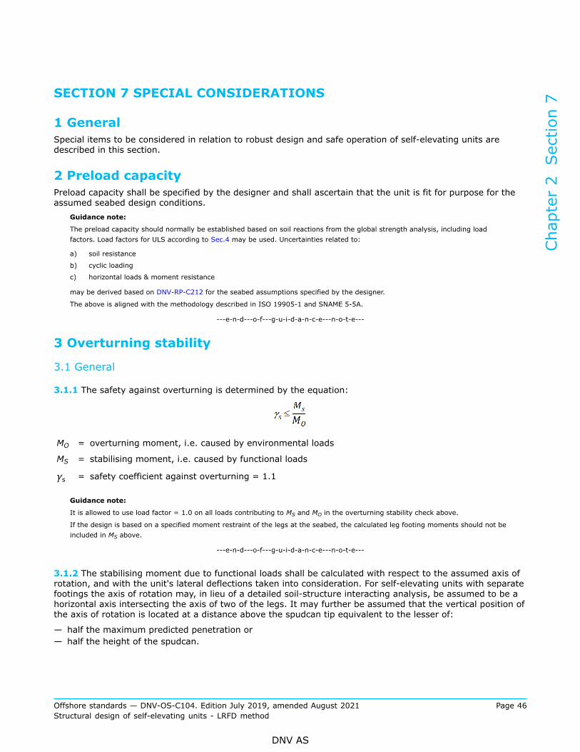
SECTION 7 SPECIAL CONSIDERATIONS
1 GeneralSpecial items to be considered in relation to robust design and safe operation of self-elevating units aredescribed in this section.
2 Preload capacityPreload capacity shall be specified by the designer and shall ascertain that the unit is fit for purpose for theassumed seabed design conditions.
Guidance note:
The preload capacity should normally be established based on soil reactions from the global strength analysis, including loadfactors. Load factors for ULS according to Sec.4 may be used. Uncertainties related to:
a) soil resistance
b) cyclic loading
c) horizontal loads & moment resistance
may be derived based on DNV-RP-C212 for the seabed assumptions specified by the designer.
The above is aligned with the methodology described in ISO 19905-1 and SNAME 5-5A.
---e-n-d---o-f---g-u-i-d-a-n-c-e---n-o-t-e---
3 Overturning stability
3.1 General
3.1.1 The safety against overturning is determined by the equation:
MO = overturning moment, i.e. caused by environmental loads
MS = stabilising moment, i.e. caused by functional loads
γs = safety coefficient against overturning = 1.1
Guidance note:
It is allowed to use load factor = 1.0 on all loads contributing to MS and MO in the overturning stability check above.
If the design is based on a specified moment restraint of the legs at the seabed, the calculated leg footing moments should not beincluded in MS above.
---e-n-d---o-f---g-u-i-d-a-n-c-e---n-o-t-e---
3.1.2 The stabilising moment due to functional loads shall be calculated with respect to the assumed axis ofrotation, and with the unit's lateral deflections taken into consideration. For self-elevating units with separatefootings the axis of rotation may, in lieu of a detailed soil-structure interacting analysis, be assumed to be ahorizontal axis intersecting the axis of two of the legs. It may further be assumed that the vertical position ofthe axis of rotation is located at a distance above the spudcan tip equivalent to the lesser of:
— half the maximum predicted penetration or— half the height of the spudcan.
Chapter 2 Section 7
Offshore standards — DNV-OS-C104. Edition July 2019, amended August 2021 Page 46Structural design of self-elevating units - LRFD method
DNV AS

For self-elevating units with mat support, the location of the axis of rotation may have to be speciallyconsidered.
3.1.3 The overturning moment due to wind, waves and current should be calculated with respect to the axisof rotation defined in [3.1.2]. The overturning stability shall be calculated for the most unfavourable directionand combination of environmental and functional loads according to the load plan for the unit. The dynamicamplification of the combined wave and current load effect shall be taken into account.
3.1.4 The lower ends of separate legs shall be prevented from sideway slipping by ensuring sufficienthorizontal leg and soil support.
4 Air gap
4.1 General
4.1.1 The air gap is defined as the distance between the underside of the hull and the LAT during operations
4.1.2 The unit shall be designed to enable the hull to be clear the wave crest including the combined effectsof astronomical tide and storm surge based on 100-year return period. The clearance is defined as thedistance between the underside of the hull (or any other vulnerable part attached to the hull, if lower) andthe wave crest elevation during the elevated operating and storm survival conditions.The clearance shall be the lower value of the followings:
— 1.2 m or— 10% of the combined astronomical tide, storm surge, and height of the wave crest based on water depthLAT.
Potential subsidence due to soil settlement shall be taken into account in air gap calculations.
4.1.3 Estimation of wave crest elevation is given in DNV-RP-C104.
4.1.4 A smaller distance may be accepted if wave impact forces on the deck structure are taken into accountin the strength and overturning analysis.
4.1.5 Clearance between the structure and wave shall be ensured in floating condition for appurtenancessuch as helicopter deck, etc.
4.1.6 Recommendations regarding the reserve leg length are given in DNV-RP-C104.
Chapter 2 Section 7
Offshore standards — DNV-OS-C104. Edition July 2019, amended August 2021 Page 47Structural design of self-elevating units - LRFD method
DNV AS

SECTION 8 ADDITIONAL REQUIREMENTS FOR WIND TURBINEINSTALLATION UNITS
1 General
1.1 IntroductionThe requirements of this section are supplementary technical requirements for self-elevating units utilised forinstallation and maintenance of offshore wind turbines. The requirements are intended to capture the uniqueoperational and design characteristics of wind turbine installation (WTI) units.
Guidance note:
Examples of typical design and operational considerations:
— high frequency of jacking and preloading operations
— large crane capacity
— main deck designed for frequent installation and demobilization of temporary equipment
— large open deck area
— use of crane with unit partly submerged or floating
— optimized design limitations with respect to the leg lowering condition
— weather restricted operations.
---e-n-d---o-f---g-u-i-d-a-n-c-e---n-o-t-e---
1.2 Environmental design criteriaThe environmental design criteria define the operability limits for the unit. In the event of weatherdeterioration during a weather restricted operation, the unit may either fully preload and elevate to survivalmode, or jack down and retreat to sheltered waters. For the latter option it is the responsibility of theoperator to ensure that the design limits for jacking down and transit are met.
Guidance note:
Guidance for weather restricted operations may be found in DNV-ST-N001 Sec.8 Offshore wind farm (OWF) installationoperations.
---e-n-d---o-f---g-u-i-d-a-n-c-e---n-o-t-e---
2 Structural categorisation, material and fabrication
2.1 General
2.1.1 Structural categorisation, material and fabrication shall follow the principles given in Sec.1.
2.1.2 The hull structure indicated with grey in Figure 1, may follow DNV rules for classification of shipsDNV-RU-SHIP Pt.3 Ch.3 Sec.1 and DNV-RU-SHIP Pt.2 for structural categorization, material selection andfabrication principles.
Chapter 2 Section 8
Offshore standards — DNV-OS-C104. Edition July 2019, amended August 2021 Page 48Structural design of self-elevating units - LRFD method
DNV AS

Figure 1 Structural categorization, material and fabrication
3 Design principles
3.1 GeneralGross scantlings may be used without any corrosion allowance provided a corrosion protection system inaccordance with DNV-OS-C101 Ch.2 Sec.10 is installed and maintained.
3.2 Transit condition
3.2.1 The hull girder longitudinal strength and local scantlings calculations may follow the requirementsgiven in DNV-OS-C102. For structure governed by the leg-to-hull interface loads the principles given in Sec.2shall be used.
Guidance note:
Units with large breadth over height ratio, excessive green sea and thruster ventilation may be limiting factors for transit.
During transport of wind turbine components the transit will normally be restricted by sea fastening capacity or the componentssusceptibility to excessive motions or accelerations.
---e-n-d---o-f---g-u-i-d-a-n-c-e---n-o-t-e---
3.2.2 If the unit is designed for unrestricted transit, the extreme values for motions and accelerations (i.e.probability level = 10-8), may be based on the DNV rules for ships DNV-RU-SHIP Pt.3 Ch.4 or a direct waveload analysis.
Guidance note:
For units with high metacentric height direct wave load analysis is recommended.
---e-n-d---o-f---g-u-i-d-a-n-c-e---n-o-t-e---
3.2.3 For hull strength calculations during crane operations in the floating condition, with the unit moored tothe quay, the global wave bending moment calculated from DNV ship rules may be reduced with 75%.
Chapter 2 Section 8
Offshore standards — DNV-OS-C104. Edition July 2019, amended August 2021 Page 49Structural design of self-elevating units - LRFD method
DNV AS

3.3 Elevated condition
3.3.1 The structural strength shall be documented for the maximum crane loading for all relevant cranepositions in combination with relevant environmental loads and functional loads.
3.3.2 For units where the crane foundation is built around one of the leg wells, special consideration shall begiven to the combined effects of leg and crane loading at the interfacing structure. Detailed local models arerequired to document sufficient structural strength.
3.3.3 It shall be ensured that the leg loads during the operational load case, combining crane andenvironmental loads, will not exceed the preload capacity.
Guidance note:
In operation it will be the responsibility of the operator to preload the unit to a magnitude which also covers the loads resultingfrom crane operation, as a site specific assessment normally only include the survival condition.
---e-n-d---o-f---g-u-i-d-a-n-c-e---n-o-t-e---
3.3.4 The stiffness of the hull shall be taken into account when assessing the vertical leg loads during craneoperation.
Guidance note:
It is not sufficient only to shift the center of gravity of the elevated weight in the global analysis as this may underestimate thevertical leg load in the leg located in the nearest vicinity of the main crane.
---e-n-d---o-f---g-u-i-d-a-n-c-e---n-o-t-e---
3.3.5 The global and local effect of loads due to installation equipment, e.g. piling templates and heavy ramequipment, shall be considered.
3.3.6 If the unit is intended to operate with the hull partly submerged, the structural strength andoverturning stability of the unit shall be proven for all relevant operational loads. Tide variations shall beincluded in the analysis.
3.4 Installation and retrieval
3.4.1 Partially submerged hull position which is reached during installation and retrieval may represent agoverning design condition for the legs. A design check shall be performed to assess the leg utilization duringthis condition. The results of the analysis (such as maximum leg bending moment and maximum verticalreactions) will define the directional limiting sea state for the installation and retrieval phase. The analysisneeds to take into account the dynamic effects, added mass and hydrodynamic forces on the hull and legs.
3.4.2 The unit shall be designed for the preload condition according to Sec.7.Guidance note:
As WTI units have a higher frequency of preloading/pre-driving operations than conventional jack ups, and are normally equippedwith large cranes which may be governing for leg design, leg equalization should be carefully monitored.
---e-n-d---o-f---g-u-i-d-a-n-c-e---n-o-t-e---
3.5 Deck cargo and heavy equipment
3.5.1 Loads caused by deck cargo and heavy equipment shall be accounted for in the design calculationsfor transit and operational phases. A range of deck load distributions shall be investigated and reflected
Chapter 2 Section 8
Offshore standards — DNV-OS-C104. Edition July 2019, amended August 2021 Page 50Structural design of self-elevating units - LRFD method
DNV AS

in the deck load plan. It is the responsibility of the operator to ensure that mission specific deck loads arecovered by the deck load plan. If the limitations of the deck load plan are exceeded in operation, it is theresponsibility of the operator to ensure that global strength of hull is still maintained.
Guidance note:
A range of loading scenarios should be included in the design basis of the unit to cover relevant deck loading scenarios inoperation. In order to improve flexibility of the cargo deck in operation the deck load plan for the unit should include distributedloads, point loads, line loads etc. Welds between deck plating and internal bulkheads/frames should be connected by fullpenetration in areas where high uplift loads are expected. For grillage welded temporarily on deck, extreme care should be takento ensure that deck plating is not deteriorated and welding defects are introduced in deck plating e.g. hydrogen induced cracking.Cargo handling vehicles should be specified in deck load plan.
---e-n-d---o-f---g-u-i-d-a-n-c-e---n-o-t-e---
3.5.2 The most severe accelerations at deck level during the bottom impact case shall be determined andincluded in the operation manual. These calculations will be used to design the sea fastening grillage installedon deck and to verify the existing hull supporting structure.
3.5.3 Strength calculations for equipment foundations shall include the effect of deck deflections in transitand preloading case.
Guidance note:
The requirement is relevant for equipment extending along the unit where forced deflections of the hull will cause loads in the seafastening grillage, e.g. sea fastening of transition pieces and mono piles. This may be solved with sliding support stools for the seafastening.
---e-n-d---o-f---g-u-i-d-a-n-c-e---n-o-t-e---
4 Fatigue limit states
4.1 Principles and methodology
4.1.1 The fatigue damage contributions from the operational phases shall be based on an assessment of theexpected area of operation, and the configuration of the operation with respect to the duration in the variousoperation phases (transit, jacking, preloading and elevated). The structure shall be designed for minimum 20years based on this assessment, see Sec.5 [1.1.2].
4.1.2 Due to the large number of repeated installation operations the units are expected to execute, thelegs, hull and jacking system should be designed sufficiently robust to sustain a large number of jackingoperations during the units design life. An appropriate assumption with regard to cargo weights should beconsidred for the fatigue calculations for the jacking system.
Guidance note:
Typically peak stresses in hull may be accepted for the ULS conditions on a case by case basis. Peak stresses occurring duringpreload should be documented with respect to fatigue as the peak stress will occur on a regular basis. Typical critical details arecut-out in bulkheads and decks in the near vicinity of the jacking houses.
---e-n-d---o-f---g-u-i-d-a-n-c-e---n-o-t-e---
4.1.3 Fatigue documentation for the legs should account for all the relevant operation conditions, e.g. transit,jacking and elevated. A sufficient number of load cycles for each condition should be considered based on theplanned operation of the unit. Special consideration shall be given to preload procedures used and how thisinfluence the number of load cycles in one pre-load operation.
Chapter 2 Section 8
Offshore standards — DNV-OS-C104. Edition July 2019, amended August 2021 Page 51Structural design of self-elevating units - LRFD method
DNV AS

Guidance note:
A logging procedure should be established to register number of performed jacking operations. This will enable the operator tomonitor the jacking history against design assumptions and provide input to the maintenance planning of the system.
---e-n-d---o-f---g-u-i-d-a-n-c-e---n-o-t-e---
Guidance note:
If not otherwise planned for it can be assumed that the unit will perform a total of 150 jacking operations per year during its lifetime.
---e-n-d---o-f---g-u-i-d-a-n-c-e---n-o-t-e---
4.1.4 All openings in main load bearing structure in jacking houses and hull structure indicated with greyshade in Figure 2 shall have a minimum corner radius of 0.15 times the breadth of the opening, minimum 25mm.
Figure 2 Areas applicable to specific corner radius requirement of openings
5 Accidental limit states
5.1 Leg stuckLimiting criteria shall be established for the stuck leg condition and the leg and hull shall be proven for theresulting loads.
Chapter 2 Section 8
Offshore standards — DNV-OS-C104. Edition July 2019, amended August 2021 Page 52Structural design of self-elevating units - LRFD method
DNV AS

Guidance note:
An accidental condition may occur for special soil conditions with soft clay, when retrieval of the leg may become impeded by theleg/spudcan being stuck in the sea bed. The retrieval of a stuck leg may cause overloading of leg, but also the jacking systemor hull beam may be critically loaded if the retrieval operation of the stuck leg is not carried out with caution. Allowable designparameters in a stuck leg condition may consist of heel/trim, draught, bottom fixity, leg pulling load etc. For the condition whena leg is stuck in the sea bottom, it may be required to partly submerge the hull in order to obtain sufficient lifting loads. This willlead to trim or heel of the unit, which may overload the legs, jacking system or supporting structure. During a leg stuck conditionat least two legs are needed to be in contact with the sea bottom to prevent any torsion loads on the stuck leg, unless the unit isdesigned to resist torsional loads to the leg due to environmental loads on the hull. The effect of rising tide should be included inthe operation procedure for a stuck leg. As for all self-elevating units the leg stuck scenario should be included in the operationalprocedures.
---e-n-d---o-f---g-u-i-d-a-n-c-e---n-o-t-e---
5.2 CollisionsFor units that operate without support from other units, the requirement given in Sec.6 may be waived. Thisshall be specified by the designer if relevant. If the operation is planned with support from other units, theconsequence of an impact should be considered both with regard to global and local integrity of the unit asgiven in Sec.6.
5.3 Scouring and additional settlementAdditional settlement of the legs in the sea bed, e.g. due to scouring, is not covered in this standard. Itis owner responsibility to carry out sufficient site specific assessment to minimize the risk of additionalsettlement and apply appropriate measures to detect settlement by RPD measurements, inclination and legload measurements.
Chapter 2 Section 8
Offshore standards — DNV-OS-C104. Edition July 2019, amended August 2021 Page 53Structural design of self-elevating units - LRFD method
DNV AS

CHAPTER 3 CLASSIFICATION AND CERTIFICATION
SECTION 1 CLASSIFICATION
1 General
1.1 Introduction
1.1.1 As well as representing DNV’s recommendations on safe engineering practice for general use by theoffshore industry, the offshore standards also provide the technical basis for DNV classification, certificationand verification services.
1.1.2 This chapter identifies the specific documentation, certification and surveying requirements to beapplied when using this standard for certification and classification purposes.
1.1.3 A complete description of principles, procedures, applicable class notations and technical basis foroffshore classification is given by the applicable DNV rules for classification of offshore units as listed in Table1.
Table 1 DNV rules for classification: Offshore units
Reference Title
DNV-RU-OU-0101 Offshore drilling and support units
DNV-RU-OU-0102 Floating production, storage and loading units
DNV-RU-OU-0103 Floating LNG/LPG production, storage and loading units
DNV-RU-OU-0104 Self-elevating units
1.2 Application
1.2.1 It is assumed that the units will comply with the requirement for retention of the class as defined inthe above listed service specifications.
1.2.2 Where codes and standards call for the extent of critical inspections and tests to be agreed betweencontractor or manufacturer and client, the resulting extent shall be agreed with DNV.
1.2.3 DNV may accept alternative solutions found to represent an overall safety level equivalent to thatstated in the requirements of this standard.
1.2.4 Any deviations, exceptions and modifications to the design codes and standards given as recognisedreference codes shall be approved by DNV.
1.2.5 Technical requirements given in DNV-OS-C101 Ch.2 Sec.7, related to serviceability limit states, are notmandatory as part of classification.
Chapter 3 Section 1
Offshore standards — DNV-OS-C104. Edition July 2019, amended August 2021 Page 54Structural design of self-elevating units - LRFD method
DNV AS

1.2.6 It is the operator’s responsibility to secure that loads/moments on the legs from gravity, wave andwind loads do not exceed (documented) design limitations as applied in line with Ch.2 Sec.2 (see also DNV-RU-OU-0101 Ch.1 Sec.5 [1]).
1.3 Basic hull classification scope
1.3.1 The basic classification requirements and scope for hull strength are given in Ch.2 of this standard andDNV-RU-OU-0104 Ch.3 Sec.1 [4].
Guidance note:
The following structures are not covered in scope unless specially agreed, or if additional class notations are requested.
— Topside modules, flare booms, derrick structure, offloading equipment, pipe rack structure, independent tanks, etc. Thesestructures are part of class scope when additional class notation is requested (e.g. PROD, DRILL), see DNV-RU-OU-0104.
— Deck grillage for transport of equipments.
— Access platforms, stairs and ladders.
— Lifting lugs.
---e-n-d---o-f---g-u-i-d-a-n-c-e---n-o-t-e---
1.4 Documentation
1.4.1 Documentation for classification shall be in accordance with the NPS DocReq (DNV Nauticus productionsystem for documentation requirements) and DNV-RU-SHIP Pt.1 Ch.3.
1.4.2 Limiting environment conditions and design capacities as used for basis of class approval, (see Ch.2Sec.2), shall be documented in the design brief.
Guidance note:
Statutory regulations may require these design limitations to be included in the operation manual, e.g. MODU code 14.1.2.8.
---e-n-d---o-f---g-u-i-d-a-n-c-e---n-o-t-e---
Chapter 3 Section 1
Offshore standards — DNV-OS-C104. Edition July 2019, amended August 2021 Page 55Structural design of self-elevating units - LRFD method
DNV AS
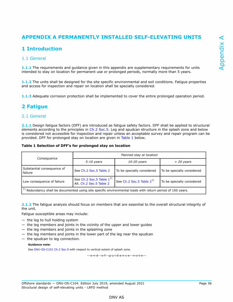
APPENDIX A PERMANENTLY INSTALLED SELF-ELEVATING UNITS
1 Introduction
1.1 General
1.1.1 The requirements and guidance given in this appendix are supplementary requirements for unitsintended to stay on location for permanent use or prolonged periods, normally more than 5 years.
1.1.2 The units shall be designed for the site specific environmental and soil conditions. Fatigue propertiesand access for inspection and repair on location shall be specially considered.
1.1.3 Adequate corrosion protection shall be implemented to cover the entire prolonged operation period.
2 Fatigue
2.1 General
2.1.1 Design fatigue factors (DFF) are introduced as fatigue safety factors. DFF shall be applied to structuralelements according to the principles in Ch.2 Sec.5. Leg and spudcan structure in the splash zone and belowis considered not accessible for inspection and repair unless an acceptable survey and repair program can beprovided. DFF for prolonged stay on location are given in Table 1 below.
Table 1 Selection of DFF’s for prolonged stay on location
Planned stay at locationConsequence
5-10 years 10-20 years > 20 years
Substantial consequence offailure See Ch.2 Sec.5 Table 2 To be specially considered To be specially considered
Low consequence of failure See Ch.2 Sec.5 Table 11)
Alt. Ch.2 Sec.5 Table 2 See Ch.2 Sec.5 Table 21) To be specially considered
1) Redundancy shall be documented using site specific environmental loads with return period of 100 years.
2.1.2 The fatigue analysis should focus on members that are essential to the overall structural integrity ofthe unit.Fatigue susceptible areas may include:
— the leg to hull holding system— the leg members and joints in the vicinity of the upper and lower guides— the leg members and joints in the splashing zone— the leg members and joints in the lower part of the leg near the spudcan— the spudcan to leg connection.
Guidance note:
See DNV-OS-C101 Ch.2 Sec.9 with respect to vertical extent of splash zone.
---e-n-d---o-f---g-u-i-d-a-n-c-e---n-o-t-e---
Appendix A
Offshore standards — DNV-OS-C104. Edition July 2019, amended August 2021 Page 56Structural design of self-elevating units - LRFD method
DNV AS

3 Inspection and maintenance
3.1 Facilities for survey
3.1.1 Surveys may be carried out on location based on agreed procedures outlined in a maintenance systemand survey arrangement, without interrupting the function of the unit. The following matters shall be takeninto consideration to be able to carry out surveys on location:
— arrangements and methods for survey of hull, legs and seabed foundation structure— corrosion protection of hull, legs and seabed foundation structure— underwater cleaning facilities.
3.1.2 The inspection plans should reflect possible stress concentrations in critical areas, fatigue criticality,and the previous operational and inspection histories.
3.1.3 For structure in and below the splash zone, designed with a DFF allowing for no inspection in operation,special considerations are required to monitor the condition of the leg and spudcan with respect to corrosionprotection, marine growth, scour and structural damages.
Appendix A
Offshore standards — DNV-OS-C104. Edition July 2019, amended August 2021 Page 57Structural design of self-elevating units - LRFD method
DNV AS

CHANGES – HISTORIC
July 2017 edition
Main changes July 2017
• Ch.2 Sec.1 Structural categorisation, material selection and inspection principles— Ch.2 Sec.1 [3.3.1] and Ch.2 Sec.1 [3.3.2]: Updated due to new material designations given in DNVGL-OS-B101.
January 2017 edition
Main changes January 2017
• Ch.2 Sec.8 Additional requirements for wind turbine installations units— Ch.2 Sec.8: New section addressing additional requirements for service notations, in particular windturbine installation units as based on content of former DNV-OS-J301.
April 2016 edition
Main changes April 2016
• General— References updated.— Clarification that worldwide service operation not is applicable for self-elevating units.
• Ch.1 Sec.1 Introduction— [1.3.5], [1.3.8] and [1.3.9]: New clauses added clarifying application of standard.
• Ch.2 Sec.1 Material selection— [3.3.2]: Clarification regarding use of VL E690 steel grade as alternative to VL F690 steel grade for racksand split tubes for thickness in the range of 80 mm to 250 mm.
• Ch.2 Sec.2 Design conditions— [2.3.2]: Updated clause taking out former explanatory text.— [2.3.5]: Requirement to torsional moment in tubular legs given.— [3.2.2]: Updated guidance note.
Changes – historic
Offshore standards — DNV-OS-C104. Edition July 2019, amended August 2021 Page 58Structural design of self-elevating units - LRFD method
DNV AS
July 2015 edition
Main changes July 2015
• GeneralThe revision of this document is part of the DNV GL merger, updating the previous DNV standard into a DNVGL format including updated nomenclature and document reference numbering, e.g.:
— Main class identification 1A1 becomes 1A.— DNV replaced by DNV GL.— DNV-RP-A201 to DNVGL-CG-0168. A complete listing with updated reference numbers can be found onDNV GL's homepage on internet.
To complete your understanding, observe that the entire DNV GL update process will be implementedsequentially. Hence, for some of the references, still the legacy DNV documents apply and are explicitlyindicated as such, e.g. Rules for Ships has become DNV Rules for Ships.
• Ch.2 Sec.2 Design principles— [2.2.6]: Reduced acceleration forces from 120% to 100% and guidance note updated.
Changes – historic
Offshore standards — DNV-OS-C104. Edition July 2019, amended August 2021 Page 59Structural design of self-elevating units - LRFD method
DNV AS

About DNVDNV is the independent expert in risk management and assurance, operating in more than 100countries. Through its broad experience and deep expertise DNV advances safety and sustainableperformance, sets industry benchmarks, and inspires and invents solutions.
Whether assessing a new ship design, optimizing the performance of a wind farm, analyzing sensordata from a gas pipeline or certifying a food company’s supply chain, DNV enables its customers andtheir stakeholders to make critical decisions with confidence.
Driven by its purpose, to safeguard life, property, and the environment, DNV helps tackle thechallenges and global transformations facing its customers and the world today and is a trustedvoice for many of the world’s most successful and forward-thinking companies.
WHEN TRUST MATTERS