domestic wastewater treatment mobilization … · engineer manual em 1110-3-172 may 1984...
TRANSCRIPT

ENGINEER MANUAL EM 1110-3-172 May 1984
ENGINEERING AND DESIGN
Domestic Wastewater Treatment
Mobilization Construction
DEPARTMENT OF THE ARMY CORPS OF ENGINEERS
OFFlCE OF THE CHIEF OF.ENGINEERS

DAEN-ECE-G
Engineer Manual No. 1110-3-172
DEPARTMENT OF THE ARMY u.s. Army Corps of Engineers
Washington, D.C. 20314
Engineering and Design DOMESTIC WASTEWATER TREATMENT
Mobilization Construction
EM 1110-3-172
11 May 1984
1. Purpose.· This manual provides guidance for the planning and design of domestic wastewater treatment plants at u.s. Army mobilization facilities.
2. Applicability. This manual is applicable to all field operating activities having mobilization construction responsibilities.
3. Discussion. Criteria and standards presented herein apply to construction considered crucial to a mobilization effort. These requirements may be altered when necessary to satisfy special conditions on the basis of good engineering practice consistent with the nature of the construction. Design and construction of mobilization facilities must be completed within 180 days from the date notice to proceed is given with the projected life expectancy of five years. Hence, rapid construction of a facility should be reflecteu in its design. Time-consuming methods and procedures, normally preferred over quicker methods for better quality, should be de-emphasized. Lesser grade materials should be substituted for higher grade materials when the lesser grade materials would provide satisfactory service and when use of higher grade materials· would extend construction time. Work items not immediately necessary for the adequate functioning of the facility should be def~rred until such time as they can be completed without delaying the mobilization effort.
FOR THE COMMANDER:
Colo Or ef
./ /
of Engineers

Engineer Manual No. 1110-3-172
DEPARTMENT OF THE ARMY US Army Corps of Engineers
Washington, D.C. 20314
Engineering and Design DOMESTIC WASTEWATER TREATMENT
Mobilization Construction
EM 1110-3-172
11 May 1984
Paragraph Page
CHAPTER 1.
CHAPTER 2.
CHAPTER 3.
CHAPTER 4.
CHAPTER 5.
GENERAL
Purpose and scope ••.••••••..•••• Overall design considerations .•• Definitions .................... .
CONSIDERATIONS FOR SITE SELECTION
Location ....................... . Space requirements •..•••••••..•. Access ••••••••••••••••••••••••.•
TREATMENT REQUIREMENTS
General considerations •••.•••.•. Evaluation of wastewater
treatment processes •.....••••••
BASIC DESIGN CONSIDERATIONS
General ........................ . Period of design .•••••••..•.••.. Estimating service demand ••••••• Volume of wastewater ••••••••..•• Wastewater characteristics •••••. Plant site preparation •••••••••. Plant layout •••••••••••••••.•••• Plant hydraulics •.•••.•••••••••• Plant auxiliary facilities •••••• Metering and instrumentation •••• Sampling . ...................... . Standard drawings •••••••••••••••
SELECTION OF TREATMENT PROCESSES
General ........................ . Recommended treatment scheme ••.. Alternative treatment designs ••• Regulatory requirements •••••...• Impact on receiving waters •••.••
1
1-1 1-2 1-3
2-1 2-2 2-3
3-1
3-2
4-1 4-2 4-3 4-4 4-5 4-6 4-7 4-8 4-9 4-10 4-11 4-12
5-1 5-2 5-3 5-4 5-5
1-1 1-1 1-1
2-1 2-1 2-1
3-1
3-1
4-1 4-1 4-1 4-2 4-3 4-4 4-4 4-5 4-5 4-6 4-6 4-6
5-1 5-1 5-4 5-4 5-4
EM 1110-3-172 11 May 84
CHAPTER 6.
CHAPTER 7.
CHAPTER 9.
CHAPTER lo;
FLOW-MEASURING DEVICES
General considerations ..•...•.•. Types of !low-measuring
Cf:eViC·eS •••• ~ ••••••••....••••.••
SCREENING
General. considerations •••...••.. Bclr screens .................... .
SEDIMENTATION
General considerations ..•.•••.•. Functions arid types of sedimentation units •...•••..•..
Design parameters •.........••..• Tank types and design ~eatur~s. ~ .................... .
Imhoff tanks .....•......••...... Sludge characteristics •.....•.••
WASTE STABILIZATION PONDS
Waste. stabilization pond classification: ..••.•...••..••.
Design par;aineters for waste .stcibilizal:ion ponds~.~ ..• ~ ...•.••
Pond facility requirements ..•••.
t~ICKLING F!LTER PLANTS
Gerierai corisiderations •• : •....•. pesi~ri bJ~is.~~~ criteria~······ N~~~lticitlori ln trlckilni : ~ ~ i ~~r$ ~. _, .• ... ; .. ~ ~·. ~ ~ ~ .. ~ ........ . ijy4hi~t ic coritp~nen ts .... ~ ...... . Other fiiter components ..•..• ~ .•
At±tvAfko stUridk ~tA~t~
n.. 11
Paragraph Page
6-1
6-2
7-1 7-2
8-1
8-2 8-3
8-4 8-5 8-6
9-1
9-2 9-3
10-1 10-2
ib-3 10-4 10-5
u..:1 il-2 ii-j ii-4 ii~s ii-6 ii-7
6-1
6-1
7-1 7-1
8-1
8-1 8-1
8-5 8-6 8-6
9-1
9-3 9-4
10-1 io-1
lQ-7 10-7 10-8
11-i il-l 11-s il-6, tt-to 11-H l1-'i2
CHAPTER 12.
CHAPTER 13.
CHAPTER 14.
CHAPTER 15.
APPENDIX A.
APPENDIX B.
APPENDIX C.
Figure 5-l.
5-2~
EM 1110-3-172 11 May 84
Paragraph Page
SLUDGE HANDLING, TREATMENT, AND DISPOSAL
General considerations ••.•••••.• Sludge pumping .. ............... . Sludge digestion •••••••.•.•••••• Sludge storage ••.•••..•••.••.••• Sludge drying . ................. . Sludge disposal •.•••••.••.•• ,, •.
DIS INFECTION
General considerations •••••••••. Types of chemical disinfectants. Design basis and criteria ••.•••. Chlorine feeding equipment •••••• Chlorine contact chambers ••••... Residual limitations ..••.•.•••••
SMALL SEWAGE TREATMENT FACILITIES
General considerations .••••••••. Septic tank design factors •••••• Subsurface irrigation design
factors ....................... . Package treatment plants .••••.••
SAFETY FEATURES
General considerations •••••.•••• Applicable standards •.• , •••••••• Safety features in plant design .. ...................... .
Safety equipment •••••••••••••••• Quick Shower ................... .
SAMPLE PROBLEMS
OXYGEN SOLUBILITY TABLE
REFERENCES
LIST OF FIGURES
12-1 12-2 12-3 12-4 12-5 12-6
13-1 13-2 13-3 13-4 13-5 13-6
14-1 14-2
14-3 14-4
15-1 15-2
15-3 15-4 15-5
12-1 12-1 12-1 12-6 12-7 12-7
13-1 13-1 13-1 13-2 13-5 13-5
14-1 14-1
14-1 14-2
15-1 15-1
15-1 15-2 15-3
A-1
B-1
C-1
Treatment scheme for flows less than or equal to 0.2 mgd. Treatment scheme for flows greater than 0.2 mgd.
iH
EM 1110-3-172 11 May 84
Figure 6-1. 7-1. 7-2. 8-1.
Table
8-2.
10-1.
10-2. 11-1.
3-1. 3-2.
3-3.
4-1. 4-2. 6-1.
6-2. 7-1. 8-1. 8-2. 8-3. 9-1.
9-2. 9-3.
10-1.
10-2. 10-3.
11-1. 11-2.
11-3. 12-1. 12-2.
12-3. 12-4. 13-1.
Parshall measuring flume. Schematic of heavy duty mechanically cleaned bar screen. Estimate of screenings collected on bar screens. Effective surface area adjustments for inlet-outlet losses in rectangular clarifiers, L:W=4
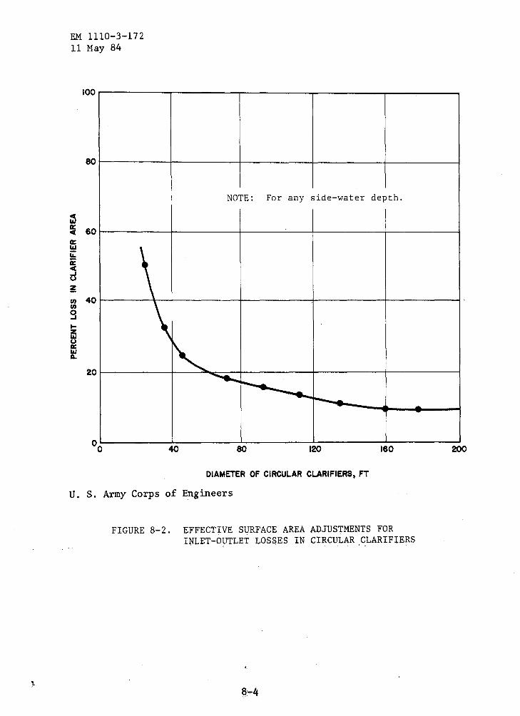
Effective surface area adjustments for inlet-outlet losses in circular clarifiers.
Common flow diagrams for single and two-stage high-rate trickling filters.
Trickling filter components. Activated sludge flow dia~rams.
LIST OF TABLES
Evaluation of wastewater treatment processes. Approximate performance data for various wastewater
processes. Operational characteristics of various treatment
processes. Sewage characteristics. Capacity factors. Types of measuring devices applicable to wastewater
treatment. Parshall flume flow values. Efficiencies of bar spacing. Surface loading rates for primary settling tanks. Surface loading rates for secondary sedimentation tanks. Typical characteristics of domestic sewage sludge. Classification and design parameters for wastewater treatment ponds.
Mechanical mixing energy required for oxygen dispersion. BOD removal efficiencies for aerated wastewater
treatment ponds. Design data and information for trickling filter processes.
Design recirculation rates for high-rate filters. Miscellaneous trickling filter component design criteria.
Design criteria for activated sludge modifications. Oxygen and air requirements for activated sludge modifications.
Power requirements for different types of aerators. Aerobic digestion design parameters. Standard-rate anaerobic digester capacity design criteria.
High-rate anaerobic digester capacity design criteria. Area required for sludge drying beds. Typical chlorine dosages required for sewage disinfection.
CHAPTER 1
GENERAL
EM 1110-3-172 11 May 84
1-1. -Purpose and scope. This manual prescribes general information and design criteria for guidance in th~ planning and design of domestic wastewater treatment plants at Army mobilization facilities.
1-2. Overall design considerations. Wastewater treatment plant design will be as simple as is commensurate with the required degree of treatment. Plants will be capable of treating normal laundry wastes together with sanitary wastewater. Some types of industrial waste may be admitted to wastewater treatment plants. These include cooling tower discharge, boiler blowdown, vehicle washrack wastewater, swimming pool filter discharges, and aircraft wash wast_es using biodegradable detergents. Pretreatment will be provided when conditions require it. In design for expansion of existing plants constituting new construction, criteria contained herein regarding flows and wastewater characteristics may be modified to conform to existing plant performance data if the plant has been in operation long enough to have established accurate data. Package treatment plants offer many advantages and will be considered for all feasible applications.
1-3. Definitions. The following definitions apply to this manual.
a. Auto-oxidation. Utilization of the endogenous phase of biological metabolism for the complete stabilization of organic wastes.
b. Biochemical oxygen demand (BOD). The quantity of oxygen used in the biochemical oxidation of organic matter in a specified time, at a specified temperature, and under specified conditions. It is not related to the oxygen requirements in chemical combustion, being determined entirely by the availability of the material as biological food and by the amount of oxygen utilized by the microorganisms during oxidation. Unless otherwise stated, BOD refers to the biochemical oxygen demand in 5 days at 20 degrees C.
c. Biological oxidation. The process whereby living organisms in the presence of oxygen convert the organic ma'tter contained in wastewater in to a more stable form-. - .
d. Biological treatment. Biological treatment systems are "living" systems which rely on mixed biological cultures to break down waste organics and remove organic matter from solution.
e. Chemical oxygen demand (COD). The oxygen equivalent of that portion oif o'rganic matter susceptible to oxidation by a strong chemical oxidan't.
1-1
EM 1110-3-172 11 May 84
f. Chlorine demand. The difference between the amount of chlorine added to the wastewater and the amount of residual chlorine remaining at the end of a specific contact time. The chlorine demand for given water varies with the amount of chlorine applied, time of contact, temperature, pH, and the nature and amount of impurities in the water.
g. Combined sewer system. A transport system which carries both sanitary wastewater and storm or surface water runoff.
h. Effluent. Any wastewater or liquid flow (raw, partially or completely treated) leaving a treatment process unit or operation.
1. Endogenous respiration. An auto-oxidation of cellular material, which takes place in the absence of assimilable organic material, to furnish energy required for the replacement of protoplasm.
j. Filterable solids. The quantity of material which passes through the filter paper when a quantity of water, sewage, or other liquid is filtered through an asbestos filter in a Gooch crucible.
k. Food to microorganism ratio. An aeration tank loading design parameter. Food may be expressed in pounds of suspended solids, COD, or BOD added per day to the aeration tank, and microorganisms may be expressed as mixed liquor suspended solids (MLSS) or mixed liquor volatile suspended solids (MLVSS) in the aeration tank.
1. Hydraulic surface loading. applied to a unit of surface area, filtration processes.
The flow (volume per unit time) applicable to trickling filter and
m. Influent. Wastewater or other liquid--raw or partially treated--flowing into a reservoir, basin, treatment process, or treatment plant.
n. Mixed liquor. A mixture of activated sludge and wastewater undergoing biological treatment 1n the aeration tank.
o. Mixed-liquor volatile suspended solids. volatile suspended solids in an aeration basin. to equal the biological solids concentration in
The concentration of It is commonly assumed
the basin.
p. Organic loading. Pounds of BOD applied per day to a biological reactor. Can also be related to reactor surface area or volume.
q. Oxygen uptake rate. The amount of oxygen being utilized by an activated sludge system during a specific time period.
1-2

EM 1110-3-172 11 May 84
r. Screening. A physical process preceding primary treatment. Its function is to protect subsequent treatment units and to minimize operational problems.
s. ~rimary treatment. Any physical or chemical treatment for the removal of settleable and floatable materials.
t. Raw sludge. Settled sludge directly tanks before decomposition has progressed. undigested sludge.
removed from sedimentation Frequently referred to as
u. Recirculation rate. The rate of return (given in percent) of part of the effluent from a treatment process to the head end of that process.
v. Secondary treatment. Any treatment process capable of producing an effluent containing a BOD and suspended solids (SS) concentration no greater than 30 mg/1 each.
w. Sanitary sewer. A sewer intended to carry domestic wastewater from homes, businesses, and industries.
x. Storm sewer. Storm water runoff collected and transported in a separate system of pipes.
y. Sludge age. In the activated sludge process, a measure of the length of time a particle of suspended solids has been undergoing aeration, expressed in days. It is usually computed by dividing the weight of the suspended solids in the aeration tank by the daily addition of new suspended solids having their origin in the raw waste.
z. Sludge density index. A term used in the expression of settling characteristics of activated sludge; 100/sludge volume index.
aa. Sludge volume index (SVI). A numerical expression of the settling characteristics of activated sludge. The ratio of the volume 1n milliliters of sludge settled from a 1,000-ml sample in 30 minutes to the concentration of mixed liquor in milligrams per liter multiplied by 1,000.
ab. Surface settling rate. One of the criteria for the design of settling tanks and gravity sludge thickeners, expressed in gallons per day per square feet of surface area in the tank.
ac. Suspended solids. Solids that either float on the surface of (or in suspension in) water, wastewater, or other liquids, and which are removable by laboratory filtering.
ad. Total oxygen demand (TOD). An instrumental method that is used to measure the organic content of water, wastewater, or other liquids.
1-3
EM 1110-3-172 11 May 84
In the test, organic substances and, to a minor extent, inorganic substances are converted to stable end products in a platinum-catalyzed combustion chamber.' The total oxygen demand is determined by monitoring the oxygen content present in the nitrogen carrier gas.
ae. Volatile solids. The amount of ~olid material present in the solid fraction of wastewater or sludge that is combustible at 550 degrees C,
af. Wasted sludge. The portion of settled solids from the final clarifier removed from the wastewater treatment processes to the solids handling facilities for ultimate disposal.

CHAPTER 2
CONSIDERATIONS FOR SITE SELECTION
EM 1110-3-172 11 May 84
2-1. Location. Major factors in site selection of treatment facilities are: topography; availability of a suitable discharge point; maintenance of reasonable distance from living quarters, working areas, and public use areas; and proposed facilities as reflected by the master plans. Plants, and wastewater treatment ponds reg~rdless of size, will not be less than one quarter mile from such facilities. The location of wastewater facilities must address the problems of unacceptable noise and odor levels. Wastewater treatment facilities should be located, to the extent possible, according to the following:
-Downwind of living quart~rs, working areas, and public use areas.
- Located in areas not subject to prolonged and/or frequent air stagnation, fog, or mist cover.
- Situated at a lower elevation than living quarters, working areas, and public use areas.
- Situated such that ground water at the wastewater facility flows away from occupied areas.
Exceptions to the one-quarter mile restriction can be made for cold climate module complexes where the treatment system is part of the module complex. Sewage treatment works will not be located within the same module as living quarters. Standard septic tank systems with sub-surface drain fields do not fall under the one-quarter mile restriction.
2-2. Space requirements. Sufficient. space must be allocated for suitable arrangement of all treatment units and associated plant piping.
2-3. Access. The site will be selected so that an all-weather road is available or can be provided for access to the plant.
2-1

CHAPTER 3
TREATMENT REQUIREMENTS
EM 1110-3-172 11 May 84
3-1 •• General considerations. Before treatment plant design is begun, treatment will be determined on the basis of meeting stream and effluent requirements set by the Federal and state governments.
a. Standards. The regulatory agencies will issue effluent standards covering the discharge of toxic pollutants. Strict limitations on discharges and, in some cases, complete prohibition may be imposed.
b. Pretreatment. Public Law 92-500, with subsequent amendments, requires pretreatment of pollutants which may interfere with operation of a sewage treatment plant or pass through such a plant untreated.
c. State regulations. The designer must review the applicable state guidelines before setting the treatment level or selecting the treatment processes.
d. Local regulations. In general, local governments do not specify requirements for wastewater treatment facilities per se. Construction of wastewater treatment facilities must conform to applicable zoning, Occupational Safety and Health Administration (OSHA) requirements, and to AR 200-1.
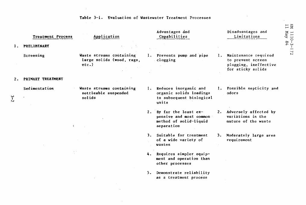
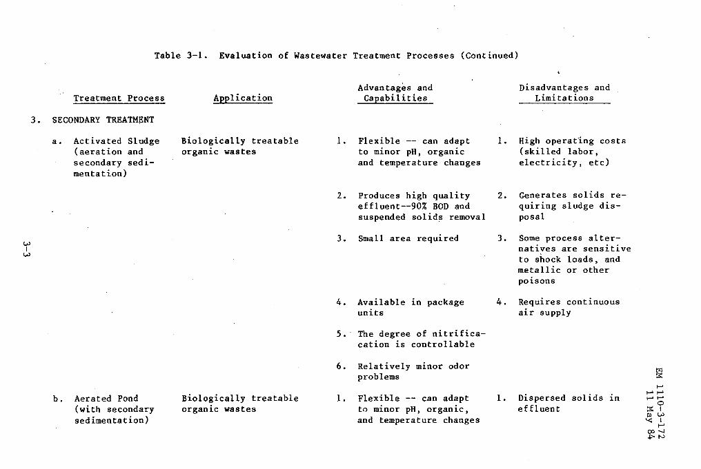
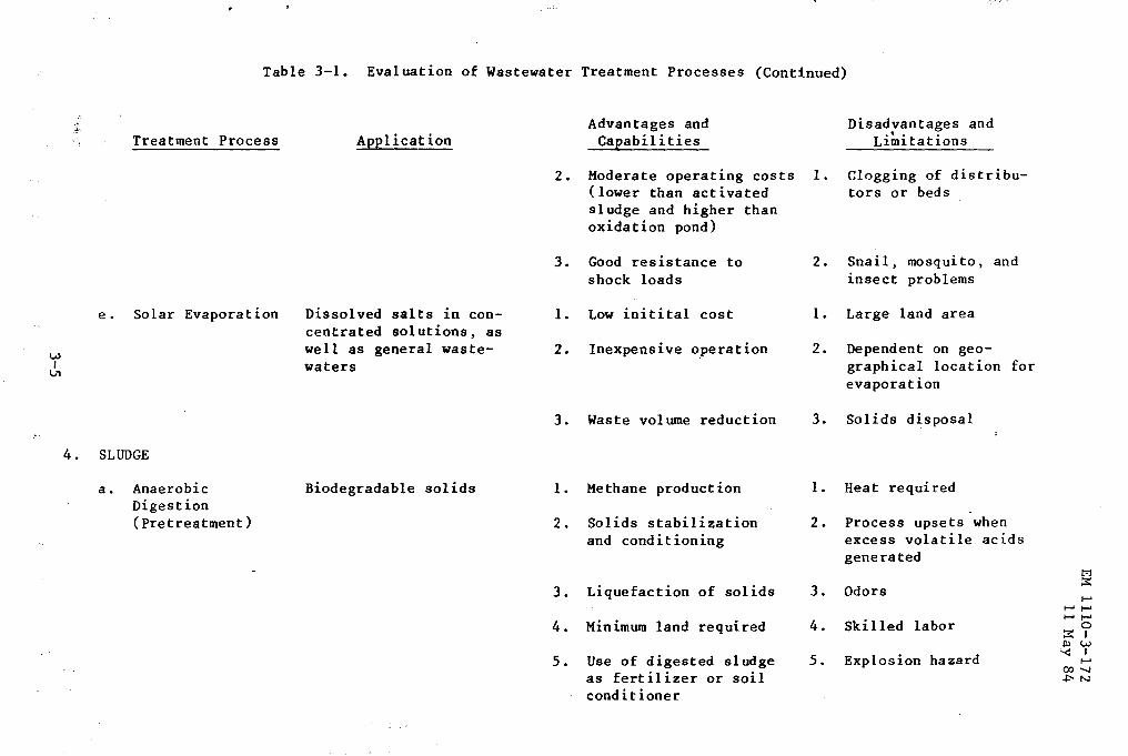
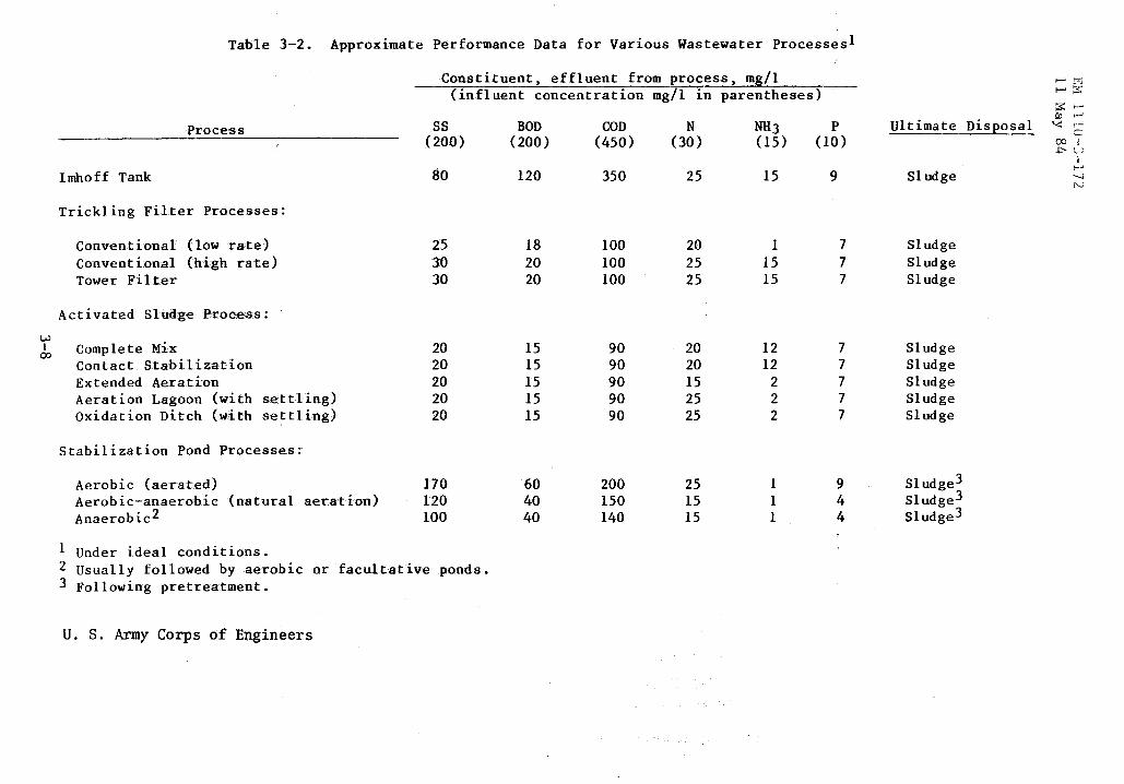
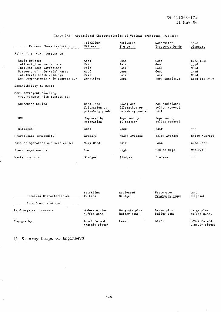
3-2. Evaluation of wastewater treatment processes. Table 3-1 provides a summary evaluation of wastewater treatment processes to be considered for mobilization construction. Tables 3-2 and 3-3 illustrate the applicable processes and their possible performance. All of the above will be used for guidance in selecting a process chain of treatment units.
3-1
w I
N
Treatment Process
1. PRELIMINARY
Screening
2. PRIMARY TREATMENT
Sedimentatioo
Table 3-1. Evaluation of Wastewater Treatment Processes
Application
Waste streams containing large solids (wood, rags, etc.)
Waste streams containing settleable suspended solids
Advantages and Capabilities
1. Prevents pump and p1pe clogging
Disadvantages and Limitations
1. Maintenance required to prevent screen plugging, ineffective for sticky solids
1. Reduces inorganic and 1. Possible septicity and organic solids loadings odors to subsequent biological units
2. By far the least expensive and most common method of solid-liquid separation
3. Suitable for treatment of a wide variety of wastes
4. Requires simpler equipment and operation than other processes
5. Demonstrate reliability as a treatment process
2. Adversely affected by variations in the nature of the waste
3. Moderately large area requirement
1-'trl 1-':S::
:S::t-' !lJ 1-'
'<: 1-' 0
001 ~w
I 1-' '--! N
w I
w
Table 3-1. Evaluation of Wastewater Treatment Processes (Continued)
Treatment Process
3. SECONDARY TREATMENT
a. Activated Sludge (aeration and secondary sedimentation)
b. Aerated Pond (with secondary sedimentation)
Application
Biologically treatable organic wastes
Biologically treatable organic wastes
Advantages and Capabilities
1. Flexible -- can adapt to minor pH, organic and temperature changes
2. Produces high quality effluent--90% BOD and suspended solids removal
3. Small area required
4. Available in package units
5. · The degree of nitrificacation is controllable
6. Relatively minor odor problems
1. Flexible-- can adapt to minor pH, organLc, and temperature changes
Disadvantages and Limitations
1. High operating costs (skilled labor, electricity, etc)
2. Generates solids requiring sludge disposal
3. Some process alternatives are sensitive to shock loads, and metallic or other poisons
4. Requires continuous air supply
1. Dispersed solids Ln effluent

Tal:>le 3-1. Evaluation of Wastewater Treatment Processes (Continued)
.Treatillent Pr<Q:Gess
c. .":Aer:obic...;..,.Anaerobic ·"Pondsl
.d. .Triekling Silter
••. ~pplication
Biolqgioally •. treatable or:ganic .. wastes
Biologically treatable or.ganic wastes
Advantages and Capabilities
Disadvantages and Limitations
2. Inexpensive construction 2. Affected by seasonal temperature variations
3. Minimum attention
4. Moderate effluent {80-95% BOD Removal)
1. Low Construction costs
2. Non-skilled operation
3. Moderate quality effluent {80-95% .BOD Removal)
4. Removes some nutrients from wastewaters
1. Moderate quality effluent {80-90% BOD Removal)
3. Operating problems (ice, solids settlement, etc)
4. Moderate power costs
5. Large area required
6. No color reduction
1. Large land area required
2. Algae in effluent
3. Possible septicity and odors
4. Potential weed growth, mosquito, and insect problems
1-'tr:i ....... ::;;::
::;;:: ....... Ill 1-' "< 1-'
0 <X> I .j::'-W
I 1-' -....! N
w I
VI
Table 3-1. Evaluation of Wastewater Treatment Processes (Continued)
Treatment Process
e. Solar Evaporation
4. SLUDGE
a. Anaerobic Digestion (Pretreatment)
Application
Dissolved salts in con-centrated solutions, as well as general waste-waters
Biodegradable solids
Advantages and Capabilities
2. Moderate operating costs I. (lower than activated
3.
I.
2.
3.
1.
2.
3.
4.
5.
sludge and higher than oxidation pond)
Good resistance to shock loads
Low initital cost
Inexpensive operation
Waste volume reduction
Methane production
Solids stabilization and conditioning
Liquefaction of solids
Minimum land required
Use of digested sludge as fert i1 izer or soil conditioner
2.
1.
2.
3.
1.
2.
3.
4.
5.
Disadvantages and • t • •
L1m1tat1ons
Clogging of distributors or beds
Snail, mosquito, and insect problems
Large land area
Dependent on geo-graphical location for evaporation
Solids disposal
Heat required
Process upsets when excess volatile acids generated
Odors
Skilled labor
Explosion hazard
1:':1 ::;:: ,.....
,..... ,..... ,..... ,.....
0 ::;:: I Ill w '< I ,..... 00......, +:-N
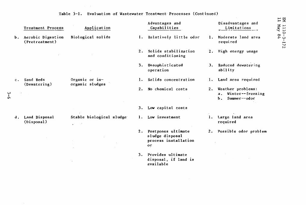
Table 3-1. Evaluation of Wastewater Treatment Processes (Continued)
Treatment Process
b. Aerobic Digestion (Pretreatment)
c. Sand Beds (Dewatering)
d. Land Disposal (Disposal)
Application
Biological solids
Organic or inorganic sludges
Stable biological sludge
Advantages and Capabilities
1. Relatively little odor
2. Solids stabilization and conditioning
3. Unsophisticated operation
1. Solids concentration
2. No chemical costs
3. Low capital costs
1. Low investment
2. Postpones ultimate sludge disposal process installation or
3. Provides ultimate disposal, if land 1S
available
Disadvantages and Limitations
1. Moderate land area required
2. High energy usage
3. Reduced dewatering ability
1. Land area required
2. Weather problems: a. Winter--freezing b. Summer--odor
1. Large land area required
2. Posiible odor problem
1-'·t'=:l 1-':::S:
:::;::: ...... Ill ...... '< ......
0 001 +=-w
I ...... --.J N

w I ......
Table 3-1. Evaluation of Wastewater Treatment Processes (Continued)
Treatment Process
e. Sanitary Landfill (Disposal)
Application Advantages and
Capabilities
Dewatered biological sludges 1. Low investment (30-35% solids)
2. Suitable for undigested sludges, odorous or toxic materials
3. Land reclamation
U. S. Army Corps of Engineers
Disadvantages and Limitations
1. Ground-water contamination
2. Requires ·cover material and compaction
3. Hauling costs
1-' 1-' 1-' 1-' 1-'
0 ::S:I Ill w '< I
1-' oo ...... .J:'-N
w
Table 3-2. Approximate Performance Data for Various Wastewater Processes!
Process
Imhoff Tank
Trick! ing Filter Processes:
Conventional (low rate) Conventional (high rat.e) Tower Filter
Activated Sludge Proc:ess:
Constituent, effluent from process, mg/1 (influent concentration mg/1 in parentheses)
ss (200)
ao
25 30 30
BOD (200)
120
18 20 20
COD (450)
350
100 100 100
N (30)
25
20 25 25
NH3 (15)
15
1 15 15
p (10)
9
7 7 7
~ Complete Mix 20 20 20 20 20
15 15 15 15 15
90 90 90 90 90
20 20 15 25 25
12 12
2 2 2
7 7 7 7 7
Contact Stabilization Extended Aeration Aeration Lagoon (with settling) Oxidation Ditch (with settling)
Stabilization Pond Processes:
Aerobic (aerated) Aerobic-anaerobic (natural aeration) Anaerobic2
1 Under ideal conditions.
170 120 100
2 Usually followed by aerobic or facultative ponds. 3 Following pretreatment.
U. S. Army Corps of Engineers
60 40 40
200 150 140
25 15 15
1 1 1
9 4 4
Ultimate Disposal
Sludge
Sludge Sludge Sludge
Sludge Sludge Sludge Sludge Sludge
Sludge3 Sludge3 Sludge3
1-'l:::c 1-'::S:
~FIll 1-'
'<: r-' G
00 i ~~-;
I 1-' ---.1 N
EM 1110-3-172 11 May 84
Table 3-3. Operational Characteristics of Various Treatment Processes
Process Characteristics
Reliability with respect to:
Basic process I nfl uen t .flow variations Influent load variations Presence of industrial waste Industrial shock loadings Low temperatures ( 20 degrees
Expandibility to meet:
More stringent discharge requirements with respect to:
Suspended Solids
BOD
Nitrogen
Operational complexity
C.)
Ease of operation and maintenance
Power requirements
Waste products
Process Characteristics
Site Considerations
Land area requirements
Topography
Trick! ing Filters ----
Good Fair Fair Good Fair Sensitive
Good; add filtration or polishing ponds
Improved by filtration
Good
Average
Very Good
Low
Sludges
Trick! ing Filters
Moderate plus buffer zone
Level to moderately sloped
U. S. Army Corps of Engineers
3-9
Activated Sludge __
Good Fair Fair Good Fair Good
Good; add filtration or polishing ponds
Improved by filtration
Good
Above Average
Fair
High
Sludges
Activated Sludge
Moderate plus buffer zone
Level
Wastewater Treatment Ponds
Good Good Good Good Fair Very Sensitive
Add additional solids removal unit
Improved by solids removal
•Fair
Below Average
Good
Low to High
Sludges
Wastewater Treatment Ponds
Large plus buffer zone
Level
Land Disposal
Excellent Good Good Good Good Good (to 0°C)
Below Average
Excellent
Moderate
Land Disposal
Large plus buffer zone.
Level to moderately sloped

CHAPTER 4
BASIC DESIGN CONSIDERATIONS
EM 1110-3-172 11 May 84
4-1. General. The required treatment is determined by the influent characteristics, the effluent requirements, and the treatment processes that produce an acceptable effluent. Influent characteristics are determined by laboratory testing of samples from the waste stream or from a similar waste stream, or are predicted on the basis of standard waste streams. Effluent quality requirements are set by Federal, interstate, state, and local regulatory ~gencies.
4-2. Period of design. The service life for wastewater treatment works at mobilization facilities will be 5 years. Design of wastewater treatment facilities must account .for all current flows as well as anticipated flows occurring during this service period.
4-3. Estimating service demand.
a. Population data. Army installation populations are controlled according to work assignment; therefore, this information can be obtained directly from personnel records and requirement projections.
b. Hydraulic loadings. The hydraulic waste loads to be used for resident personnel is 100 gpcd. The hydraulic waste load to be used for nonresident personnel is 30 gpcd.
c. Organic loadings. The organic waste loads to be used for resident personnel are given in table 4-1. The values shown in table 4-1 for that portion of the contributing population served by garbage grinders will be increased by 65 percent for BOD values and 100 percent for suspended solids. Contributing compatible industrial or commercial flow must be evaluated for waste loading on a case-by-case basis.
Table 4-1. Sewage Characteristics
Item Resident Personnel pounds/capita for 24 hours
Suspended Solids Biochemical Oxygen Demand
0.20 0.20
Nonresident Personnel pounds/capita
for 8-hour shift
0.10 0.10
d. Population equivalents. Suspended solids and organic loading can be interpreted as population equivalents when population data constitute the main basis of design. Typical population equivalents applicable to Army facilities were given in table 4-1. These equivalent values can also be used to convert nondomestic waste loads into population design values.
4-1
EM 1110-3-172 11 May 84
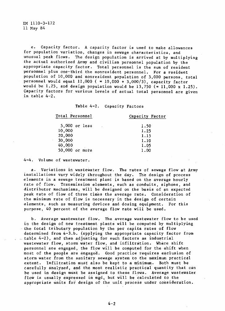
e. Capacity factor. A capacity factor is used to make allowances for population variation, changes in sewage characteristics, and unusual peak flows. The design population is arrived at by multiplying the actual authorized Army and civilian personnel population by the appropriate capacity factor. Total personnel is the sum of resident personnel plus one-third the nonresident personnel. For a resident population of 10,000 and nonresident population of 3,000 persons, total personnel would equal 11,000 ( = 10,000 + 3,000/3), capacity factor would be 1.25, and design population would be 13,750 (= 11,000 x 1.25). Capacity factors for various levels of actual total personnel are given in table 4-2.
Table 4-2. Capacity Factors
Total Personnel Capacity Factor
5,000 or less 1.50 10,000 1.25 20,000 1.15 30,000 1.10 40, OQO 1.05 50,000 or more 1.00
4-4. Volume of wastewater.
a. Variations in wastewater flow. The rates of sewage flow at Army installations vary widely throughout the day. The design of process elements in a sewage treatment plant is based on the average hourly rate of flow. Transmission elements, such as conduits, siphons, and distributor mechanisms, will be designed on the basis of an expected peak rate of flow of three times the average rate. Consideration of the minimum rate of flow is necessary in the design of certain elements, such as measuring devices and dosing equipment. For this purpose, 40 percent of the average flow rate will be used.
b. Average wastewater flow. The average wastewater flow to be used in the design of new treatment plants will be computed by multiplying the total tributary population by the per capita rates of flow determined from 4-3.b. (applying the appropriate capacity factor from table 4-2), and then adjusting for such factors as industrial wastewater flow, storm water flow, and infiltration. Where shift personnel are engaged, the flow will be computed for the shift when most of the people are engaged. Good practice requires exclusion of storm water from the sanitary sewage system to the maximum practical extent. Infiltration must also be kept to a minimum. Both must be carefully analyzed, and the most realistic practical quantity that can be used in design must be assigned to these flows. Average wastewater flow is usually expressed in mgd, but will be calculated to the appropriate unfts for desigh of the unit proce~s under consideration.
4-2
EM 1110-3-172 11 May 84
c. Industrial flow. most Army installations. survey measurement is the occurrence (continuous or also be known.
Industrial wastewater flows will be minimal at When industrial flows are present, however, best way to ascertain flow rates. Modes of intermittent) and period of discharge must
d. Storm water flow. Storm water flows are significant in treatment plant design only when combined sewer systems are served. Combined sewer systems will not be permitted in new Army installations. Separate sewers are required, and only sanitary flows are to be routed through treatment plants.
e. Ground water infiltration. In calculating wastewater volumes for new facilities, allowance must be made for infiltration as given in EM 1110-3-174.
4-5. Wastewater characteristics.
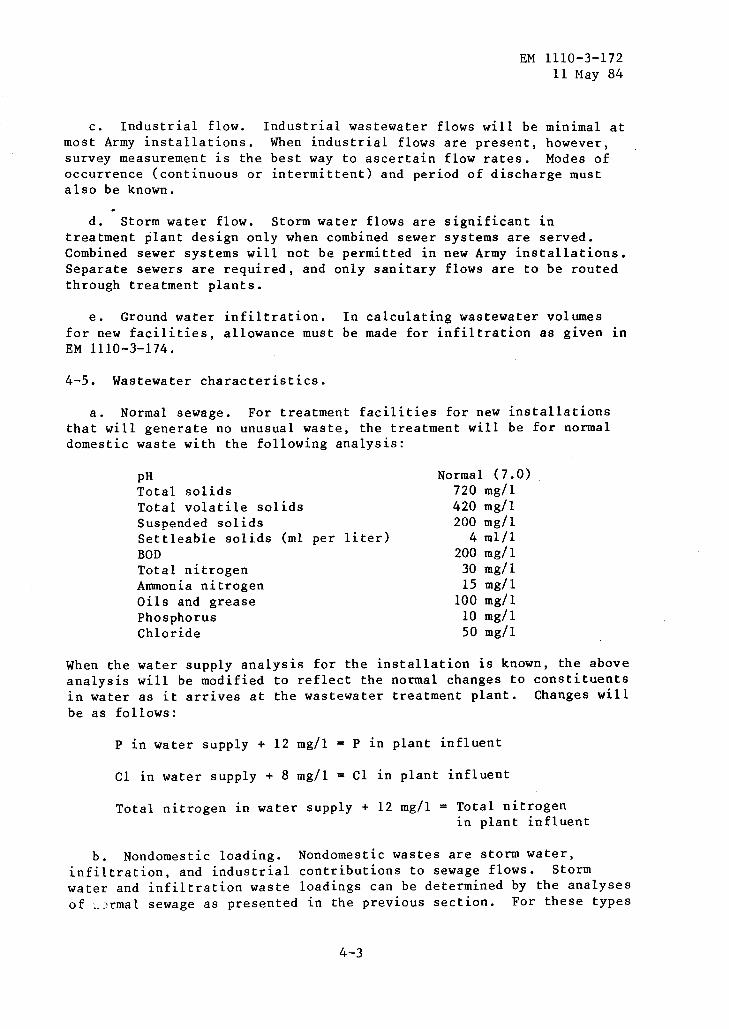
a. Normal sewage. For treatment facilities for new installations that will generate no unusual waste, the treatment will be for normal domestic waste with the following analysis:
pH Total solids Total volatile solids Suspended solids Settleable solids (ml per liter) BOD Total nitrogen Ammonia nitrogen Oils and grease Phosphorus Chloride
Normal (7.0) 720 mg/1 420 mg/1 200 mg/1
4 ml/1 200 mg/1
30 mg/1 15 mg/1
100 mg/1 10 mg/1 50 mg/1
When the water supply analysis for the installation is known, the above analysis will be modified to reflect the normal changes to constituents in water as it arrives at the wastewater treatment plant. Changes will be as follows:
P in water supply + 12 mg/1 = P in plant influent
C1 in water supply + 8 mg/1 = C1 in plant influent
Total nitrogen 1n water supply + 12 mg/1 = Total nitrogen 1n plant influent
b. Nondomestic loading. Nondomestic wastes are storm water, infiltration, and industrial contributions to sewage flows. Storm water and infiltration waste loadings can be determined by the analyses of ,.•rmal sewage as presented in the previous section. For these types
4-3

EM 1110-3-172 11 May 84
of flows, the major loading factors are suspended solids, BOD, and coliform bacteria. Industrial waste loadings can also be characterized to a large extent by normal sewage analyses. However, industrial waste contains contaminants not generally found in domestic sewage and is much more variable than domestic sewage. This is evident in terms of pH, BOD, COD, grease and oils, and suspended solids; other analyses (e.g., heavy metals, thermal loading, and dissolved chemicals) may also be necessary to characterize an industrial waste fully. Each industrial wastewater must be characterized individually to determine any and all effects on treatment processes.
4-6. Plant site preparation. Site drainage is an important factor in design of wastewater treatment facilities. Capacities of drainage structures will be designed in accordance with requirements of EM 1110-3-136. All treatment units must be protected from surface wash by proper shielding and drainage.
4-7. Plant layout.
a. Arrangement of treatment units. The first step in determining the best arrangement of units is to arrange all units sequentially according to the flow of wastewater through the system. The resulting hydraulic profile for wastewater flow will determine the relative vertical alinement of each of the plant's units. Final arrangement of the units then results from adaptation of site features to the treatment plant's functional and hydraulic requirements. Allowance must also be made for the area of operation and maintenance of the treatment units. If sufficient head is available for gravity flow, the hydraulic requirements will control the plant layout. Greater flexibility in arranging the treatment plant units is achieved with intermediate pumping of wastewater, although pumping should be eliminated wherever possible. The treatment plant must operate during emergency conditions such as power failures, and also during periods of maintenance work on treatment units. Dual units should be provided in all feasible cases to provide operational reliability and flexibility.
b. Conduits and pipelines. Conduits and pipes will be arranged in such a manner as to reduce space and cost requirements. They will be designed to handle the expected maximum flows through the treatment plant.
c. Bypasses and overflows. Provisions for bypassing individual treatment units will be made so that each unit can be taken out of service without interrupting the plant operation. Bypasses will not be provided for screens, chlorination units, nor other unit processes where duplicate units are available. Overflows will be used to prevent hydraulic overloading of treatment units, especially biological treatment units. Return of flows not treated or alternate treatment ~u~t be provi~ed.
4-4

EM 1110-3-172 11 May 84
d. Treatment plant discharge. Outfall sewers will be extended to the low-water level of the receiving body of water or to submergence required by regulatory authority to insure satisfactory dispersion of the plant effluent. Provisions for effluent sampling and monitoring are required. The design will assure the structural integrity of the outfall, prevent failure due to erosion, and prevent backflow during flooding.
4-8. Plant hydraulics.
a. Hydraulic loadings. The overall head allowances required for various types of wastewater treatment plants are as follows:
Type of Plant
Primary treatment Activated sludge Trickling filters
Low-rate High-rate, single-stage
Head Reguired feet
3 to 6 3 to 6
18 to 24 10 to 15
b. Limiting velocities. A minimum velocity of 2.0 fps at design average flow is required for channel flow. At minimum flows, a minimum velocity of 1.5 fps is required to prevent suspended solids from settling in flow channels.
c. Head loss. The total head loss through a treatment plant is the sum of head losses in the conveyance of wastewater between elements of the treatment process and the losses of head through treatment units. Head losses from wastewater conveyance are due to frictional losses in conduits, bends, and fittings, and allowances for free-fall surface and for future expansions. EM 1110-3-174 gives detailed guidance and charts for computing head losses in pipes and conduits. Head losses through process equipment are dependent on the specific units and are specified by their manufacturers or by the design engineer.
4-9. Plant auxiliary facilities.
a. General. A potable water supply will be provided. Sanitary facilities, toilet, shower, and lavatory with hot and cold water supply will be provided, except for installations with less than 0.1 mgd capacity. The potable water line will incorporate a backflow prevention device to prevent the contamination of the water supply. Emergency power for essential equipment will be provided. Adequate working and storage space is required for all plants. The general plant layout will facilitate operation and maintenance of the treatment units and their appurtenances.
4-5
EM 1110-3-172 11 May 84
b. Controls and monitoring. The plant arrangement will take into consideration the related control and monitoring requirements. Laboratory facilities will be provided either on or off site for conducting the necessary analytical testing for the purpose of process control and compliance with regulatory requirements.
4-10. Metering and instrumentation.
a. Continuous recording of flow. Wastewater flow rates will be monitored and recorded for purposes of evaluating treatment plant performance and will also be used when treatment charges are involved. Continuous flow measurement is necessary in order to monitor diurnal variations in flow which may affect treatment plant efficiency. Flow rates must also be taken into account when sampling wastewater quality.
b. Monitoring equipment for process control. Monitoring equipment will be used to indicate and/or record flow quantities and, if justified, pressure, temperature, liquid levels, velocities, and various quality parameters.
(1) Monitoring at pumping stations. In sewage pumping stations, flow measurement is necessary to control periodic pump operation. Watt-hour meters and pump time meters will be used to insure balanced pump usage among all units in multiple-pump installations.
(2) Monitoring of biological treatment. Trickling filter monitoring will include flow measurement of influent, effluent, and recirculation lines, and also volume of sludge pumped to or from the digesters. These parameters are used in determining and controlling hydraulic and organic loading as well as in controlling settling tank efficiencies. Activated sludge treatment will require the same monitoring with the addition of MLVSS and air-supply monitoring.
4-11. Sampling. Wastewater sampling at various points in the sewage treatment process is useful in evaluating operation efficiency. This can be used internally in order to optimize the process and is also used by regulatory agencies to judge whether treatment plant regulations are satisfied. Sampling is also used to establish changes when treating industrial wastes. Provisions for sampling sites must be made in .. the plant design. The type of sampling provisions, composite or grab sample collection, will be dictated by the type of sampling required in the National Polltitant Discharge Elimination System (NPDES) discharge permit. Forward flow, recycled flow, sludge flow, chlorine residual, pH, and dissolved oxygen are some of the process control parameters that can be monitored on a continuous basis.
4-12. Standard drawings. Standard drawings have been prepared fqr the reconnnended treatment schemes outlined in chapter 5. These drawings may be altere~ depending on local conditions and criteria.
4-6
CHAPTER 5
SELECTION OF TREATMENT PROCESSES
EM 1110-3-172 11 May 84
5-1 .• General. The method for treating domestic wastewater flows at mobilization facilities will be dictated by existing physical, economic, and environmental conditions at the site. Such conditions include the availability of land, fuel, building materials, construction and process equipment, skilled construction and operations forces, and transportation facilities. Designs requiring low energy consumption, unskilled labor, and relative ease of operation should be stressed. ·
5-2. Recommended treatment scheme. A wastewater treatment scheme has been presented within the mobilization scenario. This scheme will be given first consideration with regard to the restrictions and requirements outlined above. The treatment units and processes specified in this scheme will be in accordance with the guidelines and criteria presented in their respective chapters of this manual. The recommended treatment scheme presents two methods of operation and the decision on which method to use dependent on flow quantity.
a. For flows less than or equal to 0.2 mgd. Imhoff tanks followed by waste stabilization ponds will be used. Figure 5-1 presents a schematic diagram for this treatment operation. Standard drawings and specifications identified by Mobilization Drawing Code M 830-00-A have been prepared to assist the designer of this treatment method.
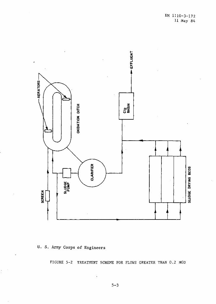
b. For flows greater than 0.2 mgd but less than or equal to l mgd. Oxidation ditches followed by secondary clarification will be used. Figure 5-2 presents a schematic diagram for this treatment operation. Standard drawings and specifications identified by Mobilization Drawing Code M830-00-B have been prepared to assist the designer of this treatment method.
c. For flows greater than 1.0 mgd. Treatment of flows greater than 1.0 mgd will entail the duplication of the major units employed in the oxidation ditch scheme. For example, a 1.5 mgd plant will require use of two oxidation ditches and two clarifiers. Duplication of auxiliary units such as screens, sludge beds, and chlorine basins would be determined on a case-by-case basis.
d. For all flows. For all methods, disinfection by chlorination is optional depending on need to disinfect which is dependent on water use downstream of the discharge point. Sludges generated from each process will be dewatered by the use of sand-drying beds and be disposed of at
5-l

EM 1110-3-172 11 May 84
tz
3 .... .... 11.1
r-1 I I L ...J
I I U. S. Army Corps of Enginee~s
FtOURE 5-1 tREATMENt SCH~ME·Fok FLOWS LESS THAN OR EQUAL TO 0.2 MGD
5.-2
"'a. (!)~ Q:::)
z 3a. 1&.1 en 1&.1 a: &l
U. S. Army Corps of Engineers
..... z 1&.1 :::) ..J LL. LL. 1&.1
EM 1110-3-172 11 May 84
en Q 1&.1 ID
(!) z ):: a: Q
~ Q
3 en
FIGURE 5-2 TREATMENT SCHEME FOR FLOWS GREATER THAN 0.2 MGD
5-3
EM 1110-3-172 11 May 84
a sanitary landfill or by land application. As a minimum, manually-cleaned screens should be provided at the head of the plant to. remove heavy debris which may hinder the treatment processes.
5-3. Alternative treatment designs. Although the treatment methods presented above are the ones to be considered first for mobilization work, situations may arise which make their use unfeasible. One example would be the scarcity of land for'ponds and oxidation ditches. In this case, a treatment method requiring less land area would be mandated. Such a design could include the more compact activated sludge systems. Another example would be the immediate availability of trickling filter equipment making this system more desirable. All legitimate alternatives to the recommended treatment scheme should be identified and investigated by the evaluation of restricting parameters and governing conditions.
5-4. Regulatory requirements. The NPDES Permit obtained from the local Federal regulatory agency office by the installation to which the permit is issued will generally determine the treatment requirements. Effluent requirements for new Federal facilities that establish maximum pollution discharge limitations will be provided by coordination of the Corps of Engineers Design Office with the regulatory agency.
5-5. Impact on receiving waters. The toxicity, coliform count, BOD, COD, settleable solids, and nutrient load of the waste stream must be considered in determining its impact on the receiving waters. The impact is dependent on the ability of the water body to assimilate the waste stream. Dissolved oxygen (DO) levels provide one of the means to interpret the impact. Increased waste loads cause increased mic~obial activity, exerting a high oxygen demand and a lowering of the DO level of the receiving water. The DO level affects the viability of most aquatic life and is used in setting stream standards. Seasonal variations must be considered.

CHAPTER 6
FLOW-MEASURING DEVICES
EM 1110-3-172 11 May 84
6-1. General considerations. Flow-measuring devices are required for all wa~tewater treatment plants of the types to measure various influent, effluent, and in-process wastewater flows. Equipment for indicating, totalizing, and recording the effluent wastewater flow will be provided for all secondary-treatment plants with flows greater than 0.10 mgd and smaller plants in special cases. For plants less than 0.10 mgd, recording and totalizing equipment will be provided as required to assure effluent limitation within regulations imposed by the regulating authority. In plants requiring recirculation of wastewater, meters with means for indicating the rates of recirculation are required. Weirs, Parshall flumes, and magnetic flow meters are satisfactory for measuring wastewater flow, Parshall flumes being generally preferable for Army projects when measuring influent or effluent. Measuring devices will be designed, or specified, with a view toward obtaining the accuracy of measurement throughout the expected range of flow. Principles of design of such devices are covered in standard handbooks.
6-2. Types of flow-measuring devices. The following paragraphs describe the types that are suitable for use in wastewater treatment plants. For additional comments refer to table 6-1.
a. Weirs. Weirs shall be located in a channel so that the flow will not be disturbed by turbulence and in such a manner that the depth of flow over the weir can be observed and recorded. When continuo~s recording is required, the float will be installed in a chamber separated from the main channel of flow, but connected thereto by piping.
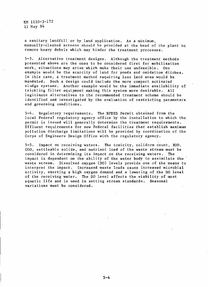
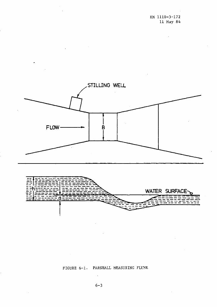
b. Parshall flumes. A typical Parshall flume is shown in figure 6-1. This device has many advantages: the loss of head is minimal; it is self-cleaning; flow measurement can be made in open-channel flow; and it has no moving parts to malfunction. The downstream water-surface elevation above the flume approach floor, a, must not exceed 65 percent of water elevation, b, upstream of the flume. The flume will be designed with the narrowest throat practicable for the conditions under consideration. The stilling well shown in figure 6-1 provides a quiescent zone in which to measure the height, h. Flow through a Parshall flume, with a throat width of at least 1 foot but less than 8 feet under free flow conditions, may be estimated by the following formula:
0.026 Q 4Bhl.S22B
6-1

0\ I
N
Table 6-1. Types of Measuring Devices Applicable to Wastewater Treatment
Primary Measurement and Type of Device
Flow
Open channels:
Head area meters -
Flume!
Velocity meters -
Propeller
Pressure pipelines:
Differential producers
Level
Staff gage
Floa.t
Probes
Use Waste Disposal
Plant influent, bypass lines
Primary effluent, plant effluent
Clean liquids up to 2 percent solids
Wet wells, floating cover digester
Wet wells
Wet wells
lsuspended matter does not hinder operation.
2Notmally requires free fall for discharge.
U. S. Army Corps of Engineers
Limitations General
More costly than weir
Produces greater head loss than flume
Requires fixed cross-sectional area. Low head loss
Fluid must be under positive head at all times
Use for indication only. Location must be visible
Indication near tank
Do not use for indication. Fluid must be electrolyte
Capacity
13 gpm to 3,000 mgd
Virtually unlimited
30 gpm to virtually unlimited, 0.9 to 20 fps
Unlimited
Unlimited
Unlimited
....... t:t:l
....... ;:s:: ;:s:: ....... Ill ....... '< .......
0 00 I +:-- w
I ....... -....! N
10 to l
100 to l
100 to l
100 to I
FLOW---..
------------------------------------------------__ h _______ _ -- ---------- --------------------
STILUNG WELL
B
EM 1110-3-172 11 May 84
---- -~~~'!!"!!~~~~~~~~-------~---:0::-:0:-=-:-=-=-~~~-=-
FIGURE 6-1. PARSHALL MEASURING FLUME
6-3
EM 1110-3-172 11 May 84
where:
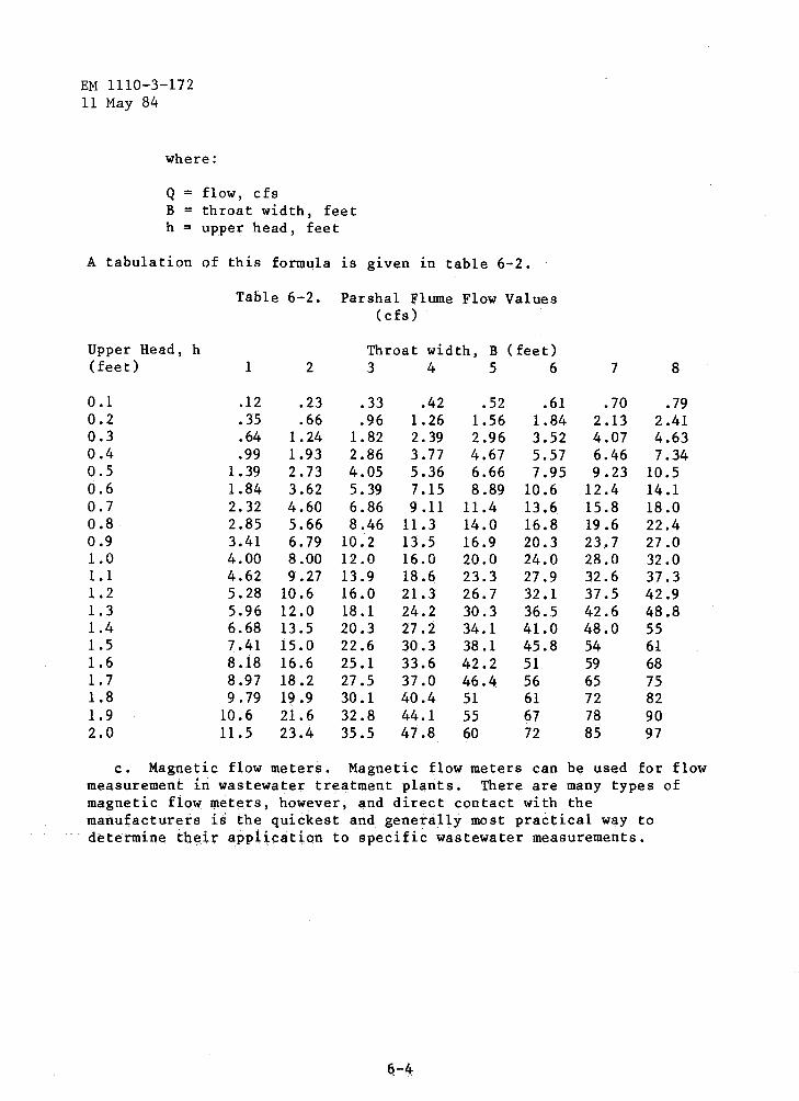
Q = flow, cfs B = throat width, feet h = upper head, feet
A tabulation of this formula is given in table 6-2.
Upper Head, h (feet)
0.1 0.2 0.3 0.4 0.5 0.6 0.7 0.8 0.9 1.0 1.1 1.2 1.3 1.4 1.5 1.6 1.7 1.8 1.9 2.0
Table 6-2. Parshal Flume Flow Values ( cfs)
1
.12
.35
.64
.99 1.39 1.84 2.32 2.85 3.41 4.00 4.62 5.28 5.96 6.68 7.41 8.18 8.97 9.79
10.6 11.5
2
.23
.66 1.24 1.93 2.73 3.62 4.60 5.66 6.79 8.00 9.27
10.6 12.0 13.5 15.0 16.6 18.2 19 .9 21.6 23.4
Throat width, B (feet) 3 4 5 6
.33
.96 1.82 2.86 4.05 5. 39 6.86 8.46
10.2 12.0 13.9 16.0 18.1 20.3 22.6 25.1 27.5 30.1 32.8 35.5
.42 1.26 2.39 3. 77 5.36 7.15 9.11
11.3 13.5 16.0 18.6 21.3 24.2 27.2 30.3 33.6 37.0 40.4 44.1 47.8
.52 1.56 2.96 4.67 6.66 8.89
11.4 14.0 16.9 20.0 23.3 26.7 30.3 34.1 38.1 42.2 46.4 51 55 60
.61 1.84 3.52 5.57 7.95
10.6 13.6 16.8 20.3 24.0 27.9 32.1 36.5 41.0 45.8 51 56 61 67 72
7
.70 2.13 4.07 6.46 9.23
12.4 15.8 19 .6 23,. 7 28.0 32.6 37.5 42.6 48.0 54 59 65 72 78 85
8
.79 2.41 4.63 7.34
10.5 14.1 18.0 22.4 27.0 32.0 37.3 42.9 48.8 55 61 68 75 82 90 97
c. Magnetic flow meters. Magnetic flow meters can be used for flow measurement in wastewater treatment plants. There are many types of magnetic flow meters, however, and direct contact with the manufacturers is the quickest and generally most practical way to determine th~ir application to specific wastewater measurements.

CHAPTER 7
SCREENING
EM 1110-3-172 11 May 84
7-1. General considerations. Screening is a process necessary to protec~ pumps and subsequent treatment units of a wastewater treatment plant. Its main function is to remove sticks, stones, rags, trash, and other debris.
7-2. Bar screens.
a. Description and function. The pr~mary function of coarse screening is protection of downstream facilities rather than effective removal of solids from the plant influent. All screens used in sewage treatment plants or in pumping stations may be divided into the following classifications:
(1) Trash racks, which have a clear opening between bars of 1-1/2 to 4 inches and are usually cleaned by hand, by means of a hoist, or possibly by a power-operated rake.
(2) Standard mechanically cleaned bar screen, with clear openings from 1/2 to 1-1/2 inches (figure 7-1).
(3) Fine screen, with openings 1/4 inch wide or smaller.
b. Design basis. Screens will be located where they are readily accessible. An approach velocity of 2 fps, based on average flow of wastewater through the open area, is required for manually cleaned. bar screens. For mechanically cleaned screens, the approach velocity will not exceed 3.0 fps at maximum flows.
(1) Bar spacing. Clear openings of 1 inch are usually satisfactory for bar spacing, but 1/2 to 1-1/2 inch openings may be used. The standard practice will be to use 5/16-inch by 2-inch bars up to 6 feet in length and 3/8-inch by 2-inch or 3/8-inch by 2-1/2-inch bars up to 12 feet in length. The bar will be long enough to extend above the maximum sewage level by at least 9 inches.
( 2) Size of screen channel. The maximum velocity through the screen bars, based on maximum normal daily flow, will be 2.0 fps. For wet weather flows or periods of emergency flow, a maximum velocity of 3.0 fps will be allowed. This velocity will be calculated on the basis of the screen being entirely free from debris. To select the proper channel size, knowing the maximum storm flow and the maximum daily normal flow, the procedure is as follows: the sewage flow (mgd) multiplied by the factor 1.547 will give the sewage flow (cfs). This flow in cfs divided by the efficiency factor obtained from table 7-1 will give the wet area required for the screen channel. The minimum width of the channel should be 2 feet, and the maximum width of the
7-1

EM lll0-3-172 11 May 84
.. '
~: . ... ' .. ~: ,... " . , ..
4
"' . -
FLOW--
FtGIJitE 7-L sci\EMAt1C OF Jlf}.VY DUTY MECRA~tcf.LLY CLEANED BAR SCREE~
7-2
EM 1110-3-172 11 May 84
channel should be 4 feet. As a rule it is desirable to keep the sewage in the screen channel as shallow as possible in order to keep down the head loss through 'the plant; therefore, the allowable depth in the channel may be a factor in determining the size of the screen. In any event, from the cross-sectional area in the channel, the width and depth of the channel can be readily obtained by dividing the wet area by the depth or width, whichever is the known quantity.
Table 7-1. Efficiencies of Bar Spacing
Bar Size Openings Efficiency inches inches
1/4 1 0.800 5/16 1 0.768 3/8 1 o. 728 7/16 1 0.696 1/2 1 0.667
(3) Velocity check. Although screen channels are usually designed on the basis of maximum normal flow or maximum storm flow, it is important to check the velocities which would be obtained through the screen from minimum or intermediate flows. The screen will be designed so that at any period of flow the velocities through the screen do not exceed 3 fps under any flow condition.
(4) Channel configuration. Considerable attention should be given to the design of the screen channel to make certain that conditions are as favorable as possible for efficient operation of the bar screen. The channel in front of the screen must be straight for 25 feet. Mechanical screens with bars inclined at an angle of 15 degrees from the vertical will be installed.
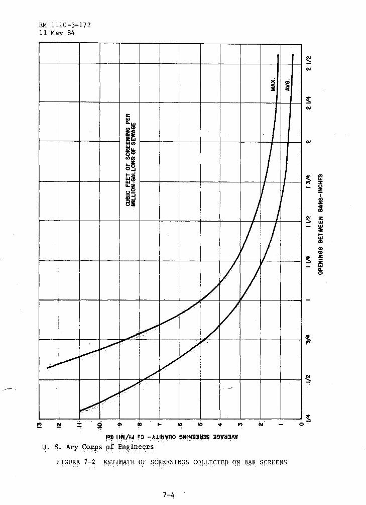
(5) Screenings. The graph shown in figure 7-2 will be used to predict the average amount of screenings that will be collected on the bar screen. The information required to make this estimate is flow and bar spacing. Grinding of the screenings (and returning them to the wastewater flow), incineration, and landfilling operations are satisfactory methods for disposal of the screenings.
(6) Design procedure. Select bar size and spacing and determine efficiency factor. Determine number of units desired. Divide total maximum daily flow or total maximum storm flow by the number of screens desired to obtain maximum flow per screen. The procedure is then as follows:
Maximum daily flow 1n mgd x 1.547 = maX1mum daily flow in cfs.
Maximum storm flow 1n mgd x 1.547 = max1mum storm flow in cfs.
7-3
EM 1110-3-172 11 May 84
~ ~ ,..
~ '
--
a: llJ
:~ !I Zl&.l ~it.~ en
5~ 00 ..... fj o_,
tu! ~~ ~::;
~~
/ v
v v
I
/ I
v v v v / v v /
' ,.,.~
'D~ 1. IY4/f~ ~:> - ~.L~~~nO ~NINiiij:>S i9YYiJ\Y
u. s. Ary ~qrps pf Engineers ' '•' ' ' ' . . . •' ' . . ~
7-4
x ~ C( :& C(
"
I v I
I 1
v v
~ 0-

cfs = net area through bars for max1mum daily flow. 2
cfs = net area through bars for maximum storm flow. 3
EM 1110-3-172 11 May 84
Which~ver of the above gives the larger value should be used for design.
Net area in square feet = gross area or channel cross-Efficiency coefficient for bars section wet area.
Minimum width of bar rack = 2 feet; Maximum width = 4 feet
Channel cross-section wet area = Corresponding depth or width Maximum desired width or depth
These figures are based on recessing channel walls 6 inches each side for chain tracks and screen frame. The overall width of screen frame is 12 inches greater than width of bar rack. If not possible to recess walls, the channel should be made 1 foot wider than figured above.
(7) Sample calculation. Assume:
Maximum daily flow = 4 mgd Maximum storm flow = 7 mgd Maximum allowable velocity through bar rack for maximum daily flow = 2 fps.
Then, using the design procedure in the preceding paragraph:
Maximum daily flow= 4 x 1.547 = 6.188 cfs. Maximum storm flow= 7 x 1.547 = 10.829 cfs.
Since Q = Av, 6.188 = Ax 2, and the net area A through the bars is 3.094 square feet. For a maximum allowable velocity through the bar rack of 3 fps during maximum storm flow, the net area through the bars must be 10.829/3 = 3.61 square feet. The gross area will be based on the larger of the two net areas, in this case 3.61 square feet. A rack consisting of 2-inch by 5/16-inch bar~ spaced to provide clear openings of 1 inch has an efficiency of 0.768 (table 7-1), yeilding:
Gross Area= 3.61 = 4.70 square feet 0.768
The channel width in this case might be established at 3 feet, in which case the water depth would be 4.70/3.0 = 1.57 feet. This is a theoretical water depth which may be affected by subsequent plant
7-5
EM 1110-3-172 11 May 84
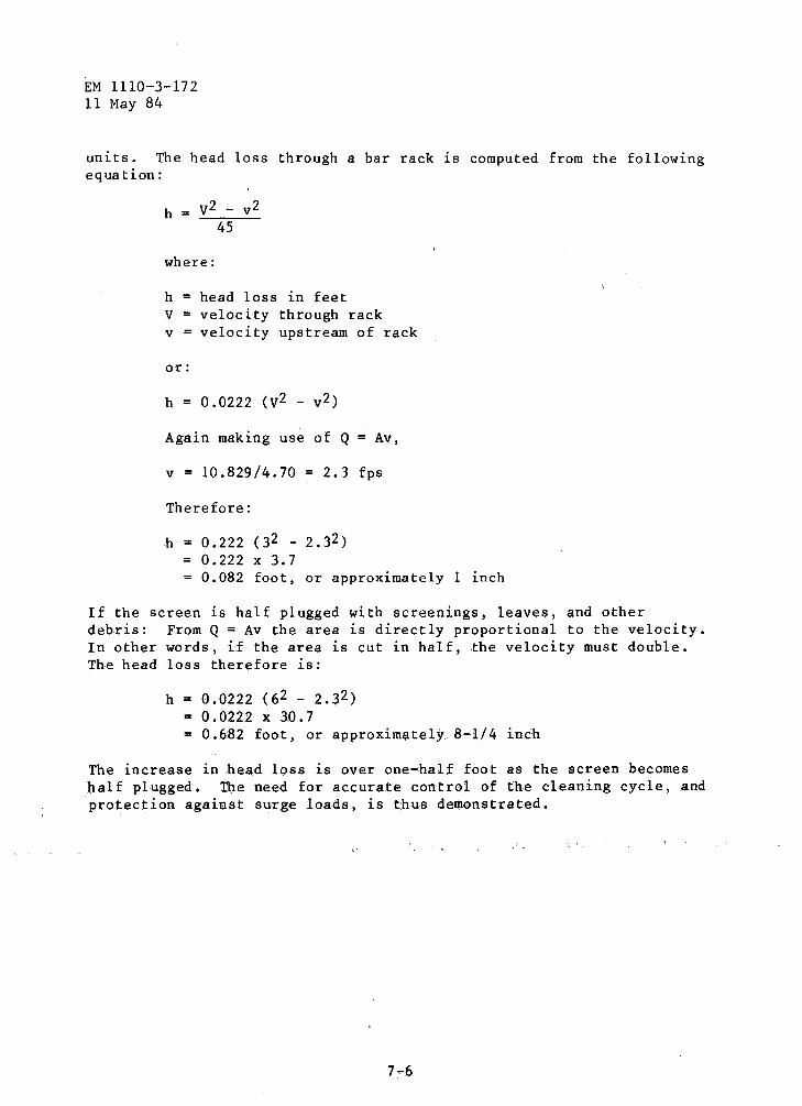
units. The head loss through a bar rack is computed from the following equation:
h = v2 - v2 45
where:
h = head loss in feet V = velocity through rack v = velocity upstream of rack
or:
h = 0.0222 (v2 - v2)
Again making use of Q = Av,
v = 10.829/4.70 = 2.3 fps
Therefore:
h = 0.222 (32 - 2.32) = 0.222 X 3.7
0.082 foot, or approximately 1 inch
If the screen is half plugged with screenings, leaves, and other debris: From Q = Av the area is directly proportional to the velocity. In other words, if the area is cut in half, the velocity must double. The head loss therefore ~s:
h = 0.0222 (62 - 2.32) = 0.0222 X 30.7 = 0.682 foot, or approximate!~ 8-1/4 inch
The increase in head loss is over one-half foot as the screen becomes half plugged. The need for accurate control of the cleaning cycle, and protection against surge loads, is thus demonstrated.
7-6
CHAPTER 8
SEDIMENTATION
EM 1110-3-172 11 May 84
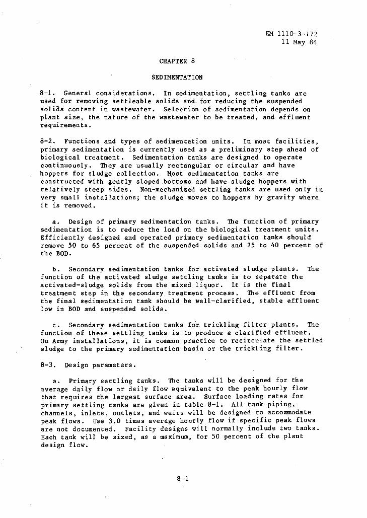
8-1. General considerations. In sedimentation, settling tanks are used for removing settleable solids and, for reducing the suspended solias content in wastewater. Selection of sedimentation depends on plant size, the nature of the wastewater to be treated, and effluent requirements.
8-2. Functions and types of sedimentation units. In most facilities, primary sedimentation is currently used as a preliminary step ahead of biological treatment. Sedimentation tanks are designed to operate continuously. They are usually rectangular or circular and have hoppers for sludge collection. ~ost sedimentation tanks are constructed with gently sloped bottoms and have sludge hoppers with relatively steep sides. Non-mechanized settling tanks are used only in very small installations; the sludge moves to hoppers by gravity where it is removed.
a. Design of primary sedimentation tanks. The function of primary sedimentation is to reduce the load on the biological treatment units. Efficiently designed and operated primary sedimentation tanks should remove 50 to 65 percent of the suspended solids and 25 to 40 percent of the BOD.
b. Secondary sedimentation tanks for activated sludge plants. The function of the activated sludge settling tanks is to separate the activated-sludge solids from the mixed liquor. It is the final treatment step in the secondary treatment process. The effluent from the final sedimentation tank should be well-clarified, stable effluent low in BOD and suspended solids.
c. Secondary sedimentation tanks fo.r trickling filter plants. The function of these settling tanks is to produce a clarified effluent, On Army installations, it is common practice to recirculate the settled sludge to the primary sedimentation basin or the trickling filter.
8-3. Design parameters.
a. Primary settling tanks. The tanks will be designed for the average daily flow or daily flow equivalent to the peak hourly flow that requires the largest surface area. Surface loading rates for primary settling tanks are given in table 8-1. All tank piping, channels, inlets, outlets, and weirs will be designed to accommodate peak flows. Use 3.0 times average hourly flow if specific peak flows are not documented. Facility designs will normally include two tanks. Each tank will be sized, as a maximum, for 50 percent of the plant design flow.
8-1

EM 1110-3-172 11 May 84
Table 8-1. Surface Loading Rates for Primary Settling Tanks
Plant Design Flow mgd
0-0.01 0 .01-0.10 0.10-1.00 1 .00-10.0 above 10.0
Surface Loading Ratel, gpd/square foot Average Flow Peak Flow
300 500 600 800
1,000
500 800
1,000 1,200 1,200
!These rates must be based on the effective areas (figures 8-1 and 8-2).
b. Secondary sedimentation tanks. The sedimentation tanks should be designed for the flow (average or peak) that requires the largest surface area. Surface loading rates for secondary settling tanks are given in table 8-2. Similar to primary tanks, the facility designs will normally include two tanks, each handling SO percent of the design flow.
Table 8-2. Surface Loading Rates fo~ SecondarJ Sedimentation Tanks
Plant Design Flow mgd
0-0.01 0.01-0.1 0.1-1
1-10 above 10
Surface Loading Ratel, gpd/square feet Average Flow Peak Flow
100 300 400 500 600
200 500 600 700 800
!These rates must be based on the effective areas (figures 8-1 and 8-2).
c. General design considerations for all clarifiers.
(1) Detention perfod. Detention time is commonly specified as 2.5 hours for primary tanks serving all types of plants, except when preceding an activated sludge system, wqere detention time is specified as 1.5 hours. Selection of optimum detention time will depend on the tank depth and the overflqw rate. For those Army installations where the contributing population is largely nonresident, the detention period to be used in design of primary settling tanks is 2 hours, based on the average hb~tly rate for the 8-hour period when the maximum number of personnei will be eontributing to sewage flow.
8-2

100 .
80
C( ILl 0:: C(
0:: 60 ILl u:: 0:: C( ...J u
a: U)
40 U)
9 ~ z ~ 0:: ILl Q.
20 \ ~
00 5
I
NOTE:
10 15
EM 111 0-3-1 7 2 11 May 84
For any side-water depth.
-
20 25 30
TOTAL AREA OF RECTANGULAR CLARIFIER, SO FT X 1,000
U. S. Army Corps of Engineers
FIGURE 8-1 EFFECTIVE SURFACE AREA ADJUSTMENTS FOR INLET-OUTLET LOSSES IN RECTANGULAR CLARIFIERS, L:W=4
8-3
EM 1110-3-172 11 May 84
100
80
NOTE: For any side-water depth.
~ Ill a:: 60 ~
a:: !!:! Ll. iE ~ ~ (.)
:!;
rn 40 rn 9 1-ffi (.) a:: Ill A.
20
\ \ "' -......... ~ ""'-40 80 120 160
DIAMETER OF CIRCUI..AR Cl-ARIFIERS, FT
U. s. Army Corps of Engineers
FIGURE 8-2. EFFECTIVE SURFACE AREA ADJUSTMENTS FOR INLET-OUTLET LOSSES IN CIRCULAR CLARIFIERS
8-4
-
200
EM 1110-3-172 11 May 84
(2) Weir rate. The overflow loading on weirs will not exceed 5,000 gpd per lineal foot for plants designed for less than 0.1 mgd, or 10,000 gpd per l~neal foot for plants designed between 0.1 and 1.0 mgd. Weir loading for plants designed for flows of more than 1.0 mgd may be higher, but must not exceed 12,000 gpd per lineal foot. When pumping is required, the pump capacity will be related to tank design to avoid excessive weir loadings.
(3) Typical design. Example A-1 illustrates a typical clarifier design.
8-4. Tank types and design features.
a. General features. Inlets to a settling tank will be designed to dissipate the inlet velocity, to distribute the flow uniformly, and to prevent short-circuiting. The inlet and outlet channels will be designed for a minimum velocity of 2 fps at the average flow rate and will have corners filleted to prevent deposition and collection of solids. Tanks can be circular or rectangular. Side water depths should be a minimum of 6 feet and a maximum of 10 feet. A 2 to 4 foot additional depth should be provided for the sludge blanket. Limit the use of circular clarifiers to applications greater than 25 foot diameter. Where space permits, at least two units will be provided.
b. Rectangular tanks. The minimum length of flow from inlet to outlet of a rectangular tank will be 10 feet in order to prevent short-circuiting of flow in the tank. Tank length-to-width ratio should vary between 3:1 and 5:1. Tanks will be designed with a minimum side water depth of 7 feet, except final tanks in activated sludge plants, which will be designed with a 9-foot minimum depth.
(1) Inlets and outlets. Inlets to rectangular tanks will be designed so as to prevent channeling of wastewater in the tank. Submerged ports, uniformly spaced in the inlet channel, are an effective means of securing distribution without deposition or channeling. Outlet overflow weirs used in rectangular tanks will be of the adjustable type, and serrated weirs are preferred over straight ones. Overflow weirs will be used in most cases.
(2) Collection and removal of scum and sludge. Means for the collection and removal of scum and sludge are required for all settling tanks. The removal of scum from the tank will take place immediately ahead of the outlet weirs and the equipment may be automatic or manual in operation. Provisions will be made for the scum to be discharged to a separate well or sump so that it can be either sent to the digester or disposed of separately. Rectangular tanks will be provided with scum troughs with the crest about 1 inch above maximum water surface elevation. For small installations (less than 1.0 mgd), hand-tilt troughs consisting of a horizontal, slotted pipe that can be rotated by a lever or screw will be used. Proven mechanical scum removal devices
8-5

EM 1110-3-172 11 May 84
such as chain-and-flight types may be used for larger installations. To minimize the accumulation of sludge film on the sides of the sludge hoppers, a side slope of at least 1-1/2 vertical to 1 horizontal will be used. Separate sludge wells, into which sludge is deposited from the sludge hoppers and from which the sludge is pumped, are preferable to direct pump connections with the hoppers.
c. Circular tanks. Circular tank diameters range from 25 to 150 feet. Side-water depths are 7 feet as a minimum, and tank floors are deeper at the center. Adjustable overflow weirs (V-notch type) will extend around the entire periphery of the tank. Scum baffles, extending down to 6 inches below water surface, will be provided ahead of the overflow weir, and the distance betwen scum collection troughs will not exceed 75 feet along the periphery of the clarifier. Circular sludge-removal mechanisms with peripheral speeds of 5 to 8 fpm will be provided for sludge collection at the center of the tank.
8-5. Imhoff tanks. The removal of settleable solids can also be accomplished through the use of Imhoff tanks. Imhoff tanks are simple to operate and do not require highly skilled supervision. There is no mechanical equipment to maintain. Imhoff tanks contain two compartments whereby settling takes place in the upper compartment and sludge digestion occurs in the lower compartment. Therefore, the Imhoff process is a bi-functional process. Settling solids drop through slots into the lower compartment for digestion. The slots are trapped such that gas escaping from the digester zone passes through gas vents but does not filter back through the sedimentation zone. If this gas is not vented around the sedimentation zone, settling characteristics would be disrupted. The settling compartments ofImhoff tanks are normally designed for a surface overflow rate of 600 gpd/square foot at the average rate of flow. Detention times are generally around 2.5 to 3 hours. Average velocities through the settling chamber should not exceed 15 inches per minute. The slot that permits solids to pass through to the digestion compartment will have a minimum opening of 6 inches. For more information on the sludge digestion process of the Imhoff tank, refer to paragraph 12-3.b.(5) of this manual.
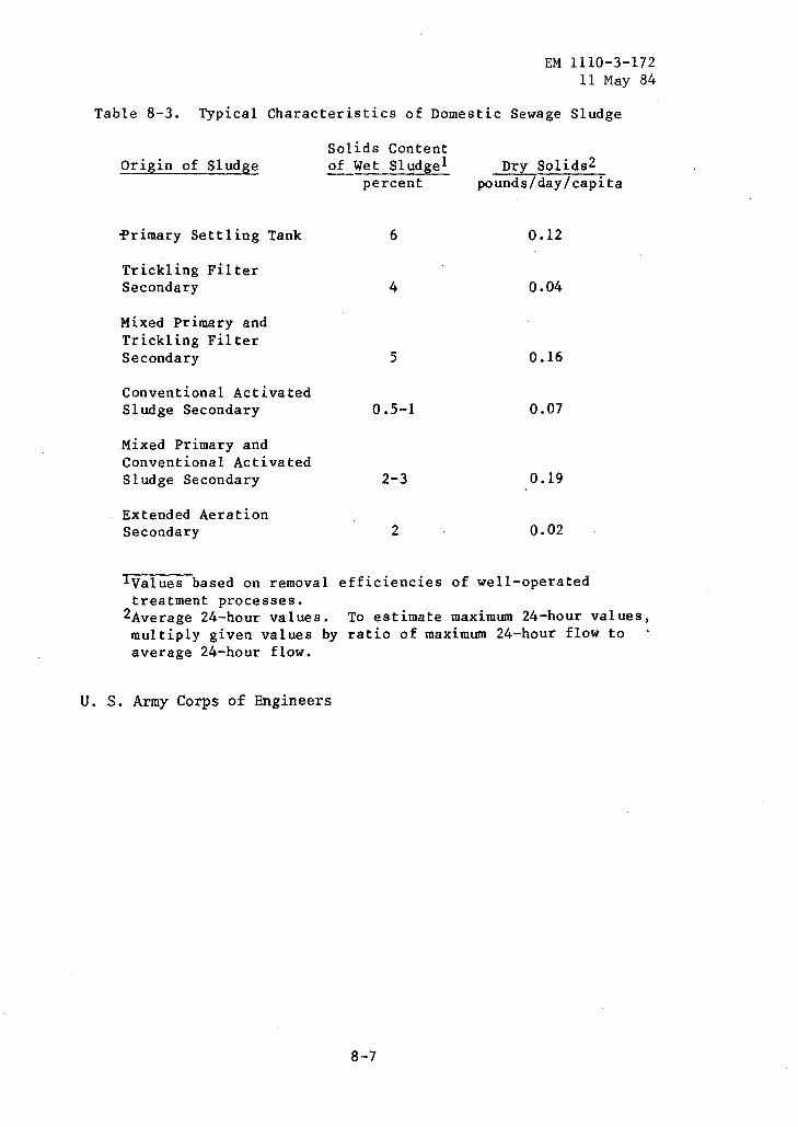
8-6. Sludge charact~ris~ics. Table 8-3 represents typical characteristics of domestic sewage sludge.
8-6
EM 1110-3-172 11 May 84
Table 8-3. Typical Characteristics of Domestic Sewage Sludge
Solids Content Origin of Sludge of Wet Sludgel
percent
~rimary Settling Tank 6
Trickling Filter Secondary 4
Mixed Primary and Trickling Filter Secondary 5
Conventional Activated Sludge Secondary 0.5-1
Mixed Primary and Conventional Activated Sludge Secondary 2-3
Extended Aeration Secondary 2
Dry Solids2 pounds/day/capita
0.12
0.04
0.16
0.07
0.19
0.02
lvalues based on removal efficiencies of well-operated treatment processes.
2Average 24-hour values. multiply given values by average 24-hour flow.
U. S. Army Corps of Engineers
To estimate maximum 24-hour values, ratio of maximum 24-hour flow to
8-7
CHAPTER 9
WASTE STABILIZATION PONDS
EM 1110-3-172 11 May 84
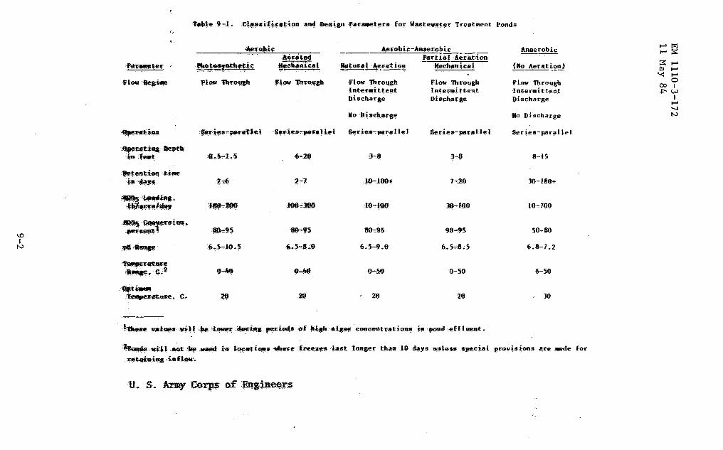
9-1. Waste stabilization pond classification. Waste stabilization ponds are classified as aerobic, aerobic-anaerobic (facultative) and anaerobic (table 9-1).
a. Aerobic ponds.
(1) Photosynthetic wastewater treatment ponds. Oxygen to satisfy the requirements of microorganisms in removing BOD from the wastewater is produced by photosynthesis, utilizing predominately algae, carbon dioxide, and sunlight. The ponds are 6 to 18 inches deep and most oxygen requirements are met by the algae, with some oxygen provided at the gas-liquid interface. BOD of the pond effluent may be higher than that of the influent because algae are present. To achieve the desired level of BOD reduction in such case, it is necessary to remove the algae from the pond effluent. A major disadvantage is the growth of noxious plants that can accumulate floatable debris which can become septic, create odors, and allow pr.opagation of mosquitos.
(2) Mechanically aerated wastewater treatment pond. These are completely mixed wastewater treatment ponds utilizing surface-type aerators, either submerged propeller or turbine-type aerators. The principal source of oxygen is furnished by mechanical aeration rather than by photosynthesis. The solids carry-over from the aeration pond must be removed by a clarification process following treatment in the aeration pond. The concentration of suspended solids in the effluent is approximately equal to that in the pond.
b. Aerobic-anaerobic ponds (facultative).
(1) Natural aeration mode. These are partially mixed wastewater treatment ponds utilizing the natural ambient environment to provide aeration for the wastewater treatment pond. They are divided by loading and stratification into distinct surface and bottom zones,· utilizing aerobic and anaerobic degradation, respectively. Oxygen for aerobic stabilization in the surface layer is provided by photosynthesis and surface reaeration. These are by far the most widely used ponds for sewage treatment. They are operated as flow-through, intermittent discharge or as complete retention of 10 days to 1 year or more. They may be operated as series or parallel ponds, with or without recirculation. With an influent containing 200 mg/1 suspended solids, the effluent can range up to 400 mg/1 because of algae carryover.
(2) Mechanical mode partial aeration. These are partially mixed wastewater treatment ponds, utilizing surface or submerged propeller or
9-1
1.0 I
N
\,.
~~--pth ia .f_t.
~tian·~iiae
i·~-... ~~i~. '1!'6"~·
·T~EC-
~,£.2 ..... ~--.£.
~ni.t:ed
!l!!e~~fi:ic: -~h ... ical
il.,:§.,.l.S 6-20
~~ 2-1
1"'"~ lP0-,000
..,,? 81Hf5
~.~-16~5 6.5-8.0 ... ~
26 .29
~fobic-Anaerobic P~rtial :Aeration
ll!r~uf'al .1\eratioa Mech;anic.al
flow tbrougb lnt~~ittent Discharge
2.0
FlGY 'lbrough In~er~aittent Dischaq~e
7-.20
lf)-.160
0-50
ao
Flo., 'lbrougb IntermiHent ~ischarge
lllo Discharge
Series-parallel
8-15
J0-180+
10-700
50-80
6.8-7.2
6-50
JO
·~ •l'tl .~ ·~ .~ in ~~~i.-s ~e freez'e'S last longer than JO days unles-s spe.cial provisions aFe Jllllde for
·~t~iq inn-.
1-"l?i ....-::;::: :;:::...Ill ..... '< .....
0 001 +:-w
I ..... -...! N
EM 1110-3-172 11 May 84
turbine aerators to provide distribution but not suspension of solids over the pond. The treatment is similar to the natural aeration mode, but with a greater. part of oxygen provided from aeration.
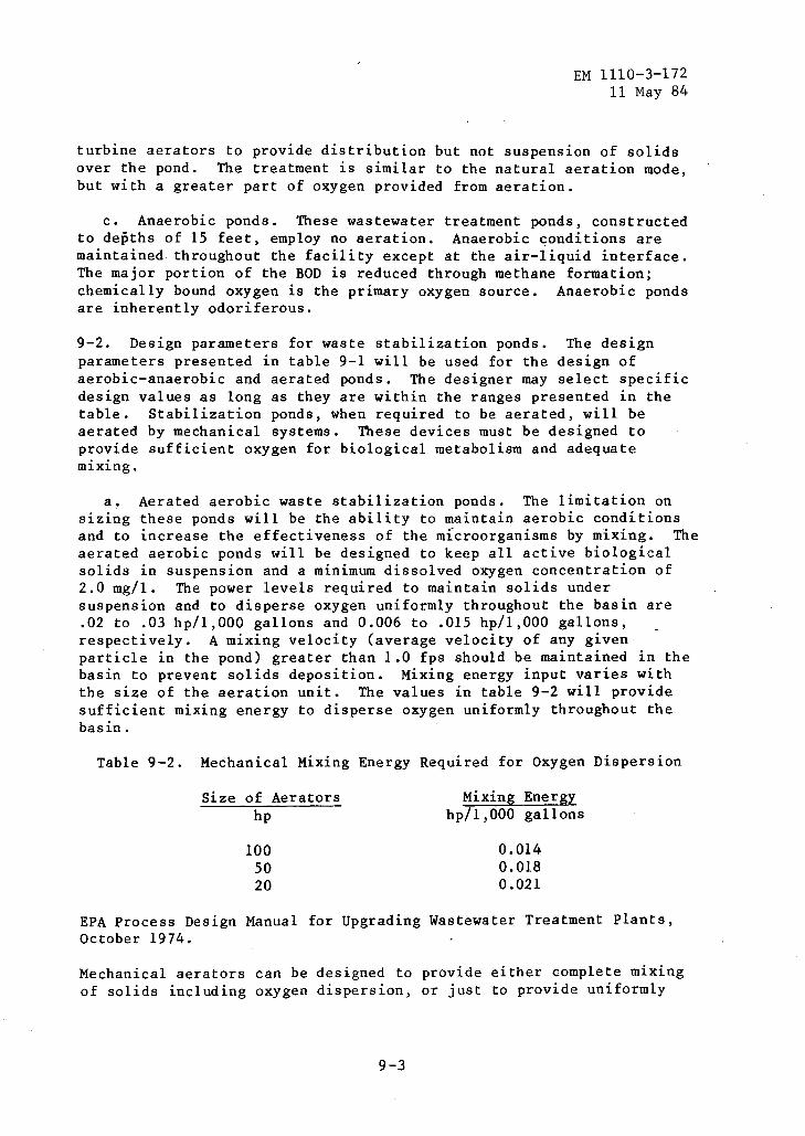
c. Anaerobic ponds. These wastewater treatment ponds, constructed to depths of 15 feet, employ no aeration. Anaerobic conditions are maintained throughout the facility except at the air-liquid interface. The major portion of the BOD is reduced through methane formation; chemically bound oxygen is the primary oxygen source. Anaerobic ponds are inherently odoriferous.
9-2. Design parameters for waste stabilization ponds. The design parameters presented in table 9-1 will be used for the design of aerobic-anaerobic and aerated ponds. The designer may select specific design values as long as they are within the ranges presented in the table. Stabilization ponds, when required to be aerated, will be aerated by mechanical systems. These devices must be designed to provide sufficient oxygen for biological metabolism and adequate mixing.
a. Aerated aerobic waste stabilization ponds. The limitation on sizing these ponds will be the ability to maintain aerobic conditions and to increase the effectiveness of the m1croorganisms by mixing. The aerated aerobic ponds will be designed to keep all active biological solids in suspension and a minimum dissolved oxygen concentration of 2.0 mg/1. The power levels required to maintain solids under suspension and to disperse oxygen uniformly throughout the basin are .02 to .03 hp/1,000 gallons and 0.006 to .015 hp/1,000 gallons, respectively. A mixing velocity (average velocity of any given particle in the pond) greater than 1.0 fps should be maintained in the basin to prevent solids deposition. Mixing energy input varies with the size of the aeration unit. The values in table 9-2 will provide sufficient mixing energy to disperse oxygen uniformly throughout the basin.
Table 9-2. Mechanical Mixing Energy Required for Oxygen Dispersion
Size of Aerators hp
100 50 20
Mixing Energy hp/1,000 gallons
0.014 0.018 0.021
EPA Process Design Manual for Upgrading Wastewater Treatment Plants, October 1974.
Mechanical aerators can be designed to provide either complete mixing of solids including oxygen dispersion, or just to provide uniformly
9-3
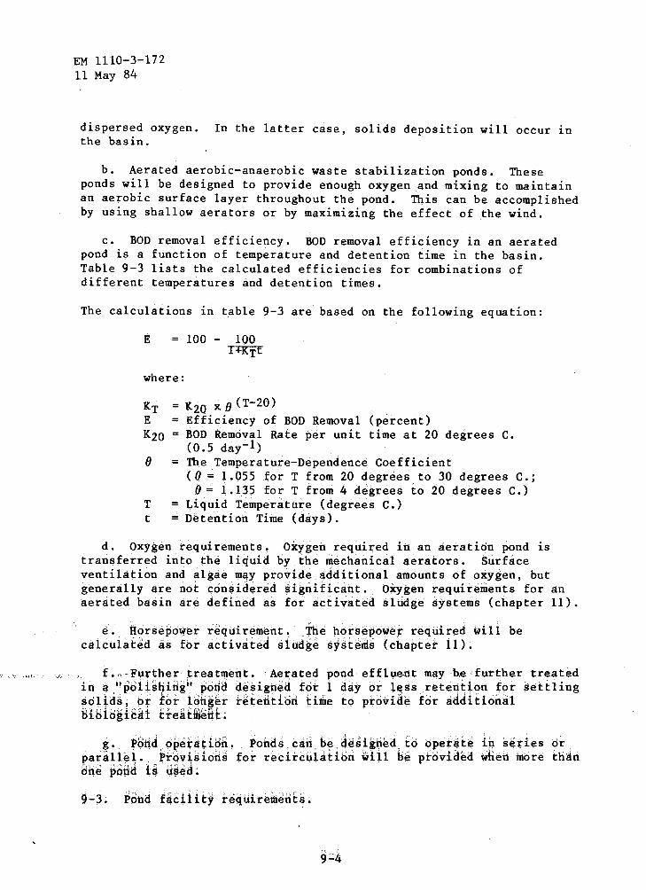
EM 1110-3-172 11 May 84
dispersed oxygen. In the latter case, solids deposition will occur in the basin.
b. Aerated aerobic-anaerobic waste stabilization ponds. These ponds will be designed to provide enough oxygen and mixing to maintain an aerobic surface layer throughout the pond. This can be accomplished by using shallow aerators or by maximizing the effect of the wind.
c. BOD removal efficiency. BOD removal efficiency in an aerated pond is a function of temperature and detention time in the basin. Table 9-3 lists the calculated efficiencies for combinations of different temperatures and detention times.
The calculations in table 9-3 are based on the following equation:
E = 100 - 100 T+KTE
where:
(J
T t
= K20 X (J (T-20) = Efficiency of BOD Removal (percent)
BOD Removal Rate per unit time at 20 degrees C. (0.5 day-1)
= The Temperature-Dependence Coefficient ((J = 1.055 forT from 20 degrees to 30 degrees C.;
(J = 1.135 forT from 4 degrees to 20 degrees C.) = Liquid Temperature (degrees C.) =Detention Time (days).
d. Oxygen requirements. Oxygen required in an aeration pond is transferred into the liquid by the mechanical aerators. Surface ventilation and algae ~ay provide additional amounts of oxygen, but generally are not con$idered significant. O*ygen requirements for an aerated basin are defined as for activated sludge systems (chapter 11).
e. Ho~sepo~er req~irement. ±he horsepower required will be calculated as for activated slud~e systenis (chapter 1i).
f. Further treatmertt. · Aer;ated pond effluent may be further treated irt a 11 pdiisliirig1.' pond deSigned fot i day Or l~ss retention for settling ~olids, or for forig~r feterit:iori time t:o pto~ide for additional Bibiogi&~t Efeatffie&t;
g. ~8rid o~~tatioh. ~orids cari.h~.desik#~d. t:o opE!r4tE! in s~ries or parallel.. Pf6v~sions for recirculation ~ill be provided wben more t:han 8ne pdrid is u~aa.
9-3. Pbriq £aciiity require~ents;

EM 1110-3-172 11 May 84
Table 9-3. BOD Removal Efficiencies for Aerated Wastewater Treatment Ponds
Percent BOD Removal for Various Detention Times in Days
TemEerature (T-20) K20 2 3 4 6 8 10 -degrees C.
4 0.1318 0.066 12 16 21 28 35 40
6 0.1698 0.085 15 20 25 34 40 46
8 0.2188 0.109 18 25 30 40 47 52
10 0.2819 0.141 22 30 36 46 53 59
12 0.3631 0.181 27 35 42 52 59 64
14 0.4678 0.234 32 41 48 58 65 70
16 0.6026 0.301 38 47 55 64 71 75'
18 0. 7763 0.388 44 54 61 70 76 80
20 1.000 0.500 50 60 67 75 80 85
22 1.1130 0.557 53 63 69 77 83 85
24 1.2387 o. 619 55 65 71 79 83 86
26 1.3786 0.689 58 67 73 79 85 87
28 I. 5343 0.767 61 70 75 82 86 88
30 1.7076 0.854 63 72 77 84 87 90
32 1.9005 0.950 66 74 79 85 88 90
34 2.1152 1.058 68 76 81 86 89 91
36 2.3542 1.177 70 78 82 88 90 92
38 2.6201 1.310 72 80 84 89 91 93
u. S. Army Corps of Engineers
9-5

EM 1110-3-172 11 May 84
a. Inlet. Inlet into the pond will be by a single inlet pipe, with discharge into a circular, deeper, sludge storage zone below the bottom of the normal pond. Discharge will be onto a concrete splash pad or diffusion block. The sludge storage section should have a maximum diameter of 200 feet, but not less than 50 feet, with a center depth not less than 1.0 foot, below the normal bottom elevation, with inlet pipe discharge at the center of the sludge storage section. The discharge will be located near the leeward side of the pond or at right angle to the prevailing winds near the end most remote from the outlet structure. The inlet pipe from point of discharge to the outer berm of the dike will be on a level grade at a depth sufficient to provide adequate freeze protection when the pond is at minimum operating level at maximum freeze depth. A standard manhole will be placed in the outer berm of the pond dike on the inlet pipe. The manhole will be utilized for rodding the inlet pipe or surge pumping through the discharge to maintain a clean open inlet. The splash block, or discharge diffusion block,· will be so designed that scouring of the bottom will not occur with the above operations.
b. Outlet structures. Outlet structures will permit lowering the water level at a rate of not less than 1.0 foot per week while the pond is receiving its normal flow. Provisions will be made for complete drainage of the pond. Outlet structures will be located on the windward side of the dike at a point most remote from the inlet, will be large enough to permit easy access for normal maintenance, and will provide complete draining of the pond. The outlet from each cell should have the capacity to change the depth from maximum to minimum operating depth in 6-inch increments to give operational flexibility as well as a drain for the entire pond. The structure will be designed to minimize velocities at any point of withdrawal. In small ponds with normal discharge of 50,000 gpd or less, a large pipe with adjustable sections is adequate. Outlet velocity across the pipe entrance must be kept under 0.5 fps. The provision will be met with an adjustable weir in ponds with discharge in excess of 50,000 gpd. There will be three sets of baffles concentrically around the outlet structure(s). The first baffle will extend 3 to 5 feet around the outlet structure, with the baffle extending at least 6 inches to 1 foot above the highest water level and down to within l foot of the bottom of the pond. The second baffle is set in the bottom of the pond and extends to within 6 inches of the lowest anticipated operating level. The third baffle is the same as the first. When design includes siphoning, outlet line(s) wi 11 be vented.
c. Dikes. Dikes will have a minimum top width 10 feet, a minimum freeboard at 2 feet above high water level, and side slopes of a minimum 3 horizontal to 1 vertical for inside and outside slopes. fk•tcrl;;;niltion of slope will be based on natural angle of repose of the .':oi 1, \.ength of open water ~•lope protect-ion. pr:ovidc~d. Ann soil , h,:,r.:•r:cri;:;ti<· TJikes v.r; ll compActed '' 9() percpn; •.·i 'na·imum (!l' l.t t optiw.lHH morstur{ content od se·;:.~1c·d dg.~1Jost i r:':p:lg(.'·, An
9 . {]

EM 1110-3-172 11 May 84
excavated drain will be provided at the toe of the exterior slope to convey seepage water, over-topping loss, or spillage due to dike failure to the receiving watercourse for the waste stabilization pond discharge. Protection from wind and water erosion will be provided as needed.
d. Bottom. The bottom will be as level as practicable with variations not exceeding 6 inches from the designed bottom elevation. This does not apply to the dished area around the inlet, covered by paragraph 9-3.a. The bottom will be cleared, grubbed, and sealed to prevent loss of liquid through excess seepage. If ground water protection is a requirement or desirable, then a liner would be necessary depending on soil permeability. If the soil permeability is lo-7 em/second or better, a liner would not be required. For lesser permeabilities, a water barrier of some kind should be provided. Some acceptable lining materials are various synthetics, bentonite, clay, or pavement materials such as concrete or asphalt.
e. Surface runoff control. Surface runoff will be excluded .from wastewater treatment ponds. Intercepting drains, diversion ditches, and/or dikes will be constructed as required to comply with this requirement. When surface drainage must be rerouted to meet the requirement, rerouted drainage will be routed to the original drainage course to the maximum extent possible.
f. Fencing and access. The entire wastewater treatment ponds area will be provided with a locked security fence that will have a double wide gate for vehicular access. A gravel road not less than 10 f~et
wide will be provided through this gate and around the new dike.
g. Flow operation modes. In no case will a raw wastewater treatment pond have less than two cells. Operation will normally be in series, with piping flexibility permitting parallel or series operation, recirculation if desired, and isolation and removal from service of any unit without interference in operation of any other unit. The maximum design BOD loading rate to each pond cannot be exceeded for any mode of operation.
9-7

CHAPTER 10
TRICKLING FILTER PLANTS
EM 1110-3-172 11 May 84
10~1. General considerations. Trickling filter plants have been justified by their low initial cost, low operating and maintenance costs, and simplicity of operation. Although the effluent from trickling filter plants of earlier design was of poorer quality than that from activated sludge plants, the performance of trickling filters designed more recently is comparable to that of activated sludge plants. Both processes offer certain advantages, with trickling filters providing good performance wi.th minimal operator care and few, if any, energy requirements. Trickling filters are classified as low-rate or high-rate, and according to the organic loading applied. Another classification is shallow and deep filters; usually, filters less than 7 feet deep are considered to be shallow filters; those with a greater depth are considered to be deep trickling filters. Filters are also classified according to the type of media utilized, i.e., rock or synthetic media.
10-2. Design basis and criteria. The designer will provide preliminary and primary treatment ahead of the filters, and circular or rectangular settling tanks with mechanical sludge removal equipment following the filters. Design criteria for settling tanks are in chapter 8. Table 10-1 gives design data for the trickling filter process. The designer normally will use the average of the hydraulic or organic loading ranges presented in table 10-1 for the design of each filter class, unless special conditions warrant the use of values other than the average.
a. Filter depth. Stone media trickling filters will be designed with depths of 5 to 7 feet for low-rate and depths of 3 to 6 feet for high-rate applications. Synthetic media manufacturers recommend depths of 10 to 40 feet for columnar or stacked module media. Randomly placed polypropylene media filters are designed within the depth ranges of the low-rate filters. The deeper trickling filters can improve nitrification potential and can be used as the second stage in two-stage biological system designs for nitrification.
b. Recirculation. This is an accepted method of increasing the BOD removal efficiency of high-rate trickling filter processes. Figure 10-1 shows acceptable recirculation systems for single-stage and two-stage trickling filters treating domestic wastewater. Table 10-2 lists recommended recirculation rates for high-rate filters. Whether to use recirculation, and the amount to be recycled when used, are matters of economics which may involve either first cost or annual costs of various designs providing equal treatment. Unless other conditions control, recirculation should provide continuous dosing at a minimum surface application rate of 10 mgad. In flow diagrams B, C, and D (figure 10-1) fluctuati~ns in the organic loading applied to the
10-1

1--h a. I
N"
Table 10-l. Desigu Data and Information for Trickling Filter Processes
------------~F=i=l=t=er Classification
Item
ltyprauHc: loadingl gpd/.s~ttJaire foot
(}£ggwic~ load.ing2 lb's 800/day/l,OOO'.cubic feet
Temperature Coefficient·, Q.
Depth:, fee-t
Re.cir.cu4a1:ion· ratio, R/Q.
Dosing intervaJ.•
Sloughing,
Nhri f ication
Low-Rate
25'-90
5-20
75-85
1.02-1.06
5-7
NOlle
Rock, slag:; random-placed· plastic5
Not more· than 5 minutes
Intermittent
Usually higher nitrified·
230-690
30-60
70-85
1.02-1.04
3-6
1: l to 4: 13
Rock, slag·, plastic4,5
Continuous
Continuous
Not fully nitrified
IHydraul1c loading range rat~s based ·on plant average flqw; expressed as gpd per square foot.
2L.>adingc.range· (not including recirculation) to produce highest quality effluent after settling.
3Refer to paragraph 10-2 for· dlt&igo··recirculation rate.
4stacke<l• plastic media· may •. be· used<when· instal led· according·. to manufacturer's rec0111111endat ions at proper depth.
5Rand0Jif:fplaced plastic media:.
U. S. Army Corps of Eng;ineers
1-' t:r:l 1-' :z; :z; 1-' Pl 1-'
"-<: 1-' 0
00 ! ~ w
I 1-' -.1 N

SINGLE-STAGE R
EM 1110-3-172 11 May 84
F
G
H
LEGEND
s R
c:J 0
em ~.
A
o*
TWO-STAGE
Sludge Return Recirculated Flow Primary Clarifier Trickling Filter Intermediate Clarifier Final Clarifier
+
+
t •
:1-
t ... ....
t .. + l ..
Reprinted with Permission From "Sewage Treatment Plant Design" Manual of Pr~ctice No. 8, Water Poll. Control Federation, Washington, D.C. Manual of ENG. Practices No. 36, Amer. Soc. Civil Engr., New York, NY (1959)
* PREFERRED FOR ARMY APPLICATIONS
+ NOT TO BE USED WHEN NUTRIENT REMOVAL IS REQUIRED.
FIGURE 10-1. COMMON FLOW DIAGRAMS FOR SINGLE AND TWO-STAGE HIGH-RATE TRICKLING FILTERS
10-3
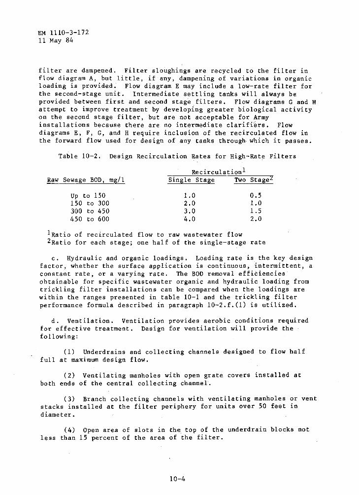
EM 1110-3-172 11 May 84
filter are dampened. Filter sloughings are recycled to the filter in flow diagram A, but little, if any, dampening of variations in organic loading is provided.' Flow diagram E may include a low-rate filter for the second-stage unit. Intermediate settling tanks will always be provided between first and second stage filters. Flow diagrams G and H attempt to improve treatment by developing greater biological activity on the second stage filter, but are not acceptable for Army installations because there are no intermediate clarifiers. Flow diagrams E, F, G, and H require inclusion of the recirculated flow in the forward flow used for design of any tanks through which it passes.
Table 10-2. Design Recirculation Rates for High-Rate Filters
Raw Sewage BOD, mg/1
Up to ISO ISO to 300 300 to 450 4SO to 600
Recirculation! Single Stage Two Stage2
1.0 2.0 3.0 4.0
0.5 1.0 1.5 2.0
!Ratio of recirculated flow to raw wastewater flow 2Ratio for each stage; one half of the single-stage rate
c. Hydraulic and organic loadings. Loading rate is the key design factor, whether the surface application is continuous, intermittent, a constant rate, or a varying rate. The BOD removal efficiencies obtainable for specific wastewater organic and hydraulic loading from trickling filter installations can be compared when the loadings are within the ranges presented in table 10-1 and the trickling filter performance formula described in paragraph 10-2.f.(l) is utilized.
d. Ventilation. Ventilation provides aerobic conditions required for effective treatment. Design for ventilation will provide the following:
(I) Underdrains and collecting channels designed to flow half full at maximum design flow.
(2) Ventilating manholes with open grate covers installed at both ends of the central collecting channel.
(3) Branch collecting channels with ventilating manholes or vent stacks installed at the filter periphery for units over 50 feet in diameter.
(4) Open area of slots in the top of the underdrain blocks not less than 15 percent of the area of the filter.
10-4

EN 1110-3-172 11 May 84
(5) Peripheral duct (or channel) interconnecting vent stacks and collecting channels.
(6) One square foot of gross area of open grating in the ventilating manholes and vent stacks for each 250 square feet of filter surface.
(7} When the trickling filter is constructed with top of media or distributor arms at or near grade, with underdrain system more than 3 feet below grade, or when normal climatic conditions do not include adequate air movement, ventilation shafts will be provided.
e. Temperature. The performance of trickling filters will be affected by temperature changes in· the wastewater and filter films. Filter efficiency changes attributed to temperature variations are expressed by the following formula.
ET = E20 x 0 (T-20)
Note: For values of o(T-20) when 0 = 1.035 see appendix B.
where:
ET = BOD removal efficiency at T degrees c. E2o = BOD removal efficiency at 20 degrees C. 0 = Constant equal to 1.035 T = Wastewater temperature, degrees c.
The temperature formula will be used to correct the filter performance predicted by the NRC design formula. In areas that experience prolonged cold and/or icing, wind breaks or dome covers for trickling filters to prevent freezing problems will be considered.
f. Plant efficiencies. Performance efficiencies, given as BOD removal, of single-stage and two-stage filters, are to be estimated using formulas in the following section,
(1) National Research Council (NRC) formulas. The NRC formulas will be used to design all stone-media trickling filters for Army installations. NRC developed the following formulas for predicting the stone-media trickling filter performance at 20 degrees C.
Fir~t or Single Stage:
100 1/2
1 + 0.0085(W/VF)
10-5

EM 1110-3-172 11 May 84
Second Stage: (Includes intermediate clarifier)
100 1/2
1 + 0.0085 (W'/V'F) 1 - E1
where:
E1 Percent BOD removal efficiency through the first or single-stage filter and clarifier.
W = BOD loading (pounds/day) to the first or single-stage filter, not including recycle.
V Volume of the first filter stage (acre-feet) F = Recirculation factor for a particular stage, where:
F = 1 + R
(1 + 0 .1R)2
R Recirculation ratio = Recirculation flow Plant influent flow
E2 = Percent BOD removal through the second-stage filter and clarifier.
W' = BOD loading (pounds/day) to the second-stage filter, not including recycle.
V' = Volume of the second filter stage (acre-feet)
A sample problem utilizing the NRC formula is presented in appendix A.
(2) Other design formula. Although the NRC formula is required for design of stone-media filters, the following formula is appropriate for stacked synthetic media filters.
Le = exp Lo
where:
e = Lo = Le = D = exp=
Q =
n =
Temperature constant equal to 1.035 BOD of primary effluent (not including recirculation) BOD remaining, i.e., effluent BOD Depth of filter Symbol designating that what follows is the exponent to which the natural logarithm base, e, is to be raised Hydraulic loading (not including recirculation), gpm/square foot of cross-sectional area Exponent characteristics of filters (use 0.67 for synthetic media)
10-6

EM 1110-3-1 i2 11 May 84
K2o = Treatability constant (use 0.088 for plastic media treating Army installation wastewaters).
A sample problem, utilizing this formula for a synthetic media design, is pres~nted in appendix A. Unless particular filter media usage or unusual design conditions necessitate the use of one of these formulas, the NRC formulas will be used in design of Army facllltles.
10-3. Nltrlflcatlon in trickling filters. The development and maintenance of nitrifying organisms in trickling filter systems depend mainly on the organic loading and wastewater temperature. Generally, nitrification occurs best at low BOD loadings (less than 5 pounds BOD/day/1,000 cubic feet) and high wastewater temperature (20 degrees C. or higher). The degree of nitrification in trickling filters improves as the volumetric BOD loading is reduced. Depending on effluent requirements, ln colder climates existing trickling filter plants will be modified to achieve a high degree of nltrlflcatlon year-round, or only during the warmer months of the year. Year-round nltrlflcatlon facllltles will be designed for the lowest dally average wastewater temperatures experienced In the winter months. In this Instance, the required filter volume will be greater than that required for seasonal nitrlflcatlon and will require at least two-stage treatment. Trickling filters Intended to proylde 80 to 90 percent nitrification will be designed at a hydraulic loading of SO gpd/square foot and an organic loading of 4 pounds BOD/day/1,000 cubic feet.
10-4. Hydraulic components.
a. Influent distributors. Rotary reaction distributors consisting of two or more horizontal pipes supported by a central column are available for dosing filter beds ranging from 20 to more than 200 feet in diameter. Distributors will be sealed by pressurized oil, neoprene gaskets, or air-gap "non-seal" methods. Hydraulic head requirements for distributors vary approximately as the square of the Influent flow, with the hydraulic gradient usually 12 to 24 inches above the center line of the distributor arms at minimum flow. Distributor design must provide: (a) a means for correcting allnement, (b) adequate structural strength, (c) adequate pipe size to prevent velocities in excess of 4 fps at maximum flow, (d) bearings, (e) drains for dewatering the inflow column, and (f) pipe and openings at the end of each arm for ease of removing lee buildups during winter operation. A minimum clearance of 6 inches between media and distributor arms will be provided. Motor-driven rotary distributors will be used only if the minimal hydraulic head to drive the distributor is not available. Positive drive will be provided by a totally enclosed electric motor and gear arrangement.
b. Dosing siphons. Wastewater may be applied to the filters by pumps, by gravity discharge from preceding treatment units when
10-7
EM 1110-3-172 11 May 84
suitable flow characteristics have been developed, and by siphons. Frequently during the day the flow will be less than the minimtn11 set by the distributor. If this is the case, a dosing tank and alternating siphons will be required for each filter unit. Each siphon will have a dosing tank with a volumetric capacity equal to the average flow rate for a 4-minute period so that dosing is nearly con.tinuous.
c. Head loss computations. The net available head on the horizontal center line of the distributor arms will be calculated by deducting the following applicable losses from the available static head:
(1) Entrance loss from the primary settling tank.
(2) When using-dosing siphons: the drop in tank level dosing as distributor pipes are filled, the friction losses in the siphon itself, and the velocity head imparted from the siphons.
(3) Friction losses in piping and fittings.
( 4) Loss through dis tributor column rise and center port.
(5) Friction loss in distributor arms and velocity head of discharge through nozzles necessary to start reactor-type rotary distributors in motion. The hydraulic head requirements of distributors are specified by the manufacturers. The major head loss is the elevation difference between the distributor arms and the lowest water surface in the main underdrain channel. Approximately 8 feet of head is lost in a 6-foot deep filter. Detailed computations and charts for head loss in pipes are presented in EM lll0-3-174.
10-5. Other filter components. Table 10-3 gives a list of other components normally associated with trickling filters anq for which design requirements are specified. 'l'rickl ing filter design must include provisions for flooding the filter and the filter walls, ~nd appurtenances must be able to structurally withstaqd the resulting hydrostatic pressure forces when the filter is floodeq. In northern regions that are subject to extreme and/or prolonged freezing conditions, including high winq chill factors, design considerations must be givep to providing filter dome covers .or wind breaks. Figur~ 10-2-is ~·sectional view o'f a trickling filter. ·
10-8
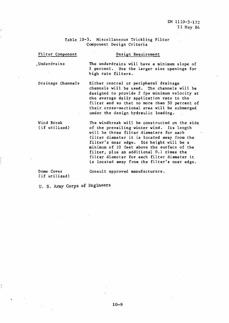
EM 1110-3-172 ·11 May 84
Table 10-3. Miscellaneous Trickling Filter Component Design Criteria
Filter Component
.Underdrains
Drainage Channels
Wind Break (if utilized)
Dome Cover (if utilized)
Design Requirement
The underdrains will have a minimum slope of 1 percent. Use the larger size openings for high rate filters.
Either central or peripheral drainage channels will be used. The channels will be designed to provide 2 fps minimum velocity at the average daily application rate to the filter and so that no more than 50 percent of their cross-sectional area will be submerged under the design hydraulic loading.
The windbreak will be constructed on the side of the prevailing winter wind. Its length will be three filter diameters for each filter diameter it is located away from the filter's near edge. Its height will be a minimum of 10 feet above the surface of the filter, plus an additional 0.1 times the filter diameter for each filter diameter it is located away from the filter's near edge.
Consult approved manufacturers.
u. s. Army Corps of Engineers
10-9

EM 1110-3-172 11 May 84
F+GYEE lQ-2~ +~fCK~I~~ FILTER COMPON~NTS lP-Ul
• ' 1''-'

CHAPTER 11
ACTIVATED SLUDGE PLANTS
EM 1110-3-172 11 May 84
11-1. General considerations. The activated sludge process is a biologjcal treatment process in which a mixture of wastewater and microorganisms is agitated and aerated. The activated sludge mixed liquor is subsequently separated by sedimentation, and the sludge is returned to the process, with some withdrawn as waste sludge. This chapter presents the different modifications of the conventional activated sludge process, including general bases for design, methods of aeration, and design factors for aeration tanks, final sedimentation units, and sludge handling systems. All designed processes will include preliminary treatment consisting of screening as a minimum.
a. Basic process. · Basically the activated sludge process uses microorganisms in suspension to oxidize soluble and colloidal organics to carbon dioxide and water in the presence of molecular oxygen. During oxidation, portions of the organic material are synthesized into new cells. Oxygen is required to support the oxidation and synthesis reactions. The solids generated must be separated in a clarifier for recycle to the aeration tank; the excess sludge is withdrawn for treatment and disposal.
b. Modifications of the process. Modifications to the conventional activated sludge process include step aeration, contact stabilization, plug flow, completely mixed, and extended aeration systems.
11-2. Activated sludge processes. The two basic reactor types .are plug-flow and complete-mix models. In plug flow, fluid particles pass through the tank and are discharged in the same sequence in which they enter. Complete mixing occurs when the particles entering the tank are immediately dispersed throughout the tank. Because of the continuous mixing, completely mixed units are less susceptible to upsets caused by toxic chemicals or shock loadings than are plug-flow units.
a. Conventional activated sludge. In a conventional (plug-flow) activated sludge plant, the primary-treated wastewater and acclimated microorganisms (i.e., activated sludge or biomass) are aerated in a basin or tank. After a sufficient aeration period the flocculent activated sludge solids are separated from the wastewater in a secondary clarifier. The clarified wastewater flows forward for further treatment or discharge. A portion of the clarifier underflow sludge is returned to the aeration basin for mixing with the primary-treated influent to the basin, and the remaining sludge is returned to head of plant. The portion recirculated is determined on the basis of the ratio of MLVSS to influent wastewater BOD which will produce the maximum removal of organic material from the wastewater. Recirculation varies from 25 to 50 percent of the raw wastewater flow,
11-1
EM 1110-3-172 11 May 84
depending on treatment conditions and wastewater characteristics. A flow schematic for ~ conventional activated sludge plant is shown in figure 11-la.
b. Step aeration. In this process, the influent wastewater is introduced at various points along the length of the aeration tank. Sludge return varies between 25 and 50 percent. Aeration or the oxygen requirement during step aeration (3 to 7 hours) is about half that required for the conventional process. This results from a more efficient biomass utilization in the aeration basin, allowing organic loadings of 30 to 50 pounds BOD per 1,000 cubic feet per day, as compared to loadings of 30 to 40 pounds BOD per 1,000 cubic feet per day permitted for conventional syst~ms. A flow schematic for a step aeration activated sludge plant is shown in figure 11-lb.
c. Contact stabilization. The contact stabilization activated sludge process is characterized by a two-step aeration system. Aeration of short duration (1/2 to 2 hours) is provided in the contact tank, where raw or primary settled wastewater is mixed with the activated sludge in the contact tank. The effluent from the contact tank is then settled in a final settling tank. The settled activated sludge to be recycled.from the final clarifier is drawn to a separate reaeration or stabilization basin for 3 to 6 hours of aeration time. It is then returned to the contact aeration basin for mixing with the incoming raw wastewater or primary settled effluent. In addition to a shorter wastewater aeration time, the contact stabilization process has the advantage of being able to handle greater shock and toxic load~ngs than conventional systems because of the buffering capacity of the biomass in the stabilization tank. During these times of abnormal loadings, most of the activated sludge is isolated from the main stream of the plant flow. Contact stabilization plants will not be used unless daily variations of hydraulic or organic loadings routinely exceed a ratio of 3:1 on consecutive days. A flow schematic for a contact stabilization activated sludge plant is shown in figure 11-lc.
d. Completely mixed activated sludge. In the completely mixed process, influent wastewater and the recycled sludge are introdu.ced uniformly through the aeration tank. This allows for uniform oxygen demand throughout the aeration tank, and adds operational stability when treatia.g shock loads. Aeration time ranges b~tween 3 and 6 hours. Recirculation ratios in a completely mixed syst~m will range from 50 to 150 .percent. A flow schematic for a completely mi:x;ed activated sludge .plant is shown in figure 11-ld.
e. Extended aeration. Extended aeration activated sludge .plants are designed to .provide an aeration .period of from 18 to 36 hours for low organic loadings of less than 20 .pounds BOD per 1,000 cubic feet of aeration tank volume. This approach, which is to be used for treatment . .plants q,.f less tl~oan 0 .• 1 mgd capacity, redu.ces. the amqunt of. sludge
11-2

EM 1110-3-172 11 May 84
RAW PRIMARY \VASTEWATER---..~ HB~MENTA-
c..:l 0 ~ .....:l C/)
C/) C/)
SLUDGE TO IGESTER
AERATION ::)
( TANK
6-8 HOURS -;)
(:DETENTION
FINAL CLARIFIER
"" ~~----------~~~~~~~~~~~~ ""
FIGURE 11-1a CONVENTIONAL ACTIVATED SLUDGE FLOW DIAGRAM
RAW WASTEWATER
AERATION TANK 3-7 HOURS DETENTION TIME
t 1 r
PRIMARY FINAL SEDIMENT A- _.. ...... CLARIFIER TION
• SLUDGE TO 4f 4 DIGESTER
LRETURN AND EXCESS SLUDGE EXCESS SLUDGE
FIGURE 11-lt STEP AERATION FLOW DIAGRAM
U. S. Army Corps of Engineers
FIGURE 11-1. ACTIVATED SLUDGE FLOW DIAGRAMS
11-3
f--
FINAL EFFLUENT
FINAL EFFLUENT

EM 1110-3-172 11 May 84
RAW WASTEWATER
PRIMARY SEDIMENT A-TION
• SLUDGE TO DIGESTER
CONTACT TANK 0.5-2.0 HOURS DETENTION
....... STABILIZATION ~I< 3-6 HOURS TAN !DETENTION
FINAL CLARIFIER f--.+.
FINAL EFFLUENT
RETURN AN
RETURN EXCESS SL
SLUDGE,
EXCESS SLUDGE
•
D UDGE
FIGURE ll-lc CONTACT STABILIZATION FLOW DIAGRAM
RAW WASTEWATEl\.
RIMARY EDIMENTA
TION
SLUDGE TO DIGESTER
EXCESS SLUDGE
AERATION TANK FINAL "-__ .,_FINAL CLARIFIER EFFLUENT
LUDGE
FIGURE ll-ld COMPLETELY-MIXED FLOW DIAGRAM
U. S. Army Corps of Engineers
FIGURE lJ,-1. A,CTlVATED SLUDGE FLOW DIAGRAMS (CONTINUED)
11-4

EM 1110-3-172 11 May 84
being wast~d for disposal. It will be considered as an option in larger plants.
f. Oxidation ditch process. The oxidation ditch process is an attractive alternative for Army application. The process is simple to operate and maintain and performs reliably without highly skilled operators. There are few moving parts which can wear out or fail. By their very nature, oxidation ditches provide flow equalization -- an important requirement for Army plants. They need no primary clarifier and produce a stabilized sludge which requires no further treatment (i.e., no anaerobic digester). Despite their simplicity, oxidation ditches are a flexible technology and can be configured not only for BOD oxidation, but also for nitrification and denitrification. Oxidation ditches have lower capital and operation and maintenance cost~ t1an any other biological process for the capacity range within which 75 percent of all Army plants fall.
(1) An oxidation ditch is a modification of the activated-sludge treatment process. It is commonly operated in an extended aeration mode, although conventional activated-sludge treatment is also possible. Typical oxidation ditch treatment systems consist of a single, closed-loop channel 4 to 8 feet deep, with 45 degree sloping side walls.
(2) Some form of preliminary treatment, such as screening, normally precedes the oxidation ditch process. Primary clarification is usually not done. Single or multiple mechanical aerators are mounted across the channel, in a fixed or semi-fixed floating position. Horizontal-brush, cage, or disc-type aerators or vertical-shaft aerators designed for oxidation ditch applications are normally used. The aerators provide mixing and circulation in the ditch, as well as sufficient oxygen transfer. Besides BOD removal, a high degree of nitrification may occur without special modifications because of the ditch's long detention time (normally 16 to 24 hours) and the long solid retention time (10 to 50 days). Secondary clarification is provided in a separate clarifier, although an intrachannel clarification modification may be used, if feasible.
(3) Ditches may be built of various materials, including concrete, shotcrete, asphalt, or impervious membranes. Concrete is the most common. Ditch loops may be oval or circular, although "ell" and "horseshoe" configurations have been used to maximize land usage.
11-3. Design basis and criteria.
a. Design formulation. Table 11-1 provides design criteria. Standard design values provided hereinafter will be used.
11-5

EM 1110-3-172 11 May 84
Table 11-1. Design Criteria for Activated Sludge Modifications
Process Type Desi~n Flow Aeration Period _JQD Loading mgd hours pounds/1,000
cubic feet
Conventional below 0.5 7.5 30
'' 0.5 to 1.5 7.0 35
above 1.5 6.0 40
Step Aeration below 1.5 6.0 30
above 1.5 5.0 50
Complete Mix All 6.0 50
Extended Aeration below 0.1 18 to 36 <20
Contact Stabilization below 0.5 2.0 contact 30 5.0 reaeration
0.5 to 1.5 1.5 contact 40 5.0 reaeration
above 1.5 1.0 contact 50 4.0 reaeration
b. Aeration period. The required aeration period is a function of influent characteristics, mixed liquor volatile suspended solids concentration; and BOD removal rate. The design aeration period is the hydraulic detention t'fme and is equal to the volume of the reactor divided by t:he design' influent wafitewater flow rate. '
< '. \ ' '
c. Organic loadings. +P.e oq~a11ic loadings are tabu~a~ed in tab e 11-l fot' th~ 'deSl.g:ri' of specl.fic' activateq s+udg~ proces~es anq plan Sl.z~s·~ .·l.i ·! i:'' :;, \ i· ·J,' .. ) ..,,q;!:.,. (:-.!\.·: .. ~- ,,,:, }.;,.,
, . cL ~~~1~~ P:f~~~~ft?~·. ~*ces~ ~fudgt; Pf'?.qt1c~Jo~ ,in_,~n,, .. ac~iva~ed sludge plant w1ll l:>e est1mated to be between 0.4 and 0. 7 pound y$S}pouri4s"~9P'i-~move4, ·for rwrnuil organic +o~4~1l~IS :of p.3, f?'P·? P?unq
B~~~:~~~~ia~~I~~q;~;. th~6t:ntl~4~rtt~U};~r!~~~~:~J;~~lie 1le~for thJ • :. ~ 1 , · ~ ; ~ : , • , ; ! 1 : 1 : i • ~ ' •• : '· . , · . ( t r i , , : . , -. · . ; : . , .
11-4. Methods of aeration m~y J>e dt~hvecJ 'thto{l~~' di combthadbri.' o£ 'J>bt:6·~'""' ''
. "\: 1, ; ~ . ~ ; . ). • 'rl : ' •
Aeration in the activated sludge process fu~~~ aeration~· ~echaAtc~l 'aefation~ or a
' • • I ' ; ~ t \
q-~
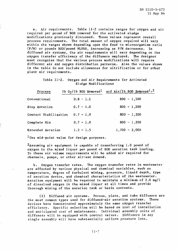
EM 1110-3-172 11 May 84
a. Air requirements. Table 11-2 contains ranges for oxygen and air required per pound of BOD removed for the activated sludge modifications previously discussed. These values represent overall process requirements. The total amount of oxygen required will vary within the ranges shown depending upon the food to microorganism ratio (F/M) or pounds BOD/pound MLVSS, increasing as F/M decreases. In diffused air systems, the air requirements will vary depending on the oxygen transfer efficiency of the diffusers employed. The designer must recognize that the various process modifications will require different air and oxygen distribution patterns. Also the values shown in the table do not include allowances for nitrification or for other plant air requirements.
Table 11-2. Oxygen and Air Requirements for Activated Sludge Modifications
Process lb Oz/lb BOD Removed! scf Air/lb BOD Removedl,2
Conventional 0.8- 1.1 800 - 1,500
Step Aeration 0.7 - 1.0 800 - 1,200
Contact Stabilization 0.7- 1.0 800 - 1,200
Complete Mix 0.7 - 1.0 800 - 1,200
Extended Aeration 1.2- 1.5 1,700- 2,000
luse mid-point value for design purposes.
2Assuming air equipment is capable of transferring 1.0 pound of oxygen to the mixed liquor per pound of BOD aeration tank loading. To these air volume requirements will be added air required for channels, pumps, or other air-use demand.
b. Oxygen transfer rates. The oxygen transfer rates in wastewater are affected by various physical and chemical variables, such as temperature, degree of turbulent mixing, pressure, liquid depth, type of aeration device, and chemical characteristics of the wastewater. Aeration equipment will be required to maintain a minimum of 2.0 mg/1 of dissolved oxygen in the mixed liquor at all times and provide thorough mixing of the aeration tank or basin contents.
(1) Diffused air systems. Porous, plate, and tube diffusers are the most common types used for diffused-air aeration systems. These devices have demonstrated approximately the same oxygen transfer efficiency. Specific selection will be based on cost of installation and anticipated cost of maintenance. Individual assembly units of diffusers will be equipped with control valves. Diffusers in any single assembly will have substantially uniform pressure loss.
11-7

EM 1110-3-172 11 May 84
Nonporous diffusers such as ejectors, impingement plates, jet-air diffusers, helix-type diffusers, and nozzles are used for aerating mixed liquor in activated sludge processes. Many of these diffusers require as much as 50 percent more air than porous diffusers.
(2) Provi~i()ns for clear1ing. systems must include provisions for cleaning the air supply to. minimize activateq sludge proce~ses.
c. Blowe~s ar1q pipi~~·
Selection and design of diffuser cle~ning the diffus~rs and for clogging disruptions of the
(1) Blowers. The supplying of air by blowers for the activated sludge process constitutes a major power requirement. Blowers will be provided in multiple units, with arrangement and capacities to meet the maximum oxygen demand with the largest unit out of service. Positive-displacement rotary and centrifugal blowers are acceptable. Centrifugal blowers will be permitted only when unit capacity requirements call for free air flows equal to or greater than 15,000 cfm. As a conservation measure, sludge-digestion gas can be more efficientiy used as fuel for driving positive-displacement blowers than for driving electric generators. ·The type, size, and number of blowers required will be determined by the anticipated maximum, peak, average, low, and minimum oxygen demands.
(2) Piping. ~ir mains will be designed so tpat pressure loss will be negligible and so that uniform air flow through each square foot of distributed surface. is attained~ !he air diffusion piping and diffuser system will be capaple of delivering 200 p~rcent of the normal air requirements. It is ~~sential that· the interior of the air pipes remain free from corrosion and scaling that might cause clogging of the diffusers. Expansion anq con~raction joints "snould be part of the piping design. Blower discharges and air delivery to aeration tanks shoulq be metered ~:t ~rifice 'or Ventu7i-type How meters.
d. Mechanical aerators. t, - f, i ."'1!
.~f), ~~ff~ce.~n,~ f~fRi~~· Surf~~~ a,ef~fOfS ~~~ p~ fixed or ff?~t~~~ 4~~~c~~ ~lfp Pt&~-~p:~9· f~~-~r,~ecJ., ~~~-se~e~, or varl:ablh:Sp.eeq motors. ' F~oahng aerators ate a~plica!He ·for use where the water elevation nuctuate~,' or where rigid support would be impractica~ •. stow:.;spe~4 sur~ace aerators' ate conHcierao~y more expensive 'than high~~peed 'uhlts despite' i:pe: fact""poth tlnits have es~·e~t~~llcY f~~ s~~~ ~~~~~#'' F~~sfef ~fft~i~t1~i~s; h6w7yer, ·low~s~e~q mechan1cal'sur£ace aerators are more rel1able and prov1de better mix~rig: ·±uiBf~e ~er~Ecl~s·~r~ nof·as eiti~~ent 1 J~ ~urfade aerators but are' usefuf'whe~e ba~tn ·~rec{ limitation~ 1 ~itt 'not 'permit the use of .,, :
lt~~~~!~~ii~~~~f~~tL''tte~~I~*t~fe r~f~Wr~~~~t~:!i~tt;tir m~~~rnicat ~~htpment .' · · ~~~h&t1P~~l ·~erat~r~''ln c6tinh~# use" ar-e··ptopttedit-y ae~Fes

EM 1110-3-172 11 May 84
with unique, usually patented characteristics. Aerator design will be based on the most adverse climatic conditions anticipated, when oxygen transfer efficiencies are lowest, to assure adequate capacity.
(2) Oxygen transfer capability. The oxygen transfer capability of aeration equipment will be determined by the following formula:
N = N0 (C8 w- Ct) x 1.024T-20 x a
Cs
where:
Caw = {3 x Cs Alpha (a) = _o_x"""y_.g._e_n_t_r_a_n_s-:f:-e_r_c_o_e_f::-f-::-:-i-"-c-:i~e....:n....:t-:i,.:;n;;._;w....:a~s....:t.:...e.:...w.;.....;;;;a....:t....:e.....:.r
oxygen transfer coefficient in tapwater Bet a ({3 ) = ...;:o..:;;x:..~:y-'gz..:e;:.:n:;:_s;:..a=t..;:u...;:r..;:a;.:t~i;.:o;.:n::.._v:..::a:..:l::-u.::e=-..:::i.::n:_:::w~a:..:s:...:t:...:e::..:w::..:a:.t:.e::.:..r
oxygen saturation value in tapwater
Use a = 0.8 and {3 = 0.9 unless laboratory data are available to demonstrate other values.
N = pounds 02/hp-hour transferred at design conditions N0 = pounds 02/hp-hour transferred at standard conditions as
rated by the manufacturer. Csw = saturation value of dissolved oxygen at design
temperature and specific elevation (appendix B). C8 = saturation value of dissolved oxygen of tapwater at
20 degrees C. and sea level; use 9.2 mg/1. C1 =DO level (mg/1) desired at design conditions; use
2 mg/1. T =Design operation temperature (degrees C.).
The designer will compute the value of N for summer and winter temperatures. The aeration equipment will be selected on the basis of the lower value of N, i.e., the lower rate of transfer.
(3) Mixing requirement. For diffused-air systems, a m1n1mum of an additional 20 scfm/1,000 cubic feet of aeration tank volume will be provided to insure good mixing. To maintain a completely mixed flow regime with mechanical aerators, allow 1.9 hp/1,000 cubic feet of aerated volume. Mixing horsepower requirements usually control aerated lagoon designs; that is, the total horsepower required for mixing is larger than the total horsepower required to meet the design oxygen demand.
e. Combination of diffused and mechanical aerators. In the last 20 years, many manufacturers have introduced equipment that mechanically disperses the air after being diffused in the aeration tank. In some of these devices, air is introduced through spargers and then dispersed
11-9

EM 1110-3-172 11 May 84
by means of a turbine mixer. Table 11-3 lists power requirements associated with various types of aerators.
Table 11-3. Power Requirements for Different Types of Aerators
Type of Aeration System
Diffused Air, Fine-Bubble
Diffused Air, Coarse-Bubble
Mechanical Aerator, Vertical Shaft (Surface Aerator)
Agitator Sparger System
11-5. Aeration tank design.
Oxygen Delivered
pounds 02/hp/hour
2.1
1.4
3.7
2.1
Power Reguired
kW-bour/pounds o2
0.35
0.55
0.20
0.35
a. Number and arrangement of aeration tanks. If the total aeration tank volume exceeds S,OOO cubic feet, except for the extended aeration process, the total capacity will be divided into two or more units capable of independent operation. Diffused-air aeration tanks, rectangular in shape, will be divided into one or more channels in such a manner that the length of travel exceeds four times the width of the channels. Inlets and outlets for each aeration tank will be suitably equipped with valves, gates, stop plates, weirs, or other devices to facilitate control of the flow and liquid levels in the tank. Channels and pipes carrying liquids with solids in suspension will be designed to maintain self-cleaning velocities (i.e., not less than 2 fps). Devices for indicating flow rates of raw sewage or primary effluent, return sludge, and air to each aeration tank will be provided.
b. Aergtion tarik 'volume. Aeration tat:tk volum.e must >satisfy the ·.foHowi'rig criteria {if inore tlian orie of-~h~S.~~·is'applicable in a given situation, the most ~tringent 'niust'•be :aatisfi~d):
. . -. .
'( t) . A''min:lm'iim detention Hme (atatation, fffue)' :ilis sti'f~d 'in -pa-r~grapn ·11~3 •
. :'
· ~ ~ frbe 1i~i tli fton. Of v~I'Urii~trtc; 1~~lt~g tp6~Jcis 1\2~~~}1 :~bbo ci~bic .. ,:_.· ;(f ) feet/day).
;·. '! d '· ij9t'f~n~f:~~~l~ahon of ~t-i~lic 1;it&~dthg':~~~~~~~~d;iln~'pdu~as -.- n6o/a~y/~oil&d "m.vss. : '· . · • ~ t4) ::1A\~~~ir~ite~: r.~~lo-~f~-.p~u~cirti~~Pl;t>~~~Jl1~~~S.$i.l~2iol~.,be. t'l.Jii~if\·ta·f*~·ct.i~lh' tiler ~·t"irf:ion':i:~nik •. _ ~l, .. t-~bj.pi':;'"-~lls #¥g~ £rfipi~o -?51 to
0.5 in c'chivEmtiorial' plants and from 0.2 to 0.5 in Step Aerati:on and

EM 1110-3-172 11 May 84
Contact Stabilization. For extended aeration, this ratio varies between 0.03 and 0.2.
(5) An optimum BOD-to-nutrient ratio of 100:5:1 of BOD : Nitrogen : Phosphorus is to be maintained for proper microbiological growth. Domestic wastewater does not need any supplemental nutrients, but it some industrial wastes encumber the system, some nutrient addition may be required.
c. Aeration tank dimensions.
(1) Conventional activated sludge. Minimum tank depth, side-water depth, (SWD), will be 7 to 10 feet for small plants (0.1 mgd) and from 10 to 14 feet for l'arger plants; minimum free board wi 11 be 2 feet. The tank bottom will slope along the longitudinal axis to a sump. Aeration tank width will be 1.65 to 2.0 times the SWD; the larger ratio is the width used for deeper tanks. For· example, a tank with a SWD of 10 feet will be 16.5 feet wide, while a tank with a SWD of 15 feet will be 30 feet wide. However, these limitations do not apply to a completely mixed system.
(2) Completely mixed activated sludge. Aeration tanks will be designed in a manner to insure proper turbulent flow of wastewater. For diffused-air systems, the air diffusers will be installed along one side of the channel and near its bottom. The opposite bottom corner will have a fillet of concrete, and deflecto! baffles (at an angle of approximately 45 degrees) placed at the water surface so as to assist in maintaining the desired circulation of liquid in the tank. The traverse velocity across the bottom of these tanks should be at least 1 fps and preferably 1.5 fps in order to prevent deposition of solids in the tank bottom. For mechanical aerator systems, the installed horsepower should not exceed 2.5 hp/1,000 cubic feet of the tank's liquid volume. The minimum liquid depth will be 10 feet and the maximum depth 12 feet. Draft-tube aerators must be used for depths greater than 12 feet, and the largest horizontal distance of the unit from wall to wall will be 24 feet. If circular tanks are used for mechanical aeration systems, internal wall baffles will be provided in order to prevent potential vortexing problems. If more than one aerator is required for an aeration basin, the minimum center-to-center spacing of the units, in feet, will be 0.8 times the unit aerator horsepower.
11-6. Final settling tank. It will be the function of the final sedimentation tank to remove solids from the aeration tank effluent. The final sedimentation tank will be designed to handle a flow equal to the projected design raw wastewater flow. The design will provide for the sludge return to the aeration tank. The design parameters indicated in paragraphs 8-3.b. and 8-4. should be observed.
11-11
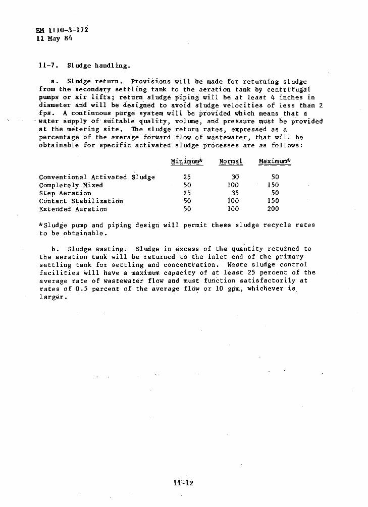
EM 1110-3-172 11 May 84
11-7. Sludge handling.
a. Sludge return. Provisions will be made for returning sludge from the secondary settling tank to the aeration tank by centrifugal pumps or air lifts; return sludge piping will be at least 4 inches in diameter and will be designed to avoid sludge velocities of less than 2 fps. A continuous purge system will be provided which means that a water supply of suitable quality, voltune, and pre·ssure must be provided at the metering site. The sludge return rates, expressed as a percentage of the average forward flow of wastewater, that will be obtainable for specific activated sludge processes are as follows:
Minimum* Normal Maximum*
Conventional Activated siudge 25 30 50 Completely Mixed 50 100 150 Step Aeration 25 35 50 Contact Stabilization 50 100 150 Extended Aeration 50 100 200
*Sludge pump and piping design will permit these sludge recycle rates to be obtainable.
b. Sludge wasting. Sludge in excess of the quantity returned to the aeration tank will be returned to the inlet end of the primary settling tank for settling and concentration. Waste sludge control facilities will have a maximum capacity of at least 25 percent of the average rate of wastewater flow and must function satisfactorily at rates of 0.5 percent of the average flow or 10 gpm, whichever is larger.

CHAPTER 12
SLUDGE HANDLING, TREATMENT, AND DISPOSAL
EM 1110-3-172 11 May 84
12-1. General considerations. Sludge, residual solids, is the end product of wastewater treatment. Primary sludge is from 3 to 6 percent solids. Treatment objectives are reduction in volume and rendering it suitable for ultimate disposal.
12-2. Sludge pumping. Sludges with less than 10 percent solids can be pumped through force mains. Sludges with solids content less than 2 percent have hydraulic characteristics similar to water; this can be assumed for design purposes. For solids content greater than 2 percent, however, friction losses are from 1-1/2 to 4 times the friction losses for water. Both head losses and friction increase with decreasing temperature. Velocities must be kept above 2 fps. Grease content can cause serious clogging, and grit will adversely affect flow characteristics as well. Adequate clean-outs and long sweep turns will be used when designing facilities of these types.
a. Piping. Sludge withdrawal piping will not be less than 6 inches in diameter. Minimum diameters for pump.discharge lines are 4 inches for plants less than 0.5 mgd and 8 inches for plants larger than 1.0 mgd. Short and straight pipe runs are preferred, and sharp bends and high points are to be avoided. Blind flanges and valves should be provided for flushing purposes.
b. Pumps. Sludge pumps will be either plunger, progressing cavity, torque-flow, or open impeller centrifugal types. Plunger and progressing cavity pumps generally should be used for pumping primary sludges; centrifugal pumps are more suitable for the lighter secondary sludges. Centrifugal and torque-flow pumps are used for transporting digested sludge in most cases; plunger and progressing-cavity pumps are used when a suction lift is involved.
12-3. Sludge digestion.
a. Aerobic sludge digestion. The major function of sludge digestion (and its principal advantage) is the stabilization of the sludge in terms of volatile content and biological activity. Aerobic digestion accomplishes this through biological oxidation of cellular matter, which is done without the excess production of volatile solids associated with anaerobic digestion. This is accomplished without the production of a high-BOD liquor as ~esults from the production of volatile acids in the anaerobic digestion process.
(1) Modes of operation. Aerobic digesters can be either continuous or intermittent batch operations. With batch operation, waste sludge feed will be discontinued at a specified time before digested sludge withdrawal. In continuous operation, supernatant is
12-1
EM 1110-3-172 11 May 84
constantly withdrawn. This mode of operation is used when phosphorus is a problem and lo~ phosphorus levels are required in the effluent, because batch operation produces high phosphorus concentrations in the supernatant.
(2) Design factors. A summary of design factors is given in table 12-1. Tank design is open (can be cold-climate problem with mechanical aeration), and no heating is required although some .. increase in volatile solids reduction can be obtained with increased temperature. Tank design is similar to aeration basin design with the addition of sludge thickening apparatus. A major disadvantage of aerobic digestion is the high energy requirement, with diffused air aeration having the highest, as it requires as much as 100 percent more horsepower than does mechanical aeration.
b. Anaerobic sludge digestion.
(1) Process description. Anaerobic digestion is the predominant method and also usually effective and energy efficient. The process involves gasification, liquefaction, stabilization, colloidal structure breakdown, and water reduction.
(2) Objectives. The objectives of anaerobic digestion are the stabilization of organic solids, sludge volume reduction, odor reduction, destruction of pathogenic organisms, useful gas production, and the improvement of sludge dewaterability. Volatile solids typically are reduced by 60 to 75 percent, with final volatile matter contents of 40 to SO percent.
(3) Conventional (standard-rate) digestion systems. This type of system will consist of a single- or two-stage process for which tanks will provide for the simultaneous digestion, supernatant separation, and concentration of sludge. The volume will be calculated for a load of from 0.04 to 0.10 pounds of volatile suspended solids per day per cubic foot or for the criteria given in table 12-2. Two-stage processes are more applicable for plants having capacities of more than 1 mgd. The minimUm total retention time will be 30 days. For two-stage processes; the retention time in the first stage will be 8 days and in the second, 22 days minimum. the sludge will be heated to
·· "''and maintained at 95 degrees F., when possibl,e., •If .. s1udge,heating is not feasible, the tank size will be increased in accordance with local climatic conditions, but not less than twice the volume computed for he a ted sludge.
12-2
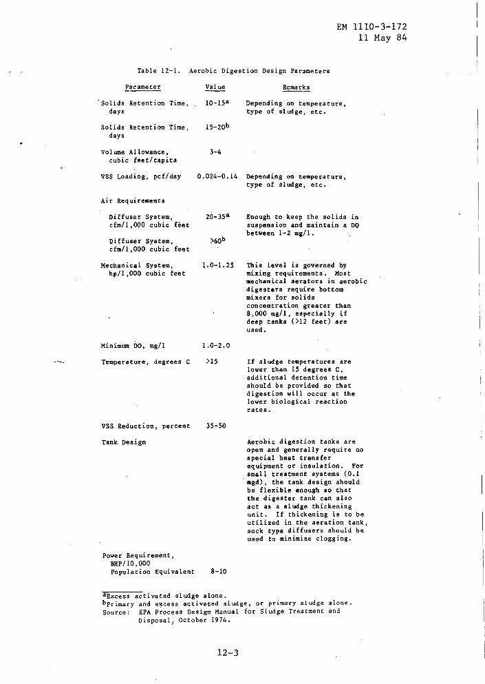
EM 1110-3-172 11 May 84
Table 12-1. Aerobic Digestion Design Parameters
Parameter
'solids Retention Time, days
Solids Retention Time, days
Volume Allowance, cubic feet/capita
VSS Loading, pcf/day
Air Requirements
Diffuser System, cfm/1,000 cubic feet
Diffuser System, cfm/1,000 cubic feet
Mechanical System, hp/1,000 cubic feet
Minimum DO, mg/1
Temperature, degrees C
VSS Reduction, percent
Tank Design
Power Requirement, BHP/10,000 Population Equivalent
Value
10-15a
15-20b
3-4
Depending on temperature, type of sludge, etc.
0.024-0.14 Depending on temperature, type of sludge, etc.
1.0-1. 25
1.0-2.0
)15
35-50
8-10
Enough to keep the solids in suspension and maintain a DO between 1-2 mg/1.
This level is governed by mixing requirements. Most mechanical aerators in aerobic digesters require bottom mixers for solids concentration greater than 8,000 mg/1, especially if deep tanks (>12 feet) are used.
If sludge temperatures are lower than 15 degrees C, additional detention time should be provided so that digestion will occur at the lower biological reaction rates.
Aerobic digestion tanks are open and generally require no special heat transfer equipment or insulation. For small treatment systems (0.1 mgd), the tank design should be flexible enough so that the digester tank can also act as a sludge thickening unit. If thickening is to be utilized in the aeration tank, sock type diffusers should be used to minimize clogging.
aExcess activated sludge alone. bprimary and excess activated sludge, or primary sludge alone. Source: EPA Process Design Manual for Sludge Treatment and
Disposal 1 October 1974.
12-3
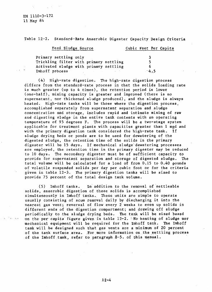
EM 1110-3-172 11 May 84
Table 12-2. Standard-Rate Anaerobic Digester Capacity Design Criteria
Feed Sludge Source
Primary settling only Trickling filter with primary settling Activated sludge with primary settling Imhoff prbcess
Cubic Feet Per Capita
3 5 6
'4 .5
(4) High-rate digestion. The high-rate digestion process differs from the standard-rate process in that the solids loading rate is much greater (up to 4 times), the retention period is lower (one-half), mixing capacity is greater and improved (there is no supernatant, nor thickened sludge produced), and the sludge is always heated. High-rate tanks will be those where the digestion process, accomplished separately from supernatant separation and sludge concentration and storage, includes rapid and intimate mixing of raw and digesting sludge in the entire tank contents with an operating temperature of 95 degrees F. The process will be a two-stage system applicable for treatment plants with capacities greater than 1 mgd and with the primary digestion tank considered the high-rate tank. If sludge drying beds or ponds are to be used for dewatering of the digested sludge, the retention time of the solids in the primary digester will be 15 days. If mechanical sludge"dewatering processes are employed, the retention time in the primary digester may be reduced to 10 days. The secondary digester must be of sufficient capacity to provide for supernatant separation and storage of digested sludge. The total volume will be calculated for a load of from 0.15 to 0.40 pounds of volatile suspended solids per day per cubic foot or for the criteria given in table 12-3. The primary digestion tanks will be sized to provide 75 percent of the total design tank volume.
(5) Imhoff tanks. In addition to the removal of settleable solids, anaerobic digestion of these solids is accomplished simultaneously in Imhoff tanks. These units are simple to operate usually consisting of scum removal daily by discharging it into the nearest gas vent; reversal of flow every 2 weeks to even up solids in different ends of the digestion compartment; and drawing off sludge periodically to the sludge drying beds. The tank will be sized based on the p'er capita figure given in table 12-2. :.No heating of sludge nor mechanical equipment will be required for the Imhoff tank. The Imhoff tank will be designed such that gas vents are a minimum of 20 percent of the tank surface area. For more information on the settling process of the .Imhoff tank, refer to paragraph 8-5. of thi.s manual.
12":4
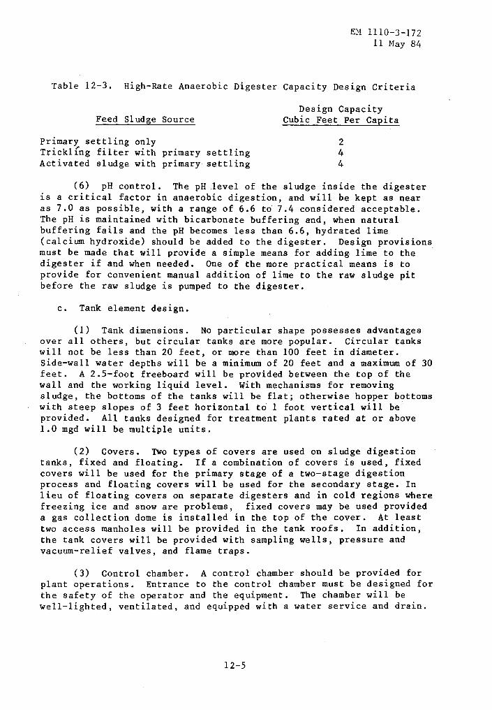
EM 1110-3-172 11 May 84
Table 12-3. High-Rate Anaerobic Digester Capacity Design Criteria
Feed Sludge Source
Primary settling only Trickl[ng filter with primary settling Activated sludge with primary settling
Design Capacity Cubic Feet Per Capita
2 4 4
(6) pH control. The pH _level of the sludge inside the digester 1s a critical factor in anaerobic digestion, and will be kept as near as 7.0 as possible, with a range of 6.6 to 7.4 considered acceptable. The pH is maintained with bicarbonate buffering and, when natural buffering fails and the pH becomes less than 6.6, hydrated lime (calcium hydroxide) should be added to the digester. Design provisions must be made that will provide a simple means for adding lime to the digester if and when needed. One of the more practical means is to provide for convenient manual addition of lime to the raw sludge pit before the raw sludge is pumped to the digester.
c. Tank element design.
(1) Tank dimensions. No particular shape possesses advantages over all others, but circular tanks are more popular. Circular tanks will not be less than 20 feet, or more than 100 feet in diameter. Side-wall water depths will be a minimum of 20 feet and a maximum of 30 feet. A 2.5-foot freeboard will be provided between the top of the wall and the working liquid level. With mechanisms for removing sludge, the bottoms of the tanks will be flat; otherwise hopper bottoms with steep slopes of 3 feet horizontal t~ 1 foot vertical will be provided. All tanks designed for treatment plants rated at or above 1.0 mgd will be multiple units.
(2) Covers. Two types of covers are used on sludge digestion tanks, fixed and floating. If a combination of covers is used, fixed covers will be used for the primary stage of a two-stage digestion process and floating covers will be used for the secondary stage. In lieu of floating covers on separate digesters and in cold regions where freezing ice and snow are problems, fixed covers may be used provided a gas collection dome is installed in the top of the cover. At least two access manholes will be provided in the tank roofs. In addition, the tank covers will be provided with sampling wells, pressure and vacuum-relief valves, and flame traps.
(3) Control chamber. A control chamber should be provided for plant operations. Entrance to the control chamber must be designed for the safety of the operator and the equipment. The chamber will be well-lighted, ventilated, and equipped with a water service and drain.
12-5

EM 1110-3-172 11 May 84
(4) Piping. The particular p1p1ng requirements for sludge digesters will include provisions for adding sludge, withdrawing sludge, multi-level supernatant removal points, heating, recirculating sludge or supernatant, flushing, sampling gas collecting, and gas recirculating. All supernatant will be returned to process for further treatment. Supernatant draw-off facilities will be designed to provide variable-rate return to prevent plant upset.
(5) Heating. The method to be used for heating sludge digestion tanks is the circulation of the contents of the tank through a heat exchanger. Heated tanks will be insulated and the heating equipment sized to maintain a temperature of 95 degrees F. during the coldest weather conditions.
(6) Chemical feeding. Practical means for feeding lime or other chemicals that are commonly used to correct digester operational problems must be included as part of the digester design.
(7) Gas collection. Sludge gas will be collected from the digesters either for utilization or for burning it to waste. Two-stage units will provide interconnecting lines permitting transfer and storage from one unit to the other.
(8) Gas utilization. Gas storage facilities will have to be provided if the gas is to be utilized and not wasted by burning. Sludge gas has a heat value of between 500 and 700 Btu/cubic feet. An average gas yield is 15 cubic feet per pound of volatile solids destroyed.
12-4. Sludge storage.
a. Sludge tanks. Sludge storage tanks may have depths no less than 15 feet and bottom slopes of 1 to 4. The tanks may be open or closed. Ventilation must be provided with closed tanks. Decanting lines as well as sludge withdrawal lines must be provided for all tanks.
b. Sludge retention ponds. Sludge retention facilities will be provided at either the treatment plant or land application site. The design detention period will be large enough to compensate for periods when sludge spreading is not feas·ible but will not be less than 30 days. Storage will permit operational flexibility, additional destruction of pathogens, and further sludge stabilization.
c. Sludge storage ponds. Sludge storage ponds are applicable for storage of well-digested sludge when land area is available. Storage is usually long-term (2 to 3 years), with moisture content being reduced to 50 to 60 percent. Lagoon storage can be used as a continuous operation or can be confined to peak load situations, and serves as a simple and economical sludge storage technique. Land
12-6

EM 1110-3-172 11 May 84
requirements and possible ground water pollution are the major disadvantages.
12-5. Sludge drying. Sludge drying beds rely on drainage and evaporation to effect moisture reduction. These beds are open, and as such ~re very susceptible to climatic conditions such as precipitation, sunshine, air temperature, relative humidity, and wind velocity. For example, a sludge drying in 6 weeks in the summer would take at least 12 weeks to dry in the winter. Sludge bed drying efficiency can be improved significantly by covering the bed with glass or plastic. Area requirements can be interpreted in terms of the per capita values in table 12-4. These values are very arbitrary and depend largely on climatic conditions. Embankment height·will be 12 to 36 inches using concrete, concrete-block, earth dr timber walls. Underdrains are to be provided with lateral tiles 12 feet apart and their transported leachate must be returned to the head of the treatment plant. Sand depth will be 9 to 18 inches, with the sand being washed and dirt-free. The sand will have an effective size of between 0.3 to 0.75 mm, with a uniformity coefficient of not more than 4.0. Anthracite coal, pea gravel, and washed grit have also been used as bedding. Sludge distribution can be of various design, although an impervious splash plate of some kind is always provided. Sludge cake removal can be by hand or mechanical means. Bed widths may range from 15 to 25 feet, with lengths of 50 to 150 feet. Multiple beds provide operational flexibility and will be used if appropriate. Sides of enclosed beds will be no higher than 36 inches but will be oriented with the sun such that shading of the sludge is held to a minimum. Open sides, forced ventilation, and artificial heating are enclosed bed modifications. Usually, a combination of open and closed beds performs best in average situations. Odor and insects can be a problem unless the sludge is digested completely. Land requirements and sludge cake removal costs are other disadvantages.
Table 12-4. Area Required for Sludge Drying Beds (Square feet per capita)
Type of Sludge Open Beds Covered Beds
Primary digested 1.5 1.0 Primary and humus digested 1.75 1.25 Primary and activated digested 2.5 1.5
Note: For facilities to be located in regions south of latitude 35 degrees, open bed area requirements may be reduced by 0.5 square feet per capita for all types of sludge and 0.25 square feet per capita for covered beds.
12-6. Sludge disposal. The proper treatment of all residual sludge streams will be provided for in each plant design. The methods of final disposal can be broadly categorized as disposal or utilization
12-7
EM 1110-3-172 11 May 84
procedures. The sanitary landfill and land surface application are, respectively, disposal and utilization methods most suitable for Army installations. The method selected for final sludge disposal or utilization must be in accordance with regulatory agency requirements.
a. Land spreading of sludges. Cropland application and land application are the major sludge utilization methods. The application of sludge to land is economical and simple, but its use may be limited because of the presence of heavy metals in the sludge, public resistance, and the availability of suitable land. In developing a system for the application of either liquid or dewatered sludge to cropland, the mode of transportation, application procedure, and rate of application must be considered.
(1) Transportation. Tank trucks, rail, and pipelines are suitable means for transporting sludge. Sludge characteristics, elevation differences, distance, sludge volume, and land availability are important factors in selecting a method for transporting sludge from the treatment plant to the utilization site. Tank trucks afford flexibility in the selection of utilization sites but their ton-to-mile cost is relatively high. Their use is most feasible where there is available land near the treatment plant. Pipelines are feasible when there is assurance of the availability of land for a long period.
(2) Application procedures. The application of sludge can be accomplished by the following procedures:
(a) Spraying on site. (b) Gravity flow from tank truck. (c) Furrowing. (d) Deep disking.
Furrow irrigation is less objectionable than spray irrigation, which is more visible and which may generate a mist of suspended droplets of liquid that can be blown away from the application areas. The sludge placed deep into the natural soil by burial, deep disking, or rotary tilling, is desirable but not necessary.
. (3) Application rates. Sludge composition, soil characteristics, climate, vegetation, and cropping practices will determine the application rate to be used for cropland utilization. It can be assumed that the allowable design application rate of either liquid or dewatered sludge will rarely exceed 20 tons of dry solids per acre per year. Much higher application rates (100 tons of dry solids per acre per year) may be used to reclaim low-quality land, but proper precautions must be taken to prevent or control potential leachate or surface runoff problems. Local representatives of the U.S. Department of Agriculture should be consulted to learn about local soil conditions and their suitability for specific sludge application rates.
12-8
EM 1110-3-172 11 May 84
b. Landfill disposal of dewatered and stabilized sludge. Most landfills will eventually produce leachate, as well as gases. The quality of leachate depends on the degree of decomposition activity within the landfill. Adequate digestion or chemical stabilization of sludge before disposal to a landfill is essential to avoid poor quality of leac!tate. To minimize leachate contamination, the landfill operation will be above the high ground water table, and surface runoff from areas tributary to the landfill will be intercepted in drainage ditches to carry it around the landfill. It may be necessary to collect and treat leachate before it reaches a stream or other fresh surface or ground water supply. Prevention of rainfall percolation into the landfill also reduces the pollution potential. This will be accomplished by adequate surface slopes in combination with impervious surface ditches, maintenance of the landfill surface, such as filling settlement areas immediately, and use the planting of cover crop to consume a large volume of water. The use of tight cover material also will decrease the rate of rainfall percolation, but adequate vents must be provided for the gases that are produced in the decomposition process.
12-9
CHAPTER 13
DISINFECTION
EM 1110-3-172 11 May 84
13-1. General considerations. Disinfection is a process 1n which pathogenic organisms are destroyed or inactivated. Several methods have been utilized and include the following: (1) physical agents, (2) mechanical means, (3) radiation, and (4) chemical agents. Physical agents include heat (boiling) and light. Mechanical means include the removal of pathogens during wastewater treatment. Radiation utilizes gamma rays to sterilize wastewater. Chemical disinfection is the most commonly used method and will be used for mobilization work unless other methods outlined above become expedient or feasible.
13-2. Types of chemical disinfectants. Chemical disinfectants include {1) chlorine and its compounds, (2) bromine, (3) iodine, (4) ozone, (S) alcohols, and (6) various alkalies and acids. Discussion herein is limited to disinfection of wastewater treatment plant effluents by chlorine and its compounds since it is the most universally accepted disinfectant. Other chemicals as outlined above may be employed when chlorine is not available.
13-3. Design basis and criteria.
a. Chlorine forms. Chlorine is available as a liquid contained in cylinders or in the form of chlorine compounds such as calcium hypochlorite or sodium hypochlorite. These are the most commonly used compounds for disinfection. Liquid chlorine is evaporated and dissolved into the wastewater as a gas. Sodium hypochlorite is, available in solution form, calcium hypochlorite is available in solid form.
b. Limitations on chlorine. Although chlorine is an effective disinfectant when in actual contact, the chlorine may not always come in contact with the microorganisms. Bacteria and viruses can hide (and often do) inside particles of suspended or colloidal matter. Therefore, chlorine disinfection will not guarantee removal of all health hazards from wastewater. Chlorine disinfection involves a very complex series of events and is influenced by the kind and extent of reactions with chlorine-reactive materials, temperature, pH, suspended solids concentrations, and the resiliency of some pathogenic organisms. Effective treatment will reduce the need for disinfection so proper design and operation of the treatment plant are essential. Nitrogen compounds in the wastewater affect chlorine dosages. Sufficient chlorine must be added to overcome their neutralizing effect.
c. Design parameters. For chlorination of wastewater treatment plant effluent, a detention period of 30 minutes in the contact chamber to provide maximum disinfection is required. Table 13-1 should be used to estimate chlorine dosage requirements.
13-1

EM 1110-3-172 11 May 84
Table 13-1. Typical Chlorine Dosages Required for Sewage Disinfection
Type of Effluent to be Disinfected
Raw Wastewater Raw Wastewater (Septic) Settled Wastewater Settled Wastewater (Septic) Trickling Filter Effluent Activated Sludge Effluent
Dosage mg/1
20 so 20 40 15
8
Dosage pounds/mil gallon
167 417 167 334 126
67
For the recommended treatment scheme presented in chapter 5, chlorine dosages of 15 mg/1 or 126 pounds/mil gallon will be applied at average daily flows and a maximum of 27 mg/1 or 226 pounds/mil gallon will be applied at peak daily flow rates, when disinfection is required. Sodium hypochlorite solution normally provides 12.5 percent available chlorine, and calcium hypochlorite solution normally provides 70 percent available chlorine. To determine the equivalent dosages required for these chemicals if used to disinfect the various types of effluents described above, divide the dosage figures by the fraction of available chlorine attributable to the specific chlorine compound. Chlorination of wastewater can reduce its BOD by 15 to 35 percent; this is a common practice to relieve overloaded plants until additional capacity is provided. Approximately 2 mg/1 of BOD can be removed by 1 mg/1 of chlorine up to the point at which residual chlorine is produced. Odor control can be achieved by prechlorination doses of 4 to 6 mg/1. Odors off sludge drying beds can be reduced by applying calcium hypochlorite at a rate of 1/2 pound per 100 square feet of bed area. Periodic application of chlorine to trickling filter influent will reduce filter clogging and pending. A chlorine dose of 1 to 10 mg/1 based on the returned sludge flow is sometimes required for control of bulking sludge in an activated sludge process. A chlorine residual of 1 mg/1 in sludge thickener supernatant prevents sludge from becoming septic during its holding period.
d. Mixing. Rapid mixing at the point of chlorine application is critical for disinfection efficiency, while adequate mixing at the same point is critical for control purposes. The following methods are acceptable mixing practices to be used at Army installations: the hydraulic jump, submerged weir, the over and under baffle, the mechanical mixer, and the closed conduit flowing full and with adequate turbulence.
13-4. Chlorine feeding equipment. The chlorinator capacity will be designed to have a capacity adequate to provide the dosage requirement stipulated in paragraph 13-3.d. at maximum flow conditions. Design considerations will be based on the assumption that chlorine can be
13-2
EM 1110-3-172 11 May 84
vaporized from 150-pound cylinders at a rate of 40 pounds per 24 hours, 30 pounds per 24 hours from lOS-pound cylinders, and 450 pounds per 24 hours from 1-ton cylinders. Where greater rates of feed are required,. a suitable number of containers will be manifolded, unless facilities are installed to prevent chlorine system freezing due to evaporation. The use of 1-ton cylinders will be used where the average daily chlorine consumption is over 150 pounds.
a. Direct feed chlorinator. The use of equipment for feeding chlorine gas from the cylinder through a control apparatus to the point of application is not permitted except under special conditions which prevent the use of solution-feed chlorinators.
b. Solution feed chlorinator. Pressure-feed type and vacuum-feed type are, in general, two types of solution feeders. The. vacuum-feed type chlorinator is the preferred type and will be used for all installations where a suitable make-up water supply is available, such as potable water or suitable plant effluent.
c. Hypochlorite feeders. positive-displacement metering installations designed for the
These feeders are of the mechanical type and their use will be limited to addition of hypochlorite solution.
d. Scales. Scales will be sized to accommodate the maximum number of cylinders required to serve the maximum chlorine rate. They may be mounted flush with the floor or on the floor surface within an enclosing box. With above-floor mounting, overhead hoist equipment must be considered. Flush-mounted scales will require drainage of the scale sump. A loss-of-weight recorder is desirable to provide a continuous record of chlorine feed.
e. Hoists. Electric hoisting equipment is recommended for installations using 1-ton cylinders. Hoists will have a m1n1mum capacity of 2 tons and will be equipped with an approved type of lifting-beam container grab.
f. Piping. Only pipe and materials suitable for chlorine and chlorine solutions such as PVC plastic pipe, rubber-lined pipe, or materials otherwise acceptable by the manufacturers of chlorine equipment will be used in chlorine installations. Piping and valves will be identified as components of the chlorination system.
g. Housing.
(1) Room separation. If chlorinators and/or cylinders are in a building used for other purposes, a gas-tight partition will separate the chlorine room from any other portion of the building. Doors to the room will open only to the outside of the building and will be equipped with panic ha.rdware. The storage area will be separated from the feed area.
13-3

EM 1110-3-172 11 May 84
(2) Inspection window. A clear glass, gas-tight window will be installed in an exterior door or interior wall of the chlorinator room to permit the chldrinator to be viewed without entering the room.
(3) Heat. Chlorine equipment rooms will be provided with a means of heating so that a room temperature of at least 60 degrees F. can be maintained. This will help insure a continuous flow of gas from the chlorine cylinder and will help prevent the formation of chlorine hydrate in the chlorinator.
(4) Ventilation. Forced, mechanical ventilation, which will provide one complete air change every 3 minutes, will be installed. The entrance to the air exhaust duct from the room will be near the floor, and the point of discharge will be so located as not to contaminate the air inlet to any building or inhabited areas. Air inlets will be so located as to provide cross-ventilation. To prevent a fan from developing a vacuum in the room, thereby making it difficult to open the doors, louvers should be provided above the entrance door and opposite the fan suction. Where duct work is required to carry air to the fan, it should be laid out so that the suction openings are at floor level and spaced so as to exhaust air from all equipment areas. Exhaust openings should be designed so that covers are not required.
(5) Electrical controls. A common control for the fans and lights keyed to an exterior lock on the entrance door will be installed so that they will automatically come on when the door is opening, will only be deactivated by relocking the door externally, and can also be manually operated from the outside without opening the door.
(6) Cylinder storage. A storage area will be provided to allow for a minimum 15-day inventory of reserve and empty containers. Cylinders may be stored outdoors on suitable platforms at or above grade and under cover of a well-ventilated fireproof structure.
(7) Precautions in the use of chlorine. The presence of chlorine gas in the atmosphere can pose immediate and serious hazards to the health of any person breathing the air. Gas masks approved by the National Institute for Occupational Safety and Health (NIOSH) will be provided outside any area where an individual would be exposed in the event of chlorine leaks, spills, etc. All rooms in which chlorine is to be stored or handled should be adequately ventilated to the outside. A fan automatically turned on prior to entry into the chlorination or storage facility will be provided. Since chlorine gas is heavier than air, vent outlets will be placed at floor level. Chlorine detectors of the electronic, solid state type, sensitive to one part per million chlorine (by volume) in air, that continuously monitor the air for chlorine will be installed to provide a visual/audible alarm in the event of a chlorine leak. Alternatively, the enclosed space should be entered only if the worker is under observation by a co-worker and if the worker has in his possession a
13-4
EM 1110-3-172 11 May 84
respirator suitable for escape. The applicable safety recommendations as given in AWWA Manual No. 3 and WPCF Manual of Practice No. 1 should be followed. Information on the properties of chlorine and its safe handling are also available in the CI Chlorine Manual. When hypochlorite compounds are used, the above requirements do not apply.
13-5. Chlorine contact chambers. A chlorine mixing contact chamber will be designed to provide a minimum of 30 minutes detention time at the average design flow. Consideration will be given to two flow-through units with common wall construction so that their total volume satisfies detention requirements, to allow for periodic cleaning. Minimize short-circuiting with inlet baffles and end-around baffling within the tank. The chlorine feed rate will be proportioned in accordance with the flow and the chlorine demand of the wastewater. Adequate mixing during the chlorine contact period will be insured by the installation of adequate baffling, or by mechanical mixing equipment.
13-6. Residual limitations. Residual chlorine in the plant effluent must be kept to just below 1.0 mg/1.
13-5

CHAPTER 14
SMALL SEWAGE TREATMENT FACILITIES
EM 1110-3-172 ll May 84
14-1. General considerations. Treatment plants handling less than 1.0 mgd are generally considered small treatment plants. The principles of design are no different, but the choice of equipment will usually differ from that used in large plants. This is usually due to the effect of economies of scale, whereby certain operations are economically feasible only on a large scale. This is often the case for certain sludge handling systems and most advanced treatment operations. Small plants must make larger safety factor allowances for flow variation and temperature effects relative to total wastewater flows. Smaller plants inherently have less operational flexibility; however, they are capable of performing effectively and efficiently. These small treatment plants may consist of wastewater stabilization ponds, trickling filter plants, physical-chemical plants, extended aeration activated sludge plants, and septic tanks. Design criteria for septic tanks are given below. Criteria for other processes have been presented in previous chapters.
14-2. Septic tank design factors. Septic tanks, with appropriate effluent disposal systems, are acceptable as a treatment system for isolated buildings or for single-unit residential buildings when permitted by a regulatory authority and when alternative treatment is not practical. When soil and drainage characteristics are well documented for a particular site, septic tank treatment may be permanently feasible. Septic tanks perform settling and digestion functions, are effective in treating from 1 to 300 population equivalents of waste, but will be used only for 1 to 25 population equivalents, except when septic tanks are the most economical solution for larger populations within the above range. Minimum size will be at least 500-gallon capacity. In designing tanks, the length-to-width ratio should be between 2:1 and 3:1, and the liquid depth should be between 4 and 6 feet. Detention time depends largely on the method of effluent disposal. When effluent is disposed of in subsurface drainage fields, 24 hours detention time based on average flows is required. The septic tank must be sized to provide the required detention (below the operating liquid level) for the design daily flow plus an additional 25 percent capacity for sludge storage. If secondary treatment such as a subsurface sand filter or an oxidation pond is provided, this can be reduced to 18 hours. Open sand filter treatment can further reduce detention time to 10 or 12 hours. Tile field and leaching well disposal will be limited to small facilities (less than 50 population equivalents). For larger operations, discharge of effluent is usually through dosing tanks which periodically discharge effluent quantities near 80 percent of the drainage system capacity.
14-3. Subsurface irrigation design factors. Subsurface irrigation can be used in conjunction with septic tank treatment when soil conditions
14-1

EM 1110-3-172 11 May 84
permit. Percolation tests must be performed as required by the U.S. Public Health Service, and the ground water table at the highest known or anticipated level must not reach the invert of the lowest tile line.
14-4. Package treatment plants. Complete package treatment plants can be obtained from various manufacturers; these plants may present a practical and flexible solution to many wastewater handling problems. However, the modified activated sludge plants may require relatively high amounts of electrical energy consumption to operate aeration equipment. The systems are usually based on biological treatment, with modified aeration techniques such as extended aeration. These systems are capable of handling population equivalents of 10 to more than 1,000, but will be considered for flows of 0.1 mgd or less. Some prefabricated plants may be relocated, depending on size and original construction. Specific design details are obtainable from individual manufacturers.
14-2
CHAPTER 15
SAFETY FEATURES
EM 1110-3-172 11 May 84
15-1. General considerations. The designer must be aware of the oc~upational and public health hazards associated with plant operations and maintenance and provide the safety features to control such hazards. These hazards include mechanical equipment, open pits and tanks; electrical components; toxic, infectious and flammable materials; and potential oxygen-deficient situations.
15-2. Applicable standards. The following will be considered minimum standards. Additional standards may apply depending on the particular plant design and individual features.
a. AR 385-10 Army Safety Program.
b. AR 40-5 Health and Environment.
c. OSHA Standards. Design features will be consistent with the requirements of standards promulgated by OSHA.
15-3. Safety features in plant design. The following safety features listed below are minimum general requirements and are not intended to be all-inclusive. For detailed requirements refer to the applicable standards.
a. Assure adequate ventilation in wet wells and dry wells. The chlorine storage area will be separated from the feed area and from the remaining plant areas. Mechanical exhaust ducts for chlorine storage rooms and the chlorination room will extend from near the floor level and exhaust outside the building. The design will allow for provision of adequate make-up air. Positive mechanical ventilation will be ample in grit and screening chambers as well as in the wet and dry wells. Fan capacities must be sufficient to effect a complete change of air every 2 to 5 minutes. Emergency generators with internal combustion engines will have their exhausts vented outside of the building to prevent carbon monoxide build-up during test or emergency use.
b. Fencing and guard rails will be provided for open tanks, hatchways, and other locations when needed. Stairs will be used for access to pump rooms in preference to vertical ladders. However, when vertical ladders cannot be avoided and their length exceeds 20 feet, they will be equipped with a ladder climbing device, a hoop cage, or offset landings.
c. All electrical w1r1ng will be properly insulated and grounded. Explosion-proof equipment will be provided for enclosed or confined areas where explosive vapors, fumes or gases may accumulate; 110 volts or less for control circuits 1s desirable in such areas.
15-1

EM 1110-3-172 11 May 84
d. Guards will be provided for all exposed moving parts of pumps and equipment. Hoists and rails for removal of heavy equipment will also be provided for operation and maintenance purposes.
e. The plant will be fenced as necessary to protect the public and the facility.
f. The public water supply must be protected to eliminate the possibility of contamination by cross-connections with sewage or sludge piping. This will be achieved by a vertical positive air gap no less than 2 inches between the inlet and the outlet levels of a fixture. The water line utilized for plant washdown will be provided with a backflow prevention device.
g. Signs will be provided designating hazardous areas and nonpotable water taps.
h. Flood lights will be provided for night-time inspection and maintenance.
1. Crowding of equipment will be avoided around pumps, screens, and vacuum filters. Valves and other operating devices must be readily accessible to avoid injury and encourage proper use so that spillage will be prevented.
j. Sludge digestion tanks will be segregated from the rest of the plant and provided with liquid-level indicators or alarms.
k. Good ventilation and a combustible gas indicator will be provided for protection against any leakage in the gas-collection piping and appurtenances.
1. Piping and valves in chlorine room will be color-coded with a primary color of brown and a secondary color of green.
15-4. Safety equipment. Facilities for the following safety equipment must be provided for at the plant:
a. Safety harness ~ith lifeline.
b.
c. Fire extinguish~rs (type suitable for anticipated fires).
d. A portable co~bustible gas indicator where sludge gas is collected.
e. An oxygen deficiency indicator.
f. Hydrd~eh sulfide and carbon monoxide indicators.
15-2

g. A portable air blower.
EM 1110-3-172 11 May 84
h. Two or more pressure demand-type compressed-air masks, certified by NIOSH.
15-5. Quick shower. A suitable facility for quick drenching or flushing of the eyes and body will be provided within areas where chemicals are handled, stored, or used except when water presence is a hazard with the chemical.
15-3

APPENDIX A
SAMPLE PROBLEMS
A-1. Sedimentation.
EM 1110-3-172 11 May 84
a. Design requirements and criteria. Design a sedimentation unit to" provide settling for a sewage flow rate of 4 mgd with suspended solids concentration of 300 mg/1. The following conditions apply:
Surface loading rate = 600 gpd/square foot Suspended solids removal = 60 percent Sludge solids content = 4 percent Sludge specific density_= 1.02 .
b. Calculations and results.
(1) Calculate total tank surface area,
Surface = Flow Rate = 4,000,000 gpd Area Surface Loading Rate 600 gpd/square foot
= 6,666.7 square feet
use 6,670 square feet
(2) Using a depth of 8 feet, calculate total volume.
V = 8 x 6,670 = 53,360 cubic feet
(3) This volume can be divided among three rectangular tanks (in parallel) 20 feet wide and 120 feet long with a length-to-width ratio of 6 to 1. Two circular tanks (in parallel) 65 feet in diameter would also be suitable. This will provide flexibility of operation during routine or emergency maintenance and operations cleaning and repair of the units.
(4) Calculate weir length requirement assuming three rectangular tanks and allowable weir loading rate of 12,000 gpd/linear foot.
Design Flow per Tank = Total Flow 3
= 4,000,000 gpd = 1,333,333 gpd 3
Weir Length/Tank= 1,333,333 gpd = 111 linear feet 12,000 gpd/linear foot
(5) Compute weight of solids removed assuming 60 percent removal:
A-1
EM 1110-3-172 11 May 84
Weight Removed = 4 mgd x 300 mg/1 x 8.34 pounds/gallon x 0.60
= 6,000 pounds/day
Therefore 1,500 pounds are removed per 1 mgd flow.
(6) Calculate sludge volume assuming a specific gravity of 1.02, and a moisture content of 96 percent (4 percent solids),
Sludge Volume = ~~77~6~,o~o~o~.p~o~u~n~d7s~/~d=a~y---.~~~ 1.02(62.4 pounds/cubic foot)(0.04)
= 2.,360 cubic feet/day (at 4 mgd)
= 17,700 gpd
(7) Sludge handling in this example consists of removing sludge from the settling tank sludge hopper using a telescoping sludge valve which discharges the sludge into a sump from which it is removed by a sludge pump (or pumps). Assume that the sludge will be wasted every 8 hours and pumps for one-half hour to the digester.
Sludge Sump Capacity = Daily Sludge Volume Number of Wasting Periods Per Day
= 2,360 cubic feet 3
= 787 cubic feet (= 5,900 gallons)
Increase capacity 10 percent to compensate for scum removal volumes:
Sludge Pumping Capacity = Sludge and Scum Volume/Wasting Period 30 minutes pumping/Wasting Period
= 6,500 gallons = 217 gpm; use 220 gpm 30 minutes
c. Pumps. Pump types used to convey sludge include the plunger, progressing-cavity, centrifugal, and torque-flow. The pump information provided ·is for guidance only and does not represent design criteria. For more information, refer to Pump Application Engineering.
(1) Plunger. The advantages of plunger pumps may be listed as follows:
(a) Pulsating action tends to concentrate the sludge in the hoppers ahead of the pumps.
A-2

EM 1110-3-172 11 May 84
(b) They are suitable for suction lifts up to 10 feet, and are self-priming.
(c) Low pumping rates can be used with large port openings.
(d) Positive delivery is provided unless some object prevents the ball check valves from seating.
(e) They have constant but adjustable capacity, regardless of large variations in pumping head.
(f) Large discharge heads may be provided for.
(g) Heavy-solids concentrations may be pumped if the equipment is designed for the load conditions.
Plunger pumps come in simplex, duplex, and triplex models with capacities of 40 to 60 gpm per plunger, and larger models are available. Pump speeds will be between 40 and 50 rpm, and the pumps will be designed for a minimum head of 80 feet, since grease accumulations in sludge lines cause a progressive increase in head with use. Capacity is decreased by shortening the stroke of the plunger; however, the pumps seem to operate more satisfactorily at, or near, full stroke. For this reason, many pumps will be provided 'with variable-pitch V-belt drives for speed control of capacity.
(2) Progressing-cavity. The progressing-cavity pumps can be used successfully, particularly on concentrated sludge. The pump is composed of a single-threaded rotor that operates with a minimum of clearance in a double-threaded helix of rubber. It is self-priming at suction lifts up to 28 feet, is available in capacities up to 350 gpm, and will pass solids up to 1.125 inches in diameter.
(3) Centrifugal. With centrifugal pumps, the objective is to obtain a large enough pump to pass the solids without clogging and a small enough capacity to avoid pumping a sludge diluted by large quantities of the overlying sewage. Centrifugal pumps of special design can be used for pumping primary sludge in large plants (greater than 2 mgd). Since the capacity of a centrifugal pump varies with the head, which is usually specified great enough so that the pumps may assist in dewatering the tanks, the pumps have considerable excess capacity under normal conditions. Throttling the discharge to reduce the capacity is impractical because of frequent stoppages; hence it is essential that these pumps be equipped with variable-speed drives. Centrifugal pumps of the bladeless impeller type have been used to some extent and in some cases have been deemed preferable to either the plunger or screw-feed types of pumps. Bladeless pumps have approximately one-half the capacity of conventional nonclog pumps of the same nominal size and consequently approach the hydraulic
A-3
EM 1110-3-172 11 May 84
requirements more closely. The design of the pump makes clogging at the suction of the impeller almost impossible.
(4) Torque-flow. This type of pump, which uses a fully recessed impeller, is very effective in conveying sludge. The size of particles that can be handled is limited only by 'the diameter of the suction or discharge valves. The rotating impel'ler develops a vortex in the sludge so that the main p'ropulsive Jo't'ce is the liquid itself.
' ' '
( 5) Pump application. Types of sludge that will be pumped include primary, 't'rick1ing .... fil ter and act'ivated, thickened, and conce'ntr.ated. Scum 'that accumulates· at various points in a treatment plant must also be pumped.
(6) Primary sludge. Ordinarily, it is desirable to.obtain as concentrated a sludge as practicable from primary tanks. The character of primary sludge will vary considerably, depending on the characteristics of the solids in the wastewater, the types of units and their efficiency, and where biological treatment follows, the quantity of solids added from:
- Overflow liquors from digestion tanks,
- Waste activated sludge,
- Humus sludge from settling tanks following trickling filters.
Primary sludge should be given special consideration since it is denser, and contains more grit and trash than secondary sludge •. Pumps having any chance of clogging will not be used. Plunger pumps may be used on primary sludge. Centrifugal pumps of the screw-feed and bladeless type, and torque-flow pumps may also be used.
(7) Trickling-filter and activated sludge. Sludge from trickling filters is usually of such homogeneous char:act¢r that it can be easily pumped with either plunger or nonclog centrifugal p~mps. Return activated sludge is dilute and contains only fine solids, so that it may be pumped readily with nonclog centrifugal pumps, which must operate at slow speed to help prevent the flocculent character of the sludge from being broken up.
(8) Scum pumping. Screw-feed pumps, plunger pumps, and pneumatic ejectors may be used for pumping scum.· Bladeless or torque-flow centrifugal pumps may also be used for this service.
A-2. Single stage stone-media trickling filters.
a. Design requirements and criteria. Design a trickling filter to treat 2 mgd of primary settled effluent, under the following conditions:
A-4

Raw wastewater BOD = 250 mg/1
Primary clarifier BOD removal efficiency = 30 percent
Required effluent BOD = 30 mg/1
Design temperature 20 degrees C.
Design without and with recirculation
b. Calculations and results.
EM 1110-3-172 11 May 84
(1) Design without recirculation. Therefore, R = 0, F = 1
Primary treated effluent BOD= 250(1-0.3) = 175 mg/1
Required Trickling Filter Efficiency = 175-30 175
= 0.83
Since the design temperature is 20 degrees C. no temperature correction is required.
BOD loading to the filter =
(2.0 mgd) x (175 mg/1) x 8.34 pounds/mil gallon mg/1
= 2,920 pounds/day
Assume a practical filter depth of 6 feet for stone-media filters. Apply NRC formula
E = 100 1 + 0.0085-fii/VF
Resulting 1n
83 = 100 1 + 0.0085~2,920/V
Solving for the volume
V = 5.03 acre feet
= 219,000 cubic feet
A-5
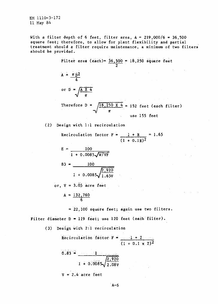
EM 1110-3-172 11 May 84
With a filter depth of 6 feet, filter area, A= 219,000/6 = 36,500 square feet; therefore, to allow for plant flexibility and partial treatment should a filter require maintenance, a minimum of two filters should be provided.
Filter area (each)= 36,500 = 18,250 square feet 2
orD=j'o/
Therefore D = -vf18,2!0 X 4 = 152 feet (each filter)
use 155 feet
(2) Design with 1:1 recirculation
Recirculation factor F = 1 + R = 1.65
E = 100 1 + 0.0085~
83 = 100
1 + 0.0085
or, V = 3.05 acre feet
A= 132,760 6
(1 + 0.1R)2
= 22,100 square feet; again use two filters.
Filter diameter D = 119 feet; use 120 feet (each filter).
(3) Design with 2:1 recirculation
Recirculation factor F = 1 + 2 _...;;_..;;.,__...;;__...,-;:'
(1 + 0.1 X 2P
1 + o .'oba
v = 2.4 acre feet
A-6
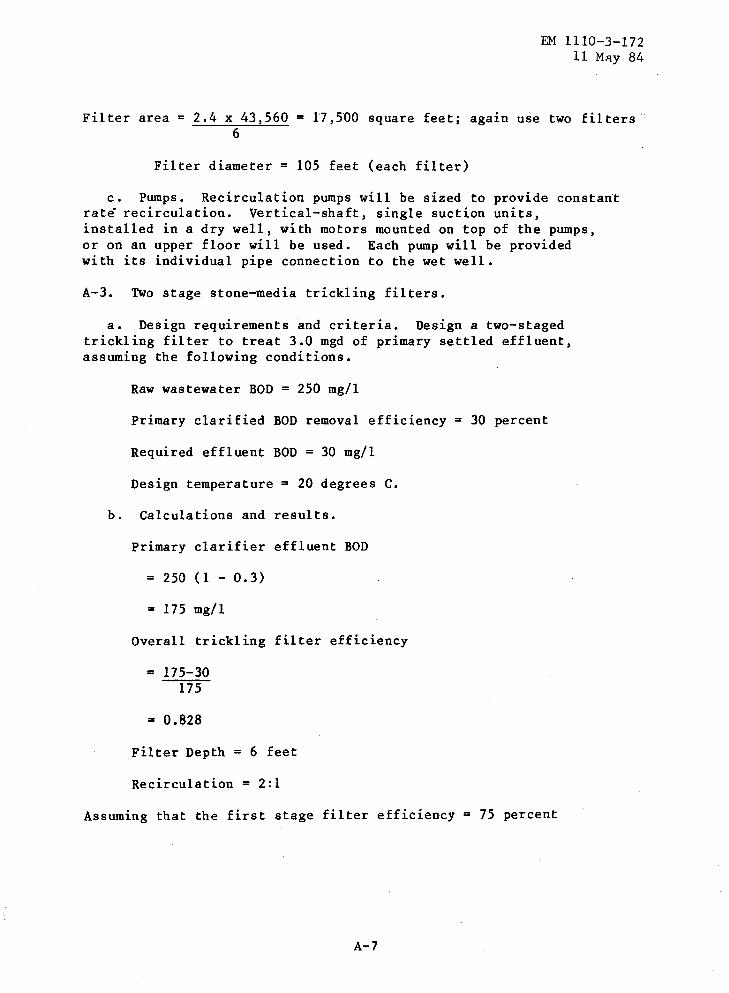
EM 1110-3-172 11 M.<ly 84
Filter area= 2.4 X 43,560 = 17,500 square feet; again use two filters.· 6
Filter diameter = 105 feet (each filter)
c. Pumps. Recirculation pumps will be sized to provide constant rate recirculation. Vertical-shaft, single suction units, installed in a dry well, with motors mounted on top of the pumps, or on an upper floor will be used. Each pump will be provided with its individual pipe connection to the wet well.
A-3. Two stage stone-media trickling filters.
a. Design requirements and criteria. Design a two-staged trickling filter to treat 3.0 mgd of primary settled effluent, assuming the following conditions.
Raw wastewater BOD = 250 mg/1
Primary clarified BOD removal efficiency = 30 percent
Required effluent BOD = 30 mg/1
Design temperature = 20 degrees C.
b. Calculations and results.
Primary clarifier effluent BOD
= 250 (1 - 0.3)
= 175 mg/1
Overall trickling filter efficiency
= 175-30 175
= 0.828
Filter Depth = 6 feet
Recirculation = 2:1
Assuming that the first stage filter efficiency = 75 percent
A-7

EM 1110-3-172 11 May 84
Now
Overall efficiency = 0.828
= 0.75 + E2 (1 - 0.75)
E2 = O.j1
Recirculation factor F = 1 + R (1 + 0.11:{)2
= 1 + 2 = 2.08 (1 + 0,1 X 2)2
Organic loading to first stage filter,
w = 3.0 mgd X 8.34 X 250(1-0.30) = 4,379 use 4,380 pounds/day
using the NRC formula
EI = 1
1 + o.oo85§
1 + 0.0085
V = 1.37 acre feet
pounds/day;
Filter area= 1.37 x 43,560 = 9,946 square feet; 6
Use two filters, 5,000 square feet each
Filter diameter= 79.8 feet, use 80 feet (each filter)
Design second stage filter:
Organic loading, W' = w (1 - 0.75)
= 4,3Sb (1- o.JS)
= 1,095 pounds/day
A-8
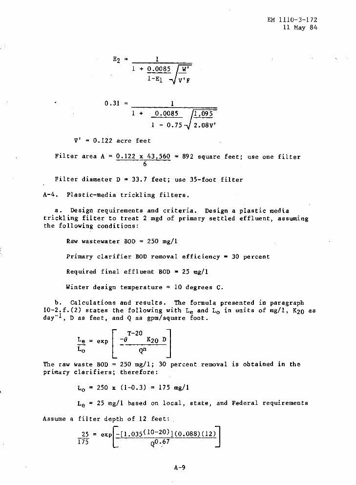
1 +
1
0.008~ [i! l-EI ...jv'F
0.31 = 1 -=-1-+---=-o-. o:-:o:-:8:-::5--;:;I=,=o9=5:::::
1 - 0.75 2.08V'
V' = 0.122 acre feet
EM 1110-3-172 11 May 84
Filter area A= 0.122 x 43,560 = 892 square feet; use one filter 6
Filter diameter D = 33.7 feet; use 35-foot filter
A-4. Plastic-media trickling filters.
a. Design requirements and criteria. Design a plastic media trickling filter to treat 2 mgd of primary settled effluent, assuming the following conditions:
Raw wastewater BOD = 250 mg/1
Primary clarifier BOD removal efficiency = 30 percent
Required final effluent BOD = 25 mg/1
Winter design temperature = 10 degrees c.
b. Calculations and results. The formula presented in paragraph 10-2.f.(2) states the following with Le and 1 0 in units of mg/1, K20 as day-1, D as feet, and Q as gpm/square foot.
exp [
T-20 J -o QnK2o D
The raw waste BOD = 250 mg/1; 30 percent removal is obtained in the primary clarifiers; therefore:
1 0 = 250 x (1-0.3) = 175 mg/1
Le = 25 mg/1 based on local, state, and Federal requirements
Assume a filter depth of 12 feet:
~~ = exp~[l.035(10-20)](0.088)(12)l 175 [ Qo •. 67 j
A-9

EM 1110-3-172 11 May 84
therefore,
0.143 = exp [
-0.78 q0.67J
Taking the natural logarithm of both sides of the equation results as follows:
ln 0.143 =
-1.94 =
-[0.75lln e l90.67 J
-~~:~~ X J.Q
q0.67 = 0.75/1.94
q0.67 = 0.387
Q = ( 0. 387)1.49
= 0.243 gpm/square foot
Required surface area can be computed by:
Surface area Flow Q
2 X 10⁶ gpd Surface Area = --~~1+,~4~4~0-m~i~n~u~t~e~s~/~da~y~--- = 5,716 square feet
0.243 gpm/square foot use 5,720 square feet
Since A = 1r n2 4
1rD2 = 5,120 -4-
D =-) 5, 72~ x 4 = 85.4, use 86 feet
Therefore, the filter dimensions should be:
86 feet diameter by 12 feet deep
Plastic media manufacturers will be consulted to determine the exact proportions of filter media that provides for a minimum of 5,720 square feet area and 12-foot depth.
A-10
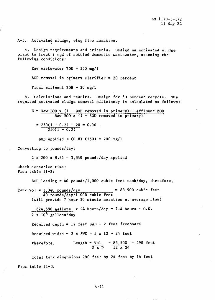
A-5. Activated sludge, plug flow aeration.
EM 1110-3-172 11 May 84
a. Design requirements and criteria. Design an activated sludge plant to treat 2 mgd of settled domestic wastewater, assuming the following conditions:
Raw wastewater BOD = 250 mg/1
BOD removal in primary clarifier = 20 percent
Final effluent Bo• = 20 mg/1
b. Calculations and results. Design for 50 percent recycle. The required activated sludge removal efficiency is calculated as follows:
E = Raw BOD x (1 - BOD removed in primary) - effluent BOD Raw BOD x (1 - BOD removed in primary)
250(1 - 0.2) - 20 = 0.90 250(1- 0.2)
BOD applied = (0.8) (250) = 200 mg/1
Converting to pounds/day:
2 x 200 x 8.34 = 3,340 pounds/day applied
Check detention time: From table 11-2:
BOD loading= 40 pounds/1,000 cubic feet tank/day, therefore,
Tank Vol = 3,340 pounds/day = 83,500 cubic feet 40 pounds/day/1,000 cubic feet
(will provide 7 hour 30 minute aeration at average flow)
624,580 gallons x 24 hours/day= 7.4 hours- O.K. 2 x 10⁶ gallons/day
Required depth = 12 feet SWD + 2 feet freeboard
Required width = 2 x SWD = 2 x 12 = 24 feet
therefore, Length = Vol = 83,500 = 290 feet W X D 12 X 24
Total tank dimensions 290 feet by 24 feet by 14 feet
From table 11-3:
A-ll

EM 1110-3-172 11 May 84
Aeration requirements applied 1,000 cubic feet/pound BOD
= 1,000 .x 3,340 = 3,340,000 cubic feet/day 2,3lq cfm required
The final clarifier is designed on the basis of surface loading equal to 600 gpd/square foot. Assume a depth of 8 feet.
Final clarifier area =
3,333 square feet; use 3,400 square feet
Clarifier diameter = 65 feet
Compute clarifier detention time as a check:
t 3,400 ~~~ 7.48 = 2.4 hours 2 X 10⁶/24
A-6. Activated sludge, completely mixed aeration.
a. Design requirements and criteria. Design a completely mixed aeration tank to treat the same effluent described in example A-5.
b. Calcula tlons and results. From table 11-2, BOD loading = .50 pounds BOD/1,000 cubic feet/day.
Therefore,
Tank Volume 3,340 50/1,000
or, converting to gallons:
66,800 cubic feet
66,800 cubic feet x 7.48 gallons/cubic feet
Check detention time (table 11-2):
500,000 gallons
500,000 gallons x 24 hours/day = 6 hours - O.K. 2 x 10⁶ ~allons/day
Select SWD = 12 feet + 2 foot freeboard
Assume L = 2. Therefore: L x ',J x D = Volume w
Since L = 2W
A-12
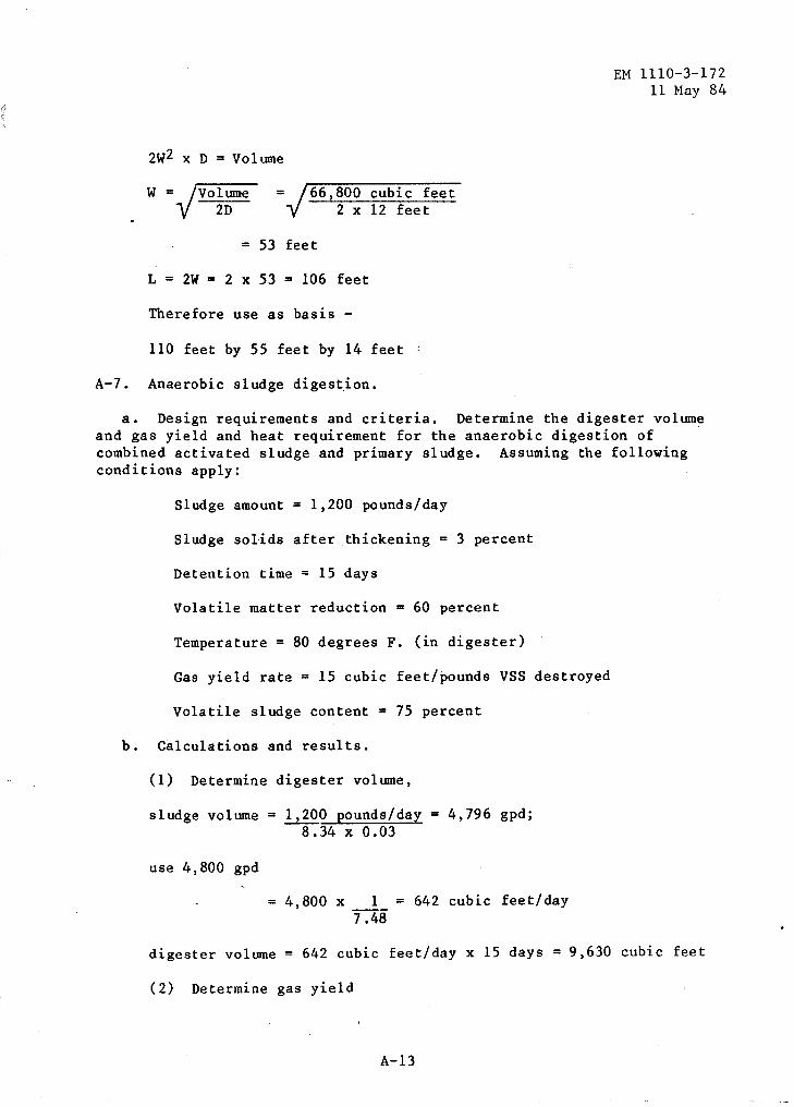
2W2 x D = Volume
W = /Volume V 2D
= 66,800 cubic feet 2 x 12 feet
= 53 feet
L = 2W = 2 x 53 = 106 feet
Therefore use as basis -
110 feet by 55 feet by 14 feet
A-7. Anaerobic sludge digest.ion.
EM 1110-3-172 11 May 84
a. Design requirements and criteria. Determine the digester volume and gas yield and heat requirement for the anaerobic digestion of combined activated sludge and primary sludge. Assuming the following conditions apply:
Sludge amount = 1,200 pounds/day
Sludge solids after thickening = 3 percent
Detention time = 15 days
Volatile matter reduction 60 percent
Temperature = 80 degrees F. (in digester)
Gas yield rate = 15 cubic feet/pounds VSS destroyed
Volatile sludge content = 75 percent
b. Calculations and results.
(1) Determine digester volume,
sludge volume= 1,200 pounds/day= 4,796 gpd; 8.34 X 0.03
use 4,800 gpd
= 4,800 x 1 = 642 cubic feet/day 7.48
digester volume= 642 cubic feet/day x 15 days = 9,630 cubic feet
(2) Determine gas yield
A-13
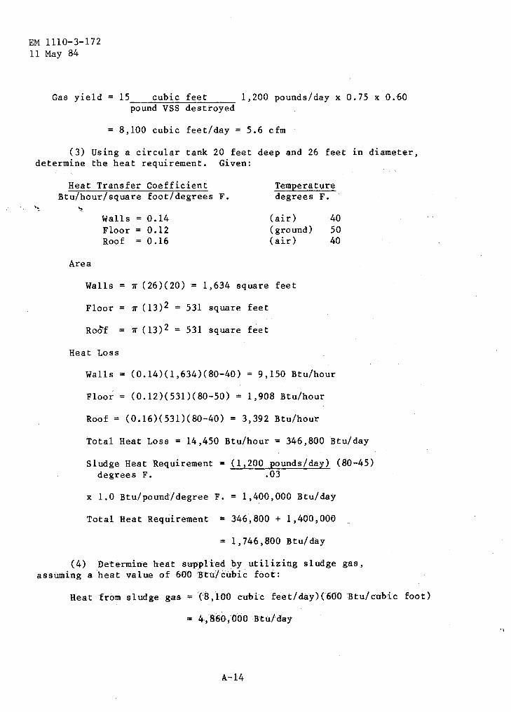
EM 1110-3-1 72 11 May 84
Gas yield 15 cubic feet 1,200 pounds/day x 0.75 x 0.60 pound VSS destroyed
= 8,100 cubic feet/day = 5.6 cfm
(3) Using a circular tank 20 feet deep and 26 feet in diameter, determine the heat requirement. Given:
''!:
Heat Transfer Coefficient TemEerature Btu/hour/ square foot/degrees F. degrees F.
."" Walls 0.14 (air) 40 Floor 0.12 (ground) so Roof 0.16 (air) 40
Area
Walls = 11' (26)(20) = 1,634 square feet
Floor 1r (13)2 = 531 square feet
Ro~f = 11' ( 13)2 = 531 square feet
Heat Loss
Walls= (0.14)(1,634)(80-40) = 9,150 Btu/hour
Floor= (0.12)(531)(80-50) = 1,908 Btu/hour
Roof = (0.16)(531)(80-40) = 3,392 Btu/hour
Total Heat Loss = 14,450 Btu/hour= 346,800 Btu/day
Sludge Heat Requirement degrees F.
= (1,200 Eounds/day) (80-45) .03
x 1.0 Btu/pound/degree F. = 1,400,000 Btu/day
Total Heat Requirement = 346,800 + 1,400,000
= 1, 746,,800 Btu/ day
(4) Determine heat supplied by utilizing sludge gas, assuming a heat value of 600 Btu/cubic foot:
Heat from sludge gas = {8,100 cubic feet/day)(600 Btu/cubic foot)
= 4,860;000 Btu/day
A-14

A-8. Aerobic sludge digestion.
EM 1110-3-172 11 May 84
a. Design requirements and criteria. Determine digester volume and air requirements for the aerobic digestion of activated sludge after thi;kening. Assume the following conditions apply:
Sludge quantity= 1,200 pounds/day
Sludge concentration = 3 percent
Detention time = 20 days
Air supply requirement = 30 cfm/1,000 cubic feet digester volume
b. Calculations and results.
(1) Determine digester volume,
Sludge volume= 1,200 pounds/day= 4,796 gallons/day 8.34 (0.03)
= 4,796 x 1 cubic foot= 641 cubic feet/day 7 .48 gallons
Digester volume = 641 cubic feet/day x 20 days = 12,820 cubic feet
(2) Determine air requirement:
Air required = (12,820 cubic feetH30 cfm/1,000 cubic feet)
= 384.6 cfm; use 385 cfm
(this also satisfies mixing requirements).
A-9. Sludge pumping.
a. Design requirements and criteria. Determine the horsepower and pressure requirements for pumping sludge from a settling tank to a thickener. Assume the following conditions apply:
Sludge is pumped at 6 fps
150 feet of 8 inches pipe is used
Thickener is 10 feet above settling tank (elevation difference = 10 feet)
Sludge specific gravity= 1.02
Sludge moisture content = 95 percent
A-15
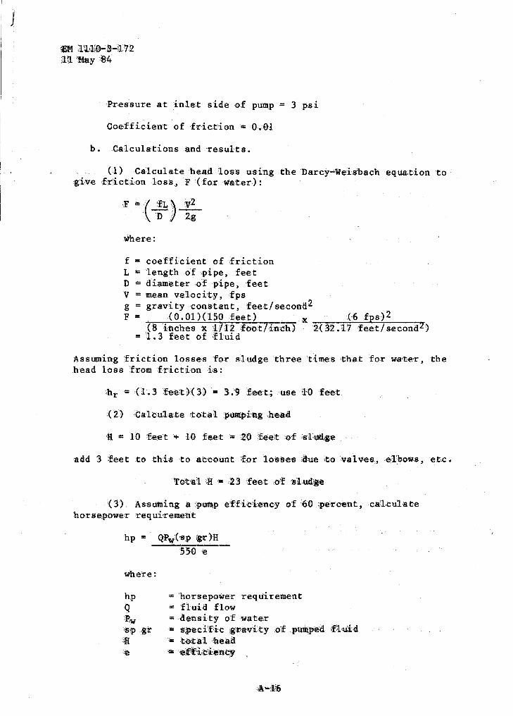
'I J
eM :.Il!I.Q~-~Hl o/:"2. ila iMtty :S4
Pressure at inlet side of pu~p = 3 p.si
Coefficient of fric·tion = 0.01
b. Calculations and results.
0) Calculate 'head loss using the Darcy-Weisbach equa.tion to grve •:friction loss, F :(for wa.ter):
F = ( :.f~ ··)·.·.· V .. 2 ·1).~ ·. . g
~here:
f = coefficient of friction L = length of pipe, feet D = diameter .of pipe, feet V = mean velocity, fps g = gravity constant, feet/second2 F = (0.01)(150 feet) x {6 fps)2
{8 indhes x :1./12 foot/inc:h) 2(32 .17 feet/ second2) = 1 • 3 feet of f1 ui d
Assuming ~friction losses for sludge three times that fo.r wa•ter, the head loss from friction is:
(:3) Assuming a putn:p efficiency o:f ;(>0 ;pe't'cent., ca'kulate horse,powe.r requireme·nt
hp = QPw(·sp •tr )H
5'50 ·e
where:
hp Q Bw iS:p ,gr \l ·~
= horsepower requirement = fluid flow = dertsity of water = sped'fic gttavity of .,putU,{)ed f)l,U.il:l • •tOt-$'1 'heaa • ~rfiit'ien·c:t

Q = (6 fps) (0.333)2 = 2.1 cfs
hp =
(2.1 cfs)(62.4 pcf)(1.02)(23 feet) 550(0.60)
= 9.3 hp; use 10 hp
(4) Determine discharge pump pressure
P = (Total head)(sp gr)(w) 144 square inches/square foot
= (23 feet)(1.02)(62.4 pcf) 144 square inches/square foot
= 10.2 psi
A-10. Chlorinator.
EM 1110-3-172 11 May 84
a. Design requirements and criteria. Determine the capacity of a chlorinator for an activated sludge wastewater treatment plant with an average flow of 2 mgd. The peaking factor for the treatment plant is 2.5. The average required chlorine dosage is 8 mg/1 and the maximum required chlorine dosage is 20 mg/1. EPA regulations require 30-minute contact time at peak hour conditions.
b. Calculations and results.
(1) Determine capacity of the chlorinator at peak flow
pounds Cl2/day = 20 mg/1 x 8.34 pounds/gallon x 2 mgd x 2.5 = 834
Use four 250-pound/day units
(2) Estimate the daily consumption of chlorine.
Average dose = 8 mg/1
(see table 13-1)
pound Cl2/day = 8 X 8.34 X 2.0
= 133.4; use 140
It should be noted that the total unit capacity is about six times the average needed chlorine. This is to cover the peak hydraulic flow of wastewater and to cover a wider. range of dosage of chlorine that might
A-17

1EM fl:il.t0-..:,_lW~ ~u 'May '8'4
be needed under unfavorable conditions. Space requirements for the four units and for storage of chlorine tanks is estimated to be about 400 square feet.
'time. (3) Chlorine contact tank. Required volume fo·r 30-minute contact
Volume = .~ ·x T
Q = .peak filo,w ra'te, gpm T == detention ,t,ime, minutes
Vol = 2.0 x 10⁶ .,gallons/day (2.5)(30 minutes) = 104,170 gallons 1,440 minutes/day
= 13,930 cubic feet; use 14,000 cubic feet
Assume 6 feet SWD + 2 feet freeboard
Let 1 = 10 for c,p1Lu.g flow tank; therefore, w
•L X W X J) = 'Volume
Since L = \H>W, 1tlhe·refore:
ro w2 "" ·:Volume II)
'W = .·Volume ,' __ _ [;() !e D
'l'het:efore, the basic .chlorine contact tank.dimensions are:
153 fee·t by 15.3 feet by 8 feet {6 feet SWD)
Baffling is used to construct a more regular ·tank shape and to prevent flow short-ci:rcuiting. (:Refer to tPA Process Design Manual for Upgrading Existing Wastewi!lter Trei!ltmen:t Plants for layout of tan:k baffles). Using a £low channel width of 15.3 feet and 4 side-'by-side ,plug flow cotnpatttnent:s, the o.verall tank width is:
it93 1~1t <ill: 18 .• ! h'e~t 14

The length is:
4 x 15.3 feet = 61.2 feet
The tank dimensions are therefore:
61.2 feet by 38.3 feet by 8 feet (6 feet SWD)
A-19
EM 1110-3-172 11 May 84
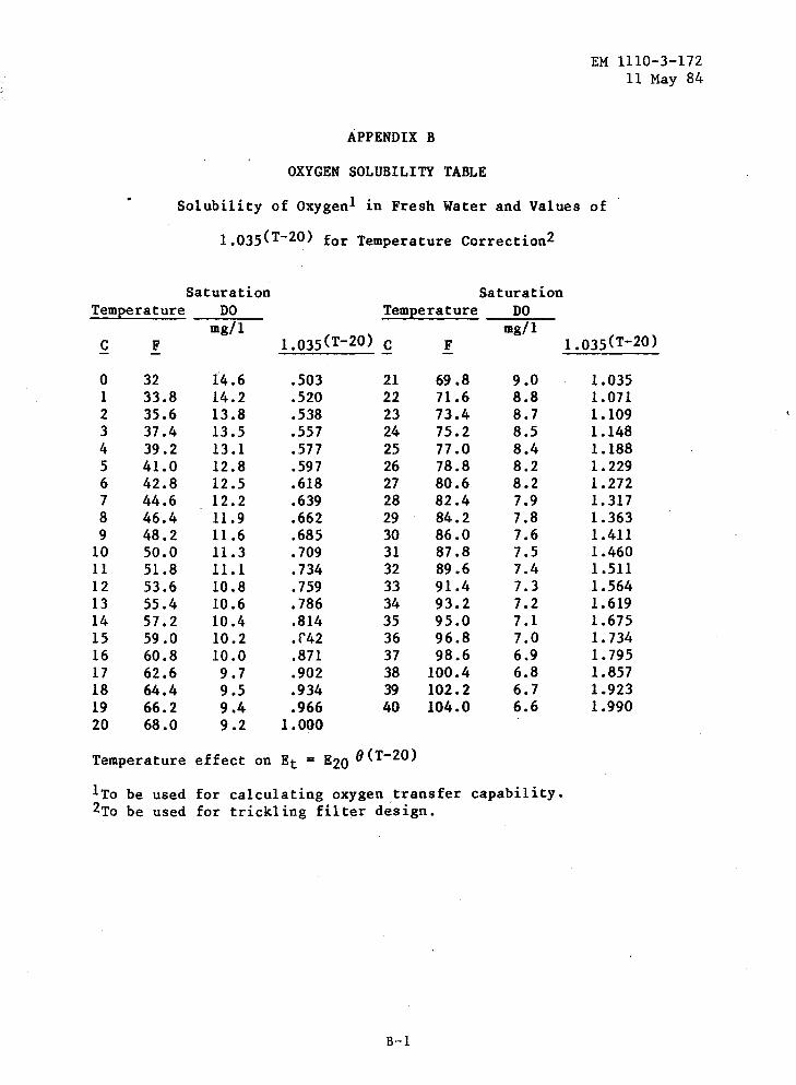
EM 1110-3-172 11 May 84
APPENDIX B
OXYGEN SOLUBILITY TABLE
Solubility of Oxygen1 in Fresh Water and Values of
1.035(T-20) for Temperature Correction2
Saturation Saturation Temeerature DO Temeerature DO
mg/1 1.035(T-20)
mg/1 I.o35 (T-20) c F c F
0 32 14.6 .503 21 69.8 9.0 1.035 1 33.8 14.2 .520 22 71.6 8.8 1.071 2 35.6 13.8 .538 23 73.4 8.7 1.109 3 37.4 13.5 .557 24 75.2 8.5 1.148 4 39.2 13.1 .577 25 77.0 8.4 1.188 5 41.0 12.8 .597 26 78.8 8.2 1.229 6 42.8 12.5 .618 27 80.6 8.2 1.272 7 44.6 12.2 .639 28 82.4 7.9 1.317 8 46.4 11.9 .662 29 84.2 7.8 1.363 9 48.2 11.6 .685 30 86.0 7.6 1.411
10 50.0 11.3 .709 31 87.8 7.5 1.460 11 51.8 11.1 .734 32 89.6 7.4 1.511 12 53.6 10.8 .759 33 91.4 7.3 1.564 13 55.4 10.6 .786 34 93.2 7.2 1.619 14 57.2 10.4 .814 35 95.0 7.1 1.675 15 59.0 10.2 .f42 36 96.8 7.0 1. 734 16 60.8 10.0 .871 37 98.6 6.9 1.795 17 62.6 9.7 .902 38 100.4 6.8 1.857 18 64.4 9.5 .934 39 102.2 6.7 1.923 19 66.2 9.4 .966 40 104.0 6.6 1.990 20 68.0 9.2 1.000
Temperature effect on Et = E20 8(T-20)
1To be used for calculating oxygen transfer capability. 2To be used for trickling filter design.
B-1
Government Publications.
Department of the Army.
AR 40-5
AR 200-1
AR 385-10
EM 1110-3-136
EM 1110-3-174
U.S. Department of Labor.
APPENDIX C
REFERENCES
Health and Environment.
EM 1110-3-172 11 May 84
Environmental Protection and Enhancement.
Army Safety Program.
Drainage and Erosion Control.
Sanitary and Industrial Wastewater Collection.
Occupational Safety and Health, General Industry Standards and Interpretations (October, 1972).
U.S. Environmental Protection Agency (EPA). Superintendent of Documents, U.S. Government Printing Office, Washington, DC 20014
Process Design Manual for Sludge Treatment and Disposal, Technology Transfer Series (October, 1974).
Process Design Manual for Upgrading Existing Wastewater Plants, Technology Transfer Series (January, 1975).
PL 92-500
Nongovernmen~ Publications.
Federal Water Pollution Control Act Amendments of 1972.
American Water Works Association (AWWA), 6666 W. Quincy, Denver, co 80235
Manual No. 3 Safety Practice for Water Utilities (1977).
Hicks, T.G. and Edwards, T.W., Pump Application Engineering, McGraw-Hill, New York, NY, 1971.
The Chlorine Institute (CI), 342 Madison Avenue, New York, NY 10173
C-1
EM 1110,;;.3.;;.172 11 May 84:
Cb1oritte Manual ( 1969') •
Water Poll ufiorr Control Federation (WPCF) ', 26'26 Pennsylvania AV'enue N.W.; washingtori, DC 20037
MattU.a'l o'f Pr~etice No. 1 Sa'fe't1 itt Wastewater Works (191'5).