
JF2 & SE880 UART-SPI-I2C Application Note 80000NT10068A r3 - 2015-04-17

JF2 & SE880 UART-SPI-I2C Application Note
80000NT10068A r3 - 2015-04-17
Reproduction forbidden without written authorization from Telit Communications S.p.A. - All Rights Reserved. Page 2 of 31 Mod. 0809 2011-07 Rev.2
APPLICABILITY TABLE
PRODUCT
JF2
SE880
JF2 & SE880 UART-SPI-I2C Application Note
80000NT10068A r3 - 2015-04-17
Reproduction forbidden without written authorization from Telit Communications S.p.A. - All Rights Reserved. Page 3 of 31 Mod. 0809 2011-07 Rev.2
SPECIFICATIONS SUBJECT TO CHANGE WITHOUT NOTICE
Notice
While reasonable efforts have been made to assure the accuracy of this document, Telit
assumes no liability resulting from any inaccuracies or omissions in this document, or from
use of the information obtained herein. The information in this document has been carefully
checked and is believed to be entirely reliable. However, no responsibility is assumed for
inaccuracies or omissions. Telit reserves the right to make changes to any products described
herein and reserves the right to revise this document and to make changes from time to time
in content hereof with no obligation to notify any person of revisions or changes. Telit does
not assume any liability arising out of the application or use of any product, software, or
circuit described herein; neither does it convey license under its patent rights or the rights of
others.
It is possible that this publication may contain references to, or information about Telit
products (machines and programs), programming, or services that are not announced in your
country. Such references or information must not be construed to mean that Telit intends to
announce such Telit products, programming, or services in your country.
Copyrights
This instruction manual and the Telit products described in this instruction manual may be,
include or describe copyrighted Telit material, such as computer programs stored in
semiconductor memories or other media. Laws in the Italy and other countries preserve for
Telit and its licensors certain exclusive rights for copyrighted material, including the
exclusive right to copy, reproduce in any form, distribute and make derivative works of the
copyrighted material. Accordingly, any copyrighted material of Telit and its licensors
contained herein or in the Telit products described in this instruction manual may not be
copied, reproduced, distributed, merged or modified in any manner without the express
written permission of Telit. Furthermore, the purchase of Telit products shall not be deemed
to grant either directly or by implication, estoppel, or otherwise, any license under the
copyrights, patents or patent applications of Telit, as arises by operation of law in the sale of a
product.
Computer Software Copyrights
The Telit and 3rd Party supplied Software (SW) products described in this instruction manual
may include copyrighted Telit and other 3rd Party supplied computer programs stored in
semiconductor memories or other media. Laws in the Italy and other countries preserve for
Telit and other 3rd Party supplied SW certain exclusive rights for copyrighted computer
programs, including the exclusive right to copy or reproduce in any form the copyrighted
computer program. Accordingly, any copyrighted Telit or other 3rd Party supplied SW
computer programs contained in the Telit products described in this instruction manual may
not be copied (reverse engineered) or reproduced in any manner without the express written
permission of Telit or the 3rd Party SW supplier. Furthermore, the purchase of Telit products
shall not be deemed to grant either directly or by implication, estoppel, or otherwise, any
license under the copyrights, patents or patent applications of Telit or other 3rd Party supplied
SW, except for the normal non-exclusive, royalty free license to use that arises by operation
of law in the sale of a product.

JF2 & SE880 UART-SPI-I2C Application Note
80000NT10068A r3 - 2015-04-17
Reproduction forbidden without written authorization from Telit Communications S.p.A. - All Rights Reserved. Page 4 of 31 Mod. 0809 2011-07 Rev.2
Usage and Disclosure Restrictions
License Agreements
The software described in this document is the property of Telit and its licensors. It is
furnished by express license agreement only and may be used only in accordance with the
terms of such an agreement.
Copyrighted Materials
Software and documentation are copyrighted materials. Making unauthorized copies is
prohibited by law. No part of the software or documentation may be reproduced, transmitted,
transcribed, stored in a retrieval system, or translated into any language or computer language,
in any form or by any means, without prior written permission of Telit
High Risk Materials
Components, units, or third-party products used in the product described herein are NOT
fault-tolerant and are NOT designed, manufactured, or intended for use as on-line control
equipment in the following hazardous environments requiring fail-safe controls: the operation
of Nuclear Facilities, Aircraft Navigation or Aircraft Communication Systems, Air Traffic
Control, Life Support, or Weapons Systems (High Risk Activities"). Telit and its supplier(s)
specifically disclaim any expressed or implied warranty of fitness for such High Risk
Activities.
Trademarks
TELIT and the Stylized T Logo are registered in Trademark Office. All other product or
service names are the property of their respective owners.
Copyright © Telit Communications S.p.A. 2015.

JF2 & SE880 UART-SPI-I2C Application Note
80000NT10068A r3 - 2015-04-17
Reproduction forbidden without written authorization from Telit Communications S.p.A. - All Rights Reserved. Page 5 of 31 Mod. 0809 2011-07 Rev.2
Contents
1. Introduction ................................................................................................................... 8
1.1. Scope ....................................................................................................................... 8
1.2. Audience .................................................................................................................. 8
1.3. Contact Information, Support ................................................................................... 8
1.4. Text Conventions ..................................................................................................... 9
1.5. Related Documents .................................................................................................. 9
2. Overview ...................................................................................................................... 10
2.1. Message Protocols ................................................................................................. 10
3. Host Port Implementation .......................................................................................... 11
3.1. Configuration Setting .............................................................................................. 11
3.1.1. Host Port Type Selection ........................................................................................... 12
3.2. Host Port Pin Identification and Logic Levels ......................................................... 12
3.2.1. Host Port Pin Identification ......................................................................................... 12
3.2.2. Host Port Logic Levels ............................................................................................... 13
3.3. Data Ready Indicator Pin ....................................................................................... 13
3.4. Data Rates and Timing Considerations .................................................................. 13
3.4.1. Input to the JF2 /SE880 ............................................................................................. 13
3.4.2. Output from the JF2 / SE880 ..................................................................................... 14
4. UART............................................................................................................................ 15
4.1. UART Flow Control ................................................................................................ 15
4.1.1. No hardware flow control ........................................................................................... 15
4.1.2. Hardware flow control ................................................................................................ 15
4.2. UART Operation ..................................................................................................... 16
4.2.1. UART TX/RX Electrical .............................................................................................. 16
4.2.2. UART Frame Format ................................................................................................. 16
4.2.3. UART Data rates ....................................................................................................... 16
4.3. UART Internal Details ............................................................................................ 17
5. I2C ................................................................................................................................. 18
5.1. I2C Description ....................................................................................................... 18
5.1.1. I2C Electrical .............................................................................................................. 18
5.1.2. I2C Frame Format ...................................................................................................... 19
5.1.3. I2C Considerations ..................................................................................................... 19

JF2 & SE880 UART-SPI-I2C Application Note
80000NT10068A r3 - 2015-04-17
Reproduction forbidden without written authorization from Telit Communications S.p.A. - All Rights Reserved. Page 6 of 31 Mod. 0809 2011-07 Rev.2
5.2. I2C Operation ......................................................................................................... 19
5.2.1. I2C Data Rates ........................................................................................................... 19
5.2.2. I2C Addresses ............................................................................................................ 20
5.2.3. I2C Message transfer ................................................................................................. 20
5.3. I2C Details ............................................................................................................. 20
6. SPI ................................................................................................................................ 21
6.1. SPI Description ...................................................................................................... 21
6.1.1. SPI Clock polarity and phase ..................................................................................... 21
6.1.2. SPI Considerations .................................................................................................... 22
6.2. SPI Operation ......................................................................................................... 23
6.2.1. SPI Initialization ......................................................................................................... 23
6.2.2. SPI Message Transfer ............................................................................................... 23
6.3. SPI Internal Details ................................................................................................ 24
6.4. SPI Example Communications ............................................................................... 24
7. I2C and SPI Communications Testing ....................................................................... 26
7.1. I2C .......................................................................................................................... 27
7.2. SPI ......................................................................................................................... 29
8. Document History ....................................................................................................... 31
JF2 & SE880 UART-SPI-I2C Application Note
80000NT10068A r3 - 2015-04-17
Reproduction forbidden without written authorization from Telit Communications S.p.A. - All Rights Reserved. Page 7 of 31 Mod. 0809 2011-07 Rev.2
Figures
Figure 5-1 I2C Required Pullups ...................................................................................................... 18 Figure 6-1 SPI Master-Slave Connection ........................................................................................ 21 Figure 6-2 Example Startup Dialog ................................................................................................. 24 Figure 6-3 Example NMEA message .............................................................................................. 25 Figure 7-1 AARDVARK SPI/12C to USB ......................................................................................... 26 Figure 7-2 Configure Aardvark Adapter ........................................................................................... 27 Figure 7-3 Select an Aardvark port.................................................................................................. 27 Figure 7-4 Confirms successful 12C communications ..................................................................... 28 Figure 7-5 Aardvark 12C/SPI Control Center MOSI Message ......................................................... 29
Tables
Table 3-1 Host Port Type Selection ................................................................................................. 12 Table 3-2 Host Port Pin Identification .............................................................................................. 12 Table 6-1 SPI Modes of Operation .................................................................................................. 22 Table 6-2 OK-to-Send Message ...................................................................................................... 25

JF2 & SE880 UART-SPI-I2C Application Note
80000NT10068A r3 - 2015-04-17
Reproduction forbidden without written authorization from Telit Communications S.p.A. - All Rights Reserved. Page 8 of 31 Mod. 0809 2011-07 Rev.2
1. Introduction
1.1. Scope
Scope of this document is to give an overview of communication interfaces available in the
GPS module Jupiter JF2 and Jupiter SE880.
1.2. Audience
This document is intended for customers who are developing applications with JF2 or SE880
using the serial interface.
1.3. Contact Information, Support
For general contact, technical support, to report documentation errors and to order manuals,
contact Telit Technical Support Center (TTSC) at:
Alternatively, use:
http://www.telit.com/en/products/technical-support-center/contact.php
For detailed information about where you can buy the Telit modules or for recommendations
on accessories and components visit:
http://www.telit.com
To register for product news and announcements or for product questions contact Telit
Technical Support Center (TTSC).
Our aim is to make this guide as helpful as possible. Keep us informed of your comments and
suggestions for improvements.
Telit appreciates feedback from the users of our information.

JF2 & SE880 UART-SPI-I2C Application Note
80000NT10068A r3 - 2015-04-17
Reproduction forbidden without written authorization from Telit Communications S.p.A. - All Rights Reserved. Page 9 of 31 Mod. 0809 2011-07 Rev.2
1.4. Text Conventions
Danger – This information MUST be followed or catastrophic equipment failure or bodily
injury may occur.
Caution or Warning – Alerts the user to important points about integrating the module, if
these points are not followed, the module and end user equipment may fail or malfunction.
Tip or Information – Provides advice and suggestions that may be useful when
integrating the module.
All dates are in ISO 8601 format, i.e. YYYY-MM-DD.
1.5. Related Documents
JF2 Product Description, 80403ST10103A
JF2 Hardware User Guide, 1vv0300985
JF2 EVK User Guide, 1vv0300987
SE880 Product User Guide
SE880 EVK User Guide
Telit SS4 NMEA Reference Guide
Telit SS4 OSP Interface Control Document

JF2 & SE880 UART-SPI-I2C Application Note
80000NT10068A r3 - 2015-04-17
Reproduction forbidden without written authorization from Telit Communications S.p.A. - All Rights Reserved. Page 10 of 31 Mod. 0809 2011-07 Rev.2
2. Overview
This document describes the operation of the serial interfaces on the JF2 and SE880 modules.
At start-up, the Host port can be configured for one of the three types of communications
interfaces:
UART
I2C
SPI
This is done by sensing the state of 2 pins at start up.
The serial port outputs are 1.8V logic levels, while the inputs are 1.8V to 3.6V tolerant.
2.1. Message Protocols
Two message protocols are supported:
NMEA as described in the NMEA Reference Guide
OSP as described in the One Socket Protocol Interface Control Document
The system does not support concurrent operation of NMEA and OSP on the same serial port.
Either of these protocols can be used with any of the three communications interfaces (UART,
I2C, or SPI)
Refer to documentation available under Non-Disclosure Agreement (NDA) for features and
functions of the modules which have critical reliance on proper operation of the serial port
interfaces:
NMEA Message Protocol
OSP Messaging Protocol
SGEE Downloader
Host Data storage for SGEE, CGEE, and BE
JF2 & SE880 UART-SPI-I2C Application Note
80000NT10068A r3 - 2015-04-17
Reproduction forbidden without written authorization from Telit Communications S.p.A. - All Rights Reserved. Page 11 of 31 Mod. 0809 2011-07 Rev.2
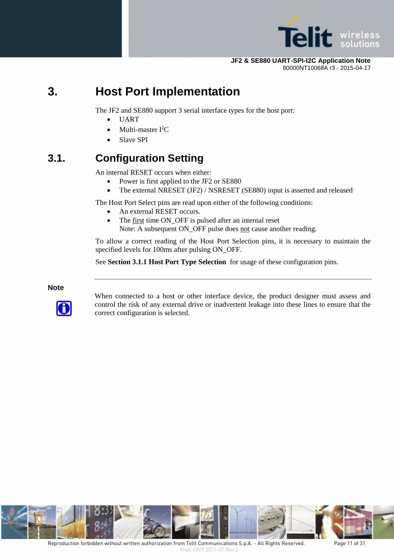
3. Host Port Implementation
The JF2 and SE880 support 3 serial interface types for the host port:
UART
Multi-master I2C
Slave SPI
3.1. Configuration Setting
An internal RESET occurs when either:
Power is first applied to the JF2 or SE880
The external NRESET (JF2) / NSRESET (SE880) input is asserted and released
The Host Port Select pins are read upon either of the following conditions:
An external RESET occurs.
The first time ON_OFF is pulsed after an internal reset
Note: A subsequent ON_OFF pulse does not cause another reading.
To allow a correct reading of the Host Port Selection pins, it is necessary to maintain the
specified levels for 100ms after pulsing ON_OFF.
See Section 3.1.1 Host Port Type Selection for usage of these configuration pins.
Note When connected to a host or other interface device, the product designer must assess and
control the risk of any external drive or inadvertent leakage into these lines to ensure that the
correct configuration is selected.

JF2 & SE880 UART-SPI-I2C Application Note
80000NT10068A r3 - 2015-04-17
Reproduction forbidden without written authorization from Telit Communications S.p.A. - All Rights Reserved. Page 12 of 31 Mod. 0809 2011-07 Rev.2
3.1.1. Host Port Type Selection
This table indicates the required state of the host port type selection pins during the startup
sequence to select the desired communication mode.
JF2 pin SE880
pin
Pullup /
Pulldown
UART I2C
(multi-master)
SPI
(slave)
23
GPIO6
31
CTS_SPI
Weak
internal
pulldown
Pullup
(10 kΩ to +1.8 V)
Float Float
(becomes SPI CLK)
24
GPIO7
32
RTS_SPI
Weak
internal
pullup
Float Pulldown
(10 kΩ to ground)
Float
(becomes SPI_CS)
Table 3-1 Host Port Type Selection
3.2. Host Port Pin Identification and Logic Levels
3.2.1. Host Port Pin Identification
This table indicates the signals for the host port pins after host port selection is done.
JF2 Pin
SE880 Pin
Interface signal names
UART I2C (multi-master) SPI (slave)
10 : TX 33 : TX TX SCL (I2C_CLK) 3 SSPI_DO MISO
11 : RX 34 : RX RX SDA (I2C_DATA) 3 SSPI_DI MOSI
23
GPIO6 1
31
CTS_SPI 1
Not Used
or may be CTS 2
Not Used
SSPI_CLK
(SPI slave clock input)
24
GPIO7
32
RTS_SPI
Not Used
or may be RTS 2
Not Used
SSPI_CS
(SPI select – active low)
Note 1: GPIO6 / CTS_SPI and GPIO7 / RTS_SPI may require pullups or pulldowns during startup to
select the port type. See Table 3-1 Host Port Type Selection.
Note 2: See Section 4.1 UART Flow Control.
Note 3: The I2C protocol requires pullups on SCL and SDA.See Section 5.1.1 I2C Electrical
Table 3-2 Host Port Pin Identification

JF2 & SE880 UART-SPI-I2C Application Note
80000NT10068A r3 - 2015-04-17
Reproduction forbidden without written authorization from Telit Communications S.p.A. - All Rights Reserved. Page 13 of 31 Mod. 0809 2011-07 Rev.2
3.2.2. Host Port Logic Levels
Serial outputs are CMOS 1.8V levels and may require an external level shifter to interface
with a 3.3 V Host input.
Input pins are 3.3 V compatible. However, if serial Input is driven from a source higher than
1.8 V, excess leakage current may flow through the ~80 kΩ internal pull-up resistor
3.3. Data Ready Indicator Pin
This pin is not functional unless a correct Firmware version is installed.
Contact Telit support for details for using this signal.
GPIO3 can be used as a message-ready indicator to simplify host interfacing. If there is no
data to transmit, GPIO3 stays low. GPIO3 goes high when data is ready to be sent out, and
after completion of all data transmission, it goes low again.
It is supported in two modes:
UART with Flow control enabled
SPI slave
Note: GPIO3 is also used for other purposes depending on firmware, e.g. antenna sense.
3.4. Data Rates and Timing Considerations
3.4.1. Input to the JF2 /SE880
The serial port is ready about 150 ms after the baseband has been started with an ON_OFF
pulse, at which time an OK to SEND message (NMEA message $PSRF150,1 or OSP
Message ID 18) is transmitted.
Input commands are generally processed within 200 ms of receipt.
Commands can be sent continuously but at least one second must be allowed for their
processing.
The maximum sustained command input is about 10,000 characters per second. Therefore, the
full bandwidth should not be utilized at rates above 115.2 kbps. Command processing is a low
priority task within the system.
At higher data rates, TELIT recommends using OSP message/ACK protocol to prevent
message loss.
The module can support serial port operation at speeds above 115.2 kbps for data download
of EE files, ROM patches, and loading flash memory.

JF2 & SE880 UART-SPI-I2C Application Note
80000NT10068A r3 - 2015-04-17
Reproduction forbidden without written authorization from Telit Communications S.p.A. - All Rights Reserved. Page 14 of 31 Mod. 0809 2011-07 Rev.2
Low data rates impact startup and TTFF times in sending configuration commands, EE data,
and patches to ROM-based devices and when using host storage for data files.
For example, downloading a single EE data block for one satellite in NMEA at 4.8 kbps, will
take about ½ second. Refer to EE documentation for the sizes of various messages and files.
Low data rates will also impact the time taken to apply patches to ROM-based devices. Refer
to the Patch Manager documentation for the sizes of various messages and files.
3.4.2. Output from the JF2 / SE880
Selection and rate of delivery of some output messages can be configured via OSP or NMEA
commands
Debug messages are controlled as a block and cannot be individually selected.
Messages associated with request and transfer of EE data between host and the module may
not be configurable.
Some event or alarm messages occur spontaneously and cannot be directly controlled.
The designer must assess the capacity of the communications link between the module and
the host. Select OSP or NMEA messages appropriate to the application and well within the
maximum capacity of the communications link. In assessing the capacity required, consider
the protocol overheads and maximum size of variable payloads.
For example, NMEA GSV sentence can range from an empty single message about 20
characters long including header and ender, to three consecutive messages of about 80
characters each.
In applications where power consumption is critical, time spent creating and sending
messages causes both the module and the host to consume power. A low data link speed
increases the current consumption during data transmission.
When switching the unit to hibernate mode using orderly shutdown with ON_OFF pulse or by
OSP/NMEA command message, the module will continue to run until the transmit/output
buffers are emptied.
At slow serial port speeds with a high volume of data, time-to-turn-off may be up to one
second.
If host flow control prevents output of final messages, the module will not turn off.

JF2 & SE880 UART-SPI-I2C Application Note
80000NT10068A r3 - 2015-04-17
Reproduction forbidden without written authorization from Telit Communications S.p.A. - All Rights Reserved. Page 15 of 31 Mod. 0809 2011-07 Rev.2
4. UART
UART is commonly used for GPS data reporting and receiver control.
UART features include:
Transmit and receive channels contain a 64 Byte FIFO
Serial data rates are selectable from 1200 baud to 1.2288 Mbps
4.1. UART Flow Control
4.1.1. No hardware flow control
Only RX and TX data lines are used.
No hardware or software flow control is available.
4.1.2. Hardware flow control
Note: This configuration is not available in all firmware versions.
Hardware flow control may be configured via an OSP command.
RX and TX lines are used for data transmission.
RTS and CTS for hardware flow control are available:
When CTS is low, transmission stops at the end of the current character.
It restarts when CTS goes high.
Note that module may lose or garble serial messages if host flow control throttling is too
severe. System design assumes unrestricted outflow of serial messages.
JF2 & SE880 UART-SPI-I2C Application Note
80000NT10068A r3 - 2015-04-17
Reproduction forbidden without written authorization from Telit Communications S.p.A. - All Rights Reserved. Page 16 of 31 Mod. 0809 2011-07 Rev.2
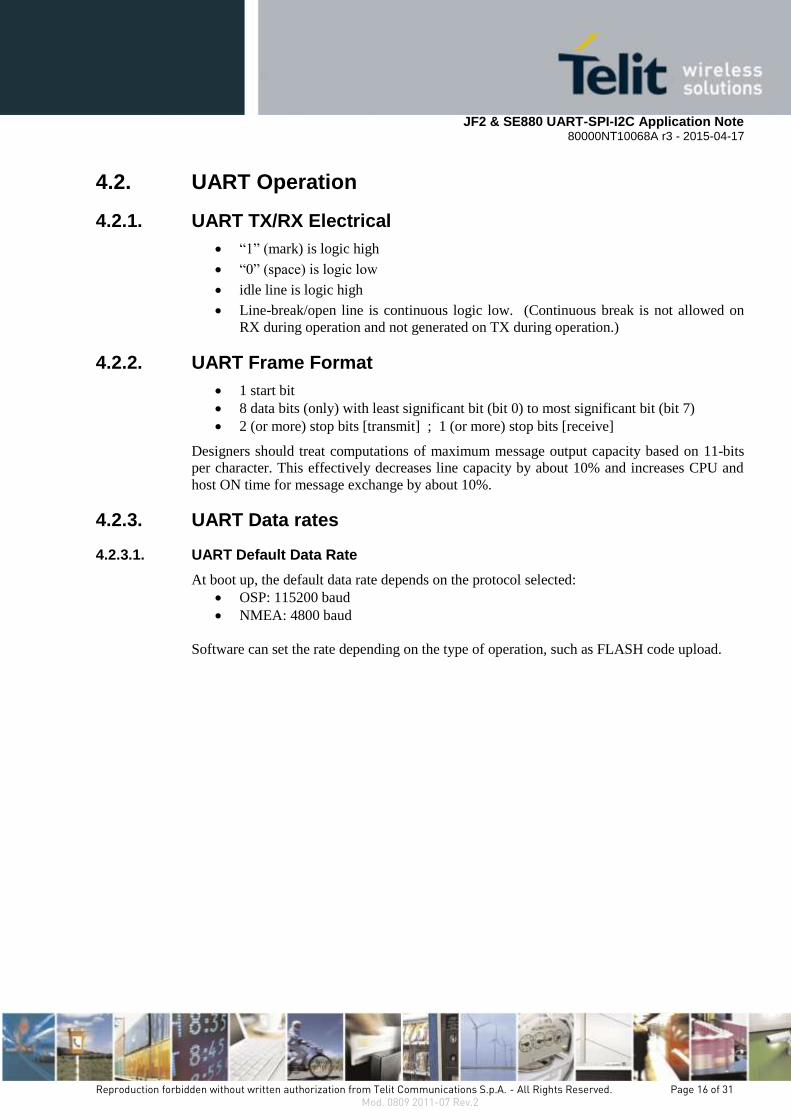
4.2. UART Operation
4.2.1. UART TX/RX Electrical
“1” (mark) is logic high
“0” (space) is logic low
idle line is logic high
Line-break/open line is continuous logic low. (Continuous break is not allowed on
RX during operation and not generated on TX during operation.)
4.2.2. UART Frame Format
1 start bit
8 data bits (only) with least significant bit (bit 0) to most significant bit (bit 7)
2 (or more) stop bits [transmit] ; 1 (or more) stop bits [receive]
Designers should treat computations of maximum message output capacity based on 11-bits
per character. This effectively decreases line capacity by about 10% and increases CPU and
host ON time for message exchange by about 10%.
4.2.3. UART Data rates
4.2.3.1. UART Default Data Rate
At boot up, the default data rate depends on the protocol selected:
OSP: 115200 baud
NMEA: 4800 baud
Software can set the rate depending on the type of operation, such as FLASH code upload.

JF2 & SE880 UART-SPI-I2C Application Note
80000NT10068A r3 - 2015-04-17
Reproduction forbidden without written authorization from Telit Communications S.p.A. - All Rights Reserved. Page 17 of 31 Mod. 0809 2011-07 Rev.2
4.2.3.2. UART Selectable Data Rates
Not all possible data rates are supported by every firmware version.
UART data rates are: 4.8, 9.6, 19.2, 38.4, 57.6, 115.2, 230.4, 460.8, 921.6 and 1228.8 kbps.
Higher data rates can be configured, but have not been tested.
Operation at rates above 115.2 kbps have not been rigorously tested and verified.
Because UART transmission is asynchronous and sampled by the receiver, both sender and
receiver require closely matched bit-rate clocks.
Data bit waveform and timing distortion must be limited.
Maximum allowed clock rate difference between the module and the host is 2.0% overall.
Maximum bit-edge distortion is 5% UI and maximum bit jitter is 5% UI.
Unit Interval (UI) = ( 1 / data bit rate )
4.3. UART Internal Details
The following internal operation details are provided for information only:
Internal FIFOs: RX 64 bytes, TX 64 bytes
Start bit detection: 1 → 0 edge transition and sample at ½ UI of start bit time
False start bit detection: After 1 → 0 edge detection, sample must be 0 at ½ start bit time
Interrupts for RX input FIFO not empty and TX FIFO refill level reached
UART sampling rate is RTC*3340/2. The resulting error between nominal UART bit
clocking rate and actual JF2 bit clocking rate can be determined as:
where RTC is nominal 32.768000 kHz but may vary by +25 ppm /-200 ppm

JF2 & SE880 UART-SPI-I2C Application Note
80000NT10068A r3 - 2015-04-17
Reproduction forbidden without written authorization from Telit Communications S.p.A. - All Rights Reserved. Page 18 of 31 Mod. 0809 2011-07 Rev.2
5. I2C
The module supports two-wire I2C operation in multi-master mode only, with behavior
similar to UART operation. Refer to industry documents on I2C interfaces and operation.
5.1. I2C Description
5.1.1. I2C Electrical
All device drivers are specified as open drain with external pull-up to allow collision
detection and contention resolution.
Figure 5-1 I2C Required Pullups
* Note, for proper operation, external pull-ups are required to ensure proper rise times with
stray shunt capacitances from attached loads and traces. These must be pulled up to 1.8V-
3.6V supply. The typical resistor value is between 1KΩ and 2.2KΩ.

JF2 & SE880 UART-SPI-I2C Application Note
80000NT10068A r3 - 2015-04-17
Reproduction forbidden without written authorization from Telit Communications S.p.A. - All Rights Reserved. Page 19 of 31 Mod. 0809 2011-07 Rev.2
5.1.2. I2C Frame Format
I2C-standard 8-bit octets (bytes) are used. Bit order is MSB transmitted first, with the first
byte of a transfer containing the 7-bit address and direction bit per the standard. The direction
bit is set to ‘0’ indicating write or send in all transfers involving the module. There is no
specified maximum limit of bytes per transfer.
5.1.3. I2C Considerations
Note that the module may lose or garble serial messages if contention with other bus masters
makes it unable to send all messages. System design assumes unrestricted outflow of serial
messages.
When switching the module to hibernate mode using orderly shutdown with ON_OFF pulse
or by OSP/NMEA command message, it will continue to run until the I2C transmit buffers are
emptied.
At slow I2C serial port speeds with a high volume of data, time-to-turn-off may be up to one
second with no throttling from contention.
If multi-master mode contention on the I2C bus prevents output, the module will take longer
to turn off. If the I2C bus is inadvertently seized (another device hold clocks or data line low
and never releases) the module will not turn off.
Note: On the SE880, the I2C port should not be confused with the secondary I2C port (which
is reserved for external serial EEPROM, Serial Flash, and MEMS sensors).
5.2. I2C Operation
5.2.1. I2C Data Rates
The supported bit clock rates are 100 kbps (standard mode) and 400 kbps (DEFAULT - fast
mode). High speed mode is not supported. The data rate can be changed using an OSP
command (MID 178, SID 2).
The maximum I2C data handling capacity between sender and receiver must be de-rated by
protocol overheads, collision density, and backoff/retry timing.
JF2 & SE880 UART-SPI-I2C Application Note
80000NT10068A r3 - 2015-04-17
Reproduction forbidden without written authorization from Telit Communications S.p.A. - All Rights Reserved. Page 20 of 31 Mod. 0809 2011-07 Rev.2
5.2.2. I2C Addresses
Address format is 7-bit. I2C supports multiple masters and multiple slaves.
When the module is the master, it addresses the host CPU at the address 0x62.
When the host is master, the module responds to address 0x60.
The module’s I2C master and slave addresses can be changed under firmware control using
OSP command (MID 178, SID 2).
5.2.3. I2C Message transfer
Multi-master mode requires that the hardware detect and arbitrate between collisions for
master status and data direction. Master or slave mode is determined from clock contention:
whichever device is generating the clock is master, and all other devices on the bus are slave.
In the event of contention time-out, the master device must take control of error detection and
retries. If a device has data to send, it waits for the bus to idle, then asserts itself as master
and sends the data.
Thus in a typical application the module periodically asserts itself as bus master and sends
messages to the host. If the host wants to send a command to the module, it must assert itself
as master when the I2C bus becomes idle, and then send the command. If the module has a
response to the command, it becomes the master again and sends the reply.
If both the module and the host try to assert bus mastership at the same time, the module
executes the contention resolution mechanism specified by the I2C standard.
5.3. I2C Details
The following internal operation details are provided for information only:
Internal FIFOs for RX and TX are 64 bytes.
Bus contention timeout is set to 30 ms and is not changeable.

JF2 & SE880 UART-SPI-I2C Application Note
80000NT10068A r3 - 2015-04-17
Reproduction forbidden without written authorization from Telit Communications S.p.A. - All Rights Reserved. Page 21 of 31 Mod. 0809 2011-07 Rev.2
6. SPI
Firmware currently supports only the SPI format, not MicroWire.
The module operates only as SPI slave. This requires that the host drive the SPI clock and SPI
chip select lines when it wishes to receive messages from the module.
The maximum clock frequency supported is 6.8MHz.
Daisy chain or “cascaded” clock mode is not supported.
Frame size is 8 bits, with MSB sent first.
There are no unique SPI headers; the payload is the same structure as the message.
NMEA messages and OSP messages each have their own unique start-of-message, end-of
message patterns and message data structures.
All channel recovery, message sequencing, and integrity checks are the responsibility of the
SPI master.
6.1. SPI Description
SCK
SDI
SDO
nSE
SPI
Master
SPI
Slave
SCK
SDO
SDI
nSE
Figure 6-1 SPI Master-Slave Connection
The four SPI pins are:
SPI Data Input (Master Out, Slave In - MOSI)
SPI Data Output (Master In, Slave Out - MISO)
SPI Select Input
SPI Clock Input
6.1.1. SPI Clock polarity and phase
There are four modes of communication between the master and slave depending on the clock
polarity and clock phase with respect to data.
CPOL defines the polarity of clock and CPHA defines the clock phase.
When CPOL is zero, the clock stays low and the status of clock phase is determined by
CPHA.
If CPHA is zero, data is read on the clock's rising edge and changed on a falling edge.
If CPHA is high, data is read on the clock's falling edge and changed on a rising edge.

JF2 & SE880 UART-SPI-I2C Application Note
80000NT10068A r3 - 2015-04-17
Reproduction forbidden without written authorization from Telit Communications S.p.A. - All Rights Reserved. Page 22 of 31 Mod. 0809 2011-07 Rev.2
When CPOL is one, it is opposite of when the CPOL is zero. The clock stays high in the idle
state.
If CPHA is zero, data is read on clock's falling edge and data is changed on a rising edge.
If CPHA is one, data is read on clock's rising edge and data is changed on a falling edge
It is important that the CPOL and CPHA match between the master and slave. These are set in
the module by default to CPOL = 0, CPHA = 1, and cannot be changed under normal
circumstances. The combinations of polarity and phase are often referred to as modes, which
are commonly numbered according to the following convention:
Mode CPOL CPHA Comments
0 0 0 Not supported
1 0 1 Supported
2 1 0 Not supported
3 1 1 Supported (requires custom software)
Table 6-1 SPI Modes of Operation
Please note that only 2 modes out of four are supported, and to change from default mode 1 to
mode 3 requires special software from Telit.
6.1.2. SPI Considerations
When the serial interface is configured for SPI mode, the internal framing logic is powered up
in the hibernate state. Accidental toggling of the SPI clock line while SSPI_CS is enabled will
step the framing register requiring software logic on the host to recover frame synch.
When switching to the hibernate state using orderly shutdown (with an ON_OFF pulse or by
command), the module will continue to run until the SPI transmit/output buffers are emptied.
At slow serial port speeds with a high volume of data, time-to-turn-off may be up to one
second.
If the host stops polling or turns off the SPI clock before the TX FIFO is empty and idle
patterns are sent to host, the module will never turn off.

JF2 & SE880 UART-SPI-I2C Application Note
80000NT10068A r3 - 2015-04-17
Reproduction forbidden without written authorization from Telit Communications S.p.A. - All Rights Reserved. Page 23 of 31 Mod. 0809 2011-07 Rev.2
6.2. SPI Operation
6.2.1. SPI Initialization
In order to communicate properly between SPI devices, the exact protocol must be agreed on,
including the SPI mode and an idle byte pattern. The master can periodically transmit the idle
pattern (A7B4) and poll the module for the same pattern. This indicates that the slave is ready
to communicate, but has nothing to transmit. After power up, the module will transmit the OK
to SEND message after about 150 ms, indicating that the module is ready to receive.
6.2.2. SPI Message Transfer
To begin a communication, the master pulls the SPI Chip Select (SPI_CS) pin low and
generates a clock frequency (less than or equal to the maximum frequency supported by the
slave device). During clock generation, full duplex transmission occurs:
the master sends data on its SDO (MOSI) line; the slave reads from its SDI line
the slave sends data on its SDO (MISO) line; the master reads from its SDI line
Each device transmits Idle characters when it has no data to send.
The host (master) is expected to transmit the idle pattern when it is querying the module,
unless it has messages to transmit. This keeps processing overhead low since hardware does
not place most idle pattern bytes in the RX FIFO.
Most messaging from the module can be serviced by polling. Since message creation times
may have about 200 ms of jitter from second-to-second, the host must start polling before
messages are expected from the module. Any delay in polling increases the latency between
position fix calculation and position fix reception by the host.
The Data Ready Indicator pin may be used as “message waiting” to signal the host that the
module has data to send, and polling should be started. This indicator is unaffected by idle
byte pattern.
When transmitting, the module fills its FIFO with as many queued up messages as it can fit.
The host is required to poll messages until idle pattern bytes are detected. The module then
replenishes its TX-FIFO with subsequent pending messages (if any).
Note that module may lose or garble messages if host does not poll often enough to fetch all
messages. System design assumes unrestricted outflow of serial messages.

JF2 & SE880 UART-SPI-I2C Application Note
80000NT10068A r3 - 2015-04-17
Reproduction forbidden without written authorization from Telit Communications S.p.A. - All Rights Reserved. Page 24 of 31 Mod. 0809 2011-07 Rev.2
6.3. SPI Internal Details
The following internal operation details are provided for information only:
TX and RX each have independent 1024 byte FIFO buffers
RX and TX have independent, software-specified two byte idle patterns
TX FIFO is disabled when empty and transmits its idle pattern until re-enabled
RX FIFO detects a software specified number of idle pattern repeats and then disables
FIFO input until the idle pattern is broken
FIFO buffers can generate an interrupt at any fill level
SPI detects synchronization errors and can be reset by software
6.4. SPI Example Communications
At startup, the module is in NMEA protocol. Expect the module to transmit an OK to SEND
message with a value of “1” to the host when ready to communicate. The master is supplying
the clock and can communicate bi-directionally. When there is nothing to send, idle bytes are
sent out. Figure 6-2 Example Startup Dialog displays this conversation.
Figure 6-2 Example Startup Dialog
Notes:
“a7 b4” is the Idle pattern (no data available to send)
“00 00” or “ff ff” are the null data message
The highlighted portion in Figure 6-2 Example Startup Dialog is the NMEA OK to SEND.
The message format is shown in the table below.
JF2 & SE880 UART-SPI-I2C Application Note
80000NT10068A r3 - 2015-04-17
Reproduction forbidden without written authorization from Telit Communications S.p.A. - All Rights Reserved. Page 25 of 31 Mod. 0809 2011-07 Rev.2
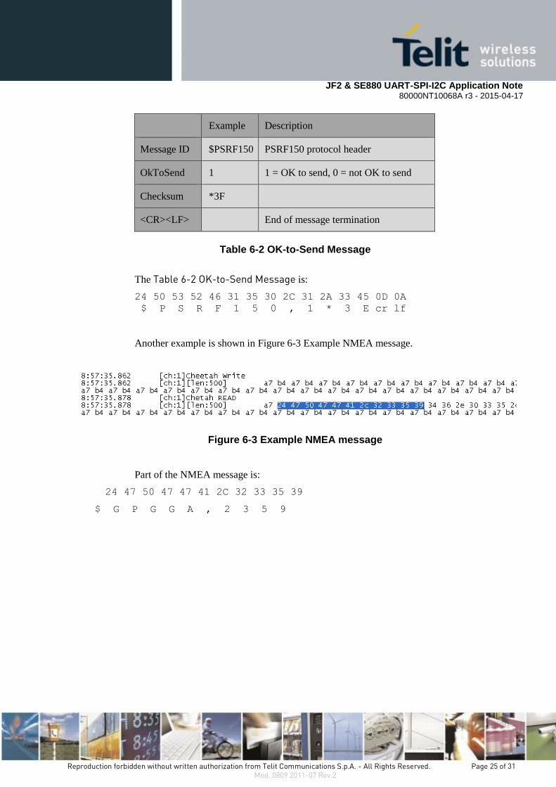
Example Description
Message ID $PSRF150 PSRF150 protocol header
OkToSend 1 1 = OK to send, 0 = not OK to send
Checksum *3F
<CR><LF> End of message termination
Table 6-2 OK-to-Send Message
The Table 6-2 OK-to-Send Message is:
24 50 53 52 46 31 35 30 2C 31 2A 33 45 0D 0A
$ P S R F 1 5 0 , 1 * 3 E cr lf
Another example is shown in Figure 6-3 Example NMEA message.
Figure 6-3 Example NMEA message
Part of the NMEA message is:
24 47 50 47 47 41 2C 32 33 35 39
$ G P G G A , 2 3 5 9

JF2 & SE880 UART-SPI-I2C Application Note
80000NT10068A r3 - 2015-04-17
Reproduction forbidden without written authorization from Telit Communications S.p.A. - All Rights Reserved. Page 26 of 31 Mod. 0809 2011-07 Rev.2
7. I2C and SPI Communications Testing
This section provides a method for independently testing the I2C and SPI communications in
designs implementing Telit’s modules. This simple process can be utilized in cases where the
system’s software may not be ready or fully functional.
Telit uses an AARDVARK SPI/I2C to USB converter, available from Total Phase
www.totalphase.com, to communicate with the module’s serial port using the SPI or I2C
protocols.
Figure 1
Example Interface Connection
Figure 7-1 AARDVARK SPI/12C to USB
Please refer to Section 3.1.1 Host Port Type Selection for information describing how to
configure the port.
When the module is started, the serial port pins will be activated as shown in Section 3.2.1
Host Port Pin Identification.
The module must correctly powered, and out of RESET before proceeding.
An ON pulse must be issued to bring the module out of hibernate mode. Allow at least 100
ms after the module is out of RESET, to issue the ON pulse. This must be a single pulse at
with least 10 ms duration.
Note: A second ON pulse will put the module back into hibernate.
The AARDVARK adapter comes with a CD which contains manuals, drivers, executables,
and source code. Please consult the AARDVARK manual for installation details.
End User Platform
Telit
Module Host
Processor
AARDVARK
SPI/I2C to USB
PC

JF2 & SE880 UART-SPI-I2C Application Note
80000NT10068A r3 - 2015-04-17
Reproduction forbidden without written authorization from Telit Communications S.p.A. - All Rights Reserved. Page 27 of 31 Mod. 0809 2011-07 Rev.2
7.1. I2C
Connect the module’s I2C DIO, and CLK to the corresponding pins on the AADVARD’s
ribbon cable.
Run the Aardvark GUI.exe program. This will open the Aardvark I2C/SPI Control Center.
Select Configure Aardvark Adapter, as shown below.
Figure 7-2 Configure Aardvark Adapter
Identify the Port where the Aardvark is connected, and select OK.
Figure 7-3 Select an Aardvark port

JF2 & SE880 UART-SPI-I2C Application Note
80000NT10068A r3 - 2015-04-17
Reproduction forbidden without written authorization from Telit Communications S.p.A. - All Rights Reserved. Page 28 of 31 Mod. 0809 2011-07 Rev.2
In the Aardvark I2C/SPI Control Center, set the Slave Addr to 0x60, and select the Master
Read button.
The master address is 0x62.
If the transaction is successful, the Data column in the Transaction Log will display the data
received from the module in hexadecimal.
Figure 7-4 Confirms successful 12C communications
This confirms successful I2C communications with the JF-2.
JF2 & SE880 UART-SPI-I2C Application Note
80000NT10068A r3 - 2015-04-17
Reproduction forbidden without written authorization from Telit Communications S.p.A. - All Rights Reserved. Page 29 of 31 Mod. 0809 2011-07 Rev.2
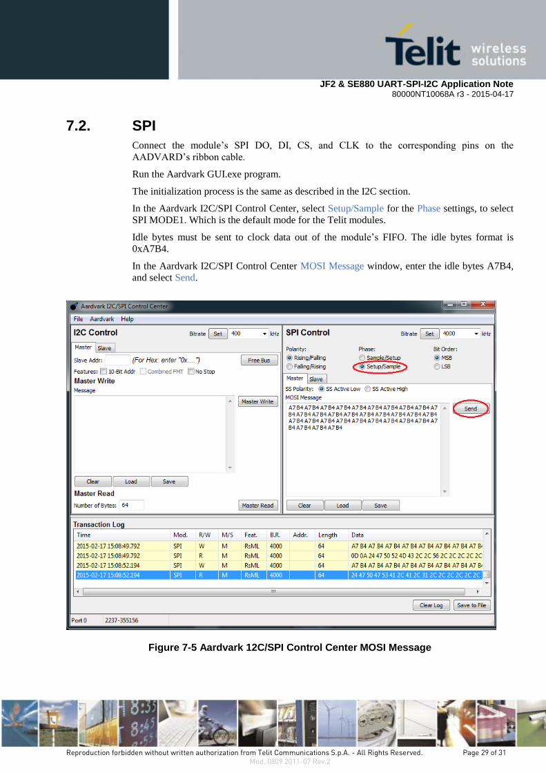
7.2. SPI
Connect the module’s SPI DO, DI, CS, and CLK to the corresponding pins on the
AADVARD’s ribbon cable.
Run the Aardvark GUI.exe program.
The initialization process is the same as described in the I2C section.
In the Aardvark I2C/SPI Control Center, select Setup/Sample for the Phase settings, to select
SPI MODE1. Which is the default mode for the Telit modules.
Idle bytes must be sent to clock data out of the module’s FIFO. The idle bytes format is
0xA7B4.
In the Aardvark I2C/SPI Control Center MOSI Message window, enter the idle bytes A7B4,
and select Send.
Figure 7-5 Aardvark 12C/SPI Control Center MOSI Message

JF2 & SE880 UART-SPI-I2C Application Note
80000NT10068A r3 - 2015-04-17
Reproduction forbidden without written authorization from Telit Communications S.p.A. - All Rights Reserved. Page 30 of 31 Mod. 0809 2011-07 Rev.2
If the transaction is successful, the Data column in the Transaction Log will display the data
received from the Telit module in hexadecimal.
This confirms successful SPI communications with the module.
JF2 & SE880 UART-SPI-I2C Application Note
80000NT10068A r3 - 2015-04-17
Reproduction forbidden without written authorization from Telit Communications S.p.A. - All Rights Reserved. Page 31 of 31 Mod. 0809 2011-07 Rev.2
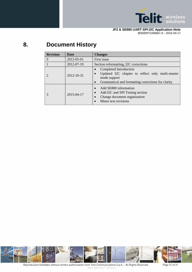
8. Document History
Revision Date Changes
0 2012-05-01 First issue
1 2012-07-19 Section reformatting, I2C corrections
2 2012-10-31
Completed Introduction
Updated I2C chapter to reflect only multi-master
mode support
Grammatical and formatting corrections for clarity
3 2015-04-17
Add SE880 information
Add I2C and SPI Testing section
Change document organization
Minor text revisions


