“dpo competency review: a statistical analysis of...
TRANSCRIPT
DYNAMIC POSITIONING CONFERENCE October 11-12 2016
COMPETENCY AND DESIGN SESSION
“DPO Competency Review: A statistical analysis of the data from the OSVDPA’s competency assessments.”
By Aaron Smith and Ben Berson
Offshore Service Vessel Dynamic Positioning Authority
Smith and Berson Competency and Design DPO Competency Review
MTS DP Conference October 11-12, 2016 Page 1
1. Abstract.
The Offshore Service Vessel Dynamic Positioning Authority (OSVDPA) presents the following paper summarizing the trends and commonalities of DPOs’ competencies, skillsets, and knowledge captured via the OSVDPA’s practical assessment system. The OSVDPA’s DPO Certification Scheme is predicated on the belief that certification is a product of classroom learning, experience gathering, and the passing of theoretical and practical assessments. The OSVDPA’s practical assessments are conducted after the third phase of training and the final phase of training. Additional assessments are required to upgrade, transfer into the OSVDPA scheme, and/or revalidate one’s DPO certificate. The OSVDPA’s practical assessment system contains of a bank of Assessment Items with each item measuring a single competency or a group of related competencies. The Assessment Items have been grouped by subject matter, applicability, and difficulty. By utilizing different combinations of items—in similar ratios—the assessments can be customized to the DPO’s industrial missions and vessels, while ensuring each assessment is of comparable content and difficulty. Additionally, each assessment item contains a unique identifier. These identifiers are also included on the assessment recordings. As such, the OSVDPA is able to track performance on an item-by-item basis. The OSVDPA intends to use the assessment data for multiple purposes (improving the OSVDPA practical assessment system, discovering deficiencies in instruction, etc.). However, sharing this aggregate and anonymous data with the broader industry is where this data can be most useful, as it exposes common faults made by those taking the assessments. By presenting this data, the OSVDPA hopes to improve the safety of our industry. Specifically, highlighting the areas in need of prioritization during DPO training and accounted for in the planning and execution of DP operations. In turn, these informed actions will lead the industry toward our shared goal of incident free operations. 2. Summary of the OSVDPA’s DPO Certification Scheme.
To understand the results presented below, one must first understand the OSVDPA DPO Certification Scheme and its foundation. The OSVDPA DPO Certification Scheme was founded on four (4) principles. Each of these principles is described below. All who use DP should be competent in the safest methods of DP utilization. The founders of the OSVDPA were repeatedly confronted with mariners operating DP systems but prevented or constrained from receiving the training that should be a prerequisite for operating a DP-equipped vessel. This situation prevented the industry from realizing its goal of incident free DP operations. As such, the OSVDPA does not believe it is the responsibility of the training scheme to decide who should be operating DP. Instead, this decision is made—regardless of the scheme owner’s beliefs—by flag states, charterers, and vessel operators. Thus, the OSVDPA will follow the lead of these entities and has set its participation requirements at levels where all that are operating DP systems can receive training and certification from the Authority, if they meet the requirements and pass the assessments.
Smith and Berson Competency and Design DPO Competency Review
MTS DP Conference October 11-12, 2016 Page 2
Training and certification requirements should be based upon a defined competency standard. The OSVDPA believes that all training and certification activities—including the assessments included within the scheme—must be based on a defined list of competencies. Such a structure ensures that vessel operators, charterers, training centers, and prospective DPOs will know what can be expected during training and what the DPO is capable of upon certification. The OSVDPA’s Technical Advisory Council (TAC) created OSVDPA CT-1-CV, the OSVDPA Competency Standard (Current Version) (see Appendix 1) by reviewing and distilling the following documents relating to DPO competency:
IMO STCW B-V/f, (International Maritime Organization, 2010); IMCA M 117, Rev. 1, (The International Marine Contractors Association, 1996); IMCA M 182, (The International Marine Contractors Association, 2009); IMCA C 002, (The International Marine Contractors Association, 2012); DNV 3.322, (Det Norske Veritas AS, 2013); DNVGL RP-0007, (DNVGL, 2014); MTS’ DP Operations Guidance, (The Marine Technology Society's Dynamic Positioning
Committee, 2012); and MTS’ MDAT, (The Marine Technology Society's Dynamic Positioning Committee, 2012)
In addition to these standards, the OSVDPA TAC layered in its own areas of emphasis. These areas represented the areas the TAC felt required increased emphasis in the training of DPOs due to the determination that these were the causes of, or had an increased likelihood of preventing, DP incidents or were areas where TAC members had observed a lacking of DPO competency. Specifically, these areas of emphasis were:
Operation planning: Ensuring that unsafe situations are not created and developing contingency and exit plans for when the conditions change or when operations cannot be continued.
Risk assessing: Ensuring the safety of an operation is preserved by conducting formal pre-operation risk assessments and constantly assessing the risk of the operation as it continues.
Communication: Increasing the safety of operations by ensuring all parties understand the status of the operation and understand their role in this operation.
Use of decision support tools: The MTS DP committee has created and popularized tools that improve the safety of operations by standardizing how vessels should be set up and when operations should or should not continue. The OSVDPA TAC found that the industry needed to do a better job of teaching DPOs and prospective DPOs how to utilize these tools.
Manual Control: When use of DP is no longer possible due to faults or failures of the DP system or changes in the enviroment, the option of last resort is to switch to manual control. As such, the TAC belives that DP training must also ensure the operator is competent in manual control of the vessel.
The OSVDPA has provided a complete review of how it created OSVDPA CT-1-CV, the OSVDPA Comptency Standard (Current Version) and how this standard relates to other international guidance at the 2014 DP Conference. This report is titled “The Evolution and Divergence of DPO Competency: Commonalities and Differences in the Competencies Required of DPOs across Industry” and is avaliable on the MTS DP Committee’s website (Smith, 2014). Please see that report for more complete information about the OSVDPA’s competency standard.

Smith and Berson Competency and Design DPO Competency Review
MTS DP Conference October 11-12, 2016 Page 3
Certification is a product of experience and assessments. The OSVDPA believes that prior to certification, prospective DPOs should have learned the basics and theory of DP in classrooms and simulators, honed these skills via participation in real world DP operations, and then prove they have become proficient with the required competencies via the passage of assessments. When put into practice, this means that the OSVDPA has a defined sea time requirement. Specifically, the scheme contains a dual layer experience requirement. In the scheme, “Sea Time” is defined as spending at least one (1) hour during a 24-hour period in the wheelhouse while the vessel is on DP, and “Practical Experience” is defined as spending between one (1) and six (6) hours in a 24-hour period at the DP console while the vessel is on DP. Through the certification scheme, prospective DPOs are required to gain 90 days of Sea Time and 270 hours of Practical Experience. When combined with the OSVDPA’s support of a defined competency standard, the OSVDPA’s experience-gathering periods all have taskbooks that must be completed, proving that the prospective DPO is gathering the experience the OSVDPA believes will make him or her a competent DPO. These tasks are designed to give the prospective DPO experience with all of the competencies included in OSVDPA CT-1-CV, the OSVDPA Competency Standard (Current Version). After the prospective DPO completes each phase of training, he or she is required to pass structured, theoretical or practical assessments. This culminates in the final assessment that must be passed before the prospective DPO is provided a DPO certificate. The OSVDPA is not alone in its support for assessment-based certification. Numerous other maritime guidance and regulation bodies have called for DPO certification schemes (as well as all training schemes) to be predicated upon or heavily upon assessments. Specifically, the following pieces of guidance and regulation call for assessments to be the deciding factors in certification or an integral part of certification:
IMCA M 117, Rev. 2, “DPO certification is obtained by successfully completing all elements of an industry recognised DPO training scheme. This includes theoretical and practical assessment and examination at appropriate stages during the scheme.” (The International Marine Contractors Association, 2016).
The United States Coast Guard 2014 Notice of Proposed Rulemaking “Requirements for MODUs and Other Vessels Conducting Outer Continental Shelf Activities with Dynamic Positioning Systems” (The United States Coast Guard , 2014)
Oil Companies International Marine Forum’s (OCIMF) “Dynamic Positioning Assurance Framework: Risk-Based Guidance states that assessments are required to maintain certification as a DPO (Oil Companies International Marine Forum, 2016).
DNVGL’s “The scheme should use summative assessments . . . to determine if a candidate can be considered competent to perform a specific task as input for the certification decision. Summative assessments or exams should determine if a person meets competence requirements as defined in the certification scheme.” (DNVGL, 2014).
The international Standards Organization (ISO) “one of the characteristic functions of the certification body for persons is to conduct an examination, which uses objective criteria to measure competence”
To ensure DPOs do not suffer from skill fade, the OSVDPA requires DPOs to revalidate their certificates every five (5) years. For the OSVDPA, revalidation also follows the principle of certification being the product of both experience and assessments. Specifically, to revalidate a certificate DPOs must show that they have accumulated 150 days of Sea Time and 450 hours of Practical Experience in the last five (5) years. Once this is proven, the DPO must again pass an assessment.

Smith and Berson Competency and Design DPO Competency Review
MTS DP Conference October 11-12, 2016 Page 4
The OSVDPA also allows for DPOs or prospective DPOs to transfer or “Grandfather” into the OSVDPA. The requirements to do so also follow the founding principle of certification being based upon experience and assessments. Specifically, to Grandfather into the scheme, a DPO or prospective DPO must prove they have met the experience-gathering requirements and pass the assessment of the phase the DPO or prospective DPO believes they have reached. Certification should be practically achievable and relevant to the industry mission(s) conducted by the DPO. The OSVDPA believes it has developed a certification scheme that will improve the safety of the dynamic positioning industry. The OSVDPA also understands individuals, unless otherwise mandated, will usually take the path of least resistance. Thus if the scheme is difficult to complete or understand it will not be utilized and the safety improvements shall not be realized. Considering this fact, the OSVDPA has attempted to remove the procedural challenges from its scheme, offering different ways for the scheme components to be completed, provided each different mechanism ensures the prospective DPO has gained the competency required by the scheme. As described in further detail below, the best example of this factor is the different ways that OSVDPA assessments can be conducted, e.g. on a simulator or on a vessel. Additionally, the OSVDPA believes as DP utilization has proliferated, the methods of how DP is utilized in the real world have also changed. This belief is predicated on the fact that multiple industry-specific appendixes have been printed to the MTS DP Committee’s DP Operations Guidance (The Marine Technology Society's Dynamic Positioning Committee, 2012) and IMCA has published IMCA M 182, International Guidelines for the Safe Operation of Dynamically Positioned Offshore Supply Vessels (The International Marine Contractors Association, 2009). Thus, while all DP training and certification programs should cover the basics of all DP operations and the theory behind DP, they should also include training tailored to higher understanding of the field or fields in which the prospective DPO is currently engaged. Such a system will ensure that DPOs are competent in the industrial missions they are currently engaged in and have the skills necessary to transition to other subsets of the industry tomorrow. To see a visual representation of how these founding principles are combined to make the OSVDPA DPO Certification Scheme, please see Appendix 2. 3. Summary of the OSVDPA Assessment System.
In addition to understanding the OSVDPA’s DPO Certification Scheme, one must also understand the OSVDPA’s Assessment System. This section provides an overview of this system. As stated above, the OSVDPA believes that its scheme—and the accompanying assessments—must be practical to complete. For this reason, OSVDPA assessments can be conducted either on a simulator, at an OSVDPA-accredited Training Provider, or on a DP-equipped vessel. When the assessment is conducted on a simulator, it is conducted by a Certified Instructor. Those certified as instructors by the OSVDPA must meet the following requirements:
They must have served as a DPO, or must have made significant contributions to the DP industry,

Smith and Berson Competency and Design DPO Competency Review
MTS DP Conference October 11-12, 2016 Page 5
Passed a course meeting the requirements of IMO Model Course 6.09, “Training Course for Instructors,” (Train the Trainer); or IMO Model Course 6.10, “Train the Simulator Trainer and Assessor”,
Passed the OSVDPA Phase 1 (theoretical) Assessment, Passed the OSVDPA Phase 3 Assessment, Passed an assessment on the OSVDPA and other DPO certification scheme requirements, and Had their ability to conduct OSVDPA assessments approved by an independent auditor contracted
by the OSVDPA. If the assessment is being conducted on a vessel, the vessel operator must be “Enrolled” in the OSVDPA. To enroll, a vessel operator must certify their employees and mariners responsible for conducting the OSVDPA assessments, making decisions about how DP is utilized onboard the vessel operator’s vessels, and transmitting information to the OSVDPA know and understand the OSVDPA assessment process and have agreed to abide by this process. Additionally, vessel operators must provide documents to the OSVDPA demonstrating how DP is utilized on their vessels and provide signatures of those that will be sending information to the OSVDPA. When the assessments are conducted in this manner, the assessments must be conducted by a mariner that has been approved by the OSVDPA as a “Qualified on Board Assessor” or “QOBA.” To be approved as a QOBA, a mariner must meet the following requirements:
Must have a valid and current DPO certificate from an industry-recognized DPO certification scheme,
Must have recorded 150 days of Sea Time and 450 hours of Practical Experience in the last five (5) years, and
Must have passed a flag-state-approved onboard assessing course. In addition to being practical, e.g. can be completed on a simulator or on a vessel, the OSVDPA believes assessments must be relevant to the industrial mission participated in by the DPO. As such, the OSVDPA assessments are primarily administered using OSVDPA-created “Scenarios.” Each scenario is designed to mimic a DP operation—often created by actual DPOs—and contained within this operation are the Assessment Items, or points of measurement, that the Certified Instructor or QOBA should score. By picking the scenario that most closely matches the operations conducted by the assessee, the Certified Instructor or QOBA ensures that the scenario is relevant to what the assessee does on a daily basis. Each scenario is contained in a printable package. The first page of the scenario provides the assessee with general information that they need to know about what they will be doing during the assessment. The rest of the package provides the points of assessment, instructions for how the assessment should be conducted, and a place to score the results. An example of the assessee and assessor portion of an Assessment Scenario is found in Appendix 3. Each of these Assessment Scenarios contains 45 points of assessment, or “Assessment Items.” 15 of these Assessment Items are known as Tier 1 Items. These are items that, if done incorrectly, would cause the vessel to lose heading or position. To pass the assessment, every Tier 1 item must be completed correctly. The other 30 Assessment Items in the scenario are Tier 2 Items. These are system monitoring, system set up, and other related aspects of DP operation. 80 percent of these items must be completed correctly for the assessment to be passed. Each of these Assessment Items is ordered how they would happen during a real DP operation and the scenario provides the assessor (either the Certified Instructor or the QOBA) with
Smith and Berson Competency and Design DPO Competency Review
MTS DP Conference October 11-12, 2016 Page 6
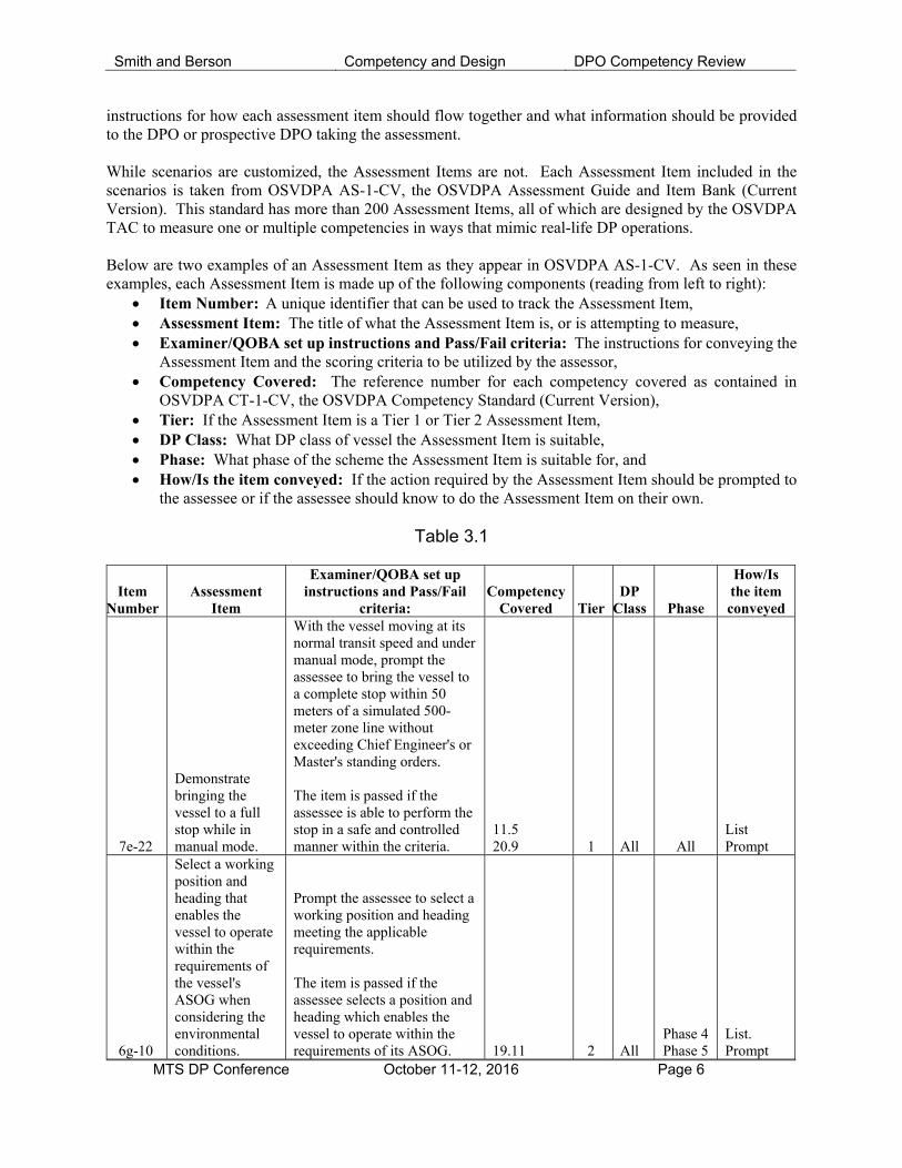
instructions for how each assessment item should flow together and what information should be provided to the DPO or prospective DPO taking the assessment. While scenarios are customized, the Assessment Items are not. Each Assessment Item included in the scenarios is taken from OSVDPA AS-1-CV, the OSVDPA Assessment Guide and Item Bank (Current Version). This standard has more than 200 Assessment Items, all of which are designed by the OSVDPA TAC to measure one or multiple competencies in ways that mimic real-life DP operations. Below are two examples of an Assessment Item as they appear in OSVDPA AS-1-CV. As seen in these examples, each Assessment Item is made up of the following components (reading from left to right):
Item Number: A unique identifier that can be used to track the Assessment Item, Assessment Item: The title of what the Assessment Item is, or is attempting to measure, Examiner/QOBA set up instructions and Pass/Fail criteria: The instructions for conveying the
Assessment Item and the scoring criteria to be utilized by the assessor, Competency Covered: The reference number for each competency covered as contained in
OSVDPA CT-1-CV, the OSVDPA Competency Standard (Current Version), Tier: If the Assessment Item is a Tier 1 or Tier 2 Assessment Item, DP Class: What DP class of vessel the Assessment Item is suitable, Phase: What phase of the scheme the Assessment Item is suitable for, and How/Is the item conveyed: If the action required by the Assessment Item should be prompted to
the assessee or if the assessee should know to do the Assessment Item on their own.
Table 3.1
Item Number
Assessment Item
Examiner/QOBA set up instructions and Pass/Fail
criteria: Competency
Covered Tier DP
Class Phase
How/Is the item conveyed
7e-22
Demonstrate bringing the vessel to a full stop while in manual mode.
With the vessel moving at its normal transit speed and under manual mode, prompt the assessee to bring the vessel to a complete stop within 50 meters of a simulated 500-meter zone line without exceeding Chief Engineer's or Master's standing orders. The item is passed if the assessee is able to perform the stop in a safe and controlled manner within the criteria.
11.5 20.9 1 All All
List Prompt
6g-10
Select a working position and heading that enables the vessel to operate within the requirements of the vessel's ASOG when considering the environmental conditions.
Prompt the assessee to select a working position and heading meeting the applicable requirements. The item is passed if the assessee selects a position and heading which enables the vessel to operate within the requirements of its ASOG. 19.11 2 All
Phase 4 Phase 5
List. Prompt
Smith and Berson Competency and Design DPO Competency Review
MTS DP Conference October 11-12, 2016 Page 7
Thus, by combining these Assessment Items in different ways, the OSVDPA can formulate Assessment Scenarios that are relevant to numerous different vessels and industrial missions and can be designed to be of similar difficulty and cover similar content. If that level of customization is still insufficient, the OSVDPA also allows scheme participants to design their own assessments, within OSVDPA prescribed parameters using two (2) means, specifically:
Designing your own scenario: Scheme participants are invited to create their own scenarios and submit these scenarios to the TAC for the TAC’s approval. Once this approval is granted, the scenario is put into the OSVDPA rotation and is able to be used by all Certified Instructors or QOBAs.
Picking your own Assessment Items: The OSVDPA also produces OSVDPA AS-2-CV, the OSVDPA Assessment Standing Order (Current Version). This periodically changing document provides a set of Assessment Items that can be utilized to create a completely customized assessment.
Regardless of where or how each assessment is conducted, the results of each assessment are captured by the OSVDPA on an Assessment Item by Assessment Item basis by the “Item Number” (see left column in the above table). The OSVDPA intends to not only utilize this data to ensure the DPO has become proficient at the required competencies but also to improve its assessment system, instruction provided at each Training Provider, the operations of vessel operators, and the industry at large. With this assessment system, the OSVDPA believes it has created an important and useful addition to DPO certification. Specifically, this assessment system stays true to the OSVDPA founding principles of being competency based, practical to implement, and relevant to the duties performed by a host of DPOs and prospective DPOs; and one that will provide benefits to the safety of the entire DP industry. 4. Content of the OSVDPA Assessment Scenario Utilized in this Analysis.
As stated above, the OSVDPA has numerous different Assessment Scenarios currently available for Certified Instructors and QOBAs to utilize. However, for the sake of easily reviewing the results, this paper presents the initial data gleaned from Scenario L-FL-1 (logistics vessel servicing a floating asset, number 1), the most used Assessment Scenario. The OSVDPA cannot provide all of the Assessment Items or instructions included in Scenario L-FL-1 as such publication would prevent the assessment from being utilized in the future, however, this section summarizes this data and compares this assessment to publicly available incident data. Additionally, a limited summary of this assessment is included in Appendix 3. In total, Scenario L-FL-1 covers 75 of the competencies listed in OSVDPA CT-1-CV, the OSVDPA Competency Standard (Current Version) on a primary basis and 156 competencies on a secondary basis (e.g. demonstrating the response to a failure of a gyro would primarily measure competency 15.8.1 and measure competency 6.4 (communication of vessel status) on a secondary basis). It is important to note, these instances include the raw number of competencies covered and have not been controlled for competencies being included multiple times. The following table displays the composition of Scenario L-FL-1 as it relates to the OSVDPA CT-1-CV, the OSVDPA Competency Standard (Current Version).
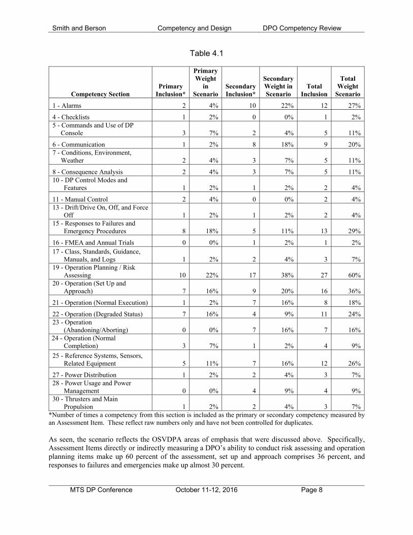
Smith and Berson Competency and Design DPO Competency Review
MTS DP Conference October 11-12, 2016 Page 8
Table 4.1
Competency Section Primary
Inclusion*
Primary Weight
in Scenario
Secondary Inclusion*
Secondary Weight in Scenario
Total Inclusion
Total Weight
Scenario
1 - Alarms 2 4% 10 22% 12 27%
4 - Checklists 1 2% 0 0% 1 2% 5 - Commands and Use of DP
Console 3 7% 2 4% 5 11%
6 - Communication 1 2% 8 18% 9 20% 7 - Conditions, Environment,
Weather 2 4% 3 7% 5 11%
8 - Consequence Analysis 2 4% 3 7% 5 11% 10 - DP Control Modes and
Features 1 2% 1 2% 2 4%
11 - Manual Control 2 4% 0 0% 2 4% 13 - Drift/Drive On, Off, and Force
Off 1 2% 1 2% 2 4% 15 - Responses to Failures and
Emergency Procedures 8 18% 5 11% 13 29%
16 - FMEA and Annual Trials 0 0% 1 2% 1 2% 17 - Class, Standards, Guidance,
Manuals, and Logs 1 2% 2 4% 3 7% 19 - Operation Planning / Risk
Assessing 10 22% 17 38% 27 60% 20 - Operation (Set Up and
Approach) 7 16% 9 20% 16 36%
21 - Operation (Normal Execution) 1 2% 7 16% 8 18%
22 - Operation (Degraded Status) 7 16% 4 9% 11 24% 23 - Operation
(Abandoning/Aborting) 0 0% 7 16% 7 16% 24 - Operation (Normal
Completion) 3 7% 1 2% 4 9%
25 - Reference Systems, Sensors, Related Equipment 5 11% 7 16% 12 26%
27 - Power Distribution 1 2% 2 4% 3 7% 28 - Power Usage and Power
Management 0 0% 4 9% 4 9% 30 - Thrusters and Main
Propulsion 1 2% 2 4% 3 7% *Number of times a competency from this section is included as the primary or secondary competency measured by an Assessment Item. These reflect raw numbers only and have not been controlled for duplicates. As seen, the scenario reflects the OSVDPA areas of emphasis that were discussed above. Specifically, Assessment Items directly or indirectly measuring a DPO’s ability to conduct risk assessing and operation planning items make up 60 percent of the assessment, set up and approach comprises 36 percent, and responses to failures and emergencies make up almost 30 percent.
Smith and Berson Competency and Design DPO Competency Review
MTS DP Conference October 11-12, 2016 Page 9
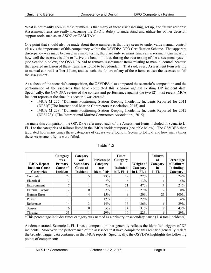
What is not readily seen in these numbers is that many of these risk assessing, set up, and failure response Assessment Items are really measuring the DPO’s ability to understand and utilize his or her decision support tools such as an ASOG or CAM/TAM. One point that should also be made about these numbers is that they seem to under value manual control vis a vis the importance of this competency within the OSVDPA DPO Certification Scheme. That apparent discrepancy was made because, in simple terms, there are only so many times an assessment can measure how well the assessee is able to “drive the boat.” In fact, during the beta testing of the assessment system (see Section 6 below) the OSVDPA had to remove Assessment Items relating to manual control because the repeated inclusion of these items was found to be redundant. That said, every Assessment Item relating to manual control is a Tier 1 Item, and as such, the failure of any of these items causes the assessee to fail the assessment. As a check of the scenario’s composition, the OSVDPA also compared the scenario’s composition and the performance of the assessees that have completed this scenario against existing DP incident data. Specifically, the OSVDPA reviewed the content and performance against the two (2) most recent IMCA incident reports at the time this scenario was created:
IMCA M 227, “Dynamic Positioning Station Keeping Incidents: Incidents Reported for 2011 (DPSI)” (The International Marine Contractors Association, 2015) and
IMCA M 228, “Dynamic Positioning Station Keeping Incidents: Incidents Reported for 2012 (DPSI 23)” (The International Marine Contractors Association , 2015).
To make this comparison, the OSVDPA referenced each of the Assessment Items included in Scenario L-FL-1 to the categories of failures listed in the IMCA incident reports (see table below). The OSVDPA then tabulated how many times these categories of causes were found in Scenario L-FL-1 and how many times these Assessment Items were failed.
Table 4.2
IMCA Report Incident Cause
Categories
Category was
Primary Cause of Incident
Category was
Secondary Cause of Incident
Percentage Category
was Identified*
Times Category
is Included in L-FL-1
Weight of Category in L-FL-1
Failures of
Category in
L-FL-1
Percentage of Failures Including Category
Computer 22 5 23% 12 27% 5 24% Electrical 7 1 7% 6 13% 1 5% Environment 7 1 7% 21 47% 5 24% External Factors 2 0 2% 12 27% 2 10% Human Error 14 4 15% 9 20% 21 100% Power 13 1 12% 10 22% 3 14% Reference 14 3 14% 16 36% 6 29% Sensor 6 0 5% 14 31% 9 43% Thruster 33 1 29% 10 22% 6 29%
*This percentage includes times category was named as a primary or secondary cause (118 total incidents). As demonstrated, Scenario L-FL-1 has a composition that generally reflects the identified triggers of DP incidents. Moreover, the performance of the assessees that have completed this scenario generally reflect the broader trigger data contained in the IMCA reports. Specifically, the OSVDPA highlights the following points of comparison:

Smith and Berson Competency and Design DPO Competency Review
MTS DP Conference October 11-12, 2016 Page 10
The DP computer triggered 23 percent of DP incidents, was reflected in 27 percent of Assessment Items, and these items accounted for 24 percent of the failed Assessment Items.
Additionally, thruster triggers represented 29 percent of the DP incidents in the relevant IMCA reports, and similarly made up 22 percent of the Assessment Items included in the scenario and 29 percent of the Assessment Item failures.
Electrical triggers made up seven (7) percent of the incidents in the above mentioned IMCA reports and made up an equally small portion of the scenario and the failed Assessment Items.
As also seen, there were differences between the IMCA incident reports and the OSVDPA assessment data. Specifically, the three biggest areas of differences were:
Human Error accounted for 15 percent of the DP incidents. However, as a competency assessment the OSVDPA said all Assessment Item failures were triggered (in part) by human error, thus this category accounted for 100 percent of the 21 failed Assessment Items. As such, this trigger category might be too different of categorization techniques to make a comparison.
The Environment trigger area accounted for only seven percent of the DP incidents submitted in 2011 and 2012 to IMCA. Yet environmental trigger factors were present in 47 percent of Assessment Items and 24 percent of the Assessment Items failed.
Finally, references and sensors accounted for a low portion of the incidents identified to IMCA but account for a large portion of the content and the Assessment Item failures
The OSVDPA feels these differences are justified. Specifically, the OSVDPA subscribes to the viewpoint articulated in the MTS DP Committee’s MDAT. This document points to the analysis of IMCA M 181, “Analysis of Station Keeping Incident Data 1994 – 2003 that is found in MTS’ MDAT. Specifically, the MDAT analysis of this data found:
32 percent of the incidents were triggered by power and propulsion issues and while these were technical issues, the consequence “loss of position” could have been avoided by appropriate operator intervention” such as proper segregation and use of decision support tools. (The Marine Technology Society's Dynamic Positioning Committee, 2012).
38 percent of the incidents were triggered by failures or issues associated with the sensors or position reference systems and the MDAT analysis found the associated loss of position could have been prevented with “appropriate operator intervention.” (The Marine Technology Society's Dynamic Positioning Committee, 2012).
21 percent of the incidents were triggered by operator error, which the MDAT analysis found could have been mitigated through the understanding and use of decision support tools, specifically an ASOG (The Marine Technology Society's Dynamic Positioning Committee, 2012).
The OSVDPA agrees with this analysis and thus has put an increased weight on operator invention and utilization of the decision support tools, noting specifically the following quote:
Systematic implementation of the guidance resulting in the development and use of the WSOG/ASOG has succeeded in reducing loss of position incidents. Investigation of the loss of position incidents where effective ASOGs were in place revealed that failure to follow the ASOG was the key and at times the sole contributing factor (The Marine Technology Society's Dynamic Positioning Committee, 2012).
Of course, these comparisons of data listed above are less than precise. The IMCA numbers reflecting the trigger of an event and the OSVDPA numbers measure the DPO’s performance of competencies involving the same general subject matter. However, the comparison is a useful benchmark confirming, in general, that the assessment is measuring the competency of DPOs in areas which have proven to cause issues or events within the industry.
Smith and Berson Competency and Design DPO Competency Review
MTS DP Conference October 11-12, 2016 Page 11
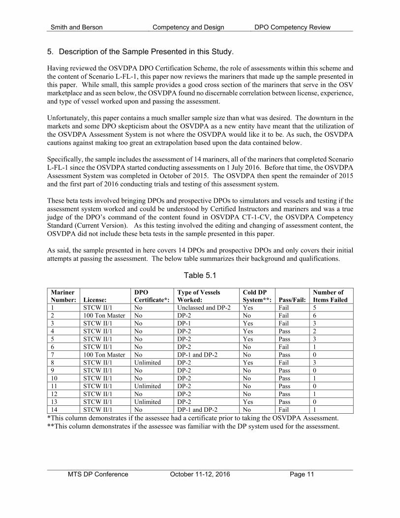
5. Description of the Sample Presented in this Study.
Having reviewed the OSVDPA DPO Certification Scheme, the role of assessments within this scheme and the content of Scenario L-FL-1, this paper now reviews the mariners that made up the sample presented in this paper. While small, this sample provides a good cross section of the mariners that serve in the OSV marketplace and as seen below, the OSVDPA found no discernable correlation between license, experience, and type of vessel worked upon and passing the assessment. Unfortunately, this paper contains a much smaller sample size than what was desired. The downturn in the markets and some DPO skepticism about the OSVDPA as a new entity have meant that the utilization of the OSVDPA Assessment System is not where the OSVDPA would like it to be. As such, the OSVDPA cautions against making too great an extrapolation based upon the data contained below. Specifically, the sample includes the assessment of 14 mariners, all of the mariners that completed Scenario L-FL-1 since the OSVDPA started conducting assessments on 1 July 2016. Before that time, the OSVDPA Assessment System was completed in October of 2015. The OSVDPA then spent the remainder of 2015 and the first part of 2016 conducting trials and testing of this assessment system. These beta tests involved bringing DPOs and prospective DPOs to simulators and vessels and testing if the assessment system worked and could be understood by Certified Instructors and mariners and was a true judge of the DPO’s command of the content found in OSVDPA CT-1-CV, the OSVDPA Competency Standard (Current Version). As this testing involved the editing and changing of assessment content, the OSVDPA did not include these beta tests in the sample presented in this paper. As said, the sample presented in here covers 14 DPOs and prospective DPOs and only covers their initial attempts at passing the assessment. The below table summarizes their background and qualifications.
Table 5.1
Mariner Number: License:
DPO Certificate*:
Type of Vessels Worked:
Cold DP System**: Pass/Fail:
Number of Items Failed
1 STCW II/1 No Unclassed and DP-2 Yes Fail 5 2 100 Ton Master No DP-2 No Fail 6 3 STCW II/1 No DP-1 Yes Fail 3 4 STCW II/1 No DP-2 Yes Pass 2 5 STCW II/1 No DP-2 Yes Pass 3 6 STCW II/1 No DP-2 No Fail 1 7 100 Ton Master No DP-1 and DP-2 No Pass 0 8 STCW II/1 Unlimited DP-2 Yes Fail 3 9 STCW II/1 No DP-2 No Pass 0 10 STCW II/1 No DP-2 No Pass 1 11 STCW II/1 Unlimited DP-2 No Pass 0 12 STCW II/1 No DP-2 No Pass 1 13 STCW II/1 Unlimited DP-2 Yes Pass 0 14 STCW II/1 No DP-1 and DP-2 No Fail 1
*This column demonstrates if the assessee had a certificate prior to taking the OSVDPA Assessment. **This column demonstrates if the assessee was familiar with the DP system used for the assessment.
Smith and Berson Competency and Design DPO Competency Review
MTS DP Conference October 11-12, 2016 Page 12
As seen, these assessees had a passing rate of only 57 percent. However, it is worth noting that all have now passed the assessment and have been certified as DPOs. The reasons for these failures are discussed more in the next section. However, as seen, the failures spanned the type of license, the type of vessel worked, and even if they were familiar or unfamiliar with the DP system utilized for the assessment. One common factor is these assessees all “Grandfathered” or transferred into the OSVDPA DPO Certification Scheme, thus they did not have the advantage—for the purposes of this assessment—of being trained in courses with a curriculum audited against the OSVDPA CT-1-CV, the OSVDPA Competency Standard (Current Version). As seen below, many of the failures dealt with a failure to utilize decision support tools such as an ASOG. As such, the OSVDPA is taking steps to ensure these assessees have the information they need to pass the assessment. 6. Results of the OSVDPA Assessments and Recommendations.
More interesting than how the assessments were conducted, the content of these assessments, or who took these assessments and their performance is a review of what items were failed. The OSVDPA presents this information to further the DP industry’s understanding of where there may be competency shortfalls. Hopefully this information can be utilized by the DP industry at large (training providers, vessel operators, simulator manufacturers, and certification schemes) to ensure these failures are not seen in real world operations or otherwise improve how the industry trains DPOs. To further this purpose, this section provides general comments on the trends seen in the failure of Assessment Items. Subsequently, this section provides detailed reviews of each Assessment Item that was failed during more than one assessment. Competency in the use of utilizing decision support tools: As previously mentioned, the OSVDPA understands that many of these failures were due to the assessee’s failure to consult or correctly utilize decision support tools (specifically the ASOG and Master’s standing orders). As such, the OSVDPA has instructed its Certified Instructors to ensure they include a review of how the ASOG should be utilized during their simulator familiarization preceding the assessment. The OSVDPA believes this instruction will help assessees that are not required to utilize an ASOG during their daily operations become more familiar with how these documents should be used and their benefit. Doing so will not only benefit the DPO—in passing the assessment—but, more importantly, will improve the safety of the industry. Manual Control: Additionally, it is worth nothing that each assessee in the small sample size utilized for this paper passed the manual control competencies. As stated above, ensuring DPOs are competent in manual control is an important part of the OSVDPA DPO Certification Scheme. Thus, this passage rate could be viewed favorably. However, the OSVDPA is concerned that these positive scores were awarded because of the limited functionality of the current manual controls included on DP simulators. This problem has arisen because prior to the OSVDPA, these controls were rarely used and were not given much importance during simulator audits. As such, these controls have an unrealistic sensitivity and little functionality. To address this situation, the OSVDPA is investigating what changes can be made to OSVDPA SIM-1-CV, the OSVDPA Simulator Standards (Current Version) to ensure Training Providers have the ability to accurately judge each assessee’s manual handling competency.
Smith and Berson Competency and Design DPO Competency Review
MTS DP Conference October 11-12, 2016 Page 13
The Buttonology of DP: As demonstrated below, few of the failures found in this data found that DPOs had a problem with the buttonology of DP, there were certainly more problems with the operational aspects, such as utilization of decision support tools. That is not to say that OSVDPA did not find failures with DPOs utilization or that training providers should decrease their instruction on how DP should be utilized. However, the OSVDPA observes that no DPO failed because their failed too many Tier 2 competencies (which are inclusive of many of the “buttonology” competencies. Familiarization Guidance: As discussed in greater detail below, the OSVDPA did find issues with DPOs switching to operations which required two (2) different PRS systems and other issues where DPOs experienced issued due to a lack of familiarity with the DP system they were being assessed on. As such, the OSVDPA urges vessel operators to pay attention to the vessel familiarization guidelines contained in Section 8 of IMCA M 117 (The International Marine Contractors Association, 2016). Significant change in data from a single gyro: In five (5) of the assessments included in the sample, the assessee failed the Assessment Item measuring the DPO’s response to the failure of one (1) gyro. When this failure occurs in the scenario, there were three (3) gyros working and enabled in the DP system. The reason for failure of the assessment item was not an inability to use the DP system. Instead, these failures were recorded for two (2) reasons: improper utilization of the ASOG and a failure to notice the incident. During these operations, the assessee was utilizing an ASOG which required the DPO to communicate to the Master, Chief Engineer, Client Representative (if on Board), and the rig any move from Green to another alert level. The ASOG clearly stated that an alarm relating to one (1) gyro or the loss of one (1) gyro would cause the vessel to move into a Blue or Advisory alert level. As such, the assessee was required to make the above-listed notifications and risk assess the situation. In four (4) of the five (5) failures, the assessee did not make this notification or risk assessment, thus the item was failed. The other failure happened because the assessee failed to notice the malfunctioning gyro. Training Providers are urged to prioritize proper understanding and utilization of ASOGs to ensure DPOs understand how to utilize this document. Additionally, Training Providers are urged to review their curriculum to ensure that proper communication, especially communication of vessel status and faults and failures, is taught. Demonstrate response to a thruster failing to full. Three (3) assessees failed to react properly to a single thruster that failed to full. While this paper is focused on the assessment cases included in the above-described data set, it is important to note this failure was seen repeatedly in the beta testing of the OSVDPA’s Assessments System. Those assessments are not included in this analysis; however, considering the critical nature of this failure, it is worth noting here. When including the beta testing cases and the relevant cases, assessees that failed this assessment item made one of two mistakes in almost equal proportions. The first group of assesees that failed this item failed it because they assumed the opposite thruster had failed to zero thrust. The other group of assessees
Smith and Berson Competency and Design DPO Competency Review
MTS DP Conference October 11-12, 2016 Page 14
failed the item because they removed the faulty thruster from the DP system but did not stop the thruster, thereby making the problem worse. While it is important for training providers and vessel operators to investigate this situation and take the corrective actions listed above, the OSVDPA is also investigating if these series of faults are due more to an issue with simulators than with competency. In after-assessment debriefs, some DPOs stated that on their vessel a thruster failing to full would have been more noticeable due to the sound and vibrations coming from the thruster. Considering this feedback, the OSVDPA is investigating changes to OSVDPA SIM-1-CV, the OSVDPA Simulator Standard (Current Version) requiring simulators to have more realistic audio features, thereby providing the assessee a more true-to-life assessment. Conversely, some DPOs, especially those serving on larger vessels, have correctly stated that as vessels get bigger, more complex, and with more creature comforts such as better sound insulation, they provide DPOs less ability to benefit from tactile or audio inputs. As such, this group of DPOs recommended no changes be made to the audio provided by the simulator; thereby, forcing the assessee to focus upon the information provided by the DP console, specifically, the thruster set point and feedback. Setting up the vessel in accordance with its intended IMO equipment class: In three (3) assessments, the assessee failed to set up the vessels in accordance with the requirements of the IMO intended equipment class. In both cases, the reason for the failure was the assessee did not enable the vessel’s consequence analysis feature. This is a feature required to be enabled by Section 3.4.2 of IMO MSC/Circ. 645, “Guidelines or Vessels with Dynamic Positioning Systems” (International Maritime Organization, 1994). The OSVDPA recommends that vessel operators ensure that a line item requiring the DPO to verify the consequence analysis is enabled is part of the 500-meter checklists for every DP-2 or DP-3 vessel. Additionally, as the IMO is currently updating IMO MSC/Circ. 645, the OSVDPA recommends that all vessel operators and training providers follow this updating and ensure their employees are aware of when the new version of IMO MSC/Circ. 645 is released and its requirements. Setting up, validating, and enabling the required number of laser-based reference systems: In two (2) cases the assessee failed the Assessment Item requiring them to set up and enable the laser-based position reference system into the DP system. In these cases, the assessee only utilized absolute reference systems (DGPS). In making this failure, the assessees violated the vessel’s CAM, ASOG, Master Standing Orders, and prevented the vessel from operating at its intended IMO equipment class (3.4.3 of IMO MSC/Circ. 645 (International Maritime Organization, 1994)). Considering this fact, vessel operators should take care to ensure that their checklists, CAMs, ASOGs and other similar documents instruct DPOs to ensure at least two (2) different types of reference systems are enabled. Setting the gain settings in accordance with the ASOG or decision support tool: In the scenario utilized for the assessments that make up this sample, an Assessment Item is included which requires the assessee to set the gain settings in accordance with the vessel’s ASOG or decision support tool. In two (2) cases, this item was failed because the assessee failed to review what the gain settings were set
Smith and Berson Competency and Design DPO Competency Review
MTS DP Conference October 11-12, 2016 Page 15
at or to review these settings or the effect of these settings against any of the decision support tools carried aboard the vessel. As a corrective action, the OSVDPA urges training providers to explain why pre-operation checklists are utilized and their importance. 7. Conclusions.
As demonstrated, the OSVDPA has created an assessment system which is based upon industry best practices and provides a practical means to test a DPO or prospective DPO’s competency in ways that are relevant to the industry mission conducted by that mariner. From the initial—admittedly limited—data, the composition of this assessment reflects the triggers of real world DP incidents. As such, the assessment is not only a good judge of the competency of DPOs, but the results are also a good indicator of where threats to safety may lay. Our initial data indicates that understanding and utilization of decision support tools continues to be an issue that needs to be addressed in our industry. Additionally, our data indicates that an understanding of how the DP system is utilized may be of concern. From the information that has been gleaned to date (both the case study of the assessment sample included in this paper and the beta testing of the assessment that was done prior) and the responses from the DPOs that have taken our assessments, the OSVDPA feels the difficulty and subject matter of our assessments is appropriate for the industry. Bibliography.
Det Norske Veritas AS. 2013. Competence of Dynamic Positioning Operators (DPO). Oslo : Det Norske Veritas, 2013. 3.322. DNVGL. 2014. Certiication Scheme for Dynamic Positioning Operators. Oslo : DNVGL, 2014. DNVGL-RP-0007. International Maritime Organization. 1994. Guidelines for Vessels with Dynamic Positioning Systems. London : International Maritime Organization, 1994. MSC/Circ. 645. —. 2010. The International Conventions on Standards of Training, Certification, and Watchkeeping for Seafarers. London : The International Maritime Organization, 2010. 2010. Oil Companies International Marine Forum. 2016. Dynamic Positioning Assurance Framework: Risk-Based Guidance. London : Oil Companies International Marine Forum, 2016. Smith, Aaron. 2014. The Evolution and Divergence of DPO Competency: Commonalities and Differences in the Competencies Required of DPOs across Industry. Houston : Marine Technology Society, Dynamic Positioning Committee, 2014. The International Marine Contractors Association . 2015. Dynamic Positioning Station Keeping Incidents: Incidents Reported for 2012 (DPSI 23). London : The International Marine Contractors Association, 2015. IMCA M 228.
Smith and Berson Competency and Design DPO Competency Review
MTS DP Conference October 11-12, 2016 Page 16
The International Marine Contractors Association. 2015. Dynamic Positioning Station Keeping Incidents: Incident Reported for 2011 (DPSI 22). London : The International Marine Contractors Association , 2015. IMCA M 227. —. 2012. Guidance on Competence Assurance and Assessment. London : The International Marine Contractors Association, 2012. IMCA C 002 Rev. 2. —. 2016. Guidelines for the Training and Experience of Key DP Personnel. London : The International Marine Contractors Association, 2016. IMCA M 117 Rev. 2. —. 2009. International Guidelines for the Safe Operation of Dynamically Positioned Offshore Supply Vessels. London : The International Marine Contractors Association, 2009. IMCA M 182. —. 1996. The Training and Experience of Key DP Personnel. London : The International Marine Contractors Association , 1996. IMCA M 117, Rev. 1. The Marine Technology Society's Dynamic Positioning Committee. 2012. DP Operation Guidance . Houston : The Marine Technology Society's Dynamic Positioning Committee , 2012. —. 2012. Guidance for Professional Development of Personnel Engaged in DP Operations using the Mapping Delivery Tool (MDAT). Houston : The Marine Technology Society , 2012. The United States Coast Guard . 2014. Requirements for MODUs and Other Vessels Conducting Outer Continental Shelf Activities with Dynamic Positioning Systems. Washington DC : United States Government Printing Office, 2014. Federal Register Vol. 79, No. 229, Docket USCG-2014-0063.
Smith and Berson Competency and Design DPO Competency Review
MTS DP Conference October 11-12, 2016 Page 17
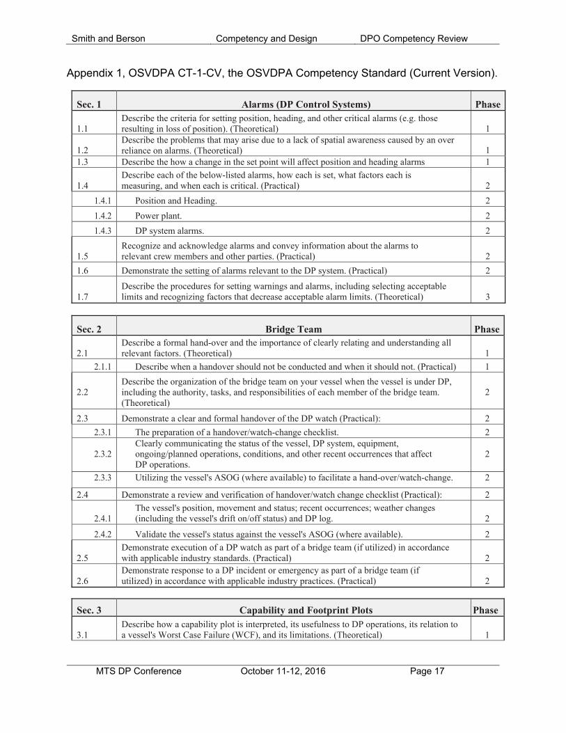
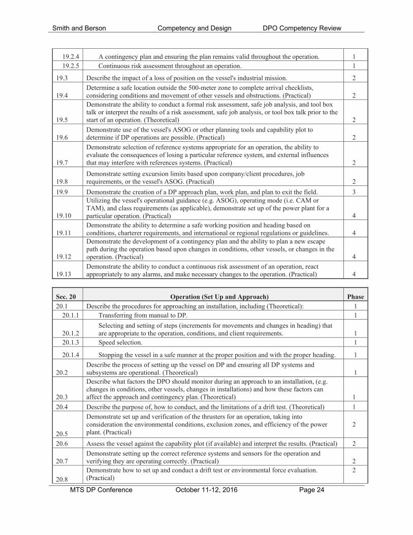
Appendix 1, OSVDPA CT-1-CV, the OSVDPA Competency Standard (Current Version).
Sec. 1 Alarms (DP Control Systems) Phase 1.1
Describe the criteria for setting position, heading, and other critical alarms (e.g. those resulting in loss of position). (Theoretical)
1
1.2
Describe the problems that may arise due to a lack of spatial awareness caused by an over reliance on alarms. (Theoretical)
1
1.3 Describe the how a change in the set point will affect position and heading alarms 1
1.4
Describe each of the below-listed alarms, how each is set, what factors each is measuring, and when each is critical. (Practical)
2
1.4.1 Position and Heading. 2
1.4.2 Power plant. 2
1.4.3 DP system alarms. 2
1.5
Recognize and acknowledge alarms and convey information about the alarms to relevant crew members and other parties. (Practical)
2
1.6 Demonstrate the setting of alarms relevant to the DP system. (Practical) 2
1.7
Describe the procedures for setting warnings and alarms, including selecting acceptable limits and recognizing factors that decrease acceptable alarm limits. (Theoretical)
3
Sec. 2 Bridge Team Phase 2.1
Describe a formal hand-over and the importance of clearly relating and understanding all relevant factors. (Theoretical)
1
2.1.1 Describe when a handover should not be conducted and when it should not. (Practical) 1
2.2
Describe the organization of the bridge team on your vessel when the vessel is under DP, including the authority, tasks, and responsibilities of each member of the bridge team. (Theoretical)
2
2.3 Demonstrate a clear and formal handover of the DP watch (Practical): 2
2.3.1 The preparation of a handover/watch-change checklist. 2
2.3.2 Clearly communicating the status of the vessel, DP system, equipment, ongoing/planned operations, conditions, and other recent occurrences that affect DP operations.
2
2.3.3 Utilizing the vessel's ASOG (where available) to facilitate a hand-over/watch-change. 2
2.4 Demonstrate a review and verification of handover/watch change checklist (Practical): 2
2.4.1
The vessel's position, movement and status; recent occurrences; weather changes (including the vessel's drift on/off status) and DP log.
2
2.4.2 Validate the vessel's status against the vessel's ASOG (where available). 2
2.5
Demonstrate execution of a DP watch as part of a bridge team (if utilized) in accordance with applicable industry standards. (Practical)
2
2.6
Demonstrate response to a DP incident or emergency as part of a bridge team (if utilized) in accordance with applicable industry practices. (Practical)
2
Sec. 3 Capability and Footprint Plots Phase 3.1
Describe how a capability plot is interpreted, its usefulness to DP operations, its relation to a vessel's Worst Case Failure (WCF), and its limitations. (Theoretical)
1
Smith and Berson Competency and Design DPO Competency Review
MTS DP Conference October 11-12, 2016 Page 18
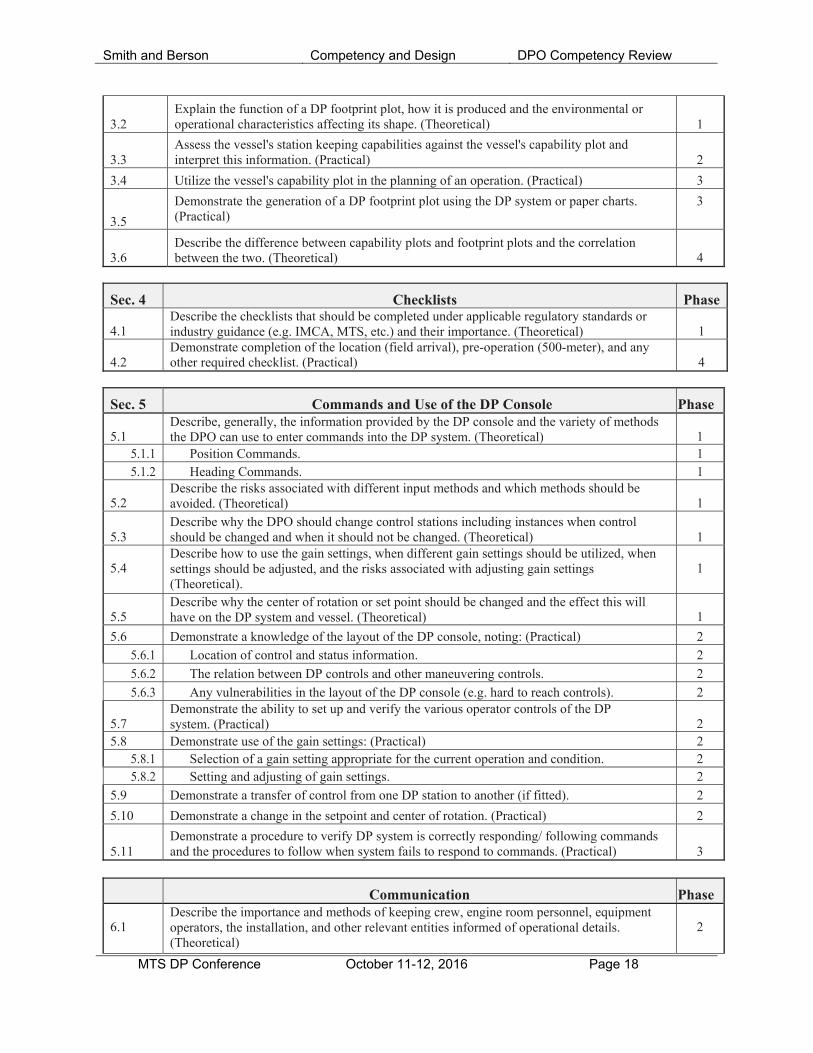
3.2
Explain the function of a DP footprint plot, how it is produced and the environmental or operational characteristics affecting its shape. (Theoretical)
1
3.3
Assess the vessel's station keeping capabilities against the vessel's capability plot and interpret this information. (Practical)
2
3.4 Utilize the vessel's capability plot in the planning of an operation. (Practical) 3
3.5
Demonstrate the generation of a DP footprint plot using the DP system or paper charts. (Practical)
3
3.6
Describe the difference between capability plots and footprint plots and the correlation between the two. (Theoretical)
4
Sec. 4 Checklists Phase 4.1
Describe the checklists that should be completed under applicable regulatory standards or industry guidance (e.g. IMCA, MTS, etc.) and their importance. (Theoretical)
1
4.2
Demonstrate completion of the location (field arrival), pre-operation (500-meter), and any other required checklist. (Practical)
4
Sec. 5 Commands and Use of the DP Console Phase 5.1
Describe, generally, the information provided by the DP console and the variety of methods the DPO can use to enter commands into the DP system. (Theoretical)
1
5.1.1 Position Commands. 1 5.1.2 Heading Commands. 1
5.2
Describe the risks associated with different input methods and which methods should be avoided. (Theoretical)
1
5.3
Describe why the DPO should change control stations including instances when control should be changed and when it should not be changed. (Theoretical)
1
5.4
Describe how to use the gain settings, when different gain settings should be utilized, when settings should be adjusted, and the risks associated with adjusting gain settings (Theoretical).
1
5.5
Describe why the center of rotation or set point should be changed and the effect this will have on the DP system and vessel. (Theoretical)
1
5.6 Demonstrate a knowledge of the layout of the DP console, noting: (Practical) 2 5.6.1 Location of control and status information. 2
5.6.2 The relation between DP controls and other maneuvering controls. 2
5.6.3 Any vulnerabilities in the layout of the DP console (e.g. hard to reach controls). 2 5.7
Demonstrate the ability to set up and verify the various operator controls of the DP system. (Practical)
2
5.8 Demonstrate use of the gain settings: (Practical) 2 5.8.1 Selection of a gain setting appropriate for the current operation and condition. 2 5.8.2 Setting and adjusting of gain settings. 2
5.9 Demonstrate a transfer of control from one DP station to another (if fitted). 2
5.10 Demonstrate a change in the setpoint and center of rotation. (Practical) 2
5.11
Demonstrate a procedure to verify DP system is correctly responding/ following commands and the procedures to follow when system fails to respond to commands. (Practical)
3
Communication Phase 6.1
Describe the importance and methods of keeping crew, engine room personnel, equipment operators, the installation, and other relevant entities informed of operational details. (Theoretical)
2
Smith and Berson Competency and Design DPO Competency Review
MTS DP Conference October 11-12, 2016 Page 19
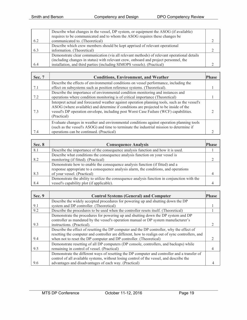
6.2
Describe what changes in the vessel, DP system, or equipment the ASOG (if available) requires to be communicated and to whom the ASOG requires these changes be communicated to. (Theoretical)
2 6.3
Describe which crew members should be kept apprised of relevant operational information. (Theoretical)
2
6.4
Demonstrate clear communication (via all relevant methods) of relevant operational details (including changes in status) with relevant crew, onboard and project personnel, the installation, and third parties (including SIMOPS vessels). (Practical)
2
Sec. 7 Conditions, Environment, and Weather Phase 7.1
Describe the effects of environmental conditions on vessel performance, including the effect on subsystems such as position reference systems. (Theoretical).
1
7.2
Describe the importance of environmental condition monitoring and instances and operations where condition monitoring is of critical importance (Theoretical)
1
7.3
Interpret actual and forecasted weather against operation planning tools, such as the vessel's ASOG (where available) and determine if conditions are projected to be inside of the vessel's DP operation envelope, including post Worst Case Failure (WCF) capabilities. (Practical)
2
7.4
Evaluate changes in weather and environmental conditions against operation planning tools (such as the vessel's ASOG) and time to terminate the industrial mission to determine if operations can be continued. (Practical)
2
Sec. 8 Consequence Analysis Phase 8.1 Describe the importance of the consequence analysis function and how it is used. 1
8.2
Describe what conditions the consequence analysis function on your vessel is monitoring (if fitted). (Practical)
2
8.3
Demonstrate how to enable the consequence analysis function (if fitted) and a response appropriate to a consequence analysis alarm, the conditions, and operations of your vessel. (Practical)
4 8.4
Demonstrate the ability to utilize the consequence analysis function in conjunction with the vessel's capability plot (if applicable).
4
Sec. 9 Control Systems (General) and Computer Phase 9.1
Describe the widely accepted procedures for powering up and shutting down the DP system and DP controller. (Theoretical)
1
9.2 Describe the procedures to be used when the controller resets itself. (Theoretical) 1 9.3
Demonstrate the procedures for powering up and shutting down the DP system and DP controller as mandated by the vessel's operation manual or DP system manufacturer’s instructions. (Practical).
2 9.4
Describe the effect of resetting the DP computer and the DP controller, why the effect of resetting the computer and controller are different, how to realign out of sync controllers, and when not to reset the DP computer and DP controller. (Theoretical)
2 9.5
Demonstrate resetting of all DP computers (DP console, controllers, and backups) while remaining in control of vessel. (Practical)
4
9.6
Demonstrate the different ways of resetting the DP computer and controller and a transfer of control of all available systems, without losing control of the vessel, and describe the advantages and disadvantages of each way. (Practical)
4
Smith and Berson Competency and Design DPO Competency Review
MTS DP Conference October 11-12, 2016 Page 20
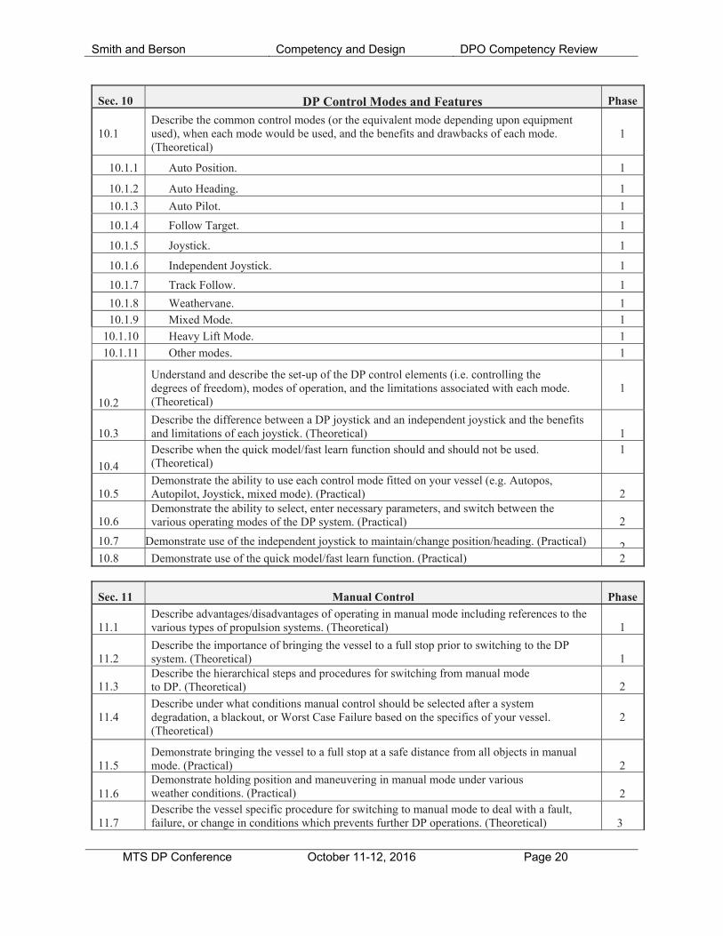
Sec. 10 DP Control Modes and Features Phase
10.1
Describe the common control modes (or the equivalent mode depending upon equipment used), when each mode would be used, and the benefits and drawbacks of each mode. (Theoretical)
1
10.1.1 Auto Position. 1
10.1.2 Auto Heading. 1
10.1.3 Auto Pilot. 1
10.1.4 Follow Target. 1
10.1.5 Joystick. 1
10.1.6 Independent Joystick. 1
10.1.7 Track Follow. 1
10.1.8 Weathervane. 1
10.1.9 Mixed Mode. 1
10.1.10 Heavy Lift Mode. 1
10.1.11 Other modes. 1
10.2
Understand and describe the set-up of the DP control elements (i.e. controlling the degrees of freedom), modes of operation, and the limitations associated with each mode. (Theoretical)
1
10.3
Describe the difference between a DP joystick and an independent joystick and the benefits and limitations of each joystick. (Theoretical)
1
10.4
Describe when the quick model/fast learn function should and should not be used. (Theoretical)
1
10.5
Demonstrate the ability to use each control mode fitted on your vessel (e.g. Autopos, Autopilot, Joystick, mixed mode). (Practical)
2
10.6
Demonstrate the ability to select, enter necessary parameters, and switch between the various operating modes of the DP system. (Practical)
2
10.7 Demonstrate use of the independent joystick to maintain/change position/heading. (Practical) 210.8 Demonstrate use of the quick model/fast learn function. (Practical) 2
Sec. 11 Manual Control Phase
11.1
Describe advantages/disadvantages of operating in manual mode including references to the various types of propulsion systems. (Theoretical)
1
11.2
Describe the importance of bringing the vessel to a full stop prior to switching to the DP system. (Theoretical)
1
11.3
Describe the hierarchical steps and procedures for switching from manual mode to DP. (Theoretical)
2
11.4
Describe under what conditions manual control should be selected after a system degradation, a blackout, or Worst Case Failure based on the specifics of your vessel. (Theoretical)
2
11.5
Demonstrate bringing the vessel to a full stop at a safe distance from all objects in manual mode. (Practical)
2
11.6
Demonstrate holding position and maneuvering in manual mode under various weather conditions. (Practical)
2
11.7
Describe the vessel specific procedure for switching to manual mode to deal with a fault, failure, or change in conditions which prevents further DP operations. (Theoretical)
3
Smith and Berson Competency and Design DPO Competency Review
MTS DP Conference October 11-12, 2016 Page 21
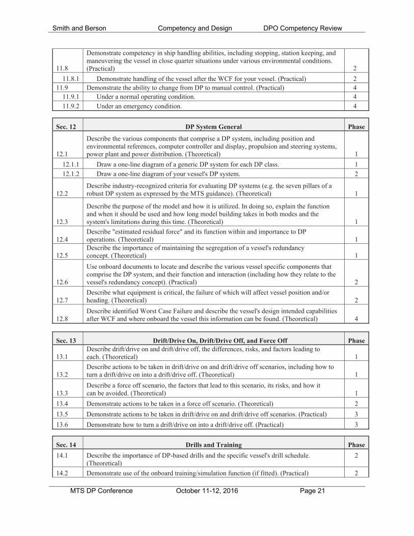
11.8
Demonstrate competency in ship handling abilities, including stopping, station keeping, and maneuvering the vessel in close quarter situations under various environmental conditions. (Practical)
2
11.8.1 Demonstrate handling of the vessel after the WCF for your vessel. (Practical) 2 11.9 Demonstrate the ability to change from DP to manual control. (Practical) 4
11.9.1 Under a normal operating condition. 4
11.9.2 Under an emergency condition. 4
Sec. 12 DP System General Phase
12.1
Describe the various components that comprise a DP system, including position and environmental references, computer controller and display, propulsion and steering systems, power plant and power distribution. (Theoretical)
1
12.1.1 Draw a one-line diagram of a generic DP system for each DP class. 1
12.1.2 Draw a one-line diagram of your vessel's DP system. 2
12.2
Describe industry-recognized criteria for evaluating DP systems (e.g. the seven pillars of a robust DP system as expressed by the MTS guidance). (Theoretical)
1
12.3
Describe the purpose of the model and how it is utilized. In doing so, explain the function and when it should be used and how long model building takes in both modes and the system's limitations during this time. (Theoretical)
1
12.4
Describe "estimated residual force" and its function within and importance to DP operations. (Theoretical)
1
12.5
Describe the importance of maintaining the segregation of a vessel's redundancy concept. (Theoretical)
1
12.6
Use onboard documents to locate and describe the various vessel specific components that comprise the DP system, and their function and interaction (including how they relate to the vessel's redundancy concept). (Practical)
2
12.7
Describe what equipment is critical, the failure of which will affect vessel position and/or heading. (Theoretical)
2
12.8
Describe identified Worst Case Failure and describe the vessel's design intended capabilities after WCF and where onboard the vessel this information can be found. (Theoretical)
4
Sec. 13 Drift/Drive On, Drift/Drive Off, and Force Off Phase 13.1
Describe drift/drive on and drift/drive off, the differences, risks, and factors leading to each. (Theoretical)
1
13.2
Describe actions to be taken in drift/drive on and drift/drive off scenarios, including how to turn a drift/drive on into a drift/drive off. (Theoretical)
1
13.3
Describe a force off scenario, the factors that lead to this scenario, its risks, and how it can be avoided. (Theoretical)
1
13.4 Demonstrate actions to be taken in a force off scenario. (Theoretical) 2
13.5 Demonstrate actions to be taken in drift/drive on and drift/drive off scenarios. (Practical) 3
13.6 Demonstrate how to turn a drift/drive on into a drift/drive off. (Practical) 3
Sec. 14 Drills and Training Phase
14.1 Describe the importance of DP-based drills and the specific vessel's drill schedule. (Theoretical)
2
14.2 Demonstrate use of the onboard training/simulation function (if fitted). (Practical) 2
Smith and Berson Competency and Design DPO Competency Review
MTS DP Conference October 11-12, 2016 Page 22
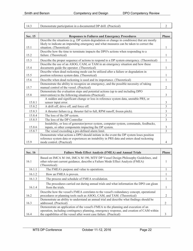
14.3 Demonstrate participation in a documented DP drill. (Practical) 2
Sec. 15 Responses to Failures and Emergency Procedures Phase 15.1
Describe the situations (e.g. DP system degradation or change in conditions) that are mostly likely to indicate an impending emergency and what measures can be taken to correct the situation. (Theoretical)
1 15.2
Describe how the time to terminate impacts the DPO's actions when responding to a failure. (Theoretical)
1
15.3 Describe the proper sequence of actions to respond to a DP system emergency. (Theoretical) 1 15.4
Describe the use of an ASOG, CAM, or TAM in an emergency situation and how these documents guide the operator. (Theoretical)
1
15.5
Describe when dead reckoning mode can be utilized after a failure or degradation in position reference system data. (Theoretical)
1
15.6 Describe when dead reckoning is used and its importance. (Theoretical) 1 15.7
Demonstrate the ability to recognize an emergency, and the possible necessity of taking manual control of the vessel. (Practical)
2
15.8
Demonstrate the evaluation steps and potential actions (up to and including DPO intervention) to the following situations (Practical):
3
15.8.1
A sudden and significant change or loss in reference system data, unstable PRS, or sensor input error.
3
15.8.2 A drift off, drive off, and force off. 3
15.8.3 A thruster failure (e.g. thruster fail to full, RPM runoff, frozen pitch). 3 15.8.4 The loss of the DP system. 3 15.8.5 The loss of the DP Controller 3
15.8.6
Instability, or loss of generator/power system, computer system, commands, feedbacks, inputs, or other components impacting the DP system.
3
15.8.7 The vessel exceeding a pre-defined alarm limit. 3 15.9
Demonstrate what actions a DPO should initiate in the event the DP system loses position reference system data or experiences an instability in PRS data and enters dead reckoning mode control. (Practical)
4
Sec. 16 Failure Mode Effect Analysis (FMEA) and Annual Trials Phase
16.1
Based on IMCA M 166, IMCA M 190, MTS' DP Vessel Design Philosophy Guidelines, and other relevant current guidance, describe a Failure Mode Effect Analysis (FMEA) (Theoretical):
1
16.1.1 The FMEA's purpose and value to operations. 1
16.1.2 How an FMEA is proven. 1
16.1.3 The process and schedule of FMEA revalidation. 1
16.1.4
The procedures carried out during annual trials and what information the DPO can glean from the trials.
1
16.2
Describe how the vessel's FMEA correlates to the vessel's redundancy concept, operational procedures or planning tools such as ASOG, CAM, and TAM. (Theoretical)
2
16.3
Demonstrate an ability to understand an annual trial and describe what findings should be addressed. (Practical)
2
16.4
Demonstrate an application of the vessel's FMEA to the planning and execution of an operation, including contingency planning, emergency response, and creation of CAM within the capabilities of the vessel after worst case failure. (Practical)
3
Smith and Berson Competency and Design DPO Competency Review
MTS DP Conference October 11-12, 2016 Page 23
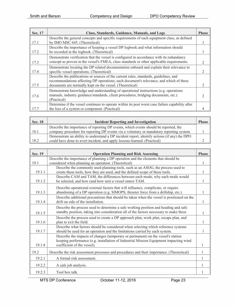
Sec. 17 Class, Standards, Guidance, Manuals, and Logs Phase 17.1
Describe the general concepts and specific requirements of each equipment class, as defined by IMO MSC 645. (Theoretical)
1
17.2
Describe the importance of keeping a vessel DP logbook and what information should be recorded in the logbook. (Theoretical)
1
17.3
Demonstrate verification that the vessel is configured in accordance with its redundancy concept as proven in the vessel's FMEA, class standards or other applicable requirements. ( i l)
2
17.4
Demonstrate locating the DP related documentation onboard and explain their relevance to specific vessel operations. (Theoretical)
2
17.5
Describe the publications or sources of the current rules, standards, guidelines, and recommendations affecting DP operations; each document's relevance, and which of these documents are normally kept on the vessel. (Theoretical)
2
17.6
Demonstrate knowledge and understanding of operational instructions (e.g. operations manuals, industry guidance/standards, client procedures, bridging documents, etc.). (Practical)
2
17.7
Determine if the vessel continues to operate within its post worst case failure capability after the loss of a system or component. (Practical)
4
Sec. 18 Incident Reporting and Investigation Phase 18.1
Describe the importance of reporting DP events, which events should be reported, the company procedure for reporting DP events via a voluntary or mandatory reporting system.
1
18.2
Demonstrate an ability to understand a DP incident report, identify actions (if any) the DPO could have done to avert incident, and apply lessons-learned. (Practical)
2
Sec. 19 Operation Planning and Risk Assessing Phase 19.1
Describe the importance of planning a DP operation and the elements that should be considered when planning an operation. (Theoretical)
1
19.1.1
Describe the commonly used planning tools, such as an ASOG, the process used to create these tools, how they are used, and the defined scope of these tools.
1
19.1.2
Describe CAM and TAM, the differences between each mode, why each mode would be selected, and how (and how not) a vessel enters TAM.
1
19.1.3
Describe operational external factors that will influence, complicate, or require abandoning of a DP operation (e.g. SIMOPS, thruster force from a drillship, etc.).
1
19.1.4
Describe additional precautions that should be taken when the vessel is positioned on the drift on side of the installation.
1
19.1.5
Describe the process used to determine a safe working position and heading and safe standby position, taking into consideration all of the factors necessary to make these d i i
1
19.1.6
Describe the process used to create a DP approach plan, work plan, escape plan, and plan to exit the field.
1
19.1.7
Describe what factors should be considered when selecting which reference systems should be used for an operation and the limitations carried by each system.
1
19.1.8
Describe the impacts of changes (temporary or permanent) on the vessel's station keeping performance (e.g. installation of Industrial Mission Equipment impacting wind coefficient of the vessel).
1
19.2 Describe the risk assessment processes and procedures and their importance. (Theoretical) 1
19.2.1 A formal risk assessment. 1
19.2.2 A safe job analysis. 1
19.2.3 Tool box talk. 1
Smith and Berson Competency and Design DPO Competency Review
MTS DP Conference October 11-12, 2016 Page 24
19.2.4 A contingency plan and ensuring the plan remains valid throughout the operation. 1 19.2.5 Continuous risk assessment throughout an operation. 1
19.3 Describe the impact of a loss of position on the vessel's industrial mission. 2
19.4
Determine a safe location outside the 500-meter zone to complete arrival checklists, considering conditions and movement of other vessels and obstructions. (Practical)
2
19.5
Demonstrate the ability to conduct a formal risk assessment, safe job analysis, and tool box talk or interpret the results of a risk assessment, safe job analysis, or tool box talk prior to the start of an operation. (Theoretical)
2
19.6
Demonstrate use of the vessel's ASOG or other planning tools and capability plot to determine if DP operations are possible. (Practical)
2
19.7
Demonstrate selection of reference systems appropriate for an operation, the ability to evaluate the consequences of losing a particular reference system, and external influences that may interfere with references systems. (Practical)
2
19.8
Demonstrate setting excursion limits based upon company/client procedures, job requirements, or the vessel's ASOG. (Practical)
2
19.9 Demonstrate the creation of a DP approach plan, work plan, and plan to exit the field. 3 19.10
Utilizing the vessel's operational guidance (e.g. ASOG), operating mode (i.e. CAM or TAM), and class requirements (as applicable), demonstrate set up of the power plant for a particular operation. (Practical)
4
19.11
Demonstrate the ability to determine a safe working position and heading based on conditions, charterer requirements, and international or regional regulations or guidelines.
4
19.12
Demonstrate the development of a contingency plan and the ability to plan a new escape path during the operation based upon changes in conditions, other vessels, or changes in the operation. (Practical)
4
19.13
Demonstrate the ability to conduct a continuous risk assessment of an operation, react appropriately to any alarms, and make necessary changes to the operation. (Practical)
4
Sec. 20 Operation (Set Up and Approach) Phase
20.1 Describe the procedures for approaching an installation, including (Theoretical): 1 20.1.1 Transferring from manual to DP. 1
20.1.2
Selecting and setting of steps (increments for movements and changes in heading) that are appropriate to the operation, conditions, and client requirements.
1
20.1.3 Speed selection. 1
20.1.4 Stopping the vessel in a safe manner at the proper position and with the proper heading. 1
20.2
Describe the process of setting up the vessel on DP and ensuring all DP systems and subsystems are operational. (Theoretical)
1
20.3
Describe what factors the DPO should monitor during an approach to an installation, (e.g. changes in conditions, other vessels, changes in installations) and how these factors can affect the approach and contingency plan. (Theoretical)
1
20.4 Describe the purpose of, how to conduct, and the limitations of a drift test. (Theoretical) 1
20.5
Demonstrate set up and verification of the thrusters for an operation, taking into consideration the environmental conditions, exclusion zones, and efficiency of the power plant. (Practical)
2
20.6 Assess the vessel against the capability plot (if available) and interpret the results. (Practical) 2
20.7
Demonstrate setting up the correct reference systems and sensors for the operation and verifying they are operating correctly. (Practical)
2
20.8 Demonstrate how to set up and conduct a drift test or environmental force evaluation. (Practical)
2

Smith and Berson Competency and Design DPO Competency Review
MTS DP Conference October 11-12, 2016 Page 25
20.9
Utilizing company/client requirements and/or the vessel's operational guidance (e.g. ASOG), demonstrate stopping and stabilizing the vessel in a controlled manner and safe position; switching from manual control, to joystick, to full DP; then beginning the approach to the worksite. (Practical)
2 20.10
Utilizing company procedures, client requirements, and/or the vessel's operational guidance (e.g. ASOG), demonstrate proper selection of speed and steps to approach an installation. (Practical)
2
20.11
Demonstrate anticipation and reactions appropriate and proportional to changes in operational or environmental conditions during the approach. (Practical)
2
Sec. 21 Operation (Normal Phase
21.1 Describe the items a DPO should be monitoring during a DP operation. (Theoretical) 1 21.2
Describe center of rotation, how the DPO selects the center of rotation and set point, its effect on the DP system and controls and why selecting a center of rotation appropriate to the conditions and operation is important. (Theoretical)
1 21.3
Describe factors, (e.g. deployed equipment), that may limit a vessel's performance or ability. (Theoretical)
1
21.4
Describe how changes in the installation’s heading and position can affect an DP operation. (Theoretical)
1
21.5
Describe the need to anticipate changes in the operation and make changes when necessary. (Theoretical)
1
21.6 Describe the process of selecting an additional PRS. (Theoretical) 1
21.7 Describe how to use an ASOG to determine if continued operations are possible. (Theoretical)
1
21.8
Describe the potential causal factors for an inexplicable ramp up of thrusters and the means employed by the DPO to discriminate faulty inputs. (Practical)
1
21.9
Demonstrate continued situational awareness of the vessel's heading, position, and status during a DP watch. (Practical)
2
21.10
Demonstrate continued awareness of the installation's heading and position and anticipate and reacting to situations that may arise from a change in the installation's heading or position. (Practical)
2
21.11
Demonstrate monitoring the DP system, anticipating problems and making corrections as needed. (Practical)
2
21.12
Demonstrate an ability to analyze the consequences of a loss of position and react accordingly. (Practical)
2
21.13 Demonstrate monitoring of environmental conditions. (Practical) 2 21.14
Demonstrate monitoring of PRS and vessel sensors, including monitoring signal quality, accuracy, and anticipating and reacting to problems. (Practical)
2
21.15
Demonstrate monitoring the functionality of the DP system and sub-systems against the vessel's operational guidance (e.g. ASOG) to determine if continued operations are possible. (Practical)
2
21.16 Demonstrate planning of a new escape route during the course of an operation. (Practical) 2 21.17
Demonstrate changing of position by inputting speed and steps appropriate for the conditions, vessel capabilities, and in compliance with applicable requirements, (Practical)
2
21.18
Demonstrate an awareness of vessel position, monitor vessel excursions, and determine if excursions exceed safe working conditions, based on company/client procedures and/or vessel's ASOG. (Practical)
2
21.20
Demonstrate an evaluation of environmental conditions and vessel status against the vessel's ASOG to determine if continued operations are possible. (Practical)
2

Smith and Berson Competency and Design DPO Competency Review
MTS DP Conference October 11-12, 2016 Page 26
21.21
Demonstrate monitoring of the percentage of available power in use and in reserve and determine if continued operations are possible. (Practical)
2
21.22
Demonstrate monitoring of the vessel's thrusters and making changes to adapt to changing environmental conditions or to maximize efficiency of the power plant. (Practical)
2
21.23
Demonstrate the ability to discern a faulty reference system input, evaluate the situation, and react according to the correct procedures for the equipment (e.g. manually removing the sensor or monitoring the automatic processes). (Practical)
2 21.24
Demonstrate a continued awareness of class redundancy requirements (or other redundancy concept requirements) as they relate to the current set up and operation of your vessel.
2
Sec. 22
Operation (Degraded)
Phase
22.1 Describe actions to take in case of a degraded status. (Theoretical). 1
22.2 Describe degraded status, vessel capabilities, additional risks. (Theoretical) 1 22.3
Describe the difference between a degraded status and TAM and how each mode is entered. (Theoretical)
1
22.4
Describe when reassessing the vessel's station-keeping capabilities post worst case failure would be appropriate. (Theoretical)
1
22.5 Demonstrate the ability to take corrective action in case of a degraded status. (Practical) 3
22.5
Demonstrate the ability to safely maneuver and stabilize the vessel with degraded thruster/power capacity (after identified WCF). (Practical)
3
22.6
Demonstrate the reaction to an unstable PRS, the loss of a PRS, or when a PRS suddenly indicates a significant change in position. (Practical)
4
22.7 Demonstrate the response to a malfunctioning or inaccurate vessel sensor. (Practical) 4 22.8
Demonstrate the ability to use an ASOG (or other operational guideline) to determine the vessel's status and if an operation needs to be discontinued or if continued operation needs to be risk assessed. (Practical).
4
Sec. 23
Operation (Abandoning or Aborting of Operations)
Phase
23.1 Describe possible reasons a DP operation would need to be abandoned quickly. (Theoretical)
1
23.2
Describe the vessel specific procedures for the abandoning of DP operations under short and long time to terminate. (Theoretical)
2
23.3
Demonstrate the procedures for abandoning of the operation under short and long time. (Practical)
3
23.4
Demonstrate utilizing the vessel's planning tools (e.g. ASOG, CAM capability plot, or other operation guideline) to determine if DP operations must be abandoned. (Practical)
4
23.5
Demonstrate safely navigating away from the installation after an emergency or incident/change in conditions, vessel capabilities, or other factors which require the operation to be abandoned or aborted. (Practical)
4
Sec. 24
Operation (Normal Completion)
Phase 24.1
Describe the need to move the vessel to a minimum safe location prior to changing control modes. (Theoretical)
1
24.2
Describe where to find the minimum safe distance (e.g. client requirements, company procedures, etc.). (Theoretical)
1

Smith and Berson Competency and Design DPO Competency Review
MTS DP Conference October 11-12, 2016 Page 27
24.3
Describe the field departure procedures and what hazards can be encountered during these procedures. (Theoretical)
1
24.4
Describe the importance of revalidating the departure plan, industrial mission termination plan, cargo transfer termination plan, or other applicable end-of-operation plans, and step size and speed at the end of the operation. (Theoretical)
1
24.5
Describe the interaction and impact the vessel can have on the installation during departure and steps the vessel can take to minimize this impact. (Theoretical)
1
24.6
Demonstrate moving the vessel to an identified safe location via step size and speed appropriate for the conditions, vessel capabilities, and in compliance with applicable requirements on DP prior to switching to manual control. (Practical)
2
24.7
Demonstrate the process of recovering equipment and personnel, (e.g. disconnecting hoses, recovering deployed equipment of the vessel, or sensors). (Practical)
2
Sec. 25 Reference Systems, Sensors, and Related Equipment Phase 25.1
Describe the working principle behind and role within the DP system of each of the following: (Theoretical)
1
25.1.1 Environmental reference system. 1 25.1.3 Heading sensor. 125.1.4 Motion/Vertical Reference Unit. 1
25.2
Describe the working principle behind, benefits, limitations, external influences, and common faults of the following: (Theoretical)
1
25.2.1 Laser-based systems. 1 25.2.2 Microwave- and radio-based systems. 1 25.2.3 Satellite-based reference systems. 1 25.2.4 Acoustic systems. 1 25.2.5 Taut Wire. 1 25.2.6 External Force Sensors (e.g. pipe tension sensors). 1 25.2.7 Other PRS (e.g. INS units, gangway reference systems, etc.). 1
25.3
Describe how PRS are utilized by the model (or not utilized by the model), including the weighting of reference systems in the model and differences between the model and current conditions. (Theoretical)
1 25.4
Describe the importance of and how to conduct PRS selection, validating, and prioritization. (Theoretical)
1
25.5
Describe the effect of shadow, which reference systems shadowing can affect, and how to minimize the effect of shadowing. (Theoretical)
1
25.6
Describe the differences between absolute and relative PRS and how these systems could be utilized in together. (Theoretical)
1
25.7 Describe the process, reasoning, and criteria for the rejection of a PRS. (Theoretical) 1
25.8 Describe the importance of sensor independence and segregation. (Theoretical) 1 25.9 Describe the possible results of the loss of a PRS. (Theoretical) 1
25.10
Describe the possible sources of disruption to wind sensors (e.g. helicopter operations). (Theoretical)
1
25.11 Describe what factors shall be considered when selected the correct wind sensor. (Theoretical)
1
25.12
Describe Universal Transverse Mercator (UTM) coordinate system, what position reference systems use UTM coordinates, and how these systems are utilized by these systems.
1
25.13 Demonstrate use of the following (if fitted). (Practical) 2
25.13.1 Environmental reference system. 2 25.13.2 Heading sensor. 2

Smith and Berson Competency and Design DPO Competency Review
MTS DP Conference October 11-12, 2016 Page 28
25.13.3 Motion/Vertical Reference Unit. 2
25.14 Demonstrate use, calibration, and testing of the following (if fitted): (Practical) 2 25.14.1 Laser-based systems. 2 25.14.2 Microwave- and radio-based systems. 2 25.14.3 Satellite-based reference systems. 2 25.14.4 Acoustic systems. 2 25.14.5 Taut Wire. 2
25.14.6 Other PRS as fitted on your vessel (e.g. INS units, gangway reference systems, etc.). 2 25.15 Demonstrate PRS selection, validation, and prioritization. (Practical) 2 25.16 Demonstrate maintaining sensor segregation. 2
25.17
Demonstrate set up (and clean-up after the operation, if applicable) of the PRS, VRU, environment, MRU, and heading sensors equipped on the vessel. (Practical)
2
25.18
Demonstrate where information about a predicted degradation of an external reference system (e.g. GNSS) can be found (if fitted). (Practical)
2
25.19
Demonstrate selection of the correct (or optimum) wind sensor based on operation, location, external influences. (Practical)
2
Sec. 26 Power Generation and Marine Auxiliaries Phase 26.1
Describe the main power generation elements in a diesel electric DP vessel, including main engines, governors and alternators as they relate to DP operations and how redundancy is achieved on DP Class 2 and 3 vessels. (Theoretical)
1 26.2
Describe the main power generation elements in a direct drive diesel engine DP vessel, including gearing and clutch mechanisms and how redundancy is achieved on DP Class 2 and 3 vessels. (Theoretical)
1 26.3
Describe the marine auxiliary systems that support power generating plant, including fuel oil, lube oil, cooling water systems and compressed air and how redundancy is achieved on DP Class 2 and 3 vessels. (Theoretical)
1
26.4 Describe the role of the emergency generator and its relevance to the DP system. (Theoretical)
1
26.5
Describe how problems in engine room or problems with external influences on the power supplies (e.g. fuel sources and types, and fire and gas shutdowns) can affect DP operations. (Theoretical)
1
Sec. 27
Power Distribution
Phase
27.1
Describe the essential elements of power distribution in a diesel electric DP vessel, including switchboards, governors, bus-ties, high, medium and low voltage systems and transformers. (Theoretical)
1 27.2
Describe the importance of maintaining segregation between redundant systems and the impacts of cross connections spanning across redundant groups including open and closed bus ties. Describe principles behind CAM and TAM configurations. (Theoretical)
1
27.3 Describe battery back-up systems and UPS and their importance to the DP system. (Theoretical)
1
27.4
Describe the procedures, the role of the DPO, and sequence of procedures undertaken after a full or partial blackout. (Theoretical)
1
27.5
Describe the purpose behind and reason for the inclusion of a power management system. (Theoretical)
1
27.6
Describe the vessel's switchboard and bus-tie configurations and which configurations are available under CAM/TAM, FMEA, and/or class requirements. (Theoretical)
2
27.7
Demonstrate how to set up the power distribution system to achieve compliance with CAM and TAM (if applicable). (Practical)
2
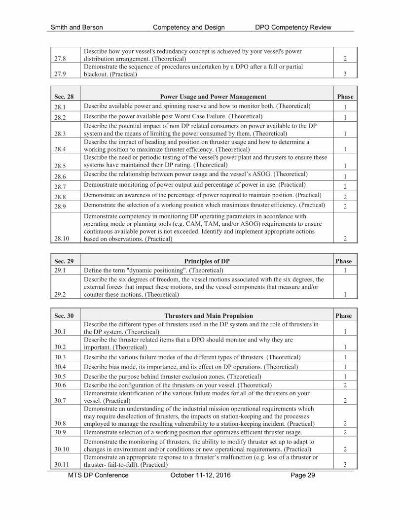
Smith and Berson Competency and Design DPO Competency Review
MTS DP Conference October 11-12, 2016 Page 29
27.8
Describe how your vessel's redundancy concept is achieved by your vessel's power distribution arrangement. (Theoretical)
2
27.9
Demonstrate the sequence of procedures undertaken by a DPO after a full or partial blackout. (Practical)
3
Sec. 28
Power Usage and Power Management
Phase
28.1 Describe available power and spinning reserve and how to monitor both. (Theoretical) 1
28.2 Describe the power available post Worst Case Failure. (Theoretical) 1 28.3
Describe the potential impact of non DP related consumers on power available to the DP system and the means of limiting the power consumed by them. (Theoretical)
1
28.4
Describe the impact of heading and position on thruster usage and how to determine a working position to maximize thruster efficiency. (Theoretical)
1
28.5
Describe the need or periodic testing of the vessel's power plant and thrusters to ensure these systems have maintained their DP rating. (Theoretical)
1
28.6 Describe the relationship between power usage and the vessel’s ASOG. (Theoretical) 1
28.7 Demonstrate monitoring of power output and percentage of power in use. (Practical) 2
28.8 Demonstrate an awareness of the percentage of power required to maintain position. (Practical) 2
28.9 Demonstrate the selection of a working position which maximizes thruster efficiency. (Practical) 2
28.10
Demonstrate competency in monitoring DP operating parameters in accordance with operating mode or planning tools (e.g. CAM, TAM, and/or ASOG) requirements to ensure continuous available power is not exceeded. Identify and implement appropriate actions based on observations. (Practical)
2
Sec. 29 Principles of DP Phase 29.1 Define the term "dynamic positioning". (Theoretical) 1
29.2
Describe the six degrees of freedom, the vessel motions associated with the six degrees, the external forces that impact these motions, and the vessel components that measure and/or counter these motions. (Theoretical)
1
Sec. 30 Thrusters and Main Propulsion Phase 30.1
Describe the different types of thrusters used in the DP system and the role of thrusters in the DP system. (Theoretical)
1
30.2
Describe the thruster related items that a DPO should monitor and why they are important. (Theoretical)
1
30.3 Describe the various failure modes of the different types of thrusters. (Theoretical) 1
30.4 Describe bias mode, its importance, and its effect on DP operations. (Theoretical) 1
30.5 Describe the purpose behind thruster exclusion zones. (Theoretical) 1 30.6 Describe the configuration of the thrusters on your vessel. (Theoretical) 2
30.7
Demonstrate identification of the various failure modes for all of the thrusters on your vessel. (Practical)
2
30.8
Demonstrate an understanding of the industrial mission operational requirements which may require deselection of thrusters, the impacts on station-keeping and the processes employed to manage the resulting vulnerability to a station-keeping incident. (Practical)
2 30.9 Demonstrate selection of a working position that optimizes efficient thruster usage. 2
30.10
Demonstrate the monitoring of thrusters, the ability to modify thruster set up to adapt to changes in environment and/or conditions or new operational requirements. (Practical)
2
30.11
Demonstrate an appropriate response to a thruster’s malfunction (e.g. loss of a thruster or thruster- fail-to-full). (Practical)
3

Smith and Berson Competency and Design DPO Competency Review
MTS DP Conference October 11-12, 2016 Page 30
Appendix 2, OSVDPA Scheme Progression and Certification Requirements.
Phase 1: Induction Course *The OSVDPA accepts Sea Time and Practical Experience earned on vessels with unclassed DP systems, provided the vessel has been approved by the OSVDPA as an Accepted Unclassed Vessel (AUV).
Five Day Course or Blended Online/Classroom Course
Written Assessment**
Phase 2: Familiarization
30 Days Sea-Time and 90 Hours Practical Experience*
Completion of Taskbook
Phase 3: Simulator Course
Four or Five Day Course
Simulator-Based Assessment**
Class C DPO Permit (Optional)
Holders progress to Phase 4A or 4B
Phase 4B: Watchkeeping Class B DPO Certificate Track
Phase 4A: Watchkeeping Class A DPO Certificate Track
60 Days Sea-Time and 180 Hours Practical Experience on AUV or Classed DP-1 Vessel*
60 Days Sea-Time and 180 Hours Practical Experience on a classed DP-2 or 3 Vessel
Onboard or Simulator-Based Assessment Onboard or Simulator-Based Assessment
Class B DPO Certificate
Class A DPO Certificate
Phase 5: Class B DPO Certificate Upgrade
30 Days Sea-Time and 60 Hours Practical Experience on classed DP-2 or 3 Vessel
Onboard or Simulator-Based Assessment
**The Phase 1 and Phase 3 assessments are conducted at training centers. The first attempt at passing the assessments must be completed at the time the course is taken, at the training center where the course was taken.
White arrows signify times when prospective DPOs must submit their logbook and supporting documentation to the OSVDPA for validation. Blue arrows signify progression when no validation is necessary.
Completion of the taskbook
Completion of the taskbook Completion of the taskbook
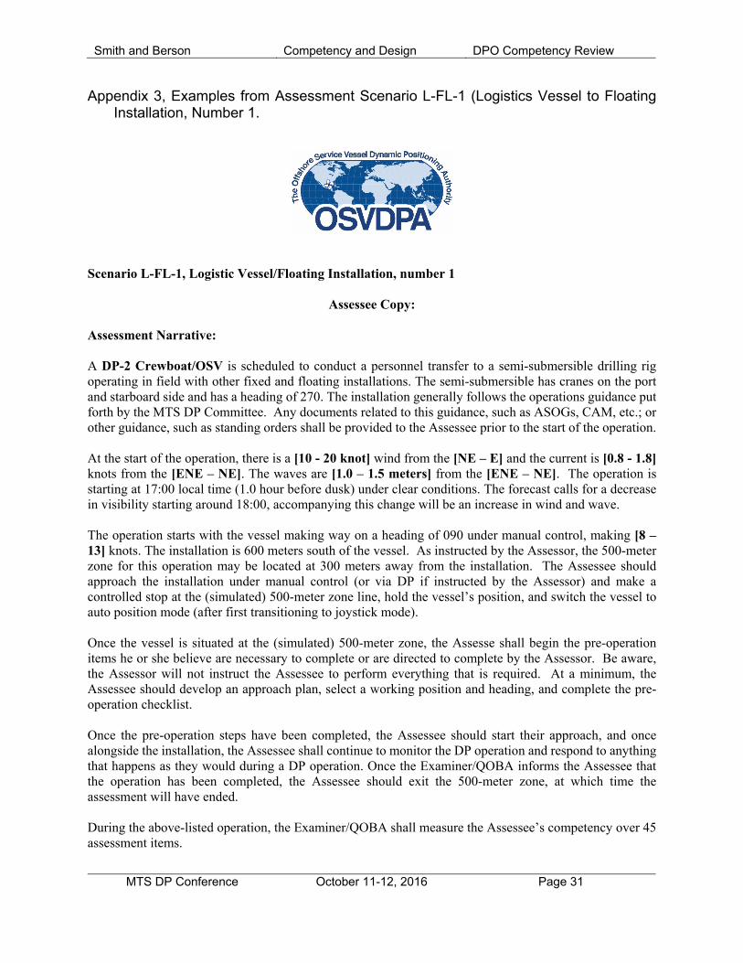
Smith and Berson Competency and Design DPO Competency Review
MTS DP Conference October 11-12, 2016 Page 31
Appendix 3, Examples from Assessment Scenario L-FL-1 (Logistics Vessel to Floating Installation, Number 1.
Scenario L-FL-1, Logistic Vessel/Floating Installation, number 1
Assessee Copy: Assessment Narrative: A DP-2 Crewboat/OSV is scheduled to conduct a personnel transfer to a semi-submersible drilling rig operating in field with other fixed and floating installations. The semi-submersible has cranes on the port and starboard side and has a heading of 270. The installation generally follows the operations guidance put forth by the MTS DP Committee. Any documents related to this guidance, such as ASOGs, CAM, etc.; or other guidance, such as standing orders shall be provided to the Assessee prior to the start of the operation. At the start of the operation, there is a [10 - 20 knot] wind from the [NE – E] and the current is [0.8 - 1.8] knots from the [ENE – NE]. The waves are [1.0 – 1.5 meters] from the [ENE – NE]. The operation is starting at 17:00 local time (1.0 hour before dusk) under clear conditions. The forecast calls for a decrease in visibility starting around 18:00, accompanying this change will be an increase in wind and wave. The operation starts with the vessel making way on a heading of 090 under manual control, making [8 – 13] knots. The installation is 600 meters south of the vessel. As instructed by the Assessor, the 500-meter zone for this operation may be located at 300 meters away from the installation. The Assessee should approach the installation under manual control (or via DP if instructed by the Assessor) and make a controlled stop at the (simulated) 500-meter zone line, hold the vessel’s position, and switch the vessel to auto position mode (after first transitioning to joystick mode). Once the vessel is situated at the (simulated) 500-meter zone, the Assesse shall begin the pre-operation items he or she believe are necessary to complete or are directed to complete by the Assessor. Be aware, the Assessor will not instruct the Assessee to perform everything that is required. At a minimum, the Assessee should develop an approach plan, select a working position and heading, and complete the pre-operation checklist. Once the pre-operation steps have been completed, the Assessee should start their approach, and once alongside the installation, the Assessee shall continue to monitor the DP operation and respond to anything that happens as they would during a DP operation. Once the Examiner/QOBA informs the Assessee that the operation has been completed, the Assessee should exit the 500-meter zone, at which time the assessment will have ended. During the above-listed operation, the Examiner/QOBA shall measure the Assessee’s competency over 45 assessment items.
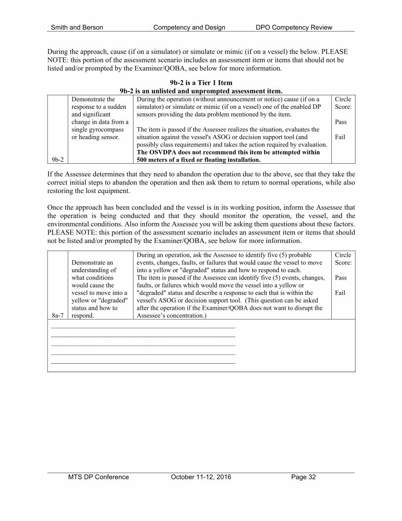
Smith and Berson Competency and Design DPO Competency Review
MTS DP Conference October 11-12, 2016 Page 32
During the approach, cause (if on a simulator) or simulate or mimic (if on a vessel) the below. PLEASE NOTE: this portion of the assessment scenario includes an assessment item or items that should not be listed and/or prompted by the Examiner/QOBA, see below for more information.
9b-2 is a Tier 1 Item 9b-2 is an unlisted and unprompted assessment item.
9b-2
Demonstrate the response to a sudden and significant change in data from a single gyrocompass or heading sensor.
During the operation (without announcement or notice) cause (if on a simulator) or simulate or mimic (if on a vessel) one of the enabled DP sensors providing the data problem mentioned by the item. The item is passed if the Assessee realizes the situation, evaluates the situation against the vessel's ASOG or decision support tool (and possibly class requirements) and takes the action required by evaluation. The OSVDPA does not recommend this item be attempted within 500 meters of a fixed or floating installation.
Circle Score: Pass Fail
If the Assessee determines that they need to abandon the operation due to the above, see that they take the correct initial steps to abandon the operation and then ask them to return to normal operations, while also restoring the lost equipment. Once the approach has been concluded and the vessel is in its working position, inform the Assessee that the operation is being conducted and that they should monitor the operation, the vessel, and the environmental conditions. Also inform the Assessee you will be asking them questions about these factors. PLEASE NOTE: this portion of the assessment scenario includes an assessment item or items that should not be listed and/or prompted by the Examiner/QOBA, see below for more information.
8a-7
Demonstrate an understanding of what conditions would cause the vessel to move into a yellow or "degraded" status and how to respond.
During an operation, ask the Assessee to identify five (5) probable events, changes, faults, or failures that would cause the vessel to move into a yellow or "degraded" status and how to respond to each. The item is passed if the Assessee can identify five (5) events, changes, faults, or failures which would move the vessel into a yellow or "degraded" status and describe a response to each that is within the vessel's ASOG or decision support tool. (This question can be asked after the operation if the Examiner/QOBA does not want to disrupt the Assessee’s concentration.)
Circle Score: Pass Fail
________________________________________________________ ________________________________________________________ ________________________________________________________ ________________________________________________________ ________________________________________________________