draft may 2009 - idaho
TRANSCRIPT

Design & Construction Guidelines
DRAFT May 2009

Authors/Contributors
Robert Otto Rasmussen, PhD, INCE, PE (TX) The Transtec Group, Inc.
Richard Rogers, PE (TX) The Transtec Group, Inc.
Theodore R. Ferragut, PE (VA) TDC Partners, Ltd.
Sponsors
Federal Highway Administration
Concrete Reinforcing Steel Institute

ACKNOWLEDGMENTSThis manual is the result of a cooperative effort between the Federal Highway Administration’s (FHWA) Office of Pavement Technology and the Concrete Reinforcing Steel Institute (CRSI). The author/contributor team is grateful for the support of these two organizations in developing this much-needed resource.
The team also appreciates the invaluable advice and input provided by several State departments of transportation, academia, and the concrete pavement industry as repre-sented by the American Concrete Pavement Association who participated in an FHWA-CRSI expert task group. Their responses to drafts of the document resulted in a tighter, more focused and technically sound manual. Members of the task group include the following:
Steve Tritsch and Mike Plei, CMC Sam Tyson, FHWA A.J. Jubran, Georgia Department of Transportation Wouter Gulden, ACPA-SE
Bill Farnbach, Caltrans Dan Zollinger, Texas A&M Jeff Roesler, U of IL – Champaign Mohamed Elfino, Virginia Department of Transportation Chetana Rao, ARA Bethany Walker, CRSIMoon Won, Texas Tech University Norbert DeLatte, Cleveland State University Tom Cackler, National Center for Concrete Pavement
Technology Darren Szrom, CRSI Leif Wathne, ACPABob Risser, CRSI Jeff Dean, Oklahoma Department of Transportation Lisa Lukefahr, Texas Department of Transportation Rene Renteria, Oregon Department of Transportation Doc Zhang, Louisiana Department of Transportation and
DevelopmentSuneel Vanikar, FHWA


May 2009 - DRAFT LAYOUT v
PREFACEContinuously reinforced concrete pavements (CRCP) were introduced in 1921 when the U.S. Bureau of Public Roads built a CRCP section on the Columbia Pike near Arlington, Virginia. Since then CRCP has become standard construc-tion practice in several States, including Illinois, Texas, and Oregon. Many European countries, Japan, and Australia also construct CRCP.
During the 70-plus years that CRCP has been common practice, various lessons learned through research and practical experience have contributed to improved design methods, materials selection, and construction practices.
Today CRCP can be designed and constructed consistently and reliably to provide superior long-term performance with very low maintenance.
This manual provides information about current practices for designing and constructing CRCP. The information has been collected and synthesized from formal research results and from the most knowledgeable technical experts and practitioners in the country. The manual focuses on char-acteristics and practices unique to CRCP, including general information about concrete pavement design, materials, and construction when necessary to provide context.


May 2009 - DRAFT LAYOUT vii
TABLE OF CONTENTSACKNOWLEDGMENTS iiiPREFACE vTABLE OF CONTENTS viiLIST OF FIGURES xiLIST OF TABLES xv
CHAPTER 1: INTRODUCTION AND OVERVIEW 1
What is CRCP? 3When and Why is CRCP Used? 3Overview of Key Points for CRCP 4
CHAPTER 2: CRCP DESIGN OVERVIEW 7
Background 9Objectives 9Scope of the Design Guidelines 9
CHAPTER 3 CRCP DESIGN FUNDAMENTALS 11
CRCP Behavior 13Crack Spacing 14Crack Width 14Reinforcement Stress 15Other Factors affecting CRCP Behavior 15
Structural and Functional Performance Indicators 15Punchouts 15Spalling 16Smoothness 16
CHAPTER 4: CRCP DESIGN INPUTS 17
Design Criteria 19Limiting Criteria on Crack Spacing, Crack Width, and Steel Stress 19Structural Performance 20Functional Performance 20
Concrete Properties 20
Reinforcement Type and Properties 21
Pavement Support 22Bases 22Subgrades 23Drainage 23
Climate 23
Traffic 24
CHAPTER 5: DESIGN OF CRCP FEATURES 25
CRCP Design Methods 27AASHTO-86/93 Design Procedure 27AASHTO Interim MEPDG 27
Early-Age Behavior Analysis Tools 29HIPERPAV II 29PowerPave 29
Evaluation of Critical Stresses 29
Concrete Thickness 29Longitudinal Reinforcement 30

Continuousely Reinforced Concrete Pavement Design and Construction Guidelinesviii
Reinforcement Content 30Bar Size and Spacing 31Vertical Position of Reinforcement 33Lap Splices 33Corrosion Protection 34
Transverse Reinforcement 35Size and Spacing 35Tiebars 35
Joints 36Longitudinal Joints 37Transverse Construction Joints 38Transition or Terminal Joints 38
Terminal End Anchor Joints 38Wide-Flange Beam Joints 39
Other Design Details 40Crossovers 40Shoulders 41Ramps and Auxiliary Lanes 41Intersections 43
CHAPTER 6: CRCP CONSTRUCTION OVERVIEW 45
Contracting for Innovation 47
CHAPTER 7: CRCP SUPPORT CONSTRUCTION 49
Base Layers 51Asphalt-Stabilized Base 51Cement-Treated Base 52Lean Concrete Base 53Dense-Graded Granular Base and Subbase 53Open-Graded Permeable Base 54
Edge Drains and Impervious Moisture Barriers 54
CHAPTER 8: REINFORCEMENT 57
Characteristics of Reinforcing Steel 59Longitudinal Reinforcement 59
Bar Size and Quantity 60Bar Spacing and Depth 60Bar Splices 60
Transverse Reinforcement 61Bar Size and Quantity 61
Transverse Reinforcement 62Bar Size and Quantity 62
Tiebars 62
Placing Reinforcement 63Manual Steel Placement (Chairs or Transverse Bar Assembly) 64Mechanical Steel Placement (Tube-feeding) 65
Inspection 66
Troubleshooting and Precautions 67
CHAPTER 9: PAVING PRACTICES FOR CRCP 69Aggregates 71
Placing 71
Consolidation 72

Joints 72Longitudinal Control Joints 72Longitudinal Free Joints 72Transverse Construction Joints 72Blockouts 74Construction Techniques for Controlling Crack Spacing 74
Fast-Track Paving 74
Environmental Influences during Construction 75Hot Weather Conditions 75Concrete Placement Time and Season 75
Using FHWA HIPERPAV and CRSI PowerPave 75
CHAPTER 10: TERMINAL OR TRANSITION TREATMENTS 77
Expansion Joints 79
Wide-Flange Beam Joints 80
Anchor Lugs 81
Seamless Transitions 82
CHAPTER 11: CONSTRUCTING CROSSOVERS 83
Leave-Ins 85
Leave-Outs 85
Temporary Crossovers 85
CHAPTER 12: CONSTRUCTING SHOULDERS AND RAMPS 87
Shoulders and Auxiliary Lanes 89Concrete Shoulders 89Asphalt Shoulders 89Widened Lane 90
Concrete Ramps 90
CHAPTER 13: CRCP OVERLAY CONSTRUCTION 91
CHAPTER 14: CONSTRUCTION INSPECTION 95
CHAPTER 15: GUIDE SPECIFICATIONS FOR CRCP 103
Materials 105Coarse Aggregate 105Reinforcement 105
Bar Specifications 105Length of Reinforcing Bars 106Size and Spacing of Reinforcing Bars 106
Equipment 106
Construction Methods 106Placement of Reinforcement 106
Reinforcing Bars Placed Manually on Chairs 106Reinforcing Bars Placed Mechanically Using a Tube Feeder 107
Placement of Concrete 107Joint and Terminal Construction 107
Longitudinal Joints 107Transverse Construction Joints 107Wide-Flange Beam Terminal Joints 108Anchor Lug Terminal Joints 108

Final Strike-off, Consolidation, and Finishing 108
Method of Measurement 108
Basis for Payment 108
APPENDIX A: INNOVATIONS AND STATE DOT DESIGN DETAILS 111
Specifications for CRCP Temperature Management 113
Texas DOT Design Standards 115
Illinois DOT Design Standards 121
Composite Pavements 129
APPENDIX B: AASHTO-86/93 GUIDE REINFORCEMENT DESIGN 131
Longitudinal Reinforcement Design Inputs 133Concrete Tensile Strength 133Concrete Coefficient of Thermal Expansion 133Concrete Drying Shrinkage 133Reinforcing Bar Diameter 133Steel Coefficient of Thermal Expansion 133Design Temperature Drop 133Wheel Load Tensile Stress 133
Longitudinal Reinforcement Design Procedure 133
APPENDIX C: GLOSSARY 139
APPENDIX D: REFERENCES 147

May 2009 - DRAFT LAYOUT xi
LIST OF FIGURESFigure 1. Newly constructed CRCP in Virginia 3
Figure 2. Reinforcement design is critical to good performance 4
Figure 3. Concrete design and mix materials are critical to good performance 4
Figure 4. Typical CRCP cross section 5
Figure 5. Schematic representation of some of the factors influencing CRCP behavior. 13
Figure 6. Typical CRCP punchout distress. 14
Figure 7. Spalling along transverse crack in a CRCP. 16
Figure 8. Structural performance in terms of punchouts as a function of time or traffic loads. 20
Figure 9. Functional performance in terms of IRI as a function of time or traffic loads. 20
Figure 10. Framework of CRCP design procedure in the AASHTO Interim MEPDG.(29) 28
Figure 11. Conceptual representation of steel design for CRCP.(55) 30
Figure 12. Reinforcement spacing recommendations. 32
Figure 13. Two-layered steel reinforcement mat. 33
Figure 14. Typical layout pattern with laps skewed across pavement. 34
Figure 15. Longitudinal construction joint with multiple piece tiebars. 37
Figure 16. Longitudinal contraction (hinged) joint with transverse bars. 37
Figure 17. Transverse construction joint. 38
Figure 18. Wide-flange beam joint detail. 39
Figure 19. Layout of reinforcement in leave-out section.(58) 40
Figure 20. Recommended layouts for ramp connections. 42
Figure 21. Jointing details for ramp connections. 42
Figure 22. Design detail for CRCP intersection.(67) 43
Figure 23. Edge punchout in CRCP. 47
Figure 24. Asphalt-stabilized base. (photo courtesy of Zachry Constrution) 51
Figure 25. Placing geotextile interlayer in Germany. 52
Figure 26. Fastener for geotextile interlayer. 52
Figure 27. Core taken showing pavement with geotextile interlayer. 52
Figure 28. Trimming and compacting granular base. 53
Figure 29. Typical vertical moisture barrier configuration. 55
Figure 30. Example of the ASTM marking requirements for a #8, Grade 60 (#25, Grade 420) bar. 59
Figure 31. Mill and coating certifications for rebar. 59
Figure 32. Longitudinal steel reinforcement in Virginia. 60

Figure 33. Epoxy-coated steel reinforcement. 60
Figure 34. Lap splices. 60
Figure 35. Typical lap splice patterns. 61
Figure 36. Longitudinal sawed joint with tiebars. 62
Figure 37. Longitudinal construction joint with tiebars. 62
Figure 38. Multiple-piece threaded tiebars. 62
Figure 39. Mechanical tiebar inserter. (Photo courtesy of HDR) 63
Figure 40. Protective coating on tiebar midsections. 63
Figure 41. Paver with steel on chairs. 64
Figure 42. Worker walking on reinforcing steel in Virginia. 64
Figure 43. Example of steel placed on chairs in Texas. 65
Figure 44. Example with two layers of steel placed on chairs. 65
Figure 45. Mechanical steel placement using tubes. 65
Figure 46. Checking reinforcement lap. 66
Figure 47. Checking steel placement. 66
Figure 48. Checking for steel movement. 66
Figure 49. Probing the fresh concrete to check the steel depth. 67
Figure 50. Effect of coarse aggregate size on crack roughness variation with slab depth. 71
Figure 51. High-speed belt discharge in Virginia. 71
Figure 52. Longitudinal free joint. 72
Figure 53. Transverse (start) construction joint. 73
Figure 54. Transverse construction joint (header). 73
Figure 55. CRCP Blockout Schematic. 74
Figure 56. Expansion Joint, CRCP to JCP or a bridge. 79
Figure 57. Expansion joint, CRCP to HMA. 80
Figure 58. Expansion joint, CRCP to HMA alternative. 80
Figure 59. Typical wide flange beam terminal joint system used in Illinois. 80
Figure 60. Typical anchor lug terminal joint system.(85) 81
Figure 61. Seamless pavement transition for bridges. 82
Figure 62. Conceptual approach for CRCP temperature management end-result specification.(48) 113
Figure 63. Texas design standard for CRCP one layer steel bar placement for slab thicknesses under 14 in (356 mm). 116
Figure 64. Texas design standard for CRCP two layer steel bar placement for 14 and 15 in (356 and 381 mm) slab thicknesses. 117
Figure 65. Texas design standard for CRCP terminal anchor lugs. 118

May 2009 - DRAFT LAYOUT xiii
Figure 66. Texas design standard for bridge approach slab (sheet 1 of 2). 119
Figure 67. Texas design standard for bridge approach slab (sheet 2 of 2). 120
Figure 68. Illinois design standard for CRCP bar reinforcement. 122
Figure 69. Illinois design standard for 24 ft (7.2 m) CRCP with wide flange beam transition joint (sheet 1 of 2). 123
Figure 70. Illinois design standard for 24 ft (7.2 m) CRCP with wide flange beam transition joint (sheet 2 of 2). 124
Figure 71. Illinois design standard for bridge approach pavement (sheet 1 of 4). 125
Figure 72. Illinois design standard for bridge approach pavement (sheet 2 of 4). 126
Figure 73. Illinois design standard for bridge approach pavement (sheet 3 of 4). 127
Figure 74. Illinois design standard for bridge approach pavement (sheet 4 of 4). 128
Figure 75. Chart for estimating wheel load tensile stress. 134
Figure 76. Minimum percent longitudinal reinforcement to satisfy crack width criterion. 135
Figure 77. Percent of longitudinal reinforcement to satisfy crack spacing criteria. 136
Figure 78. Minimum percent longitudinal reinforcement to satisfy steel stress criteria. 137


May 2009 - DRAFT LAYOUT xv
LIST OF TABLESTable 1. Allowable steel working stress, ksi (MPa).(5) 19
Table 2. Weight and dimensions of ASTM standard reinforcing steel bars.(31) 22
Table 3. ASTM standard grades for reinforcing steel bars.(31) 22
Table 4. Friction coefficients for different base materials.(5) 35
Table 5. Wide-flange (WF) beam (weight and dimensions) (56) 39
Table 6. Summary of Inspection Tasks. 97
Table 6. Summary of Inspection Tasks. (continued) 98
Table 6. Summary of Inspection Tasks. (continued) 99
Table 6. Summary of Inspection Tasks. (continued) 100
Table 6. Summary of Inspection Tasks. (continued) 101
Table 7. Typical CTE for concrete made with common aggregate types. 133
Table 8. Approximate relationship between shrinkage and indirect tensile strength of concrete.(5) 133


CHAPTER 1
INTRODUCTION AND OVERVIEW


May 2009 - DRAFT LAYOUT 3
What is CRCP?Continuously reinforced concrete pavements (CRCP) con-tain continuous longitudinal reinforcement, usually steel, and do not have transverse joints except where necessary for construction purposes (e.g., end-of-day construction header joints) or at bridge approaches or transitions to other pave-ment structures.
Continuous reinforcement is a strategy for managing the transverse cracking that occurs in all new concrete pave-ments. In new concrete, natural volume changes due to cement-water hydration are restrained by the pavement base and other physical features adjacent to the concrete, causing stresses to develop in the concrete. These stresses build faster than the concrete’s strength so, at some point, full-depth cracks form, effectively dividing the pavement into indi-vidual slabs.
Unlike jointed plain concrete pavements (JPCP), where the number and location of transverse cracks are managed by sawing or constructing joints, in CRCP the continuous reinforcement allows transverse cracks to occur relatively closely together and holds them tightly closed for maximum
aggregate interlock. As a result, load transfer between pave-ment slabs is maximized, and flexural (bending) stresses due to traffic loads and curling and warping are minimized.
In CRCP, longitudinal joints may be used to relieve concrete stresses in the transverse direction, for example when the paving width exceeds 14 ft. To hold any longitudinal cracks that may form tightly closed, CRCP commonly contains transverse reinforcement as well.
When and Why is CRCP Used?Continuously reinforced concrete can be an excellent pave-ment solution for heavily traveled and loaded roadways, including interstate highways (Figure 1). Well designed and constructed CRCPs accomplish the following:
Eliminate joint-maintenance costs for the life of the pave-•ment, helping meet the public’s desire for reduced work zones and related traveler delays.
Provide consistent transfer of shear stresses from heavy •wheel loads, resulting in consistently quiet ride and less distress development at the cracks.
Figure 1. Newly constructed CRCP in Virginia

Continuousely Reinforced Concrete Pavement Design and Construction Guidelines4
Such pavements can be expected to provide over 40 years of exceptional performance with minimal maintenance. These attributes are becoming increasingly important in high-traf-fic, heavy-truck areas, where delays are costly and a smooth ride is expected. Some of the most highly trafficked road-ways in the country—including Interstate 75 in Atlanta, I-90 and I-94 in Chicago, and I-45 in Houston—demon-strate CRCP’s rugged, low-maintenance performance.
Data from the FHWA’s Long Term Pavement Performance (LTPP) program show that the large majority of heavily-trafficked sections of CRCP projects in 22 States have main-tained their smoothness for 20 to 30 years and more.
CRCP can be easily widened to provide additional capacity and, after many years of service, can be overlaid with either concrete or asphalt.
Overview of Key Points for CRCPSome States, including Illinois and Texas, have finetuned their CRCP design and construction techniques, resulting in lower life-cycle costs and increased public satisfaction.
Following is a brief list of key practices that help ensure suc-cessful CRCP projects:
Design, mix, and construction decisions and practices •(Figure 2 and 3) should maximize load-transfer efficiency and minimize flexural stresses.
Cracks that are closely spaced (3-4 ft. maximum is •optimum) and tight (0.2 in. at the depth of the reinforce-ment) help maximize load-transfer efficiency and mini-mize flexural stresses, maintaining steel stress well below the yield strength.
Figure 3. Concrete design and mix materials are critical to good performance
Figure 2. Reinforcement design is critical to good perfor-mance
Closely spaced, tight cracks result when the project •includes
Adequate longitudinal steel content (0.6 to 0.8 percent ºof the slab cross-section area).
Optimum reinforcement diameter. º
Adequate lapping of reinforcement splices. º
Appropriate depth of reinforcement placement. º
Thorough consolidation of concrete around the ºreinforcement,
Reinforcement design has to consider possible fracture •and/or excessive plastic deformation. Stress in the rein-forcement is usually limited to a reasonable percentage of the ultimate tensile strength to avoid fracture and limit the amount of plastic deformation.
Large, abrasion-resistant aggregates promote good aggre-•gate interlock and thus enhance load-transfer efficiency.
Sufficient slab thickness is required to manage trans-•verse tensile stresses due to truck traffic and curling and warping.
The foundation must be uniform and stable, provide •good drainage, and extend beyond the slab edge through the shoulder area and through transitions at bridge approaches, cuts, and fills.
Longitudinal construction joints must be tied to adjacent •pavement at centerline or shoulder.
Longitudinal contraction joints at shoulders should be •sawed directly over the transverse reinforcement.
Curing should be thorough and appropriate to each •CRCP application, weather conditions, etc.

May 2009 - DRAFT LAYOUT 5
CL
Improved SubgradeAggregate Subbase150 mm (6 in.)
Asphalt Base25 to 100 mm (1 to 4 in.) typical
Passing Lane3.5m (12 ft.)
Driving Lane3.5m (12 ft.)
Base Extension0.6m (2 ft.)
Base Extension0.6m (2 ft.)
CRCP250 mm (10in.)
0.085% transverse steel 0.7% longitudinal steel
Steel between mid-depth to 90mm (3.5 in.) below surface
Sawed Longitudinal Joint
Figure 4. Typical CRCP cross section
Many practices from the above list are illustrated in Fig-ure 4, a typical modern CRCP cross section. Ongoing
research, field monitoring, and materials innovations will likely result in additional refinements to these practices.


CHAPTER 2
CRCP DESIGN OVERVIEW

May 2009 - DRAFT LAYOUT 9
BackgroundA recent survey on CRCP design practices in the US indi-cated that most States that commonly use this pavement type use the AASHTO design procedure published in 1986 (and later in 1993). One exception is Illinois, which uses a modified version of this method.(4,5) While there are differ-ences in the overlay design, the core of the pavement design procedures found in both the 1986 and 1993 editions is the same. Therefore, the guidelines presented herein refer to this method as the “AASHTO-86/93” design procedure.
Since the development of the AASHTO-86/93 design procedures, a number of new findings have been reported based on research conducted around the world. Some of these findings include improved practices based on a FHWA research study where CRCP sections in several states were evaluated.(6-12) Additional findings have been reported from evaluation of sections in the LTPP database.(13,14) Other experimental and field studies performed by indi-vidual States and around the world have also contributed to updates in CRCP design.(15,16,17)
It is important that pavement design engineers in the US are aware of such findings, as they may very likely have an impact on the performance of CRCP that can translate into cost-effective pavement solutions.
ObjectivesWith the above considerations, this section of the guidelines is intended to provide updated design guidelines based on recent findings. These guidelines address available design methodologies, and include both state-of-the-practice and
state-of-the-art recommendations. Guidance is included on the selection of design inputs, pavement performance cri-teria, and recommendations for different CRCP structural elements.
These guidelines are not in and of themselves a design method, but should instead be considered a synthesis of bet-ter design practices. It should be noted that at the time of writing this document, the interim AASHTO Mechanistic Empirical Pavement Design Guide (MEPDG) is currently being evaluated by State DOTs. While findings from these evaluations are ongoing, the authors have taken measures to incorporate a reasonable amount of relevant information in order to provide a preview of how this may affect CRCP design.
Scope of the Design GuidelinesThe Design Section is divided into the following sections.
Section 2 discusses CRCP Design fundamentals; this section provides a brief introduction on CRCP behavior followed by structural and functional criteria that should be consid-ered during design.
Section 3 expands on the factors that should be considered during the design stage that are known to have an impact on CRCP performance, such as reinforcement type, pave-ment support, climate, and traffic.
Section 4 discusses the design of CRCP features; this section provides recommendations on the selection and sizing of various CRCP features including thickness, reinforcement, joints, and shoulders.


CHAPTER 3
CRCP DESIGN FUNDAMENTALS


May 2009 - DRAFT LAYOUT 13
Designing a CRCP involves dimensioning the different geo-metric pavement features such as thickness, longitudinal and transverse reinforcement, construction joints, slab width, shoulders, and pavement transitions based on site-specific traffic, climatic, and foundation parameters. The designer selects pavement designs that will be suitable to achieve the desired performance level for the design period selected. As in all pavement designs, the goal is to use locally available materials to the greatest extent possible, but without com-promising pavement performance.
The crack spacing, crack width, steel stress, and bond development length generated as a function of reinforce-ment restraint and climatic conditions each affect the CRCP structural integrity in the long term. It is important that precautions are taken during the CRCP design, materials selection, and construction process so that a crack pat-tern develops that minimizes development of pavement distresses.
It should also be noted that many of these design aspects described herein are common to all concrete pavements – not just CRCP. As a result, and for brevity, some aspects of concrete pavement design will not be expanded upon herein. Instead, guidance should be sought from the appro-priate design references such as the AASHTO-86/93 Guide. That said, the following sections provide a description of the factors affecting crack patterns that develop in early-age CRCP, and further discuss the impact that this CRCP behavior has on pavement performance. Additional infor-mation on structural and functional performance factors are also given.
CRCP Behavior Following construction of a CRCP, a number of mecha-nisms influence development of stresses in the slab and thus the formation of cracks. Figure 5 provides a schematic repre-sentation of some of the factors influencing CRCP behavior. During the early age, temperature and moisture fluctuations induce volume changes in the concrete that are restrained by reinforcement and base friction, leading to the development of stresses.
Since concrete is weak in tension, whenever the stresses that develop are higher than the tensile strength of the concrete, transverse cracks form to relieve the stresses. Reinforcement serves to keep cracks closed as keeping the cracks tight is essential in maintaining load transfer through aggregate interlock. This, in turn, reduces pavement flexural stresses due to traffic loading.
Tight cracks are also beneficial to avoid water infiltra-tion and intrusion of incompressibles through the cracks. Subsequent drops in temperature and the effect of drying shrinkage in the concrete tend to reduce the transverse crack spacing further. Externally-induced stresses due to wheel loads, and subsequent seasonal (climatic) changes, further reduce the crack spacing over time, but at a much slower rate. Overall, it has been observed that the crack spacing decreases rapidly during the early age of the pavement, up until about one or two years. After this stage, the transverse cracking pattern remains constant until the slab reaches the end of its fatigue life.
Figure 5. Schematic representation of some of the factors influencing CRCP behavior.
Crack spacing
Reinforcement
Slab ThicknessBase
Slab/Base restraint
Traffic loadsCrack spacing
Reinforcement
Slab ThicknessBase
Slab/Base restraint
Traffic loads
Aggregate Interlock
Crack width
Aggregate Interlock
Crack width
Continuousely Reinforced Concrete Pavement Design and Construction Guidelines14
The primary early-age pavement indicators of performance on CRCP include crack spacing, crack width, and steel stress. The following sections describe these indicators in more detail.
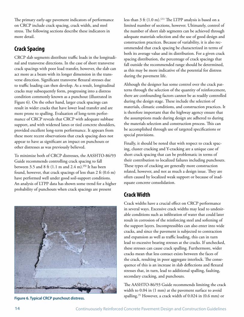
Crack SpacingCRCP slab segments distribute traffic loads in the longitudi-nal and transverse directions. In the case of short transverse crack spacings with poor load transfer, however, the slab can act more as a beam with its longer dimension in the trans-verse direction. Significant transverse flexural stresses due to traffic loading can then develop. As a result, longitudinal cracks may subsequently form, progressing into a distress condition commonly known as a punchout (illustrated in Figure 6). On the other hand, larger crack spacings can result in wider cracks that have lower load transfer and are more prone to spalling. Evaluation of long-term perfor-mance of CRCP reveals that CRCP with adequate subbase support, and with widened lanes or tied concrete shoulders, provided excellent long-term performance. It appears from these more recent observations that crack spacing does not appear to have as significant an impact on punchouts or other distresses as was previously believed.
To minimize both of CRCP distresses, the AASHTO-86/93 Guide recommends controlling crack spacing to fall between 3.5 and 8 ft (1.1 m and 2.4 m).(5) It has been found, however, that crack spacings of less than 2 ft (0.6 m) have performed well under good soil-support conditions. An analysis of LTPP data has shown some trend for a higher probability of punchouts when crack spacings are present
less than 3 ft (1.0 m).(21) The LTPP analysis is based on a limited number of sections, however. Ultimately, control of the number of short slab segments can be achieved through adequate materials selection and the use of good design and construction practices. Because of variability, it is also rec-ommended that crack spacing be characterized in terms of both its average value and its distribution. For a given crack spacing distribution, the percentage of crack spacings that fall outside the recommended range should be determined, as this may be more indicative of the potential for distress during the pavement life.
Although the designer has some control over the crack pat-terns through the selection of the quantity of reinforcement, there are confounding factors cannot be as readily controlled during the design stage. These include the selection of materials, climatic conditions, and construction practices. It is therefore important that the highway agency ensure that the assumptions made during design are adhered to during the materials selection and construction process. This can be accomplished through use of targeted specifications or special provisions.
Finally, it should be noted that with respect to crack spac-ing, cluster cracking and Y-cracking are a unique case of short crack spacing that can be problematic in terms of their contribution to localized failures including punchouts. These types of cracking are generally more construction related, however, and not as much a design issue. They are often caused by localized weak support or because of inad-equate concrete consolidation.
Crack Width Crack widths have a crucial effect on CRCP performance in several ways. Excessive crack widths may lead to undesir-able conditions such as infiltration of water that could later result in corrosion of the reinforcing steel and softening of the support layers. Incompressibles can also enter into wide cracks, and since the pavement is subjected to contraction and expansion as well as traffic loading, this can in turn lead to excessive bearing stresses at the cracks. If unchecked, these stresses can cause crack spalling. Furthermore, wider cracks mean that less contact exists between the faces of the crack, resulting in poor aggregate interlock. The conse-quence of this is an increase in slab deflections and flexural stresses that, in turn, lead to additional spalling, faulting, secondary cracking, and punchouts.
The AASHTO-86/93 Guide recommends limiting the crack width to 0.04 in (1 mm) at the pavement surface to avoid spalling.(5) However, a crack width of 0.024 in (0.6 mm) or Figure 6. Typical CRCP punchout distress.

May 2009 - DRAFT LAYOUT 15
less has been found to be effective in reducing water pen-etration, thus minimizing corrosion of the steel and main-taining a high load transfer efficiency.(22,23) As is done to con-trol crack spacing, the designer may select a reinforcement percentage that achieves a desired crack width. However, it is ideal if the highway agency further ensure that assump-tions made in design are adopted during construction.
In general, a higher percentage of longitudinal steel leads to smaller crack widths. The results of field performance evalu-ations have found that an adequate amount of longitudinal steel in the range of 0.6% to 0.85% effectively keeps crack widths reasonably tight throughout the pavement life.
The depth of the reinforcement is another important factor in controlling crack width. Major experiments in Illinois show that when reinforcement is placed above mid-depth, the cracks are more narrow leading to fewer punchouts and repairs over the long term. For reasons of adequate cover, reinforcement should not be placed closer than approxi-mately 3.5 to 4 in (89 to 101 mm) from the surface of the CRCP.
Reinforcement StressThe level of stress that develop in both the concrete and reinforcement will also influence CRCP performance in the long term. As stated before, the reinforcement serves to restrain volume changes in the concrete, keeping cracks tight. Consequently, significant stresses develop in the rein-forcement at the crack locations. Reinforcement design has to consider possible fracture and/or excessive plastic defor-mation at these locations. Excessive yield or fracture of the reinforcement may lead to wide cracks, corrosion, and loss of load transfer that may later result in undesirable distress.
It is common for a limiting stress criterion to be used for reinforcement design. This is often selected as a fixed percentage of the ultimate tensile strength, thus avoiding fracture, and allowing only a small probability of plastic deformation.(5,24) It should be recognized in design that slightly wider crack openings may result when permanent deformation is allowed to occur.
Other Factors affecting CRCP BehaviorIt is known that crack spacing, crack width, and reinforce-ment stress are also a function of other factors. Concrete tensile strength compared to the level of stresses that result from the restraint to volume changes is one example. Any factor that affects the tensile strength, or other factors such as slab restraint will contribute to volume changes (or the
restriction thereof ). These will also have an effect on the cracking characteristics of CRCP.
Structural and Functional Performance IndicatorsThe following sections expand on CRCP structural and functional performance indicators. These indicators are sometimes used as design criteria. These factors should not only be considered during the design stage, but also con-trolled through construction specifications if possible. The result will be a pavement structure that is capable of accom-modating the expected traffic and environmental loading.
PunchoutsA punchout is a type of distress that typically occurs between closely spaced transverse cracks in CRCP. It is defined as a block or wedge of CRCP that is delimited by two contiguous transverse cracks, a longitudinal crack, and the pavement edge. A picture of a typical punchout is pre-sented in Figure 6.
A punchout commonly initiates in conjunction with exces-sive erosion of the support between two closely spaced transverse cracks. The natural opening and closing of cracks is caused by temperature and moisture changes in the slab. There is also a tendency of the aggregate interlock along the transverse crack to wear out under traffic. This results in a loss of load transfer.
Traffic loads and the curling and warping behavior of the slab segment combined with these circumstances can induce both high transverse shear and flexural stresses leading to the characteristic spalling along the transverse cracks and longitudinal crack formation typically 2 to 5 ft (0.6 to 1.5 m) from the pavement edge between transverse cracks. This combination of behavior describe the prerequisites for a punchout distress. Progression of the punchout distress con-tinues with traffic loads and the formation of severe faulting. Loss of support, pumping of the base material, and the con-sequent reduction are all factors in the further development of the severity of the punchout distress.(25)
The most important factor in preventing punchouts is use of a non-erodible pavement base material to minimize loss of support. Other factors that can be considered during the design stage to enhance the control of punchouts include:
Adequate steel reinforcement to maintain tight crack •widths.

Continuousely Reinforced Concrete Pavement Design and Construction Guidelines16
Sufficient concrete strength and slab thickness to reduce •tensile stresses and cracking.
Selection of hard and angular aggregates with a low coef-•ficient of thermal expansion (CTE) that can improve load transfer. While most any aggregate can be successfully used in a CRCP, aggregates with these properties will improve the behavior of the cracks.
The use of a stress relieving interlayer beneath the slab, •sometimes referred to as a “bond breaker”.
Specification of curing techniques that allow for concrete •hydration without excessive temperatures and subsequent drying shrinkage.
Specification of mix designs that are suited for the envi-•ronmental conditions.
Slab thickness that is adequate given the magnitude of the •traffic loading.
Tied shoulders and widened lanes.•
It is ideal for a pavement designer to obtain experience on those factors that influence punchout development under local conditions. For example, the Texas Department of Transportation (TxDOT) has performed extensive inves-tigations into the effect of different aggregate materials on the performance of CRCP.(23) These observations should be used in CRCP design.
SpallingSpalling refers to a localized fracturing of concrete that occurring along cracks or joints. Several factors contribute to development of spalling in CRCP, but most stem from the presence of pre-existing fractures that are propagated into cracks leading to spall distress. For example, moisture loss and the associated drying shrinkage at the pavement surface, coarse aggregate type, and inadequate curing protec-tion may result in weak concrete near the surface. This con-crete is more prone to spalling, especially at transverse cracks in CRC pavement. Early-age horizontally-oriented delami-nation in combination with slab deflection of the pavement slab under load creates bearing stresses at the crack faces due to the action of load transfer. This can cause the concrete surface to spall in a relatively short period of time, and in turn, lead to spalling that is somewhat independent of traf-fic level.
One cause of spalling is the type of coarse aggregates, especially those low in quartzite content (<10% by weight). When these conditions exist, other design factors should be considered to minimize the potential for spalling includ-ing the selecting an improved curing method to enhance the strength of the concrete to resist delamination. Using a lower water-cement ratio is a measure that can also be used when river gravel coarse aggregates are used. This reduces the availability of surface water to the gravel materials. Another precaution can be made during concrete batching, where the coarse aggregate can be added as the last com-ponent. Finally, another measure that has been effective in preventing spalling is to blend calcareous aggregates with gravel sources which essentially increase the overall early-age bond strength of the concrete aggregate, thus reducing the potential for delamination and subsequent spalling.
SmoothnessAchieving a high level of smoothness is important, as it is known to correlate with ride comfort and safety by elimi-nating driver distractions and fatigue that originate from a rough surface. CRCP is no different from other pavements, where smoothness is an important performance indicator.
Figure 7. Spalling along transverse crack in a CRCP.

CHAPTER 4
CRCP DESIGN INPUTS


May 2009 - DRAFT LAYOUT 19
This section provides guidelines on the selection of CRCP design inputs. These inputs are divided into six major cat-egories as follows: 1) Design Criteria; 2) Concrete Proper-ties; 3) Reinforcement Type and Properties; 4) Pavement Support; 5) Climate; and 6) Traffic.
Design CriteriaDesign criteria are pre-established parameters (controls and limits) that are required when designing a pavement struc-ture. Design criteria for CRCP are often no different than other concrete pavements; however, some differences do exist and are worth noting. This section will highlight some of those differences.
Limiting Criteria on Crack Spacing, Crack Width, and Steel StressThe AASHTO-86/93 Guide recommends controlling crack spacing to fall within 3.5 to 8 ft (1.1 m to 2.4 m).(5) However, the new CRCP design procedure described in the AASHTO Interim MEPDG does not provide recommenda-tions on the control of minimum crack spacing due to the numerous factors that affect this variable including rein-forcement percentage. A maximum average crack spacing of 6 ft (1.8 m) is however recommended. While it does not specify a minimum crack spacing, the AASHTO Interim MEPDG does instead recommend designing for small crack widths to ensure long-term performance.(29)
The AASHTO-86/93 Guide limits the crack widths to 0.04 in (1 mm) to avoid spalling.(5) However, crack widths of 0.024 in (0.6 mm) have been found to be more effective in reducing water penetration, and thus minimizing corrosion of the steel, maintaining the integrity of the support layers,
and ensuring high load transfer efficiency.(22) The AASHTO Interim MEPDG predicts and requires a maximum crack width of 0.020 in (0.5 mm) over the entire design period.(29) Regardless of what procedure is used, the use of corrosive deicing salts should be taken into consideration when select-ing the crack width criterion.
Reinforcement design has to consider possible fracture and/or excessive plastic deformation. To accomplish this, the stress in the reinforcement is usually limited to a reasonable percentage of the ultimate tensile strength to not only avoid fracture, but to limit the amount of plastic deformation.(5,24) Table 1 shows the maximum allowable working stress for steel with yield strength of 60 ksi (420 MPa) that is recom-mended by the AASHTO-86/93 Guide.
It can be noted that in some cases, the AASHTO-86/93 Guide allows a working stress above the yield strength that could result in a possibility of some plastic deforma-tion.(5,24) As a result, it should be noted that slightly wider crack openings may result when permanent deformation is allowed.
With respect to the use of limiting criteria in general, it should be noted that CRCP design is continuing to evolve. Motivation for revised thinking is born out of the new design process inherent with the AASHTO Interim MEPDG. More importantly, however, it is the result of observations of in-service CRCP performance. While design of CRCP in the past might have required the conventional limiting criteria for crack spacing, crack width, and steel stress, these might not be as relevant today. The pavement designer is encouraged to seek out the latest guidance in this evolving practice before taking exception to what could be overly-conservative designs resulting from the current design standards.
Indirect Tensile Strength ofConcrete at 28 days, psi (MPa))
Reinforcing bar diameter, in (mm)
0.5 (12.7) 0.625 (15.9) 0.75 (19.1)
300 (2.1) or less 65 (448) 57 (393) 54 (372)
400 (2.8) 67 (462) 60 (414) 55 (379)
500 (3.4) 67 (462) 61 (421) 56 (386)
600 (4.1) 67 (462) 63 (434) 58 (400)
700 (4.8) 67 (462) 65 (448) 59 (407)
800 (5.5) or greater 67 (462) 67 (462) 60 (414)
Table 1. Allowable steel working stress, ksi (MPa).(5)

Continuousely Reinforced Concrete Pavement Design and Construction Guidelines20
Structural PerformanceIn mechanistic-empirical design procedures such as those developed for the AASHTO Interim MEPDG, structural performance for CRCP is typically expressed in terms of allowable punchouts per unit of distance (i.e., punchouts/mile) before rehabilitation is needed. Figure 8 conceptu-ally illustrates the structural performance level in terms of punchouts as a function of time or load applications. Recommended threshold values for the allowable number of punchouts are commonly expressed as a function of the functional highway classification or traffic level. The limit that is selected is also a function of the design reliability (risk).
The AASHTO Interim MEPDG recommends a maximum of 10 medium- and high-severity punchouts per mi (6 pun-chouts/km) for interstates and freeways, 15 punchouts per mi (9 punchouts/km) for primary highways, and 20 (12) for secondary highways. The American Concrete Pavement Association (ACPA) recommends a maximum of 10 pun-chouts per mi (6 punchouts/km) for Average Daily Traffic (ADT) greater than 10,000 vehicles/day, 24 punchouts per mi (15 punchouts/km) for ADT between 3000 and 10,000 veh./day, and 39 punchouts per mi (24 punchouts/km) for ADT below 3000 veh./day.(29,30)
Functional PerformanceLike structural performance, functional performance thresh-olds are commonly defined based on the functional highway classification or traffic level. Figure 9 conceptually illustrates the functional performance level in terms of international roughness index (IRI) as a function of time or load appli-
Figure 8. Structural performance in terms of punchouts as a function of time or traffic loads.
cations. The AASHTO Interim MEPDG recommends a maximum IRI of 175 in/mi (2.7 m/km) for interstates and freeways, 200 in/mi (3.2 m/km) for primary highways, and 250 in/mi (4 m/km) for secondary highways. The ACPA recommends a maximum IRI of 158 in/mi (2.5 m/km) for ADT greater than 10,000 vehicles/day, 190 in/mi (3.0 m/km) for ADT between 3,000 and 10,000 veh./day, and 220 in/mi (3.5 m/km) for ADT below 3,000 veh./day.(29,30) In the AASHTO Interim MEPDG, the threshold value is selected based on the design reliability (risk).
Concrete PropertiesIn addition to concrete strength and elastic modulus, a number of other concrete properties influence CRCP per-formance. These include the heat of hydration, coefficient of thermal expansion, and shrinkage potential of the concrete mix. All concrete properties should be optimally selected according to site-specific conditions so that sufficient structural capacity is provided, capable of withstanding the anticipated traffic loads. The concrete should also possess the required characteristics to endure the expected environ-mental conditions.
Durability factors such as alkali-silica reactivity (ASR) potential, freeze-thaw damage, sulfate attack, and others that can be minimized or even avoided with proper design of the paving mixture. If possible, this should be considered during the design of the pavement through the development of project specifications and/or special provisions. Some of the more relevant concrete properties that should be consid-ered in CRCP design include:
Strength• – Both the tensile strength and the flexural
Figure 9. Functional performance in terms of IRI as a func-tion of time or traffic loads.
10
5
0
Punchouts/km
Time or Load Applications
Design PeriodDesign Period
3
2
1
0
IRI (m/km)
Time or Load Applications
Design PeriodDesign Period

May 2009 - DRAFT LAYOUT 21
strength are the concrete properties of interest for rein-forcement and thickness design, respectively.
The transverse crack pattern in CRCP is related to the ºtensile strength of the concrete. Higher tensile strength typically results in larger crack spacings. In addition, greater variability in tensile strength can result in shorter crack spacings and vice versa. The 28-day tensile strength used for reinforcement design is determined through the American Standards for Testing and Materials (ASTM) C 496 or AASHTO T 198 splitting tensile tests.
In addition to the effect of tensile strength on crack- ºing behavior, CRCP also requires sufficient strength to resist traffic loads. Fatigue cracking in concrete is found to correlate with the flexural stress-to-strength ratio. For CRCP, maintaining stresses at a level that is much lower than the concrete flexural strength can minimize punchout development. The 28-day flexural strength is determined using the ASTM C 78 or AASHTO T 97 third-point loading (modulus of rupture) test, and is used in most thickness design procedures.
The concrete strength used in CRCP design does not ºhave to deviate from that currently used for jointed concrete pavement design.
ConcreteCoefficientofThermalExpansion• – Volumet-ric changes in the concrete, and thus the level of stresses generated, are governed in large part by the concrete coef-ficient of thermal expansion (CTE).
CTE has been found to be one of the most influential ºfactors on the behavior of CRCP.(23)
All else being equal, selection of aggregate types with ºlow CTE is recommended to achieve adequate cracking patterns minimizing the potential for punchout forma-tion. For economic reasons, however, locally available materials should be used to the greatest degree possible. Improved construction practices including an optimized concrete mixture can often compensate for higher CTE.
DryingShrinkage• – This is a function of a number of factors including the water-cement ratio, cement type, cement content, admixtures used, type and amount of aggregates, and climatic conditions.
Should be kept as low as possible to minimize volumet- ºric changes in the CRCP that can lead to wide cracks, adversely impacting performance.
Heatofhydration• – affects the set time, strength develop-
ment, and modulus of elasticity development. In addi-tion, the heat of hydration contributes to the tempera-ture increase in the concrete during the first hours after placement.
If possible, take measures to reduce the adverse affects ºof excessive heat of hydration, as it could affect CRCP performance.
More information on the influence of these and other concrete properties can be found in guidance such as the Integrated Materials and Construction Practices (IMCP) for Concrete Manual, developed by the National Concrete Pavement Technology Center (CP Tech Center).
Reinforcement Type and PropertiesSeveral types of reinforcement have been used in CRCP, but by far the most common is deformed steel bars. Other inno-vative materials include solid stainless steel, stainless steel clad, and other proprietary materials such as fiber reinforced polymer (FRP) bars. Despite a higher initial cost, these all promise to provide more corrosion resistance than steel bars.(37,38,39) Currently, however, implementation of these materials has been more targeted more for their use as dowel bars.
Deformed steel bars are the most widely accepted type of reinforcement for CRCP. The difference in volumetric changes in the steel and the concrete generates stresses in both materials. Stress transfer from the steel to concrete depends on the steel surface area and the shape of the sur-face deformations on the reinforcing bar (rebar). It is thus important that the rebar comply with requirements specified in AASHTO M 31, M 42, or M 53 for billet-steel, rail-steel, or axle-steel deformed bars respectively.
Alternatively, ASTM A 615 for billet steel, and ASTM A 996 for rail- and axle-steel deformed bars, may be used. Bar designations as well as requirements for deformations and steel tensile strength or steel grade are provided in both the AASHTO and ASTM specifications. Table 2 shows weight and dimensions of ASTM standard reinforcing steel bars.
The required yield strength of reinforcing steel for use in CRCP is typically 60,000 psi (420 MPa), designated as English Grade 60 (metric Grade 420). Other reinforcing steel grades are presented in table 3. Higher steel grades have been used in some European countries and in some

Continuousely Reinforced Concrete Pavement Design and Construction Guidelines22
States.(32,33) It is important to note that although higher steel grades may suggest the use of less steel to maintain cracks tight, this may not necessarily be true as long as the elastic modulus of the steel remains unchanged.
The use of higher quantities of carbon in steel production typically increases its strength, but often with no significant change in its elastic properties (modulus) which control crack widths. The elastic modulus of steel reinforcing bars is typically in the order of 29,000,000 psi (200,000 MPa).
Another property of interest for CRCP reinforcement design is the coefficient of thermal expansion of the steel. Depending on the difference in the steel and concrete CTE, varying restraint will result, leading to different crack pat-terns. The AASHTO-86/93 Guide recommends the use of a steel CTE of 5 x 10⁻⁶ in/in/ºF (9 x 10⁻⁶ m/m/ºC) in design. However, steel CTE values provided by the AASHTO Interim MEPDG range from 6.1 to 6.7 x 10⁻⁶ in/in/ºF (11 to 12 x 10-6 m/m/ºC).
Table 2. Weight and dimensions of ASTM standard reinforcing steel bars.(31)
Table 3. ASTM standard grades for reinforcing steel bars.(31)
Bar SizeUS (SI)
Nominal Dimensions
Diameter, in (mm) Cross-Sectional Area, sq.in (mm2) Weight, lb/ft (kg/m)
#3 (#10) 0.375 (9.5) 0.11 (71) 0.376 (0.560)
#4 (#13) 0.500 (12.7) 0.20 (129) 0.668 (0.994)
#5 (#16) 0.625 (15.9) 0.31 (199) 1.043 (1.552)
#6 (#19) 0.750 (19.1) 0.44 (284) 1.502 (2.235)
#7 (#22) 0.875 (22.2) 0.60 (387) 2.044 (3.042)
#8 (#25) 1.000 (25.4) 0.79 (510) 2.670 (3.973)
#9 (#29) 1.128 (28.7) 1.00 (645) 3.400 (5.060)
#10 (#32) 1.270 (32.3) 1.27 (819) 4.303 (6.404)
#11 (#36) 1.410 (35.8) 1.56 (1006) 5.313 (7.907)
Pavement SupportBasesPumping of support layer material through CRCP cracks and joints is a common mechanism contributing to pun-chout formation. The erosion caused by pumping action may also result in increased pavement deflections that can lead to spalling at the cracks. The use of a base layer constructed with non-erodible, impermeable materials is typically specified on CRCP subjected to heavy traffic loads to minimize pumping. In addition to controlling pumping, the base layer provides a stable platform during construc-tion and may serve other purposes such as controlling frost action and controlling shrink and swell of the subgrade due to moisture changes.(40)
Friction between CRCP and an untreated base is low com-pared to a treated base. Thus, crack spacing and width will be larger if an untreated aggregate base is used as opposed to a treated (e.g., asphalt, cement) base. Although unbound
Reinforcement GradeEnglish (Metric)
Minimum Yield Strengthpsi (MPa)
40 (300) 40,000 (300)
60 (420) 60,000 (420)
75 (520) 75,000 (520)

May 2009 - DRAFT LAYOUT 23
granular base materials have been used for low-volume traf-fic roads, typical base types used under most CRCP include non-erodible asphalt treated, cement treated, and lean concrete bases. These have shown to provide better control of pumping on heavily-trafficked highways. When a cement treated or lean concrete base is used, a thin layer of HMA is needed to reduce the potential of erosion and to provide adequate friction to produce proper crack spacing and widths. No attempt should be made to reduce the friction between the CRCP and the HMA layer.
Some performance problems have been reported in the past with the use of open-graded positive drainage systems, and the designer should take into account such risks. For example, problems observed with open-graded drainable bases under CRCP include lime-stabilized subgrades pump-ing into the permeable base material. Undesirable early-age cracking and poor performance of CRCP on cement-treated permeable bases has also been reported due to the high restraint (bond) at the CRCP/base interface.(42,43) To help mitigate these problems, some States have recommended the construction of a 25-mm (1-in) dense-graded HMA interlayer directly atop the base, and beneath the CRCP.
The structural support that the base layer provides to the pavement depends primarily on its thickness and stiffness (elastic or resilient modulus). A stabilized base is typically 4 to 6 in (100- to 150-mm) thick as used under CRCP. A minimum base thickness of 4 in (100 mm) is required for constructability considerations. Greater base thicknesses should be provided when unstabilized materials are used and/or to control frost action or shrink-swell subgrade conditions. In these cases, a well-graded granular non-frost susceptible material may be used for the additional required frost susceptible depth.
SubgradesThe performance of any pavement – including CRCP – is affected by the support provided by the subgrade. Subgrades that provide uniform support and that are not affected by moisture variations result in better performing pavements than those with shrinking and swelling changes due to moisture variations. To take advantage of the support capa-bilities of a subgrade, the designer should provide adequate drainage and stabilization of the subgrade materials as required. In addition, it is convenient to divide the project in sections with similar support characteristics for pavement design purposes. The use of gradual transitions between cuts and fills are needed, especially in bedrock areas or at bridge approaches, to reduce stresses under the slab due to differen-
tial support. It has been noted that even in areas that exhibit uniformly poor support (as opposed to intermittent sup-port), CRCP has demonstrated superior performance.
DrainageWhile much less than for jointed pavements, water infiltrat-ing through cracks and joints in a CRCP may contribute to moisture-accelerated damage because of erosion and loss of support underneath the pavement slab. While ensuring tight transverse crack widths may reduce the infiltration of water, the use of erosion resistant stabilized bases may be warranted, especially for pavements exposed to high levels of precipitation and/or high traffic volumes.
ClimateThe climatic conditions expected during placement and during the service life of the CRCP should be considered during the design stage as they affect the cracking behavior and thus may affect the potential development for pun-chouts in the long term. For example, the precipitation expected in the region will influence the selection of the drainage system required.
CRCP construction in hot climates causes an increase in the concrete heat of hydration and thus the slab temperature at set. Subsequent temperature drops can result in short crack spacings and meandering cracks, increasing the potential for punchout occurrence. In addition, when paving during hot weather, the pavement is more prone to experience excessive moisture loss from the pavement surface, which may result in subsequent spall development. Besides air temperature, low ambient humidity, and high wind speeds can also con-tribute to higher moisture loss from the concrete surface.
While climatic effects on early-age CRCP behavior will vary based on the project location and time of year of construc-tion, previous investigations of early-age CRCP behavior have demonstrated that the time of day when the pavement is placed can affect the crack pattern. For example, when constructing CRCP in hot weather and placing in the late afternoon and early evening, the concrete heat of hydra-tion will typically occur at a different time than the peak air temperature. This can results in a lower temperature drop in the concrete, and thus more uniform crack spacing.
Although the designer might not have control over the placement time, specifications or special provisions can be used to limit the maximum temperature of the concrete mix [typically 90 to 95ºF (32.2 to 35°C)] during placement of concrete. The heat of hydration and thus maximum temper-

Continuousely Reinforced Concrete Pavement Design and Construction Guidelines24
ature in the concrete will be a function of the constituents and proportions of the concrete mix. Therefore, specifica-tions that limit the maximum curing temperature of the concrete rather than the temperature of the mix are more desirable as they provide the designer with a better control of the maximum temperature drop expected. A specifica-tion that controls the maximum curing temperature in the concrete has been recently investigated in Texas, and some concepts are provided in Appendix A.(48)
When designing CRCP, adequate selection of the design temperature drop should be made. The design tempera-ture drop is sometimes based on both the average concrete curing temperature after placement and the lowest slab temperature during the year for where the CRCP will be constructed:
LHD TTT −=∆
where, LHD TTT −=∆ = Design Temperature Drop (°F or °C),
LHD TTT −=∆ = Average concrete curing temperature after placement (°F or °C), and
LHD TTT −=∆ = Average daily low temperature during the coldest month of the year (°F or °C).
Oftentimes during the design stage, little information on when the pavement will be placed is available. Therefore, the average concrete curing temperature is commonly assumed as the average daily high temperature for the hottest month of the year. Historical climatological records can be obtained from the National Oceanic and Atmospheric Administra-tion (NOAA) to estimate the design minimum temperature. The design minimum temperature is typically taken as the average daily low temperature for the coldest month of the year. It should be noted that if the design temperature drop is being used to estimate the critical crack width, a value of 32°F (0°C) may be considered for TL, since water infiltration is not as much of a concern in sub-freezing temperatures.
TrafficThe level of traffic to which a pavement structure will be subjected dictates a number of design considerations. All pavements, including CRCP, are primarily designed to withstand the level of traffic loads to which they will be subjected under specific environmental conditions. For this purpose, traffic is characterized based on how it will affect the level of stresses in the pavement structure. Primary traf-fic characteristics include load configuration, traffic volume, traffic classification, traffic distribution, growth rate, and traffic wandering.

CHAPTER 5
DESIGN OF CRCP FEATURES


May 2009 - DRAFT LAYOUT 27
All to often, pavement design tends to focus only on thick-ness design. However, there are numerous other aspects of a CRCP that affect its behavior and performance includ-ing the reinforcement, thickness, shoulders, support, and concrete-making materials. The design of the CRCP should therefore consider each of these features, and ideally arrive at an optimum design through an iterative process.
To complete the design, a life-cycle cost analysis is some-times performed. This allows the designer to take into account the costs associated with various pavement design alternatives along with the benefits in terms of increased pavement performance.
CRCP Design MethodsVarious design methods for determination of slab thickness and the amount of reinforcement required in CRCP have been developed in the past. The two most relevant due to their common use and/or level of validation include:
1. AASHTO-86/93 Guide for Design of Pavement Structures
2. AASHTO Interim MEPDG
AASHTO-86/93 Design ProcedureAlthough the AASHTO-86/93 Guide procedure does not directly consider one of the primary failure mechanisms in CRCP (punchout development), this procedure has been used for design of CRCP by making similar considerations to those for the design of jointed concrete pavements. In addition, because reinforcement keeps cracks tight in CRCP, a slightly improved load transfer coefficient is typically used, which results in a moderate reduction in thickness for this pavement type under similar traffic and environmental conditions.
The AASHTO-86/93 method also includes design proce-dures for the selection of reinforcement. These procedures are based on a desired range of crack spacing, maximum crack width, and maximum steel stress. It should be noted that it has been reported that this design procedure tends to underestimate the required steel. A summary of the
AASHTO-86/93 design procedure is presented in Appendix B since it is currently the most widely used design procedure for design of CRCP.(4)
AASHTO Interim MEPDGOver the last decade, the National Cooperative Highway Research Program (NCHRP) has undertaken a major effort to develop the next generation of pavement design procedure based on mechanistic-empirical methods. This has been conducted under research project 1-37A, and has resulted in the current AASHTO Interim MEPDG. In this design procedure, specific mechanistic-empirical models for prediction of CRCP performance have been developed.(29,53)
A flow diagram of the AASHTO Interim MEPDG CRCP design process is given in Figure 10. The process begins with the selection of a trial design including layer thicknesses, materials, reinforcement, shoulder characteristics, and construction information. Site-specific conditions including environment, foundation, and traffic are also considered. Performance criteria in terms of punchouts and IRI are then specified, along with the reliability level for each criterion. The MEPDG also has limiting design criteria on crack width (over design period), crack spacing, and crack load transfer efficiency (over design period as well).
The procedure explicitly predicts punchout development as a function of the crack width and load transfer efficiency due to aggregate interlock at transverse cracks. Stresses due to loading are predicted as a function of load transfer effi-ciency, and continuously evaluated and modified through-out the design period. Fatigue damage as a function of the stress level and strength is evaluated and accumulated, and punchout development is subsequently predicted.
IRI is also predicted throughout the design period as a func-tion of the initial smoothness conditions, punchout devel-opment, and site-specific conditions. Once the trial design is evaluated, its predicted performance is checked against design criteria at the specified reliability level. If the design requirements are satisfied, the trial design is considered as a viable alternative that can later be evaluated in terms of life-cycle costing. Otherwise, a new trial design is evaluated.

Continuousely Reinforced Concrete Pavement Design and Construction Guidelines28
Figure 10. Framework of CRCP design procedure in the AASHTO Interim MEPDG.(29)
Select Trial Design• Layer thicknesses and materials• Reinforcement• Shoulder• Construction data, etc.
Site Specific Inputs• Environment• Foundation• Traffic
Performance Criteria• Punchouts• IRI
Reliability• Punchouts• IRI
Punchouts• Calculate crack width• Calculate load transfer• Calculate stress• Calculate damage• Predict punchouts
IRI• Initial IRI• Punchouts• Subgrade/climate
Check predicted performance against design criteria at reliability level
RequirementsSatisfied?
Design CompleteYes
No

May 2009 - DRAFT LAYOUT 29
Early-Age Behavior Analysis ToolsIn addition to the above design procedures, software tools such as FHWA HIPERPAV (High PERformance concrete PAVing) II and CRSI PowerPave are currently available to engineers for the analysis of CRCP early-age behavior. These tools can be used as a way to fine-tune designs under given site-specific construction scenarios. These tools may be also helpful in developing specifications based on locally avail-able materials and construction procedures.
HIPERPAV IIDeveloped under sponsorship of the FHWA, this software represents computerized design and construction guidelines for optimization the early-age behavior of CRCP.(54) In HIPERPAV II, the crack spacing, crack width, steel stress, and bond development length are predicted as a function of design, materials, environment, and construction factors, and then evaluated in terms of predefined design thresholds. A sophisticated model for the prediction of concrete pave-ment temperature is used at the core of the software. The predicted pavement temperature is used for both the predic-tion of strength and stress development in the concrete. The cracking prediction is based on the CRCP-8 model. Origi-nating from findings under NCHRP research project 1-15, the CRCP-8 model has since been extensively validated through laboratory and field testing.(22,55)
PowerPaveDeveloped by CRSI, PowerPave is similar to HIPERPAV II, and is also based on the CRCP-8 model. However, pave-ment temperature is not predicted but it is rather an input to the software.
Evaluation of Critical StressesIt is sometimes worth checking the level of stresses of a CRCP in order to evaluate the use of alternate base types. A program based on elastic layered theory (ELSYM5 or BISAR) can be used for this purpose. Alternatively, dis-crete element (SLAB49) or finite element (ILLISLAB, ISLAB2000, ABAQUS, EverFE2.2) methods can be used. These programs can also be used to model Westergaard’s plate theory and develop composite k-values. Additional dis-cussion of stress evaluation can be found in the AASHTO Interim MEPDG documentation.(29,53)
Concrete ThicknessThickness design involves the determination of the mini-mum required CRCP thickness that will produce an accept-able level of stress in the pavement under traffic and envi-ronmental loadings. The assumption being that the targeted stress will reduce the potential for punchouts and other structural distresses, while at the same time maintaining an acceptable level of function (e.g., smoothness).
Reduction of stresses in the pavement slab is not only achieved by increasing thickness but by consideration of numerous other factors including:
Highloadtransferefficiency• – This can be accomplished by keeping transverse cracks tight with the use of an ade-quate longitudinal steel content to achieve good aggregate interlock. Selecting large size aggregates that are resistant to abrasion will also improve load transfer at the cracks.
Sufficientlateralsupport• – Tied concrete shoulders or widened lanes that extend beyond the wheelpath into the shoulder at least one foot provide improved lateral sup-port over asphalt shoulders, as well as aid in mitigating punchouts.
Uniformandstablestructuralsupportundertheslab• – This may be achieved by stabilizing subgrade if swelling is expected and/or by selecting erosion-resistant bases that minimize erosion and pumping of subgrade materials and through accelerated freeze-thaw and wet-dry testing with strength assessment can be demonstrated to have long-term durability.
Preventionofsubgradeorbasesaturation• – This can be achieved by improving drainage features such as selecting non-erodible or permeable moisture insensitive bases.
Improvedconcretestructuralproperties• – Although excessively high concrete strengths are not desirable, producing concrete with sufficient strength and a low modulus of elasticity will help in reducing stresses due to traffic loading.
Taking the above measures will minimize potential for pun-chout development at a minimum required thickness, thus resulting in a more cost-effective design.
In the past, it was common practice by some States to design CRCP thickness based on jointed concrete pavement methodology, and then reduce the thickness by as much as 20 percent to account for the effect of increased load trans-fer efficiency at the cracks.

Continuousely Reinforced Concrete Pavement Design and Construction Guidelines30
In some cases, this resulted in an under-design, which in turn required expensive maintenance and rehabilitation. As a result, this practice is no longer recommended.(56) Today, typical CRCP thicknesses vary from 7 to 15 in (178 to 381 mm) depending on the level of traffic and environmental conditions, although most common practice is between 10 and 12 inches (254 to 305 mm).
Longitudinal ReinforcementReinforcement design involves selecting the proper percent-age, bar size, and bar configuration for optimum CRCP performance. Reinforcement design is focused on provid-ing the minimum reinforcement necessary to develop the desired crack spacings and widths, while at the same time keeping the steel at an acceptable level of stress. States that have been designing CRCP have established standard details for longitudinal layout and bar size.
Reinforcement ContentLongitudinal steel reinforcement content is defined as the ratio of the area of longitudinal steel to the area of con-crete (As/Ac) across a transverse section, often expressed as a percentage. As illustrated in Figure 11, higher amounts of steel reinforcement will result in shorter crack spacings, smaller crack widths, and lower steel stresses. An increase in
Figure 11. Conceptual representation of steel design for CRCP.(55)
the percent of longitudinal reinforcement will result in an increase in restraint.
As the level of restraint increases, so does the number of cracks that develop, resulting in shorter crack spacings. In addition, as the amount of reinforcement increases, the average steel stresses are reduced, producing less reinforce-ment elongation.
As previously mentioned in Section 2.1.1, crack spacings between 3.5 to 8 ft (1.1 and 2.4 m) minimize the potential for development of punchouts and spalling. However, it has been observed that crack spacings as short as 2 ft (0.6 m) have shown good performance as long as good support underneath is provided. Crack widths under 0.024 in (0.6 mm) prevent infiltration of water and incompressibles, and ensure adequate load transfer efficiency between the cracks thus reducing load induced stresses. In addition, keeping the steel working at an acceptable stress level minimizes fracture of the steel or excessive yield that may lead to wide cracks with poor load transfer efficiency.
Longitudinal reinforcement should be designed to meet the following three criteria:
1. Produce a desirable crack pattern (spacing),
2. Keep transverse cracks tightly closed, and
3. Keep reinforcement stresses within allowable levels.
0.4 0.5 0.7
% Steel Reinforcement
Minimum Crack Spacing
8
6
4
2
Cra
ck S
paci
ng (f
t)
Allowable Steel Stress
Acceptable Design
Allowable Crack Width
5
4
3
2
Cra
ck W
idth
x 1
0-2
(in.)
70
60
50
40Stee
l Str
ess
x 10
3ps
i
10
Maximum Crack Spacing
80
1
0.6
Crack WidthCrack Spacing
Steel Stress
2

May 2009 - DRAFT LAYOUT 31
Although cracking characteristics in CRCP largely depend on the amount of reinforcement, they are also a function of the climatic conditions during placement, materials prop-erties, and construction factors as discussed in Section 3. When designing for longitudinal reinforcement, all these factors need to be taken into consideration.
Specifications for maximum concrete temperatures, low CTE aggregates, and proper curing procedures can help ensure that the intended performance from the reinforce-ment design will be achieved.
It is also important to consider the effect that excess thick-ness can have on CRCP performance. Concrete pavement specifications commonly allow for a pay incentive (bonus) for additional pavement thickness due to the resulting increase in structural capacity. However, for CRCP, increas-ing the thickness (while maintaining the same amount of reinforcement) results in a reduction of the reinforcement percentage. This, in turn, can result in larger crack spacings, wider cracks, and an increase in reinforcement stress. This effect should be considered when specifying an upper limit for thickness pay incentives. For this reason, CRCP should also not be used as a leveling layer.
As a general guideline for conventional steel deformed rebar, reinforcement percentages between 0.60% and 0.80% have been shown to provide acceptable cracking patterns. A minimum of 0.60% is sometimes recommended since lower levels of steel reinforcement may result in wide transverse cracks, large crack spacings, and high tensile stresses in the steel.
On the other hand, steel reinforcement above 0.80% may result in very short crack spacings that later progress into punchout development, particularly under poor support conditions. These recommended limits for steel percentage are based on typical materials properties, and environmen-tal conditions found in the US – particularly the northern states that are subjected to larger temperature extremes.
It should be noted that there exists an optimum steel per-centage for any specific project. It should be based on the specified materials and environmental conditions to which the pavement will be subjected. While lower percentages of reinforcement may work in milder climates with ideal materials, it should again be emphasized that lower percent-ages of reinforcement can still lead to longer crack spacings adjacent to short crack spacings, with the latter ones increas-ing the probability of punchout development.(8)
Bar Size and SpacingLongitudinal steel is typically designed to meet a minimum spacing in order to achieve good consolidation of concrete during placement. A maximum spacing is also considered to exist in order to ensure adequate concrete bond strength and thus tight crack widths. FHWA Technical Advisory T 5080.14 provides guidelines for minimum and maximum spacing of longitudinal steel as follows:(56)
The minimum spacing of longitudinal steel should be •the greater of 4 in (100 mm) or 2½ times the maximum aggregate size.
The spacing of longitudinal steel should be not greater •than 9 in (230 mm).
Typical bar sizes used in CRCP range from #4 (0.5 in) to #7 (0.875 in) [#13M (12.7 mm) to #22M (22.2 mm)]. Selection of the steel bar size (diameter) is governed by steel percentage and minimum and maximum spacing permitted.
With the required amount of reinforcement and bar size selected, the reinforcement spacing, S, may be computed as follows:
100
4
2
⋅⋅⋅⋅
=spD
S
where, 1004
2
⋅⋅⋅⋅
=spD
S pf = Reinforcement spacing (in or mm),
= bar diameter (in or mm),
D = Slab thickness (in or mm),
sp = Longitudinal reinforcement percentage (fraction), and
= pi (3.141593).
It is recommended that the reinforcement spacing deter-mined with the above equation be considered as the maxi-mum to maintain the required longitudinal reinforcement percentage. If this spacing needs to be adjusted, it should be done so by rounding down to a practical spacing according to pavement geometry.
Another option commonly exercised is to space the bars near the slab edge closer, as indicated in TxDOT standard “CRCP (1) 03” (shown in Appendix A).
Figure 12 provides recommended bar spacing for various slab thicknesses and bar sizes as a function of reinforcement percentage.
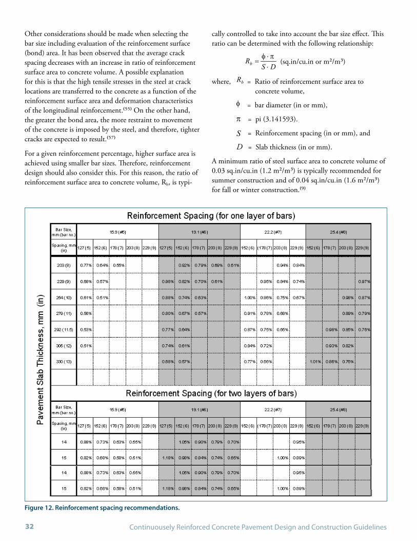
Continuousely Reinforced Concrete Pavement Design and Construction Guidelines32
Figure 12. Reinforcement spacing recommendations.
Other considerations should be made when selecting the bar size including evaluation of the reinforcement surface (bond) area. It has been observed that the average crack spacing decreases with an increase in ratio of reinforcement surface area to concrete volume. A possible explanation for this is that the high tensile stresses in the steel at crack locations are transferred to the concrete as a function of the reinforcement surface area and deformation characteristics of the longitudinal reinforcement.(55) On the other hand, the greater the bond area, the more restraint to movement of the concrete is imposed by the steel, and therefore, tighter cracks are expected to result.(57)
For a given reinforcement percentage, higher surface area is achieved using smaller bar sizes. Therefore, reinforcement design should also consider this. For this reason, the ratio of reinforcement surface area to concrete volume, Rb, is typi-
cally controlled to take into account the bar size effect. This ratio can be determined with the following relationship:
DSRb ⋅
⋅=
(sq.in/cu.in or m2/m3)
where, Rb = Ratio of reinforcement surface area to concrete volume,
= bar diameter (in or mm),
= pi (3.141593).
1004
2
⋅⋅⋅⋅
=spD
S pf = Reinforcement spacing (in or mm), and
D = Slab thickness (in or mm).
A minimum ratio of steel surface area to concrete volume of 0.03 sq.in/cu.in (1.2 m2/m3) is typically recommended for summer construction and of 0.04 sq.in/cu.in (1.6 m2/m3) for fall or winter construction.(9)

May 2009 - DRAFT LAYOUT 33
Vertical Position of ReinforcementThere are two primary considerations that should be made when selecting the vertical position of the longitudinal reinforcing steel.
On one hand, drying shrinkage and temperature fluc-tuations are typically more pronounced at the pavement surface, and can result in wider cracks at this location. It is believed that by positioning the reinforcement closer to the surface, narrower crack widths and higher load transfer efficiency can be achieved.
On the other hand, keeping the reinforcement closer to the surface increases the probability of exposure to chlorides from deicing salts, which may lead to corrosion. Future diamond grinding of the pavement surface would further reduce the distance of the reinforcement from the surface. Given these two considerations, it is common to position the reinforcement between one-third and one-half the slab thickness measured from the pavement surface.
To provide sufficient concrete cover, it is typically recom-mended to specify a reinforcement depth of at least twice the maximum aggregate size. Illinois DOT requires a mini-mum reinforcement depth of 3.5 inches (8.9 centimeters) from the pavement surface to the top of the longitudinal reinforcement to minimize the possibility of corrosion and to accommodate variations in construction procedures.
It is also recommended that the maximum reinforcement depth be no more than half the slab thickness measured from the surface. As illustrated in Figure 13, placement of reinforcement in two layers has also been used. This is implemented in the TxDOT specifications for pavements thicker than 13 in (330 mm ). The TxDOT standard CRCP(2)-03 in Appendix A shows a detail for placement of reinforcement in two layers.
Figure 13. Two-layered steel reinforcement mat.
It is believed that placement of the required reinforce-ment in this way not only helps to maintain the optimum reinforcement bond area to concrete volume ratio, but also ensures proper spacing while at the same time allowing reinforcement to be positioned closer to the CRCP surface where shrinkage strains tend to produce larger crack widths.
Based on long-term field testing in Illinois and on other projects in Belgium and elsewhere, the depth of reinforce-ment was a major effect on crack width. The higher the position of the reinforcement, the tighter the transverse cracks. Illinois sections with mid-depth steel had much more full depth repair than those with reinforcement above mid-depth over a 20 year period. Illinois recommends a 3.5 in (89 mm) covering over the reinforcement. The highly successful CRCP pavements in Belgium also place reinforce-ment above mid-depth.
Lap SplicesAdequate design of the reinforcement lap splices is neces-sary to maintain reinforcement continuity. Forces induced in the reinforcement by thermal and shrinkage movements are transferred through the lapped splice from one bar to the other by the surrounding concrete bonded to both bars. A minimum lap length of the splices is therefore necessary to ensure sufficient load transfer. Inadequate design and/or construction of the lap splices can result in failure of the reinforcement and poor CRCP performance, ultimately requiring expensive repairs.(58) Typical lap patterns are shown in Figure 14 and also in Figure 68 of Appendix A.
The effectiveness of the splice relies on achieving sufficient bond development length between the concrete and the reinforcement. Special consideration should be given to ensure that the concrete achieves adequate bond strength during the critical early-age period. This is particularly important during cold weather construction when the con-crete gains strength at a lower rate.
Guidelines on splicing length among the different States vary from 25 to 33 bar diameters.(32) Some State specifica-tions require the use of a fixed length of lap splicing varying between 16 and 20 in (406 and 508 mm). An experimental study looking at the bond development length for CRCP reported that lap splices of 33 bar diameters provide good performance, and may be the basis for the larger splice length specified.(59)
FHWA Technical Advisory T 5080.14 recommends a minimum splice length of 25 bar diameters if the splicing is performed in a staggered or skewed pattern. For a staggered

Continuousely Reinforced Concrete Pavement Design and Construction Guidelines34
splice pattern, no more than one third of the bars should terminate in the same transverse plane. In addition, the minimum distance between staggers should be 4 ft (1.2 m).
For the skewed splice pattern, the skew angle should be at least 30 degrees from perpendicular to centerline. In prac-tice, an approximate skew configuration may be achieved by skewing the reinforcement by half the pavement width (Figure 14). In any case, it is recommended that a minimum lap splicing of no less than 16 in (406 mm) be provided.
Corrosion ProtectionSome states require epoxy-coated rebar in CRCP to prevent corrosion of the reinforcement, especially in urban areas where maintenance and rehabilitation activities are strongly discouraged. This step may also be justified in environments with high exposure to chlorides from deicing salts, especially where corrosion has been previously identified as a problem.
The use of solid stainless steel, stainless steel clad, and other proprietary reinforcement non corrosive materials, such as Glass Fiber Reinforced Polymer (GFRP), should be consid-ered in areas with high chloride, with heavy deicer applica-
Figure 14. Typical layout pattern with laps skewed across pavement.
Pavement edge
Pavement edge Longitudinal bars spacing
Pav
emen
t wid
th
One half the pavement width
Not to scale
Transverse bars
1
1 Make sure sawed joints are not over a steel bar.
1
1
tions, or where long life (50 years or greater) is desired. Cor-rosion of reinforcing steel in CRCP has been rarely reported though, and is usually attributed to inadequate reinforce-ment design resulting in wide transverse cracks.(60)
The designer should strive to provide sufficient reinforce-ment to maintain narrow crack widths and sufficient reinforcement depth. These measures will help to minimize the probability of reinforcement exposure to chlorides from deicing salts. Additionally, increased steel percentages to account for potential corrosion may be also considered dur-ing design.
In the case where epoxy-coated bars are employed, the effect of the epoxy coating on the reinforcing steel bond develop-ment length should be accounted for. The FHWA Technical Advisory TA 5080.14 recommends an increase of 15 per-cent in the bond area when epoxy coated rebar is used.(56) Although, some studies have found no significant difference in cracking patterns between the use of uncoated and epoxy-coated reinforcement. It is believed that additional research is needed in order to better understand the effect of epoxy coatings on CRCP behavior and performance.

May 2009 - DRAFT LAYOUT 35
Transverse ReinforcementTransverse reinforcement in CRCP serves several purposes, including:
1. To function as tiebars across longitudinal joints (if continuous).
2. To keep uncontrolled longitudinal cracks that may form held tight (which may occur due to shallow saw cuts, late sawing, differential settlement, or heave).
3. To support longitudinal steel in place (ensuring proper spacing and depth according to specifications if mechan-ical placement of the longitudinal steel is not used).
Illinois and Texas, which both predominantly use CRCP, both use transverse reinforcement – Illinois in urban areas and Texas in all areas. For pavements wider than 7m (24 ft), it is recommended to use continuous transverse reinforce-ment with an expansion joint adjacent to concrete traffic barriers.
Size and SpacingAs with longitudinal reinforcement, the design of transverse reinforcement consists of determining the required amount of reinforcement per cross sectional area of concrete, and then selecting a corresponding bar size and spacing configu-ration. The reinforcement design is based on equilibrium of base layer restraint and concrete contraction forces. The required percentage of transverse reinforcement can be obtained with the following relationship:
100
2⋅
⋅⋅=
s
sct f
FWp
where, tp = Percentage of transverse reinforcement (%),
c = Unit weight of concrete (lb/cu.in or kN/m3),
sW = Total pavement width (in or m),
F = Coefficient of friction (unitless), and
sf = Working stress of steel (75% of yield strength) (psi or kPa).
Friction coefficients for different base materials are provided in Table 4.
Once the required percentage of transverse reinforcement is determined, a bar size is selected and the transverse steel spacing is obtained as follows:
Table 4. Friction coefficients for different base materials.(5)
Type of Material Beneath Slab Friction Factor (F)
Surface treatment 2.2
Lime stabilization 1.8
Asphalt stabilization 1.8
Cement stabilization 1.8
River gravel 1.5
Crushed stone 1.5
Sandstone 1.2
Natural subgrade 0.9
100
4
2
⋅⋅⋅⋅
=Dp
Yt
where, Y = Transverse steel spacing (in or mm),
= Bar diameter (in or mm), and
D = Slab thickness (in or mm).
Typical reinforcing recommended in the transverse direc-tion includes # 4 to # 6 (12.7 to 19.1 mm) Grade 60 (Grade 420) deformed bars. It is common for transverse reinforcement to be spaced from 12 in (0.3 m) to 36 in (0.9 m) apart.(2) It should be noted that following this design procedure is very conservative, as the steel stresses are great-est at the tied joints and in the center of the pavement and decrease to zero at the free edges.
Transverse reinforcement may serve a second purpose as tiebars if continuous across the joint. In this configuration, the transverse bars are typically extended half the required tiebar length across the longitudinal joint. For example, for a 24-ft (7.3-m) wide pavement, transverse reinforcement is designed for 12-ft (3.65-m) pavement widths and this rein-forcement is extended across the middle longitudinal joint to function as a tiebar.
Since transverse reinforcing bars are typically used to keep longitudinal reinforcement bars in place, they are com-monly specified to be positioned below the longitudinal reinforcement.
TiebarsTiebars are used along lane-to-lane or lane-to-shoulder longitudinal joints, when placed in separate passes, to keep these joints tight, and to ensure adequate load transfer. The required amount of tiebar reinforcement along longitudinal

Continuousely Reinforced Concrete Pavement Design and Construction Guidelines36
joints is determined in a similar way as for transverse rein-forcement. However, in this case, the length of pavement for analysis corresponds to the distance from the tied joint to the closest free edge.
A shorter distance to the free edge will result in a lesser amount of reinforcement required to hold the longitudinal joint together. The following equations are used to deter-mine the percentage of tiebar reinforcement and tiebar length required:
100
'⋅
⋅⋅=
s
ct f
FWp
where, tp = Percentage of tiebar reinforcement (%),
c = Unit weight of concrete (lb/in3or kN/m3),
'W = Distance from tied joint to closest free edge (in or m),
F = Coefficient of friction, and
sf = Working stress of steel (75% of yield strength) (psi or kPa).
ab
s lf
ft +
⋅=
21
where, t = Tiebar length (in or mm),
= Bar diameter (in or mm),
sf = Working stress of steel (75% of yield strength) (psi or MPa), and
bf = Allowable bond stress (typically assumed to be 350 psi (2.44 MPa)),
al = Additional length for misalignment (3 in or 75 mm).
For economy and simplicity, tiebar length is often selected based on available standard manufactured lengths. Typical tiebars consist of Grade 40 or 60 (Grade 300 or 420) steel. Common standard manufactured tiebar lengths include 24, 30, 36, 42, and 48 in (0.61, 0.76, 0.91, 1.07, and 1.22 m). A maximum tiebar spacing of 48 inches (1.22 m) is recommended.
For wide pavements, it is generally more economical to provide an untied longitudinal joint rather than extending transverse bars along the total pavement width. Caltrans,
for example, requires at least two lanes but no more than 50 ft (15.2 m) between untied joints. An untied joint may alleviate excessive transverse concrete stresses that could lead to potential longitudinal random cracking. It is recom-mended that untied joints be located far from the pavement edge to avoid lane separation. Expansion joints adjacent to concrete traffic barriers without providing load transfer are commonly used to prevent the formation of uncontrolled longitudinal cracks in these situations.
For longitudinal construction joints, tiebars are often inserted along the edge while concrete is fresh. It should be emphasized though that bending of the tiebar should be discouraged since it may result in cracking of the steel, and based on experience, there have been several instances where the tiebars have not been unbent prior to placing the adja-cent concrete. In addition, when tiebars are epoxy coated, bending may result in damage of the epoxy, giving place to corrosion.
Some State DOTs require the use of multiple-piece tiebars to prevent problems associated with bending bars. This type of tiebar comes in two pieces that are threaded together. Female couplers are inserted along the longitudinal joint in the fresh concrete before paving the adjacent section; the threaded piece is later screwed in place to form a complete tiebar. With the use of these mechanisms, bending of the tiebar is avoided. Multiple-piece tiebars should conform to ASTM A 615 specifications, and the coupler should be required to develop a failure force of 1.25 to 1.5 times the yield strength of the steel.(2) Another option is to drill and epoxy tiebars and require a pull-out test as per ASTM E 488. Regardless of the tiebar type and method of placement, it is important to ensure that tiebars are securely anchored so that they provide the pull-out resistance required by design.
JointsCRCP does not require transverse joints in the same way that jointed concrete pavements do. However, joints in CRCP are still necessary. Joints in the longitudinal direction are used between traffic lanes, and between traffic lanes and tied concrete shoulders. Transverse joints are also neces-sary for construction purposes at the start and end of daily operations. Transition or terminal joints are also necessary for approaches to some types of structures and the transition to other pavement types. This section provides design details that should be considered when designing CRCP joints.

May 2009 - DRAFT LAYOUT 37
Longitudinal JointsThe use of longitudinal joints is recommended for pave-ments wider than 15 ft (4.6 m). Joints are typically located in between lanes and between a lane and a concrete tied shoulder. Tiebars or transverse reinforcement should be pro-vided along longitudinal joints to prevent separation, and to maintain adequate joint transfer efficiency. Two types of longitudinal joints are commonly used in CRCP: construc-tion and contraction joints.
Better practices for concrete pavement joints can be found in the IMCP manual and elsewhere. However, some typical sections of joints that have been used on CRCP pavements are given herein.
A longitudinal construction joint is illustrated in Figure 15, and is specified when more than one pass is necessary to pave the total pavement width. In the past, it was recom-mended that trapezoidal or half-round keyways were formed
Figure 15. Longitudinal construction joint with multiple piece tiebars.
Figure 16. Longitudinal contraction (hinged) joint with transverse bars.
along the longitudinal construction joints to increase its load transfer efficiency. However, some key joints have failed in shear resulting in spalling along the joint. In addition, the area along the keyway may be more susceptible to concrete consolidation problems. It is therefore recommended that tied butt joints be used instead.
Longitudinal contraction (hinged) joints, as illustrated in Figure 16, ensure that longitudinal cracking on wide pave-ments occur along a fixed (weakened) plane. Longitudinal joints are created by performing a sawcut at the specified joint location to relieve the stresses generated in the trans-verse direction of the concrete due to volumetric changes.
Along these longitudinal joints, either transverse reinforce-ment or tiebars should be used to tie the adjacent slabs together and to maintain adequate load transfer efficiency. Reinforcement design should follow recommendations provided in Section 4.5.
Transverse bars
Longitudinal bars
Tiebars-may be in same horizontalplane as transverse bars
2L
Tie bar length
T
2T
50 mm 50 mm
Joint sealingmaterial
MultiplePiece tiebars
-
T
Joint sealingmaterial
Longitudinal bars
T
21
2±T
Transverse bar
3T
Saw cut

Continuousely Reinforced Concrete Pavement Design and Construction Guidelines38
Transverse Construction JointsTransverse construction joints are formed at the start and end of paving operations, or whenever paving operations are halted long enough to form a cold joint. Proper design and construction of transverse construction joints is essential to maintain continuity of the CRCP.
Figure 17 shows a transverse construction joint detail. A minimum of 1.0% of longitudinal reinforcement should be provided at transverse construction joints by placing addi-tional reinforcement bars along the joint. Deformed bars 72-in (1.8-m) long and with the same size and grade of the longitudinal reinforcement are typically used to reinforce the transverse construction joint. These tiebars are placed between every other longitudinal bar to provide the required additional reinforcement.
The additional reinforcement is provided to resist the increased shear and bending stresses at the joint, and to pro-vide additional bond area required to accommodate stresses generated during the first few days after construction, before the concrete gains sufficient strength.
In addition, lap splices that fall within 3 ft (0.9 m) behind the construction joint, or lap splices that fall within 8 ft (2.4 m) ahead of the construction joint (in the direction of paving), should be additionally strengthened. It is recom-mended that the lap either be made double the normal length, or else additional deformed bars 6 ft (1.8 m) long of the same size as the longitudinal reinforcement be spliced in symmetrically with the lap.(2)
This is especially important for transverse construction joints in order to produce high-quality concrete on both ends of the joint. Many transverse construction joints have performed poorly due to inadequate concrete consolidation.
Figure 17. Transverse construction joint.
Joint sealingmaterial
Transverse bars
Regular longitudinalbars (continuous)
Additional steel bars may bein same horizontal plane asthe longitudinal bars
T
2L
21
2±T
T
Transition or Terminal JointsTransition or terminal joints are provided in CRCP to accommodate pavement growth that, if uncontrolled, may close the expansion joint in the approach to structures and induce damage to the adjacent structure. Pavement growth is typically a result of expansion changes in the concrete pavement coupled with intrusion of incompressibles at the cracks. Areas with high precipitation have been found to experience this more frequently since precipitation produces a higher accumulation of incompressibles at the cracks.
Two types of joints are commonly used to prevent excessive CRCP movement: terminal end anchors and wide-flange beams. Terminal end anchors attempt to restrain movement, while wide-flange beams are effective in accommodating movement.
Terminal End Anchor Joints
End anchors were originally developed to restraint move-ment in jointed pavements. In fact, their use would be more justified on jointed pavements since on this type of pavement there is an increased chance of intrusion of incompressibles at the joints with the consequent pavement growth. The practice of using anchor lugs was carried over from jointed pavements to CRCP.
End anchors are provided by a series of concrete lugs underneath the pavement that anchor to the subgrade and attempt to restrain CRCP movement. The lug depth depends on the soil type and frost conditions. Soil types with low stiffness and thus low resistance to movement may compromise the effectiveness of the end anchors. In such situations, end anchor lugs should not be used. A design standard for terminal end anchors is provided in Figure 65 of Appendix A.

May 2009 - DRAFT LAYOUT 39
Regardless of the CRCP length, its central portion remains fully restrained by the underlying base and no change in length is experienced with exception of the last few hundred feet [typically 300 to 400 ft (90 to 120 m)] at the ends.
Wide-Flange Beam Joints
Wide-flange beam joints are increasing in popularity as a means to control CRCP end movements.(8) Wide-flange beam joints provide room for CRCP expansion and provide a means to maintain joint load transfer efficiency. Figure 18 shows a typical design detail for a wide-flange beam joint. This joint is typically formed by casting a 10-in (250-mm) thick by 10-ft (3-m) long reinforced sleeper slab used to support the ends of the abutting pavements.
A wide-flange beam is embedded 5 to 6 in (127 to 152 mm) into the sleeper slab so that the top flange is flush with the CRC pavement surface. Compressible joint material such as polystyrene is provided on the side of the beam web,
Figure 18. Wide-flange beam joint detail.
30º100
mm
38 mm
Beam
Continuously reinforced concrete pavement
Heavily greasedsurface
250 mm
25 mm expansion joint material
(Styrofoam or equivalent)
3.0 m
Bond breaker
No. 5 bars, 1.15 m long @ 150 mm o.c.
No. 4 bars @ 300 mm o.c.
150 mm
<1.5 m
25 mm joint seal
6 mm joint seal
expansion joint
dowelsTaper
NOTES: * Weld shear connectors to flange and web of beam.
No. 5 bars @ 200 mm o.c.
11 mm beam stiffener plates welded at 1.8 m o.c.19 mm dia. X 200 mm studs at 460 mm o.c.*
Approach Slab
30º100
mm
38 mm
Detail
adjacent to the CRCP, to allow for expansion. In addition, a bond breaker is used on top of the sleeper slab to allow the pavement ends to move freely. It is important to provide adequate support for the sleeper slab or it may sink at one end.
It is recommended that corrosion protection be provided for the wide-flange beam, commonly using a corrosion inhibitor. To provide room for additional expansion, one or more slabs with doweled expansion joints are typically con-structed between the CRCP transition joint and the bridge approach slab.
Some wide-flange beam joint premature failures have been reported in the past. The type of failure observed was separa-tion of the top flange from the beam web. Because of this, it is now recommended to weld stud connectors to the top flange of the beam to prevent this type of failure. Recom-mended wide-flange beam sizes for various pavement thick-nesses are provided in Table 5.
Table 5. Wide-flange (WF) beam (weight and dimensions) (56)
Slab Thickness in (mm)
Embedment in “Sleeper” slab
Size x Weight in x lb/ft (mm x kg/m)
Flange Width in (mm)
Flange Thickness in (mm)
Web Thickness in (mm)
8 (203) 6 (152) 14 x 61 (356 x 91) 10 (254) 5/8 (16) 3/8 (9.5)
9 (229) 5 (127)
254 (10) 6 (152) 16 x 58(406 x 86) 8.5 (216) 5/8 (16) 7/16 (11)
10 (279) 5 (127)

Continuousely Reinforced Concrete Pavement Design and Construction Guidelines40
A recent FHWA study looked at the performance of existing CRCP sections in several States. In this study, fewer dis-tresses such as spalling and faulting of the transition joint were observed on wide-flange beam joints than on terminal anchors. This may attributed in part to the younger ages of the wide-flange beams.(8)
Worth noting is that success has been achieved in provid-ing continuity between the CRCP reinforcement and that in continuous span bridge structures.(62, 63) This is accom-plished by tying the CRCP to both ends of the bridge, with some jointing modifications. It is believed that by success-fully tying the CRCP to the bridge structure, the designer can provide for a smooth transition between these elements. One successful implementation of this technique was recently accomplished on Westlink M7 in Sydney, Australia.(63)
Other Design DetailsThe following paragraphs provide information on design details for crossovers, shoulders, ramps, and auxiliary lanes.
CrossoversCrossovers are often used during construction to provide access to thru traffic. When crossovers are needed, it is recommended to pave the crossover in anticipation of the mainline paving requirement. Leaving gaps in the CRCP to provide room for crossovers is not recommended. When these gaps are paved, they are subjected to excessive move-ment exerted by the CRCP on both ends due to cyclic temperature changes. During the first days after plac-ing, the leave-out concrete will not have reached its full strength, and will be more susceptible to slippage of the reinforcement.
Figure 19. Layout of reinforcement in leave-out section.(58)
Pavement edge Leave-out symmetrical about CL Construction joint
2.1 m min. 0.90 m min.
3.0 m min.Pavement edge
NOTE: Transverse steel not shown.Longitudinal bars at normal spacing
50% additional longitudinal bars in Leave-out
C

May 2009 - DRAFT LAYOUT 41
Paving these sections ahead of the mainline paving prevents reinforcement slippage since it is less unlikely that the short length of the paved crossover will exert excessive force on the fresh CRCP. It is recommended that special attention be given to crossovers when planning the paving schedule in order to minimize the need for leave-outs. Some States such as South Dakota include language in their specifications to discourage leave-out gaps.
An option worth considering is the use of a fast-track (high early strength) concrete in areas where a leave in/leave out would otherwise been used. Where this has been tried wet mat curing has been provided for 24 hours. This method would require prior coordination for the delivery of high-early strength concrete in a timely manner so that all con-crete within the crossover is high-early strength.
When leaving a gap in the CRCP cannot be avoided, a minimum of 50 percent additional reinforcement should be required in the leave-out and across the construction joints on both ends of the leave-out. The additional reinforcement should be evenly distributed between every other regular reinforcement bar. Both additional and regular reinforce-ment bars should extend into the leave-out no less than 7 ft (2.1 m) and should be embedded no less than 3 ft (0.9 m) into the pavement ends adjacent to the leave-out. Splices in the leave-out area should follow the same requirements as those followed at a construction joint.
Shoulders Shoulder types that are commonly used with CRCP include concrete and asphalt shoulders. While asphalt shoulders may require lower initial construction costs than concrete shoulders, the longitudinal joint between the CRCP and asphalt shoulder often requires significant maintenance activities during the life of the pavement. On the other hand, concrete tied shoulders provide enhanced lateral structural support resulting in a reduction in both pave-ment deflection and stress under traffic loading, leading to improved performance.
In order to provide increased structural support, concrete shoulders should be properly tied to the mainline pavement. While tied concrete shoulders paved in a second pass after the mainline pavement provide good lateral support, addi-tional benefits are obtained from shoulders paved mono-lithically since a significant improvement in load transfer is achieved by aggregate interlock at the longitudinal joint with the mainline pavement.
Concrete shoulders for CRCP may be designed as either CRCP or JCP. Roller compacted concrete (RCC) has also been used. CRCP shoulders can provide a uniform pave-ment section that can later be fully utilized when additional lanes are required. Jointed concrete shoulders (with no rein-forcement) may provide savings in comparison to CRCP shoulders in terms of initial construction cost, although future maintenance of the CRCP to JCP joint may be required. If JCP shoulders are selected, it is recommended to use short joint spacings (< 15 ft. (5m)) on the shoulder in order to minimize joint movement that could cause addi-tional cracking in the CRCP mainline pavement.
Other factors that require consideration when selecting the shoulder type include the effect the shoulder will have on drainage as well as the effect that the environment will have on shoulder performance.
As an alternative to shoulders, experience has shown that by extending the outer concrete lane by at least 1 ft (0.3 m) into the shoulder to create a “widened lane,” this can signifi-cantly reduce edge deflections. The use of a widened lane can provide either additional pavement life or an opportu-nity to decrease the CRCP thickness. With these consid-erations, some States have opted to use widened lanes and asphalt shoulders. While this combination may not be as beneficial as monolithic tied concrete shoulders, it provides a trade off between initial construction costs and enhanced performance.
Ramps and Auxiliary LanesSelection of pavement type for auxiliary lanes between accel-eration/deceleration lanes should take into account similar considerations as for shoulders in the previous section. In general, CRCP with the same characteristics as the mainline paving is also recommended for auxiliary lanes.
Pavement ramps, also termed acceleration/deceleration lanes, can be either CRCP or jointed pavement. It is typi-cally recommended that ramps be tied to the mainline pav-ing with the use of tiebars along the longitudinal joint, or by extending the transverse reinforcement from the mainline paving. Reinforcement design along the ramp to lane joint should follow the same guidelines as those provided for conventional longitudinal joints.
Performance of the longitudinal joint between the ramp and mainline paving will also depend on the differential movement between these two elements. If the ramp is constructed with jointed pavement, it is recommended to

Continuousely Reinforced Concrete Pavement Design and Construction Guidelines42
provide a short joint spacing similar to jointed concrete shoulders to minimize movement and potential cracking of the CRCP. Furthermore, it is recommended to use jointed concrete pavement on the ramp if the distance between the CRCP end and the gore section of the ramp is less than
Figure 20. Recommended layouts for ramp connections.
Figure 21. Jointing details for ramp connections.
Area of confluence Variable length
RampBegin taper ( See Detail E )
Thru Lane No. 1Thru Lane No. 2Thru Lane No. 3
ENTRANCE RAMP
EXIT RAMP
Thru Lane No. 3Thru Lane No. 2Thru Lane No. 1
Ramp
Area of confluence Variable length
Begin taper ( See Detail E )
Connection with asphalt or jointed pavement
(see joint detail)
Connection with asphalt or jointed pavement
(see joint detail)
200 ft (60 m). This is to prevent excessive movement of the CRCP with respect to the ramp. Recommended layouts for ramp connections and jointing details are provided in Figure 20 and Figure 21.
Edge of Lane No.1
0.6 m
Edge of Lane No.1
0.6 m
Longitudinal BarsTransverse Bars
Tie Bars
3.65 m
T
Ramp Ramp
DETAIL E ALTERNATE ELongitudinal construction joint
C.R.C.P Flexible Pavement
T
50 mm
3.0 m
Transverse construction joint with asphalt pavement
T
3.0 m
Doweled Expansion Joints
Transverse construction joint with jointed pavement
C.R.C.P
50 mm
Flexible Pavement

May 2009 - DRAFT LAYOUT 43
Figure 22. Design detail for CRCP intersection.(67)
IntersectionsIntersections present a unique challenge for CRCP design as maintaining continuity of reinforcement in both direc-tions through the intersection may be required if two CRCP pavements are intersecting. A recent TxDOT research report documents best practices for design and construction of CRCP in transition areas, including intersections.(67) As shown in Figure 22, the report provides design details used by TxDOT for maintaining reinforcement continuity in both directions through an intersection.
Note that the longitudinal reinforcement for the pavement in one direction provides the transverse reinforcement for the pavement in the other direction and vice versa. The report also provides design details for isolating intersecting CRC pavements when maintaining reinforcement continu-ity in only one direction is necessary, as well as intersec-tion details for CRC pavements intersecting non-CRC pavements.


CHAPTER 6
CRCP CONSTRUCTION OVERVIEW

Continuousely Reinforced Concrete Pavement Design and Construction Guidelines46

May 2009 - DRAFT LAYOUT 47
To assure the superior performance that is commonly associ-ated with CRCP, construction plans and specifications that properly address critical details are essential. Uniformity and consistency of concrete placement and reinforcement location along the project are also necessary. In addition, climatic conditions encountered during actual placement of the pavement can have a significant effect on future per-formance. This section of the guide provides information on key aspects of the construction process that is critical in achieving successful CRCP performance.
The key structural performance indicator of CRCP is the width of transverse cracks. If the transverse cracks can be held tightly together over the intended design life, the likelihood of good CRCP performance is greatly enhanced. When cracks are wide, the CRCP loses the ability to transfer shear stresses from heavy wheel loads. This loss of load transfer will quickly lead to the development of punchouts, the primary structural failure in CRCP. As illustrated in Figure 23, punchouts lead a loss of smoothness and require full-depth repairs.
Crack width depends on several design and construction factors. These include depth of reinforcement, proper lap lengths on reinforcement bars, staggering of laps, concrete shrinkage, concrete thermal coefficient of expansion, the effects of moisture on concrete expansion and contraction, concrete consolidation, set temperature of the CRC slab (climate conditions at time of construction), and friction between the base and CRC slab. (69,70,71)
Many CRCP performance problems have been related to inconsistent or inappropriate construction practices that do not meet stated design requirements. For example, CRCP has exhibited distresses due to inadequate consolidation of the concrete at construction joints, inadequate reinforce-ment laps, delamination due to steel too close to the surface, and loss of ride quality due to differential subgrade settle-ment along the project, especially in areas where embank-ments are placed on heavy existing clays.
Construction quality must be consistent throughout the project. Quality construction results in both uniformity (in subgrade, base, slab, and reinforcement) and uniformly spacing and width of transverse cracks that maintain load transfer over the design life).
Contracting for InnovationAs knowledge and understanding of CRCP construction and performance increases, innovative contracting proce-dures may need to be implemented in order to allow the contractor more options for building a high quality pave-ment. For example, quality assurance testing will allow for improvement of the quality and the performance of the product.
Some States now require contractors to perform quality assurance testing with certified equipment and operators, with only random checks performed by the State. Currently, these efforts are focused on ride quality, but could also include following:
Deflection testing to evaluate variability and structural •behavior;
Ground penetrating radar to check steel placement, layer •thickness, and moisture related issues;
Visual Condition Survey to document the as-built crack •spacing and crack widths;
Skid testing to document as-built frictional characteristics; •and
Core strengths to document as-built strength and •variability.
Figure 23. Edge punchout in CRCP.


CHAPTER 7
CRCP SUPPORT CONSTRUCTION

Continuousely Reinforced Concrete Pavement Design and Construction Guidelines50

May 2009 - DRAFT LAYOUT 51
Base LayersThe base course directly beneath a CRCP is a very critical component. The base course must provide the following:
Smooth construction platform on which to construct a •smooth CRCP;
Permanent support to the CRCP over its design life;•
Non-deforming and smooth surface for accurate rein-•forcement placement and placement of a uniform CRCP slab thickness; and
Sufficient friction with the CRCP slab to help form •adequate crack spacing.
Several types of bases have been used successfully, includ-ing unbound aggregate, cement-treated and lean concrete, asphalt-stabilized, and combinations of the above. Each of these base courses must be designed and constructed properly to avoid contributing to problems in CRCP performance.
It is also common to place a subbase layer, either an unbound granular material or treated subgrade layer, between the base and the subgrade. This subbase layer is extremely important when the subgrade is wet and soft, as it can reduce erosion of the top of the subgrade and provide a construction platform for base construction.
The width of the base course is important during construc-tion. Ideally, it should extend beyond the CRCP slab edge by at least 3 ft (0.9 m) to provide increased edge support and to provide a stable track-line for paving operations. It may be necessary to widen the base further to accommodate some newer paving equipment.
Base thicknesses in the range of 4 to 8 in (100 to 200 mm) are common for highways. Subbase thicknesses are often 6 to 12 in (150 to 300 mm) or greater.
Asphalt-Stabilized BaseField studies have shown that the addition of asphalt to granular materials to produce a non-erodible stabilized mix-ture for base construction can improve CRCP performance.(73) An example of an asphalt-stabilized base is illustrated in Figure 24. Proper (as-designed) asphalt content, density, and other mix quality parameters must be achieved during con-struction. The key benefits include minimizing moisture-related loss of support, providing a smooth construction platform for steel placement and improved ride quality, and supplying an adequate amount of friction with the CRCP to provide proper crack spacing, and to provide stress relief during curling and warping cycles.
Stripping of asphalt binders from aggregates in these bases has been a concern. Stripping is a direct result of moisture
Figure 24. Asphalt-stabilized base. (photo courtesy of Zachry Constrution)

Continuousely Reinforced Concrete Pavement Design and Construction Guidelines52
in the pavement system that brakes down the bond between the aggregate and asphalt binder. Consequently, the use of asphalt stabilized bases in areas with high water tables should be designed with proper additives, and its use, if any, should be used with caution.
Cement-Treated BaseA cement-treated base consists of crushed stone base commonly blended through a pugmill with an optimized quantity of cement (typically 5 percent) to achieve a 7 day compressive strength of 500 psi (3.5 MPa) and water at 1 to 2 percent below the optimum moisture content. A strong and non-erodible cement-treated base can be very effective in improving CRCP performance and has been successful in areas with high water tables. Some erosion and deteriora-tion of cement stabilized base courses have occurred in the past, creating loss of support problems for CRCP. However, this can be prevented through proper materials selection and construction, particularly achieving adequate density and consistency of material.
For cement-treated base, the time between mixing, place-ment, and initial compaction should not exceed 1 hour. Complete bonding between a cement-treated base and concrete slab is not recommended due to potential of reflec-tion cracking and the increase in the effective CRCP slab thickness, which results in the need to increase the amount of steel reinforcement.
An interlayer of some type should be used between the slab and the base to serve as a stress relief layer. Most often, a 1 to 2 in (25 to 50 mm) layer of rich, dense-graded HMA is placed on top of the cement-treated base layer to minimize erosion potential while providing stress relief for curling, warping, expansion and contraction.
While not necessarily for CRCP until recently, contractors in Germany have been using a 0.2 in (5 mm) thick non-woven geotextile as a stress relief layer between concrete pavements and cement stabilized bases. Figure 25 shows the system used for placing the geotextile. The fabric is fastened to the subgrade or base layer with a washer and nail as shown in Figure 26, to secure it during construction. Cores taken in a pavement built in 1981, as shown in Figure 27, noted no deterioration in the geotextile or cement-treated base.
Cement-treated bases should not be placed under freezing or near freezing conditions. It is recommended that the material be placed and cured when ambient air temperatures are greater than 40°F (4°C) (measured in a shaded area) until adequate strength is reached. Cement-treated bases can
Figure 25. Placing geotextile interlayer in Germany.
Figure 26. Fastener for geotextile interlayer.
Figure 27. Core taken showing pavement with geotextile interlayer.
be cured by covering with polyethylene sheeting for 3 to 5 days or spraying a fine water mist several times a day after placement. At the end of each day’s construction, a straight transverse construction joint should be formed by cutting back into the completed base to form a vertical face.

May 2009 - DRAFT LAYOUT 53
Lean Concrete BaseLean concrete, sometimes known as “econocrete”, is made of aggregates that have been plant-mixed with a sufficient quantity of cement to provide a strong and non-erodible base. Lean concrete has been used as a base course for many CRCP. It can provide a smooth uniform surface as a con-struction platform for steel placement and paving. It can be placed using the same equipment that will pave the concrete surface. Lean concrete bases should be cured using white-pigmented curing compound and be left untextured to prevent bonding to the CRCP.
Field studies have shown that a lean concrete base of adequate strength will reduce erosion of the base and loss of support.(75,106,107,108) Some agencies specify sawcut weakened plane joints once the lean concrete base has set to prevent large cracks from forming and reflecting into the CRCP surface. Other agencies successfully placing a layer of asphalt-stabilized base or HMA (1 to 2 inches or 25 to 50 mm thick) on top of the lean concrete base layer to mini-mize erosion, provide stress relief, and provide a moisture barrier, similar to that recommended for a cement-treated base.
Figure 28. Trimming and compacting granular base.
Dense-Graded Granular Base and SubbaseDense-graded unbound granular materials with low plastic-ity have been used successfully as a base and subbase for CRCP. To minimize consolidation and settlement problems, a relative density of 95 to 100 percent as determined by AASHTO T 180 (Modified Proctor) is necessary.
Care should also be exercised during construction and fine grading to avoid segregation and minimize loss of density and uniformity. Any of these conditions can result in loss of slab support and subsequent CRCP failures. Specialized equipment is often used to place the granular materials to a uniform depth without segregation, as shown in Figure 28.
It should be noted that some agencies have had significant problems with pumping and loss of support with unbound bases, even on strong dry subgrades. Use of an untreated aggregate base under CRCP will result in much longer crack spacing for the same reinforcement content. This may cause serious problems in crack spacing for the same crack deterioration and punchout development. This can be accommodated by increasing the reinforcement content. The MEPDG provides recommended friction values for unbound base courses calibrated from field conditions.

Continuousely Reinforced Concrete Pavement Design and Construction Guidelines54
Because CRCP is normally used for heavily trafficked highways, most agencies utilize a stabilized base to minimize erosion and loss of support, and instead opt for a granular subbase. This combination has helped facilitate construction and provide the uniform foundation needed for long term and high quality performance.
Open-Graded Permeable BaseAn open-graded permeable base is a drainable layer with a typical laboratory permeability value of 1000 ft/day (300 m/day) or greater. Permeable asphalt-treated and cement-treated bases have seen limited use as open-graded drainage layers for CRCP.
The primary function of this layer is to collect water infil-trating the pavement and move it to edge drains within an acceptable time frame. However, the permeability of the base should always be balanced with stability. Stabil-ity is more critical than permeability in CRCP foundation systems.
The main problem with open-graded bases for CRCP is that concrete mortar often infiltrates the base resulting in additional bonding between the slab and base/subbase, which increases the effective CRCP slab thickness, thereby reducing the steel as a percentage of the slab cross section. These effects can change the crack spacing and lead to per-formance problems.
In addition, due to the relative “flexibility” of CRCP, the unbound layer just beneath the open-graded layer may pump into and infiltrate the permeable layer causing local-ized settlements, which has occurred with lime treated sub-grades on some projects. For these reasons, permeable bases are not generally recommended for CRCP, unless strong practical measures to prevent these problems are taken, such as the use of geotextiles.
Open-graded permeable bases were very popular in the late 1980s and early 1990s, but due to a number of failures from these mechanisms, many agencies now discourage their use. If deemed a necessary component, however, measures should be taken to reduce the target permeability to 100 ft/day (30 m/day) in order to improve stability.
Edge Drains and Impervious Moisture BarriersHeavy traffic combined with moisture variations in suscepti-ble materials often leads to erosion in the base and subgrade
or shrinkage and swelling that leads to premature concrete pavement failures, including CRCP. Infiltration of water into the CRCP structure can be controlled with proper cross slopes, maintaining a seal that prevents moisture changes in unbound pavement layers, and construction of an edge drainage system to transport water away from the pavement structure.
Edge drains work best in granular soils. However, in cohe-sive soils, which do not allow water to drain freely, edge drains can accentuate shrinking and swelling by causing the soils to be drier adjacent to the drains, which causes shrink-age. Alternatively, if drains become clogged and fill with water, adjacent soils will become saturated, which can lead to swelling.
To function properly in cohesive soils, edge drains should incorporate a moisture barrier to prevent wetting or drying of adjacent soils under the pavement. In addition, base and subbase layers must be free draining and extend over the edge drain. Care should be exercised during the construc-tion of these systems to:
Ensure that the as-designed gradation of the drainage •layer is obtained to preserve permeability,
Provide a system that allows access and can readily flush •out the system without causing any erosion,
Ensure that the drainage layer is placed and lightly com-•pacted without fracturing aggregate particles, which create additional fines, and
Avoid collapsing, breaking, and clogging of the pipes and •outlets.
It is also suggested to regularly conduct a video survey of the outlets and longitudinal pipes to ensure they can function.
An impervious moisture barrier can be used to effectively prevent both changes in surface grades and cracking along the pavement edges due to swelling soils. A vertical moisture barrier should be constructed as deep as the zone affected by seasonal moisture variations. Alternatively, a conservative minimum depth of 7 ft (2.1 m) can be used, as illustrated in Figure 29.
Before any drainage feature is added to a pavement sys-tem, an assessment should first be made of the cost of the system as it compares to the potential improvement to performance.
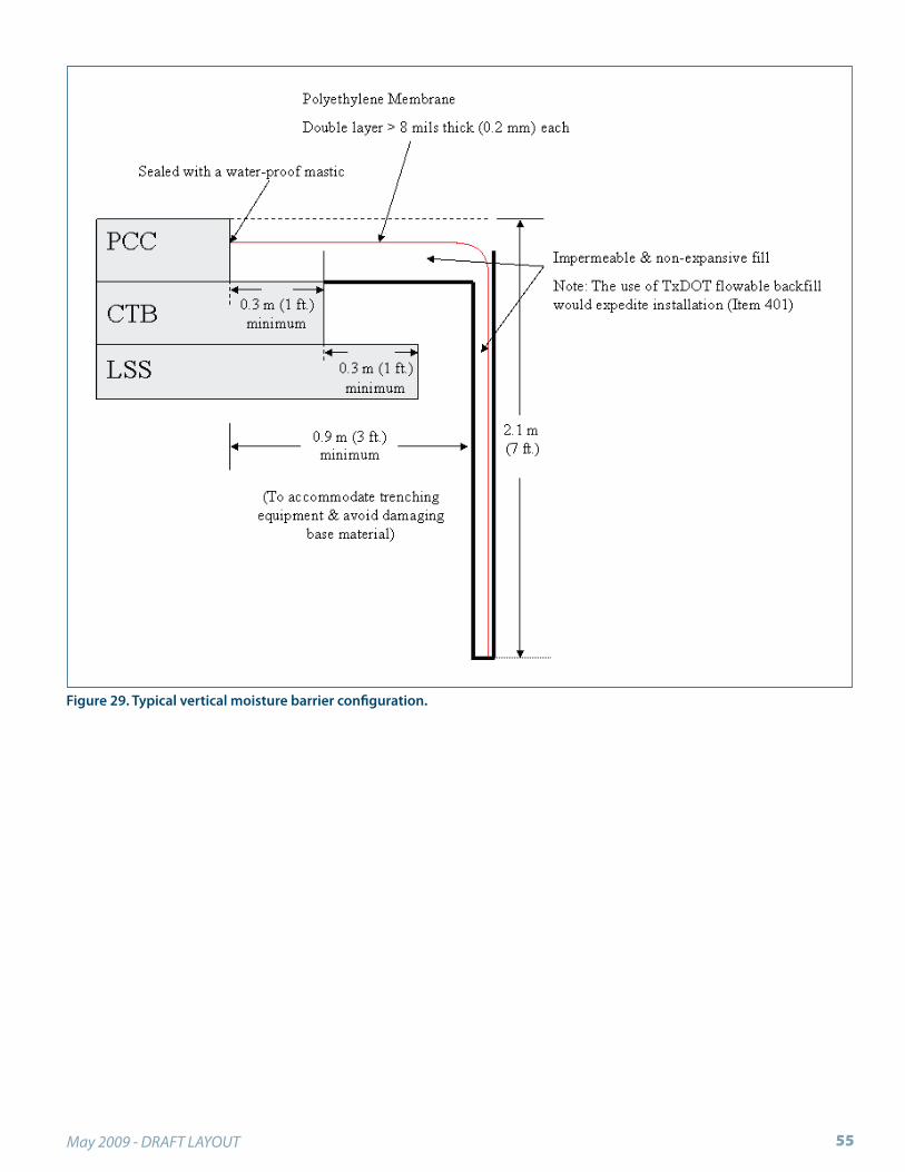
May 2009 - DRAFT LAYOUT 55
Figure 29. Typical vertical moisture barrier configuration.


CHAPTER 8
REINFORCEMENT

Continuousely Reinforced Concrete Pavement Design and Construction Guidelines58

May 2009 - DRAFT LAYOUT 59
Continuous steel reinforcement is the key feature that dis-tinguishes CRCP from jointed concrete pavement.
This section of the guide discusses the construction aspects of longitudinal steel reinforcing bars, transverse steel rein-forcing bars, and steel tiebars in CRCP. Steel requirements in construction joints, terminal treatments, and crossover treatments are discussed in Sections 8.4 and 9 of this guide.
Reinforcing steel should be placed as shown on plans; not-ing that:
As the thickness increases, both the longitudinal and •transverse steel requirements increase, and
As the pavement width increases, the transverse steel •requirements increase.
Characteristics of Reinforcing SteelOnly deformed steel bars should be used as reinforcement for CRCP. Reinforcing steel bars are characterized by size and yield strength (or grade). Standard ASTM reinforc-ing bars are required to be marked distinctively for size and minimum yield strength or grade. Figure 30 shows an example of the ASTM marking requirements for a #8, Grade 60 (#25, Grade 420 metric) bar. ASTM specifications require the bar size number (e.g., #8) to be rolled onto the surface of the bar as shown in the figure.
These specifications also allow a mill to choose to roll the grade number onto the bar, or roll on a single longitudinal rib or grade line to indicate Grade 60. Additional informa-tion about steel bar marking and identification is available in ASTM A615/A615M-96a, ASTM A706/A706M-96b, and ASTM A6/A6M-96.(76) The identification marks on bars delivered to the job site should be checked regularly against those shown on the plans. Certified Mill Tests and/or Bar Coating Reports should accompany shipments of reinforcing steel to the job site as shown in Figure 31.
A light brown coating of rust on reinforcing bars is consid-ered acceptable by industry. Although cited ASTM standard specifications do not consider the presence of mill scale as cause for rejection, a recent ACI paper found that bars with mill scale produced more corrosion compared to other bars investigated.(110)
Reinforcing steel should be stored on platforms off the soil to prevent damage and deterioration.
Figure 30. Example of the ASTM marking requirements for a #8, Grade 60 (#25, Grade 420) bar.
Longitudinal ReinforcementAs stated previously, the design basis of CRCP allows the pavement to crack at approximate intervals in the transverse direction, but includes a sufficient amount of longitudinal steel reinforcement to keep cracks closed very tight over the design life. Longitudinal steel placed on grade prior to concrete placement is illustrated in Figure 32.
Figure 31. Mill and coating certifications for rebar.

Continuousely Reinforced Concrete Pavement Design and Construction Guidelines60
Bar Size and Quantity
The amount of longitudinal steel is commonly expressed as a percentage of the total slab cross-sectional area. Lon-gitudinal steel is normally delivered in 40 or 60 ft (12 or 18 m) lengths. It should be noted that the required bar size and percentage of steel should be determined by the design process.
When epoxy-coated steel is specified (see Figure 33), ensure that the coating is not damaged during shipping, handling, or installation. For example, epoxy-coated bars should not be dropped or dragged and should be stored on wooden or padded steel cribbing.
Bar Spacing and Depth
A minimum steel depth of 3.5 in (90 mm) to a maximum of mid-depth of the slab are recommended, as measured from top of slab to top of reinforcement bars.(85) Spacing of longitudinal reinforcement should allow for easy place-ment of the bars and consolidation of the concrete. The spacing should be no less than 4 in (102 mm) or 2.5 times the maximum size of the aggregate, whichever is greater.(85) To achieve proper load transfer and bond strength, experi-ence indicates that the spacing of longitudinal bars should not exceed 9 in (230 mm). In two-lane construction, an even number of longitudinal bars should be used to avoid locating a bar under a longitudinal joint, where it would interface with sawing.
A placing tolerance of ± 0.5 in (13 mm) vertically and ± 1.0 in (25 mm) horizontally is normally permitted for longitu-dinal bars. However, this vertical tolerance has often been difficult to achieve and a ±1.0 in (25 mm) may be a more practical vertical tolerance.
Bar Splices
Longitudinal steel must be adequately lapped at splices (see Figure 34). Splices should also be staggered in arrangements that do not cause localized strains in the pavement or a nearby construction joint. Inadequate laps resulting from faulty construction have been direct causes of structural failures in CRCP. The length of splices is related to embed-ment length and the bond strength developed between the deformities on the bar and the concrete matrix.
Bond strength at early ages is critical to the development of desirable random cracking in CRCP, requiring splices to keep stresses and strains relatively uniform within the slab. Unless adequate bond strength is achieved at lap splices, the continuity of the CRCP slab may be lost and wide cracks that lead to structural failures can occur.
Figure 32. Longitudinal steel reinforcement in Virginia.
Figure 33. Epoxy-coated steel reinforcement.
Figure 34. Lap splices.
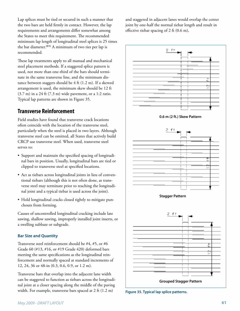
May 2009 - DRAFT LAYOUT 61
Lap splices must be tied or secured in such a manner that the two bars are held firmly in contact. However, the lap requirements and arrangements differ somewhat among the States to meet this requirement. The recommended minimum lap length of longitudinal steel splices is 25 times the bar diameter.(85) A minimum of two ties per lap is recommended.
These lap treatments apply to all manual and mechanical steel placement methods. If a staggered splice pattern is used, not more than one-third of the bars should termi-nate in the same transverse line, and the minimum dis-tance between staggers should be 4 ft (1.2 m). If a skewed arrangement is used, the minimum skew should be 12 ft (3.7 m) in a 24 ft (7.3 m) wide pavement, or a 1:2 ratio. Typical lap patterns are shown in Figure 35.
Transverse ReinforcementField studies have found that transverse crack locations often coincide with the location of the transverse steel, particularly when the steel is placed in two layers. Although transverse steel can be omitted, all States that actively build CRCP use transverse steel. When used, transverse steel serves to:
Support and maintain the specified spacing of longitudi-•nal bars in position. Usually, longitudinal bars are tied or clipped to transverse steel at specified locations.
Act as tiebars across longitudinal joints in lieu of conven-•tional tiebars (although this is not often done, as trans-verse steel may terminate prior to reaching the longitudi-nal joint and a typical tiebar is used across the joint).
Hold longitudinal cracks closed tightly to mitigate pun-•chouts from forming.
Causes of uncontrolled longitudinal cracking include late sawing, shallow sawing, improperly installed joint inserts, or a swelling subbase or subgrade.
Bar Size and Quantity
Transverse steel reinforcement should be #4, #5, or #6 Grade 60 (#13, #16, or #19 Grade 420) deformed bars meeting the same specifications as the longitudinal rein-forcement and normally spaced at standard increments of 12, 24, 36 or 48-in (0.3, 0.6, 0.9, or 1.2 m).
Transverse bars that overlap into the adjacent lane width can be staggered to function as tiebars across the longitudi-nal joint at a closer spacing along the middle of the paving width. For example, transverse bars spaced at 2 ft (1.2 m)
and staggered in adjacent lanes would overlap the center joint by one-half the normal tiebar length and result in effective tiebar spacing of 2 ft (0.6 m),
Figure 35. Typical lap splice patterns.
0.6 m (2 ft.) Skew Pattern
Stagger Pattern
Grouped Stagger Pattern

Continuousely Reinforced Concrete Pavement Design and Construction Guidelines62
Transverse ReinforcementField studies have found that transverse crack locations often coincide with the location of the transverse steel, particularly when the steel is placed in two layers. Although transverse steel can be omitted, all States that actively build CRCP use transverse steel. When used, transverse steel serves to:
Support and maintain the specified spacing of longitudi-•nal bars in position. Usually, longitudinal bars are tied or clipped to transverse steel at specified locations.
Act as tiebars across longitudinal joints in lieu of conven-•tional tiebars (although this is not often done, as trans-verse steel may terminate prior to reaching the longitudi-nal joint and a typical tiebar is used across the joint).
Hold longitudinal cracks closed tightly to mitigate pun-•chouts from forming.
Causes of uncontrolled longitudinal cracking include late sawing, shallow sawing, improperly installed joint inserts, or a swelling subbase or subgrade.
Bar Size and QuantityTransverse steel reinforcement should be #4, #5, or #6 Grade 60 (#13, #16, or #19 Grade 420) deformed bars meeting the same specifications as the longitudinal rein-forcement and normally spaced at standard increments of 12, 24, 36 or 48-in (0.3, 0.6, 0.9, or 1.2 m).
Transverse bars that overlap into the adjacent lane width can be staggered to function as tiebars across the longitudi-nal joint at a closer spacing along the middle of the paving width. For example, transverse bars spaced at 2 ft (1.2 m) and staggered in adjacent lanes would overlap the center joint by one-half the normal tiebar length and result in effective tiebar spacing of 2 ft (0.6 m),
TiebarsBoth traditional (Figure 36 and Figure 37) and multiple-piece (Figure 38) tiebars can be used at longitudinal joints to tie adjacent lane slabs together or to tie concrete shoul-ders to the mainline slab similar to jointed concrete pave-ments. As mentioned before, transverse reinforcement may be used in lieu of conventional tiebars. Tiebars are usually placed at mid-depth of the CRCP slab, but must be low enough to avoid damage if longitudinal joints are formed by sawing.
Figure 36. Longitudinal sawed joint with tiebars.
Figure 37. Longitudinal construction joint with tiebars.
Figure 38. Multiple-piece threaded tiebars.

May 2009 - DRAFT LAYOUT 63
If slipform pavers are used, multiple-piece tiebars, bent tiebars, or mechanically inserted tiebars are inserted into the concrete while still within the confines of the slipform paver. Bent tiebars are not recommended due to joint sepa-ration failures caused either by the weakened steel or failure to bend the tiebar straight before paving adjacent lanes. Mechanical tiebar inserters work well when located in the zone of vibration and should be allowed as long as the edge does not slump.
If fixed-form pavers are used, multiple-piece tiebars (or bent tiebars) are often attached to side forms.(86) Another option is to drill and epoxy tiebars in place. Tiebars should be tested to ensure they develop a pullout resistance equal to a minimum of three-fourths of the yield strength of the steel after 7 days, as determined by ASTM E 488, Standard Test Methods for Strength of Anchors in Concrete and Masonry.
Where tiebars are to be bent and later straightened, reinforc-ing bars of ASTM designation A 615 Grade 40 (Grade 300) should be used to prevent fatigue cracking in the bars. This requires the spacing to be somewhat less than that for Grade 60 (Grade 420) bars used as transverse reinforcement.
Good practice is to place tiebars approximately parallel to the grade, perpendicular to the longitudinal joint, and at the specified spacing. For example, a common arrangement of tiebars consists of 30 in (760 mm) long #4 or #5, Grade 40 (#13 or #16, Grade 300) deformed steel bars, if bend-ing is allowed, or Grade 60 (Grade 420) when no bending is allowed, spaced at 30 in (760 mm) center-to-center, and placed with half of the length on each side of the joint.
Tiebars should be placed at the design position within a tol-erance of ± 1.0 in (25 mm) vertically (or within the center 2/3 of the slab but lower than the joint saw cut) and ± 2.0 in (50 mm) horizontally.
Where corrosion is a concern, consideration should be given to the use of corrosion resistant steel or by coating the steel with a protective layer that extends at least 6 in (150 mm) beyond each side of the joint (see Figure 40).
Placing ReinforcementProper placement of reinforcing steel is an extremely critical aspect of CRCP construction. Detailed schematics should be provided by the contractor, approved by the engineer, and inspected in the field prior to paving to assure compli-ance with project standards and specifications. Longitudinal alignment and depth of the steel relative to the slab surface have a significant effect on CRCP performance.
Figure 39. Mechanical tiebar inserter. (Photo courtesy of HDR)
Figure 40. Protective coating on tiebar midsections.
Reinforcing steel may be placed manually on chairs or a transverse bar assembly, or mechanically using a tube feeder. The manual method, illustrated in Figure 41, offers the advantage of allowing easy inspection for the location of bars, laps, and splices, whereas the tube-feeding method can expedite the longitudinal reinforcement placing process.

Continuousely Reinforced Concrete Pavement Design and Construction Guidelines64
Field studies have shown no significant difference in the per-formance of CRCP with steel placed on chairs and CRCP with steel placed using tube feeders as long as both are done properly.(73) However, chairs are used far more frequently than tubes because of the demonstrated benefits of using transverse steel, and due to the perception that they are more likely to result in accurate placement of the steel.
Regardless, some quality assurance measures are needed to assure the steel has not shifted during the construction pro-cess. Some states are experimenting with the use of magne-tometers and ground penetrating radar for this purpose.
Manual Steel Placement (Chairs or Transverse Bar Assembly)In this method, reinforcing bars are attached to support assemblies prior to construction. These can consist of a variety of chair and support combinations, often tied to the transverse bars in some fashion. The supports must be sturdy enough to hold the bars within tolerances dur-ing placing and consolidating the concrete. For example, a recent project experienced problems when the plastic chairs proved to have inadequate stability and required strength-ening and additional ties at steel intersections. In addition,
Figure 41. Paver with steel on chairs.
Figure 42. Worker walking on reinforcing steel in Virginia.
supports should have a base configuration that provides adequate support for the weight of the steel and concrete as well as workers walking on the steel (see Figure 42) without collapsing, sinking into the base, or impeding the flow of concrete during placement and consolidation.

May 2009 - DRAFT LAYOUT 65
Using pins to anchor the reinforcing steel mat to prevent movement during paving is an item of contention. While some believe pinning the mat may cause horizontal crack-ing and/or a weakened bond between the concrete and steel, others believe the procedure is acceptable.
The arrangement and spacing of the steel supports should be such that the reinforcing bars are supported uniformly and in the specified position and do not move when concrete is placed. Bars should not permanently deflect or be displaced. Spacing of the supports is a function of the size and spacing of the reinforcing steel, the support provided by the pave-ment base layer, and the design of the chairs. As a general guideline, the spacing should not exceed 3 ft (0.9 m) trans-versely or 4 ft (1.2 m) longitudinally.
Usually, transverse bars are first placed on the individual chairs, or else a prefabricated transverse bar assembly is used. The longitudinal bars are then arranged in position (stag-gered for lapping, as discussed in Section 7.2.3). Next, the longitudinal bars are tied and secured to the transverse bars to maintain specified tolerances. Experience indicates that tying or clipping the longitudinal bars to the transverse bars at 4 to 6 ft (1.2 to 1.8 m) intervals along the longitudinal bars produces satisfactory results. States that are experi-enced with CRCP do not allow welding of longitudinal and transverse bars. Examples of steel placed on different types of supports are shown in Figure 43 and Figure 44.
Mechanical Steel Placement (Tube-feeding)When tube feeding steel, the longitudinal bars are distrib-uted on the base, approximately spaced, lapped, and tied manually. During placement, the longitudinal bars are raised up on rollers and threaded through bell-ended tubes within the concrete spreader where they are held at the specified vertical and horizontal positions as the concrete is placed between the tubes. Figure 45 shows a tube-feeding operation.
The tubes should be arranged and spaced to place the steel bars at the required depth and spacing. The location and depth of the steel should be verified on a routine basis. Dis-placement of steel may occur during the placement of the concrete due to internal vibration within the slipform paver. This method may cause bars to be displaced in a sinusoidal fashion, resulting in both high and low deviations relative to the slab surface. The vibration may also affect longitudinal alignment.
Checks of bar depth and alignment should therefore be made on a continuous basis by means of probing. Extra
Figure 43. Example of steel placed on chairs in Texas.
Figure 44. Example with two layers of steel placed on chairs.
Figure 45. Mechanical steel placement using tubes.

Continuousely Reinforced Concrete Pavement Design and Construction Guidelines66
tying is also needed to prevent bars from slipping. The bars and pavement should be marked to monitor any slipping as the feeder moves. The primary advantage of a physical measurement immediately behind the slipform paver is that process corrections can be made.
When using this method, a bar installer that is pulled by the spreader places the transverse bars at the specified spacing on the placed concrete. A saw-toothed rotary wheel then depresses the steel into the concrete at the specified location. Tiebars at the longitudinal joint are often inserted by either a wheel or hydraulically. Hydraulic insertion is favored since it does not drag, as a wheel does, and the finished slab sur-face is easier to close up which minimizes additional finish work.
Few, if any, contractors use the tube feeding method for steel placement. A number of problems have been reported with tube feeding, primarily related to ensuring the steel is at the proper depth in the pavement. Steel too high in the pavement has resulted in corrosion of the reinforcement and spalling of surrounding concrete, and even exposed steel in some instances. Steel too low in the pavement can result in undesirably wide crack widths. While tube feeding does eliminate the labor required for placing the steel on chairs, and permits access to the base in front of the paving opera-tion (although not for concrete placement), the potential problems associated with this technique may far outweigh the benefits.
InspectionSteel reinforcement should be properly inspected to ensure that spacing, splice lengths, and patterns are consistent with design requirements.(98) At a minimum, the follow-ing checks should be performed and documented prior to concrete placement:
Ensure all longitudinal lap and ties of all splices to assure •that the minimum lap of the reinforcing steel is main-tained (see Figure 46).
While it is important to check the distance between longi-•tudinal reinforcement bars (see Figure 47), it is even more important to ensure the correct number of bars is in place.
Periodically check that the reinforcing steel is placed •within the specified vertical tolerance. When chairs or transverse bar assemblies are used, this is accomplished prior to concrete placement by pulling a string line trans-versely across the roadway at the grade of the new pave-ment and measuring down to the reinforcing steel and
checking the steel for movement as the paver passes (see Figure 48).
Although the supports are designed to hold the steel at •the correct depth, the midpoint between the chairs should be checked for possible sags. When tube feeders are used, a probe, or ruler, is inserted to determine the depth to steel from the surface of the slab at several locations across the paving width.
Figure 46. Checking reinforcement lap.
Figure 47. Checking steel placement.
Figure 48. Checking for steel movement.

May 2009 - DRAFT LAYOUT 67
Ensure there are no broken steel chair welds or plastic •chair joints, bars are properly aligned, there are a sufficient number of wire ties on lap splices, and bars are lapped properly. Special precautions should be taken to prevent bar bending and displacement at construction joints.
Remove foreign materials prior to placing concrete.•
At a minimum, the following inspection techniques should be employed as the concrete is being placed:
Monitor the reinforcing steel at either the spreader or •paver to ensure that reinforcement is not displaced by the fresh concrete.
Regularly check the depth of the reinforcing steel behind •the paver, which can be accomplished when the concrete is plastic or hardened (see Figure 49).
The depth of reinforcing steel in plastic concrete may be ºdetermined as previously mentioned or by excavating to the steel and directly measuring the depth from the slab surface. Should the location not be correct, paving operations should stop until the problem is corrected. Generally, movement of reinforcement occurs more often with tube placement than when presetting steel on chairs.
Figure 49. Probing the fresh concrete to check the steel depth.
For hardened concrete, either a Ground Penetrating ºRadar (GPR) or magnetometer can be used to locate the position and depth of steel (after calibration with coring results). However, at this point, remedial mea-sures are limited, unlike a check during construction.
Troubleshooting and PrecautionsWhen placing CRCP on asphalt bases, both chairs and •transverse bar assemblies need base plates to prevent sink-ing into the base during warm weather.
Pinning the steel mat to the base should not be necessary •and may adversely affect long-term performance.
Longitudinal reinforcement should be spaced to avoid •longitudinal sawcut joints directly above a reinforcing bar.
Epoxy coated rebar should only be tied with coated tie •wires and any damage to the epoxy coating should be repaired according to the manufactures written instruc-tions before construction.
Mechanical insertion of tiebars should be allowed as long •as edge slumping is not a consistent problem.
Tack welding of reinforcing bars in the field should not be •allowed, as it can embrittle the steel.
Manholes and drop-inlets should be isolated from the •CRCP, and a reinforcing bar should be placed around the perimeter of the obstruction.
Any increase in pavement thickness should be accompa-•nied by an increase in reinforcement to maintain desired steel percentages.
CRCP should not be tied to noise walls, retaining walls, •or other structures without the pavement engineer’s approval. Typically, this is rarely if ever done on a given project.
Paving should not be allowed until reinforcement sche-•matics have been approved and reinforcement has passed field inspection.


CHAPTER 9
PAVING PRACTICES FOR CRCP

Continuousely Reinforced Concrete Pavement Design and Construction Guidelines70
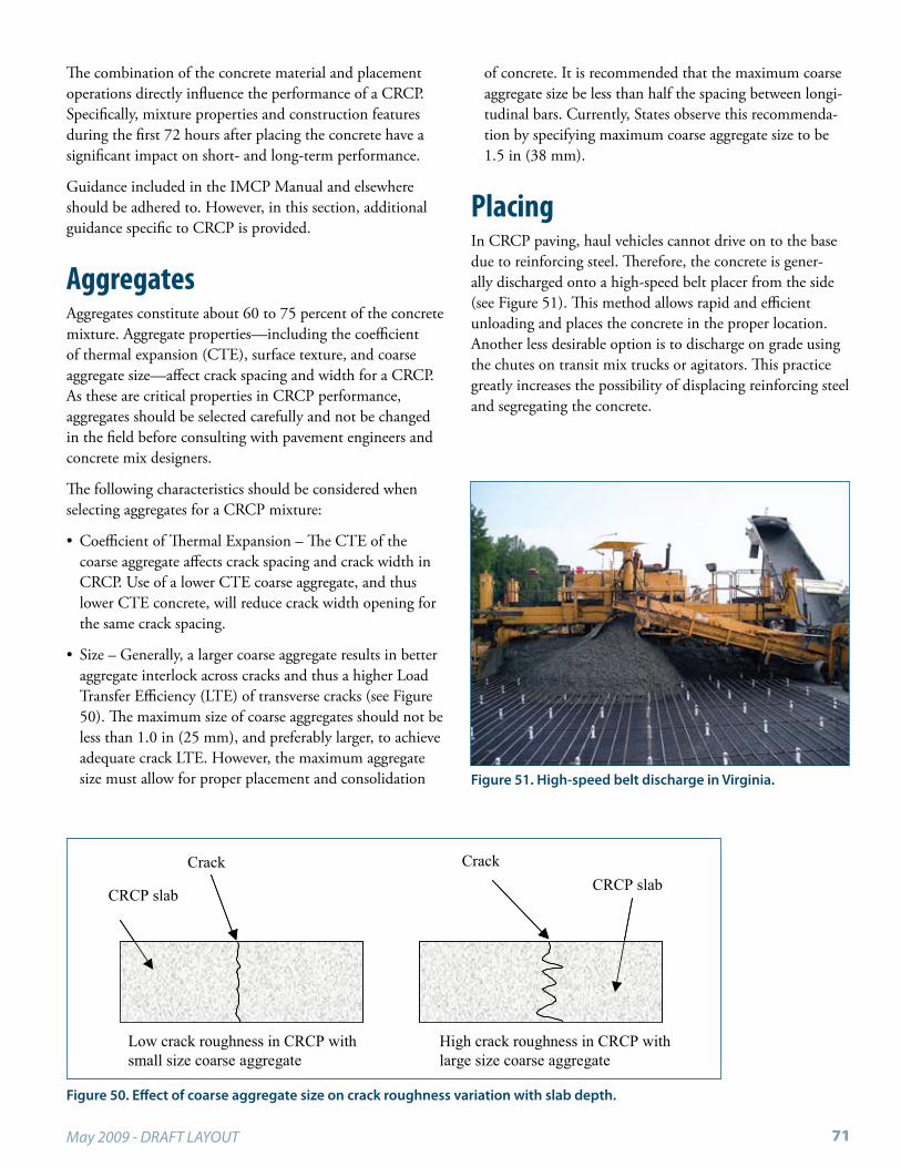
May 2009 - DRAFT LAYOUT 71
The combination of the concrete material and placement operations directly influence the performance of a CRCP. Specifically, mixture properties and construction features during the first 72 hours after placing the concrete have a significant impact on short- and long-term performance.
Guidance included in the IMCP Manual and elsewhere should be adhered to. However, in this section, additional guidance specific to CRCP is provided.
AggregatesAggregates constitute about 60 to 75 percent of the concrete mixture. Aggregate properties—including the coefficient of thermal expansion (CTE), surface texture, and coarse aggregate size—affect crack spacing and width for a CRCP. As these are critical properties in CRCP performance, aggregates should be selected carefully and not be changed in the field before consulting with pavement engineers and concrete mix designers.
The following characteristics should be considered when selecting aggregates for a CRCP mixture:
Coefficient of Thermal Expansion – The CTE of the •coarse aggregate affects crack spacing and crack width in CRCP. Use of a lower CTE coarse aggregate, and thus lower CTE concrete, will reduce crack width opening for the same crack spacing.
Size – Generally, a larger coarse aggregate results in better •aggregate interlock across cracks and thus a higher Load Transfer Efficiency (LTE) of transverse cracks (see Figure 50). The maximum size of coarse aggregates should not be less than 1.0 in (25 mm), and preferably larger, to achieve adequate crack LTE. However, the maximum aggregate size must allow for proper placement and consolidation
Figure 50. Effect of coarse aggregate size on crack roughness variation with slab depth.
Low crack roughness in CRCP with small size coarse aggregate
High crack roughness in CRCP with large size coarse aggregate
CRCP slabCrack
CRCP slab
Crack
of concrete. It is recommended that the maximum coarse aggregate size be less than half the spacing between longi-tudinal bars. Currently, States observe this recommenda-tion by specifying maximum coarse aggregate size to be 1.5 in (38 mm).
PlacingIn CRCP paving, haul vehicles cannot drive on to the base due to reinforcing steel. Therefore, the concrete is gener-ally discharged onto a high-speed belt placer from the side (see Figure 51). This method allows rapid and efficient unloading and places the concrete in the proper location. Another less desirable option is to discharge on grade using the chutes on transit mix trucks or agitators. This practice greatly increases the possibility of displacing reinforcing steel and segregating the concrete.
Figure 51. High-speed belt discharge in Virginia.

Continuousely Reinforced Concrete Pavement Design and Construction Guidelines72
ConsolidationConcrete is consolidated to achieve required strength and durability, reduce entrapped air, and ensure bonding between the concrete and steel. Thus, adequate consolida-tion is a critical factor in achieving desirable long-term performance of CRCP. Like all concrete paving, concrete used in CRCP is consolidated using mechanical vibrators. Though rare, over-vibration can cause aggregate segregation, excessive bleeding, and reduction in entrained air. Further-more, vibrator trails indicate failing vibrator equipment.
Either over-vibration or under-vibration can reduce bond-ing strength between steel and concrete and thus result in poor CRCP performance. It should be noted that problems associated with under-vibration of concrete appear more frequently than those associated with over-vibration.
Vibrators must not come in contact with reinforcing steel bars for extended periods of time because this can cause weakened mortar to concentrate around the steel bars. Also, contact between vibrators and joint assemblies, base material, and side forms must also be avoided for the same reason. Extra care should be taken to attain sufficient con-solidation by manually vibrating at construction joints and leave outs.
JointsLongitudinal Control JointsLongitudinal control joints, otherwise known as contrac-tion, hinged or warping joints are necessary to relieve stresses caused by concrete shrinkage and temperature gradients and changes in monolithically placed slabs that are wider than 14 ft (4.3 m) to control longitudinal cracking (see Figure 36 for a typical photo). These joints are generally formed by sawing the hardened concrete, but early entry saws have proven to work as well.
The recommended sawing depth is one-third of the as-constructed slab thickness to ensure an adequate weakened plane. Longitudinal control joints must be spaced to avoid sawing directly over a longitudinal steel bar. Care must be taken to not cut the tiebars across control joints.(85) Saw cuts less than one-third the slab depth may not be adequate to form a crack at the planned location and can lead to random longitudinal cracking.
If random cracking should occur, the CRCP transverse rein-forcement will aid in holding the cracks together. In some
cases, cross-stitching can possibly be used to ensure that longitudinal cracks will remain tight. If any tiebars are dam-aged during saw cutting operations, cross-stitching should be done at those locations.(93)
Longitudinal Free JointsLongitudinal free joints are used to reduce the amount of steel needed in the transverse direction, to facilitate con-struction, and to isolate structural elements from the CRCP (see Figure 52). These joints are typically placed at the edge of median concrete traffic barriers, at the top of wingwalls, mechanically stabilized earth walls, or cast-in-place retaining walls to isolate the pavement movement from the move-ment of the structures. Since the amount of transverse steel needed is based on subgrade drag theory, a longitudinal free joint at the centerline of the pavement may reduce the amount of transverse steel needed by one-half. Longitudinal free joints should only be placed where load transfer and joint movement in the horizontal or vertical directions is not a critical consideration.
Transverse Construction JointsTransverse construction joints are installed at the end of each day’s paving operation or other placement interrup-tions (whenever the placing of concrete is suspended for more than 30 minutes). In early CRCP construction, these joints often failed. However, proper design and construction proved these non-working transverse joints could perform as well as random transverse cracks.
Transverse construction joints are formed by means of a suitable split header board conforming to the cross section of the pavement. The header board should be secured verti-cally in place perpendicular to the surface of the pavement. Longitudinal reinforcing bars should extend through the split in the header board and be supported beyond the joint by chairs. On the leave side of the header, reinforcing steel should be covered with plates of wood so as to allow easy
Figure 52. Longitudinal free joint.

May 2009 - DRAFT LAYOUT 73
removal of the concrete that is carried over the header (see Figure 54). Before resuming paving, the header board is removed. Figure 53 and Figure 54 show paving operations beginning and ending at transverse construction joints.
Transverse construction joints are typically smooth faced butt joints that do not benefit from aggregate interlock. These joints should not be edged or sealed. An important
factor in good CRCP performance is continuity of load transfer; thus, special reinforcing bar arrangements are needed to replace load transfer capacity lost because of the smooth joint face and to handle early stress concentrations. Several States require adding 72 in (1.8 m) long tiebars at the construction joints, placed adjacent to every other lon-gitudinal bar. These additional bars typically have the same diameters, grade, and depth of the regular longitudinal steel bars. This additional reinforcement prevents movement and reduces the possibility of cracks developing in the adjacent slabs.
Pavement areas adjacent to both sides of the joint should receive additional consolidation from hand vibrators inserted into the concrete along the entire length of the joint. These areas should extend at least 10 ft (3 m) from the joint. Ensure vibrators do not excessively contact steel, forms, or base.
A recent report by the Texas Transportation Institute provides additional details for CRCP transitions, including details for transverse construction joints.(123)Figure 53. Transverse (start) construction joint.
Figure 54. Transverse construction joint (header).

Continuousely Reinforced Concrete Pavement Design and Construction Guidelines74
BlockoutsBlockouts are needed to allow for obstructions in the CRCP, such as drop-inlets, manholes, and foundations for luminar-ies. These types of obstructions in CRCP should be avoided if possible or otherwise limited to outer edges of shoulders. Typically, the perimeter of the blockout is an isolation joint where the width of the joint is 1.5 in (40 mm). Whereas an isolation joint in normally constructed with preformed fiberboard material, the blockout joint should instead use a compressible material that does not absorb water. In addi-tion, approximately 3 in (75 mm) outside the perimeter of the blockout should be two concentric reinforcing bars of the same size and grade as the longitudinal reinforcing steel in the CRCP. A schematic detail is shown in Figure 55.
Construction Techniques for Controlling Crack SpacingField studies in Texas and elsewhere have investigated the control of crack spacing by inducers at prearranged loca-tions.(70) The Texas study was conducted on CRCP that was constructed in hot weather (90 to 100°F or 32 to 38°C).
Crack induction was achieved by the use of two differ-ent methods: sawcutting a shallow notch in the pavement surface and metallic crack inducers. Early-age sawcutting techniques (consisting of a portable, light saw) were used for surface notching. Notches were made roughly 4 hours after concrete placement and resulted in cracks that initiated at the surface. Metallic crack inducers were placed in both single and stacked layer configurations and were anchored
Figure 55. CRCP Blockout Schematic.
to the double layer of longitudinal reinforcement to provide support against the flow of fresh concrete during paving operations. Crack inducers initiate cracks at the interior of the pavement thickness.
Based on the limited data from these research studies, it appears that surface crack initiation (using the early-age notching technique) is more effective than interior crack initiation (using inducers) in controlling the crack pat-tern. New studies also show that plastic tape inserts can be effective in initiating transverse cracks. However, more work needs to be done to prove the viability of this technique.
Fast-Track PavingFast Track paving is a process of using proven techniques for concrete paving that will allow the pavement to be open to traffic at an earlier that normal age, generally in less than 12 hours. The necessary early strengths are normally achieved with an optimized mixture and thermal insulation.
The following special considerations need to be accommo-dated when fast tracking CRCP construction:
Steel Stresses – High early strength gains and the pos-•sibility of increased shrinkage in the concrete need to be evaluated to ensure that excessive steel stresses do not develop.
Steel Corrosion – Corrosive accelerators like CaCl should •never be used to achieve high early strength because they may result in corrosion and structural failure. Finer cements are often used but cause decreased workability

May 2009 - DRAFT LAYOUT 75
that requires additional water or a water reducing admix-ture. By adding more water, permeability will increase creating a greater risk for corrosion. Permeability is also increased by plastic shrinkage cracks that may result from heat caused by faster hydrating cements.
Temperature Control – Software like FHWA HIPERPAV •or CRSI PowerPave coupled with maturity sensors, should be used to ensure temperature controls are adequate to achieve the desired strength within the desired time con-straints and that the removal of the thermal blankets do not cause thermal shock.
Environmental Influences during ConstructionClimatic conditions such as ambient temperature, rela-tive humidity, and wind speed during construction affect both crack formation and pattern in CRCP through a built-in thermal gradient and set temperature. Shrinkage and contraction stresses, which are the result of restrained movement caused by temperature and moisture changes and slab friction with base layers, cause cracks to develop at early ages. These cracks are likely to occur at an early age if the temperature rise of the concrete is not held to a minimum and the heat is not allowed to dissipate at a reasonable rate, or if the concrete subjected to a severe temperature gradient.
Hot Weather Conditions Hot weather concreting is that when temperatures are above 90°F or 32°C. Particular concern exists when these condi-tions are accompanied by higher wind speeds and low rela-tive humidity. Concrete temperatures will generally be high as a result, and there is therefore an increased loss of water due to evaporation and an increased potential for early-age cracking. Early-age cracking due to hot weather tends to be wider than cracks that develop at later ages and can thus be more damaging to CRCP performance. In addition, rapid initial or false set may reduce the effectiveness of vibration in consolidating concrete around steel reinforcing bars.
Concrete Placement Time and SeasonEarly-age crack formation is related to both season and time of the day at which the concrete is placed. Recent CRCP studies in Texas indicate that concrete placed in warmer temperature experience more cracking over time and poorer
crack pattern than concrete placed in cooler temperature. Also, concrete placed during daytime experienced crack formation much more quickly than concrete placed at night.(71) The FHWA HIPERPAV software can be used to identify the optimum time of day for paving to fit the cur-rent and forecasted environmental conditions to improve the performance of a CRCP. While night paving may not be desirable in urban areas (e.g., due to construction noise) the demonstrated improved performance and reduced conges-tion may help to justify paving at night.
Generally, CRCP placed in cool weather conditions per-forms better (longer crack spacing and smaller crack width) than CRCP placed in hot weather conditions. However, adverse weather conditions must be considered under these circumstances as well. Guidance provided in the IMCP Manual and elsewhere should be sought.
Using FHWA HIPERPAV and CRSI PowerPaveBoth FHWA HIPERPAV and CRSI PowerPave are soft-ware analysis tools that predict the early-age performance of CRCP. These analyses are based on support layer restraint, concrete materials and quantities, environmental conditions (both existing and predicted), and construction methods. These tools can be used for the following:
Determining optimum paving times.•
Evaluating mixture changes that could be used to either •reduce or increase the heat of hydration.
Optimizing mixture designs as they interact with expected •paving conditions.
Determining the window for sawing operations of the •longitudinal joints.
Determining when and what additional curing may be •needed.
Estimating opening times for traffic. Recent advance-•ments in concrete maturity and on site weather moni-toring now allow this to be done in real time (FHWA SmartCure).
Reducing the risk of thermal shock cracking.•
Determining when it is safe to stop or start paving due to •adverse weather.(115)


CHAPTER 10
TERMINAL OR TRANSITION TREATMENTS


May 2009 - DRAFT LAYOUT 79
The free end of a CRCP can be expected to move up to 2 in (50 mm) longitudinally due to environmental changes in temperature and moisture depending on the frictional resis-tance or the viscoelastic properties of the underlying layer. To mitigate this, terminal (or transition) joints are placed where a CRCP abuts a structure or another pavement type. These joints facilitate the movement of the CRCP without damaging the adjacent structures.
An ideal terminal joint system would be one that fully allows or constrains the expected movement of CRCP while fulfilling the requirements of maintaining a smooth riding surface, preventing intrusion of water into the base, and providing necessary load transfer across the joint.(89,94) There are three commonly used CRCP terminal/transi-tion joints, and a fourth type has been used in Texas and Australia:
1. Expansion joints,
2. Wide flange beam joints,
3. Anchor Lugs, and
4. Seamless pavement transition at bridges.
Use of these transitions varies depending on the supporting layers, importance, and location of controlling the move-ment of CRCP.
Expansion JointsWhen transitioning to a bridge, as illustrated in Figure 56, there are two key lessons that have been learned to help prevent the proverbial “bump at the bridge”. First is to
continue the CRCP base layers under the bridge approach slab to the bridge cap. Terminating the CRCP surface and base layers at one point has been shown to be problematic. The second lesson is that if there are fat clays in the sub-grade where an embankment for an overpass will be placed, then the clays should undergo a geotechnical evaluation to determine anticipated movements and treated accordingly. Pavement smoothness and structure can be significantly affected by as little as 1 in (25 mm) of differential settlement in 30 ft (10 m).
Expansion joint systems are designed to accommodate expected CRCP end movements and are the least expensive to construct of the various terminal joint systems. Mainte-nance may be required to clean out the joint and replace the seal, but construction is relatively simple, inexpensive, and quick.
Performance of expansion joints is significantly improved by incorporating a sleeper slab and extending base layers under the sleeper slab. Experience has shown that sleeper slabs have a tendency to tilt when base layer(s) do not extend under the sleeper slab. Multiple expansion joints may be needed, as shown in Figure 56, when it is critical for the abutting pavement not to move (e.g., in a jointed pavement toll section). Note that base layers were carried under both sleeper slabs.
Figure 57 and Figure 58 show two types of typical expan-sion joint systems at a CRCP transition to a HMA pave-ment. Note that transition in the base layers is provided away form the transition in the surface layers.
Figure 56. Expansion Joint, CRCP to JCP or a bridge.
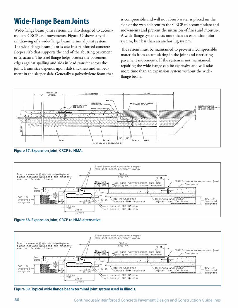
Continuousely Reinforced Concrete Pavement Design and Construction Guidelines80
Wide-Flange Beam JointsWide-flange beam joint systems are also designed to accom-modate CRCP end movements. Figure 59 shows a typi-cal drawing of a wide-flange beam terminal joint system. The wide-flange beam joint is cast in a reinforced concrete sleeper slab that supports the end of the abutting pavement or structure. The steel flange helps protect the pavement edges against spalling and aids in load transfer across the joint. Beam size depends upon slab thickness and embed-ment in the sleeper slab. Generally a polyethylene foam that
Figure 57. Expansion joint, CRCP to HMA.
Figure 58. Expansion joint, CRCP to HMA alternative.
is compressible and will not absorb water is placed on the side of the web adjacent to the CRCP to accommodate end movements and prevent the intrusion of fines and moisture. A wide-flange system costs more than an expansion joint system, but less than an anchor lug system.
The system must be maintained to prevent incompressible materials from accumulating in the joint and restricting pavement movements. If the system is not maintained, repairing the wide-flange can be expensive and will take more time than an expansion system without the wide-flange beam.
Figure 59. Typical wide flange beam terminal joint system used in Illinois.

May 2009 - DRAFT LAYOUT 81
In corrosive environments (e.g., where chloride deicing agents are applied), the beam must be protected against cor-rosion. Careful workmanship is critical to the performance of wide-flange terminal joint systems. The following guide-lines are particularly important for installing these systems:
The subgrade in the joint area should be compacted •thoroughly, similar to the rest of the CRCP project before excavating for the sleeper slab.
The sleeper slab must be cast with the wide flange beam •in place and should be allowed to gain sufficient strength before the pavement is placed.
The base/subbase quality in the joint area should be simi-•lar to the rest of the project; including the support under the sleeper slab. If the subgrade is considered a quality material this may not be necessary.
The steel beam should match the cross slope and road •profile of the pavement.
Anchor LugsAnchor lug terminal treatments generally consist of heav-ily reinforced, rectangular, transverse, concrete lugs placed in the subgrade to a depth below frost penetration prior to the placement of the pavement. This system is by far the most expensive to construct and repair. Anchor lug systems are installed at the end of CRCP sections to restrain most of the terminal movement by transferring movement forces into the soil mass through passive and shear resistance of the soil. Since this system relies on passive resistance of the soil, it may not be effective where cohesionless soils are encountered.
It is important that reinforcing steel in these systems be adequate to prevent shear failure and the system be designed to resist rotation. Field studies indicate that “lug rotation” roughness has occurred in designs that include four lugs at 40 ft (12 m) spacing, but no significant rotation is known to have occurred in designs that have three lugs spaced at 20 ft (6 m). Lugs are typically 4 ft (1.2 m) deep and 2 ft (0.6 m) wide. Figure 60 shows a typical drawing of an anchor lug terminal joint system. The following guidelines are particu-larly important for installing these systems:
Figure 60. Typical anchor lug terminal joint system.(85)

Continuousely Reinforced Concrete Pavement Design and Construction Guidelines82
The subgrade in the joint area should be compacted •thoroughly, similar to the rest of the CRCP project before excavating for the lugs. It is desirable to continue base/subbase placement through the lug-anchor area and to excavate through the base/subbase to form lug trenches.
Lugs should be cast directly into trenches in the embank-•ment without forms to achieve maximum resistance. However, concrete must not be contaminated by earth falling from trench sidewalls.
Reinforcing bars must be held securely in place during •concrete placement.
Concrete must be consolidated effectively throughout the •lug area.
Figure 61. Seamless pavement transition for bridges.
Seamless TransitionsThe seamless CRCP-to-structure transition is an enhance-ment that eliminates the need for transverse joints by connecting CRCP longitudinal steel directly into bridge deck reinforcement. This creates continuous reinforcement through the CRCP, the transition zone between the CRCP and bridge deck, and through the bridge deck itself.
The concept is similar to the process being used to reduce the number of joints in bridge decks through the use of link slabs at internal piers and has the following advantages: reduced maintenance, improved smoothness, simplified construction and cost savings (see Figure 61).(121) Although only used on a limited basis thus far in Australia, Europe, and Texas it has the potential to greatly improve the effi-ciency CRCP construction and performance of CRCP at bridge transitions.

CHAPTER 11
CONSTRUCTING CROSSOVERS


May 2009 - DRAFT LAYOUT 85
CRCP design procedures and specifications are developed around the concept of continuity in load transfer and ther-mal stress resistance in a monolithic pavement slab. Thus, temporary gaps in CRCP should be avoided as much as possible. Giving proper consideration to the paving schedule can minimize the necessity for these gaps. However, tem-porary gaps are necessary in some paving situations, such as providing a haul road crossing or an intersection where cross traffic must continue to flow.
These gaps are referred to as leave-ins or leave-outs. If pav-ing in the gap area precedes mainline construction, the gap pavement is referred to as a leave-in; if it follows mainline construction, the gap is referred to as a leave-out.
Leave-InsIf the concrete is placed in the gap before paving the main-line, the crossover is referred to as leave-in. Leave-ins are preferred to leave-outs because movement of the hardened concrete of the short pavement section is not likely to have a damaging effect when abutting freshly placed concrete of the mainline section. Crack spacing in the leave-in may be greater than what develops in the mainline due to free movement of the ends. However, additional cracks will develop over time after it is connected to the mainline pavement.
Normal lap staggering and construction joint procedures can be used in leave-ins. Extra care should be taken to pro-vide high quality concrete, effective consolidation, proper reinforcement placement, and a smooth surface. If the leave-in is in the form of an intersection, the two sides of the intersection can be constructed separately, or the entire intersection can be constructed at once.
Leave-OutsIf the concrete is placed in the gap after paving the main-line, the crossover is referred to as leave-out. A major con-cern with leave-outs is that the movement of the mainline hardened concrete can overstress the fresh concrete in the gap, causing cracking, crushing, and permanent loss of bond between concrete and steel in the leave-out area. Thus, this type of crossover should not be used unless it is the only
practical method of gap construction. In fact, some agencies do not permit the use of leave-outs.
In the event a leave-out does become necessary, the follow-ing precautions should be taken to reduce distress in the leave-out concrete:(85,89)
Leave-out should be at least 100 ft (30 m) in length.•
Leave-outs require 50 percent more longitudinal •deformed bars of the same nominal size as the regular reinforcement. The additional reinforcement should be spaced evenly between every other regular longitudinal reinforcing bar and should be bonded at least 3 ft (1 m) into the pavement ends adjacent to the leave-outs. All regular longitudinal reinforcement should extend into the leave-out a minimum of 8 ft (2.5 m). Required splices should be made the same as those in normal construction.
Leave-outs should be paved during stable weather con-•ditions when the daily temperature range is small. This condition is likely to exist when the sky is cloudy and the humidity is high.
If it becomes necessary to pave a leave-out in hot weather, •the temperature of the concrete in the free ends should be stabilized by placing an adequate layer of insulating material on the surface of the pavement to minimize movement. Curing compound should be applied to new concrete in a timely manner. Insulation material should remain on adjacent pavement until the design modulus of rupture of the leave-out concrete is attained.
Because of the shortness of the steel spacing, extreme care •should be exercised in placing and consolidating concrete to prevent honeycombing or voids under reinforcement.
Place terminal treatments at each end of the leave-out.•
Temporary CrossoversThis type of crossover is sometimes needed to accommodate truck movement across the grade after reinforcing steel is in place. These crossovers can be installed by placing wooden mats over the steel after temporary removal of bar supports. The wooden mats can be designed so that cleats underneath are spaced to fit between longitudinal and transverse rein-forcing members


CHAPTER 12
CONSTRUCTING SHOULDERS AND RAMPS


May 2009 - DRAFT LAYOUT 89
Concrete and asphalt shoulders, auxiliary lanes, and ramps can be constructed in conjunction with a mainline CRCP. The design and construction of these components will affect the cost of CRCP construction, maintenance requirements and can significantly impact long-term performance of the mainline CRCP.
Shoulders and Auxiliary LanesTypical shoulder designs for CRCP traffic lanes include:
Jointed plain concrete pavement placed after the mainline •traffic lanes without dowels (when not expected to carry traffic). Tiebars are used to provide load transfer.
HMA placed adjacent to an extended outside lane of the •mainline CRCP slab. The mainline slab should extend at least 2 ft (0.6 m) into the shoulder area to provide an interior loading condition for traveled lanes.
CRC with the same cross-section as main lanes. Often •times a State will widen the shoulder so that it may serve as a traffic lane when needed.
Key features to consider in the design and construction of shoulders and auxiliary lanes include the following:
Amount of load transfer provided by the shoulder (or aux-•iliary lane) through the design life of the pavement.
Ability to prevent the intrusion of moisture to susceptible •layers under the loaded area of the pavement.
Maintenance requirements.•
Ability to use shoulder for regular traffic (emergencies, •increased capacity, and/or parking).
Concrete ShouldersConcrete shoulders should be tied to the mainline by either extending the transverse steel from the mainline CRCP into the shoulder with a longitudinal contraction joint provided at the juncture of the traveled lane and the shoulder, or through a longitudinal construction joint with properly spaced, aligned, and sized tiebars. Tiebars are required between the mainline slab and concrete shoulder to provide designed load transfer and prevent water infiltration into the pavement and base structure.
Tiebar installation at the shoulder follows the same con-struction practice as provided in Section 7.4 at longitudinal mainline construction joints. Almost all states have aban-doned the use of Grade 40 (Grade 300) tiebars and the practice of bending the bars, due to joint separation issues.
Some agencies are now using a multi-piece threaded tiebar as was shown in Figure 38. One half of the bar is tied to the reinforcement in the CRCP traffic lane. After concrete is placed, the other half is threaded into this bar.
Keyed longitudinal joints are not recommended and should never be used for pavements less than 10 in (250 mm) thick. If used for pavements 10 in (250 mm) or greater in thickness, keyways should be placed at mid-slab depth to ensure maximum strength. Proper concrete consolida-tion, both above and below the keyway, is essential and the joint must be tied with reinforcing steel as previously recommended.
Where plain jointed concrete shoulders are used adjacent to CRCP, the tied concrete shoulder should be sawed trans-verse to the direction of traffic to a depth of one-third the pavement thickness at no more than 15 ft (5 m) intervals. If the shoulder will be used for mainline traffic, or substantial parked truck traffic, consideration should be given to use of dowels at these joints to prevent faulting and provide additional load transfer. Plain jointed concrete shoulders should not be constructed integrally with or before the mainline CRCP, as the transverse saw cuts in the integrally constructed shoulders would propagate as cracks across the mainline CRCP.
Corrugations that are impressed in plastic concrete have proven to be an effective contrast between shoulder and mainline pavements alerting drivers they are moving onto the shoulder. The width and depth of the corrugations are dependent on roadway average speed. In a 50 to 70 mph (80 to 110 kph) range, a width of 4 to 6 ft (1 to 2 m), and a spacing of 60 to 100 ft (18 to 30 m) are appropriate.(89) Care should be taken to make certain that the impressed corrugations meet the plan details throughout the harden-ing process and that the concrete is not weakened by late disturbance.(89)
Asphalt ShouldersThe FHWA Technical Advisory T5040.29 recommends that shoulders be constructed of the same materials as the mainline pavement to facilitate construction, improve per-formance, and reduce maintenance costs.(96) The Advisory explains that tied concrete shoulders in lieu of flexible shoul-ders will minimize problems associated with infiltration of surface water into foundation through lane-shoulder longi-tudinal joints. However, if HMA shoulders are selected, the following guidelines should be considered:
Include anti-stripping agents in the HMA mixture used •on the shoulder.

Continuousely Reinforced Concrete Pavement Design and Construction Guidelines90
Include proper subdrainage such as edge drains beneath •the lane/shoulder joints, or daylighted treated permeable bases, so as to drain water infiltrating the lane-shoulder joint and to keep the entire base structure free of mois-ture. Sub-drainage is discussed in Section 6.2 of this guide.
Ensure that the HMA is compacted to adequate density, •particularly at lane-shoulder interface.
Widened LaneThe use of full-width CRC paved shoulders is desirable for many reasons. However, the additional cost of this design may not be warranted on all projects. Some agencies build widened outside lanes instead of using full-width paved shoulders. A monolithic widening of at least 1 ft (0.3 m) outside of regular painted edge strips is commonly used. Widened lanes are only effective when travel lanes are striped at 1 ft (0.3 m) to help guide vehicles within the traffic lane and not on the widened area. Widened lanes reduce the number of edge loadings; thereby reducing development of edge punchouts. Placement of rumble strips on the shoulder portion of a widened lane should also be considered.
Concrete RampsConcrete ramps adjacent to mainline CRCP can be con-structed as CRCP or jointed concrete pavement. Longitu-dinal joints between the ramp and mainline CRCP should be designed and tied as the lane-lane or lane-shoulder tied longitudinal joints that are discussed in Section 8.4 of this Guide.
When the ramp is constructed as CRCP or as a jointed con-crete pavement with a joint spacing of 15 ft (5 m) or less; tiebars can be placed uniformly at the same spacing used in the adjacent longitudinal joint. If the ramp is constructed as a jointed concrete pavement with a joint spacing greater than 15 ft (5 m), only the middle third of each slab between joints should be tied because excessive stresses in the CRCP can result from large thermal movements of the tied ramp near transverse joints.(89)
Take extra care in the ramp concrete consolidation (espe-cially around construction joints) and finishing to achieve concrete uniformity and satisfactory ride quality.
CRCP ramps will require terminal treatments at their point of transition to the adjoining roadway.

CHAPTER 13
CRCP OVERLAY CONSTRUCTION


May 2009 - DRAFT LAYOUT 93
CRCP has been effective as an overlay for deteriorated com-posite, rigid, and flexible pavements. CRCP overlays have also been effective over pavements in good condition for the purpose of adding capacity or structure when traffic loads are heavier than expected. Only in cases where separation layers or overlay thicknesses were inadequate (e.g., less than 7 in (178 mm)) did CRCP overlays not perform well.
CRCP overlays are similar to new CRCP in terms of mechanical behavior and primary distress (e.g., wide cracks and punchouts). Generally, all concrete and reinforcement
construction guidelines that have been discussed previously for new CRCP apply to CRCP overlays. CRCP overlays are designed and constructed as bonded or unbonded overlays depending on the existing pavement type and condition.
Additional guidance for CRCP Overlays can be found in the Guide to Concrete Overlays developed by the National Concrete Pavement Technology Center. An additional reference is the “Concrete Overlays for Pavement Rehabili-tation” guidance, published as ACI document 325.13R-06.


CHAPTER 14
CONSTRUCTION INSPECTION


May 2009 - DRAFT LAYOUT 97
Quality construction is a key factor in the long-term exceptional performance of CRCP and does not happen by chance.
In addition to guidance found in the Materials and Con-struction Optimization (MCO) Guidelines and elsewhere, the following items should be checked on CRCP projects:
Crack widths that exceed the design criteria, which would •be in the range of greater than 0.02 in (0.5 mm) and punchouts caused by:
Insufficient steel lap length, º
Steel placed too low in the slab, º
Less-than-design slab thickness, º
More-than-design slab thickness, resulting in a reduced ºsteel percentage,
Poor bonding of the steel to the concrete caused by: º
Insufficient consolidation of the concrete, -
Sudden temperature drops greater than 20°F (10°C) -during construction, and/or
Steel heavily rusted, soiled, or coated with curing -compounds, grease, or oils without adequate cleaning.
Surface delaminations caused by steel too high in the slab, •large temperature swings, or inadequate vibration.
Punchouts in CRCP overlays due to a lack of repairs to •serious underlying pavement deteriorations.
Construction related distress can be greatly minimized or even eliminated with proper attention to detail, care during construction, and sound quality control.. Several DOTs have constructed quality CRCP that have shown excel-lent performance. Examples of inspection tasks are listed in Table 6, which summarizes the items that need special attention during the construction of CRCP. The details of these items are discussed throughout this guide.
Table 6. Summary of Inspection Tasks.
Critical Inspection Item Importance Suggested Precautionary Measures
Subgrade
Uniformity of subgrade support
Minimize differential localized settlements along CRCP project over time.
Use heavy roller to proof roll length of pavement, •identify, and correct soft areas.Use DCP or GPR at regular intervals to identify location •of very soft soils.Measure the density and moisture content after •compaction of each layer.
Grading of subgrade Any abnormality in the subgrade will likely be reflected in the CRCP surface. Proper subgrade grading helps achieve proper thickness and smoothness in the base and surface of CRCP.
Check for stringline sag.•Check the beginning and ending of the stringlines.•Continually “eyeball” the stringline for straight grades •and smooth transitions.Continually check if the sensors are connected and •operating properly.
Base/Subbase(s)
Friction between CRCP slab and support
Affects crack spacing. Using a push-off test, verify that the as-constructed friction between CRCP and the support layer is consistent with as-designed friction (e.g., do not reduce this friction during construction unless it was explicitly designed).
Binder content in asphalt treated base
Asphalt base needs to provide adequate support over the entire design life and thus must avoid stripping. Critical to minimize development of punchouts and loss of smoothness.
Evaluate mixture as constructed, and conduct stripping tests to ensure adequate film thickness around the aggregates.

Continuousely Reinforced Concrete Pavement Design and Construction Guidelines98
Table 6. Summary of Inspection Tasks. (continued)
Critical Inspection Item Importance Suggested Precautionary Measures
Base/Subbase(s) (continued)
Stability and uniformity of unbound aggregate base
Unbound aggregate base needs to provide adequate support over the entire design life. Critical to minimize development of punchouts and loss of smoothness.
Measure gradation and density of base course and avoid segregation.
Cement treated base (CTB) or lean concrete base
Generally used over weak or variable subgrades to provide uniform support that is not subject to water damage support over the entire design life. Critical to minimize development of punchouts and loss of smoothness. Erosion related to strength of base.
In the field, use density as a check for moisture content •and strength. Use appearance to check for consistency. Initially and when density and visual check indicate the need take cores and check strengths (compression or indirect tensile).At the plant, regularly check compressive or indirect •tensile strength for consistency and compliance.Longitudinal joints should match those in the CRCP •slab.Pave during proper climatic conditions and use proper •curing process.
Concrete
Strength Affects crack spacing, crack width, punchouts of CRCP
Sample at site prior to or during placement of concrete and check t assure that unwanted water is not being added.
Deviation of as-constructed slab thickness from as-designed value
Affects crack spacing, crack width, punchouts of CRCP. Thicker as-built slab results in lower percentage of steel and thinner slab results in punchouts. Consistent thickness is important to achieving smooth surface.
Constantly monitor in plastic concrete using depth •checker.If necessary, verify with cores after hardening.•
Consolidation To provide sufficient bonding between steel and concrete and concrete durability that is necessary to protect the steel from corrosion.
Check the density of the concrete.•Check the frequency, amplitude, centrifugal force, and •radius of action of the mechanical vibrators or require continuous recording with time, temperature, and distance.If necessary, visually inspect concrete from cores.•
Aggregate Aggregate properties—including the CTE, surface texture, and size of the coarse aggregate—affect the crack spacing and width in CRCP.
Select the aggregates carefully and do not change in the field before consulting with the pavement and concrete mix designers.
Concrete placement Uniformity of concrete affects surface smoothness.
Maintain consistent concrete delivery.•Maintain consistent concrete slump (significant •changes in temperature may require a change in the mix design to maintain the same consistency).Maintain consistent head in front of the paver.•Maintain consistent paver movement.•

May 2009 - DRAFT LAYOUT 99
Table 6. Summary of Inspection Tasks. (continued)
Critical Inspection Item Importance Suggested Precautionary Measures
Concrete (continued)
Concrete texturing Tining affects surface texture and thus noise level and skid resistance. Also, improper tining may result in spalling.
Begin tining when the concrete surface loses its •water sheen and just before the concrete becomes nonplastic.If texturing operations are delayed, consider fog •applications of an evaporation retardant until they can be resumed.Begin the curing process as soon as possible after •texturing has occurred.
Concrete curing Curing is particularly important in CRCP because of its effect on the formation of transverse cracking.
Apply curing immediately after the finishing and •texturing operations are complete.Cure for at least 72 hours.•
Placing concrete in hot weather (over 90 °F or 32°C)
In hot weather, especially when accompanied by wind and low humidity, concrete sets at an increased rate and there is an increased water demand. Thus, there is an increased potential for early-age cracking. Also, rapid initial set may reduce the effectiveness of vibration in consolidating concrete around the steel reinforcing bars.
Cool the mixing water and/or aggregate.•Fog the base, steel reinforcement, and side forms (if •used).Use water-reducing retarders.•Consult the design and materials engineers when •taking these precautions.Use a Class F fly ash to replace cement.•Use liquid nitrogen shots to reduce the mix •temperature.
Placing concrete in cold weather (less than 40 °F or 4°C)
In cold weather concrete will take longer to set and gain strength. Concrete that freezes before it has gained at least 1500 psi (10.3 MPa) in compressive strength can be permanently damaged.
Heat the mixing water and or aggregate.•Adjust the mix design (increase the cement content, •change the cement type, add water-reducing agents or air entrainment).Consult the design and materials engineers when •taking these precautions.Use a Class C fly ash instead of a Class F fly ash.•
Reinforcement
Depth of longitudinal steel
Placing reinforcement closer to the surface can results in tighter cracks and fewer punchouts. However, the steel should have sufficient cover to preclude the development of cracks over the longitudinal bars and resist steel corrosion caused by chloride deicing agents.
Check the depth of steel (top of slab to top of steel) on •a continuing basis by means of probing.Use sturdy supports that have a base configuration •that provides adequate support for the weight of the steel and concrete without sinking into the base.Verify that the design depth of steel is met (between •3.5 in (90 mm) and mid-depth of the slab).
Splicing Splices should be installed so they do not create a transverse plane of weakness across the CRCP (which may result in crack opening).
Use a minimum lap length of longitudinal steel splices •of 25 times the bar diameter is recommended.Use at least two secure wire ties for each lap splice.•If a staggered splice pattern is used, not more •than one-third of the bars should terminate in the same transverse plane, and the minimum distance between staggers should be 4 ft (1.2 m) (If a skewed arrangement is used, the minimum skew should be 12 ft (3.6 m) in a 24 ft (7.2 m) width pavement, or 1:2.

Continuousely Reinforced Concrete Pavement Design and Construction Guidelines100
Critical Inspection Item Importance Suggested Precautionary Measures
Reinforcement (continued)
Tiebars and transverse steel
Transverse steel control longitudinal cracks that develop due to problems with forming the lane-to-lane joint or settlements along the highway.If transverse steel is not carried through longitudinal joint locations, tiebars or multiple-piece threaded bars are used to hold the adjoining slabs together.
Note that satisfactory transverse steel installations have •been made with #4 (#13) bars at 36 in (900 mm), #4 bars (#13) at 48 in (1200 mm), #5 (#16) bars at 36 in (900 mm), #5 (#16) bars at 44 in (1000 mm), #5 (#16) bars at 48 in (1200 mm), and #6 (#19) bars at 36 in (900 mm).When tiebars are to be bent and straightened, use •reinforcing bars of ASTM designation A 615 Grade 40 (Grade 300).Tiebars are usually placed near mid-depth of the •concrete slab. They must be low enough to avoid cutting if the longitudinal joint is formed by sawing, or to avoid interference if a ribbon insert is used to form the joint. They may be attached to the regular reinforcement.
Lateral spacing longitudinal steel
Lateral spacing should allow for proper vibration of the concrete.
Verify that the spacing is no less than 4 in (100 mm) or 2.5 times the maximum size of the aggregate, whichever is greater; but is not greater than 9 in (225 mm).
CRCP Overlays
Friction between CRCP slab & the separation layer
Friction is important as it affects crack spacing and base. No need to try to reduce friction.
Verify that the as-constructed friction between CRCP slab and the separation layer is consistent with as-designed friction.
Localized failed areas in the existing pavement
Affects reflection cracks in the CRCP. Identify and correct high deflection areas of existing pavement to be overlaid and provide adequate thickness of separation layer.
Joints
Sawing time and depth of longitudinal joints
Properly formed longitudinal joints relieve stresses caused by concrete shrinkage and temperature differentials in monolithically placed slabs.
Sawing must be completed before the slab begins to •shrink, and started when only minor raveling occurs.Note that typically, the sawing depth is one-third of •the specified slab thickness; however, the saw cut must not be so deep that the tiebars across the control joint are weakened.
Steel installation and concrete consolidation at construction joints
Critical factors to prevent joint failures.
Note that typically, additional 72 in (1.8 m) long tiebars •at the construction joints are placed adjacent to every other longitudinal bar.Apply additional consolidation from hand vibrators to •the pavement areas adjacent to both sides of the joint 10 ft (3 m).
Installation of wide flange terminal joints
Critical to allow these joints to facilitate the movement of the CRCP without damaging the adjacent structures.
Use high quality concrete.•Protect the wide flange beam against corrosion.•Cast the sleeper slab with the wide flange beam •in place and allow it to gain strength before the pavement is placed.
Installation of anchor lug terminal joints
It is important that the reinforcing steel in these systems be adequate to prevent shear failure and system be designed to resist rotation.
Do not use in cohesionless soils.•Cast the lugs directly into the trenches (without •contaminating the concrete) in the embankment without forms to achieve maximum resistance.Consolidate the concrete effectively throughout the •lug area.
Table 6. Summary of Inspection Tasks. (continued)

May 2009 - DRAFT LAYOUT 101
Table 6. Summary of Inspection Tasks. (continued)
Critical Inspection Item Importance Suggested Precautionary Measures
Crossover Treatments
Installation of leave-ins The performance of these systems affects CRCP smoothness.
Take extra care to provide high quality concrete, effective consolidation, and smooth surface.
Installation of leave-outs The performance of these systems affects CRCP smoothness.
Pave during stable weather conditions when the daily •temperature cycle is small.Note that leave-out should be at least 100 ft (30 m) in •length.Use 50 percent more longitudinal deformed bars in •leave-outs, of the same nominal size and splices as the regular reinforcement.


CHAPTER 15
GUIDE SPECIFICATIONS FOR CRCP

May 2009 - DRAFT LAYOUT 105
This work shall consist of constructing a continuously reinforced concrete pavement on a prepared subgrade or subbase in accordance with the requirements of these specifications and in close conformity with the lines, grades, thicknesses, and typical cross sections shown on the plans or as established by the Engineer.
MaterialsMaterials shall conform to the requirements of the following articles of Section _____, Materials, of the “Agency Name” Standard Specifications, and to the requirements given hereinafter:
Item Article Section
1. Portland cement _____
2. Fine aggregate _____
3. Coarse aggregate _____
4. Water _____
5. Concrete admixtures _____
6. Fly ash _____
7. Reinforcing Steel _____
8. Wide flange beams _____
9. Non-shrink grout _____
10. Chemical adhesive _____
11. Curing materials _____
12. Evaporation retardant _____
13. Protective coat _____
14. Poured joint sealers _____
15. Preformed joint fillers _____
Coarse AggregateThe maximum size of coarse aggregate shall be less than one-half the minimum nominal clear opening between longitudinal reinforcing bars, as computed from the dimen-sions given in the contract plans.
ReinforcementLongitudinal and transverse reinforcement shall consist of deformed steel reinforcing bars, conforming to the require-ments given below.
Bar Specifications
Steel reinforcing bars shall conform to one of the following ASTM or AASHTO Standard Specifications for Deformed Steel Bars for Concrete Reinforcement, and shall be speci-fied by grade:
ASTM A 615A (A 615M) or AASHTO M 31 (M •31M)—“Deformed and Plain Billet-Steel Bars for Con-crete Reinforcement.”
Grade 40 (300)—40,000 lb/in º 2 (300 MPa) yield strength.
Grade 60 (420)—60,000 lb/in º 2 (420 MPa) yield strength.
Grade 75 (520)—75,000 lb/in º 2 (520 MPa) yield strength.
ASTM A 616 (A 616M) or AASHTO M 42 (M 42M)—•“Rail-Steel Deformed and Plain Bars for Concrete Reinforcement.”
Grade 50 (350)—50,000 lb/in º 2 (350 MPa) yield strength.
Grade 60 (420)—60,000 lb/in º 2 (420 MPa) yield strength.
ASTM A 617 (A 617M) or AASHTO M 53 (M 53M)—•“Axle-Steel Deformed and Plain Bars for Concrete Reinforcement.”
Grade 40 (300)—40,000 lb/in º 2 (300 MPa) yield strength.
Grade 60 (420)—60,000 lb/in º 2 (420 MPa) yield strength.
ASTM A 706 (A 706M)—“Low-Alloy Steel Deformed •and Plain Bars for Concrete Reinforcement.”
Grade 60 (420)—60,000 lb/in º 2 (420 MPa) yield strength.
Pavement reinforcing bars that are to be epoxy coated, shall conform to one of the above specifications and the follow-ing ASTM or AASHTO Standard Specification:
ASTM D 3963 (D 3963M) or AASHTO M 284 (M •284M)—“Epoxy Coated Reinforcing Bars.”
The transverse bars which are to be bent shall be Grade 40 (300), except the elongation shall not be less than 20 per-cent for bent bars straightened in the field.

Continuousely Reinforced Concrete Pavement Design and Construction Guidelines106
Length of Reinforcing Bars
Longitudinal reinforcing bars shall be not less than 30 ft (10 m) in length, except where shorter bars are required for the purpose of starting or ending a staggered lap pattern or at a construction joint. The maximum length of bars shall be that which, in the judgment of the Engineer, can be installed in a proper manner or as shown in the contract plans.
Size and Spacing of Reinforcing Bars
Longitudinal and transverse bars shall be of the dimensions and spacings shown in the contract plans. The longitudinal bars shall be spaced no less than 4 in (100 mm) apart or 2.5 times the maximum size of the aggregate, whichever is greater, and no greater than 9 in (225 mm) apart, center to center.
EquipmentEquipment shall meet the requirements of the follow-ing articles of Section _____, Equipment, of the “Agency Name” Standard Specifications:
Item Article Section
1. Forms _____
2. Batching & weighting equip _____
3. Mixing & hauling equip _____
4. Spreading & finishing equip _____
5. Vibrators _____
6. Concrete saws _____
7. Pavement surface test equip _____
Construction MethodsThe construction of continuously reinforced concrete pave-ment shall conform in all respects to the “Agency Name” Standard Specifications, with the following revisions or modifications:
Placement of ReinforcementLongitudinal reinforcing bars may be installed by one of the following methods:
Manually preset on chairs or on transverse bars with clips •to hold the longitudinal bars in place.
Mechanically placed using a tube feeder.•
The Contractor may select the method of placement to be used. However, if the required horizontal and vertical toler-ances for placement of the reinforcing bars are not met, the contracting agency reserves the right to require changes in the placement or equipment operations.
Regardless of the method of placement used, longitudinal reinforcing bars shall be placed mid-depth or higher and within ± 0.5 in (13 mm) of the vertical and horizontal dimensions shown in the plans. Transverse bars shall be placed within ± 0.5 in (13 mm) of the vertical dimensions and ± 0.5 in (13 mm) of the horizontal dimensions shown in the plans. These tolerances notwithstanding, the number of longitudinal bars for a given width of pavement and the number of transverse bars per station shall be as shown on the plans.
The minimum length of longitudinal bars shall be 30 ft (10 m), except as required to establish the lap arrangement selected. When splicing longitudinal steel, a minimum lap of 25 bar diameters shall be used, with the splice pattern being staggered across the pavement width, as shown on the plans. No more than one-third of the longitudinal bars within a single traffic lane shall terminate in the same verti-cal plane at right angles to the pavement centerline. All laps shall be fastened securely using at least two ties.
At the time the concrete is placed, the reinforcement shall be free from dirt, oil, curing compound, paint, grease, dried concrete, or other non-metallic coating that may adversely affect or reduce the bond with the concrete. Reinforcement with a light brown coating of rust, seams, surface irregulari-ties or mill scale shall be considered as satisfactory, provided the weight, dimensions, cross-sectional area, and tensile properties of a hand-wire brushed test specimen are not less than the applicable ASTM or AASHTO specification requirements. Bars shall be free from kinks or bends that may prevent proper assembly or installation. Forms, if used, should be oiled prior to placement of reinforcing bars.
Reinforcing Bars Placed Manually on Chairs
Pavement reinforcing bars shall be supported by epoxy or plastic-coated chairs meeting the requirements of the speci-fications and the approval of the Engineer. The height of the chair supports shall be that shown on the plans, within a tolerance of ± 0.125 in (3 mm).
The arrangement and spacing of the chairs shall be such that the reinforcing bars are supported in proper position and, during placement of concrete, do not undergo perma-
May 2009 - DRAFT LAYOUT 107
nent deflections or displacements in excess of the tolerances specified herein. The chairs shall have sufficient bearing at the base to prevent overturning and penetration into the subbase, and shall be designed so as not to impede the plac-ing and consolidation of the concrete or otherwise interfere with its performance.
The Contractor, if requested by the Engineer, shall submit a sample of the individual or continuous support proposed for use. Unless a specific spacing of supports is designated on the plans, the Contractor shall submit a drawing showing the proposed layout. Supports and layout shall be subject to the approval of the Engineer. If the support system does not maintain the reinforcing bars in the position required by these specifications during placing and finishing of the con-crete, the Contractor will be required to modify the support system to assure proper positioning of the reinforcing bars.
Pavement reinforcing bars shall be assembled by fastening transverse bars to the chair supports and longitudinal bars to the transverse bars using wire ties, clips, or other methods meeting the approval of the Engineer. Welding of the lon-gitudinal and transverse bars shall not be permitted. Longi-tudinal and transverse bars shall be clipped or tied together at sufficient intersections to maintain the horizontal and vertical tolerances specified previously.
Reinforcing Bars Placed Mechanically Using a Tube Feeder
Mechanical placement of longitudinal reinforcing bars using a tube feeder precludes the use of chairs. The tube-feeding operation shall result in the placement of bars at the loca-tions shown in the plans and within the vertical and hori-zontal tolerances specified previously. Embedment of the reinforcing bars shall be performed in such a manner that the concrete, after final finishing, shall show no segregation.
Placement of ConcreteConcrete shall be placed in one lift on the subbase or prepared subgrade, and then struck off to full depth by the method prescribed in the “Agency Name” Standard Speci-fications. The concrete shall be adequately consolidated across the full pavement width and depth. Special care shall be exercised to avoid under-vibration or over-vibration of the concrete (particularly around steel reinforcement laps and at construction and terminal joints), which can lead to honeycombing, aggregate segregation, excessive bleeding, or a reduction in entrained air content. Vibrators shall not be operated for more than 10 seconds in any one location.
Joint and Terminal ConstructionThe construction of joints in continuously reinforced concrete pavement shall be of the types and at the locations shown in the contract plans.
Longitudinal Joints
Longitudinal joints between adjacent lanes shall be tied together using tiebars or transverse steel reinforcing bars to prevent lane separation. For adjacent slabs constructed sepa-rately (e.g., construction joints), deformed tiebars, of the type, length, size, and spacing shown in the contract plans, shall be installed mid-depth across the two slabs. These bars may be installed manually or mechanically during the paving of the first slab or installed in preformed or drilled holes in the first slab after it has sufficiently hardened. Holes for the latter type of installation shall be blown clean and dry prior to installing the tiebars, and the bars shall be secured inside the holes using an approved non-shrink grout or chemical adhesive. Tiebars should be tested to ensure they develop a pullout resistance equal to a minimum of three-fourths of the yield strength of the steel after 7 days, using ASTM E 488, Standard Test Methods for Strength of Anchors in Concrete and Masonry.
For monolithically placed slabs wider than 14 ft (4.3 m), contraction or weakened-plane joints shall be formed to a depth of one-third of the slab thickness by sawing the hardened concrete or inserting a plastic tape or premolded ribbon in the plastic concrete, unless otherwise approved in writing. The slabs shall be tied together using either deformed tiebars, of the type, length, size, and spacing shown in the plans, or transverse reinforcing bars extending across the full width of each slab, as specified in the contract plans. The tiebars shall either be supported on approved assemblies or securely tied to the undersides of the longitu-dinal reinforcing bars.
Longitudinal construction and contraction joints shall be cleaned and sealed in accordance with the contract specifica-tions and plan details.
Transverse Construction Joints
Transverse construction joints shall be made at the begin-ning or end of each day’s work or where an interruption in paving is long enough that the concrete is no longer plastic and cannot be vibrated. Transverse construction joints shall be located at least 3.5 ft (1 m) from the nearest bar lap and at least 12 ft (3.6 m) from the last transverse joint.

Continuousely Reinforced Concrete Pavement Design and Construction Guidelines108
Transverse construction joints shall be formed using a split headerboard that conforms to the cross section of the pavement and is accurately set and held securely in place in a plane perpendicular to the surface of the pavement. The longitudinal reinforcing bars shall extend continuously through the split in the headerboard, supported beyond the joints by metal chairs and afforded positive protection against excessive movement and bending until concrete placement resumes. A hand vibrator shall be used along the entire length of the joint. The headerboard shall be kept clean and not oiled.
The construction joint shall be strengthened by the addition of supplementary reinforcing bars, a minimum of 6 ft (1.8 m) long and of the same size as the longitudinal bars. The supplementary bars shall be centered at the joint and at a uniform spacing along the joint. The number of supplemen-tary bars shall be such as to increase the area of steel through the joint by at least one-half as shown in the contract plans.
Before paving operations are resumed, the headerboard shall be removed and any concrete that may have leaked through the holes or split in the header shall be chipped away from the face of the joint. All surplus concrete on the subbase shall be cleaned away and any irregularities in the subbase shall be corrected. The fresh concrete shall be deposited directly against the existing slab and shall be consolidated with the hand vibrator inserted into the concrete and worked along the entire length of the joint.
If more than 5 days elapse before construction continuation, the temperature of the completed slab shall be stabilized to reduce potentially high tensile stresses in the longitudi-nal steel. This shall be accomplished by placing insulation material on the completed slab for a distance of 200 ft (60 m) from its free end for a period of at least 72 hours prior to placing new concrete. Transverse construction joints shall not be edged or sealed, since they will behave as conven-tional volume-change cracks.
Wide-Flange Beam Terminal Joints
Wide-flange beam joints shall be constructed in accordance with the contract plans and specifications. The sleeper slab shall be constructed using steel-reinforced concrete placed on well-compacted roadbed of the same quality as used in the rest of the project. Bond breaker material shall be applied to the surface of the sleeper slab on the expansion side of the flange beam, so as to accommodate the expan-sion of the CRC pavement.
Chairs for the wide-flange beam may be coated or uncoated and shall be placed at 6 ft (1.8 m) centers beginning 3 ft
(0.9 m) from the end of the beam. Where appropriate, wide-flange beams shall be treated with an approved corro-sion inhibitor and stud connectors shall be welded to the back side of the beam to prevent separation of the top flange of the beam from the beam web.
Concrete placed in the groove on the expansion side of the beam shall be carefully finished at the top edge of the pave-ment so as to facilitate unrestrained pavement expansion. Joints on both sides of the top flange of the beam shall be sealed as shown in the contract plans.
Anchor Lug Terminal Joints
Anchor lug joints shall be constructed in accordance with the details shown in the contract plans. Prior to excavating for the lugs, the roadbed in which the lugs are to be placed shall be thoroughly compacted in the same manner followed for the rest of the roadbed. The use of forms for construct-ing the lugs shall not be permitted.
Concrete may be placed in the lugs either in advance of, or during, the paving operation. Care shall be taken to ensure that the reinforcing bars are securely held in place during concrete placement and that good consolidation of the con-crete is achieved throughout the lug area.
Final Strike-off, Consolidation, and FinishingThe final strike-off, consolidation, and finishing operations shall at all time result in a satisfactory surface. If this provi-sion is not being complied with, the paving operations will be stopped by the Engineer, and the Contractor shall not be permitted to proceed until satisfactory results are assured.
Method of MeasurementContinuously reinforced concrete pavement shall be mea-sured in square yards (square meters) of pavement in place, completed and accepted. For this purpose, the width shall be that shown in the contract plans. When the plan width of the base/subbase is extended for the slipform method, such extended base/subbase will not be measured for pay-ment but shall be included in the unit price of the base/subbase.
Basis for PaymentThis work shall be paid for at the contract unit price per square yard (square meter) for Continuously Reinforced Concrete Pavement, of the thickness specified and inclusive of reinforcement, and measured as specified herein. The unit
May 2009 - DRAFT LAYOUT 109
price shall include the cost of bar supports, wire, ties, clips, and all other accessories necessary for installing the reinforc-ing bars, complete in place.
Wide-flange beam terminal joints shall be paid for at the contract unit price each for Wide-Flange Beam Terminal Joint Complete, of the pavement width specified. The unit price shall include all excavation, concrete, reinforcing bars, structural steel, pavement, pavement reinforcement, stabilized subbase, and all other appurtenances necessary to construct the wide-flange beam terminal joint complete as shown in the contract plans.
Lug anchor terminal joints shall be paid for at the contract unit price each for Lug Anchor Terminal Joint Complete, of the pavement width specified. The unit price shall include all excavation, concrete, reinforcement, and all other appur-tenances necessary to construct the lug system complete as shown in the contract plans.
Transverse terminal joints shall be paid for at the contract unit price each for Transverse Terminal Joint Complete, of the pavement width specified. The unit price shall include all reinforced concrete pad, extended reinforcement beyond the end of the pavement, header board, and all other appur-tenances necessary to construct the joint system as shown in the contract plans.


APPENDIX A:
INNOVATIONS AND STATE DOT DESIGN DETAILS


May 2009 - DRAFT LAYOUT 113
This appendix begins with some information on innova-tive specifications for CRCP temperature management. It also includes design standards specified by both the Texas and Illinois DOT. Finally, recent developments in the use of composite pavements in some European countries are briefly discussed.
Specifications for CRCP Temperature ManagementPrevious investigations on the behavior of CRCP sections in the field have demonstrated that the time of day when the pavement is placed affects the crack pattern. By placing at night during hot weather, the concrete heat of hydration occurs at a different time than the peak air temperature that usually occurs during the afternoon hours. This results in a lower temperature drop and thus a more uniform crack spacing.
Although the designer rarely has direct control over the selection of placement season or time, various States speci-fications have limitations on the maximum temperature of the concrete mix (typically 90 to 95 ºF (32 to 35º C)) during hot weather placement. In addition, the heat of hydration and thus maximum temperature in the concrete will be also a function of the constituents and proportions of the concrete mix. Therefore, specifications that limit the maximum curing temperature of the concrete rather than the temperature of the mix are more desirable as they provide the designer with a better control of the maximum temperature drop expected.
A specification that controls the maximum curing tem-perature in the concrete has been recently investigated in Texas. As depicted in Figure 62, an end-result specification for control of the concrete temperature during construction would ensure that construction procedures and materials selection follow considerations made during design. With
the use of a temperature prediction program (such as FHWA HIPER-PAV) and the required information on materials and site-specific conditions, the designer could use the prediction program for reinforcement design and specification development.
The contractor could also use such a tool for their ideal selection of materi-als. For example, they can assess the use of supplementary cementitious materials to reduce the heat of hydra-tion, along with aggregates that pos-sess desirable thermal properties (low CTE). Likewise, selection of construc-tion procedures could ensure meeting the specification such as lowering the temperature of the concrete mix and employing optimum curing proce-dures could be adopted. Temperature sensors could even be installed in the pavement at frequent intervals for quality assurance purposes.(48)
Figure 62. Conceptual approach for CRCP temperature management end-result specification.(48)
(long-term coldestPCC temperature)
Time Since Construction
Maximum In-place Temperature Limit (Quality Assurance)
Reinforcement Design (Zero-stress) Temperature
Con
cret
e Te
mpe
ratu
re
Design Temperature
Change
Early-age: Concrete Temperaturesdetermined by construction Materials and Conditions
Long-term: Concrete Temperature determined by
Project Location
Develop specification toControl maximum in-place
Concrete temperature
Obtain minimum temperaturesbased on 30-year
Historical averages
Prediction Program Uses
Designer:Reinforcement Design
Specification Development
Contractor:Materials selection
Pre-construction planningDuring Construction
Tem
pera
ture
Maximum Temperature
Design (Zero-stress)
Prediction Program
(early-age PCCtemperatures)


Texas DOT Design Standards

Continuousely Reinforced Concrete Pavement Design and Construction Guidelines116
Figu
re 6
3. T
exas
des
ign
stan
dard
for C
RCP
one
laye
r ste
el b
ar p
lace
men
t for
sla
b th
ickn
esse
s un
der 1
4 in
(356
mm
).

May 2009 - DRAFT LAYOUT 117
Figu
re 6
4. T
exas
des
ign
stan
dard
for C
RCP
two
laye
r ste
el b
ar p
lace
men
t for
14
and
15 in
(356
and
381
mm
) sla
b th
ickn
esse
s.
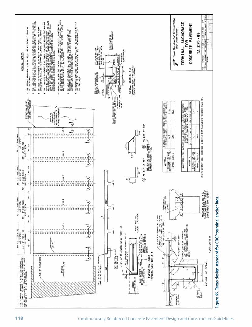
Continuousely Reinforced Concrete Pavement Design and Construction Guidelines118
Figu
re 6
5. T
exas
des
ign
stan
dard
for C
RCP
term
inal
anc
hor l
ugs.

May 2009 - DRAFT LAYOUT 119
Figu
re 6
6. T
exas
des
ign
stan
dard
for b
ridg
e ap
proa
ch s
lab
(she
et 1
of 2
).
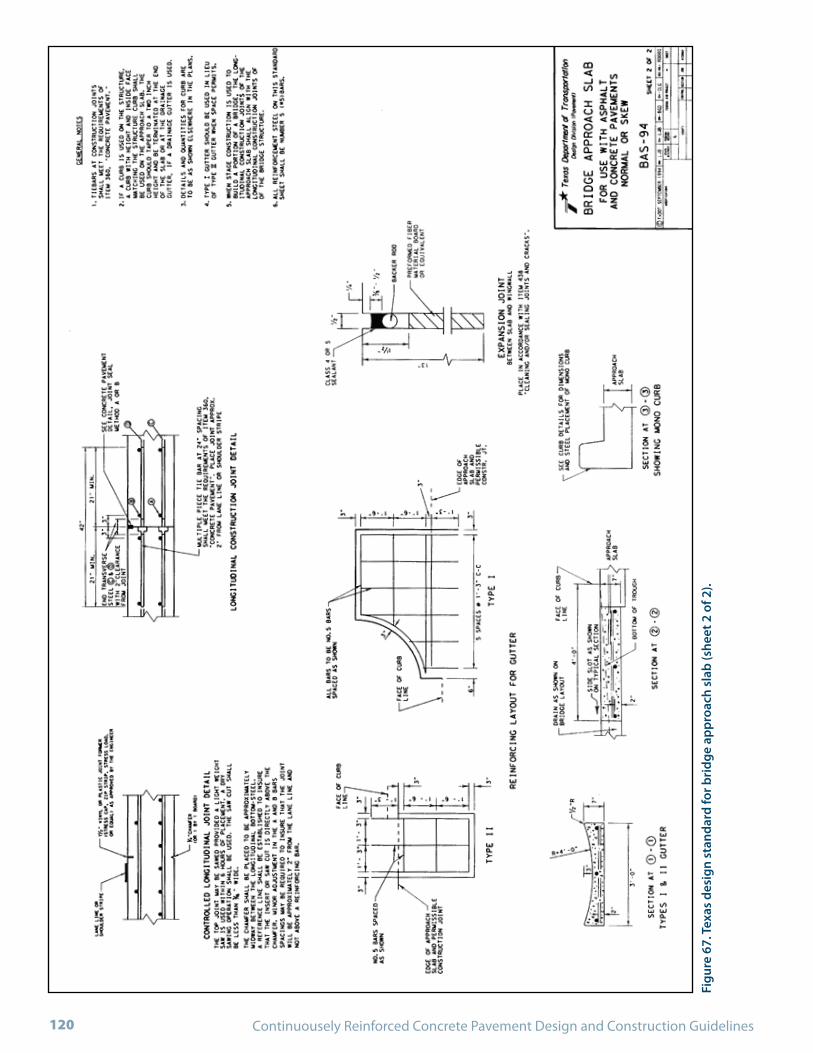
Continuousely Reinforced Concrete Pavement Design and Construction Guidelines120
Figu
re 6
7. T
exas
des
ign
stan
dard
for b
ridg
e ap
proa
ch s
lab
(she
et 2
of 2
).

May 2009 - DRAFT LAYOUT 121
Illinois DOT Design Standards

Continuousely Reinforced Concrete Pavement Design and Construction Guidelines122
Figu
re 6
8. Il
linoi
s de
sign
sta
ndar
d fo
r CRC
P ba
r rei
nfor
cem
ent.

May 2009 - DRAFT LAYOUT 123
Figu
re 6
9. Il
linoi
s de
sign
sta
ndar
d fo
r 24
ft (7
.2 m
) CRC
P w
ith w
ide
flang
e be
am tr
ansi
tion
join
t (sh
eet 1
of 2
).

Continuousely Reinforced Concrete Pavement Design and Construction Guidelines124
Figu
re 7
0. Il
linoi
s de
sign
sta
ndar
d fo
r 24
ft (7
.2 m
) CRC
P w
ith w
ide
flang
e be
am tr
ansi
tion
join
t (sh
eet 2
of 2
).

May 2009 - DRAFT LAYOUT 125
Figu
re 7
1. Il
linoi
s de
sign
sta
ndar
d fo
r bri
dge
appr
oach
pav
emen
t (sh
eet 1
of 4
).

Continuousely Reinforced Concrete Pavement Design and Construction Guidelines126
Figu
re 7
2. Il
linoi
s de
sign
sta
ndar
d fo
r bri
dge
appr
oach
pav
emen
t (sh
eet 2
of 4
).

May 2009 - DRAFT LAYOUT 127
Figu
re 7
3. Il
linoi
s de
sign
sta
ndar
d fo
r bri
dge
appr
oach
pav
emen
t (sh
eet 3
of 4
).

Continuousely Reinforced Concrete Pavement Design and Construction Guidelines128
Figu
re 7
4. Il
linoi
s de
sign
sta
ndar
d fo
r bri
dge
appr
oach
pav
emen
t (sh
eet 4
of 4
).

May 2009 - DRAFT LAYOUT 129
Composite PavementsRigid composite pavements are defined as a concrete pavement (commonly CRCP) overlaid with a thin HMA wearing course. Rigid composite pavements are not new in the US. In fact, many existing CRCP have been rehabili-tated with a HMA overlay to improve ride quality and skid resistance, and to provide additional structural support in the past. However, a stricter definition of rigid composite pavements includes an HMA overlay on a newly-placed concrete pavement. Use of this pavement type has recently become common practice in the Australia, the United King-dom, and other European countries. Their popularity has increased over the years as a means to provide both struc-tural and functional performance.(19,32) Benefits of compos-ite pavements that have been cited include:
Improved ride quality and skid resistance.•
Reduction in tire-pavement noise generation.•
Reduction in water infiltration.•
Possible reduction in corrosion of reinforcement in CRCP.•
Thermal insulation to prevent large temperature changes •in the CRCP.
In the UK, a HMA surfacing of at least 4 in (100 mm) is commonly used on top of what is termed a Continuously Reinforced Concrete Roadbase (CRCR). Overlays are scheduled at later stages during the pavement life. Rigid composite pavements are commonly designed for a 40-year life. Transverse reinforcement in the CRCR is required for ease and consistency of construction. Typical designs range from 6 to 10 in (150 to 240 mm) of CRCR and 4 in (100 mm) of HMA surfacing.(19) A minimum of 1.2 in (30 mm)
of wearing course is allowed in the UK on top of the CRCP. If a 4-in (100-mm) wearing course is used, a reduction in thickness of the CRCR is allowed. The structural contribu-tion and thermal insulation provided by the wearing course is accounted for in the CRCR thickness design.
Porous asphalt (PA) can be used as the surface course on CRCR. However, 2 in (50 mm) of PA surface course on top of 3.5 in (90 mm) binder course are required, otherwise, 2 in (50 mm) of PA on top of 2.4 (60 mm) of binder course is allowed as long as the CRCR is increased in thickness by 4 in (10 mm). When a PA surface course is used, it is modi-fied with a polymer or fiber additive.(19) While 0.6% of longitudinal reinforcement with #5 (16 mm) bars on CRCP without wearing course is specified in the UK, 0.4% with #4 (12 mm) bars is allowed for CRCR with a minimum of 100 mm (4 in) asphalt surface course.
Transverse reinforcement is typically specified with 0.5 in (12 mm) diameter deformed bars at 24 in (600 mm) spacings. Although a separation membrane (bond breaker) is used for jointed pavements, this layer is omitted from CRCR to provide a higher level of friction between the con-crete slab and the base. A layer with uniform properties such as a lean concrete or asphalt base is recommended under the CRCR. Whenever a 1.2-in (30-mm) thin wearing course is used, a bond coat is specified to ensure adhesion between the CRCR and this layer.(19)
It is important to note that while composite pavements provide one solution to improving ride quality and reduc-ing tire-pavement noise, other treatments such as diamond grinding can provide similar benefits for CRC pavement. Diamond grinding may in fact be a more economical solu-tion for improving functional characteristics of new and existing CRCP.


APPENDIX B:
AASHTO-86/93 GUIDE REINFORCEMENT DESIGN

Continuousely Reinforced Concrete Pavement Design and Construction Guidelines132

May 2009 - DRAFT LAYOUT 133
Longitudinal Reinforcement Design InputsThe inputs required in this procedure include:
Concrete tensile strength, • ft
Concrete CTE, • c
Concrete shrinkage at 28 days, • z
Reinforcing bar diameter, •
Steel CTE, • s
Design temperature drop, • LHD TTT −=∆ , and
Wheel load tensile stress, • s
Concrete Tensile StrengthThe concrete tensile strength determined through the ASTM C 496 or AASHTO T 198 splitting tensile test performed at 28 days is used in this procedure. A correlation of 86% of the third-point loading flexural strength used for thickness design may be assumed to determine the concrete tensile strength.
Concrete Coefficient of Thermal ExpansionTable 7 provides typical values of CTE for concrete made with different aggregate types. This information is derived from “Mass Concrete for Dams and Other Massive Struc-tures,” Proceedings, Journal of the American Concrete Institute, Vol. 67, April 1970, as referenced in AASHTO, 1993.(5)
Concrete Drying ShrinkageValues for 28-day concrete shrinkage as a function of split-ting tensile strength may be obtained from Table 8.
Table 7. Typical CTE for concrete made with common ag-gregate types.
Aggregate Type Concrete CTE x 10-6 in/in/ºF (m/m/ºC)
Quartz 6.6 (11.9)
Sandstone 6.5 (11.7)
Gravel 6 (10.8)
Granite 5.3 (9.5)
Basalt 4.8 (8.6)
Limestone 3.8 (6.8)
Table 8. Approximate relationship between shrinkage and indirect tensile strength of concrete.(5)
Indirect Tensile Strengthpsi (MPa)
Shrinkagein/in (m/m)
300 (2.07) or less 0.00080
400 (2.76) 0.00060
500 (3.45) 0.00045
600 (4.14) 0.00030
700 (4.83) or greater 0.00020
Reinforcing Bar DiameterTypical bar sizes used in CRCP range from # 4 (0.5 in) to # 7 (0.875 in) [#13 (13 mm) to # 22 (22 mm)].
Steel Coefficient of Thermal ExpansionA steel CTE of 5 ± 10-6 in/in/ºF (9 ± 10-6 m/m/ºC) is recommended for longitudinal reinforcement design unless information on the steel CTE is available.
Design Temperature DropThe design temperature drop is determined based on the average concrete curing temperature after placement and the lowest temperature of the year expected in the region where the CRCP will be constructed. The guidance provided in Section 3.5 may be used for this purpose.
Wheel Load Tensile StressWheel load tensile stresses due to construction traffic dur-ing the early age may impact the crack spacing pattern and are therefore accounted for in longitudinal reinforcement design. The wheel load stress may be obtained from Figure 75 as a function of the design slab thickness, magnitude of wheel load, and effective k-value.
Longitudinal Reinforcement Design ProcedureThe AASHTO-86/93 Guide includes design of the longi-tudinal reinforcement based on a desirable range of crack spacing, maximum crack width, and maximum steel stress.
Longitudinal reinforcement is designed to meet the follow-ing three criteria:
1. Amount of reinforcement required to produce desir-able crack spacings. Recommended crack spacings to

Continuousely Reinforced Concrete Pavement Design and Construction Guidelines134
minimize potential for development of punchouts and spalling range between 3.5 and 8 ft (1.1 and 2.4 m).
2. Amount of reinforcement required to keep transverse cracks tightly closed. Maximum allowable crack widths applicable to this procedure should not exceed 0.04 in (1.0 mm) to prevent spalling and water infiltration (although better practices would limit this to 0.02 in (0.5 mm).
3. Amount of reinforcement required to keep reinforce-ment stresses within allowable levels. Keeping the steel
Figure 75. Chart for estimating wheel load tensile stress.
(1 in = 25.4 mm, 1 psi = 6.98 KPa, 1 pci = 0.271 MPa/m)
working at an acceptable stress level minimizes fracture of the steel or excessive yield that may lead to wide cracks with poor load transfer efficiency. Maximum allowable working stress for steel Grade 60 (Grade 420) recommended by AASHTO-86/93 as a function of indirect tensile concrete strength and reinforcing bar diameter is provided in Table 9.
With the design inputs obtained following the guidelines in Section 3, and the above limiting criteria, the longitudinal reinforcement design is accomplished following the proce-dure described below:

May 2009 - DRAFT LAYOUT 135
The amount of longitudinal steel reinforcement to satisfy •each limiting criterion is obtained using the design charts in Figure 76, Figure 77, and Figure 78. The minimum required steel percentage (Pmin) corresponds to the largest obtained among the crack spacing of 8 ft (2.4 m), crack width, and steel stress criteria. The maximum required steel percentage (Pmax) corresponds to the crack spacing of 3.5 ft (1.1 m). The design charts are accessed by drawing a
continuous line intersecting the selected design values on the various scales to determine the percent steel. (In some cases, it may be necessary to extend the turning lines to the top or bottom of the chart.)
If Pmax is greater than or equal to P• min, proceed to the next step. However, if Pmax is less than Pmin, the design is considered unsatisfactory and revision of the selected inputs should be made until Pmax is greater than Pmin.
Figure 76. Minimum percent longitudinal reinforcement to satisfy crack width criterion.
(1 in = 25.4 mm, 1 psi = 6.98 KPa)
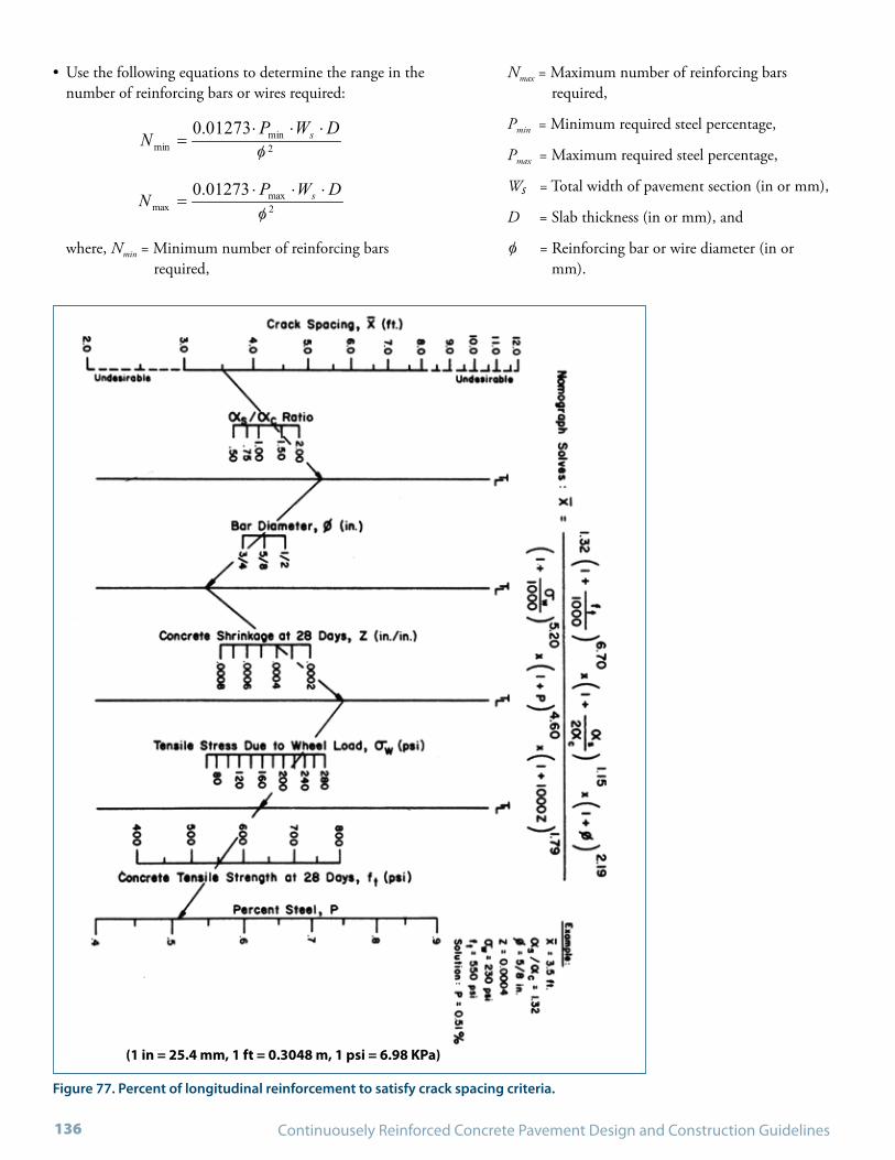
Continuousely Reinforced Concrete Pavement Design and Construction Guidelines136
Use the following equations to determine the range in the •number of reinforcing bars or wires required:
where, Nmin = Minimum number of reinforcing bars required,
Nmax = Maximum number of reinforcing bars required,
Pmin = Minimum required steel percentage,
Pmax = Maximum required steel percentage,
Ws = Total width of pavement section (in or mm),
D = Slab thickness (in or mm), and
= Reinforcing bar or wire diameter (in or mm).
Figure 77. Percent of longitudinal reinforcement to satisfy crack spacing criteria.
(1 in = 25.4 mm, 1 ft = 0.3048 m, 1 psi = 6.98 KPa)
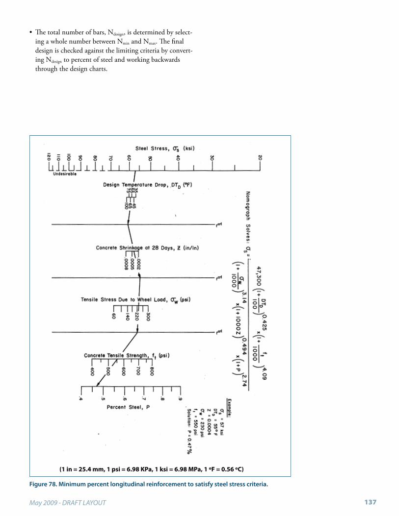
May 2009 - DRAFT LAYOUT 137
The total number of bars, N• design, is determined by select-ing a whole number between Nmin and Nmax. The final design is checked against the limiting criteria by convert-ing Ndesign to percent of steel and working backwards through the design charts.
Figure 78. Minimum percent longitudinal reinforcement to satisfy steel stress criteria.
(1 in = 25.4 mm, 1 psi = 6.98 KPa, 1 ksi = 6.98 MPa, 1 ºF = 0.56 ºC)


APPENDIX C:
GLOSSARY

Continuousely Reinforced Concrete Pavement Design and Construction Guidelines140

May 2009 - DRAFT LAYOUT 141
Aggregate – Granular material, such as sand, gravel, crushed stone, crushed hydraulic-cement concrete, or iron blast fur-•nace slag, used with a hydraulic cementing medium to produce either concrete or mortar.
Aggregate Interlock• – The projection of aggregate particles or portion of aggregate particles from one side of a joint or crack in concrete into recesses in the other side of the joint or crack to effect load transfer in compression and shear and maintain mutual alignment.
Air Content – The amount of air in mortar or concrete, exclusive of pore space in the aggregate particles, usually expressed •as a percentage of total volume of mortar or concrete.
Air Void – A space in cement paste, mortar, or concrete filled with air; an entrapped air void is characteristically 0.4 in (1 •mm) or more in size and irregular in shape; an entrained air void is typically between 3.93 x 10⁻⁴ and 0.39 in (10 m and 1 mm) in diameter and spherical (or nearly so).
Air Entraining – The capabilities of a material or process to develop a system of minute bubbles of air in cement paste, •mortar, or concrete during mixing.
Alkali-Aggregate Reaction (AAR) – Chemical reaction in mortar or concrete between alkalis (sodium and potassium) •released from cement or from other sources, and certain compounds present in the aggregates; under certain conditions, harmful expansion of the concrete or mortar may be produced.
Alkali-Silica Reaction (ASR) – The reaction between the alkalis (sodium and potassium) in cement and certain siliceous •rocks or minerals, such as opaline chert, strained quartz, and acisic volcanic glass, present in some aggregates; the products of the reaction may cause abnormal expansion and cracking of concrete in service.
ACPA – American Concrete Pavement Association•
Area of Steel – The cross-sectional area of the reinforcing bars in or for a given concrete cross section.•
ASTM – American Society for Testing and Materials •
Bar Chair – An individual supporting device used to support or hold reinforcing bars in proper position to prevent dis-•placement before or during concreting.
Bar Spacing – The distance between parallel reinforcing bars, measured center to center of the bars perpendicular to their •longitudinal axis.
Blanking Band – A plastic scale, or computer-generated scale, 1.7 in (43 mm) wide and 21.12 in (0.5 m) long representing •a length of 0.1 mi (161 m) on a profilograph trace. The opaque blanking strip, running the length of the scale and located at its midpoint, covers the profile trace. Typically, a bandwidth of 0.0 to 0.2 in (0 to 5 mm) is used.
Bleeding – The self-generated flow of mixing water within, or its emergence from, freshly placed concrete or mortar.•
Bond – The adhesion of concrete or mortar to reinforcement or other surfaces against which it is placed; the adhesion of •cement paste to aggregate.
Bond Strength – Resistance to separation of mortar and concrete from reinforcing steel and other materials with which it •is in contact; a collective expression for all forces such as adhesion, friction due to shrinkage, and longitudinal shear in the concrete engaged by the bar deformations that resist separation.
Bond Stress – The force of adhesion per unit area of contact between two surfaces such as concrete and reinforcing steel or •any other material such as foundation rock.
Burlap – A coarse fabric of jute, hemp, or less commonly flax, for use as a water-retaining cover for curing concrete sur-•faces; also called Hessian.
Burlap Drag – Surface texture achieved by trailing moistened coarse burlap from a device that allows control of the time •and rate of texturing.

Continuousely Reinforced Concrete Pavement Design and Construction Guidelines142
California Profilograph – Rolling straight edge tool used for evaluating pavement profile (smoothness) consisting of a 25-ft •(7.6-m) frame with a sensing wheel located at the center of the frame that senses and records bumps and dips on graph paper or in a computer.
Coefficient of Thermal Expansion (CTE) – Change in linear dimension per unit length or change in volume per unit vol-•ume per degree of temperature change.
Compressive Strength – The measured resistance of a concrete or mortar specimen to axial loading; expressed as pounds •per square inch (psi) of cross-sectional area.
Concrete – See Portland Cement Concrete.•
Concrete Overlay – Overlay of new concrete placed onto existing concrete pavement; it is unbonded when an interlayer is •used between the new and old concrete surface to separate them; it is bonded if there is no interlayer.
Consistency – The relative mobility or ability of fresh concrete or mortar to flow. The usual measures of consistency are •slump or ball penetration for concrete and flow for mortar.
Consolidation – The process of inducing a closer arrangement of the solid particles in freshly mixed concrete or mortar •during placement by the reduction of voids, usually by vibration, centrifugation, tamping, or some combination of these actions; also applicable to similar manipulation of other cementitious mixtures, soils, aggregates, or the like.
Construction Joint – A joint made necessary by a prolonged interruption in the placing of concrete.•
Continuously Reinforced Concrete Pavement (CRCP) – Portland cement concrete pavement with no transverse joints and •containing longitudinal steel in an amount designed to ensure holding shrinkage cracks tightly closed. Joints exist only at construction joints and on-grade structures.
CRSI – Concrete Reinforcing Steel Institute.•
Curing – The maintenance of a satisfactory moisture content and temperature in concrete during its early stages so that •desired properties may develop.
Curing Blanket – A built-up covering of sacks, matting, Hessian, straw, waterproof paper, or other suitable material placed •over freshly finished concrete. See also Burlap.
Curing Compound – A liquid that can be applied as a coating to the surface of newly placed concrete to retard the loss •of water or, in the case of pigmented compounds, also to reflect heat so as to provide an opportunity for the concrete to develop its properties in a favorable temperature and moisture environment.
Deformed Bar – A reinforcing bar with a manufactured pattern of surface ridges that provide a locking anchorage with •surrounding concrete.
Drainage – The interception and removal of water from, on, or under an area or roadway; the process of removing surplus •ground or surface water artificially; a general term for gravity flow of liquids in conduits.
Durability – The ability of concrete to remain unchanged while in service; resistance to weathering action, chemical attack, •and abrasion.
Early Strength – Strength of concrete developed soon after placement, usually during the first 72 hours.•
FHWA – Federal Highway Administration•
Final Set – A degree of stiffening of a mixture of cement and water greater than initial set, generally stated as an empirical •value indicating the time in hours and minutes required for a cement paste to stiffen sufficiently to resist to an established degree, the penetration of a weighted test needle; also applicable to concrete and mortar mixtures with use of suitable test procedures. See also Initial Set.
Finishing – Leveling, smoothing, compacting, and otherwise treating surfaces of fresh or recently placed concrete or mortar •to produce desired appearance and service.

May 2009 - DRAFT LAYOUT 143
Fixed Form Paving – A type of concrete paving process that involves the use of fixed forms to uniformly control the edge •and alignment of the pavement.
Floating – Process of using a tool, usually wood, aluminum, or magnesium, in finishing operations to impart a relatively •even but still open texture to an unformed fresh concrete surface.
Grooving – The process used to cut slots into a concrete pavement surface to provide channels for water to escape beneath •tires and to promote skid resistance.
Hairline Cracking – Barely visible cracks in random pattern in an exposed concrete surface which do not extend to the full •depth or thickness of the concrete, and which are due primarily to drying shrinkage.
Hardening – When cement is mixed with enough water to form a paste, the compounds of the cement react with water •to form cementitious products that adhere to each other and to the intermixed sand and stone particles and become very hard. As long as moisture is present, the reaction may continue for years, adding continually to the strength of the mixture.
Honeycomb – Concrete that, due to lack of the proper amount of fines or vibration, contains abundant interconnected •large voids or cavities; concrete that contains honeycombs was improperly consolidated.
Initial Set – A degree of stiffening of a mixture of cement and water less than final set, generally stated as an empirical value •indicating the time in hours and minutes required for cement paste to stiffen sufficiently to resist to an established degree the penetration of a weighted test needle; also applicable to concrete or mortar with use of suitable test procedures.
Jointed Plain Concrete Pavement (JPCP) – Pavement containing enough joints to control all natural cracks expected in •the concrete; steel tiebars are generally used at longitudinal joints to prevent joint opening, and dowel bars may be used to enhance load transfer at transverse contraction joints depending upon the expected traffic.
Jointed Reinforced Concrete Pavement (JRCP) – Pavement containing some joints and embedded steel mesh reinforce-•ment (sometimes called distributed steel) to control expected cracks; steel mesh is discontinued at transverse joint locations
Keyway – A recess or groove in one lift or placement of concrete which is filled with concrete of the next lift, giving shear •strength to the joint.
Load Transfer Efficiency – The ability of a joint or crack to transfer a portion of a load applied on side of the joint or crack •to the other side of the joint or crack.
Longitudinal Cracking – Pavement cracking predominantly parallel to the direction of traffic.•
Longitudinal Joint – A joint placed parallel to the long dimension of the pavement to control longitudinal cracking.•
Longitudinal Reinforcement – Reinforcement essentially parallel to the long axis of a concrete member or pavement.•
Longitudinal Tine – Surface texture achieved by a hand held or mechanical device equipped with a rake-like tining head •that moves in a line parallel to the pavement centerline.
Longitudinal Profile – The perpendicular deviations of the pavement surface from an established reference parallel to the •lane direction, usually measured in the wheel tracks.
Maximum Size Aggregate – The largest size aggregate particles present in sufficient quantity to affect properties of a con-•crete mixture.
Mechanistic-Empirical – A design philosophy or approach wherein classical mechanics (physics) is used in conjunction •with empirically derived relationships to accomplish the design objectives.
Membrane Curing – A process that involves either liquid sealing compound (e.g., bituminous and paraffinic emulsions, •coal tar cut-backs, pigmented and non-pigmented resin suspensions, or suspensions of wax and drying oil) or non-liquid protective coating (e.g., sheet plastics or “waterproof” paper), both of which types function as films to restrict evaporation of mixing water from the fresh concrete surface.
Continuousely Reinforced Concrete Pavement Design and Construction Guidelines144
Modulus of Elasticity (E) – The modulus of any material is a measure of the stress-strain behavior of the material.•
Modulus of Rupture – An indicator of tensile bending strength of concrete, is the maximum tensile stress at the bottom at •rupture during a flexural test of a simply supported concrete beam.
Modulus of Subgrade Reaction (k) – Westergaard’s modulus of subgrade reaction for use in rigid pavement design (the •load in pounds per square inch on a loaded area of the roadbed soil or subbase divided by the deflection in inches of the roadbed soil or subbase, psi/ in.).
Moisture Content of Aggregate – The ratio, expressed as a percentage, of the weight of water in a given granular mass to •the dry weight of the mass.
Paving Train – An assemblage of equipment designed to place and finish a concrete pavement. •
Pavement Condition – A quantitative representation of pavement distress at a given point in time.•
Pavement Management – The effective and efficient direction of the various activities involved in providing and sustaining •pavements at a condition acceptable to the traveling public at the lowest life-cycle-cost.
Pavement Performance – Measure of accumulated service provided by a pavement (i.e., the adequacy with which it fulfills •it purpose). Often referred to the record of pavement condition or serviceability over time or with accumulated traffic.
Pavement Rehabilitation – Work undertaken to extend the service life of an existing facility. This includes placement of •additional surfacing material and/or other work necessary to return an existing roadway, including shoulders, to a condi-tion of structural or functional adequacy. This could include the complete removal and replacement of a portion of the pavement structure.
Pavement Structure – A combination of subbase, base course, and surface course placed on a subgrade to support the traf-•fic load and distribute it to the roadbed.
PCA – Portland Cement Association •
Percent Fines – Amount, expressed as a percentage, of material in aggregate finer than a given sieve, usually the No. 200 •(0.075 mm) sieve; also, the amount of fine aggregate in a concrete mixture expressed as a percent by absolute volume of the total amount of aggregate.
Performance-Related Specifications (PRS) – Specifications that describe the desired levels of key materials and construc-•tion quality characteristics that have been found to correlate with fundamental engineering properties that predict per-formance. These characteristics (for example, strength of concrete cores) are amenable to acceptance testing at the time of construction.
Permeable Subbase – Layer consisting of crushed aggregates with a reduced amount of fines to promote drainage and stabi-•lized with Portland cement or bituminous cement.
Placement, Concrete – The process of placing and consolidating concrete; a quantity of concrete placed and finished dur-•ing a continuous operation.
Portland Cement Concrete (PCC) – A composite material that consists essentially of a binding medium (Portland cement •and water) within which are embedded particles or fragments of aggregate, usually a combination of fine aggregate course aggregate.
Profile Index – Smoothness qualifying factor determined from profilograph trace. Calculated by dividing the sum of the •total counts above the blanking band for each segment by the sum of the segment length.
Punchout – In continuously reinforced concrete pavement, the area enclosed by two closely spaced (less than 3 ft or 1m) •transverse cracks, a short longitudinal crack, and the edge of the pavement or longitudinal joint, when exhibiting spalling, shattering, or faulting. Also, area between Y cracks exhibiting this same deterioration.

May 2009 - DRAFT LAYOUT 145
Quality Assurance (QA) – Planned and systematic actions by an owner or his representative to provide confidence that •a product or facility meet applicable standards of good practice. This involves continued evaluation of design, plan and specification development, contract advertisement and award, construction, and maintenance, and the interactions of these activities.
Quality Control (QC) – Actions taken by a producer or contractor to provide control over what is being done and what is •being provided so that the applicable standards of good practice for the work are followed.
Random Cracking – Uncontrolled and irregular fracturing of a pavement layer.•
Reinforcement – Steel embedded in a rigid slab to resist tensile stresses and detrimental opening of cracks.•
Resilient Modulus – A standardized measurement of the modulus of elasticity of roadbed soil or other pavement material. •
Rideability – a subjective judgment of the comparative discomfort induced by traveling over a specific section of highway •pavement in a vehicle.
Sawcut – A cut in hardened concrete utilizing diamond or silicone-carbide blades or discs.•
Select Material – A suitable native material obtained from a specified source such as a particular roadway cut or borrow •area, of a suitable material having specified characteristics to be used for a specific purpose.
Setting of Cement – Development of rigidity of cement paste, mortar, or concrete as a result of hydration of the cement. •The paste formed when cement is mixed with water remains plastic for a short time. During this stage it is still possible to disturb the material and remix without injury, but as the reaction between the cement and water continues, the mass loses its plasticity. This early period in the hardening is called the “setting period,” although there is not a well-defined break in the hardening process.
Setting Time – The time required for a specimen of concrete, mortar or cement paste, prepared and tested under standard-•ized conditions, to attain a specified degree of rigidity.
Shrinkage Cracking – Cracking of a slab due to failure in tension caused by external or internal restraints as reduction in •moisture content develops.
Skid Resistance – A measure of the frictional characteristics of a surface.•
Slipform Paving – A type of concrete paving process that involves extruding the concrete through a machine to provide a •uniform dimension of concrete paving.
Slump – A measure of consistency of freshly mixed concrete, equal to the subsidence measured to the nearest ¼-inch of the •molded specimen immediately after removal of the slump cone.
Strength – A generic term for the ability of a material to resist strain or rupture induced by external forces. See also Com-•pressive Strength, Fatigue Strength, Flexural Strength, Shear Strength, Splitting Tensile Strength, Tensile Strength, Ultimate Strength, and Yield Strength.
Stress – Intensity of internal force (i.e., force per unit area) exerted by either of two adjacent parts of a body on the other •across an imagined plane of separation; when the forces are parallel to the plane, the stress is called shear stress; when the forces are normal to the plane the stress is called normal stress; when the normal stress is directed toward the part on which it acts it is called compressive stress; when it is directed away from the part on which it acts it is called tensile stress.
Strikeoff – To remove concrete in excess of that required to fill the form evenly or bring the surface to grade; performed •with a straightedged piece of wood or metal by means of a forward sawing movement or by a power operated tool appro-priate for this purpose; also the name applied to the tool. See also Screed and Screeding.
Surface Texture – Degree of roughness or irregularity of the exterior surfaces of aggregate particles or hardened concrete.•
Subgrade – The top surface of a roadbed upon which the pavement structure and shoulders are constructed.•

Continuousely Reinforced Concrete Pavement Design and Construction Guidelines146
Subgrade, Improved – Any course or courses of select or improved materials between the subgrade soil and the pavement •structure.
Tensile Strength – Maximum stress that a material is capable of resisting under axial tensile loading based on the cross-•sectional area of the specimen before loading.
Terminal Joint – Joint used in continuously reinforced concrete pavement at the transition to another pavement type or to •a bridge structure.
Tiebar – Deformed steel bar extending across a longitudinal joint in a rigid pavement to prevent separation of abutting •slabs.
Transverse Cracking – Pavement cracking predominantly perpendicular to the direction of traffic.•
Vibration – Energetic agitation of concrete produced by a mechanical oscillating device at moderately high frequency to •assist consolidation and compaction
Vibration, External – External vibration employs vibrating devices attached at strategic positions on the forms and is •particularly applicable to manufacture of precast items and for vibration of tunnel-lining forms; in manufacture of concrete products, external vibration or impact may be applied to a casting table.
Vibration, Internal – Internal vibration employs one or more vibrating elements that can be inserted into the concrete at •selected locations, and is more generally applicable to in-place construction.
Vibration, Surface – Surface vibration employs a portable horizontal platform on which a vibrating element is mounted. •
Vibrator – An oscillating machine used to agitate fresh concrete so as to eliminate gross voids, including entrapped air but •no entrained air, and produce intimate contact with form surfaces and embedded materials.
Water-Cement Ratio – The ratio of the amount of water, exclusive only of that absorbed by the aggregates, to the amount •of cement in a concrete or mortar mixture; preferably stated as a decimal by weight.

APPENDIX D:
REFERENCES


May 2009 - DRAFT LAYOUT 149
1 Ray, Gordon K., History and Development of Concrete Pavement Design, Journal of the Highway Division, Proceed-ings of the American Society of Civil Engineers, January 1964.
2 Associated Reinforced Bar Producers – CRSI, Design of Continuously Reinforced Concrete for Highways, 1981.
3 Concrete Reinforcing Steel Institute, The Illinois Experience, Case History Report No. 55, 2001.
4 Concrete Reinforcing Steel Institute, Summary of CRCP Design and Construction Practices in the US, Research Series No. 8, 2001.
5 American Association of State Highway and Transportation Officials, AASHTO Guide for Design of Pavement Struc-tures, Washington, D. C., 1993.
6 Tayabji, S. D., Zollinger, D. G., Korovesis, G. T., Stephanos, P. J., Gagnon, J. S. Performance of Continuously Rein-forced Concrete Pavements – Volume I: Summary of Practice and Annotated Bibliography. FHWA-RD-94-178, 1998.
7 Tayabji, S. D., Stephanos, P. J., Gagnon, J. S. and Zollinger, D. G. Performance of Continuously Reinforced Concrete Pavements: Volume II – Field Investigations of CRC Pavements. FHWA-RD-94-179, 1998.
8 Tayabji, S. D., Zollinger, D. G., Vederey, J. R. and Gagnon, J. S. Performance of Continuously Reinforced Concrete Pavements: Volume III – Analysis and Evaluation of Field Test Data. FHWA-RD-94-180, 1998.
9 Zollinger, D. G., Buch, N., Xin, D., and Soares, J. Performance of CRC Pavements: Volume VI – CRC Pavement Design, Construction and Performance. FHWA-RD-97-151, 1999.
10 Sriraman, S. and Zollinger, D. G. Performance of CRC Pavements: Volume IV – Resurfacings for CRC Pavements. FHWA-RD-98-100, 1999.
11 Gagnon, J. S., Zollinger, D. G, and Tayabji, S. D. Performance of Continuously Reinforced Concrete Pavements: Vol-ume V – Maintenance and Repair of CRC Pavements. FHWA-RD-98-101, 1998.
12 Zollinger, D. G. and Soares, J. (1999). Performance of CRC Pavements: Volume VII – Summary. FHWA-RD-98-102.
13 Tayabji, S. D., Selezneva, O. and Jiang, J. (1999). Preliminary Evaluation of LTPP Continuously Reinforced Concrete (CRC) Pavement Test Sections. FHWA-RD-99-086.
14 Selezneva, O.I., Zollinger, D., Darter, M., Mechanistic Analysis of Factors Leading to Punchout Development for Improved CRCP Design Procedures, Proceedings of the Seventh International Conference on Concrete Pavements, Orlando, Florida; September 2001.
15 Elfino, M., Ozyildirim, C., Steele, R., CRCP in Virginia, Lessons Learned, Proceedings of the Seventh International Conference on Concrete Pavements, Orlando, Florida; September 2001.
16 Wimsatt, A.J., Concrete Pavement Design and Construction Practices by the Texas DOT, Proceedings of the 5th Inter-national Conference on Concrete Pavement Design and Rehabilitation, Purdue, 1993.
17 Peshkin, D., Darter, M., The Construction and Performance of Concrete Pavements Reinforced with Flexarm, Pro-ceedings of the 5th International Conference on Concrete Pavement Design and Rehabilitation, Purdue, 1993.
18 Ayton, G.P., Concrete Highway Pavements in Australia, Proceedings of the 5th International Conference on Concrete Pavement Design and Rehabilitation, Purdue, 1993.
19 Design Manual for Roads and Bridges, Pavement Design, HD 26/01, United Kingdom, 2001.
20 Orval, L.H.J.G., Hazelzet, P.A., Van Den Boom, W.C., Continuously Reinforced Concrete Roadbases, 7th Interna-tional Symposium on Concrete Roads, Vienna, 1994.
21 Selezneva, O., Darter, M., Zollinger, D., Shoukry, S., Characterization of Transverse Cracking Spatial Variability Using LTPP Data for CRCP Design, paper submitted to the Transportation Research Board 82nd Annual Meeting, CD-ROM, 2002.

Continuousely Reinforced Concrete Pavement Design and Construction Guidelines150
22 McCullough, B. F., Abou-Ayyash, A., Hudson, W. R., and Randall, J. P. (1975). Design of Continuously Reinforced Concrete Pavements for Highways: Final Report. Research Project NCHRP 1-15. Prepared for Transportation Research Board National Cooperative Highway Research Program National Academy of Sciences.
23 McCullough, B.F., Dossey, T., Zollinger, D., Evaluation of the Performance of Texas Pavements Made with Different Coarse Aggregates, Texas Department of Transportation, Report No. TX-01/7-3925-1, October 2000.
24 McCullough, B.F., Ma, J.C.M., and Noble, C.S., Limiting Criteria for the Design of CRCP, Texas State Department of Highways and Public Transportation, Report No. FHWA/TX-79/21+177-17, August 1979.
25 Huang, Y. H., Pavement Analysis and Design. Prentice Hall. Englewood Cliffs, NJ. 1993.
26 Kohn, S.D., Tayabji, S., Perera, R.W., Wu, C., Achieving High Levels of Smoothness without Hindering Long Term Performance, Federal Highway Administration Interim Report, Contract DTFH61-01-C-00030, September 2002.
27 Sayers, M.W., Karamihas, S.M., The Little Book of Profiling, October 1997.
28 Grogg, Max G. and Smith, Kurt D., concrete Pavement Smoothness: Characteristics and Best Practices for Construc-tion, US Department of Transprotation, Federal Highway Administration, FHWA-IF-02-025, March 2002.
29 Guide for Mechanistic-Empirical Design of New and Rehabilitated Pavement Structures, Final Report, 1-37A, National Cooperative Highway Research Program, Transportation Research Board, National Research Council, March 2004.
30 American Concrete Pavement Association, The Concrete Pavement Restoration Guide, Technical Bulletin TB-020P, 1997.
31 Concrete Reinforcing Steel Institute, Using Soft Metric Reinforcing Bars in Non-Metric Construction Projects, Report No. 42, 1997.
32 Continuously Reinforced Concrete Pavements, Permanent International Association of Road Congresses, 1994.
33 Zollinger, D.G., McKneely, A., Murphy, J., Tang, T., Analysis of Field Monitoring Data of CRC Pavements Con-structed with Grade 70 Steel, Texas Department of Transportation, Report No. TX-99/4925-1, 1999.
34 Wimsatt, A.J., Concrete Pavement Design and Construction Practices by the Texas DOT, Proceedings of the 5th Inter-national Conference on Concrete Pavement Design and Rehabilitation, Purdue, 1993.
35 Aunis, J., Guérin, G., Positive Results Obtained from CRCP Projects in France (1988-1991), 7th International Sympo-sium on Concrete Roads, pp. 137-141, October 1994.
36 Peshkin, D. G., Darter, M.I., Aunis, J., The Construction and Performance of Concrete Pavements Reinforced with Flexarm, Proceedings of the 5th International Conference on Concrete Pavement Design and Rehabilitation, Purdue, 1993.
37 Choi, J. and Chen, H. L., Design Consideration of GFRP-Reinforced CRCP, Field Applications of FRP Reinforce-ment: Case Studies, ACI SP-215, pp.139-158, September 2003.
38 FRP rebar, on Emerging Construction Technologies, http://www.new-technologies.org/ECT/Civil/frprebar.htm, Accessed May 21, 2004.
39 Choi, Jeong-Hoon and Roger H. L. Chen. Design of Continuously Reinforced Concrete Pavements Using Glass Fiber Reinforced Polymer Rebars. Federal Highway Administration, FHWA-HRT-05-081, October 2005.
40 Yoder, E.J. and Witczak, M.W., Principles of Pavement Design, John Wiley and Sons, Inc., 1975.
41 Federal Highway Administration, Drainable Pavement Systems, Participant Notebook, Demonstration Project 87, Washington, D.C., 1992.

May 2009 - DRAFT LAYOUT 151
42 Yu, H.T., Khazanovich, L., Rao, S., Darter, M.I., Quintus, H.V., Guidelines for Subsurface Drainage Based on Perfor-mance, National Cooperative Highway Research Program Final Report 1-34, Transportation Research Board, National Research Council, 1999.
43 Heckel, L., Open-Graded Drainage Layers: Performance Problems Under Continuously Reinforced Concrete Pave-ments in Illinois, 6th International Conference on Concrete Pavement Design and Materials for High Performance, Purdue, 1997.
44 Smith, K.L., Gharaibeh, N.G., Darter, M.I., Life-Cycle Cost Analysis of Continuously Reinforced Concrete Pavement, Final Report, Concrete Reinforced Steel Institute, February 2004.
45 Pavement Design Manual, Texas Department of Transportation , March 2001.
46 Rasmussen, Robert O. R., Rozycki, D.K., Characterization and Modeling of Axial Slab-Support Restraint, Transporta-tion Research Record No. 1778, Transportation Research Board, National Research Council, Washington, D.C., 2001.
47 Darter, M.I., Hall, K.T., and Kuo, C.-M., Support Under Portland Cement Concrete Pavements, National Coopera-tive Highway Research Program Report 372, Transportation Research Board, National Research Council, Washington, D.C., 1995.
48 Schindler A.K., Concrete Hydration, Temperature Development, and Setting at Early-Ages, Doctoral Dissertation, University of Texas at Austin, 2002.
49 American Association of State Highway and Transportation Officials, Supplement to the AASHTO Guide for Design of Pavement Structures, Washington, D. C., 1998.
50 Hall, K.T., Darter, M.I., Hoerner, T.E., Khazanovich, L., LTPP Data Analysis Phase I: Validation of Guidelines for k Value Selection and Concrete Pavement Performance Prediction. Report FHWA-RD-96-198, Federal Highway Administration, 1997.
51 Portland Cement Association, Thickness Design for Concrete Highway and Street Pavements, EB.109.01P, Skokie, Ill., 1984.
52 Darter, M.I., Quintus, H.V., Jiang, Y.J., Owusu-Antwi, E.B., Killingsworth, B.M., Catalog of Recommended Pave-ment Design Features, Final Report, National Cooperative Highway Research Program, Transportation Research Board National Research Council, June 1997.
53 Selezneva, O., Rao, C., Darter, M., Zollinger, D., Khazanovich, L., Development of a Mechanistic-Empirical Struc-tural Design Procedure for Continuously Reinforced Concrete Pavements, CD-ROM Proceedings of the Transporta-tion Research Board 83rd Annual Meeting, Washington, D.C., January 2004.
54 Ruiz, J.M., Rasmussen, R.O, Chang, G.K., Dick, J.C., Nelson, P.K., Ferragut, T.R., Computer-Based Guidelines for Concrete Pavements, Federal Highway Administration, FHWA-HRT-04-121, October 2004.
55 Won, M., Hankins, K., McCullough, B.F., Mechanistic Analysis of Continuously Reinforced Concrete Pavements Considering Material Characteristics, Variability, and Fatigue, Texas State Department of Highways and Public Trans-portation, Report No. FHWA/TX-92+1169-2, March 1991.
56 Federal Highway Administration, Continuously Reinforced Concrete Pavement, Technical Advisory T 5080.14, June 5, 1990.
57 Otero, M.A., McCullough, B.F., and Hankins, K., Monitoring of Siliceous River Gravel and Limestone Continuously Reinforced Concrete Pavement Test Sections in Houston 2 Yeas After Placement, and Development of a Crack Width Model for the CRCP-7 Program, Texas Department of Transportation, Research Report FHWA/TX-92+1244-4, March 1992.
58 Concrete Reinforcing Steel Institute, Design and Construction, Continuously Reinforced Concrete Pavement, Con-tinuously Reinforced Pavement Group, Chicago, Illinois, 1968.

Continuousely Reinforced Concrete Pavement Design and Construction Guidelines152
59 Lepper, H.A., Kim, J.B., Tests of Reinforcement Splices for Continuously Reinforced Concrete Pavement, Highway Research Record No. 60, Highway Research Board, National Academy of Sciences, National Research Council, Wash-ington, D.C., 1964.
60 Verhoeven, K., Cracking and Corrosion in Continuously Reinforced Concrete Pavements, Proceedings of the 5th International Conference on Concrete Pavement Design and Rehabilitation, Purdue, 1993.
61 Highways for LIFE, US Department of Transportation, Federal Highway Administration, http://www.fhwa.dot.gov/hfl/successstory.cfm?id=11, last accessed June 27, 2006.
62 McCullough, B.F., Herber, F., A Report on Continuity Between a Continuously Reinforced Concrete Pavement and a Continuous Slab Bridge, Report No. 39-3, Texas Highway Department, August 1966.
63 Griffiths, Steve, Bowmaker, Geoff, Bryce, Chris, and Bridge, Russell, Design and Construction of Seamless Pavement on Westlink M7, Sydney, Australia, 8th International Conference on Concrete Pavements, p. 21-38, International Society for Concrete Pavements, Colorado Springs, Colorado, USA, August 14-18, 2005.
64 Walls J. and Smith, M.R., Life-Cycle Cost Analysis in Pavement Design - Interim Technical Bulletin, Federal Highway Administration, Publication No. FHWA-SA-98-079, September 1998.
65 Smith, K. D., H. T. Yu and D. G. Peshkin. Portland Cement Concrete Overlays: State of the Technology Synthesis. FHWA-IF-02-045. April 2002.
66 Von Neumann, J., and Morgenstern. Theory of Games and Economic Behavior, 3rd ed., Princeton, NJ, Princeton University Press, 1953.
67 Jung, Younsu, D.G. Zollinger, and S.D. Tayabji, Best Practices of Concrete Pavement Transition Design and Construc-tion, Research Report 0-5320-1, Texas Transportation Institute, College Station, Texas, October 2006.
68 Concrete Reinforcing Steel Institute, “Continuous Reinforcement Makes a Good Pavement Better”.
69 Dhamrait, J.S. and R.K. Taylor. Behavior of Experimental CRC Pavements in Illinois, Technical Report No. FHWA-IL-PR-82, Illinois DOT, 1979.
70 Zollinger, D.G., N. Buch, D. Xin, and J. Soares. Performance of CRC Pavements. Volume 6 – CRC Pavement Design, Construction, and Performance, Report No. FHWA-RD-97-151, 1998.
71 McCullough, B.F. and T. Dossey. “Controlling Early-Age Cracking in Continuously Reinforced Concrete Pavement: Observations from 12 Years of Monitoring Experimental Test Sections in Houston, Texas,” In Transportation Research Record 1684, TRB, 1999.
72 Portland Cement Association, “Subgrade and Subbase for Concrete Pavements,” 1975.
73 Gharaibeh, N.G., M.I. Darter, and L.B. Heckel. “Field Performance of Continuously Reinforced Concrete Pavement in Illinois,” In Transportation Research Record 1684, TRB, 1999.
74 Parrott, L.J. “Moisture Profiles in Drying Concrete,” Advances in Cement Research, Vol. 1, No. 3, July 1988.
75 ERES Consultants, Inc. Pavement Subsurface Drainage Design—Reference Manual, Washington DC: Federal High-way Administration, 1999.
76 Concrete Reinforcing Steel Institute, “Using Soft Metric Reinforcing Bars in Non-Metric Construction Projects,” Report No. 42, 1997.
77 Zollinger, D.G., and E.J. Barenberg. Continuously Reinforced Pavements: Punchouts and Other Distresses and Implications for Design, Project IHR - 518, Illinois Cooperative Highway Research Program, University of Illinois at Urbana-Champaign, March 1990.

May 2009 - DRAFT LAYOUT 153
78 McCullough, B.F., A.A. Ayyash, W.R. Hudson, and J.P. Randall. “Design of Continuously Reinforced Concrete Pave-ments for Highways,” NCHRP 1-15, Center for Highway Research, The University of Texas at Austin, August 1975.
79 Darter, M.I. Report on the 1992 US Tour of European Concrete Highways, Report FHWA-SA-93-012, Federal High-way Administration, 1992.
80 Simpson, A.L., Rauhut, J.B., Jordahl, P.R., Owsusu-Antwi, E., Darter, M.I., and R. Ahmad. Sensitivity Analysis for Selected Pavement Distresses, Report SHRP-P-393, Strategic Highway Research Program, 1994.
81 Concrete Reinforcing Steel Institute, “Summary of CRCP Design and Construction Practices in the US”, Report No. 8, 2001.
82 Zwerneman, F.J., R.C. Donahey, H.S. Syed, and S.R. Gunna. “Cracking of Concrete Pavement Continuously Rein-forced with Epoxy-Coated Steel,” ACI Structural Journal, Vol. 92, No. 6, November-December 1975, pp 668-678.
83 Tayabji, S.D., P.J. Stephanos, and D.G. Zollinger. “Nationwide Field Investigation of Continuously Reinforced Con-crete Pavements,” In Transportation Research Record 1482, TRB, 1995.
84 Tang, T., D.G. Zollinger, and B.F. McCullough. “Field Tests and Analyses of Concrete Pavement in Taxarkana and La Porte, Texas,” Research Report 1244-7, Texas Transportation Institute, Texas A&M University, College Station, Texas, October 1996.
85 Federal Highway Administration, “Continuously Reinforced Concrete Pavement,” Technical Advisory, T 5080.14, Federal Highway Administration, June 1990.
86 Darter, M.I., H. Von Quintus, Y.J. Jiang, E.B. Owusu-Antwi, and B.M. Killingsworth.. Catalog of Recommended Pavement Design Features. NCHRP Final Report Project 1-32. Washington, DC, 1997.
87 Altobat, S.A. and D.A. Lange. “Early Age Stresses and Creep-Shrinkage Interaction of Restrained Concrete” Federal Aviation Administration DOT 95-C-001 and Center of Excellence for Airport Technology at the University of Illinois at Urbana-Champaign, COE Report No. 14. 2001.
88 American Association of State Highway and Transportation Officials, Standard Specifications for Transportation Mate-rials and Methods of Sampling and Testing, Part II Tests, Washington, DC: American Association of State Highway and Transportation Officials, 1993.
89 Concrete Reinforcing Steel Institute, “Continuously Reinforced Concrete Pavement for Highways, CRC Construction Manual,” Concrete Reinforcing Steel Institute (CRSI), 1983.
90 Tymkowicz, Shane and Robert F. Steffes. “Vibration Study for Consolidation of Portland Cement Concrete” Research report number MLR9504, Iowa Department of Transportation, Materials Department, 1995.
91 Kuemmel, D.A., R.C. Sontag, J.A. Crovetti, Y. Becker, J.R. Jaeckel, and A. Satanovasky, “Noise and Texture on con-crete Pavements – Results of a Multi-State Study,” Report No. WI/SPR-08-99, Marquette University. 2000.
92 Grogg, M.G. and K. D. Smith. concrete Pavement Smoothness: Characteristics and Best Practices for Construction, Contract No. DTFH61-01-P-00290, 2001.
93 American Concrete Pavement Association, “Stitching Concrete Pavement Cracks and Joints,” SR903P, 2001.
94 Transportation Research Board, “Design of Terminals for Rigid Pavements to Control End Movements: State of the Art,” Special Report 173. National Academy of Sciences. Washington, D.C., 1977.
95 LaCoursiere, S.A., M.I. Darter, and S.A. Smiley. Construction of CRCP Pavement in Illinois, Technical Report FHWA-IL-UI-172, University of Illinois and Illinois DOT, 1978.
96 Federal Highway Administration, “Paved Shoulders,” Technical Advisory, T 5040.29, 1990.

Continuousely Reinforced Concrete Pavement Design and Construction Guidelines154
97 Portland Cement Association, “Design of Concrete Mixtures,”, 1979.
98 Concrete Reinforcing Steel Institute, “Field Inspection of Reinforcing Bars”, Engineering Data Report No. 54, 2004.
99 Transportation Research Board, “Lime Stabilization—Reactions, Properties, Design, and Construction,” State of the Art Report 5, 1987.
100 Transportation Research Board, “Lime-Fly Ash-Stabilized Bases and Subbases,” NCHRP Synthesis No. 37, 1976.
101 Asphalt Institute, “A Basic Asphalt Emulsion Manual,” Manual Series No. 19.
102 Holtz, R.D., Christopher, B.R., and Berg, R.R., Geosynthetic Design and Construction Guidelines, Participant Note-book, NHI Course No. 13213, FHWA Publication No. FHWA HI-95-038 (revised), Federal Highway Administra-tion, 1998.
103 Roberts, F.L., P.S. Kandhal, E.R. Brown, D.Y. Lee, T.W. Kennedy, Hot Mix Asphalt Materials, Mixture Design, And Construction, Second Edition, NAPA Education Foundation, Lanham, Maryland, 1996.
104 Christory, J. P. “Assessment of PIARC Recommendations on the Combatting of Pumping in Concrete Pavements,” Sixth International Symposium on Concrete Roads. Madrid, Spain, 1990.
105 Permanent International Association of Road Congresses, “Combating Concrete Pavement Slab Pumping by Interface Drainage and Use of Low Erodability Materials: State of the Art and Recommendations,” Permanent International Association of Road Congresses, Paris, France, 1987.
106 Birmann, D. “Erosion of Cement Treated Subbases Below Concrete Pavement,” Theme III: Pavement Performance and Evaluation, Proceedings from the 8th International Symposium on Concrete Roads, Lisbon, Portugal, 1998.
107 Hoerner, T. E., M. I. Darter, L. Khazanovich, L. Titus-Glover, and K. L. Smith, “Improved Prediction Models for con-crete Pavement Performance-Related Specifications, “ Volume I: Final Report, FHWA-RD-00-130, Federal Highway Administration, 2000.
108 Roman, R. J. and M. I. Darter, “Pavement Distress Study I-77, Fairfield and Chester Counties, South Carolina,” Tech-nical Report submitted to South Carolina Department of Highways and Public Transportation, ERES Consultants, Inc., 1988.
109 ProVAL Website. 04 January 2007. www.roadprofile.com
110 Tarek Uddin Mohammed and Hidenori Hamada, “Corrosion of Steel Bars in Concrete with Various Steel Surface Conditions,” ACI Materials Journal, Title no. 103-M25, July-August 2006.
111 Ferragut, T., Harrington, D. S., Rasmussen, R. O., and Weingand, P., “Evaluation of US and European Concrete Pave-ment Noise Reduction Methods,” DTFH61-01-X-00042 (Project 15), Federal Highway Administration, 2006.
112 Cable, J., “Measuring Pavement Profile During Construction,” Iowa State University, May 2005.
113 Smoothness Specification Online. 07 February 2007. www.smoothpavements.com
114 Karamihas, S. M., “2005 ACPA Profiler Repeatability Tests,” UMTRI-2005-35, November 2005.
115 HIPERPAV Website. 12 February 2007. http://www.hiperpav.com
116 McCullough, B.F. and Rasmussen, Robert Otto, “Fast-Track Paving: Concrete Temperature Control and Traffic Open-ing Criteria for Bonded Concrete Overlays Volume I: Final Report,” Federal Highway Administration Report FHWA-RD-98-167, Washington, 1999.
117 McCullough, B.F. and Rasmussen, Robert Otto, “Fast-Track Paving: Concrete Temperature Control and Traffic Open-ing Criteria for Bonded Concrete Overlays Volume II: HIPERPAV User’s Manual, Washington 1999.

May 2009 - DRAFT LAYOUT 155
118 Rasmussen, Robert Otto, et. al., “Fast-Track Paving: Concrete Temperature Control and Traffic Opening Criteria for Bonded Concrete Overlays Volume III: Addendum to the HIPERPAV User’s Manual,” Federal Highway Administra-tion Report FHWA-RD-99-200, Washington, 1999.
119 Ruiz, J. Mauricio, Robert O. Rasmussen, George K. Chang, Jason C. Dick, Patricia K. Nelson, Ted R. Ferragut, “Computer-Based Guidelines for Concrete Pavements Volume I-Project Summary,” Federal Highway Administration Report FHWA-HRT-04-121, Washington, September 2004.
120 Ruiz, J. Mauricio, Robert O. Rasmussen, George K. Chang, Jason C. Dick, Patricia K. Nelson, “Computer-Based Guidelines For Concrete Pavements Volume II-Design and Construction Guidelines and HIPERPAV II User’s Man-ual,” Federal Highway Administration Report FHWA-HRT-04-122, McLean, VA, January 2005.
121 Griffiths, S., Bowmaker, G., Bryce, C., and Bridge, R., ”Design and Construction of Seamless Pavement on Westlink M7, Sydney, Austrailia,” 8th International Conference on Concrete Pavements, Colorado, August 2005.
122 Elkins, Gary E., B. Frank McCullough, and W. Ronald Hudson, “Precast Repair of Continuously Reinforced Concrete Pavement,” Center for Transportation Research Report 177-15, May 1979.
123 Jung, Younsu, D.G. Zollinger, and S.D. Tayabji, Best Practices of Concrete Pavement Transition Design and Construc-tion, Research Report 0-5320-1, Texas Transportation Institute, College Station, Texas, October 2006.
