dynamic harmonic mitigation and power factor correction
TRANSCRIPT

www.arteche.com
1
Dynamic Harmonic Mitigation and Power Factor Correction
Cesar Chavez, Eng
Engineering Dept., Arteche. Naucalpan, Edo. de México, México
John A. Houdek, Member, IEEE
President, Allied Industrial Marketing Milwaukee, WI, USA
Abstract— Dynamic loads are common in several industrial applications such as motors, welders, elevator, rock crushers car crushers, etc. Most of the motors for these applications use AC/DC rectifiers or VFDs in order to realize the desired efficiency or precise control of motor speed. The use of these elements produces harmonic distortion in the current and voltage waveforms, as well as lagging PF. Due to the dynamic (rapid variation) condition of the loads, kVA demand result in the necessity for large system capacity (generation included) and fast response, although the complete kVA capacity is only used to supply the peak reactive power demands. This article analyzes and demonstrates a case study for an electrical system of petroleum pumping sea platform, involving harmonic mitigation, PF correction and notch reduction with a dynamic solution.
Keywords – Power Quality, Dynamic loads, Harmonics, Harmonic distortion, Power Factor, Notch.
I. INTRODUCTION
Modern power electronics loads, such as those found in large manufacturing facilities, are commonly not a friend to power quality. Those loads have several operating characteristics that, if not addressed properly, can decrease productivity. Electrical contractors and facility managers working in these environments should be aware of these potential problems and how to identify them in the manufacturing process.
II. POWER FACTOR AND HARMONICS
For many applications, the classic Power Factor triangle is oversimplified, because it does not take into account the effects of harmonic voltages and currents found in today’s power distribution systems. Harmonics add a third dimension to the classic power-factor triangle, thereby increasing the apparent power required to do a particular amount of work. The presence of harmonics requires that you change the way you think about–and the way you measure–power factor.
Since the apparent power for a motor is larger than the active power, the PF is less than unity. The PF for a system powering only linear loads is called the displacement power factor. Unless the loads are pure resistance, this PF will be less than unity.
Today however, many electrical systems also have harmonic currents on their lines. Harmonics are caused by non-linear or pulsed loads and their current can cause the apparent power to exceed the active power by a substantial amount.
The apparent power for a nonlinear load can be calculated using the equation:
The presence of harmonics increases the apparent power that must be delivered to do a certain amount of work, therefore lowering the PF. In these situations, the form of power factor present is called distortion power factor. In a System consisting of both
(1)S P2Q
2H
2
Where H = Distortion Volt Amperes
C. Chavez is with Inelap, Arteche Group, Naucalpan, Edo. de México, 53370, México (e-mail: [email protected])

www.arteche.com
2
linear and non linear loads the True Power Factor (TPF) is a sum of the Cosines of both the Displacement Angle and Distortion Angle. If harmonic currents are introduced into a system, the True PF will always be lower than the Displacement PF.
Figure 1. True Power Factor= (Displacement Power Factor) x (Distortion Power Factor) Power Factor
relationship for Non-linear loads
III. HARMONICS
The non-linear loads draw non-sinusoidal currents from the power source. The ac line current drawn is basically a square wave or a stepped wave depending on the equipment design. These harmonic currents cause harmonic voltage drops in the power source impedance. This results in power source voltage distortion and the flow of harmonic currents in the power system components and loads.
Harmonic voltages and currents resulting from non-linear loads have caused operating problems, equipment failures and fires. Harmonics cause increased heating, lower power factor, change crest factors, increase zero crossing points, provide noise feedback and influence inductive and capacitive reactance.
IV. DYNAMIC LOADS
Among the primary issues associated with the dynamic loads is a sudden inrush current demand. These dynamic types of loads draw high levels of inrush current during their operating cycle, which is often only several seconds in duration. These high cycle-to-cycle currents can cause the flux (magnetizing current) of the upstream transformer to saturate. Flux saturation causes the transformer secondary voltage to drop precipitously and results in failure or poor performance of the load, as well as the generation of even harmonics.
Figure 2. Current and Voltage profile for a Dynamic Load
Moreover, when the transformer secondary voltage drops, the source sees that drop and attempts to provide the needed current to maintain the falling transformer voltage, thus creating an additional component to the current surge within the electrical system. This current surge accentuates the voltage drop of the source on an intermittent basis (due to the rapid variation of the load). If the voltage cycling is repetitive, it might appear as lighting flicker.
Figure 3. Voltage Flicker
Additionally, there is intermittent operation for short intervals of time. When the dynamic loads, for example rapid torque variation motors, are first energized, this load requires infinite current for a few cycles. During this period, the source providing the power cannot provide all of the current demanded. The result is voltage sag at the motor, and the amplitude of this sag depends on the available fault current and the impedance of the network.
S (kVA)
Q (kVAR)
H (kV AH)
P (kW )

www.arteche.com
3
Figure 4. Typical Voltage Sag Waveform
V. NOTCHES
When Silicon Controlled Rectifiers (SCRs) are used in electrical controls, it is possible to experience line voltage distortion in the form of "notches" in the waveform.
Line notches are just that - an irregularity in the voltage waveform - that appears as a notch as illustrated in Figure 5. They are typically present in the waveform during SCR commutation. Commutation occurs when an SCR in one phase is turned on to turn off an SCR in another phase. For this very small duration of time, a short circuit is created between the two phases. With a short circuit, the current increases and the voltage decreases. The resulting voltage disturbance is defined as a line notch.
Figure 5. Line Voltage Notch
When notches are present, particularly in three phase equipment, we can experience extra zero crossovers. Instead of two zero crossovers in each cycle of voltage, we can actually experience four notches. These extra notches may tell other equipment to "turn on." That means the equipment may turn on at the wrong time resulting in wrong operation and/or damage.
VI. CASE STUDY - HARMONIC MITIGATION AND POWER FACTOR CORRECTION FOR A DYNAMIC LOAD
Current electrical source for this case study consists of three 2190 kW, 2738 kVA, 600 Volts, 3 Phase, 60 Hz. diesel generators that fed the power system of a petroleum marine platform located in the Gulf of Mexico. This is a typical configuration worldwide.
The load consist of four 696 kW SCRs that represent 80% of the whole system load. These SCRs operate with 0.6 lagging power factor, resulting in excessive kVA demand from the power system. The total SCR’s typical demand is 1800 kW with PF = 0.6, resulting in 3000 kVA; two 2738 kVA diesel-based generators are in use (7 day a week / 24 hors a day); occasionally the third generator, that is kept for backup, is switched on to satisfy reactive demand.
Figure 6. Simplified inline diagram of the Oil Platform electrical system
The load of the four SCR’s is comprised of well-perforation motors, oil-pumping motors, motors for cranes; all of these motors operate with rapid torque variations. Variable demand is from 40% to 100% in 1 second (depending on the platform’s type of process). The variable demand depends on the type of marine subsoil.
With the objective of improving power factor and reduce harmonics, an 1800 kVAR, 600V, 60Hz, three-phased thyristor-based Smart VAR Compensator (smARTvar), tuned to the 5th and 7th harmonic, was installed. smARTvar supplies leading VARs automatically when they are needed, by inserting and removing capacitive reactance from the system as demanded by dynamic loads. smARTvar uses rapid switching devices and soft switching
AMPLITUDE
LINE NOTCH
0 30 60 90 120 150 180 210 240 270 300 330 360 DEGREE
LINE TO LINE VOLTAGE
G
600Vca, 3 Phase, 60 Hz
600Vca3 Phase, 60 Hz2190kW, 2738kVA
Vdc
SCR
1800kWM
G G
VacM 450kW
www.arteche.com
4
technology to rapidly insert or remove capacitive reactance from the system, and to do so without any switching transients.
The smARTvar system consists of passive harmonic filter (Inductance (L) and Capacitance (C) connected in series) sections switched by thyristors using zero crossing (voltage) switching techniques. This achieves transient free switching of the capacitors and response time, in average of 8milli-seconds.
Figure 7. smARTvar basic configuration
Figure 8. Thyristor operation scheme. The thyristors take measurements of line voltage waveform (Voltage A-B)
and switches the L-C sections in the zero crossing of the voltage wave form (Connection Phase A and Connection
Phase C).
During the smARTvar commissioning, severe Notches of the voltage waveform, and harmonic voltage distortion of nearly 15% THD-V, were encountered. Voltage notches caused multiple zero crosses in the voltage waveform and misfiring in smARTvar thyristor. Occasionally fails occurred in thyristors due to the false zero crossing connection. The customer was unaware of this condition of the system and reported to the manufacturer that
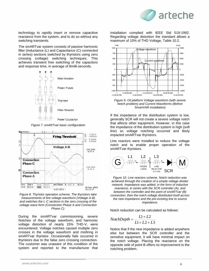
installation complied with IEEE Std 519-1992. Regarding voltage distortion the standard allows a maximum of 10% of THD Voltage, Table 10.2.
Figure 9. Oil platform Voltage waveform (with severe Notch problem) and Current Waveforms (Before
SmartVAR installation)
If the impedance of the distribution system is low, generally SCR will not create a severe voltage notch that affects other equipment. However, in this case the impedance of the distribution system is high (soft line) so voltage notching occurred and likely impacted smARTvar thyristors.
Line reactors were installed to reduce the voltage notch and to enable proper operation of the smARTvar thyristors.
Figure 10. Line reactors scheme. Notch reduction was achieved through the creation of a simple voltage divider network. Impedance was added, in the form of inductive
reactance, in series with the SCR controller (A), and between the controller and the point of smARTvar (B)
connection, then the notch voltage distributed itself across the new impedance and the pre-existing line to source
impedance.
Notch reduction can be calculated as follows:
Notice that if the new impedance is added anywhere else but between the SCR controller and the sensitive equipment, it will have minimal impact on the notch voltage. Placing the reactance on the opposite side of point B offers no improvement to the notching problem.
Main breaker
Powe r Fuses
Thyr istor
Filter Reactor
Power Ca pacitor
GSCR
MLINE
REACTOR
Z=7.5%
L1 L2 L3
FEDER
LINES
ABC
31
21NotchDepth
L L
L L2 L

www.arteche.com
5
Figure 11. Simplified inline diagram of the Oil Platform electrical system with Line Reactors and Dymanic VAR
Compensator.
Figure 12. Voltage and Current Waveforms (After Linea reactors and smARTvar installation)
Results reached with the smARTvar after Line Reactors installation:
Notch depth was reduced by 50%
Voltage Total Harmonic Distortion was reduced to < 5%
Current Total Harmonic Distortion was reduced to < 10%
True Power Factor was improved to 1.0 at all times
kVA demand was reduced from 3000 to 1800.
A better Power Quality environment for the rest of the equipment was created.
VII. CONCLUSION
The marine platform demand, current distortion and voltage distortion were reduced to acceptable levels and power factor is maintained at unity. This provided the customer with the capability to serve all loads from a single generator.
Besides the obvious energy savings and better performance of the equipment operating with only one generator. Many tons of CO2 (carbon dioxide) emissions to the environments will be avoided.
VIII. AUTHORS
Cesar Chavez is Manager of Engineering Dept. (Low Voltage products) at Arteche, a leading North American manufacturer of electrical power quality systems. Chavez earned his degree in Electrical Engineering from the Instituto Politecnico Nacional of Mexico. Chavez’s career has involved managerial responsibilities in MCC production, field engineering and design engineering. He has held positions responsible for the production, design, and commissioning of electrical power quality equipment. Chavez has extensive experience in the design, application and commissioning of reactive compensation and harmonic mitigation equipment. His expertise encompasses both passive and active solutions.
John Houdek (M’1985) received a bachelor’s degree in Electrical Engineering Technology from MSOE (Milwaukee School of Engineering), Milwaukee, Wisconsin, U.S.A. in 1981, and an MBA from Keller Graduate School of Management, Milwaukee, Wisconsin, U.S.A. in 1989.
His experience includes over twenty years of specialization in the design and application of electrical power quality equipment such as harmonic filters and PWM to sine wave conversion filters. As vice-president of marketing and sales for an electrical power quality equipment manufacturer, Houdek was responsible for global marketing and technical sales support. Houdek is a lecturer at MSOE and provides technical seminars and training on the subjects of electrical power quality and harmonics.
600Vca
3 Phase, 60 Hz
2190kW, 2738kVAG
600Vca, 3 Phase, 60 Hz
1800kW
Vdc
iVC M
G G
M 450kW
Vac
LINE REACTOR
SCR
Volts
-1000
22:35:59.80 5 22:35:59.81 0 22:35:59.81 5 22:35:59.82 0 22:35:59.82 5 22:35:59.83 0 22:35:59.835
-750
-500
-250
0
250
500
750
1000
Amps
-10000
-7500
-5000
-2500
0
2500
5000
7500
10000
Voltage wavef orm
Current waveform