e-pac (v02) e-series systems, c6, max user manual
TRANSCRIPT

E-PAC (V02)E-Series Systems, C6, MAXUser Manual

General Information
E-PAC (V02) User Manual
Version 4.0E, 09/1999, D2010.E.04
©by d&b audiotechnik AG 1997-1999; all rights reserved.
The information presented in this document is, to the best of ourknowledge, correct. We will however not be held responsible forthe consequences of any errors or omissions.
Technical specifications, weights and dimensions should always beconfirmed with d&b audiotechnik AG prior to inclusion in anyadditional documentation.
d&b audiotechnik AGEugen-Adolff-Strasse 134, D-71522 BacknangTelephone +49-7191-9669-0, Fax +49-7191-95 00 00
WARNING!
CAUTION!
IMPORTANT!
References in the manual
This refers to a potentiallydangerous situation which maylead to personal injury.
This refers to a potentiallydangerous situation which maylead to damage to theequipment.
This refers to a situation whichmay cause the equipment tomalfunction.
Symbols on the equipment
Please refer to the information in theoperating manual.
WARNING! Dangerous voltage!

WARNING!
CAUTION!
Safety precautions
Before you use our products, read the manualcarefully and observe all the safety precautions. Theywill protect you and help to avoid equipmentfailures. Keep this manual in a safe place so that it isavailable for future reference.
If you supply d&b products, please draw theattention of your customers to these safetyguidelines. Enclose the relevant manuals with thesystems. If you require additional manuals for thispurpose, you can order them from d&b (order formon the last page).
Information regarding use of the E-PAC
The device complies with the electromagnetic compatibilityrequirements of EN 55103 (product family standard for audio,video, audio-visual and entertainment lighting control apparatusfor professional use) for the environments E1 (residential), E2(business and commercial), E3 ( outdoor use in urban areas) andE4 (outdoor use in rural areas).
Acoustic interference and malfunctions may occur if the unit isoperated in the immediate vicinity of high-frequency transmitters(e.g. wireless microphones, mobile phones, etc.). Damage to themainframe is unlikely, but cannot be excluded.
To meet the EMC requirements, use only shielded cables withproperly connected plugs for all signal terminals (INPUT, INPUTLINK, MIX IN).
The following information is intended to prevent fires and possibleelectric shocks:
The E-PAC is a protective class 1 unit. Make sure that the earth(ground) contact is attached when the unit is in operation. Amissing earth (ground) contact may lead to dangerous voltages inthe housing and controls.
To reduce the possibility of audible hum the mainframe signalground (XLR pin 1) to earth (ground) connection has a highimpedance. It will prevent the unit from static charge but anyvoltage applied to signal ground will pass through all connectors.To prevent electric shock, make sure that all devices in the signalpath are grounded properly.
Never connect an amplifier output pin to any other in- or outputconnector pin or earth (ground). This might damage themainframe or lead to electric shock.
Lay all cables to and from the unit so that they cannot be crushedby vehicles or other equipment and that no-one can step on them.
Keep dust, moisture, water or other liquids well away from theunit.
Never operate the unit when it is open.

WARNING!
WARNING!
Always disconnect the mains power supply when replacing adefective fuse. Only use the type of fuse listed in the specifications.
Only carry out work specified in this manual and alwaysdisconnect the mains power supply.
All other work should be performed by trained service staff,especially in the following cases:
- Mains power cable or plug has been damaged
- Objects or liquids have entered the unit
- The unit is not operating normally
- The unit was dropped or the housing is damaged
Information regarding use of loudspeakers
Never stand in the immediate vicinity of loudspeakers driven at ahigh level. Professional loudspeaker systems are capable ofcausing a sound pressure level detrimental to human health.Seemingly non-critical sound levels (from approx. 95 dB SPL) cancause hearing damage if people are exposed to it over a longperiod.
In order to prevent accidents when deploying loudspeakers on theground or when flown, please take note of the following:
When setting up the loudspeakers or loudspeaker stands, makesure they are standing on a firm surface. If you place severalsystems on top of one another, use straps to secure them againstmovement.
Only use accessories which have been tested and approved byd&b for assembly and mobile deployment. Pay attention to thecorrect application and maximum loading capacity of theaccessories as specified in our Rigging Accessories Manual.
Ensure that all additional hardware, fixings and fasteners used forinstallation or mobile deployment are of an appropriate size andload safety factor. Pay attention to the manufacturers instructionsand to the relevant safety guidelines.
Regularly check the loudspeaker housings and accessories forvisible signs of wear and tear, and replace them when necessary.
Regularly check all load bearing bolts in the mounting devices.

CAUTION!Only use loudspeakers in the C and E-Series with the P1200Amainframe fitted with the correct controller modules or with acorrectly configured E-PAC. The contoller monitors cone excursionand voice coil temperature of the drivers. When loudspeakers areoperated without the correct controller, in addition to losses intone, there is a risk of damage to the components. Any defectsarising from operation other than those specified in this manualwill be excluded from any warranty claims.
Loudspeakers produce a static magnetic field even if they are notconnected or are not in use. Therefore make sure when erectingand transporting loudspeakers that they are nowhere nearequipment and objects which may be impaired or damaged by anexternal magnetic field. Generally speaking, a distance of 0.5 m(1.5 ft) from magnetic data carriers (floppy disks, audio and videotapes, bank cards, etc.) is sufficient; a distance of more than 1 m(3 ft) may be necessary with computer and video monitors.

E-PAC power amplifier controller front and rear views
E-PAC
ISP
ERR
O
+
6�6
�12
POWERON OFF MIX IN INPUTSPEAKER OUT
REMOTE INPUT LINK
REMOTELO IMP
DELAY ON
CUTHFA
SPKR
CAUTIONR ISK OF ELEC TR IC S HOC K
DO NOT OPEN
Made in Germany
® 21 3 4 5 6 87
220V-240V~ 50-60Hz T3.15ASPKR CONFIG.
E3
E9
LINEAR
C6
E12-SUB
E18-SUB
/
/
ON

Contents
1. Introduction......................................................... 1-11.1. System concept .......................................................................1-11.2. E-PAC based systems .............................................................1-21.3. Block diagram.........................................................................1-2
2. E-PAC power amplifier controller ....................... 2-12.1. Digital controller.....................................................................2-12.2. Power amplifier ......................................................................2-22.3. Cooling ....................................................................................2-22.4. Protection circuits ...................................................................2-22.5. Remote control and monitoring ...........................................2-32.6. Controls and indicators .........................................................2-42.7. Mains power switch ...............................................................2-62.8. Mains power connector and fuse .........................................2-62.9. Configuration switches...........................................................2-62.10. Connections ............................................................................2-82.11. Installation...............................................................................2-92.12. Dimensions ........................................................................... 2-102.13. Power consumption and power loss .................................. 2-112.14. REMOTE addressing............................................................ 2-122.15. Technical specifications....................................................... 2-13
3. Loudspeaker systems .......................................... 3-1E3E9C6 / C690MAXE12-SUBE18-SUB
4. System operation ................................................ 4-14.1. Setting up/stacking the loudspeakers ..................................4-14.2. Wiring......................................................................................4-24.3. Using the E-PAC MIX IN ........................................................4-34.4. Level setting of mid-high and SUB systems .........................4-4
5. Publications list ................................................... 5-1
6. EU declaration of conformity (CE symbol) ........... 6-1

(4.0E) 1-1
1. Introduction
This user manual describes the facilities and functions of d&bsystems which are operated with the E-PAC power amplifiercontroller. It covers the operation of the E-PAC and theloudspeakers used in these systems.
d&b publishes additional application and technical informationnotes (TI). Examples for different applications and combinations ofd&b C-Series and E-Series systems are given in TI 326.
A d&b publications list and order form is appended to this manualand we will gladly send you any of the listed publications onrequest. If you have any comments on the information presented,or feel that something is inadequately explained or not covered,then please tell us using the comments section of the publicationorder form.
1.1. System concept
All d&b loudspeaker systems are designed to meet the followingcriteria :
- Consistent neutral sound over the full working dynamic range
- Ease of operation
- Simple set up and wiring
- Safe and reliable operation
- Compact design
In order to satisfy these demands d&b developed a completesystem concept incorporating the loudspeaker, the loudspeakerspecific control electronics (the controller) and the power amplifier.
Fundamental to the performance of the loudspeaker is the caretaken in the development of individual components resulting inwell controlled dispersion, high efficiency and excellent dynamicresponse.
The controller creates the optimum mix of output level capability,operating reliability and longevity, and pure sound quality.Protective circuits continuously model the loudspeaker loadthrough simulation of cone displacement and voice coiltemperature ensuring signal level is only reduced when necessaryto prevent driver damage. No signal compression takes placewithin the systems normal operating range and there is nodynamic manipulation of system frequency response enabling mostapplications and acoustic environments to require no additionalsignal processing.
The power amplifier and control for each loudspeaker are housedwithin the A1 and P1200A mainframes or the E-PAC poweramplifier controller. All systems are compatible, easily combinedand complementary, and can be accessed using the d&b remotecontrol system to allow overview and control over the mostcomplex applications.

1-2 E-PAC (V02) User Manual
Output2+/2-
1+/1-
µController
ConfigLevel LED Display
DSPADCPower
Amplifier
ErrorDetection
InputAmplifier
Input
Link
Mix In
DAC
Remote
E-PAC power amplifier controller block diagram
1.2. E-PAC based systems
E-PAC, the E-Series Power Amplifier Controller, is a single channelamplifier with an internal controller for operating E-Series systems.Unlike the modular design of the controller modules for P1200Aand A1 mainframes, the internal controller is based on DigitalSignal Processing, DSP. The E-PAC is pre-programmed for E-Seriesand C6 loudspeakers and their different operational modes, theconfigurations are selected by setting DIP-switches on the rearpanel. The E-PAC has an additional linear configuration for MAXloudspeakers.
The E-PAC is specifically designed for high impedance loads (200W into 16 ohms, 300 W into 8 ohms), and therefore provides thesame output power for a single 16 ohm E3 loudspeaker as onechannel of a P1200A mainframe. The nominal 8 ohm impedance’sof other E-Series loudspeakers result in a single cabinet having amaximum SPL of 2 dB less than when driven by a P1200A.
Up to four E3 loudspeakers or two 8 ohms loudspeakers can bedriven with a reduced output level (–6 dB). This is useful forsituations where multiple loudspeakers are needed but maximumoutput is not required.
All the functions of the E-PAC, including programmable internaldelay settings, can be remotely interrogated and altered via theRIB, Remote Interface Bridge and a PC.
1.3. Block diagram

(4.0E) 2-1
IMPORTANT!
CAUTION!
2. E-PAC power amplifier controller
The E-PAC incorporates a power supply, single channel poweramplifier, Digital Signal Processor (DSP), all necessary protectioncircuits, a remote interface, controls and indicators.
The E-PAC is housed in a 2 RU high, rugged enclosure and can beoperated as a stand alone unit. Optional accessories allowinstallation of a single E-PAC in a standard 19“ equipment rack, ora pair mounted side by side.
2.1. Digital controller
The controller incorporated in the E-PAC is based on a DigitalSignal Processor, DSP, utilising sigma-delta signal conversion and ispre-programmed for E3, E9, C6, E12-SUB, E18-SUB and MAX(linear mode). These configurations can be selected by setting DIP-switches on the rear panel.
The signal processing includes correction of the frequencyresponse, a high pass filter, limiting and complex protection circuitsthat model loudspeaker cone displacement and voice coiltemperature.
The DIP switch settings are specific to the characteristics ofindividual loudspeakers, affecting the frequency response andmaximum output level. To ensure optimum performance andprevent damage to system components each type of loudspeakerhas to be used in conjunction with a suitably configured E-PAC.
Delay settings up to 170 ms can be programmed into thecontroller using a RIB, Remote Interface Bridge, in conjunction witha PC running d&b ROPE control software.
The E-PAC digital signal processing circuits introduce a processingdelay of 0.7 ms into the signal path, equivalent to a sound pathlength of 24 cm. If two identical loudspeakers are driven by digital(E-PAC) and analogue (P1200A) controllers respectively, the 0.7 msdelay of the E-PAC effectively positions its respective loudspeakerat a distance of 24 cm behind the loudspeaker driven by theP1200A. Where the two loudspeakers form an array this will leadto an increase in comb filtering and unpredictable coveragepatterns. If the distance between the cabinets is much greater thanthe path difference of 24 cm, this effect becomes negligible.
Please note that all digital signal processing equipment used in thesignal path will delay the signal. For example digital equalizershave a typical processing delay of about 3 ms.

2-2 E-PAC (V02) User Manual
IMPORTANT!
WARNING!
2.2. Power amplifier
The single channel power amplifier of the E-PAC maintains high linearitythroughout it’s operational range even into adverse loads. With fastresponse to, and recovery from overload conditions, stability andaccurate performance is guaranteed. A two stage power supply keepsthe losses through heat emission low.
The E-PAC can deliver 200 W continuous sine wave output power intoa 16 ohm load or 300 W into an 8 ohm load. Selecting low impedancemode (LO IMP DIP switch) enables the E-PAC to deliver an outputpower of 150 W into 4 ohms. These values apply to continuousoperation for a minimum of 30 minutes at a maximum ambienttemperature of 24°C (75°F).
An E-PAC will normally be operated with speech or music programme,complex signals where the average power requirement is below peakpower. The E-PAC will continue to operate indefinitely even where thesignal has very a low peak to RMS ratio (Crest factor, see section 2.13.),provided the device is installed to enable the heat generated to beadequately dissipated.
2.3. Cooling
The aluminium enclosure acts as a heat sink for the E-PAC power ampli-fier; it is therefore convection-cooled. To prolong the life of componentsinside the E-PAC, a small fan intakes cooling air into the front of the E-PAC through an opening on the rear panel. The fan is very quiet andruns continuously as long as the E-PAC is running or in mute.
When operating and installing the E-PAC, make sure enough air canflow around the enclosure. Never cover or block the intake opening onthe rear panel or the exit opening on the front panel. Also refer to Sec-tion 2.11., Installation.
Do not touch the heat sink. During operation the cooling fins of the heatsink on the enclosure of the E-PAC can reach temperatures of 80°C(176°F). The front and rear panels do not form part of the heat sinkand can be touched at any time.
2.4. Protective circuits
The E-PAC contains many integrated protective functions. If overtemperature occurs, the device switches to mute. After it hascooled down, the output stage cuts in automatically. The outputcurrent limiter (SOA watchdog) prevents damage to the outputstage that could occur from a short-circuit or incorrect cabling.
The mains power connection is protected by a fuse (see Section2.8.).
A mains inrush current limiter provides a „soft start“ and enablesseveral E-PACs to be powered up at the same time withoutoverloading the mains power supply. The maximum current drainduring the power up phase is 10 A (peak).

(4.0E) 2-3
2.5. Remote control & monitoring
The E-PAC is fitted with a remote interface for various levels of remotecontrol and system supervision. The remote interface connection isopto-coupled and floating.
Basic-RemoteThe Basic Remote is the simplest way to implement a remote controlsystem. E-PAC can be remotely powered on by simply applying an 18 -28 VDC control voltage to the terminals of its remote interfaceconnector. Connecting a simple detector circuit to the remote interfacealso allows remote warning of an E-PAC fault.
Details of basic circuits for remote power control and fault display arepublished in d&b technical information bulletin TI 212, available onrequest.
Control by the d&b Remote Interface Bridge (RIB)The d&b RIB is a 19“ rack mount device, 1 rack unit high. Up to 12mainframes (A1 or P1200A) or E-PACs at distances up to 500 m (1650ft) can each be directly connected via a twin wire to a RIB I/O port.From the front panel of the RIB each device can then be remotelypowered on and off and its power and error status monitored. A groupof E-PACs or mainframes can be switched directly by the RIB frontpanel MASTER ON/OFF switch or remotely via a connection to anopto-coupled input port on the rear panel of the RIB. Remote indicationof the error status of a mainframe group can also be relayed by theRIB.
Computer/MIDI controlUsing a PC and the d&b ROPE control software or a MIDI controldevice, up to eight RIBs can be controlled via RS232, RS422 or MIDIinterface. With an E-PAC the following remote control and displayoptions become available:
Remote control− Power On/Off
− Level control from +6 to –57.5 dB in 0.5 dB steps− MUTE switching
− Standby switching− Configuration switching (CUT, HFA, SPEAKER, LO IMP, DELAY ON)
− Delay time up to 170 ms in 0.1 ms steps
Remote status information− Configuration switch status (all rear panel DIP switches)
− Mute/Standby switch status− Level control setting
− Front panel indicator status (ISP, GR, ERR)− Protect status (internal protect, short circuit protect, thermal protect)
− Temperature status (ok/warning/off)− Available headroom (pre-limiter)
− Gain reduction (due to limiter operation)

2-4 E-PAC (V02) User Manual
IMPORTANT!
1
IMPORTANT!
E-PAC
ISP
ERR
O
+6–6
–12
E-PAC front panel controls
14
3
2
A detailed description of remote control with the d&b RIB is givenin the RIB user manual (d&b code D2903.E). The E-PAC objectaddresses for programming are to be found in section 2.14.
2.6. Controls and indicators
Mute/Standby switch (greenLED)
When the rear panel mains power switchis set to the on position, the combinedMute/Standby switch can be used toplace the E-PAC either in mute orstandby mode. The switch incorporates agreen LED indicator which indicates threedifferent states - ON, MUTE andSTANDBY.
− LED on: ON. The E-PAC is poweredon and ready for use. A brief press ofthe Mute/Standby switch will mutethe E-PAC, a longer press places theE-PAC in standby mode.
− LED regular flashing (1:1 mark space): MUTE. The E-PACis muted. In the mute state, the input signal is muted but thepower amp is still powered and connected to the speakeroutput. The E-PAC is unmuted by briefly pressing the Mute/Standby switch. A longer press of the Mute/Standby switch willplace the E-PAC in standby mode.
− Regular short flashes (1:8 mark space): STANDBY. Instandby mode the loudspeaker output is electronically isolatedand the E-PAC idles, drawing minimal mains power. Pressingthe Mute/Standby switch powers on the E-PAC ready for use.The E-PAC may also be powered back on by remote controlfrom standby mode.
When the E-PAC is set to STANDBY (or the mains power is turnedoff) the movement of the loudspeaker cones in the cabinetsconnected is no longer damped by the power amplifier output.This removal of the damping makes them susceptible to excitationby other loudspeakers in the surroundings. Audible resonancesmay occur, and even absorption of low frequency sound energyas the undamped loudspeakers act like a "bass trap". Topermanently mute single subwoofer cabinets it is thereforepreferable to use the MUTE function instead of STANDBY. TheSTANDBY mode, however, can be of advantage with mid-highsystems, because it will remove any residual noise from the system.
The Mute/Standby switch is a ‘soft’ switch which doesn’t electricallyisolate the E-PAC from the mains supply. The E-PAC circuitry canbe electrically isolated from the mains supply by switching the rearpanel mains power switch to its off position.
The setting of the Mute/Standby switch is stored in the E-PACwhen the mains power is turned off or disconnected. Afterreconnecting the E-PAC it will revert to the same status as beforedisconnection.

(4.0E) 2-5
2
3
4
Level controlThe detented level control adjusts the E-PAC input sensitivity andhas a 18 dB range, -12 dB to +6 dB, calibrated in 0.5 dB steps.The level control is normally set to 0 dB.
ISP LED- Input Signal Present (green)− Illuminates when the E-PAC input signal exceeds -36 dBu.
The ISP indication is unaffected by the setting of the levelcontrol and the MUTE function but will not operate inSTANDBY mode.
ERR LED - Error (red)The ERR LED is a combined display for gain reduction, overloadand error status of the E-PAC.
− Illuminates depending on the input signal (whilst thegreen ISP LED (3) also illuminates): Gain Reduction. The E-PAC limiter circuit reduces gain by more than 3 dB. This state isnot critical at all but shows the system has reached its limits.
− Illuminates depending on the input signal (whilst thegreen ISP LED (3) goes off): Overload. Either the input signallevel is too high or the E-PAC is trying to deliver too high anoutput current. If in doubt of the reason reduce the input gainat the E-PAC level control. If the error display disappears theoutput curent has been too high (load impedance too low fromtoo many speakers connected or a defective cable orconnector). If this does not affect the situation, the input signalto the E-PAC is too high (more than +18 dBu).
− Flashes periodically: Temperature overload. E-PAC isnow electronically muted with the speaker output disconnected.When the E-PAC has cooled to normal working temperature itwill automatically resume operation.
− Illuminates continuously whilst the Mute/Standby switchLED (1) flashes. An external fault has been detected such asa loudspeaker cable short or some other low impedance loadcondition. In this state the E-PAC is electronically muted and thespeaker output disconnected. Once the cause of the fault hasbeen identified and removed, the device has to be set tostandby mode to leave the error status. A further brief press ofthe Mute/Standby switch will reset the E-PAC ready to resumenormal operation.
− Illuminates continuously along with the Mute/Standbyswitch LED (1). An internal fault has been detected and theE-PAC electronically muted with the speaker outputdisconnected. As the E-PAC has no internal user serviceableparts, the unit will need the attention of an authorised d&bservice partner.

2-6 E-PAC (V02) User Manual
WARNING!
WARNING!
E-PAC rear panelconfiguration switches
REMOTELO IMP
DELAY ON
CUTHFA
SPKR21 3 4 5 6 87
ON
2.7. Mains power switch
The on/off switch is located on the rear panel and isolates themains power supply to the E-PAC. The switch on the front panelhas the functions ON/MUTE/STANDBY and does not isolate theE-PAC from the mains power supply.
2.8. Mains power connection and fuse protection
A 3-pin IEC socket with an integrated fuse holder is provided forconnecting the E-PAC to the mains power supply. A suitable powercable is supplied. Only connect the E-PAC to mains power supplieswith an earth (ground) conductor.
Make absolutely sure that earth (ground) is connected correctly.Before you connect the device, check that the mains voltage andfrequency corresponds to the specifications on the configurationsticker on the rear of the E-PAC.
A replaceable 20 mm fuse is integrated in the IEC mains socket(230 V version: 3.15 A Time Lag (T), 100 V and 115 V versions:5 A Time Lag (T)). It is connected in series to the primary windingof the mains transformer and fails if the current drain is exceeded.There is a spare fuse in the fuse holder.
If the fuse has failed disconnect the E-PAC from the mains supplybefore replacement. Only use a fuse of the correct type andnominal current value. Before restoring power to the E-PAC allcabling should be checked for faults. If in any doubt disconnect allsignal and loudspeaker connections.
2.9. Configuration switches
There are a total of 8 DIP switches on the rear panel of the E-PACfor configuring the controller and the output stage.
Switch 1 - CUTSet to CUT, a high pass filter is inserted in the controller signalpath. The speaker system is now configured for use with an activesubwoofer.
The cut-off frequency is 110 Hz for all configurations except thelinear mode (130 Hz). The CUT switch has no function insubwoofer configurations (E12-SUB, E18-SUB).
Switch 2 - HFAIn HFA mode (High Frequency Attenuation), the HF response of thespeaker system is rolled off. The HFA circuit configures theloudspeakers to provide a natural, balanced frequency responsewhen a unit is placed close to listeners in near field or delay use.
High Frequency Attenuation begins gradually at 1 kHz, droppingby approximately 3 dB at 10 kHz. This roll-off mimics the decline infrequency response experienced when listening to a system from adistance in a typically reverberant room or auditorium.
This switch has no function for subwoofer configurations (E12-SUB,E18-SUB).

(4.0E) 2-7
IMPORTANT!
IMPORTANT!
Switches 3 to 5 - SPKR (SPEAKER)Switches 3 to 5 configure the controller for specific loudspeakertypes. The switch positions are listed on the configuration sticker atthe rear of the device. Refer to the chapters on the individualloudspeaker systems for more details on the various modes.
Switch 6 - LO IMPIf LO IMP is selected, the speaker output of the E-PAC is set fordriving low-impedance loads. Gain and the maximum outputvoltage is then reduced by half (–6 dB) so that the E-PAC candrive loads at a nominal 4 to 8 ohms at lower power. For examplein LO IMP mode four E3 speakers can be operated.
Switch 7 - REMOTEAn E-PAC's power (on/off) and error status can be monitored byconnection to a Remote Interface Bridge, RIB. Detailed display ofthe local settings and status can be read when a RIB is used inconjunction with a PC running ROPE control software.
Selecting the E-PAC REMOTE switch enables a RIB to control the E-PAC configuration and power status. The RIB/ROPE combinationcan be used to disable the E-PAC from local control, and allowremote setting of DIP Switches 1-6, DIP Switch 8 and the associateddelay function, level control and the Mute/Standby switch.
If the link to a RIB is disconnected with the REMOTE switchselected, the E-PAC will switch off.
Switch 8 - DELAY ONThe E-PAC Version 2 has a programmable internal delay functionfor setting delay times up to 170 ms. The step widths are in units of0.1 ms and are set using the RIB in conjunction with a PC runningROPE control software. To programme the delay time switch 8,DELAY ON, is selected. This can be either manually or, when localoperation is disabled, via the ROPE control software.
Any delay programmed into an E-PAC will be retained in theinternal memory after the link to the RIB is disconnected. Thisenables a delay time for a particular application to be pre-programmed into the memory of an E-PAC and accessed bysimply selecting the DELAY ON switch. To override the delay,switch 8 is deselected.
In the standard operational mode with no internal delay selected,all versions of the E-PAC introduce a processing delay of 0.7 msinto the signal path.
If the E-PAC is operated without remote control and it has notbeen pre-programmed with a delay time for a specific application,the delay function should be disabled by deselecting DIP switch 8on the rear panel.

2-8 E-PAC (V02) User Manual
POWERON OFF MIX IN INPUTSPEAKER OUT
REMOTE INPUT LINK
REMOTELO IMP
DELAY ON
CUTHFA
SPKR
CAUTIONRISK O F ELECTRIC SHOCK
DO NOT OPEN
Made in Germany
® 21 3 4 5 6 87
220V-240V~ 50-60Hz T3.15ASPKR CONFIG.
E3
E9
LINEAR
C6
E12-SUB
E18-SUB
/
/
ON
E-PAC rear panel with connectors
Pin 1 (GND)
Pin 2 (pos. signal)
Pin 3 (neg. signal)
Pin assignments on E-PAC signal inputs
Pin assignment for remotecontrol
Pin 3 (+)
Pin 1 (–)
2.10. Connections
INPUT and INPUT LINKThe E-PAC signal input connector is a 3 pin female XLR. Below andwired in parallel is a 3 pin male XLR input link connector used tofeed the input signal on to the next device in the system signalchain.
MIX INA 3 pin female XLR connector provides a MIX IN input. A secondsignal fed to this input is summed to the main INPUT. If Left andRight components of a stereo source are fed to the main INPUTand MIX IN connections then a mono sum signal is derived fromthe speaker output. Please note that the resultant output is 3 dBhigher.
The output on the INPUT LINK connector is derived from the signalfed to the INPUT connector. An additional signal fed to the MIX INconnector will not appear at the INPUT LINK output.
SPEAKER OUTThe E-PAC is fitted with a single Speakon-NL4 speaker outputconnector. With configuration settings which transmit full-rangesignal (e.g. E3 or LINEAR) all four pins on the Speakon connectorare driven, pins 1+ and 2+ carry positive signal, 1– and 2– carrynegative signal. With SUB configurations selected pin 1+ isdisconnected automatically. This prevents mid-high cabinets fromaccidental damage by subwoofer signal.
REMOTEThe E-PAC is fitted with a two-wire serial remote control interface.The 3 pin female DIN remote control connector is located beneaththe speaker output. The connector is opto-coupled.
The remote functions are detailed in section 2.5. (Remote controland monitoring).

(4.0E) 2-9
Attachment of brackets and rack ears
1
2S
E-PACs with single/dual rack mount kit
12
34
5
Rack mount kit parts
IMPORTANT!
2.11. Installation
A single E-PAC, or a pair side by side, may be installed in astandard 19" equipment rack or flightcase. E-PACs require tworack units and, including connectors, a minimum rack depth of 40cm (15.7 "), mounting ridge to rack rear panel.
The single rack mount kit (Z2501) allows one E-PAC to be mountedeither to the left or the right hand side. It includes the followingparts:
− 1 front blanking panel (5)
− 1 front rack mounting bracket (2)− 1 rear mounted rack ear (3)
− 4 mounting rails (1)− Allen screws (S), Allen (Hex) srew
The dual rack mount kit (Z2502) includes the following parts:
− 2 front rack mounting brackets (2)− 2 rear mounted rack ears (3)
− 2 connector brackets (4)− 8 mounting rails (1)
− Allen screws (S), Allen (Hex) srewThe mounting rails are inserted into channels located in the sidewalls of the E-PAC aluminum enclosure. The different fittings areattached using countersunk Allen screws.
It is recommended that additional support be provided within therack by using the rear mounted rack ears. This is particularlyimportant if E-PACs are being racked for road use.

2-10 E-PAC (V02) User Manual
IMPORTANT!
ISP
ERR
O
+6–6
–12
E-PAC
190 [7.48"] 331 [13.03"]
E-PAC enclosure dimensions in mm [inch]
E-PAC enclosure dimensions with rack mount kit in mm [inch]
ISP
ERR
O
+6–6
–12
E-PAC
ISP
ERR
O
+6–6
–12
E-PAC
338 [13.31"]
483 [19.00"]465 [18.30"]
352 [13.86"]
The E-PAC enclosure can get hot during operation, therefore allowan air gap of at least 2 cm (3/4") between an E-PAC and the racktop/bottom panels, or other equipment above or below. This isnot necessary between adjacent E-PACs.
When installing E-PACs always allow sufficient free air flowaround the enclosure and never block or cover the rear panel airintake vent or the front panel air outlet vent. If E-PACs are to beinstalled in sealed equipment racks, then additional fan moduleswill be needed. The E-PAC air intake is at its rear panel; thereforeexternal fans should supply air to the inside of the rack.
2.12. Dimensions

(4.0E) 2-11
Signal waveform Crest factor
Square wave 1
Sine wave 1.4
Pink noise,compressed music
3.5
Music with mediumdynamic range
5
Speech, music withwide dynamic range
8
Examples of Crest factors
5 10 100 20030
100
400
consumption
loss
average output power [W]5 10 100 200
30
100
400
consumption
loss
average output power [W]
Average power consumption and loss of E-PAC as a factorof output power (W RMS into 16 ohms) with pink noisesignal
Power consumption and loss of E-PAC as a factor of outputpower (W RMS into 16 ohms) with sine wave signal
340
204
7843
--
484
318
131
67
--
239
150
5932
132
114
82
33
--
288
232
149
55
--
153
141
113
40
1.0 1.4 2.4 3.5 1.0 1.4 2.4 3.5 1.0 1.4 2.4 3.50
100
200
300
400
500
600
700
800
Crestfactor
4 ohms (LO IMP)8 ohms16 ohms
loss output
Maximum output power and power loss of E-PAC for different signalcharacteristics (Crest factors) at full level.
2.13. Power consumption and power loss
The power required from the mains supply and the waste heatproduced by the amplifiers power loss are variable figuresdepending on the load impedance and the signal levels andcharacteristics (e.g. speech, music).
In practice, the theoretical peak power consumption of a systemwill only be sustained for a short period of time. Basing mainscurrent and air conditioning plant requirements on the peakpower consumption of the sound system would result in agenerously over-specified installation. The key factor in powerconsumption calculations is the crest factor of the signal - the ratioof peak to sustainable RMS voltage of the signal.
Power input and electrical (⇒ thermal) power loss for differentsignal and load conditions can be derived from the graphs shownbelow.

2-12 E-PAC (V02) User Manual
E-PAC (V02) object addresses for remote operation with the d&b RIB
AddressRead/ Write Object Bit 6 Bit 5 Bit 4 Bit 3 Bit 2 Bit 1 Bit 0
0 RD Status Base Device Gnrl-Error SW-Rem LockCmd LockMode PWR Ok PWR On
0 WR Status Base Device LockCmd PWR On
1 RD/WR Switch Settings 2 DELAY ON
2 RD/WR Potentiometer Attenuation in steps of 0.5dB, 7-bit coded (0=+6dB, 127=–57.5dB)
3 RD/WR Switch Settings 1 MUTE Switch 5 LO IMP Switch 4 Switch 3 HFA CUT
6 RD/WR Delay time coarse Delay in steps of 10 ms, 7-bit coded (max. 17 = 170 ms)
7 RD/WR Delay time fine Delay in steps of 0.1 ms, 7-bit coded (max. 127 =12.7 ms)
8 RD Errors Base Device Tmp Error Tmp Warn AMP Protect AMP Error
10 RD Output Signal Present
12 RD LED's Controller ISP GR OVL
13 RD Headroom/GainRed 0..63:Headroom, 64..127:GainRed, 7-bit coded (0=32dB Hdrm, 64=0dB, 127=31.5dB GR)
2.14. REMOTE addressing
The basic structure of the E-PAC object addresses in the d&b RIB isidentical to the A1 (LO channel) or P1200A (channel A) addresses.
Compared with Version 1, the E-PAC Version 2 has an extendedfunctionality (programmable delay and additional systemconfigurations).
All Version 1 functions and object addresses are retainedunchanged on Version 2. Thus an E-PAC Version 2 can beoperated with a RIB/ROPE control, which was set up for E-PACVersion 1.

(4.0E) 2-13
2.15. Technical specifications
Nominal output power ................................................1 x 200 watts - 16 ohms(THD < 0.1%, sine wave).......................................................... 1 x 300 watts - 8 ohmsLO IMP setting ........................................................................... 1 x 150 watts - 4 ohmsFrequency response (–1 dB) ....................................................... 20 Hz ... 20 kHzDistortion (THD+N) ........................................................................................< 0.05 %from 1 W to rated output power, 20 Hz ... 20 kHzIntermodulation distortion (SMPTE) ................................................. < 0.05 %from 1 W to rated output powerResidual noise................................................................................................. > 98 dBbelow rated output power, 22 Hz ... 22 kHz, unweighted, RMS, 0 dB input gainSlew rate..............................................................................................................50V/uSDamping factor at loudspeaker output....................................................... > 1001 kHz, 16 ohms loadMax. output current .............................................................................±15A peakInput common mode rejection ........................................... > 50 dB at 50 HzMax. input level.............................................................................................+18 dBuSum of signals on INPUT and MIX INDigital signal processingSampling rate.........................................................................................................46.9 kHzResolution ..................................................................................................................... 24 bitProcessing delay........................................................................................................0.7 msMaximum delay setting...........................................................................................170 ms
Protection circuitsMains inrush current limiter....................................................................................< 10 AOver temperature heat sink/transformer............................................ 80°C / 130°COutput overload .................................................................................... SOA Watchdog
ConnectionsINPUT .....................................................................................................XLR 3-pin femalePin assignments ................... 1 = GND, 2 = pos. signal input, 3 = neg. signal inputInput impedance.................................................................................................. 44 kohmsINPUT LINK............................................................................................ XLR 3-pin maleparallel to inputMIX IN ...................................................................................................XLR 3-pin femaleInput impedance.................................................................................................. 44 kohmsSPEAKER OUT .........................................................................................Speakon-NL4Pin assignments for full range speakers...........................................1+ / 1–, 2+ / 2–Pin assignments for subwoofers..........................................................................2+ / 2–REMOTE.................................................................. DIN, 3-pin, 1 = –, 2 = n.c., 3 = +
GeneralHeight x width x depth ....................... 2 rack unit x 190 mm (7.5") x 331 mm (13")Weight...................................................................................................... 6.9 kg (15.2 lbs)Mains voltage (min/nominal/max) ....................... 195 /230 /265 V / 50 - 60 Hz........................................................... (115 V version: 98 / 115 / 132 V / 50 - 60 Hz)........................................................... (100 V version: 85 / 100 / 115 V / 50 - 60 Hz)Fuse ................................................................................................... 3.15 A Time Lag (T).............................................................. (100 V and 115 V versions: 5 A Time Lag (T))


(4.0E) 3-1
3. Loudspeaker systems
On the following pages you will find data sheets for the d&bsystems which can be operated with the E-PAC. The data sheetscontain information about the loudspeakers and operation withtheir respective E-PAC and P1200 controller settings.
E3
E9
C6 / C690
MAX
E12-SUB
E18-SUB

3-2 E-PAC (V02) User Manual

E3 Data Sheet E3
90
CAUTION!
E3 array, 120° coverage
E3
The E3 cabinet is a full range, two way bass-reflex enclosure.Fitted with a single 6.5" LF driver passively connected to a 1" HFcompression driver coupled to a constant directivity horn with a90° x 60° dispersion. Illustrated in the drawing on the left is an E3with the standard 90° horizontal horn configuration. The horn canbe rotated through 90° for a reversed 60° x 90° (h x v) dispersion.
The E3 cabinet is constructed from marine plywood with an impactresistant paint finish. The front of the loudspeaker cabinet is fittedwith a rigid metal grill covered with a replaceable acousticallytransparent foam. A connector plate with two parallel wiredSpeakon connectors, which can be swapped between the rear andside of the cabinet, together with pairs of M8 threaded inserts formounting brackets on each panel allow the E3 to be mounted inalmost any position.
The outstanding feature of the E3 is its neutral sound balancecoupled with an extraordinarily high output capability for acabinet of such a size. The E3 frequency response covers a 80 Hzto 17 kHz band making it extremely versatile and ideal for use innear field, delay, effects, ultra compact monitor and miniaturearray systems. Used with an auxiliary subwoofer system, the E3can also easily reproduce high level music programs. Suitablesubwoofers are E12-SUB, E18-SUB or C7-SUB.
With an asymmetrical cabinet design and an extensive range ofmounting and rigging accessories (please refer to the E-Seriesbrochure) E3 cabinets can be mounted or flown almost anywhereand used in pairs to create 120° or 180° horizontal arrays.
Only operate E3 loudspeakers with a d&b P1200A mainframefitted with E3 controller modules or a d&b E-PAC in E3configuration, otherwise there is a risk of damaging theloudspeaker components.
Altering the HF horn dispersion
The E3 HF horn has a square flange allowing it to rotate through90°. Two dispersion angles, 90° and 60°, are engraved on the flange,the value on the horizontal edge indicates the loudspeakers horizontaldispersion angle.
To change the horn dispersion, first remove the front grill byundoing the Allen screws (M4x25 mm) at the top and bottom ofthe grill using a 2.5 mm Allen key. Using a 3 mm Allen key, undothe 4 Allen screws (M4x25 mm) which hold the horn in place. Thehorn can then be rotated through 90°, refastened and the frontgrill replaced.
E3 (1.1E)
IMPORTANT!
Frequency response correction of HFA circuit
-5
0
5
10
-10
-15
-20
-25
-3020 100 1k 10k 20k
E3CUT
GRISP
MUTE
OVL
-12 dB
-6 +6
0
HFA
Controls on E3controller module
Connector wiring
PassiveCrossover
1+ 1– 2+ 2–
1+ 1– 2+ 2–
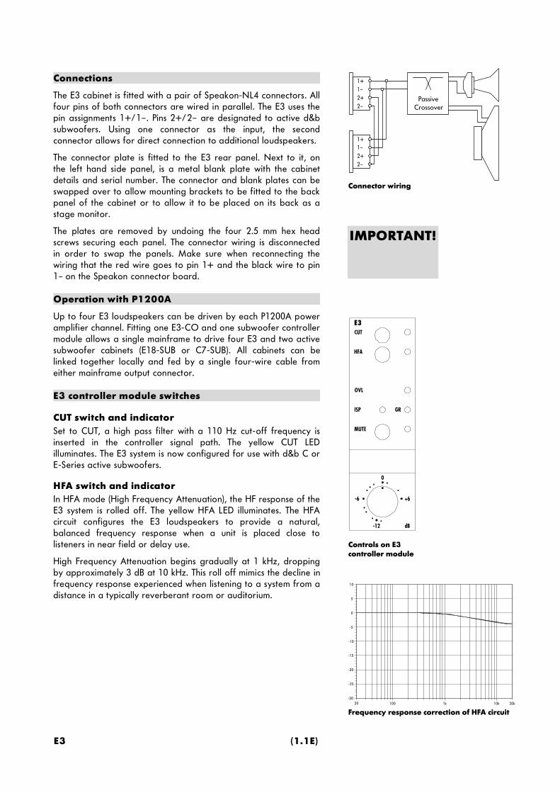
Connections
The E3 cabinet is fitted with a pair of Speakon-NL4 connectors. Allfour pins of both connectors are wired in parallel. The E3 uses thepin assignments 1+/1–. Pins 2+/2– are designated to active d&bsubwoofers. Using one connector as the input, the secondconnector allows for direct connection to additional loudspeakers.
The connector plate is fitted to the E3 rear panel. Next to it, onthe left hand side panel, is a metal blank plate with the cabinetdetails and serial number. The connector and blank plates can beswapped over to allow mounting brackets to be fitted to the backpanel of the cabinet or to allow it to be placed on its back as astage monitor.
The plates are removed by undoing the four 2.5 mm hex headscrews securing each panel. The connector wiring is disconnectedin order to swap the panels. Make sure when reconnecting thewiring that the red wire goes to pin 1+ and the black wire to pin1– on the Speakon connector board.
Operation with P1200A
Up to four E3 loudspeakers can be driven by each P1200A poweramplifier channel. Fitting one E3-CO and one subwoofer controllermodule allows a single mainframe to drive four E3 and two activesubwoofer cabinets (E18-SUB or C7-SUB). All cabinets can belinked together locally and fed by a single four-wire cable fromeither mainframe output connector.
E3 controller module switches
CUT switch and indicatorSet to CUT, a high pass filter with a 110 Hz cut-off frequency isinserted in the controller signal path. The yellow CUT LEDilluminates. The E3 system is now configured for use with d&b C orE-Series active subwoofers.
HFA switch and indicatorIn HFA mode (High Frequency Attenuation), the HF response of theE3 system is rolled off. The yellow HFA LED illuminates. The HFAcircuit configures the E3 loudspeakers to provide a natural,balanced frequency response when a unit is placed close tolisteners in near field or delay use.
High Frequency Attenuation begins gradually at 1 kHz, droppingby approximately 3 dB at 10 kHz. This roll off mimics the decline infrequency response experienced when listening to a system from adistance in a typically reverberant room or auditorium.

E3 Data Sheet E3
E3 isobar diagram, configuration 90° horizontal (standard)
E3 isobar diagram, configuration 90° vertical
E-PAC version 1 E-PAC version 2
E-PAC Configuration for E3
REMOTELO IMP
DELAY ON
CUTHFA
SPKR21 3 4 5 6 87
LO IMP1
REMOTE
21 3 4 5 6
2 3 4ONON
Operation with E-PAC
To drive E3 cabinets the E-PAC has to be configured to E3 modeby setting the appropriate DIP switches on the rear panel.
The E-PAC can drive up to two E3 cabinets at full output power.The rear panel LO IMP switch configures the E-PAC to drive amaximum of four E3 loudspeakers with a 6 dB reduction of input levelto the speakers.
DIP switches 1 and 2 respectively allow CUT and HFA settings to beselected. The individual characteristics of these functions are explainedon the previious page under the section "E3 controller moduleswitches“.
Dispersion characteristics
The diagrams below show dispersion angle vs frequency plottedusing lines of equal sound pressure (isobars) at -6 dB and -12 dB.

E3 (1.1E)
E3 cabinet dimensions in mm [inch] E3 wiring diagram
E3 frequency response, standard, CUT and HFA switch settings
-5
0
5
10
-10
-15
-20
-25
-3020 100 1k 10k 20k
Technical specifications
E3 system dataFrequency response (–5 dB) .................................................................80 Hz ... 18 kHzMax. sound pressure (1 m, free field)................................................................. 122 dB(SPLmax peak, pink noise test signal with crest factor of 4)Input level (SPLmax) ................................................................................................+9 dBuInput level (100 dB-SPL / 1 m)............................................................................ –10 dBuPolarity to controller INPUT (XLR pin 2: + / 3: –)................................. LF: + / HF: –
E3 loudspeakerNominal impedance .............................................................................................16 ohmsPower handling capacity (RMS / peak 10 ms) ......................................120 / 480 WNominal dispersion angle (hor. x vert.) .......................................................... 90° x 60°.............................................................................................(rotatable through 60° x 90°)Connections ........................................................................................... 2 x Speakon-NL4Pin assignments .......................................................................................................1+ / 1–Weight ...........................................................................................................7.2 kg (16 lbs)

E9 Data Sheet E9
CAUTION!
EP-5 1 2 3 4 5
NL4 1+ 1– 2+ 2– n.c.
Speakon- NL4 and EP-5 pin assignments
Connector wiring
PassiveCrossover
1+ 1– 2+ 2–
1+ 1– 2+ 2–
E9
The E9 cabinet is a full range, two way bass-reflex enclosure fittedwith a single 12" LF driver passively connected to a 2" HFcompression driver coupled to a vertically asymmetrical 90° x 50°CD horn. The asymmetry of the HF horn means that the E9 has avertical coverage pattern with a downward tilt. The actual verticaldispersion is 20° above and 30° below the cabinet axis.
The E9 cabinet is constructed from marine plywood and has animpact resistant paint finish. The front of the loudspeaker cabinetis fitted with a rigid metal grill covered with a replaceableacoustically transparent foam. The cabinet top plate has anintegral handle and four M10 threaded inserts for mountingbrackets and rigging. The L shaped metal plate at the bottom ofthe cabinet also incorporates a handle, four M10 threaded inserts,a socket to accept a loudspeaker stand and, on the rear panel, twoparallel wired Speakon-NL4 or EP-5 connectors.
The E9 frequency response is truly full range covering a 50 Hz to17 kHz band - even without an additional subwoofer, this is quitesufficient for many applications. The wide horizontal andasymmetric vertical dispersion makes the E9 especially suitable forclose coverage applications up to 15 m (50 ft) where it can bedeployed to best advantage mounted on a high stand.
The E9 can also be used as a stage monitor by simply placing thecabinet rear side down on stage (baffle angle 45°).
Within a larger system E9s are ideal as delays and for close, widecoverage work. The precisely angled rear side panels of thecabinet allow E9 cabinets to be simply placed side by side formingan array with accurate 90° horizontal coverage per loudspeaker.To simplify array construction an extensive range of mounting andrigging accessories are available - please refer to the E-Seriesbrochure.
The E9 system can be used with the d&b active subwoofer systemsE12-SUB, E18-SUB or C7-SUB. When operated with the P1200Amainframe the E9 may also be combined with the E15-BX passivebass extension.
Only operate E9 loudspeakers with a d&b P1200A mainframefitted with E9 controller modules or a d&b E-PAC (version 2) in E9configuration, otherwise there is a risk of damaging theloudspeaker components.
Connections
The E9 cabinet is fitted with a pair of Speakon-NL4 connectors. Allfour pins of both connectors are wired in parallel. The E9 uses thepin assignments 1+/1–. Pins 2+/2– are designated to C and E-Series active subwoofers. Using one connector as the input, thesecond connector allows for direct connection to additionalloudspeakers.
The E9 can be supplied with EP-5 output connectors as an option.Pin equivalents of Speakon-NL4 and EP-5 connectors are listed inthe table on the left.

E9 (1.1E)
E9CUT
GRISP
MUTE
OVL
-12 dB
-6 +6
0
BX
SUB
Controls on E9controller module
IMPORTANT!
E-PAC Configuration forE9 (E-PAC version 2)
REMOTELO IMP
DELAY ON
CUTHFA
SPKR21 3 4 5 6 87
ON
Operation with P1200A
Up to two E9 loudspeakers can be driven by each P1200A poweramplifier channel. Fitting one E9-CO and one subwoofer controllermodule allows a single mainframe to drive two E9 and two activesubwoofer cabinets (E18-SUB or C7-SUB). All cabinets can belinked together locally and fed by a single four-wire cable fromeither mainframe output connector.
The E9 can also be used with the E15-BX bass extension cabinet.The E15-BX cabinet is equipped with a passive crossover networkand simply connects in parallel with the E9 cabinet without theneed for any additional control electronics. One E9 and one E15-BX cabinet can be driven by each P1200A output channel.
E9 controller module switches
Standard settingIf the CUT switch and BX switch are not selected the module isconfigured for use with E9 loudspeakers when used as a standalone system without subwoofers.
CUT switch and indicatorSet to CUT, a high pass filter with a 110 Hz cut-off frequency isinserted in the controller signal path. The yellow CUT LEDilluminates. The E9 system is now configured for use with d&b C orE-Series active subwoofers.
BX switch and indicatorWhen the E9 is used with the passive E15-BX subwoofer, i.e. E9and E15-BX are linked to the same amplifier output, the BX switchshould be selected. The LF level - boosted by the bass extensioncabinet - is then attenuated by 3 dB, thereby increasing headroomat bass frequencies.
When E9 loudspeakers are deployed as stage monitors selecting the BXswitch reduces the low frequency energy gained from the couplingeffect of floor placement.
SUB (CUT and BX both selected)Selecting the CUT and BX switches activates a lowpass filter. Themodule now transmits frequencies from 50 to 110 Hz only,allowing the d&b E15-BX to be driven as an active subwoofer.
The E9-CO drives Speakon pins 1+/1– (EP-5: 1/2). Therefore theSUB setting is not suitable to drive d&b C/E-Series activesubwoofer cabinets.
Operation with E-PAC
To drive E9 cabinets the E-PAC has to be configured to E9 modeby setting the appropriate DIP switches on the rear panel (onlypossible with E-PAC version 2).
The E-PAC can drive a single E9 cabinet at an output power of300 watts. The rear panel LO IMP switch configures the E-PAC to drivetwo E9 cabinets with a 6 dB reduction of input level to the speakers.

E9 Data Sheet E9
Frequency response correction of HFA circuit(only available with E-PAC)
-5
0
5
10
-10
-15
-20
-25
-3020 100 1k 10k 20k
E9 isobar diagram
DIP switches 1 and 2 respectively allow CUT and HFA settings to beselected. The characteristics of the CUT setting are explained onthe previious page under the section "E9 controller moduleswitches".
The functions BX and SUB are not available with the E-PACcontroller.
HFA settingIn HFA mode (High Frequency Attenuation), the HF response of theE9 system is rolled off. The HFA circuit configures the E9loudspeakers to provide a natural, balanced frequency responsewhen a unit is placed close to listeners in near field or delay use.
High Frequency Attenuation begins gradually at 1 kHz, droppingby approximately 3 dB at 10 kHz. This roll-off mimics the decline infrequency response experienced when listening to a system from adistance in a typically reverberant room or auditorium.
Dispersion characteristics
The diagrams below show dispersion angle vs frequency plottedusing lines of equal sound pressure (isobars) at -6 dB and -12 dB.The nominal 90° horizontal dispersion is maintained from 20 kHzdown to 900 Hz.
E9 (1.1E)
E9 cabinet dimensions in mm [inch] E9 wiring diagram
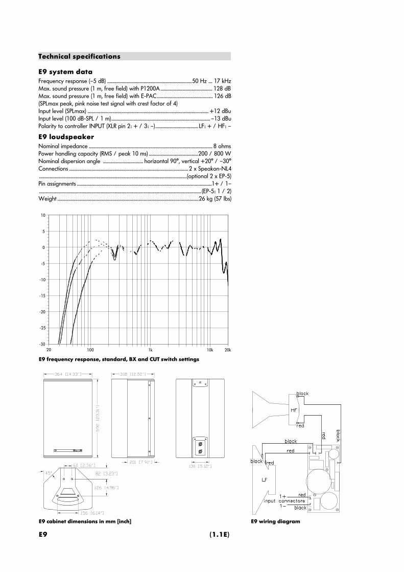
E9 frequency response, standard, BX and CUT switch settings
-5
0
5
10
-10
-15
-20
-25
-3020 100 1k 10k 20k
Technical specifications
E9 system dataFrequency response (–5 dB) .................................................................50 Hz ... 17 kHzMax. sound pressure (1 m, free field) with P1200A ........................................ 128 dBMax. sound pressure (1 m, free field) with E-PAC........................................... 126 dB(SPLmax peak, pink noise test signal with crest factor of 4)Input level (SPLmax) ............................................................................................. +12 dBuInput level (100 dB-SPL / 1 m)............................................................................ –13 dBuPolarity to controller INPUT (XLR pin 2: + / 3: –)................................. LF: + / HF: –
E9 loudspeakerNominal impedance ............................................................................................... 8 ohmsPower handling capacity (RMS / peak 10 ms) ......................................200 / 800 WNominal dispersion angle ............................... horizontal 90°, vertical +20° / –30°Connections ........................................................................................... 2 x Speakon-NL4.................................................................................................................(optional 2 x EP-5)Pin assignments .......................................................................................................1+ / 1–............................................................................................................................ (EP-5: 1 / 2)Weight ............................................................................................................26 kg (57 lbs)
C6/C690 Data Sheet C6
CAUTION!
EP-5 1 2 3 4 5
NL4 1+ 1– 2+ 2– n.c.
Speakon- NL4 and EP-5 pin assignments
Connector wiring
PassiveCrossover
1+ 1– 2+ 2–
1+ 1– 2+ 2–
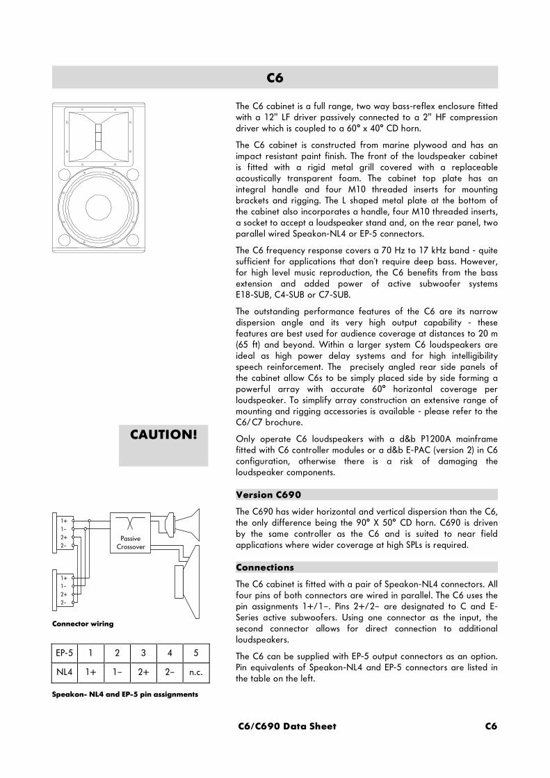
C6
The C6 cabinet is a full range, two way bass-reflex enclosure fittedwith a 12" LF driver passively connected to a 2" HF compressiondriver which is coupled to a 60° x 40° CD horn.
The C6 cabinet is constructed from marine plywood and has animpact resistant paint finish. The front of the loudspeaker cabinetis fitted with a rigid metal grill covered with a replaceableacoustically transparent foam. The cabinet top plate has anintegral handle and four M10 threaded inserts for mountingbrackets and rigging. The L shaped metal plate at the bottom ofthe cabinet also incorporates a handle, four M10 threaded inserts,a socket to accept a loudspeaker stand and, on the rear panel, twoparallel wired Speakon-NL4 or EP-5 connectors.
The C6 frequency response covers a 70 Hz to 17 kHz band - quitesufficient for applications that don’t require deep bass. However,for high level music reproduction, the C6 benefits from the bassextension and added power of active subwoofer systemsE18-SUB, C4-SUB or C7-SUB.
The outstanding performance features of the C6 are its narrowdispersion angle and its very high output capability - thesefeatures are best used for audience coverage at distances to 20 m(65 ft) and beyond. Within a larger system C6 loudspeakers areideal as high power delay systems and for high intelligibilityspeech reinforcement. The precisely angled rear side panels ofthe cabinet allow C6s to be simply placed side by side forming apowerful array with accurate 60° horizontal coverage perloudspeaker. To simplify array construction an extensive range ofmounting and rigging accessories is available - please refer to theC6/C7 brochure.
Only operate C6 loudspeakers with a d&b P1200A mainframefitted with C6 controller modules or a d&b E-PAC (version 2) in C6configuration, otherwise there is a risk of damaging theloudspeaker components.
Version C690
The C690 has wider horizontal and vertical dispersion than the C6,the only difference being the 90° X 50° CD horn. C690 is drivenby the same controller as the C6 and is suited to near fieldapplications where wider coverage at high SPLs is required.
Connections
The C6 cabinet is fitted with a pair of Speakon-NL4 connectors. Allfour pins of both connectors are wired in parallel. The C6 uses thepin assignments 1+/1–. Pins 2+/2– are designated to C and E-Series active subwoofers. Using one connector as the input, thesecond connector allows for direct connection to additionalloudspeakers.
The C6 can be supplied with EP-5 output connectors as an option.Pin equivalents of Speakon-NL4 and EP-5 connectors are listed inthe table on the left.

C6 (1.1E)
Controls on C6controller module
C6CUT
GRISP
MUTE
OVL
-12 dB
-6 +6
0
MON
160Hz
REMOTELO IMP
DELAY ON
CUTHFA
SPKR21 3 4 5 6 87
ON
E-PAC Configuration forC6 (E-PAC version 2)
Operation with P1200A
Up to two C6 loudspeakers can be driven by each P1200A poweramplifier channel. Fitting one C6-CO and one subwoofercontroller module allows a single mainframe to drive two C6 andtwo active subwoofer cabinets (E18-SUB, C4-SUB or C7-SUB). Allcabinets can be linked together locally and fed by a single four-wire cable from either mainframe output connector.
C6 controller module switches
Standard settingIf the CUT switch and MON switch are not selected the module isconfigured for use with C6 loudspeakers used as a stand alonesystem without subwoofers.
CUT switch and indicatorSet to CUT, a high pass filter with a 110 Hz cut-off frequency isinserted in the controller signal path. The yellow CUT LEDilluminates. The C6 system is now configured for use with d&b C-Series active subwoofers.
MON switch and indicator
If the MON switch is selected the yellow MON LED illuminates andthe low frequency level is reduced by 3 dB. This setting particularlyapplies to the C6-MON as this setting reduces the low frequencyenergy gained from the coupling effect of floor placement.
160Hz setting (CUT and MON switches both selected)If the 160Hz mode is selected, a high pass filter is inserted in thecontroller signal path. The crossover frequency of 160 Hz is higherthan in CUT mode and thus increases the available headroom inthe C6 system. The 160Hz mode can be selected when the systemis operated with d&b subwoofers C4-SUB, C7-SUB or E18-SUB(also in 160Hz mode, see manual section E18-SUB). Thisconfiguration is particularly useful when C6 loudspeakers arestacked directly on top of the subwoofer system.
Operation with E-PAC
To drive C6 cabinets the E-PAC has to be configured to C6 modeby setting the appropriate DIP switches on the rear panel (onlypossible with E-PAC version 2).
The E-PAC can drive a single C6 cabinet at an output power of300 watts. The rear panel LO IMP switch configures the E-PAC to drivetwo C6 cabinets with a 6 dB reduction of input level to the speakers.
DIP switches 1 and 2 respectively allow CUT and HFA settings to beselected. The characteristics of the CUT setting are explainedabove under the section "C6 controller module switches".
The functions MON and 160Hz are not available with the E-PACcontroller.

C6/C690 Data Sheet C6
Frequency response correction of HFA circuit(only available with E-PAC)
-5
0
5
10
-10
-15
-20
-25
-3020 100 1k 10k 20k
C6 Isobar diagram
HFA settingIn HFA mode (High Frequency Attenuation), the HF response of theC6 system is rolled off. The HFA circuit configures the C6loudspeakers to provide a natural, balanced frequency responsewhen a unit is placed close to listeners in near field or delay use.
High Frequency Attenuation begins gradually at 1 kHz, droppingby approximately 3 dB at 10 kHz. This roll-off mimics the decline infrequency response experienced when listening to a system from adistance in a typically reverberant room or auditorium.
Dispersion characteristics
The diagrams below show dispersion angle vs frequency plottedusing lines of equal sound pressure (isobars) at -6 dB and -12 dB.The nominal 60° horizontal dispersion is maintained from 20 kHzdown to 2 kHz.

C6 (1.1E)
C6 cabinet dimensions mm [inch] C6 wiring diagram
C6 frequency response, standard, CUT and 160Hz switch settings
-5
0
5
10
-10
-15
-20
-25
-3020 100 1k 10k 20k
Technical specifications
C6 (C690) system dataFrequency response (–5 dB) .................................................................70 Hz ... 17 kHzMax. sound pressure (1 m, free field) with P1200A ..............................133 (132) dBMax. sound pressure (1 m, free field) with E-PAC.................................131 (130) dB(SPLmax peak, pink noise test signal with crest factor of 4)Input level (SPLmax) ............................................................................................. +16 dBuInput level (100 dB-SPL / 1 m)..................................................................–14 (–13) dBuPolarity to controller INPUT (XLR pin 2: + / 3: –)................................. LF: + / HF: –
C6 (C690) loudspeakerNominal impedance ............................................................................................... 8 ohmsPower handling capacity (RMS / peak 10 ms) ......................................200 / 800 WNominal dispersion angle (hor. x vert.) ..................................... 60° x 40° (90° x 50°)Connections ........................................................................................... 2 x Speakon-NL4.................................................................................................................(optional 2 x EP-5)Pin assignments .......................................................................................................1+ / 1–............................................................................................................................ (EP-5: 1 / 2)Weight ............................................................................................................28 kg (62 lbs)

MAX Data Sheet MAX
MAX as a stage monitor(baffle angle 35°)
MAX as an array with 100° dispersion
MAX
MAX is a 2-way floor monitor system and uses a 15“/2“ coaxialdriver combination with a passive crossover. The driver designallows the use of a compact, low height cabinet. MAX can bedriven actively or passively.
Coaxially mounting the 2“ HF and 15“ LF drivers creates a verycompact single driver whilst retaining the benefits of separatemagnetic assemblies. The drivers are positioned together to utilisethe combined shape and geometry of the LF cone and HF horn tocreate a single waveguide with a controlled, symmetrical, 60°conical dispersion.
The MAX cabinet is constructed from marine plywood and has animpact resistant paint finish. The front of the loudspeaker cabinetis fitted with a rigid metal grill covered with a replaceableacoustically transparent foam. A socket to accept a loudspeakerstand, a ratchet strap kelping bar and optional MAN CF4 studplatesfor flying complete the possible rigging options for MAX. Fitted onthe rear panel are two parallel wired Speakon-NL4 or EP-5connectors.
The MAX cabinet does not require special controller electronics. Asa stage monitor MAX is preferably operated with the P1200Amainframe equipped with the ampMAX module. The ampMAXmodule can be configured for passive or 2-way active operation.
The negligible signal delay with this type of construction closelyapproximates the ideal acoustic point source. The result is aloudspeaker with remarkable vocal presence and clarity, aneutral, balanced sound, high feedback stability and a high soundpressure level capability. The frequency response covers a 85 Hzto 18 kHz band - sufficient for speech reinforcment and stagemonitor use.
MAX’s angled side panels allow a choice of two set up angleswhen placed on stage (35° or 67°). Together with a comprehensiverange of rigging hardware, the MAX cabinet allows fast and easydeployment, either as stage monitors or front of house in a mainPA system. Viewed from the top, the angle between the MAX sidepanels is 45°. MAX cabinets can be deployed side by side to createsemi-circular arrays, two cabinets result in an horizontal dispersion of100° and three cabinets 145°.
For applications which require deep bass, the LF response can beextended by using additional active subwoofer systems C7-SUB orC4-SUB. MAX can also be combined with the E15-BX passive bassextension speaker (not recommended when MAX is driven with anE-PAC).
MAX has been designed to match the dimensions of the C4 systemcabinets. Fitted with optional MAN stud plates, MAX can be flownbeneath a C4 system as downfills. To maintain the correct phaserelationship MAX cabinets are used in passive mode whencombined with C4 systems.

MAX (1.1E)
CAUTION!
Connector wiring (four wire operation)
MAX internal wiring of the connector panelto the crossover board in four wire and twowire operation
PassiveCrossover
1+ 1– 2+ 2–
1+ 1– 2+ 2–
PassiveCrossover
LF+ LF– HF+ HF– n.c.
EP-5 1 2 3 4 5
NL4 1+ 1– 2+ 2– n.c.
IMPORTANT!
Only operate MAX loudspeakers with a d&b P1200A mainframefitted with ampMAX or AMP-L controller modules or with an d&bE-PAC in linear configuration. As an alternative other high qualitypower amplifiers may be used, provided their output power doesnot exceed 500 watts into 8 ohms and an additional subsonic filteris used (25 Hz with 12 dB/octave minimum), otherwise there is arisk of damaging the loudspeaker components.
Connections
The MAX cabinet is fitted with a pair of Speakon-NL4 connectors.All four pins of both connectors are wired in parallel. Using oneconnector as the input, the second connector allows for directconnection to additional loudspeakers.
MAX can be supplied with EP-5 output connectors as an option.Pin equivalents of Speakon-NL4 and EP-5 connectors are listed inthe table on the right.
Four wire and two wire operation
To allow the choice of active or passive operation MAX cabinetsare driven by a four core cable. The HF and LF drivers are eachfed by their own pair of pins and separate passive crossovers. Pinsassignments 1+/1– connect the LF driver, pins 2+/2– connect theHF driver, as illustrated on the right.
For applications requiring dedicated passive use, the MAXcabinets internal wiring can be configured for connection to pins1+/1– allowing use of a two core cable.
The passive two wire configuration is also used when MAXcabinets are combined with C-Series active subwoofers. Driven bya P1200A mainframe fitted with one AMP-L and one C-Series SUBcontroller module the cabinets can be fed by a single four corecable and linked together locally.
To configure the cabinet for twin wire use the connector panel hasto be removed by undoing the four Allen screws with a 2.5 mmAllen key. The wiring on the back of the connector panel can bechanged to that shown in the lower illustration on the right.
In the twin wire/passive configuration both the LF and HF driversare connected to pins 1+/1–. Note that only the HF driver wiring(white and white/red) differs from that used in the four wireversion.
In the twin wire configuration MAX can also be used withamplifiers from other manufacturers. The amplifier or signaldistribution box needs to have positive signal on pin 1+ andnegative signal on pin 1– of it’s speakon output connectors.

MAX Data Sheet MAX
2 WAYACTIVE
MUTE
ampMAX
-12
-6 +6
0
-12
-6 +6
0
CUT
CH A / LOW
CH AACTIV E
LFC
CH B / HIGH
CH BHF-LEVEL
IS/GR
MUTE
CUT
LFC
IS/GR
Controls on ampMAX module
INPUT A
1+ 1– 2+ 2–
AMP A OUT A
INPUT B
1+ 1– 2+ 2–
AMP B OUT B
ActiveCrossover
Hi
Lo
P1200A with ampMAX, active mode
INPUT A
1+ 1– 2+ 2–
AMP A OUT A
INPUT B
1+ 1– 2+ 2–
AMP B OUT B
P1200A with ampMAX, passive mode
Operation with P1200A and ampMAX module
ampMAX is a two-channel controller module occupying both slotsof a P1200A mainframe. The combination of P1200A andampMAX allows MAX loudspeakers to be driven passively or in 2-way active mode.
Passive operationIn standard passive mode, ampMAX provides two linear amplifierchannels, each amplifier driving all four pins on the channelsSpeakon output connector. Pins 1+ and 2+ carry positive and pins1– and 2– carry the negative components of the signal. Two MAXcabinets can be driven by each P1200A amplifier channel.
MAX can also be used with the E15-BX bass extension cabinet. TheE15-BX cabinet is equipped with a passive crossover network andsimply connects in parallel with the MAX cabinet without the needfor any additional control electronics. One MAX and up to twoE15-BX cabinets can be driven by each P1200A output channel.
2-way active operationThe ampMAX module contains a switchable electronic crossoverwhich routes seperate LF and HF signals to the P1200A amplifierchannels. Pins 1+/1– of both loudspeaker outputs carry the LFsignal, 2+/2– carry HF signal. The output connector pin assignment ischanged automatically when active operation is selected. The inputsignal is fed to INPUT A, INPUT B is not used.
A P1200A mainframe can drive two MAX loudspeakers in active mode,the extra headroom gained serves for the most demanding monitorapplications.
When MAX systems are used as downfills or frontfills for C4Systems passive operation is recommended. In active mode thephase response of MAX is not compatible with C4 systems.
ampMAX module switches
2-WAY ACTIVE switch and indicatorSelecting this switch configures the P1200A for active operation ofMAX cabinets - channel A drives the 15" LF loudspeaker, whilstchannel B drives the 2" HF driver. The yellow LED next to the switchilluminates to indicate active mode.
The left volume control (CH A / ACTIVE) now controls both channelsand sets the overall level, the right volume control (CH B / HF-LEVEL)sets the relative HF level.
CUT switch and indicatorSet to CUT, a high pass filter with a 130 Hz cut-off frequency isinserted in the controller signal path. The yellow CUT LEDilluminates. MAX is now configured for use with d&b C-Seriesactive subwoofers. In active mode only the channel A CUT switchis functional.

MAX (1.1E)
AMP-LCUT
GRISP
MUTE
OVL
-12 dB
-6 +6
0
Controls on AMP-Lmodule
Frequency response of CUT and LFC circuits
-5
0
5
10
-10
-15
-20
-25
-3020 100 1k 10k 20k
LFC switch and indicatorWhen MAX cabinets are used without an active subwooferselecting LFC, Low Frequency Compensation, extends the lowfrequency response of MAX cabinets down to 65 Hz. The yellowLFC LED illuminates. In active mode only the channel A LFC switchis functional.
IS/GR indicatorsThese indicators give a three stage indication of ampMAX signallevels.
− Input Signal Present (green) illuminates when the signalpresented to the controller input exceeds a -36 dBu thresholdvalue. The ISP circuit is unaffected by the setting of thecontroller mute switch and level control.
− Gain Reduction (yellow) illuminates when the controllerlimiter reduces gain by more than 3 dB.
− Overload (red) illuminates when an overload occurs in thesignal path (input signal too high) or when the amplifier gain isreduced because the output current is too high (e.g. due to ashort circuit).
With active mode selected, the channel A indicators show the stateof the LF channel and the channel B indicators show the state ofthe HF channel.
Level controls in passive modeThe CH A and CH B detented level controls adjust the controllerinput sensitivity and have a 20 dB range, -14 dB to +6 dB, calibra-ted in 1 dB steps. The level controls are normally set to 0 dB.
Level controls in 2-way active modeIn active mode the CH A / ACTIVE level control adjusts thecontroller input sensitivity and has a 20 dB range, –14 db to +6dB, calibrated in 1 dB steps. The CH B/ HF-LEVEL control adjustsrelative HF level in 0.5 dB steps. For a flat response, whatever thesetting of the CH A / ACTIVE level control, the CH B / HF-LEVELcontrol should be set to 0 dB. The more precise 0.5 dB HF leveldetent settings invalidate the control scale markings. To accountfor the actual 10 dB range of HF level adjustment from –7 dB to+3 dB divide the control scale setting by two to arrive at theactual value for relative HF level.
Operation with P1200A and AMP-L module
The AMP-L module occupies a single P1200A module slot andprovides a single linear amplifier channel, which drives the pins1+/1– of the respective output connector. For operation with theAMP-L module MAX cabinets have to be configured for two wireoperation (see section "Four wire and two wire operation").
In passive mode up to two MAX loudspeakers can be driven byeach P1200A power amplifier channel. Fitting one AMP-L and onesubwoofer controller module allows a single mainframe to drivetwo MAX and two active subwoofer cabinets (C7-SUB or C4-SUB).All cabinets can be linked together locally and fed by a singlefour-core cable from either mainframe output connector.

MAX Data Sheet MAX
REMOTELO IMP
DELAY ON
CUTHFA
SPKR21 3 4 5 6 87
LO IMP1
REMOTE
21 3 4 5 6
2 3 4ONON
Frequency response correction of HFA circuit(only available with E-PAC version 2)
-5
0
5
10
-10
-15
-20
-25
-3020 100 1k 10k 20k
E-PAC version 1 E-PAC version 2
E-PAC Configuration for LINEAR mode
AMP-L module switches
CUT switch and indicatorSet to CUT, a high pass filter with a 130 Hz cut-off frequency isinserted in the controller signal path. The yellow CUT LEDilluminates. MAX is now configured for use with d&b C-Seriesactive subwoofers.
Operation with E-PAC
To drive MAX cabinets the E-PAC has to be configured to LINEARmode by setting the appropriate DIP switches on the rear panel.
In LINEAR mode all four pins on the Speakon connector are drivenby the E-PAC power amplifier, pins 1+ and 2+ carry positivesignal, 1– and 2– carry negative signal. MAX loudspeakers can beused in either four wire or two wire configuration.
The E-PAC can drive a single MAX cabinet at an output power of300 watts. The rear panel LO IMP switch configures the E-PAC to drivetwo MAX cabinets with a 6 dB reduction of input level to the speakers.
DIP switches 1 and 2 respectively allow CUT and HFA settings to beselected (only with E-PAC version 2). The characteristics of the CUTsetting are explained above under "AMP-L module switches".
HFA settingIn HFA mode (High Frequency Attenuation), the HF response of theMAX system is rolled off. The HFA circuit configures MAX toprovide a natural, balanced frequency response when a unit isplaced close to listeners in near field or delay use.
High Frequency Attenuation begins gradually at 1 kHz, droppingby approximately 3 dB at 10 kHz. This roll-off mimics the decline infrequency response experienced when listening to a system from adistance in a typically reverberant room or auditorium.

MAX (1.1E)
MAX frequency response, standard (linear), LFC and CUT switch settings
95
100
105
110
90
85
80
75
7020 100 1k 10k 20k
LFC
CUT
MAX isobar diagram
Dispersion characteristics
Due to the conical coverage pattern of the coaxial driver design,the horizontal and vertical dispersion characteristics of MAX arelargely identical (slight differences which do occur are attributableto the asymmetric cabinet shape). The diagram below showsdispersion angle versus frequency plotted using lines of equalsound pressure (isobars) at -6 dB and -12 dB. The nominal 60°dispersion angle is maintained from 4 to 10 kHz.
Frequency response
The graph below shows the different response curves for MAXdriven with the P1200A mainframe with ampMAX. The response instandard mode is equivalent to the operation with a linear poweramplifier (SPL at a distance of 1 m, output voltage 2.83 V).

MAX Data Sheet MAX
MAX cabinet dimensions in mm [inch]MAX wiring diagram
Technical specifications
MAX system data, passive setupMax. sound pressure (1 m, free field) with P1200A.........................................133 dBMax. sound pressure (1 m, free field) with E-PAC ...........................................131 dB(SPLmax peak, pink noise test signal with crest factor of 4)Input level (SPLmax) ..............................................................................................+13 dBuInput level (100 dB-SPL / 1 m) ............................................................................–17 dBuPolarity to controller INPUT (XLR pin 2: + / 3: –) ................................ LF: + / HF: –
MAX system data, active setup with ampMAXMax. sound pressure (1 m, free field) .................................................................135 dB(SPLmax peak, pink noise test signal with crest factor of 4)Input level (SPLmax) ..............................................................................................+15 dBuInput level (100 dB-SPL / 1 m) ............................................................................–17 dBuPolarity to controller INPUT (XLR pin 2: + / 3: –) ................................LF: + / HF: +
MAX loudspeakerFrequency response (–5 dB) ................................................................. 85 Hz ... 18 kHzSensivity (2.83 V / 1 m)...........................................................................................100 dBNominal impedance ................................................................................................8 ohmsPower handling capacity (RMS / peak 10 ms)....................................250 / 1200 WNominal dispersion angle ..............................................................................60° conicalConnections ............................................................................................2 x Speakon-NL4................................................................................................................. (optional 2 x EP-5)Pin assignments Speakon-NL4 ..................................................................... HF 2+ / 2–...............................................................................................................................LF 1+ / 1–Pin assignments EP-5 ............................................................................................HF 3 / 4.................................................................................................................................... LF 1 / 2Weight............................................................................................................26 kg (57 lbs)


E12-SUB Data Sheet E12-SUB
CAUTION!
Connector wiring
1+ 1– 2+ 2–
1+ 1– 2+ 2–
REMOTELO IMP
DELAY ON
CUTHFA
SPKR21 3 4 5 6 87
LO IMP1
REMOTE
21 3 4 5 6
2 3 4ONON
E-PAC version 1 E-PAC version 2
E-PAC Configuration for E12-SUB
CAUTION!
E12-SUB
The E12-SUB is a compact bass-reflex design employing a highexcursion 12" driver. The large, specially shaped reflex portenables the E12-SUB to achieve high sound pressure levels withminimal power compression and breathing effects.
The E12-SUB cabinet is constructed from marine plywood and hasan impact resistant paint finish. The front of the loudspeakercabinet is fitted with a rigid metal grill covered with a acousticallytransparent foam. The cabinet incorporates a steel handle in oneside and two parallel wired Speakon-NL4 connectors on the rearpanel.
Fitted to the top panel is an M20 threaded flange to accept theZ5013 Loudspeaker stand for the deployment of a single E3cabinet. To ensure sufficient stability the maximum permissibleweight of 10 kg (22 lbs) for the cabinet mounted on top of thestand must not be exceeded.
Designed to be actively driven using the E-PAC Power AmplifierController the E12-SUB covers the 50 Hz to 120 Hz frequencyband.
The compact E12-SUB has an extraordinarily high outputcapability for a cabinet of such a size - enough to support up totwo E3 cabinets. It is ideal for permanent or mobile use in smalland medium venues.
Only operate the E12-SUB with a d&b E-PAC in E12-SUBconfiguration (SUB configuration with E-PAC version 1), otherwisethere is a risk of damaging the loudspeaker components.
Connections
The E12-SUB cabinet is fitted with a pair of Speakon-NL4connectors. All four pins of both connectors are wired in parallel.The E12-SUB uses the pin assignments 2+/2–. Pins 1+/1– aredesignated to C and E-Series full range cabinets. Using oneconnector as the input, the second connector allows for directconnection to additional loudspeakers.
Operation with E-PAC
To drive E12-SUB cabinets the E-PAC has to be configured to E12mode by setting the appropriate DIP switches on the rear panel.The configuration E12-SUB on E-PAC version 2 is identical toconfiguration SUB on E-PAC version 1.
The E-PAC can drive a single E12-SUB at full output power.Connecting a second E12-SUB requires LO IMP mode to beselected on the E-PAC rear panel. Due to the 6 dB reduction of inputlevel to the speakers in low impedance mode there is no gain inacoustical output.
DIP switches 1 and 2 (CUT and HFA) are not functional with theconfiguration for E12-SUB.

E12-SUB (1.1E)
-5
0
5
10
-10
-15
-20
-25
-3020 100 1k 10k 20k
E12-SUB frequency response
E12-SUB cabinet dimensions in mm [inch]
Technical specifications
E12-SUB system dataFrequency response (–5 dB) .................................................................50 Hz ... 120 HzMax. sound pressure (1 m, free field)................................................................. 125 dB(SPLmax peak, pink noise test signal with crest factor of 4)Input level (SPLmax) ............................................................................................. +14 dBuInput level (100 dB-SPL / 1 m)...............................................................................–8 dBuPolarity to controller INPUT (XLR pin 2: + / 3: –)................................................ LF: +
E12-SUB loudspeakerNominal impedance ............................................................................................... 8 ohmsPower handling capacity (RMS / peak 10 ms) ......................................200 / 800 WConnections ........................................................................................... 2 x Speakon-NL4Pin assignments .......................................................................................................2+ / 2–Weight ............................................................................................................20 kg (44 lbs)

E18-SUB Data Sheet E18-SUB
CAUTION!
EP-5 1 2 3 4 5
NL4 1+ 1– 2+ 2– n.c.
Speakon- NL4 and EP-5 pin assignments
Connector wiring
1+ 1– 2+ 2–
1+ 1– 2+ 2–
E18-SUB
The E18-SUB is a compact, very low tuned bass-reflex designemploying a single 18" driver.
The E18-SUB loudspeaker cabinet is constructed from marineplywood and has an impact resistant paint finish. The front of theloudspeaker cabinet is fitted with a rigid metal grill covered with areplaceable acoustically transparent foam. Also at the front,fittings at the top and bottom edges of the cabinet are used tosecure an optional transport lid E7908. The cabinet incorporates apair of steel handles and, on the rear panel, four heavy dutywheels and two parallel wired Speakon-NL4 or EP-5 connectors.Fitted to the top panel is an M20 threaded flange to accept theZ5013 Loudspeaker stand for the deployment of a a full rangecabinet.
Designed to be actively driven using the d&b P1200A mainframeor the d&b E-PAC, the E18-SUB is normally used to support d&bfull range cabinets such as the E9, C6 or E3 by covering the 38 Hzto 110 Hz frequency band.
Only operate E18-SUB loudspeakers with a d&b P1200Amainframe fitted with E18 controller modules or a d&b E-PAC(version 2) in E18-SUB configuration, otherwise there is a risk ofdamaging the loudspeaker components.
Connections
The E18-SUB cabinet is fitted with a pair of Speakon-NL4connectors. All four pins of both connectors are wired in parallel.The E18-SUB uses the pin assignments 2+/2–. Pins 1+/1– aredesignated to C and E-Series full range systems. Using oneconnector as the input, the second connector allows for directconnection to additional loudspeakers.
The E18-SUB can be supplied with EP-5 output connectors as anoption. Pin equivalents of Speakon-NL4 and EP-5 connectors arelisted in the table below.

E18-SUB (1.1E)
E-PAC Configuration forE18-SUB (E-PAC version 2)
E18160Hz
GRISP
MUTE
OVL
-12 dB
-6 +6
0
Controls on E18controller module
REMOTELO IMP
DELAY ON
CUTHFA
SPKR21 3 4 5 6 87
ON
Operation with P1200A
Up to two E18-SUBs can be driven by each P1200A poweramplifier channel. Fitting one E18-SUB-CO and one C or E-SeriesTOP controller module allows a single mainframe to drive twoE18-SUB and two (E3: four) mid/high cabinets. All cabinets can belinked together locally and fed by a single four-wire cable fromeither mainframe output connector.
E18 Controller module switches
160Hz switch and indicatorIf the 160Hz switch is selected (yellow 160Hz LED illuminated), theupper operating frequency of the system is raised from 110 Hz to160 Hz. This setting can be used when E18-SUBs are used with theC6 system - the 160Hz setting on the C6-CO should also beselected to increase the C6 system's headroom (see C6 datasheet).
Operation with E-PAC
To drive E18-SUB cabinets the E-PAC has to be configured to E18mode by setting the appropriate DIP switches on the rear panel(only possible with E-PAC version 2).
The E-PAC can drive a single E18-SUB at an output power of 300watts. Connecting a second E18-SUB requires LO IMP mode to beselected on the E-PAC rear panel. Due to the 6 dB reduction of inputlevel to the speakers in low impedance mode there is no gain inacoustical output.
DIP switches 1 and 2 (CUT and HFA) are not functional with theconfiguration E18-SUB.
The 160Hz mode of the E18 controller module is not available onthe E-PAC controller.
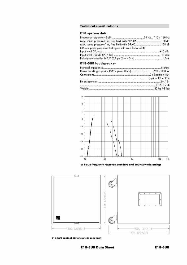
E18-SUB Data Sheet E18-SUB
E18-SUB frequency response, standard and 160Hz switch settings
-5
0
5
10
-10
-15
-20
-25
-3020 100 1k 10k 20k
E18-SUB cabinet dimensions in mm [inch]
Technical specifications
E18 system dataFrequency response (–5 dB) .....................................................38 Hz ... 110 / 160 HzMax. sound pressure (1 m, free field) with P1200A.........................................130 dBMax. sound pressure (1 m, free field) with E-PAC ...........................................128 dB(SPLmax peak, pink noise test signal with crest factor of 4)Input level (SPLmax) ..............................................................................................+15 dBuInput level (100 dB-SPL / 1m) ............................................................................–11 dBuPolarity to controller INPUT (XLR pin 2: + / 3: –) ............................................... LF: +
E18-SUB loudspeakerNominal impedance ................................................................................................8 ohmsPower handling capacity (RMS / peak 10 ms)......................................200 / 800 WConnections ............................................................................................2 x Speakon-NL4................................................................................................................. (optional 2 x EP-5)Pin assignments .......................................................................................................2+ / 2–............................................................................................................................ (EP-5: 3 / 4)Weight............................................................................................................42 kg (93 lbs)


(4.0E) 4-1
4. System operation
4.1. Setting up/stacking the loudspeakers
To get the best out of any high quality loudspeaker system it must beproperly set up. Care and attention needs to be paid to the position ofloudspeaker cabinets relative to each other and also to how they areangled and aimed towards the audience.
Vertical aimingThe aiming of the loudspeaker in the vertical plane is responsible forthe coverage all the way from the stage to the furthest listening point.Both the height and vertical angle of the loudspeakers need carefuladjustment. The best way to set the height and angle of cabinetsindependently to each other is to use a loudspeaker stand with thecabinet fitted to a swivel bracket. The loudspeaker stand can be theusual free standing type or a simple column stand fitted to the top of asubwoofer cabinet - both types are illustrated in the d&b systembrochures.
The lower the loudspeaker height, then the greater the sound leveldifference between the audience area at the front of the stage and thearea at the extreme range of the loudspeaker coverage. To give arelatively even level distribution the loudspeakers need to be placed ashigh as practicable.
In relatively confined spaces there is a risk of aiming too much energytowards the rear wall and ceiling, increasing the reverberantcomponent in the room. In the worst case bad speaker aiming cancreate an audible slap echo from the rear wall, slightly tilting theloudspeaker cabinets down towards the audience can reduce thisproblem.
Because it’s HF horn has a built-in 8° downward tilt, the E9 loudspeakeris ideally suited to this type of application. Usually there is no need touse a swivel bracket - the cabinet can be fixed straight on to aloudspeaker stand.
Horizontal aimingThe design of the C and E-Series cabinets simplifies horizontal aiming.The precisely angled rear side panels of the cabinets precisely definethe edges of a cabinet’s horizontal coverage. It is easy to gauge theextent of the horizontal coverage by sighting along a line from thesurface of each rear side panel of the cabinet.
Arraying mid/high cabinetsWith more than one loudspeaker source in a room, comb filter effectscan create coverage problems. Comb filtering creates an unevenfrequency response across an area which is reached by two or moresources at similar levels but at slightly different path lengths(interference between the signals).
Therefore arrays need to be constructed so that the coverage patternsof the individual loudspeakers combine with minimal overlap. Placingd&b C-Series cabinets with their rear angled side panels buttedtogether guarantees minimal dispersion pattern overlap and henceminimal interference.

4-2 E-PAC (V02) User Manual
Vertically stacking the cabinets, rather than horizontally arrayingthem is particularly useful in deep rooms where more than onecabinet has to be used because a single cabinet has insufficientthrow for the level needed at the back of the room. This helpsreduce interference in the horizontal plane and gives more verticaldirectivity.
4.2. Wiring
In order to keep losses in tone and power low the length of cablerun between mainframe and loudspeaker should be kept as shortas possible. A conductor size of 1.5 mm2 (16 AWG) is the minimumrequirement, 2.5 mm2 (12 AWG) is preferable.
When full range loudspeakers and actively driven subwoofers areoperated together, then - due to the different pin assignments ofthe systems - four-core cables have to be used.
We recommend the use of d&b MC4 cable (4 x 2.5 mm2 / 4 cond.12 AWG). MC4 cables retain their flexibility even at lowtemperatures and can be supplied in various lengths.
If very long cable runs are unavoidable in an installation, aconductor size greater than 2.5 mm2 (12 AWG) may be needed toreduce power loss and to achieve an acceptable damping factor(relation of load impedance to cable impedance). If the individualconductor size in a cable is insufficient, then it’s permissible to usetwo or more of the conductors.
The following ‘rule of thumb’ formula allows you to estimate themaximum cable length with an acceptable damping factor (>10):
maximum (single) length of cable [m] =3 x load impedance [ohms] x cross-section [mm2]
The parallel wired connectors fitted to all C-Series and E-Seriesloudspeakers allow the mainframe output signal to be fed directlyfrom one cabinet to another dispensing with the need for signaldistribution boxes.

(4.0E) 4-3
IMPORTANT!
MIX IN INPUTSPEAKER OUT
REMOTE INPUT LINK
REMOTELO IMP
DELAY ON
CUTHFA
SPKR21 3 4 5 6 87
ON
E-PAC
INPUT SIGNAL R
INPUT SIGNAL L
MIX IN INPUTSPEAKER OUT
REMOTE INPUT LINK
REMOTELO IMP
DELAY ON
CUTHFA
SPKR21 3 4 5 6 87
ON
E-PAC
MIX IN INPUTSPEAKER OUT
REMOTE INPUT LINK
REMOTELO IMP
DELAY ON
CUTHFA
SPKR21 3 4 5 6 87
ON
E-PAC
LINK LINK
E12-SUBE3 E3
Wiring of a stereo system with a mono subwoofer
4.3. Using the E-PAC MIX IN
The E-PAC is a single channel amplifier controller, the rear panelconnectors allow for use in different configurations. The illustrationbelow shows two E-PACs driving E3 loudspeakers from a stereosource, a third E-PAC drives an E12-SUB in mono. The left andright signals are summed to mono using the MIX input on the thirdE-PAC. Please note that the resultant output will be 3 db higher(see section 2.10.) .
The output on the INPUT LINK connector is derived from the signalto the INPUT connector. An additional signal fed to the MIX INconnector will not appear at the INPUT LINK output.

4-4 E-PAC (V02) User Manual
No. of systems Level gain
1 0 dB
2 3 dB
3 5 dB
4 6 dB
6 8 dB
10 10 dB
Average level gain when usingmultiple loudspeaker cabinets of thesame type.
4.4. Level setting of mid-high and SUB systems
With equal numbers of mid-high cabinets and correspondingactive subwoofers the input gains of TOP and SUB controller willnormally be set to the same level. This setting gives a correctsound balance and matches the characteristics of the activecrossover filters in the controller modules.
Using different ratios of mid-high to subwoofer systems will affectthe relative levels between the systems which will requirecorrection using the controller module level controls.
The level gain by using multiple cabinets of the same type can beevaluated with the table on the right or with the followingformula:
Level gain [dB] = 10 x log (number of systems)
Example: Using 10 subs together with 4 tops will give a level gainof 10 dB in the sub range and 6 dB in the top range. So the SUBcontrollers should be turned down by about 4 dB.
Relative to these nominal settings the balance between mid-highand subwoofers should not be changed more than approx. 3 dB,otherwise the crossover frequency between the systems is changedand overall sound quality may be deteriorated.
With E3 systems the correct balance is obtained using a ratio oftwo speakers to every subwoofer.
If the acoustic environment or the program material used requiresa severe correction in sound balance, it is much better to use anexternal equaliser in the signal path before both the full range andsubwoofer systems so that the level correction is applied equally toboth systems. This allows the frequency response of the wholesystem to be tuned without influencing the level, phase andfrequency response of the full range and subwoofer systemsrelative to each other.
The sensitivity values quoted for the systems are also a usefuladditional aid to relative level setting. The values in the technicalspecification for each loudspeaker give the input signal levelexpressed as the dBu value needed to produce a 100 dB (SPL)sound pressure level measured at one metre.
Example: the E9 system input sensitivity for a 100 dB-SPL is –13dBu, and that for the E3 system is –10 dBu. For equal sound levelfrom E3 and E9 loudspeakers used together, the E3 controller levelneeds to be set 3 dB higher than that of the E9 controller.

(4.0E) 5-1
5. Publications list
A number of publications with supplementary information on ourproducts are available. These publications are listed below alongwith their respective catalogue numbers. If you are interested inreceiving any of the listed publications then simply fill in the orderform on the last page of the User Manual, send it to d&b and wewill send you the requested information by return of post.
Title Cat. No.
TI 212 A1/P1200A Basic Remote D5212.E.
TI 326 C-Series/E-Series Configurations D5326.E.
Rigging Accessories Manual D2905.E.
d&b polar data disk for CADP2 D7501.000.
d&b polar data disk for EASE 2.x D7502.000.
Brochure F-Series D1102.E.
Brochure C4 System D1310.E.
Brochure C6/C7 Systems D1320.E.
Brochure E-Series D1201.E.
Brochure d&b Monitors D1401.E.
The Complete d&b D0011.E.
International Agents List D9220.D.
Complete Publications List D9300.E.


(4.0E) 6-1
6. EU declaration of conformity (CE symbol)
EU conformity of loudspeakers
This declaration applies to loudspeakers manufactured by d&baudiotechnik AG and includes the types listed in the table below:
− E1 Z0121
− E3 Z0300− E9 Z2250/Z2260
− E12-SUB Z0200− E18-SUB Z2253
− E15-BX Z1200− C6 / C690 Z2252/Z2262
− C6-MON Z2256− C7-TOP Z2257/Z2263
− C4-TOP Z2254− C4-SUB Z2255
− C7-SUB Z2259− MAX Z1100All production versions of these types are included, provided theycorrespond to the original technical version and have not beensubject to any later design or electromechanical modifications.
We herewith declare that said products are inconformity with the provisions of the following ECdirectives including all applicable amendments:
− 89/336 Electromagnetic Compatibility
The following standards have been applied:
− DIN EN 55013:08-1991
− DIN EN 55020:05-1995− DIN EN 50082-1:03-1993
d&b audiotechnik AG of Backnang acceptsresponsibility for this declaration.

d&b audiotechnik AG, Eugen-Adolff-Str.134, D-71522 Backnang, Germany, Phone. +49-7191-9669-0, Fax +49-7191-95 00 00
EU conformity of the E-PAC
This declaration applies to the E-PAC power amplifier controllermanufactured by d&b audiotechnik AG.
− E-PAC Z2500 all versionsAll production versions of type E-PAC starting from versionZ2500.000.01 are included, provided they correspond to theoriginal technical version and have not been subject to any laterdesign or electromechanical modifications.
We herewith declare that said products are inconformity with the provisions of the following ECdirectives including all applicable amendments:
− 73/23 Low Voltage
− 89/336 Electromagnetic Compatibility
The following standards have been applied:
− DIN EN 60065:1993
− DIN EN 55103-1:1996, classes E1 to E4− DIN EN 55103-2:1996, classes E1 to E4
d&b audiotechnik AG of Backnang acceptsresponsibility for this declaration.

E-PAC User Manual (4.0E)
Insert this page into an envelope or fax machine and send it to:
d&b audiotechnik AGEugen-Adolff-Straße 134D-71522 BacknangGermany
Fax +49-7191-95 00 00
My address:
Please send me the following information:Title Number
I think the manual is informative
I think the manual is well laid out
Suggestions for improvement or remarks on manual and products:
yes, very no

d&b audiotechnik AG, Eugen-Adolff-Str.134, D-71522 Backnang, Germany, Phone +49-7191-9669-0, Fax +49-7191-95 00 00


d&b audiotechnik AG, Eugen-Adolff-Str.134, D-71522 Backnang, Germany, Phone. +49-7191-9669-0, Fax +49-7191-95 00 00