easy-nlc ii user guide version 2 - thermo fisher scientific · 2017-09-12 · easy-nlc ii version...
TRANSCRIPT
EASY-nLC IIVersion 2.8
User Guide
60053-97000 Revision A September 2010

© 2010 Thermo Fisher Scientific Inc. All rights reserved.
EASY-nLC, EASY-Column, AFC, and IFC are trademarks, and Microtiter is a registered trademark of Thermo Fisher Scientific Inc.
PEEKsil is a trademark of SGE International Pty Ltd Corp.
This product uses FreeRTOS from www.freertos.org (available upon request). FreeRTOS is a trademark of Real Time Engineers Ltd.
The following are registered trademarks in the United States: Advion and RePlay are registered trademarks of Advion BioSystems, Inc. Duran is a registered trademark of Schott AG. PhotoMOS is a registered trademark of Panasonic Electric Works, Co., Ltd. VICI and Valco are registered trademarks of Valco Instruments Co., Inc.
Microsoft and Windows are registered trademarks of the Microsoft Corporation in the United States and other countries.
All other trademarks are the property of Thermo Fisher Scientific and its subsidiaries.
Thermo Fisher Scientific Inc. provides this document to its customers with a product purchase to use in the product operation. This document is copyright protected and any reproduction of the whole or any part of this document is strictly prohibited, except with the written authorization of Thermo Fisher Scientific Inc.
The contents of this document are subject to change without notice. All technical information in this document is for reference purposes only. System configurations and specifications in this document supersede all previous information received by the purchaser.
Thermo Fisher Scientific Inc. makes no representations that this document is complete, accurate or error-free and assumes no responsibility and will not be liable for any errors, omissions, damage or loss that might result from any use of this document, even if the information in the document is followed properly.
This document is not part of any sales contract between Thermo Fisher Scientific Inc. and a purchaser. This document shall in no way govern or modify any Terms and Conditions of Sale, which Terms and Conditions of Sale shall govern all conflicting information between the two documents.
Release history: Revision A, September 2010
Software version: EASY-nLC II version 2.8
For Research Use Only. Not for use in diagnostic procedures.
Thermo Scientific EASY-nLC II User Guide iii
C
Preface . . . . . . . . . . . . . . . . . . . . . . . . . . . . . . . . . . . . . . . . . . . . . . . . . . . . . . . . . . . . . viiRelated Documentation . . . . . . . . . . . . . . . . . . . . . . . . . . . . . . . . . . . . . . . . . .viiiSafety and Special Notices . . . . . . . . . . . . . . . . . . . . . . . . . . . . . . . . . . . . . . . .viii
Safety Practices . . . . . . . . . . . . . . . . . . . . . . . . . . . . . . . . . . . . . . . . . . . . . . .viiiSpecial Notices . . . . . . . . . . . . . . . . . . . . . . . . . . . . . . . . . . . . . . . . . . . . . . .viii
Contacting Us . . . . . . . . . . . . . . . . . . . . . . . . . . . . . . . . . . . . . . . . . . . . . . . . . .ixDeclaration of Conformity . . . . . . . . . . . . . . . . . . . . . . . . . . . . . . . . . . . . . . . .xiv
U.S. Safety and EMC (Electromagnetic Compliance) Standards . . . . . . . . . .xivCanadian Safety and EMC (Electromagnetic Compliance) Standards . . . . . . xvEuropean Safety and EMC (Electromagnetic Compliance) Standards . . . . . . xv
Chapter 1 Introduction . . . . . . . . . . . . . . . . . . . . . . . . . . . . . . . . . . . . . . . . . . . . . . . . . . . . . . . . . . .1Product Description . . . . . . . . . . . . . . . . . . . . . . . . . . . . . . . . . . . . . . . . . . . . . . 2
System Components . . . . . . . . . . . . . . . . . . . . . . . . . . . . . . . . . . . . . . . . . . . . 2System Configuration for Two-Column Setup . . . . . . . . . . . . . . . . . . . . . . . . 3System Configuration for a One-Column Setup . . . . . . . . . . . . . . . . . . . . . . . 4Instrument Operation . . . . . . . . . . . . . . . . . . . . . . . . . . . . . . . . . . . . . . . . . . . 4Pump Flow Control . . . . . . . . . . . . . . . . . . . . . . . . . . . . . . . . . . . . . . . . . . . . 5
Graphical Hardware Overview . . . . . . . . . . . . . . . . . . . . . . . . . . . . . . . . . . . . . . 7
Chapter 2 Installation . . . . . . . . . . . . . . . . . . . . . . . . . . . . . . . . . . . . . . . . . . . . . . . . . . . . . . . . . . .11Placement . . . . . . . . . . . . . . . . . . . . . . . . . . . . . . . . . . . . . . . . . . . . . . . . . . . . . 11Power . . . . . . . . . . . . . . . . . . . . . . . . . . . . . . . . . . . . . . . . . . . . . . . . . . . . . . . . 11Temperature and Humidity . . . . . . . . . . . . . . . . . . . . . . . . . . . . . . . . . . . . . . . 12Lifting Instruction . . . . . . . . . . . . . . . . . . . . . . . . . . . . . . . . . . . . . . . . . . . . . . . 12External Connections . . . . . . . . . . . . . . . . . . . . . . . . . . . . . . . . . . . . . . . . . . . . 12
Connecting to the Mass Spectrometer through Contact Closure . . . . . . . . . . 13Connecting to Remote Support. . . . . . . . . . . . . . . . . . . . . . . . . . . . . . . . . . . 13Connecting to a Local Area Network for Data Exchange. . . . . . . . . . . . . . . . 14Attaching Mouse and Keyboard to the USB Connections . . . . . . . . . . . . . . . 14Attaching Add-on Products through the P-Bus and RS-232 . . . . . . . . . . . . . 14
Flow Parts and Lines . . . . . . . . . . . . . . . . . . . . . . . . . . . . . . . . . . . . . . . . . . . . . 15
Chapter 3 Instrument Control Software. . . . . . . . . . . . . . . . . . . . . . . . . . . . . . . . . . . . . . . . . . . .17Using the Touch-Sensitive Screen . . . . . . . . . . . . . . . . . . . . . . . . . . . . . . . . . . . 18Starting the EASY-nLC II System . . . . . . . . . . . . . . . . . . . . . . . . . . . . . . . . . . . 19
Contents
Contents
iv EASY-nLC II User Guide Thermo Scientific
User Interface Layout . . . . . . . . . . . . . . . . . . . . . . . . . . . . . . . . . . . . . . . . . . . . 20General Interaction Principles . . . . . . . . . . . . . . . . . . . . . . . . . . . . . . . . . . . . . . 21Application Menu Structure . . . . . . . . . . . . . . . . . . . . . . . . . . . . . . . . . . . . . . . 21
Home . . . . . . . . . . . . . . . . . . . . . . . . . . . . . . . . . . . . . . . . . . . . . . . . . . . . . . 22Batch Setup . . . . . . . . . . . . . . . . . . . . . . . . . . . . . . . . . . . . . . . . . . . . . . . . . . 23Method Editor . . . . . . . . . . . . . . . . . . . . . . . . . . . . . . . . . . . . . . . . . . . . . . . 25Maintenance . . . . . . . . . . . . . . . . . . . . . . . . . . . . . . . . . . . . . . . . . . . . . . . . . 27Configuration . . . . . . . . . . . . . . . . . . . . . . . . . . . . . . . . . . . . . . . . . . . . . . . . 29
Logging In to the EASY-nLC II System. . . . . . . . . . . . . . . . . . . . . . . . . . . . . . . 32Closing Down the EASY-nLC II System . . . . . . . . . . . . . . . . . . . . . . . . . . . . . . 33
Chapter 4 Configuring the EASY-nLC II System . . . . . . . . . . . . . . . . . . . . . . . . . . . . . . . . . . . . .35Setting Up the Mass Spectrometer Connection . . . . . . . . . . . . . . . . . . . . . . . . . 35Network Connection. . . . . . . . . . . . . . . . . . . . . . . . . . . . . . . . . . . . . . . . . . . . . 36User Permissions . . . . . . . . . . . . . . . . . . . . . . . . . . . . . . . . . . . . . . . . . . . . . . . . 38
Changing the Administrator Password. . . . . . . . . . . . . . . . . . . . . . . . . . . . . . 39Creating New User Accounts. . . . . . . . . . . . . . . . . . . . . . . . . . . . . . . . . . . . . 40Configuring Column Setup, Loop Volume, Idle Flow, and IFC . . . . . . . . . . 40
Chapter 5 Preparation for Use. . . . . . . . . . . . . . . . . . . . . . . . . . . . . . . . . . . . . . . . . . . . . . . . . . . .43Preparing Solvent Bottles and Waste Containers . . . . . . . . . . . . . . . . . . . . . . . . 43
Solvent A and B Bottles . . . . . . . . . . . . . . . . . . . . . . . . . . . . . . . . . . . . . . . . . 44Autosampler Bottles . . . . . . . . . . . . . . . . . . . . . . . . . . . . . . . . . . . . . . . . . . . 44Waste Container . . . . . . . . . . . . . . . . . . . . . . . . . . . . . . . . . . . . . . . . . . . . . . 45
Executing Maintenance Scripts . . . . . . . . . . . . . . . . . . . . . . . . . . . . . . . . . . . . . 46Purging and Flushing the Pumps. . . . . . . . . . . . . . . . . . . . . . . . . . . . . . . . . . . . 47Installing Columns . . . . . . . . . . . . . . . . . . . . . . . . . . . . . . . . . . . . . . . . . . . . . . 50
Preparing the Pre-Column. . . . . . . . . . . . . . . . . . . . . . . . . . . . . . . . . . . . . . . 51Equilibrating the Analytical Column . . . . . . . . . . . . . . . . . . . . . . . . . . . . . . . 52
Chapter 6 Running the First Sample. . . . . . . . . . . . . . . . . . . . . . . . . . . . . . . . . . . . . . . . . . . . . . .53Preparing a Well Plate . . . . . . . . . . . . . . . . . . . . . . . . . . . . . . . . . . . . . . . . . . . . 54Creating a Method . . . . . . . . . . . . . . . . . . . . . . . . . . . . . . . . . . . . . . . . . . . . . . 54
Page 1/5 . . . . . . . . . . . . . . . . . . . . . . . . . . . . . . . . . . . . . . . . . . . . . . . . . . . . 54Page 2/5 . . . . . . . . . . . . . . . . . . . . . . . . . . . . . . . . . . . . . . . . . . . . . . . . . . . . 55Page 3/5 . . . . . . . . . . . . . . . . . . . . . . . . . . . . . . . . . . . . . . . . . . . . . . . . . . . . 56Page 4/5 . . . . . . . . . . . . . . . . . . . . . . . . . . . . . . . . . . . . . . . . . . . . . . . . . . . . 58Page 5/5 . . . . . . . . . . . . . . . . . . . . . . . . . . . . . . . . . . . . . . . . . . . . . . . . . . . . 59
Creating a Batch . . . . . . . . . . . . . . . . . . . . . . . . . . . . . . . . . . . . . . . . . . . . . . . . 60Starting Sample Acquisition . . . . . . . . . . . . . . . . . . . . . . . . . . . . . . . . . . . . . . . 63Monitoring the Run . . . . . . . . . . . . . . . . . . . . . . . . . . . . . . . . . . . . . . . . . . . . . 63
Using the Overview Page in the Home Menu . . . . . . . . . . . . . . . . . . . . . . . . 64Using the Graphs Page in the Home Menu . . . . . . . . . . . . . . . . . . . . . . . . . . 65
Contents
Thermo Scientific EASY-nLC II User Guide v
Stopping Sample Acquisition. . . . . . . . . . . . . . . . . . . . . . . . . . . . . . . . . . . . . . . 66Editing the Running Batch . . . . . . . . . . . . . . . . . . . . . . . . . . . . . . . . . . . . . . . . 67Troubleshooting a Sample Run . . . . . . . . . . . . . . . . . . . . . . . . . . . . . . . . . . . . . 70
Chapter 7 Autosampler Calibration . . . . . . . . . . . . . . . . . . . . . . . . . . . . . . . . . . . . . . . . . . . . . . .71Replacing the Autosampler Adapter Plate . . . . . . . . . . . . . . . . . . . . . . . . . . . . . 72Managing Plate Formats . . . . . . . . . . . . . . . . . . . . . . . . . . . . . . . . . . . . . . . . . . 75Preparation and Basic Principles . . . . . . . . . . . . . . . . . . . . . . . . . . . . . . . . . . . . 77Calibrating Plates . . . . . . . . . . . . . . . . . . . . . . . . . . . . . . . . . . . . . . . . . . . . . . . 78Calibrating the Wash/Waste Compartment. . . . . . . . . . . . . . . . . . . . . . . . . . . . 81
Chapter 8 Troubleshooting. . . . . . . . . . . . . . . . . . . . . . . . . . . . . . . . . . . . . . . . . . . . . . . . . . . . . . .87Running a Batch . . . . . . . . . . . . . . . . . . . . . . . . . . . . . . . . . . . . . . . . . . . . . . . . 88Autosampler . . . . . . . . . . . . . . . . . . . . . . . . . . . . . . . . . . . . . . . . . . . . . . . . . . . 90Contact Closure . . . . . . . . . . . . . . . . . . . . . . . . . . . . . . . . . . . . . . . . . . . . . . . . 92Network Access . . . . . . . . . . . . . . . . . . . . . . . . . . . . . . . . . . . . . . . . . . . . . . . . . 92Starting Up the System . . . . . . . . . . . . . . . . . . . . . . . . . . . . . . . . . . . . . . . . . . . 93System Component States (Valves, Pumps, Autosampler, and Plate
Cooler) . . . . . . . . . . . . . . . . . . . . . . . . . . . . . . . . . . . . . . . . . . . . . . . . . . . . . 93Miscellaneous . . . . . . . . . . . . . . . . . . . . . . . . . . . . . . . . . . . . . . . . . . . . . . . . . . 94
Chapter 9 Remote Support . . . . . . . . . . . . . . . . . . . . . . . . . . . . . . . . . . . . . . . . . . . . . . . . . . . . . . .97Connecting the EASY-nLC II System to the Support Server . . . . . . . . . . . . . . . 97Saving System Files on a USB Removable Storage Device . . . . . . . . . . . . . . . . . 99
Chapter 10 Maintenance . . . . . . . . . . . . . . . . . . . . . . . . . . . . . . . . . . . . . . . . . . . . . . . . . . . . . . . .103Daily Maintenance . . . . . . . . . . . . . . . . . . . . . . . . . . . . . . . . . . . . . . . . . . . . . 103Quarterly Maintenance . . . . . . . . . . . . . . . . . . . . . . . . . . . . . . . . . . . . . . . . . . 104Yearly Maintenance . . . . . . . . . . . . . . . . . . . . . . . . . . . . . . . . . . . . . . . . . . . . . 104Maintenance Scripts . . . . . . . . . . . . . . . . . . . . . . . . . . . . . . . . . . . . . . . . . . . . 105
Prepare – Purge Solvent. . . . . . . . . . . . . . . . . . . . . . . . . . . . . . . . . . . . . . . . 106Prepare – Flush Air . . . . . . . . . . . . . . . . . . . . . . . . . . . . . . . . . . . . . . . . . . . 107Prepare – Precolumn Equilibration . . . . . . . . . . . . . . . . . . . . . . . . . . . . . . . 108Prepare – Analytical Col Equilibration . . . . . . . . . . . . . . . . . . . . . . . . . . . . 109Prepare – Isocratic Flow . . . . . . . . . . . . . . . . . . . . . . . . . . . . . . . . . . . . . . . 110Test – MS Connection . . . . . . . . . . . . . . . . . . . . . . . . . . . . . . . . . . . . . . . . 111Test – Sample Pickup . . . . . . . . . . . . . . . . . . . . . . . . . . . . . . . . . . . . . . . . . 112Test – Leaks . . . . . . . . . . . . . . . . . . . . . . . . . . . . . . . . . . . . . . . . . . . . . . . . 113Test – Valve Check . . . . . . . . . . . . . . . . . . . . . . . . . . . . . . . . . . . . . . . . . . . 114Test – Back Pressure . . . . . . . . . . . . . . . . . . . . . . . . . . . . . . . . . . . . . . . . . . 116Test – Autosampler Torque. . . . . . . . . . . . . . . . . . . . . . . . . . . . . . . . . . . . . 117Calibrate – Valve Tune . . . . . . . . . . . . . . . . . . . . . . . . . . . . . . . . . . . . . . . . 117Calibrate – Flow Sensors . . . . . . . . . . . . . . . . . . . . . . . . . . . . . . . . . . . . . . . 117Calibrate – Reset Pressure Sensor. . . . . . . . . . . . . . . . . . . . . . . . . . . . . . . . . 118
Contents
vi EASY-nLC II User Guide Thermo Scientific
Appendix A Specifications . . . . . . . . . . . . . . . . . . . . . . . . . . . . . . . . . . . . . . . . . . . . . . . . . . . . . . .119Performance Specifications . . . . . . . . . . . . . . . . . . . . . . . . . . . . . . . . . . . . . . . 119Technical Specifications . . . . . . . . . . . . . . . . . . . . . . . . . . . . . . . . . . . . . . . . . 120Flow Line Diagram . . . . . . . . . . . . . . . . . . . . . . . . . . . . . . . . . . . . . . . . . . . . . 122
Appendix B Miscellaneous . . . . . . . . . . . . . . . . . . . . . . . . . . . . . . . . . . . . . . . . . . . . . . . . . . . . . . .123Cleaning Materials . . . . . . . . . . . . . . . . . . . . . . . . . . . . . . . . . . . . . . . . . . . . . 123EASY-nLC II Consumable Parts List. . . . . . . . . . . . . . . . . . . . . . . . . . . . . . . . 123Replacing the Main Power Fuse . . . . . . . . . . . . . . . . . . . . . . . . . . . . . . . . . . . 124Installing and Using the RePlay External Device . . . . . . . . . . . . . . . . . . . . . . . 125Declaration of Contamination. . . . . . . . . . . . . . . . . . . . . . . . . . . . . . . . . . . . . 133Transport Instructions. . . . . . . . . . . . . . . . . . . . . . . . . . . . . . . . . . . . . . . . . . . 134
Index . . . . . . . . . . . . . . . . . . . . . . . . . . . . . . . . . . . . . . . . . . . . . . . . . . . . . . . . . . . . . . .135
Thermo Scientific EASY-nLC II User Guide vii
P
Preface
This guide describes how to use the EASY-nLC™ II nano-flow liquid chromatography (LC) system with software version 2.8. The information provided also applies to EASY-nLC systems that have been upgraded to version 2.8 (regardless of autosampler version). This guide is intended for laboratory technicians using the EASY-nLC high performance liquid chromatography (HPLC) system to execute analytical runs. It assume basic knowledge of how to use menu-driven software, and familiarity with standard laboratory practices as well as HPLC terminology and practices.
Before you turn on the instrument, Thermo Fisher Scientific recommends reading Chapter 1, “Introduction,” Chapter 2, “Installation,” and Chapter 3, “Instrument Control Software.” While the instrument is running, review Chapter 4, “Configuring the EASY-nLC II System,” Chapter 5, “Preparation for Use,” and Chapter 6, “Running the First Sample.”
To suggest changes to documentation or to Help
Complete a brief survey about this document by clicking the link below.Thank you in advance for your help.
Contents
• Related Documentation
• Safety and Special Notices
• Contacting Us
• Declaration of Conformity
Preface
viii EASY-nLC II User Guide Thermo Scientific
Related DocumentationIn addition to this guide, Thermo Fisher Scientific provides the following documents for the EASY-nLC instrument:
• EASY-nLC Virtual Instrument for Xcalibur Quick Reference
• EASY-nLC II Preinstallation Requirements Guide
Safety and Special NoticesMake sure to follow the safety practices presented in this guide, and observe the safety and special notices that appear in boxes.
Safety Practices
The following safety practices will help to ensure the safe operation of your instrument:
• Before removing the protective panels, disconnect the HPLC from all power sources, or risk exposure to dangerous voltages.
• Always replace blown fuses with fuses of the size and rating indicated on the fuse panel. See “Replacing the Main Power Fuse.”
• Repair or replace faulty insulation on power cords.
• Use the EASY-nLC II instrument with appliances and power sources that have the proper protective grounding.
When connected to analytical equipment such as a mass spectrometer, also ensure that the protective grounding is shared between the instruments.
• Observe all written safety precautions during all phases of operation, service, and repair of this instrument. Failure to comply with these precautions or with specific warnings elsewhere in this manual violates safety standards of design, manufacture, and intended use of the instrument and may result in injury or loss of life.
Special Notices
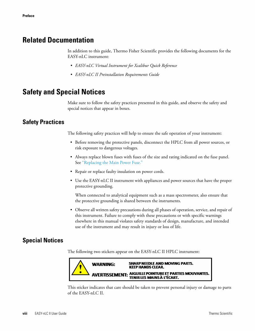
The following two stickers appear on the EASY-nLC II HPLC instrument:
This sticker indicates that care should be taken to prevent personal injury or damage to parts of the EASY-nLC II.
Preface
Thermo Scientific EASY-nLC II User Guide ix
This sticker alerts you to consult this manual for instructions on how to operate the HPLC.
The safety and special notices in the documentation include the following:
Contacting UsThere are several ways to contact Thermo Fisher Scientific for the information you need.
To contact Technical Support
Find software updates and utilities to download at mssupport.thermo.com.
To copy manuals from the Internet
Go to mssupport.thermo.com and click Customer Manuals in the left margin of the window.
CAUTION Highlights hazards to humans, property, or the environment. Each CAUTION notice is accompanied by an appropriate CAUTION symbol.
IMPORTANT Highlights information necessary to prevent damage to software, loss of data, or invalid test results; or may contain information that is critical for optimal performance of the system.
Note Highlights information of general interest.
Tip Highlights helpful information that can make a task easier.
Fax (+45) 6557 2301
Web site www.proxeon.com/productrange/nano_lc
E-mail [email protected]
Address Thermo Fisher ScientificEdisonsvej 4DK-5000 Odense C
Preface
x EASY-nLC II User Guide Thermo Scientific
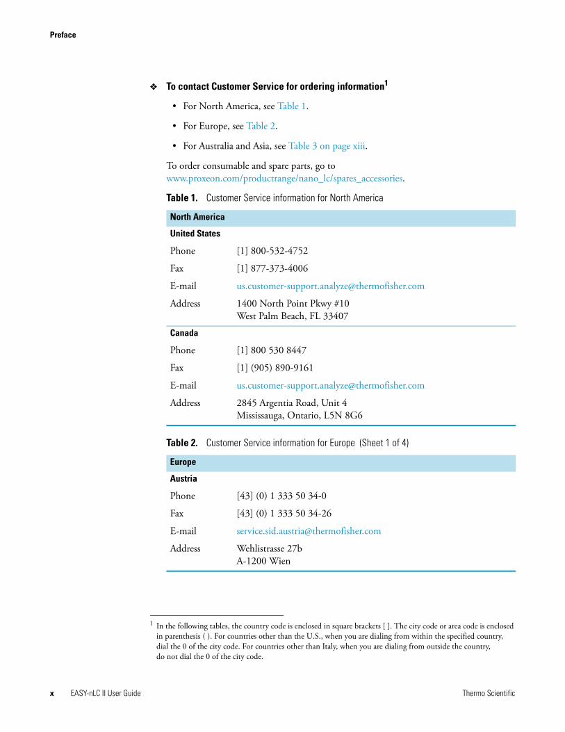
To contact Customer Service for ordering information1
• For North America, see Table 1.
• For Europe, see Table 2.
• For Australia and Asia, see Table 3 on page xiii.
To order consumable and spare parts, go to www.proxeon.com/productrange/nano_lc/spares_accessories.
1 In the following tables, the country code is enclosed in square brackets [ ]. The city code or area code is enclosed in parenthesis ( ). For countries other than the U.S., when you are dialing from within the specified country, dial the 0 of the city code. For countries other than Italy, when you are dialing from outside the country, do not dial the 0 of the city code.
Table 1. Customer Service information for North America
North America
United States
Phone [1] 800-532-4752
Fax [1] 877-373-4006
E-mail [email protected]
Address 1400 North Point Pkwy #10West Palm Beach, FL 33407
Canada
Phone [1] 800 530 8447
Fax [1] (905) 890-9161
E-mail [email protected]
Address 2845 Argentia Road, Unit 4Mississauga, Ontario, L5N 8G6
Table 2. Customer Service information for Europe (Sheet 1 of 4)
Europe
Austria
Phone [43] (0) 1 333 50 34-0
Fax [43] (0) 1 333 50 34-26
E-mail [email protected]
Address Wehlistrasse 27b A-1200 Wien
Preface
Thermo Scientific EASY-nLC II User Guide xi
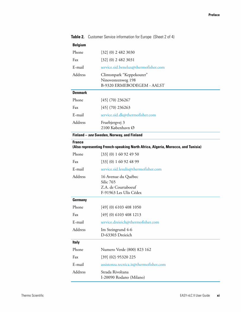
Belgium
Phone [32] (0) 2 482 3030
Fax [32] (0) 2 482 3031
E-mail [email protected]
Address Clintonpark “Keppekouter”Ninovesteenweg 198B-9320 ERMEBODEGEM - AALST
Denmark
Phone [45] (70) 236267
Fax [45] (70) 236263
E-mail [email protected]
Address Fruebjergvej 32100 København Ø
Finland – see Sweden, Norway, and Finland
France (Also representing French-speaking North Africa, Algeria, Morocco, and Tunisia)
Phone [33] (0) 1 60 92 49 50
Fax [33] (0) 1 60 92 48 99
E-mail [email protected]
Address 16 Avenue du QuébecSilic 765Z.A. de CourtaboeufF-91963 Les Ulis Cédex
Germany
Phone [49] (0) 6103 408 1050
Fax [49] (0) 6103 408 1213
E-mail [email protected]
Address Im Steingrund 4-6D-63303 Dreieich
Italy
Phone Numero Verde (800) 823 162
Fax [39] (02) 95320 225
E-mail [email protected]
Address Strada Rivoltana I-20090 Rodano (Milano)
Table 2. Customer Service information for Europe (Sheet 2 of 4)

Preface
xii EASY-nLC II User Guide Thermo Scientific
Netherlands
Phone [31] (0) 76 579 55 55
Fax [31] (0) 76 581 09 61
E-mail [email protected]
Address Takkebijsters 1NL-4817 BL Breda
Norway – see Sweden, Norway, and Finland
Spain
Phone [34] (914) 845 965
Fax [34] (914) 843 598
E-mail [email protected]
Address C/Valportillo I, no22 1a PlantaEdificio CaobaES-28108 Alcobendas - Madrid
Sweden, Norway, and Finland
Phone [46] (0) 8 556 468 20
Fax [46] (0) 8 556 468 08
E-mail [email protected]
Address Pyramidbacken 3S-141 75 Kungens Kurva (Stockholm)Sweden
Switzerland
Phone [41] (617) 16 77 40
Fax [41] (617) 16 77 20
E-mail [email protected]
Address Neuhofstrasse 114153 Reinach
Table 2. Customer Service information for Europe (Sheet 3 of 4)

Preface
Thermo Scientific EASY-nLC II User Guide xiii
United Kingdom
Phone [44] (0) 870 241 1034
Fax [44] (0) 1442 233 667
E-mail [email protected]
Address Stafford House1 Boundary ParkBoundary WayHemel Hempstead Hertfordshire HP2 7GE
Table 3. Customer Service information for Australia and Asia (Sheet 1 of 2)
Australia and Asia
Australia
Phone [61] 39757 4300
Fax [61] 9763 1169
E-mail [email protected]
Address P.O. Box 90925 Caribbean DriveScoresby, VIC 3179
Japan
Phone [81] (45) 453-9100
Fax [81] (45) 453-9110
E-mail [email protected]
Address C-2F 3-9 Moriya-cho, Kanagawa-kuYokohama 221-0022
P.R. China
Phone (free lines) 800 810 5118, 400 650 5118
Fax [86] 10 88370548
E-mail [email protected]
Address 7th Floor, 7F Tower West, Younghe PlazaNo. 28, Andingmen East StreetBeijing 100007
Table 2. Customer Service information for Europe (Sheet 4 of 4)
Preface
xiv EASY-nLC II User Guide Thermo Scientific
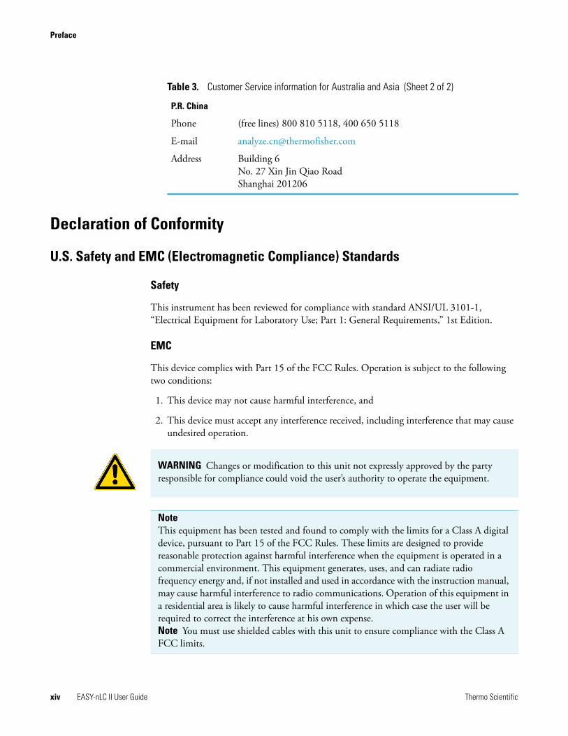
Declaration of Conformity
U.S. Safety and EMC (Electromagnetic Compliance) Standards
Safety
This instrument has been reviewed for compliance with standard ANSI/UL 3101-1, “Electrical Equipment for Laboratory Use; Part 1: General Requirements,” 1st Edition.
EMC
This device complies with Part 15 of the FCC Rules. Operation is subject to the following two conditions:
1. This device may not cause harmful interference, and
2. This device must accept any interference received, including interference that may cause undesired operation.
P.R. China
Phone (free lines) 800 810 5118, 400 650 5118
E-mail [email protected]
Address Building 6No. 27 Xin Jin Qiao RoadShanghai 201206
Table 3. Customer Service information for Australia and Asia (Sheet 2 of 2)
WARNING Changes or modification to this unit not expressly approved by the party responsible for compliance could void the user’s authority to operate the equipment.
Note This equipment has been tested and found to comply with the limits for a Class A digital device, pursuant to Part 15 of the FCC Rules. These limits are designed to provide reasonable protection against harmful interference when the equipment is operated in a commercial environment. This equipment generates, uses, and can radiate radio frequency energy and, if not installed and used in accordance with the instruction manual, may cause harmful interference to radio communications. Operation of this equipment in a residential area is likely to cause harmful interference in which case the user will be required to correct the interference at his own expense.Note You must use shielded cables with this unit to ensure compliance with the Class A FCC limits.
Preface
Thermo Scientific EASY-nLC II User Guide xv
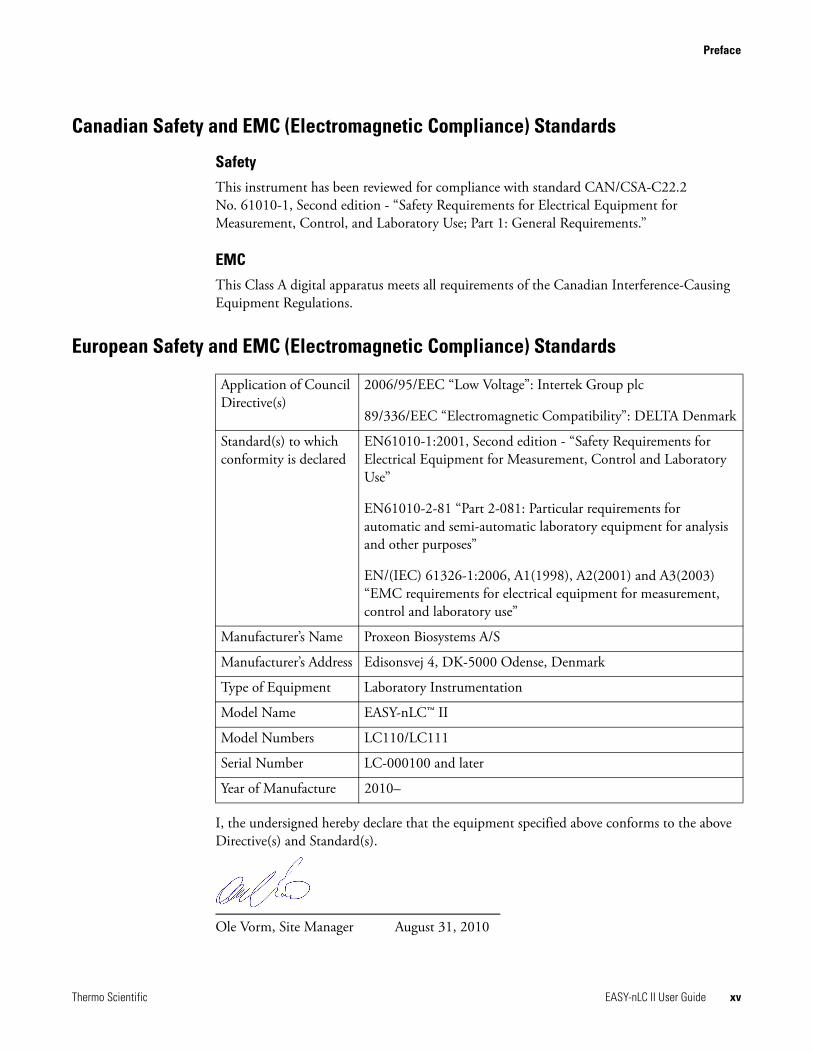
Canadian Safety and EMC (Electromagnetic Compliance) Standards
Safety
This instrument has been reviewed for compliance with standard CAN/CSA-C22.2 No. 61010-1, Second edition - “Safety Requirements for Electrical Equipment for Measurement, Control, and Laboratory Use; Part 1: General Requirements.”
EMC
This Class A digital apparatus meets all requirements of the Canadian Interference-Causing Equipment Regulations.
European Safety and EMC (Electromagnetic Compliance) Standards
I, the undersigned hereby declare that the equipment specified above conforms to the above Directive(s) and Standard(s).
Ole Vorm, Site Manager August 31, 2010
Application of Council Directive(s)
2006/95/EEC “Low Voltage”: Intertek Group plc
89/336/EEC “Electromagnetic Compatibility”: DELTA Denmark
Standard(s) to which conformity is declared
EN61010-1:2001, Second edition - “Safety Requirements for Electrical Equipment for Measurement, Control and Laboratory Use”
EN61010-2-81 “Part 2-081: Particular requirements for automatic and semi-automatic laboratory equipment for analysis and other purposes”
EN/(IEC) 61326-1:2006, A1(1998), A2(2001) and A3(2003) “EMC requirements for electrical equipment for measurement, control and laboratory use”
Manufacturer’s Name Proxeon Biosystems A/S
Manufacturer’s Address Edisonsvej 4, DK-5000 Odense, Denmark
Type of Equipment Laboratory Instrumentation
Model Name EASY-nLC™ II
Model Numbers LC110/LC111
Serial Number LC-000100 and later
Year of Manufacture 2010–

Thermo Scientific EASY-nLC II User Guide 1
1
Introduction
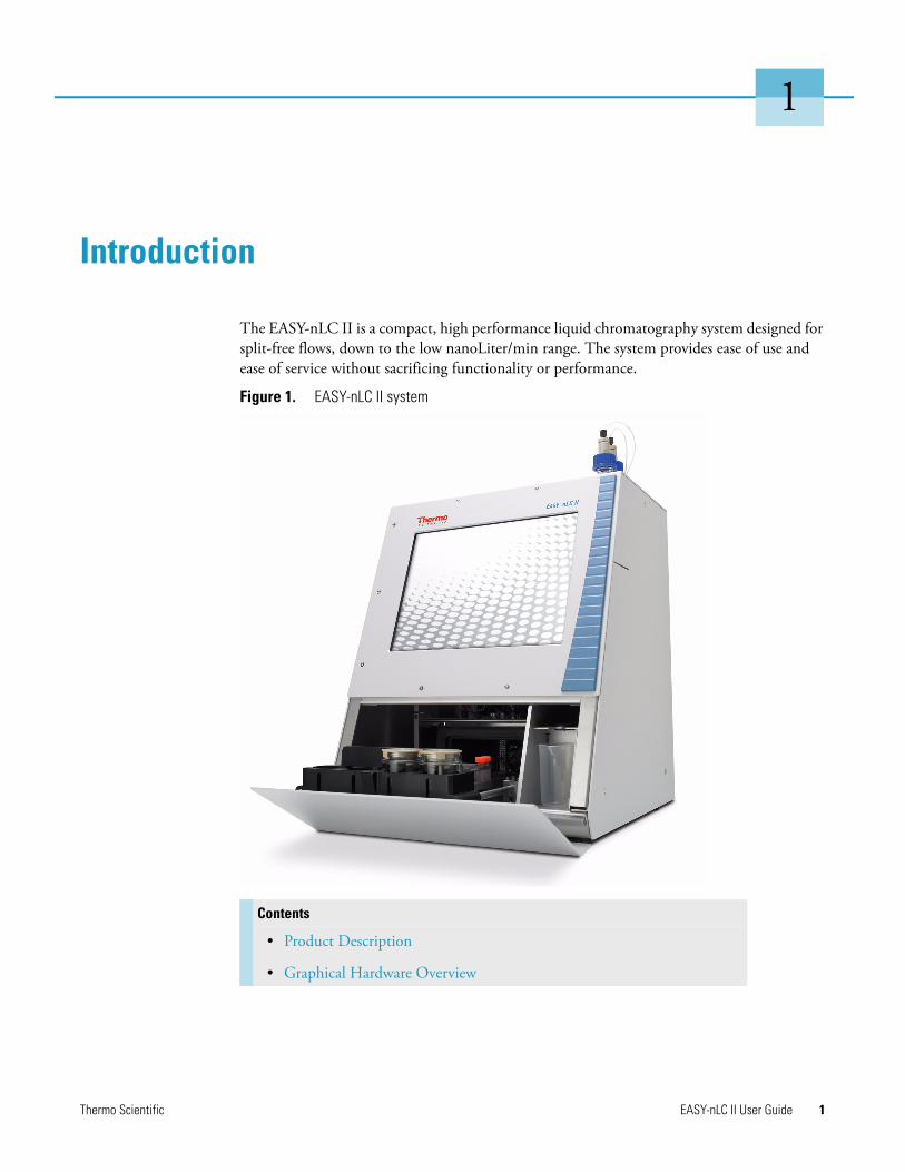
The EASY-nLC II is a compact, high performance liquid chromatography system designed for split-free flows, down to the low nanoLiter/min range. The system provides ease of use and ease of service without sacrificing functionality or performance.
Figure 1. EASY-nLC II system
Contents
• Product Description
• Graphical Hardware Overview
1 IntroductionProduct Description
2 EASY-nLC II User Guide Thermo Scientific
Product DescriptionIn the EASY-nLC II system, all necessary components are integrated into one simple, compact unit, making installation easy: connect the power cable and a network cable (if needed) and turn on the power. An embedded computer controls the system and provides an intuitive HPLC interface using an integrated touch-sensitive monitor.
The instrument has a fixed configuration that optimizes the sample handling by using in-depth knowledge of the instrument design and performance characteristics. Instead of having to set up every aspect of a method—from timing to individual control commands—you can enter the parameters that describe the result you want. The software manages the required low-level control.
Furthermore, you can connect the instrument and the integrated computer to the major mass spectrometers and include them in IT schedules for backup procedures and other functions. System maintenance is provided through a range of controlled software, built-in diagnostic tests, and the internal layout of all instrument components.
System Components
The EASY-nLC II system consists of the following components.
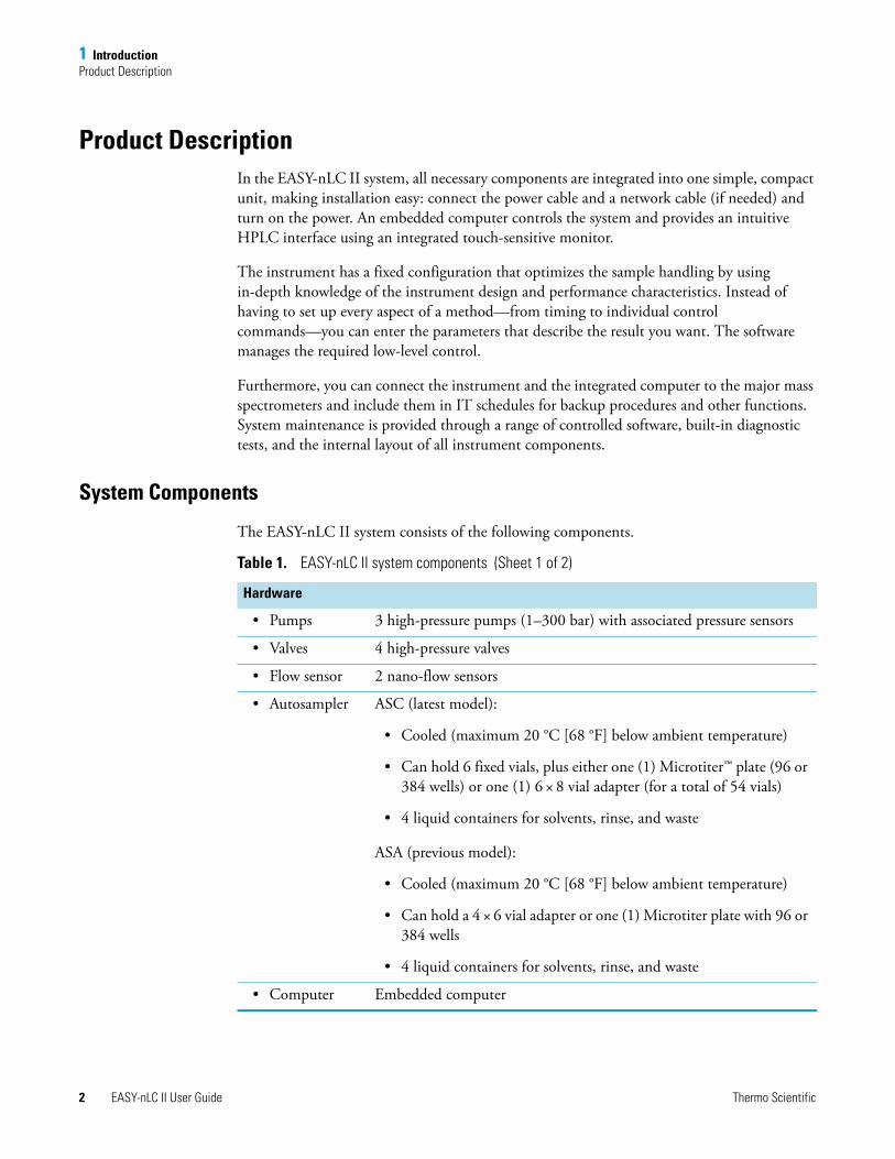
Table 1. EASY-nLC II system components (Sheet 1 of 2)
Hardware
• Pumps 3 high-pressure pumps (1–300 bar) with associated pressure sensors
• Valves 4 high-pressure valves
• Flow sensor 2 nano-flow sensors
• Autosampler ASC (latest model):
• Cooled (maximum 20 °C [68 °F] below ambient temperature)
• Can hold 6 fixed vials, plus either one (1) Microtiter™ plate (96 or 384 wells) or one (1) 6 × 8 vial adapter (for a total of 54 vials)
• 4 liquid containers for solvents, rinse, and waste
ASA (previous model):
• Cooled (maximum 20 °C [68 °F] below ambient temperature)
• Can hold a 4 × 6 vial adapter or one (1) Microtiter plate with 96 or 384 wells
• 4 liquid containers for solvents, rinse, and waste
• Computer Embedded computer

1 IntroductionProduct Description
Thermo Scientific EASY-nLC II User Guide 3
System Configuration for Two-Column Setup
For a two-column setup, the components are connected as shown in Figure 2.
Figure 2. HPLC flow paths for a two-column setup
• Monitor Touch sensitive 12.1 in. (30.7 cm, 800 × 600 pixels) that can be used with gloves
Total size: w 35 cm (14 in.), d 38 cm (15 in.), h 45 cm (18 in.)
Total weight: 32 kg (71 lb)
Utilities: Main power, 120/230 Vac, 50/60 Hz, 250 W
Software
• EASY-nLC II stand-alone application (version 2.8)
Table 1. EASY-nLC II system components (Sheet 2 of 2)
Pump A
Pump B
ValveA
ValveB
ValveS
ValveW
Flowsensor A
Solvent A
Solvent B
Pump S
Precolumn
Autosampler Waste
Flowsensor B
A/B mixing Tee
Sample loop
VendingTee
Analytical column
1 IntroductionProduct Description
4 EASY-nLC II User Guide Thermo Scientific
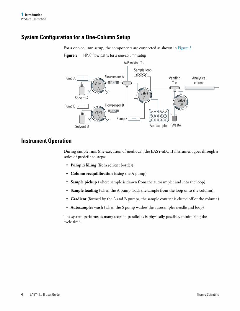
System Configuration for a One-Column Setup
For a one-column setup, the components are connected as shown in Figure 3.
Figure 3. HPLC flow paths for a one-column setup
Instrument Operation
During sample runs (the execution of methods), the EASY-nLC II instrument goes through a series of predefined steps:
• Pump refilling (from solvent bottles)
• Column reequilibration (using the A pump)
• Sample pickup (where sample is drawn from the autosampler and into the loop)
• Sample loading (when the A pump loads the sample from the loop onto the column)
• Gradient (formed by the A and B pumps, the sample content is eluted off of the column)
• Autosampler wash (when the S pump washes the autosampler needle and loop)
The system performs as many steps in parallel as is physically possible, minimizing the cycle time.
Pump A
Pump B
ValveA
ValveB
ValveS
ValveW
Flowsensor A
Solvent A
Solvent B
Pump S
Autosampler Waste
Flowsensor B
VendingTee
Analytical column
A/B mixing Tee
Sample loop
1 IntroductionProduct Description
Thermo Scientific EASY-nLC II User Guide 5
Pump Flow Control
The EASY-nLC II instrument contains split-free, high-pressure syringe pumps capable of delivering flows between 10 nL/min and 300 μL/min (at different resolutions and with different precision). Different flow control systems are active during different method subprocesses (reequilibration, loading, and gradient) to optimize the pumping system performance. The Advanced Flow Control system (AFC™) accurately controls the flow from each pump (A and B pump), providing enhanced gradient control and retention time reproducibility.
During column reequilibration and sample loading, it is more important to actively control the pressure that these processes are performed under than to have precise flow control (needed during gradient elution). To meet this need, you can use the Intelligent Flow Control system (IFC™) to specify an operating pressure rather than a flow.
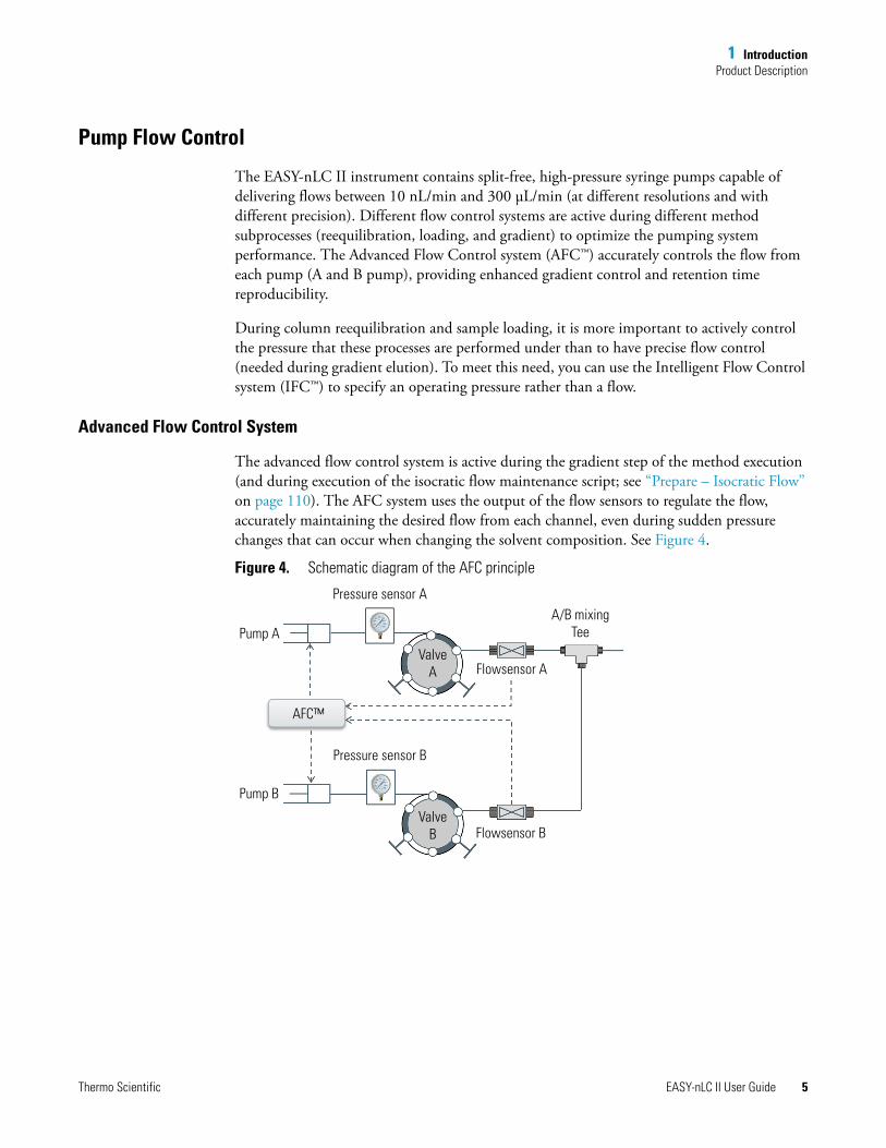
Advanced Flow Control System
The advanced flow control system is active during the gradient step of the method execution (and during execution of the isocratic flow maintenance script; see “Prepare – Isocratic Flow” on page 110). The AFC system uses the output of the flow sensors to regulate the flow, accurately maintaining the desired flow from each channel, even during sudden pressure changes that can occur when changing the solvent composition. See Figure 4.
Figure 4. Schematic diagram of the AFC principle
Pump AValve
A Flowsensor A
Pump B
Pressure sensor A
Pressure sensor B
AFC™
ValveB Flowsensor B
A/B mixing Tee
1 IntroductionProduct Description
6 EASY-nLC II User Guide Thermo Scientific
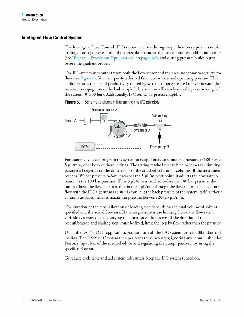
Intelligent Flow Control System
The Intelligent Flow Control (IFC) system is active during reequilibration steps and sample loading, during the execution of the precolumn and analytical column reequilibration scripts (see “Prepare – Precolumn Equilibration” on page 108), and during pressure buildup just before the gradient proper.
The IFC system uses output from both the flow sensor and the pressure sensor to regulate the flow (see Figure 5). You can specify a desired flow rate or a desired operating pressure. This ability reduces the loss of productivity caused by system stoppage related to overpressure (for instance, stoppage caused by bad samples). It also more effectively uses the pressure range of the system (0–300 bar). Additionally, IFC builds up pressure rapidly.
Figure 5. Schematic diagram illustrating the IFC principle
For example, you can program the system to reequilibrate columns at a pressure of 180 bar, at 5 μL/min, or at both of these settings. The setting reached first (which becomes the limiting parameter) depends on the dimensions of the attached column or columns. If the instrument reaches 180 bar pressure before it reaches the 5 μL/min set point, it adjusts the flow rate to maintain the 180 bar pressure. If the 5 μL/min is reached before the 180 bar pressure, the pump adjusts the flow rate to maintain the 5 μL/min through the flow sensor. The maximum flow with the IFC algorithm is 100 μL/min, but the back pressure of the system itself, without columns attached, reaches maximum pressure between 20–25 μL/min.
The duration of the reequilibration or loading step depends on the total volume of solvent specified and the actual flow rate. If the set pressure is the limiting factor, the flow rate is variable as a consequence, varying the duration of these steps. If the duration of the reequilibration and loading steps must be fixed, limit the step by flow rather than the pressure.
Using the EASY-nLC II application, you can turn off the IFC system for reequilibration and loading. The EASY-nLC system then performs these two steps, ignoring any input in the Max Pressure input box of the method editor and regulating the pumps passively by using the specified flow rate.
To reduce cycle time and aid system robustness, keep the IFC system turned on.
Pump A
Pressure sensor A
Flowsensor A
From pump BIFC™
ValveA
A/B mixing Tee
1 IntroductionGraphical Hardware Overview
Thermo Scientific EASY-nLC II User Guide 7
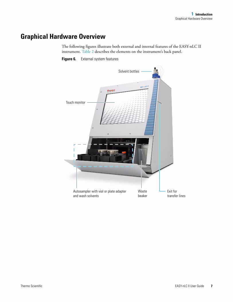
Graphical Hardware OverviewThe following figures illustrate both external and internal features of the EASY-nLC II instrument. Table 2 describes the elements on the instrument’s back panel.
Figure 6. External system features
Touch monitor
Solvent bottles
Waste beaker
Autosampler with vial or plate adapter and wash solvents
Exit for transfer lines
1 IntroductionGraphical Hardware Overview
8 EASY-nLC II User Guide Thermo Scientific
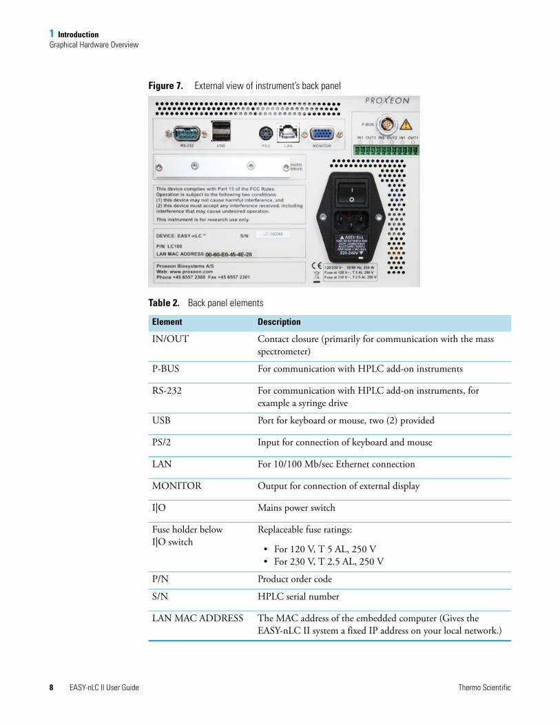
Figure 7. External view of instrument’s back panel
Table 2. Back panel elements
Element Description
IN/OUT Contact closure (primarily for communication with the mass spectrometer)
P-BUS For communication with HPLC add-on instruments
RS-232 For communication with HPLC add-on instruments, for example a syringe drive
USB Port for keyboard or mouse, two (2) provided
PS/2 Input for connection of keyboard and mouse
LAN For 10/100 Mb/sec Ethernet connection
MONITOR Output for connection of external display
I|O Mains power switch
Fuse holder below I|O switch
Replaceable fuse ratings:
• For 120 V, T 5 AL, 250 V• For 230 V, T 2.5 AL, 250 V
P/N Product order code
S/N HPLC serial number
LAN MAC ADDRESS The MAC address of the embedded computer (Gives the EASY-nLC II system a fixed IP address on your local network.)
1 IntroductionGraphical Hardware Overview
Thermo Scientific EASY-nLC II User Guide 9
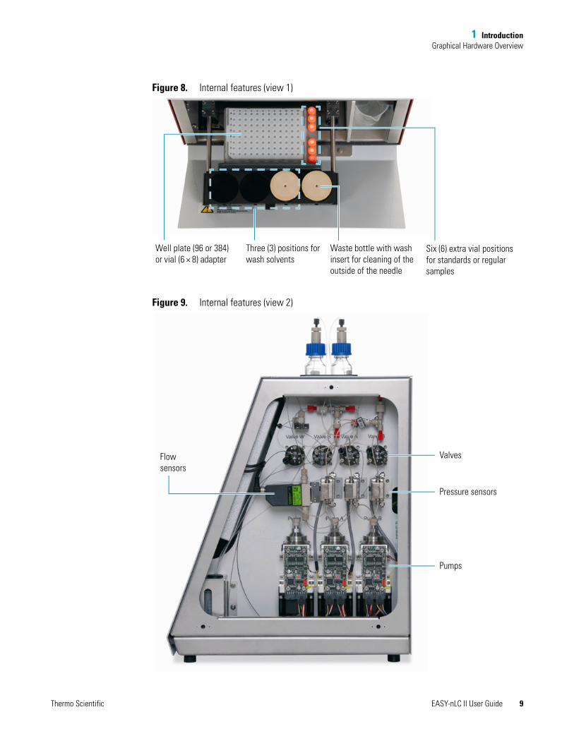
Figure 8. Internal features (view 1)
Figure 9. Internal features (view 2)
Six (6) extra vial positions for standards or regular samples
Waste bottle with wash insert for cleaning of the outside of the needle
Well plate (96 or 384) or vial (6 × 8) adapter
Three (3) positions for wash solvents
Valves
Pressure sensors
Pumps
Flow sensors
1 IntroductionGraphical Hardware Overview
10 EASY-nLC II User Guide Thermo Scientific
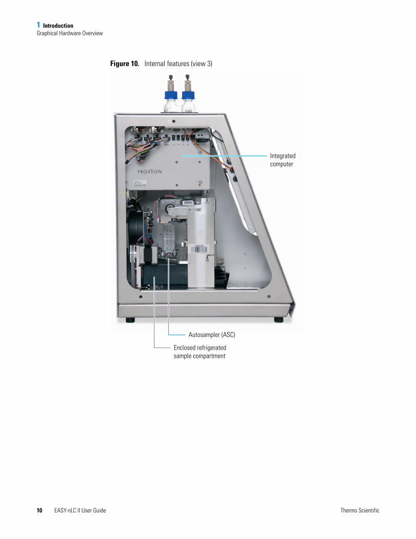
Figure 10. Internal features (view 3)
Integrated computer
Autosampler (ASC)
Enclosed refrigerated sample compartment
Thermo Scientific EASY-nLC II User Guide 11
2
Installation
The following sections provide important information on installing the Thermo Scientific EASY-nLC II instrument. Be sure to review the “Safety and Special Notices” on page viii before proceeding.
PlacementThe EASY-nLC II instrument weighs approximately 32 kg (71 lb) and its dimensions are approximately w 35 × d 38 × h 45 cm (w 14 × d 15 × h 18 in.). Allow for at least 15 cm (6 in.) of free space at the back of the instrument for proper air circulation.
PowerUse this instrument only with properly grounded appliances and power sources.
120 Vac, 50/60 Hz, 250 W230 Vac, 50/60 Hz, 250 W
(For UPS dimensioning, assume 250 W)
For 120 Vac: one T 5 AL 250 V fuse (5 × 20 mm, IEC 60127)For 230 Vac: one T 2.5 AL 250 V fuse
All fuses supplied with the instrument are UL Listed and CSA-certified.
Contents
• Placement
• Power
• Temperature and Humidity
• Lifting Instruction
• External Connections
• Flow Parts and Lines
2 InstallationTemperature and Humidity
12 EASY-nLC II User Guide Thermo Scientific
Temperature and HumidityAvoid locations with high air humidity or extreme changes in temperature (such as direct sunlight, drafts, or directly below an air conditioning or heating vent). Place the EASY-nLC II instrument as close as possible to the detector and mass spectrometer to minimize dead volume in the transfer lines. Place the EASY-nLC II system away from any detector/mass spectrometer vents, however, to avoid exposure to direct heat.
For optimal autosampler plate cooling, place the unit in an area where the working temperature is within 5–30 °C (41–86 °F) .
The optimal humidity range is between 20–80% RH. Avoid condensing humidity.
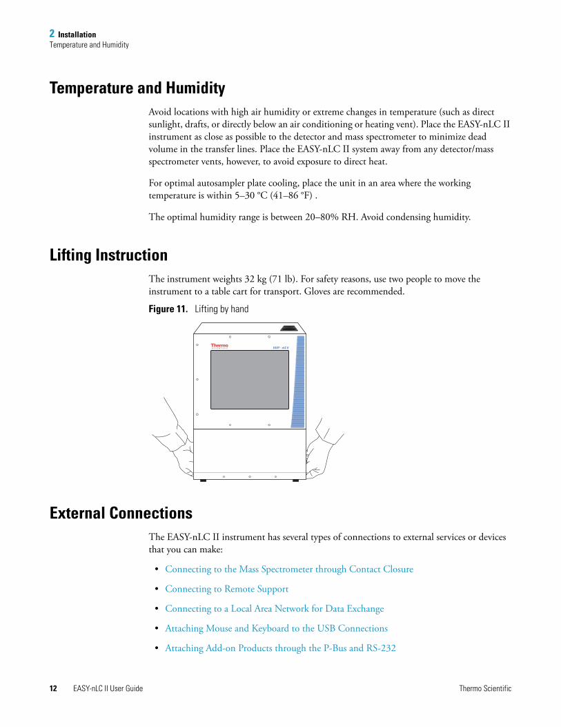
Lifting InstructionThe instrument weights 32 kg (71 lb). For safety reasons, use two people to move the instrument to a table cart for transport. Gloves are recommended.
Figure 11. Lifting by hand
External ConnectionsThe EASY-nLC II instrument has several types of connections to external services or devices that you can make:
• Connecting to the Mass Spectrometer through Contact Closure
• Connecting to Remote Support
• Connecting to a Local Area Network for Data Exchange
• Attaching Mouse and Keyboard to the USB Connections
• Attaching Add-on Products through the P-Bus and RS-232
EASY - nLC II
2 InstallationExternal Connections
Thermo Scientific EASY-nLC II User Guide 13
Connecting to the Mass Spectrometer through Contact Closure
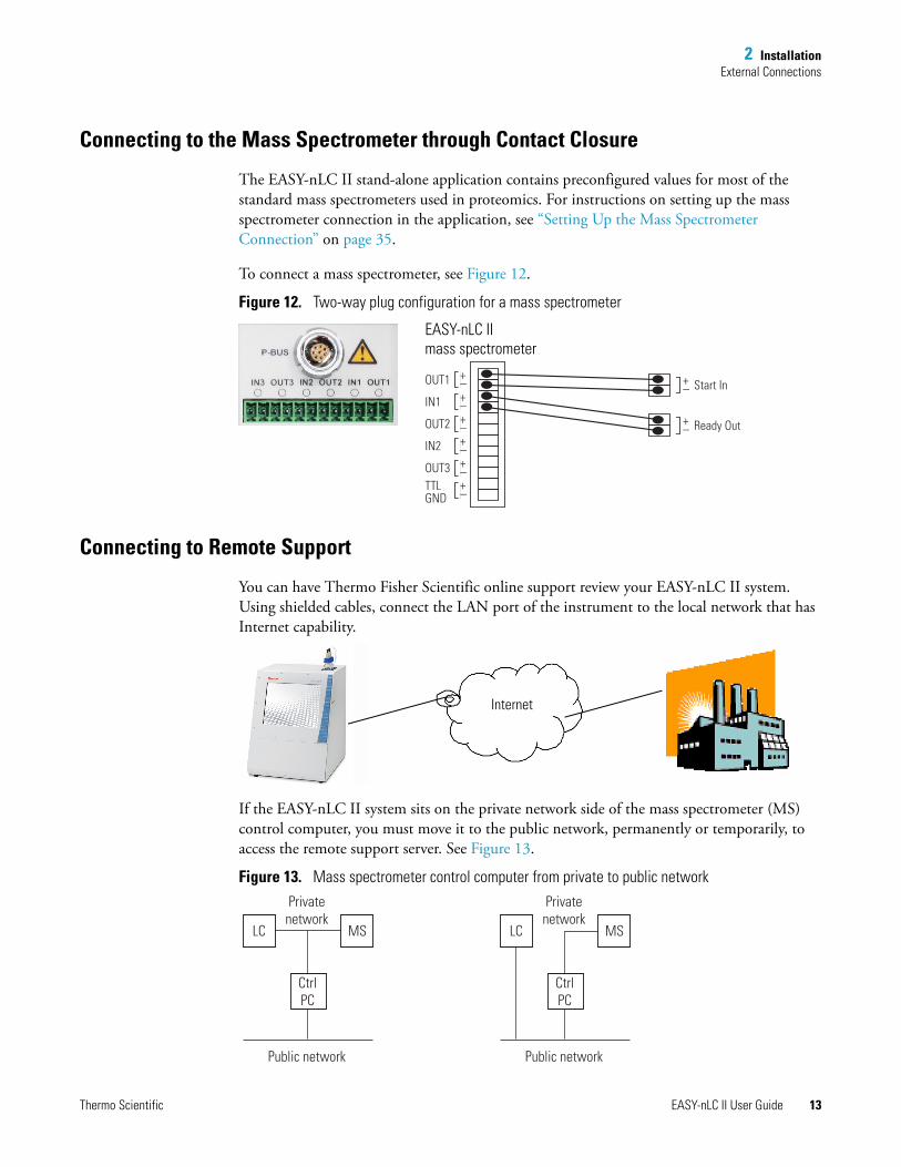
The EASY-nLC II stand-alone application contains preconfigured values for most of the standard mass spectrometers used in proteomics. For instructions on setting up the mass spectrometer connection in the application, see “Setting Up the Mass Spectrometer Connection” on page 35.
To connect a mass spectrometer, see Figure 12.
Figure 12. Two-way plug configuration for a mass spectrometer
Connecting to Remote Support
You can have Thermo Fisher Scientific online support review your EASY-nLC II system. Using shielded cables, connect the LAN port of the instrument to the local network that has Internet capability.
If the EASY-nLC II system sits on the private network side of the mass spectrometer (MS) control computer, you must move it to the public network, permanently or temporarily, to access the remote support server. See Figure 13.
Figure 13. Mass spectrometer control computer from private to public network
OUT1
IN1
OUT2
IN2
OUT3TTLGND
+_ +_ Start In
+_ Ready Out
+_+_+_+_+_
EASY-nLC IImass spectrometer
Internet
Privatenetwork
Public network
LC MS
CtrlPC
Privatenetwork
Public network
LC MS
CtrlPC
2 InstallationExternal Connections
14 EASY-nLC II User Guide Thermo Scientific
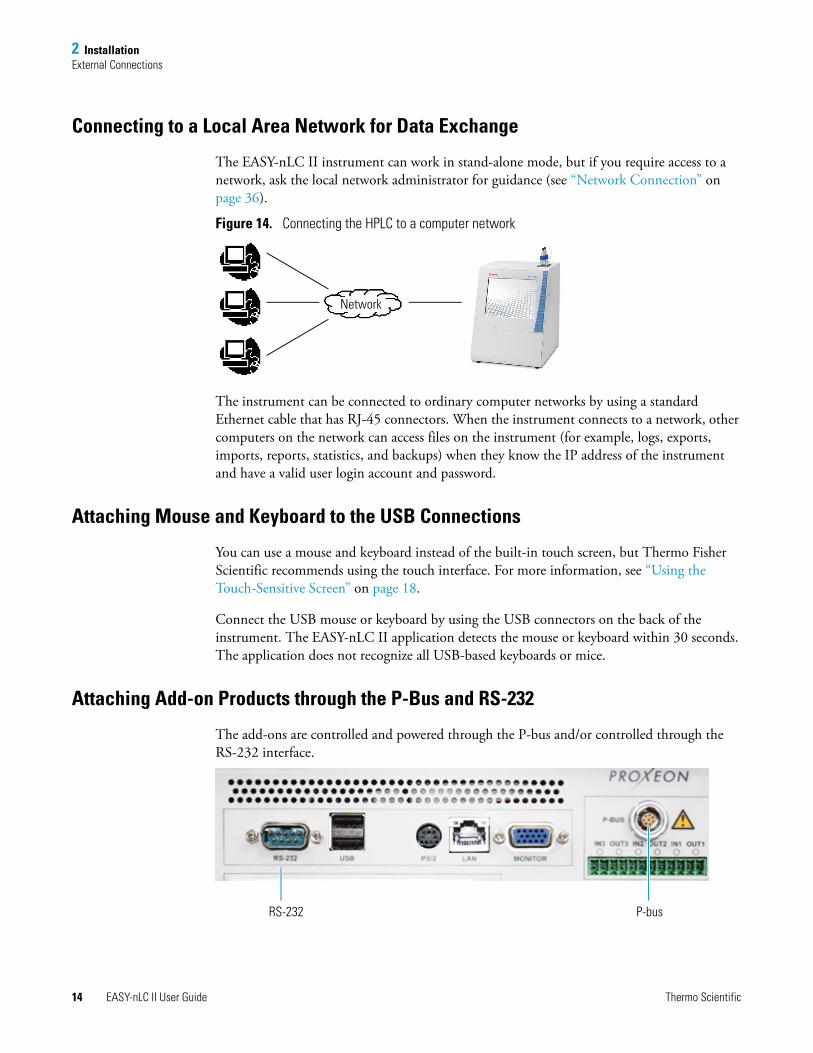
Connecting to a Local Area Network for Data Exchange
The EASY-nLC II instrument can work in stand-alone mode, but if you require access to a network, ask the local network administrator for guidance (see “Network Connection” on page 36).
Figure 14. Connecting the HPLC to a computer network
The instrument can be connected to ordinary computer networks by using a standard Ethernet cable that has RJ-45 connectors. When the instrument connects to a network, other computers on the network can access files on the instrument (for example, logs, exports, imports, reports, statistics, and backups) when they know the IP address of the instrument and have a valid user login account and password.
Attaching Mouse and Keyboard to the USB Connections
You can use a mouse and keyboard instead of the built-in touch screen, but Thermo Fisher Scientific recommends using the touch interface. For more information, see “Using the Touch-Sensitive Screen” on page 18.
Connect the USB mouse or keyboard by using the USB connectors on the back of the instrument. The EASY-nLC II application detects the mouse or keyboard within 30 seconds. The application does not recognize all USB-based keyboards or mice.
Attaching Add-on Products through the P-Bus and RS-232
The add-ons are controlled and powered through the P-bus and/or controlled through the RS-232 interface.
Network
RS-232 P-bus
2 InstallationFlow Parts and Lines
Thermo Scientific EASY-nLC II User Guide 15
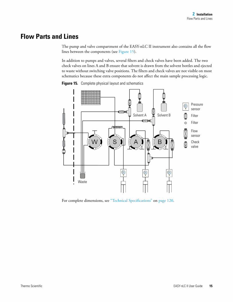
Flow Parts and LinesThe pump and valve compartment of the EASY-nLC II instrument also contains all the flow lines between the components (see Figure 15).
In addition to pumps and valves, several filters and check valves have been added. The two check valves on lines A and B ensure that solvent is drawn from the solvent bottles and ejected to waste without switching valve positions. The filters and check valves are not visible on most schematics because these extra components do not affect the main sample processing logic.
Figure 15. Complete physical layout and schematics
For complete dimensions, see “Technical Specifications” on page 120.
Pressure sensor
Filter
Filter
Flowsensor
Checkvalve
Solvent BSolvent A
Waste

Thermo Scientific EASY-nLC II User Guide 17
3
Instrument Control Software
The EASY-nLC II instrument is controlled by software that runs on an integrated computer; this eliminates the need for a dedicated computer next to the instrument. This chapter provides basic instructions for the reliable and efficient operation of the EASY-nLC II system.
The application presents an easy-to-use interface for defining methods (sample processing protocols), scheduling batches for execution (on a Microtiter-plate basis), following the system progress and status, managing users, and carrying out maintenance and repair work.
Contents
• Using the Touch-Sensitive Screen
• Starting the EASY-nLC II System
• User Interface Layout
• General Interaction Principles
• Application Menu Structure
• Logging In to the EASY-nLC II System
• Closing Down the EASY-nLC II System
3 Instrument Control SoftwareUsing the Touch-Sensitive Screen
18 EASY-nLC II User Guide Thermo Scientific
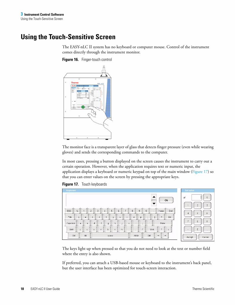
Using the Touch-Sensitive ScreenThe EASY-nLC II system has no keyboard or computer mouse. Control of the instrument comes directly through the instrument monitor.
Figure 16. Finger-touch control
The monitor face is a transparent layer of glass that detects finger pressure (even while wearing gloves) and sends the corresponding commands to the computer.
In most cases, pressing a button displayed on the screen causes the instrument to carry out a certain operation. However, when the application requires text or numeric input, the application displays a keyboard or numeric keypad on top of the main window (Figure 17) so that you can enter values on the screen by pressing the appropriate keys.
Figure 17. Touch keyboards
The keys light up when pressed so that you do not need to look at the text or number field where the entry is also shown.
If preferred, you can attach a USB-based mouse or keyboard to the instrument’s back panel, but the user interface has been optimized for touch-screen interaction.
EASY - nLC II
3 Instrument Control SoftwareStarting the EASY-nLC II System
Thermo Scientific EASY-nLC II User Guide 19
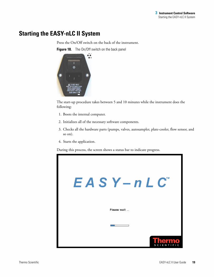
Starting the EASY-nLC II SystemPress the On/Off switch on the back of the instrument.
Figure 18. The On/Off switch on the back panel
The start-up procedure takes between 5 and 10 minutes while the instrument does the following:
1. Boots the internal computer.
2. Initializes all of the necessary software components.
3. Checks all the hardware parts (pumps, valves, autosampler, plate-cooler, flow sensor, and so on).
4. Starts the application.
During this process, the screen shows a status bar to indicate progress.
3 Instrument Control SoftwareUser Interface Layout
20 EASY-nLC II User Guide Thermo Scientific
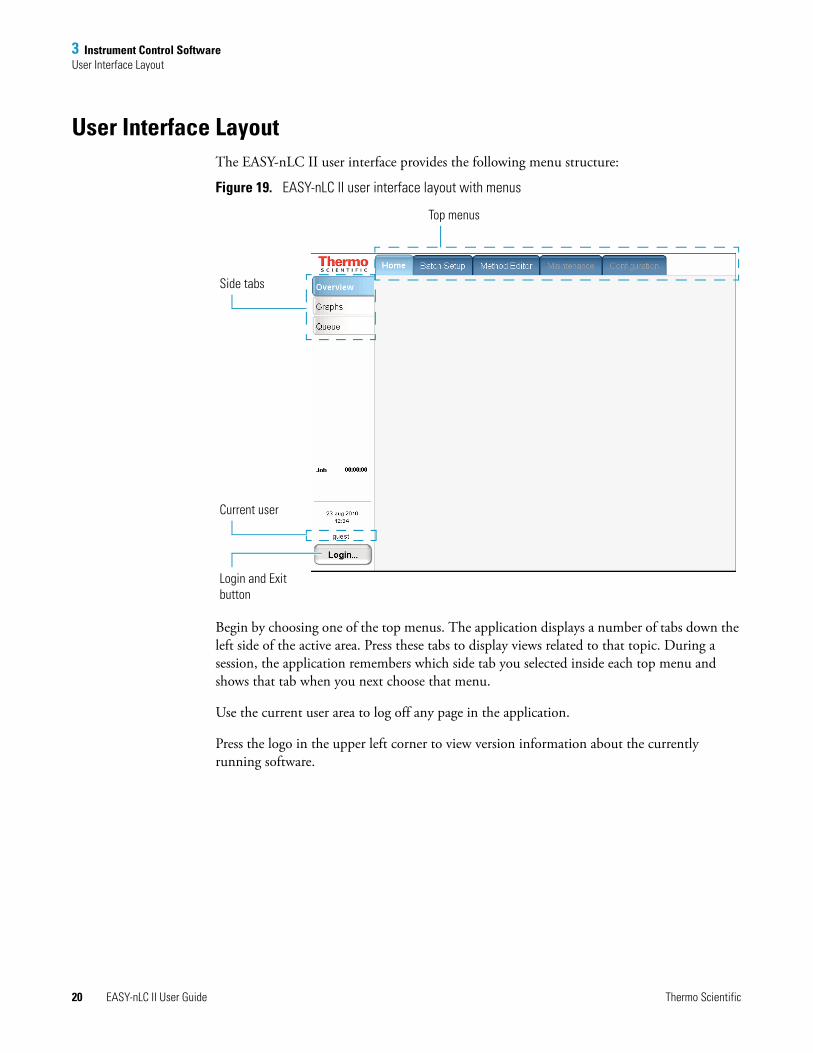
User Interface LayoutThe EASY-nLC II user interface provides the following menu structure:
Figure 19. EASY-nLC II user interface layout with menus
Begin by choosing one of the top menus. The application displays a number of tabs down the left side of the active area. Press these tabs to display views related to that topic. During a session, the application remembers which side tab you selected inside each top menu and shows that tab when you next choose that menu.
Use the current user area to log off any page in the application.
Press the logo in the upper left corner to view version information about the currently running software.
Top menus
Current user
Login and Exit button
Side tabs
3 Instrument Control SoftwareGeneral Interaction Principles
Thermo Scientific EASY-nLC II User Guide 21
General Interaction PrinciplesPress buttons only one time for a specific action. If the action is important or irreversible, the EASY-nLC II application displays a confirmation dialog box so that you can cancel the action.
You can edit many tables (usually when you have entered the data yourself ). You can also access single cells by touching the cell twice to open a keyboard/keypad display for changing the entry.
Long tables have vertical scroll bars that you move either by pressing the up or down arrow symbols, or by dragging the scroll bar and moving it explicitly.
In some tables you can select multiple rows by pressing check boxes on several rows or complete columns by pressing the table headings.
If a screen has blank input fields, press inside the field to enter data. The application displays a keyboard/keypad.
Many button actions provide a confirmation box where the user is prompted to either accept or cancel an action.
In the rest of this guide, we use the menu/left side area to refer to a given screen, accessed first by pressing the top menu tab and then by pressing the appropriate side tab (for example Home > Queue).
Application Menu StructureThe EASY-nLC II application has five top menus:
• Home
• Batch Setup
• Method Editor
• Maintenance
• Configuration
3 Instrument Control SoftwareApplication Menu Structure
22 EASY-nLC II User Guide Thermo Scientific
Home
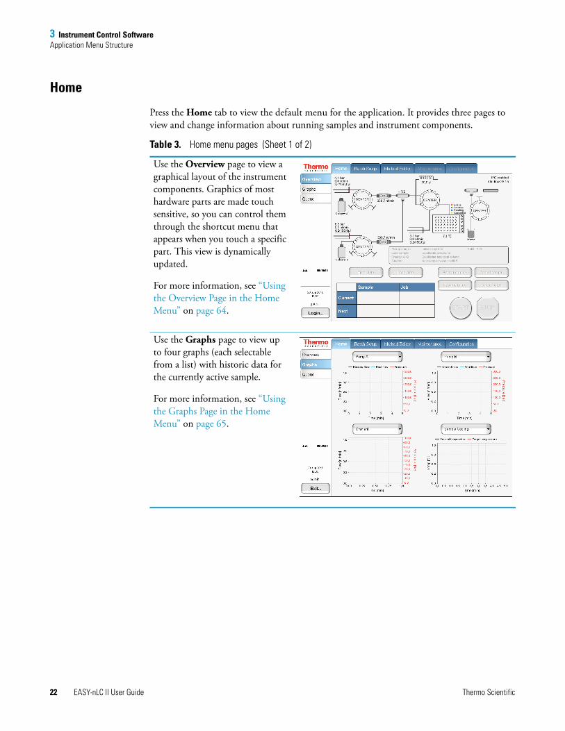
Press the Home tab to view the default menu for the application. It provides three pages to view and change information about running samples and instrument components.
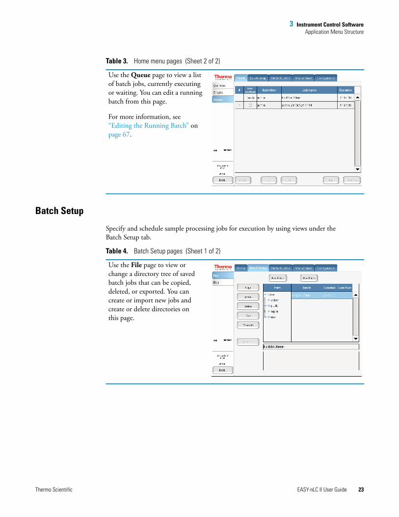
Table 3. Home menu pages (Sheet 1 of 2)
Use the Overview page to view a graphical layout of the instrument components. Graphics of most hardware parts are made touch sensitive, so you can control them through the shortcut menu that appears when you touch a specific part. This view is dynamically updated.
For more information, see “Using the Overview Page in the Home Menu” on page 64.
Use the Graphs page to view up to four graphs (each selectable from a list) with historic data for the currently active sample.
For more information, see “Using the Graphs Page in the Home Menu” on page 65.
3 Instrument Control SoftwareApplication Menu Structure
Thermo Scientific EASY-nLC II User Guide 23
Batch Setup
Specify and schedule sample processing jobs for execution by using views under the Batch Setup tab.
Use the Queue page to view a list of batch jobs, currently executing or waiting. You can edit a running batch from this page.
For more information, see “Editing the Running Batch” on page 67.
Table 3. Home menu pages (Sheet 2 of 2)
Table 4. Batch Setup pages (Sheet 1 of 2)
Use the File page to view or change a directory tree of saved batch jobs that can be copied, deleted, or exported. You can create or import new jobs and create or delete directories on this page.
3 Instrument Control SoftwareApplication Menu Structure
24 EASY-nLC II User Guide Thermo Scientific
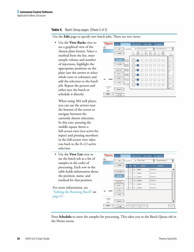
Press Schedule to enter the samples for processing. This takes you to the Batch Queue tab in the Home menu.
Use the Edit page to specify new batch jobs. There are two views:
• Use the View Racks view to see a graphical view of the chosen plate format. Select a method from the list, enter sample volume and number of injections, highlight the appropriate positions on the plate (use the arrows to select whole rows or columns) and add the selection to the batch job. Repeat the process and either save the batch or schedule it directly.
When using 384 well plates, you can use the arrows near the bottom of the screen to navigate between the currently shown selections. In this case, pressing the middle square shows a full-screen view (not active for input) and pressing anywhere in the full-screen view takes you back to the 8 ×12 active selection.
• Use the View List view to see the batch job as a list of samples in the order of processing. Each row in the table holds information about the position, name, and method for that position.
For more information, see “Editing the Running Batch” on page 67.
Table 4. Batch Setup pages (Sheet 2 of 2)
3 Instrument Control SoftwareApplication Menu Structure
Thermo Scientific EASY-nLC II User Guide 25
Method Editor
Press the Method Editor tab to define sample processing methods.
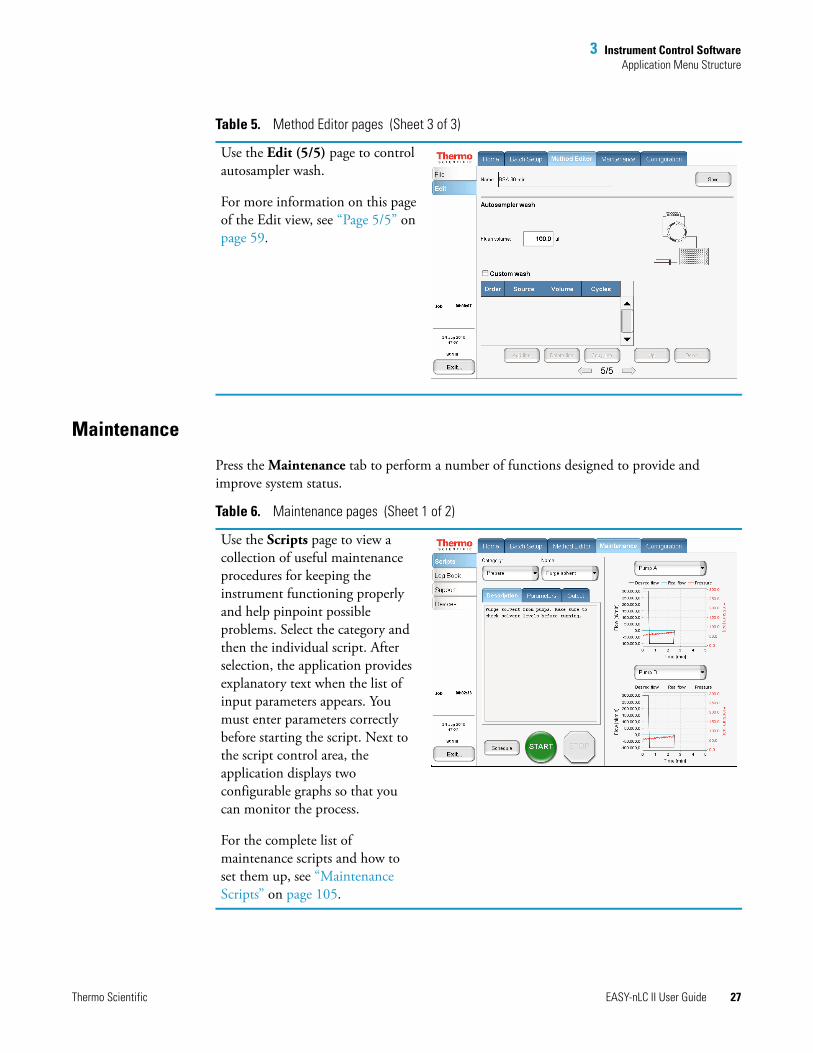
Table 5. Method Editor pages (Sheet 1 of 3)
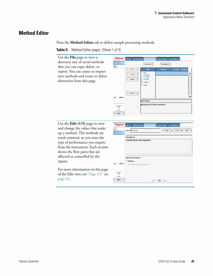
Use the File page to view a directory tree of saved methods that you can copy, delete, or export. You can create or import new methods and create or delete directories from this page.
Use the Edit (1/5) page to view and change the values that make up a method. The methods are result oriented, so you state the type of performance you require from the instrument. Each section shows the flow parts that are affected or controlled by the inputs.
For more information on this page of the Edit view, see “Page 1/5” on page 54.
3 Instrument Control SoftwareApplication Menu Structure
26 EASY-nLC II User Guide Thermo Scientific
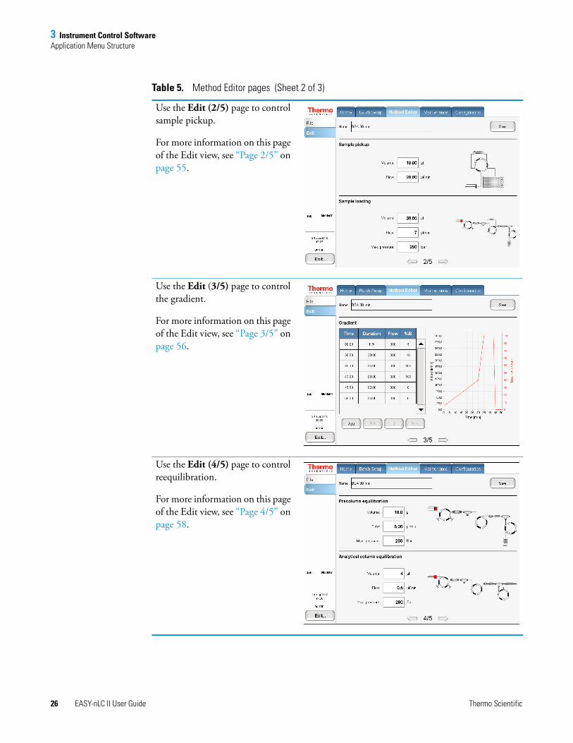
Use the Edit (2/5) page to control sample pickup.
For more information on this page of the Edit view, see “Page 2/5” on page 55.
Use the Edit (3/5) page to control the gradient.
For more information on this page of the Edit view, see “Page 3/5” on page 56.
Use the Edit (4/5) page to control reequilibration.
For more information on this page of the Edit view, see “Page 4/5” on page 58.
Table 5. Method Editor pages (Sheet 2 of 3)
3 Instrument Control SoftwareApplication Menu Structure
Thermo Scientific EASY-nLC II User Guide 27
Maintenance
Press the Maintenance tab to perform a number of functions designed to provide and improve system status.
Use the Edit (5/5) page to control autosampler wash.
For more information on this page of the Edit view, see “Page 5/5” on page 59.
Table 5. Method Editor pages (Sheet 3 of 3)
Table 6. Maintenance pages (Sheet 1 of 2)
Use the Scripts page to view a collection of useful maintenance procedures for keeping the instrument functioning properly and help pinpoint possible problems. Select the category and then the individual script. After selection, the application provides explanatory text when the list of input parameters appears. You must enter parameters correctly before starting the script. Next to the script control area, the application displays two configurable graphs so that you can monitor the process.
For the complete list of maintenance scripts and how to set them up, see “Maintenance Scripts” on page 105.

3 Instrument Control SoftwareApplication Menu Structure
28 EASY-nLC II User Guide Thermo Scientific
Use the Log Book page to electronically enter all the service actions that have been carried out on the instrument. There is a general log where you can enter general comments about all the components and areas for several specific actions that are used actively in other parts of the application (primarily statistics).
Use the Support page to set up support from Thermo Fisher Scientific. For a more comprehensive description, see Chapter 9, “Remote Support.”
Use the Devices page to view and configure hardware devices (including calibrating the autosampler). You can add instruments to the HPLC, such as the Advion™ RePlay™ device (see “Installing and Using the RePlay External Device” on page 125).
For configuration details and parameter descriptions, see “Configuring Column Setup, Loop Volume, Idle Flow, and IFC” on page 40
Table 6. Maintenance pages (Sheet 2 of 2)

3 Instrument Control SoftwareApplication Menu Structure
Thermo Scientific EASY-nLC II User Guide 29
Configuration
Press the Configuration tab to control the instrument setup and manage system configuration.
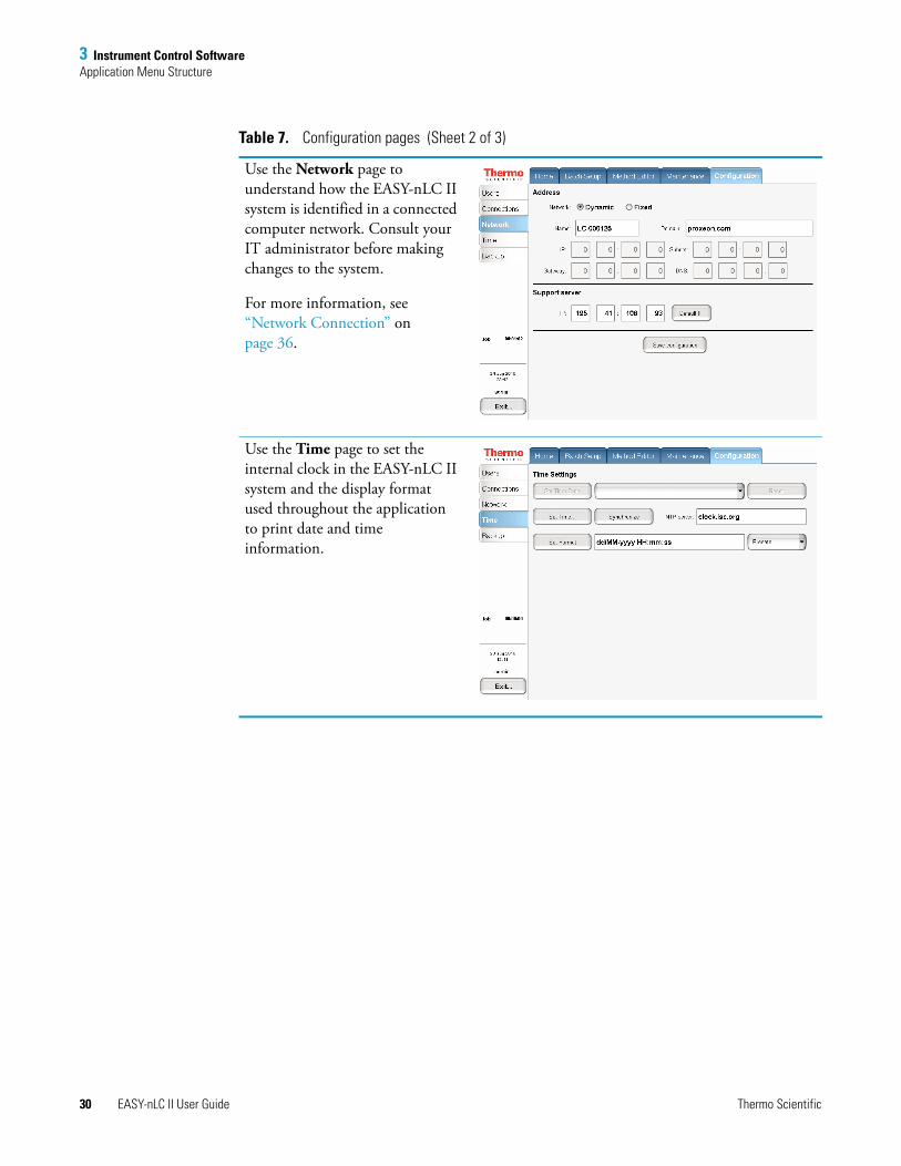
Table 7. Configuration pages (Sheet 1 of 3)
Use the Users page to manage user accounts (create, edit, and delete).
For more information, see “Creating New User Accounts” on page 40.
Use the Connections page to view which mass spectrometer connects to the EASY-nLC II system and how the communication is set up.
For more information, see “Setting Up the Mass Spectrometer Connection” on page 35.
3 Instrument Control SoftwareApplication Menu Structure
30 EASY-nLC II User Guide Thermo Scientific
Use the Network page to understand how the EASY-nLC II system is identified in a connected computer network. Consult your IT administrator before making changes to the system.
For more information, see “Network Connection” on page 36.
Use the Time page to set the internal clock in the EASY-nLC II system and the display format used throughout the application to print date and time information.
Table 7. Configuration pages (Sheet 2 of 3)
3 Instrument Control SoftwareApplication Menu Structure
Thermo Scientific EASY-nLC II User Guide 31
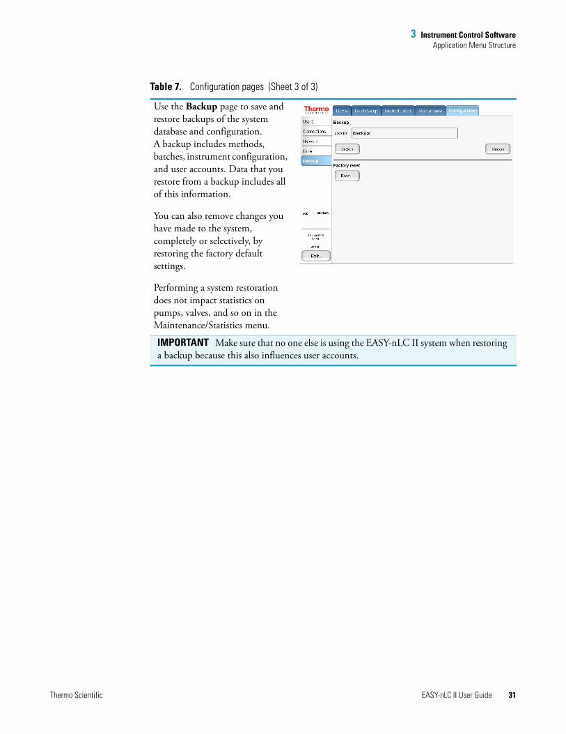
Use the Backup page to save and restore backups of the system database and configuration. A backup includes methods, batches, instrument configuration, and user accounts. Data that you restore from a backup includes all of this information.
You can also remove changes you have made to the system, completely or selectively, by restoring the factory default settings.
Performing a system restoration does not impact statistics on pumps, valves, and so on in the Maintenance/Statistics menu.
IMPORTANT Make sure that no one else is using the EASY-nLC II system when restoring a backup because this also influences user accounts.
Table 7. Configuration pages (Sheet 3 of 3)
3 Instrument Control SoftwareLogging In to the EASY-nLC II System
32 EASY-nLC II User Guide Thermo Scientific
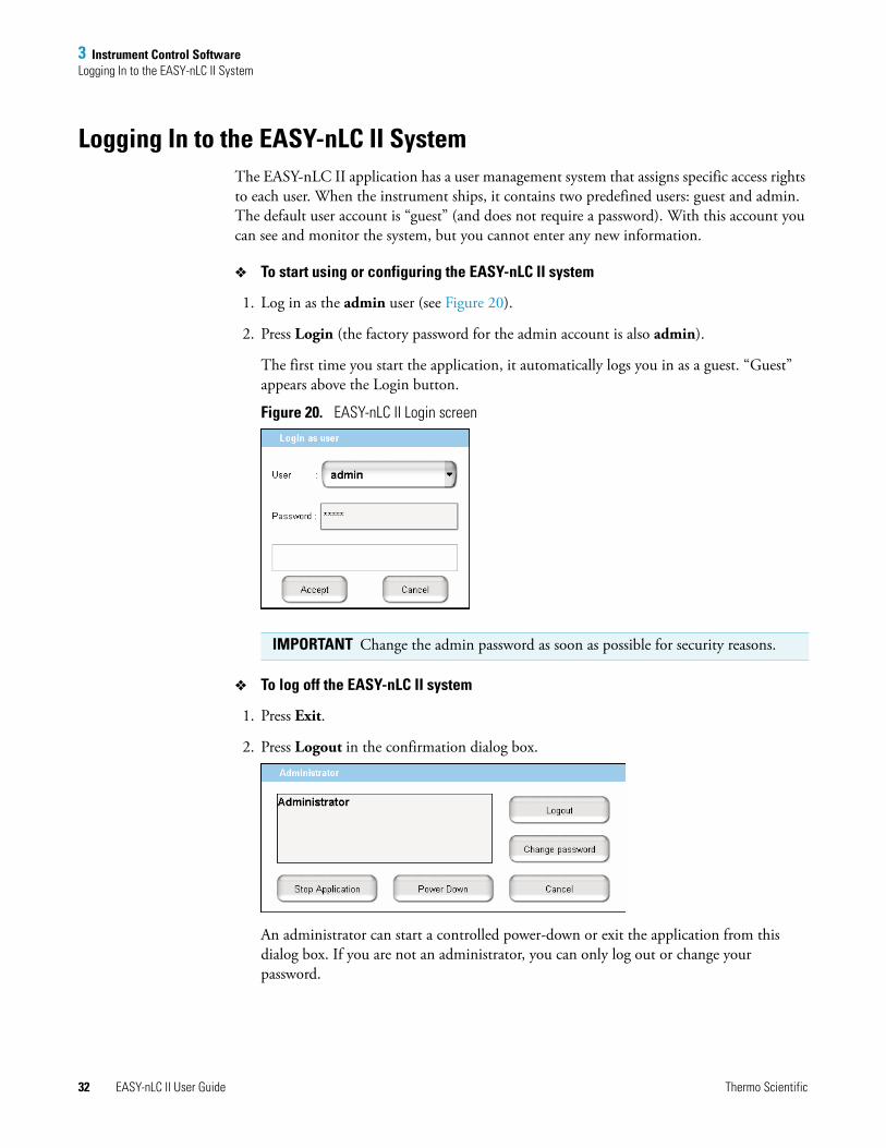
Logging In to the EASY-nLC II SystemThe EASY-nLC II application has a user management system that assigns specific access rights to each user. When the instrument ships, it contains two predefined users: guest and admin. The default user account is “guest” (and does not require a password). With this account you can see and monitor the system, but you cannot enter any new information.
To start using or configuring the EASY-nLC II system
1. Log in as the admin user (see Figure 20).
2. Press Login (the factory password for the admin account is also admin).
The first time you start the application, it automatically logs you in as a guest. “Guest” appears above the Login button.
Figure 20. EASY-nLC II Login screen
To log off the EASY-nLC II system
1. Press Exit.
2. Press Logout in the confirmation dialog box.
An administrator can start a controlled power-down or exit the application from this dialog box. If you are not an administrator, you can only log out or change your password.
IMPORTANT Change the admin password as soon as possible for security reasons.
3 Instrument Control SoftwareClosing Down the EASY-nLC II System
Thermo Scientific EASY-nLC II User Guide 33
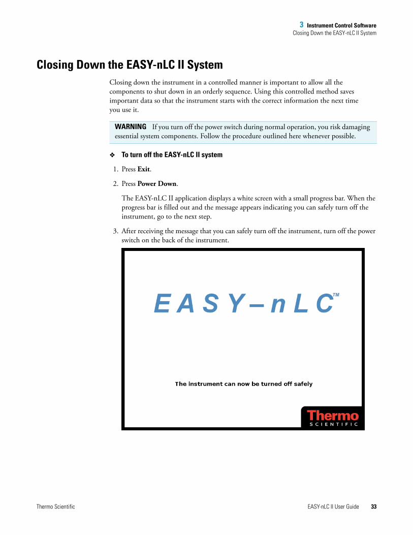
Closing Down the EASY-nLC II SystemClosing down the instrument in a controlled manner is important to allow all the components to shut down in an orderly sequence. Using this controlled method saves important data so that the instrument starts with the correct information the next time you use it.
To turn off the EASY-nLC II system
1. Press Exit.
2. Press Power Down.
The EASY-nLC II application displays a white screen with a small progress bar. When the progress bar is filled out and the message appears indicating you can safely turn off the instrument, go to the next step.
3. After receiving the message that you can safely turn off the instrument, turn off the power switch on the back of the instrument.
WARNING If you turn off the power switch during normal operation, you risk damaging essential system components. Follow the procedure outlined here whenever possible.

Thermo Scientific EASY-nLC II User Guide 35
4
Configuring the EASY-nLC II System
After turning the instrument on and logging on as a system administrator, you must configure the instrument for use and define the work environment between the instrument and computer.
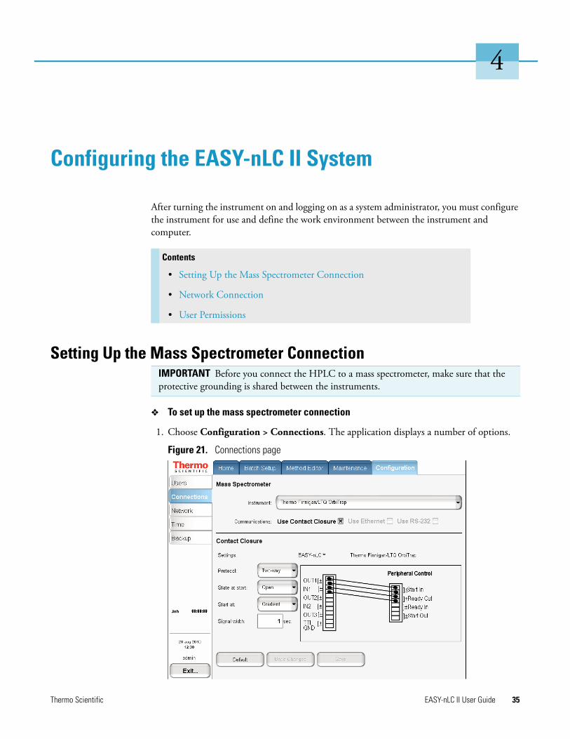
Setting Up the Mass Spectrometer Connection
To set up the mass spectrometer connection
1. Choose Configuration > Connections. The application displays a number of options.
Figure 21. Connections page
Contents
• Setting Up the Mass Spectrometer Connection
• Network Connection
• User Permissions
IMPORTANT Before you connect the HPLC to a mass spectrometer, make sure that the protective grounding is shared between the instruments.
4 Configuring the EASY-nLC II SystemNetwork Connection
36 EASY-nLC II User Guide Thermo Scientific
2. From the Instrument list, select the correct mass spectrometer (see Figure 21). The application comes preconfigured with most of the standard mass spectrometers used in proteomics, but if you cannot find your particular mass spectrometer, select Generic instead.
If your mass spectrometer does not appear on the list and you would like to see it supported in a future release of the EASY-nLC II application, provide this information to Thermo Fisher Scientific Customer Service (see “Contacting Us” on page ix).
3. Ensure that the Use Contact Closure option is selected for the HPLC-mass spectrometer communications protocol.
4. To define contact closure, from the Protocol list select One-way synchronization (see Figure 21)—that is, a simple signal at the start of sample loading or start of gradient.
With a two-way connection, the HPLC waits for an acknowledgement that the mass spectrometer is ready to accept the sample. To correctly set the start state and signal width, refer to the mass spectrometer documentation for how to set up contact closure at the mass spectrometer end.
By setting the Start At value to be the sample loading start, you might be able to acquire data from early-eluting peptides that would not ordinarily bind to the column material and thus be missed from the actual gradient. For this to be effective, you must be running in a one-column system configuration mode.
Network ConnectionYou can access the EASY-nLC II system from other computers (and for remote support) if it is connected to your network.
Note Moving the Start At point to the sample loading start can lead to small retention time variations, due to possible differences in pressure buildup before the A/B mixing starts in the actual gradient.
IMPORTANT Ask your local IT administrator to help you configure the EASY-nLC II system on the local network. The following information will help you through the process.
4 Configuring the EASY-nLC II SystemNetwork Connection
Thermo Scientific EASY-nLC II User Guide 37
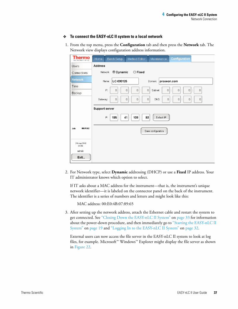
To connect the EASY-nLC II system to a local network
1. From the top menu, press the Configuration tab and then press the Network tab. The Network view displays configuration address information.
2. For Network type, select Dynamic addressing (DHCP) or use a Fixed IP address. Your IT administrator knows which option to select.
If IT asks about a MAC address for the instrument—that is, the instrument’s unique network identifier—it is labeled on the connector panel on the back of the instrument. The identifier is a series of numbers and letters and might look like this:
MAC address: 00:E0:4B:07:89:65
3. After setting up the network address, attach the Ethernet cable and restart the system to get connected. See “Closing Down the EASY-nLC II System” on page 33 for information about the power-down procedure, and then immediately go to “Starting the EASY-nLC II System” on page 19 and “Logging In to the EASY-nLC II System” on page 32.
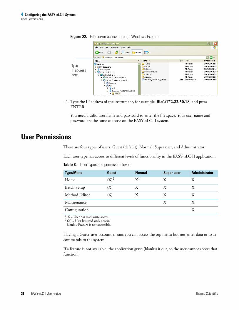
External users can now access the file server in the EASY-nLC II system to look at log files, for example. Microsoft™ Windows™ Explorer might display the file server as shown in Figure 22.
4 Configuring the EASY-nLC II SystemUser Permissions
38 EASY-nLC II User Guide Thermo Scientific
Figure 22. File server access through Windows Explorer
4. Type the IP address of the instrument, for example, file:\\172.22.50.18, and press ENTER.
You need a valid user name and password to enter the file space. Your user name and password are the same as those on the EASY-nLC II system.
User PermissionsThere are four types of users: Guest (default), Normal, Super user, and Administrator.
Each user type has access to different levels of functionality in the EASY-nLC II application.
Having a Guest user account means you can access the top menu but not enter data or issue commands to the system.
If a feature is not available, the application grays (blanks) it out, so the user cannot access that function.
Type IP address here.
Table 8. User types and permission levels
Type/Menu Guest Normal Super user Administrator
Home (X)2 X1 X X
Batch Setup (X) X X X
Method Editor (X) X X X
Maintenance X X
Configuration X1 X = User has read-write access.2 (X) = User has read-only access.Blank = Feature is not accessible.
4 Configuring the EASY-nLC II SystemUser Permissions
Thermo Scientific EASY-nLC II User Guide 39
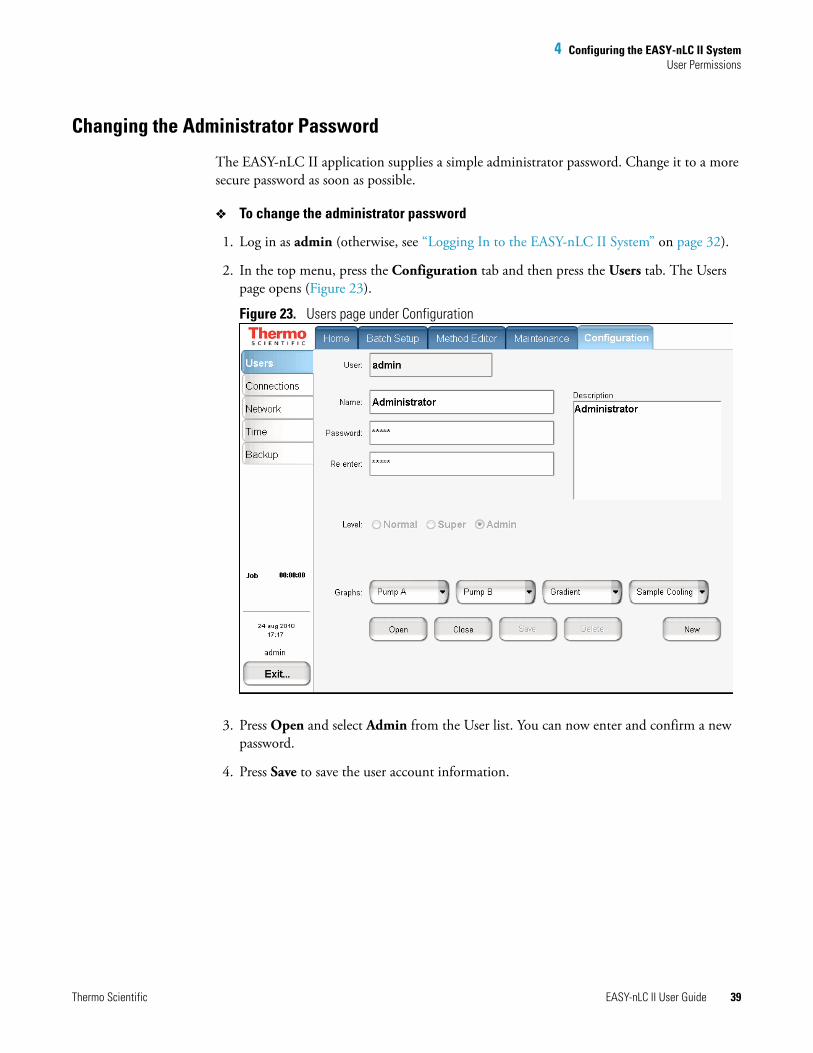
Changing the Administrator Password
The EASY-nLC II application supplies a simple administrator password. Change it to a more secure password as soon as possible.
To change the administrator password
1. Log in as admin (otherwise, see “Logging In to the EASY-nLC II System” on page 32).
2. In the top menu, press the Configuration tab and then press the Users tab. The Users page opens (Figure 23).
Figure 23. Users page under Configuration
3. Press Open and select Admin from the User list. You can now enter and confirm a new password.
4. Press Save to save the user account information.

4 Configuring the EASY-nLC II SystemUser Permissions
40 EASY-nLC II User Guide Thermo Scientific
Creating New User Accounts
Use the Users page to create new user accounts for all the people or groups that will use the instrument. Each user has a private file space for batch jobs and methods that other users (apart from system administrators) cannot see.
In addition, there is a public file space for methods and batch jobs that all users can see and use. Only Super users and Administrators can copy files into the public spaces and only Administrators can delete files and directories from the public space.
To create a new user account
1. Log in as admin (otherwise, see “Logging In to the EASY-nLC II System” on page 32).
2. Choose Configuration > Users. The Users page opens. See Figure 23 on page 39.
3. Press New. Select which privileges to give the new user. For user privileges by user type, see Table 8 on page 38.
If you want the user to carry out instrument maintenance, you must select Super user as the user type. If you want the user to restore data to the system, select Administrator as the user type.
4. Create an initial password for the defined user.
Configuring Column Setup, Loop Volume, Idle Flow, and IFC
Use the Devices page on the Maintenance tab to set global instrument configuration settings such as one- or two-column setup, loop size, idle flow settings, and IFC. For parameter descriptions, see Table 9.
To configure devices
1. Choose Maintenance > Devices.
2. From the Devices list, select EASY-nLC II (HPLC).
Tip Only certain users have access to the Configuration > Users screen to change their own password. All users, however, can change their current password from the Logout confirmation box by pressing Change Password.
Change Password button
4 Configuring the EASY-nLC II SystemUser Permissions
Thermo Scientific EASY-nLC II User Guide 41
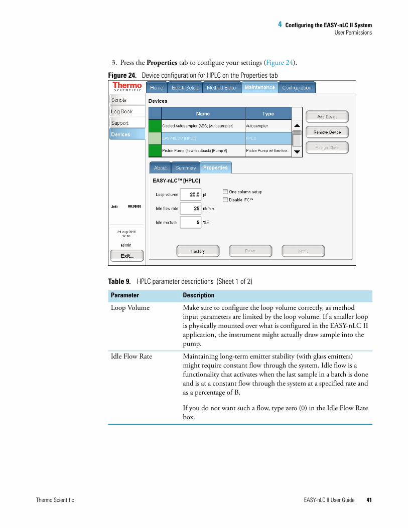
3. Press the Properties tab to configure your settings (Figure 24).
Figure 24. Device configuration for HPLC on the Properties tab
Table 9. HPLC parameter descriptions (Sheet 1 of 2)
Parameter Description
Loop Volume Make sure to configure the loop volume correctly, as method input parameters are limited by the loop volume. If a smaller loop is physically mounted over what is configured in the EASY-nLC II application, the instrument might actually draw sample into the pump.
Idle Flow Rate Maintaining long-term emitter stability (with glass emitters) might require constant flow through the system. Idle flow is a functionality that activates when the last sample in a batch is done and is at a constant flow through the system at a specified rate and as a percentage of B.
If you do not want such a flow, type zero (0) in the Idle Flow Rate box.
4 Configuring the EASY-nLC II SystemUser Permissions
42 EASY-nLC II User Guide Thermo Scientific
One Column Setup You can configure the EASY-nLC II instrument as a one-column or a two-column setup. If the system is operated as a one-column system, you can select its corresponding check box here, and the diagram on the Overview page of the Home menu will reflect this. The actual execution of the method is unaffected by this setting.
Disable IFC For a description of IFC, see “Pump Flow Control” on page 5. You can disable it by selecting this check box.
Table 9. HPLC parameter descriptions (Sheet 2 of 2)
Parameter Description
Thermo Scientific EASY-nLC II User Guide 43
5
Preparation for Use
This chapter describes how to prepare the EASY-nLC II instrument for use.
Log in to the system with either Super user or Administrator privileges. For details, see “Logging In to the EASY-nLC II System” on page 32.
Preparing Solvent Bottles and Waste ContainersBefore shipment, the EASY-nLC II system is flushed with methanol.
Contents
• Preparing Solvent Bottles and Waste Containers
• Executing Maintenance Scripts
• Purging and Flushing the Pumps
• Installing Columns
CAUTION Methanol (CAS number: 67-56-1) is highly flammable, and toxic by inhalation, ingestion, or skin absorption. Take appropriate measures to protect yourself and your equipment. Make sure that the mobile phases are miscible with methanol, or start up with an intermediate solvent as mobile phase.
5 Preparation for UsePreparing Solvent Bottles and Waste Containers
44 EASY-nLC II User Guide Thermo Scientific
Solvent A and B Bottles
Follow these recommended steps for preparing the two solvent bottles.
To prepare the solvent bottles
1. Fill the 25 ml Schott Duran™ blue cap bottles with the mobile phase and degas them either by sonification or by sparging them with helium gas.
2. Place the bottles in the holder on top of the instrument: solvent A bottle in the front and solvent B bottle in the back position.
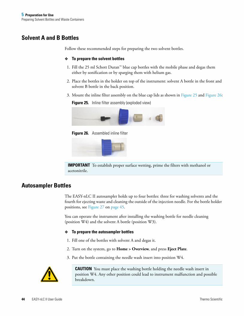
3. Mount the inline filter assembly on the blue cap lids as shown in Figure 25 and Figure 26:
Figure 25. Inline filter assembly (exploded view)
Figure 26. Assembled inline filter
Autosampler Bottles
The EASY-nLC II autosampler holds up to four bottles: three for washing solvents and the fourth for ejecting waste and cleaning the outside of the injection needle. For the bottle holder positions, see Figure 27 on page 45.
You can operate the instrument after installing the washing bottle for needle cleaning (position W4) and the solvent A bottle (position W3).
To prepare the autosampler bottles
1. Fill one of the bottles with solvent A and degas it.
2. Turn on the system, go to Home > Overview, and press Eject Plate.
3. Put the bottle containing the needle wash insert into position W4.
IMPORTANT To establish proper surface wetting, prime the filters with methanol or acetonitrile.
CAUTION You must place the washing bottle holding the needle wash insert in position W4. Any other position could lead to instrument malfunction and possible breakdown.
5 Preparation for UsePreparing Solvent Bottles and Waste Containers
Thermo Scientific EASY-nLC II User Guide 45
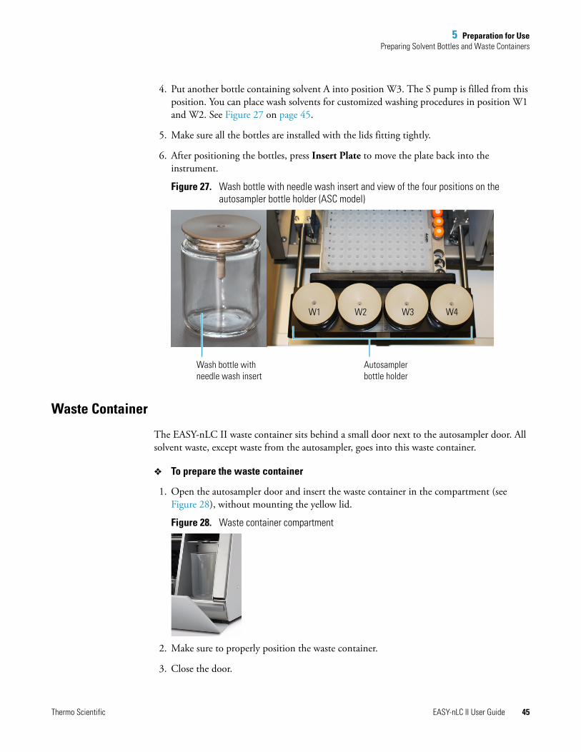
4. Put another bottle containing solvent A into position W3. The S pump is filled from this position. You can place wash solvents for customized washing procedures in position W1 and W2. See Figure 27 on page 45.
5. Make sure all the bottles are installed with the lids fitting tightly.
6. After positioning the bottles, press Insert Plate to move the plate back into the instrument.
Figure 27. Wash bottle with needle wash insert and view of the four positions on the autosampler bottle holder (ASC model)
Waste Container
The EASY-nLC II waste container sits behind a small door next to the autosampler door. All solvent waste, except waste from the autosampler, goes into this waste container.
To prepare the waste container
1. Open the autosampler door and insert the waste container in the compartment (see Figure 28), without mounting the yellow lid.
Figure 28. Waste container compartment
2. Make sure to properly position the waste container.
3. Close the door.
W1 W2 W3 W4
Wash bottle with needle wash insert
Autosampler bottle holder
5 Preparation for UseExecuting Maintenance Scripts
46 EASY-nLC II User Guide Thermo Scientific
Executing Maintenance Scripts
!
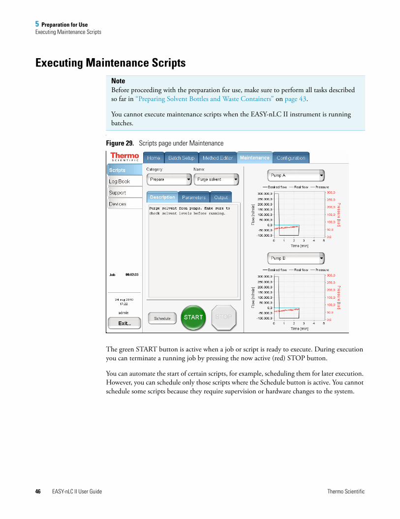
Figure 29. Scripts page under Maintenance
The green START button is active when a job or script is ready to execute. During execution you can terminate a running job by pressing the now active (red) STOP button.
You can automate the start of certain scripts, for example, scheduling them for later execution. However, you can schedule only those scripts where the Schedule button is active. You cannot schedule some scripts because they require supervision or hardware changes to the system.
Note Before proceeding with the preparation for use, make sure to perform all tasks described so far in “Preparing Solvent Bottles and Waste Containers” on page 43.
You cannot execute maintenance scripts when the EASY-nLC II instrument is running batches.
5 Preparation for UsePurging and Flushing the Pumps
Thermo Scientific EASY-nLC II User Guide 47
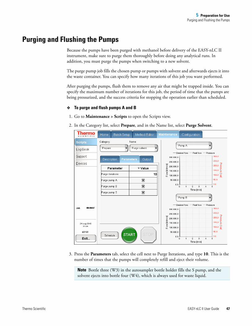
Purging and Flushing the PumpsBecause the pumps have been purged with methanol before delivery of the EASY-nLC II instrument, make sure to purge them thoroughly before doing any analytical runs. In addition, you must purge the pumps when switching to a new solvent.
The purge pump job fills the chosen pump or pumps with solvent and afterwards ejects it into the waste container. You can specify how many iterations of this job you want performed.
After purging the pumps, flush them to remove any air that might be trapped inside. You can specify the maximum number of iterations for this job, the period of time that the pumps are being pressurized, and the success criteria for stopping the operation earlier than scheduled.
To purge and flush pumps A and B
1. Go to Maintenance > Scripts to open the Scripts view.
2. In the Category list, select Prepare, and in the Name list, select Purge Solvent.
3. Press the Parameters tab, select the cell next to Purge Iterations, and type 10. This is the number of times that the pumps will completely refill and eject their volume.
Note Bottle three (W3) in the autosampler bottle holder fills the S pump, and the solvent ejects into bottle four (W4), which is always used for waste liquid.
5 Preparation for UsePurging and Flushing the Pumps
48 EASY-nLC II User Guide Thermo Scientific
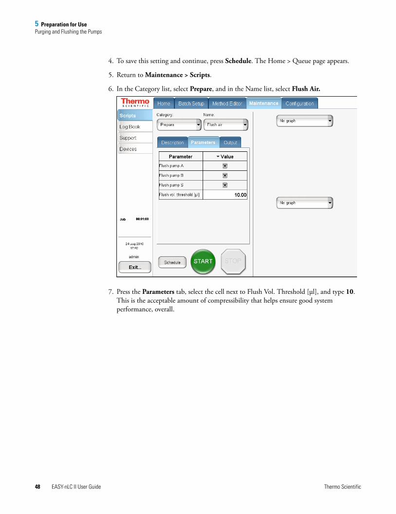
4. To save this setting and continue, press Schedule. The Home > Queue page appears.
5. Return to Maintenance > Scripts.
6. In the Category list, select Prepare, and in the Name list, select Flush Air.
7. Press the Parameters tab, select the cell next to Flush Vol. Threshold [μl], and type 10. This is the acceptable amount of compressibility that helps ensure good system performance, overall.

5 Preparation for UsePurging and Flushing the Pumps
Thermo Scientific EASY-nLC II User Guide 49
8. Press Schedule.
The Home > Queue page appears.
9. In the Jobs list, make sure the check box in the Auto-Continue column is selected for Flush Air.
10. Choose Home > Overview again and press START.
Default graphs are selected in the two graph windows in Maintenance > Scripts, but you may change the selection from the corresponding lists. These graphs help you to monitor the job.
11. Wait for the job to end (the flush air script continues until the flush air volume values are below the specified threshold).
Note While a maintenance job or a script is running, you cannot start other jobs or scripts.
5 Preparation for UseInstalling Columns
50 EASY-nLC II User Guide Thermo Scientific
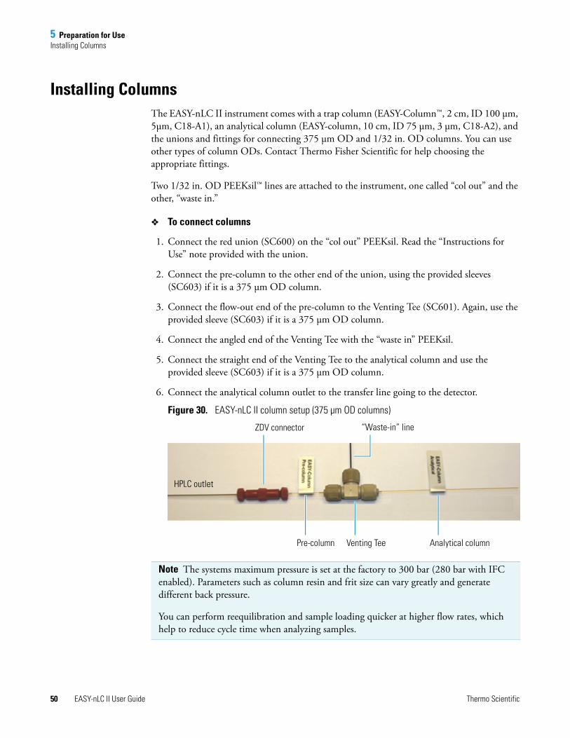
Installing ColumnsThe EASY-nLC II instrument comes with a trap column (EASY-Column™, 2 cm, ID 100 μm, 5μm, C18-A1), an analytical column (EASY-column, 10 cm, ID 75 μm, 3 μm, C18-A2), and the unions and fittings for connecting 375 μm OD and 1/32 in. OD columns. You can use other types of column ODs. Contact Thermo Fisher Scientific for help choosing the appropriate fittings.
Two 1/32 in. OD PEEKsil™ lines are attached to the instrument, one called “col out” and the other, “waste in.”
To connect columns
1. Connect the red union (SC600) on the “col out” PEEKsil. Read the “Instructions for Use” note provided with the union.
2. Connect the pre-column to the other end of the union, using the provided sleeves (SC603) if it is a 375 μm OD column.
3. Connect the flow-out end of the pre-column to the Venting Tee (SC601). Again, use the provided sleeve (SC603) if it is a 375 μm OD column.
4. Connect the angled end of the Venting Tee with the “waste in” PEEKsil.
5. Connect the straight end of the Venting Tee to the analytical column and use the provided sleeve (SC603) if it is a 375 μm OD column.
6. Connect the analytical column outlet to the transfer line going to the detector.
Figure 30. EASY-nLC II column setup (375 μm OD columns)
Note The systems maximum pressure is set at the factory to 300 bar (280 bar with IFC enabled). Parameters such as column resin and frit size can vary greatly and generate different back pressure.
You can perform reequilibration and sample loading quicker at higher flow rates, which help to reduce cycle time when analyzing samples.
“Waste-in” line
Pre-column Venting Tee Analytical column
HPLC outlet
ZDV connector
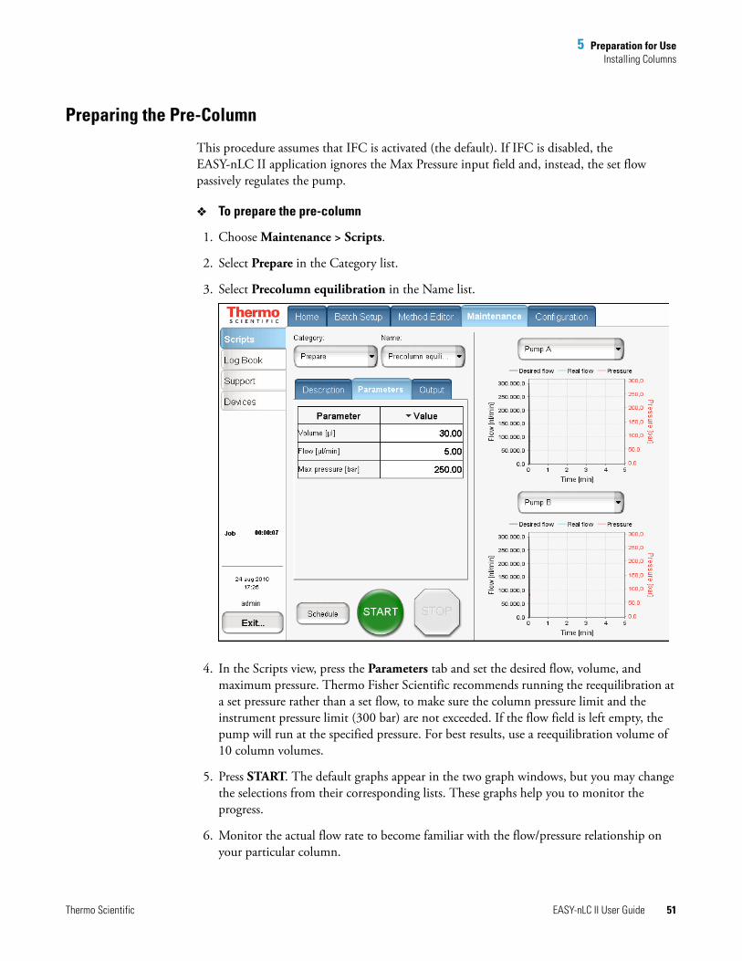
5 Preparation for UseInstalling Columns
Thermo Scientific EASY-nLC II User Guide 51
Preparing the Pre-Column
This procedure assumes that IFC is activated (the default). If IFC is disabled, the EASY-nLC II application ignores the Max Pressure input field and, instead, the set flow passively regulates the pump.
To prepare the pre-column
1. Choose Maintenance > Scripts.
2. Select Prepare in the Category list.
3. Select Precolumn equilibration in the Name list.
4. In the Scripts view, press the Parameters tab and set the desired flow, volume, and maximum pressure. Thermo Fisher Scientific recommends running the reequilibration at a set pressure rather than a set flow, to make sure the column pressure limit and the instrument pressure limit (300 bar) are not exceeded. If the flow field is left empty, the pump will run at the specified pressure. For best results, use a reequilibration volume of 10 column volumes.
5. Press START. The default graphs appear in the two graph windows, but you may change the selections from their corresponding lists. These graphs help you to monitor the progress.
6. Monitor the actual flow rate to become familiar with the flow/pressure relationship on your particular column.
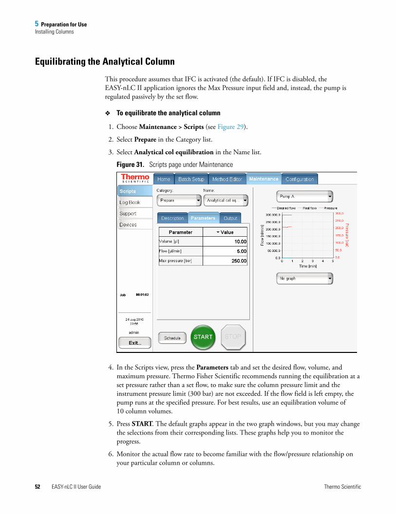
5 Preparation for UseInstalling Columns
52 EASY-nLC II User Guide Thermo Scientific
Equilibrating the Analytical Column
This procedure assumes that IFC is activated (the default). If IFC is disabled, the EASY-nLC II application ignores the Max Pressure input field and, instead, the pump is regulated passively by the set flow.
To equilibrate the analytical column
1. Choose Maintenance > Scripts (see Figure 29).
2. Select Prepare in the Category list.
3. Select Analytical col equilibration in the Name list.
Figure 31. Scripts page under Maintenance
4. In the Scripts view, press the Parameters tab and set the desired flow, volume, and maximum pressure. Thermo Fisher Scientific recommends running the equilibration at a set pressure rather than a set flow, to make sure the column pressure limit and the instrument pressure limit (300 bar) are not exceeded. If the flow field is left empty, the pump runs at the specified pressure. For best results, use an equilibration volume of 10 column volumes.
5. Press START. The default graphs appear in the two graph windows, but you may change the selections from their corresponding lists. These graphs help you to monitor the progress.
6. Monitor the actual flow rate to become familiar with the flow/pressure relationship on your particular column or columns.
Thermo Scientific EASY-nLC II User Guide 53
6
Running the First Sample
This chapter describes how to perform analysis using the EASY-nLC II system. Thermo Fisher Scientific recommends that you quickly start using the application to run additional analytical tests, as practical experience is the most efficient way to understand an instrument such as an HPLC.
Contents
• Preparing a Well Plate
• Creating a Method
• Creating a Batch
• Starting Sample Acquisition
• Monitoring the Run
• Stopping Sample Acquisition
• Editing the Running Batch
• Troubleshooting a Sample Run
6 Running the First SamplePreparing a Well Plate
54 EASY-nLC II User Guide Thermo Scientific
Preparing a Well PlateIf you have not made a plate selection, go to “To select a given plate format” on page 76.
The EASY-nLC II instrument ships with adaptors for vials (56 vials in a 6×8+6 configuration), MTP (96- and 384-well), and PCR strips.
To prepare the well plate
1. Load some vials/wells with your sample, preferably a known standard.
2. Make sure that no air is trapped in the sample vials/wells and that the sample is in the bottom of the vials/wells. To do this, tap the vial/plate gently against a hard surface to have the sample move to the bottom.
3. Put on the vial cap or plate mat.
Creating a MethodThe Edit view under Method Editor consists of five pages to guide you through all the parameters required for a working LC method. The protocol is based on IFC being active (the default system). If you deactivate IFC, the EASY-nLC II application ignores the maximum pressure input fields and instead, the pumps are regulated passively by the set flow (only relevant for sample loading and equilibration steps).
The following sections describe the five pages and guidelines to creating a method.
1. Choose Method Editor > Edit.
2. If you are not already on page 1/5, switch pages by pressing the appropriate arrow near the bottom of the screen.
Page 1/5
To open existing methods and close or save the currently opened method
1. Press SAVE.
2. In the Save File dialog box, press the white box beneath the name.
3. Type method 1 on the keyboard and press OK.
4. Press SAVE in the Save File dialog box.
You may enter a detailed explanation or description in the white text box.
5. Go to page 2/5 by pressing the right arrow.
Note The instrument comes preinstalled with a 20 μL loop. With this loop size, the instrument is capable of picking up sample volumes between 0 and 18 μL.
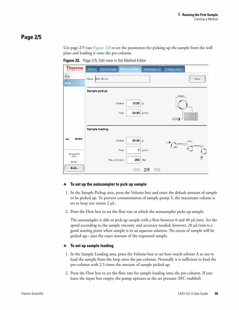
6 Running the First SampleCreating a Method
Thermo Scientific EASY-nLC II User Guide 55
Page 2/5
Use page 2/5 (see Figure 32) to set the parameters for picking up the sample from the well plate and loading it onto the pre-column.
Figure 32. Page 2/5, Edit view in the Method Editor
To set up the autosampler to pick up sample
1. In the Sample Pickup area, press the Volume box and enter the default amount of sample to be picked up. To prevent contamination of sample pump S, the maximum volume is set to loop size minus 2 μL.
2. Press the Flow box to set the flow rate at which the autosampler picks up sample.
The autosampler is able to pick up sample with a flow between 0 and 40 μL/min. Set the speed according to the sample viscosity and accuracy needed; however, 20 μL/min is a good starting point when sample is in an aqueous solution. No excess of sample will be picked up—just the exact amount of the requested sample.
To set up sample loading
1. In the Sample Loading area, press the Volume box to set how much solvent A to use to load the sample from the loop onto the pre-column. Normally it is sufficient to load the pre-column with 2.5 times the amount of sample picked up.
2. Press the Flow box to set the flow rate for sample loading onto the pre-column. If you leave the input box empty, the pump operates at the set pressure (IFC enabled).
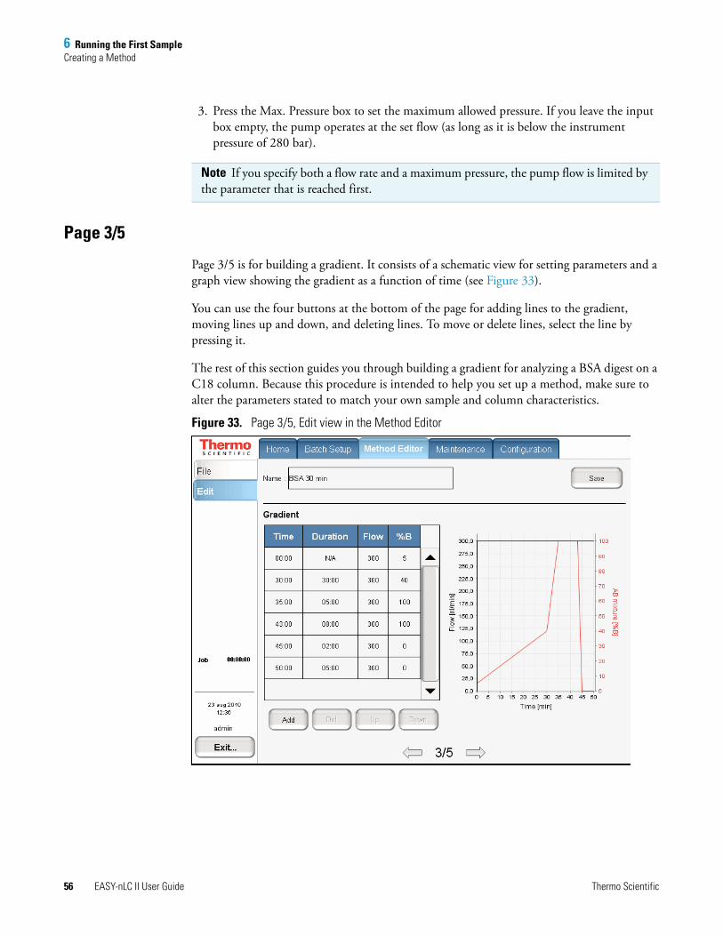
6 Running the First SampleCreating a Method
56 EASY-nLC II User Guide Thermo Scientific
3. Press the Max. Pressure box to set the maximum allowed pressure. If you leave the input box empty, the pump operates at the set flow (as long as it is below the instrument pressure of 280 bar).
Page 3/5
Page 3/5 is for building a gradient. It consists of a schematic view for setting parameters and a graph view showing the gradient as a function of time (see Figure 33).
You can use the four buttons at the bottom of the page for adding lines to the gradient, moving lines up and down, and deleting lines. To move or delete lines, select the line by pressing it.
The rest of this section guides you through building a gradient for analyzing a BSA digest on a C18 column. Because this procedure is intended to help you set up a method, make sure to alter the parameters stated to match your own sample and column characteristics.
Figure 33. Page 3/5, Edit view in the Method Editor
Note If you specify both a flow rate and a maximum pressure, the pump flow is limited by the parameter that is reached first.
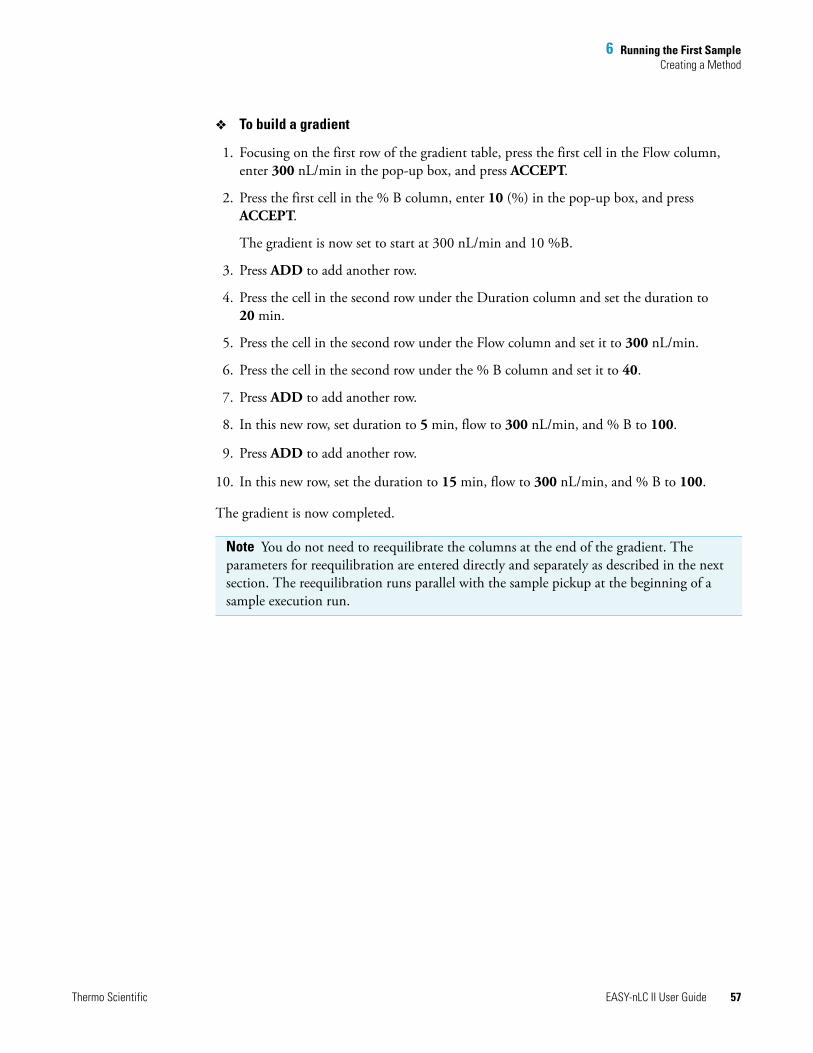
6 Running the First SampleCreating a Method
Thermo Scientific EASY-nLC II User Guide 57
To build a gradient
1. Focusing on the first row of the gradient table, press the first cell in the Flow column, enter 300 nL/min in the pop-up box, and press ACCEPT.
2. Press the first cell in the % B column, enter 10 (%) in the pop-up box, and press ACCEPT.
The gradient is now set to start at 300 nL/min and 10 %B.
3. Press ADD to add another row.
4. Press the cell in the second row under the Duration column and set the duration to 20 min.
5. Press the cell in the second row under the Flow column and set it to 300 nL/min.
6. Press the cell in the second row under the % B column and set it to 40.
7. Press ADD to add another row.
8. In this new row, set duration to 5 min, flow to 300 nL/min, and % B to 100.
9. Press ADD to add another row.
10. In this new row, set the duration to 15 min, flow to 300 nL/min, and % B to 100.
The gradient is now completed.
Note You do not need to reequilibrate the columns at the end of the gradient. The parameters for reequilibration are entered directly and separately as described in the next section. The reequilibration runs parallel with the sample pickup at the beginning of a sample execution run.
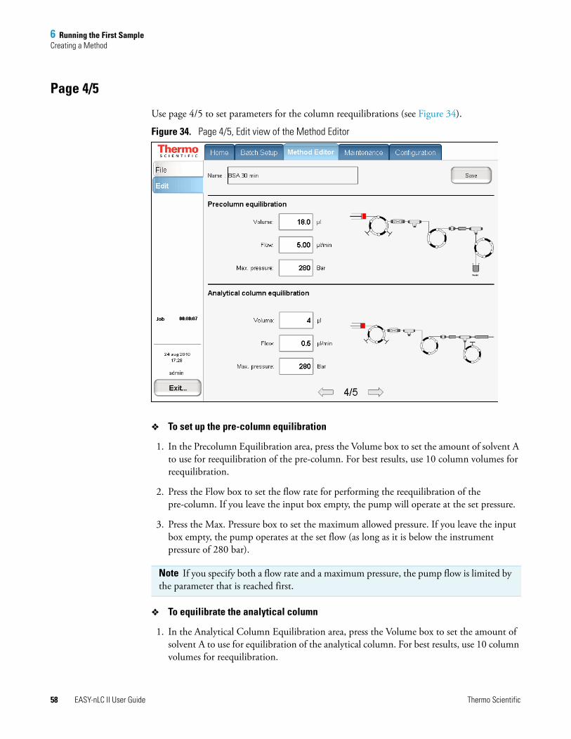
6 Running the First SampleCreating a Method
58 EASY-nLC II User Guide Thermo Scientific
Page 4/5
Use page 4/5 to set parameters for the column reequilibrations (see Figure 34).
Figure 34. Page 4/5, Edit view of the Method Editor
To set up the pre-column equilibration
1. In the Precolumn Equilibration area, press the Volume box to set the amount of solvent A to use for reequilibration of the pre-column. For best results, use 10 column volumes for reequilibration.
2. Press the Flow box to set the flow rate for performing the reequilibration of the pre-column. If you leave the input box empty, the pump will operate at the set pressure.
3. Press the Max. Pressure box to set the maximum allowed pressure. If you leave the input box empty, the pump operates at the set flow (as long as it is below the instrument pressure of 280 bar).
To equilibrate the analytical column
1. In the Analytical Column Equilibration area, press the Volume box to set the amount of solvent A to use for equilibration of the analytical column. For best results, use 10 column volumes for reequilibration.
Note If you specify both a flow rate and a maximum pressure, the pump flow is limited by the parameter that is reached first.
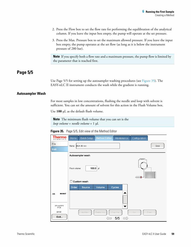
6 Running the First SampleCreating a Method
Thermo Scientific EASY-nLC II User Guide 59
2. Press the Flow box to set the flow rate for performing the equilibration of the analytical column. If you leave the input box empty, the pump will operate at the set pressure.
3. Press the Max. Pressure box to set the maximum allowed pressure. If you leave the input box empty, the pump operates at the set flow (as long as it is below the instrument pressure of 280 bar).
Page 5/5
Use Page 5/5 for setting up the autosampler washing procedures (see Figure 35). The EASY-nLC II instrument conducts the wash while the gradient is running.
Autosampler Wash
For most samples in low concentrations, flushing the needle and loop with solvent is sufficient. You can set the amount of solvent for this action in the Flush Volume box.
Use 100 μL as the default flush volume.
Figure 35. Page 5/5, Edit view of the Method Editor
Note If you specify both a flow rate and a maximum pressure, the pump flow is limited by the parameter that is reached first.
Note The minimum flush volume that you can set is the loop volume + needle volume + 1 μl.
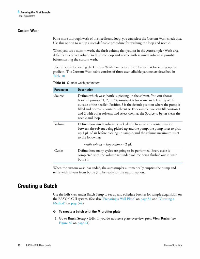
6 Running the First SampleCreating a Batch
60 EASY-nLC II User Guide Thermo Scientific
Custom Wash
For a more thorough wash of the needle and loop, you can select the Custom Wash check box. Use this option to set up a user-definable procedure for washing the loop and needle.
When you use a custom wash, the flush volume that you set in the Autosampler Wash area defaults to a preset volume to flush the loop and needle with as much solvent as possible before starting the custom wash.
The principle for setting the Custom Wash parameters is similar to that for setting up the gradient. The Custom Wash table consists of three user-editable parameters described in Table 10.
When the custom wash has ended, the autosampler automatically empties the pump and refills with solvent from bottle 3 to be ready for the next injection.
Creating a BatchUse the Edit view under Batch Setup to set up and schedule batches for sample acquisition on the EASY-nLC II system. (See also “Preparing a Well Plate” on page 54 and “Creating a Method” on page 54.)
To create a batch with the Microtiter plate
1. Go to Batch Setup > Edit. If you do not see a plate overview, press View Racks (see Figure 36 on page 61).
Table 10. Custom wash parameters
Parameter Description
Source Defines which wash bottle is picking up the solvent. You can choose between position 1, 2, or 3 (position 4 is for waste and cleaning of the outside of the needle). Position 3 is the default position where the pump is filled and normally contains solvent A. For example, you can fill position 1 and 2 with other solvents and select them as the Source to better clean the needle and loop.
Volume Defines how much solvent is picked up. To avoid any contamination between the solvent being picked up and the pump, the pump is set to pick up 1 μL of air before picking up sample, and the volume maximum is set to the following:
needle volume + loop volume – 2 μL
Cycles Defines how many cycles are going to be performed. Every cycle is completed with the volume set under volume being flushed out in wash bottle 4.
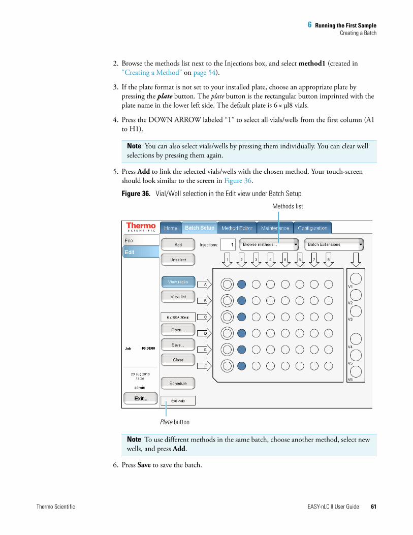
6 Running the First SampleCreating a Batch
Thermo Scientific EASY-nLC II User Guide 61
2. Browse the methods list next to the Injections box, and select method1 (created in “Creating a Method” on page 54).
3. If the plate format is not set to your installed plate, choose an appropriate plate by pressing the plate button. The plate button is the rectangular button imprinted with the plate name in the lower left side. The default plate is 6 × μl8 vials.
4. Press the DOWN ARROW labeled “1” to select all vials/wells from the first column (A1 to H1).
5. Press Add to link the selected vials/wells with the chosen method. Your touch-screen should look similar to the screen in Figure 36.
Figure 36. Vial/Well selection in the Edit view under Batch Setup
6. Press Save to save the batch.
Note You can also select vials/wells by pressing them individually. You can clear well selections by pressing them again.
Note To use different methods in the same batch, choose another method, select new wells, and press Add.
Plate button
Methods list

6 Running the First SampleCreating a Batch
62 EASY-nLC II User Guide Thermo Scientific
7. Press Schedule to submit the batch to the queue.
The application switches to the Home > Queue page (see Figure 37).
Figure 37. Queue page under the Home tab
8. If necessary, move any scheduled batches in the job queue by selecting it and pressing Up or Down. You can also delete batches from the Queue by selecting the batches and pressing Delete.
For a batch run to start automatically after the previous batch is finished, you must select its corresponding check box in the Auto-Continue column. In the case in Figure 37, the admin-20100824-1714 job does not auto-continue when the 6 x BSA 30min job is done.
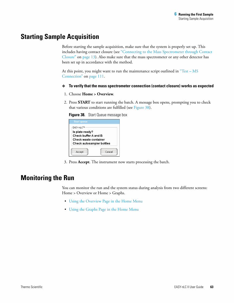
6 Running the First SampleStarting Sample Acquisition
Thermo Scientific EASY-nLC II User Guide 63
Starting Sample AcquisitionBefore starting the sample acquisition, make sure that the system is properly set up. This includes having contact closure (see “Connecting to the Mass Spectrometer through Contact Closure” on page 13). Also make sure that the mass spectrometer or any other detector has been set up in accordance with the method.
At this point, you might want to run the maintenance script outlined in “Test – MS Connection” on page 111.
To verify that the mass spectrometer connection (contact closure) works as expected
1. Choose Home > Overview.
2. Press START to start running the batch. A message box opens, prompting you to check that various conditions are fulfilled (see Figure 38).
Figure 38. Start Queue message box
3. Press Accept. The instrument now starts processing the batch.
Monitoring the RunYou can monitor the run and the system status during analysis from two different screens: Home > Overview or Home > Graphs.
• Using the Overview Page in the Home Menu
• Using the Graphs Page in the Home Menu
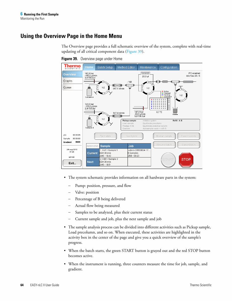
6 Running the First SampleMonitoring the Run
64 EASY-nLC II User Guide Thermo Scientific
Using the Overview Page in the Home Menu
The Overview page provides a full schematic overview of the system, complete with real-time updating of all critical component data (Figure 39).
Figure 39. Overview page under Home
• The system schematic provides information on all hardware parts in the system:
− Pump: position, pressure, and flow
− Valve: position
− Percentage of B being delivered
− Actual flow being measured
− Samples to be analyzed, plus their current status
− Current sample and job, plus the next sample and job
• The sample analysis process can be divided into different activities such as Pickup sample, Load precolumn, and so on. When executed, these activities are highlighted in the activity box in the center of the page and give you a quick overview of the sample’s progress.
• When the batch starts, the green START button is grayed out and the red STOP button becomes active.
• When the instrument is running, three counters measure the time for job, sample, and gradient.
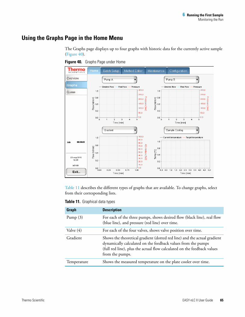
6 Running the First SampleMonitoring the Run
Thermo Scientific EASY-nLC II User Guide 65
Using the Graphs Page in the Home Menu
The Graphs page displays up to four graphs with historic data for the currently active sample (Figure 40).
Figure 40. Graphs Page under Home
Table 11 describes the different types of graphs that are available. To change graphs, select from their corresponding lists.
Table 11. Graphical data types
Graph Description
Pump (3) For each of the three pumps, shows desired flow (black line), real flow (blue line), and pressure (red line) over time.
Valve (4) For each of the four valves, shows valve position over time.
Gradient Shows the theoretical gradient (dotted red line) and the actual gradient dynamically calculated on the feedback values from the pumps (full red line), plus the actual flow calculated on the feedback values from the pumps.
Temperature Shows the measured temperature on the plate cooler over time.
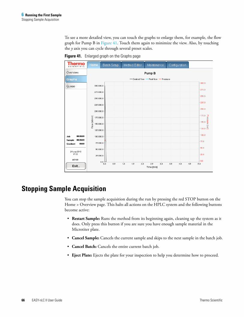
6 Running the First SampleStopping Sample Acquisition
66 EASY-nLC II User Guide Thermo Scientific
To see a more detailed view, you can touch the graphs to enlarge them, for example, the flow graph for Pump B in Figure 41. Touch them again to minimize the view. Also, by touching the y axis you can cycle through several preset scales.
Figure 41. Enlarged graph on the Graphs page
Stopping Sample AcquisitionYou can stop the sample acquisition during the run by pressing the red STOP button on the Home > Overview page. This halts all actions on the HPLC system and the following buttons become active:
• Restart Sample: Runs the method from its beginning again, cleaning up the system as it does. Only press this button if you are sure you have enough sample material in the Microtiter plate.
• Cancel Sample: Cancels the current sample and skips to the next sample in the batch job.
• Cancel Batch: Cancels the entire current batch job.
• Eject Plate: Ejects the plate for your inspection to help you determine how to proceed.
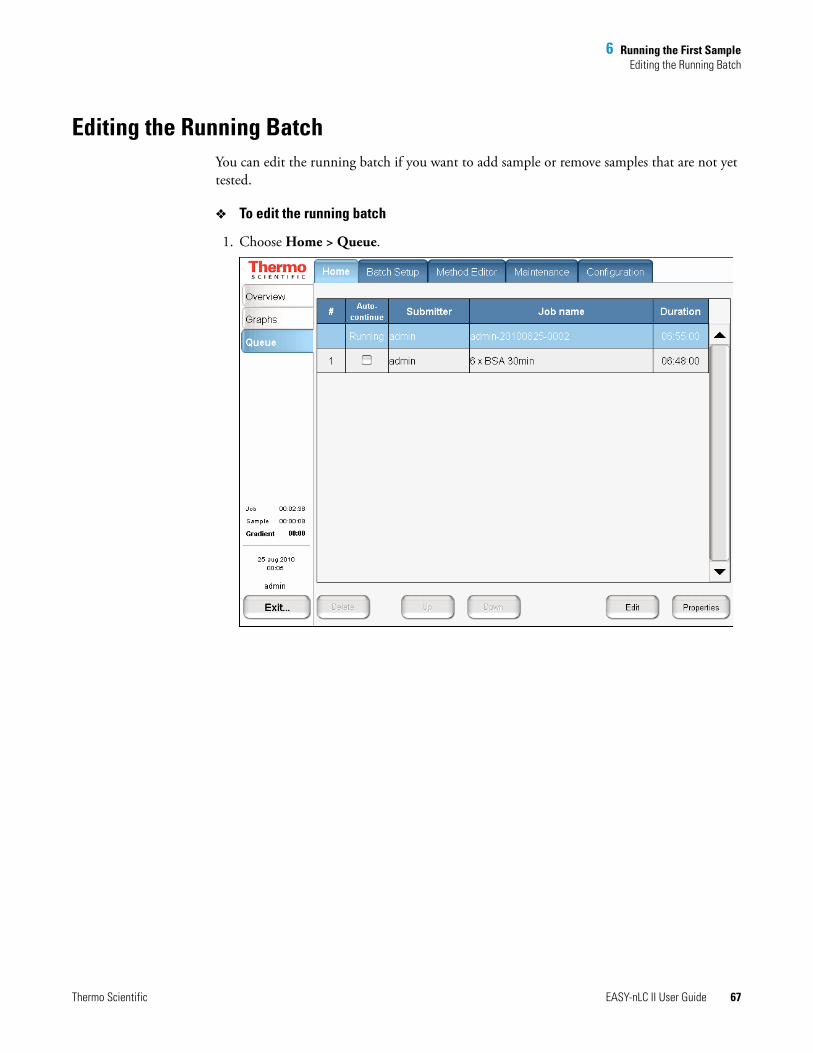
6 Running the First SampleEditing the Running Batch
Thermo Scientific EASY-nLC II User Guide 67
Editing the Running BatchYou can edit the running batch if you want to add sample or remove samples that are not yet tested.
To edit the running batch
1. Choose Home > Queue.
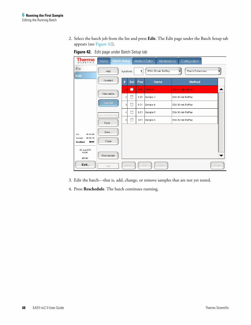
6 Running the First SampleEditing the Running Batch
68 EASY-nLC II User Guide Thermo Scientific
2. Select the batch job from the list and press Edit. The Edit page under the Batch Setup tab appears (see Figure 42).
Figure 42. Edit page under Batch Setup tab
3. Edit the batch—that is, add, change, or remove samples that are not yet tested.
4. Press Reschedule. The batch continues running.

6 Running the First SampleEditing the Running Batch
Thermo Scientific EASY-nLC II User Guide 69
5. (Optional) Go to Home > Queue (see Figure 43), check the sample list by pressing Properties, and then press Show Samples.
Figure 43. Sample list on the Queue page of the Home tab
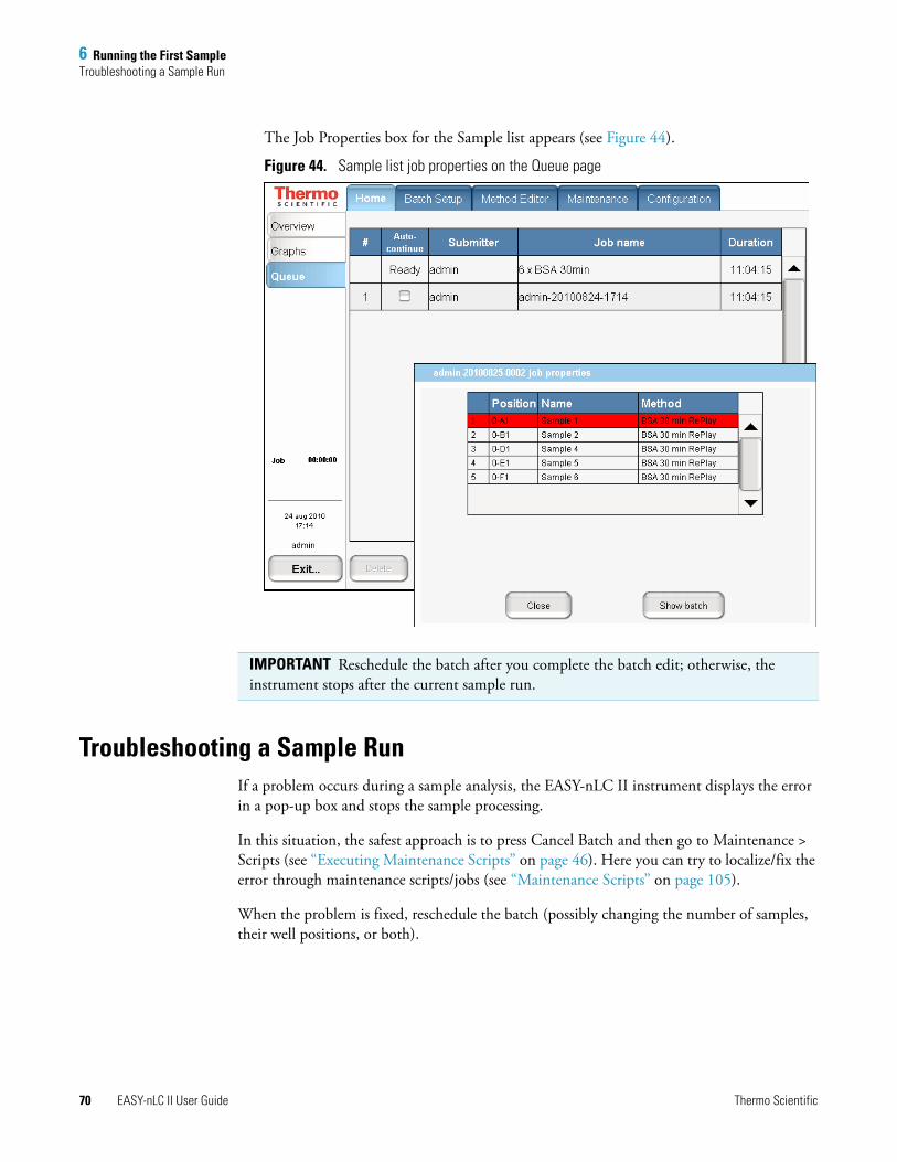
6 Running the First SampleTroubleshooting a Sample Run
70 EASY-nLC II User Guide Thermo Scientific
The Job Properties box for the Sample list appears (see Figure 44).
Figure 44. Sample list job properties on the Queue page
Troubleshooting a Sample RunIf a problem occurs during a sample analysis, the EASY-nLC II instrument displays the error in a pop-up box and stops the sample processing.
In this situation, the safest approach is to press Cancel Batch and then go to Maintenance > Scripts (see “Executing Maintenance Scripts” on page 46). Here you can try to localize/fix the error through maintenance scripts/jobs (see “Maintenance Scripts” on page 105).
When the problem is fixed, reschedule the batch (possibly changing the number of samples, their well positions, or both).
IMPORTANT Reschedule the batch after you complete the batch edit; otherwise, the instrument stops after the current sample run.
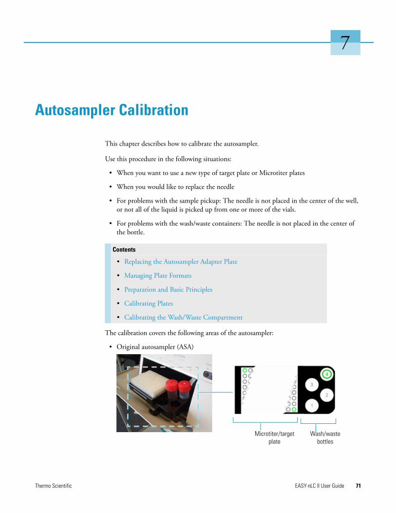
Thermo Scientific EASY-nLC II User Guide 71
7
Autosampler Calibration
This chapter describes how to calibrate the autosampler.
Use this procedure in the following situations:
• When you want to use a new type of target plate or Microtiter plates
• When you would like to replace the needle
• For problems with the sample pickup: The needle is not placed in the center of the well, or not all of the liquid is picked up from one or more of the vials.
• For problems with the wash/waste containers: The needle is not placed in the center of the bottle.
The calibration covers the following areas of the autosampler:
• Original autosampler (ASA)
Contents
• Replacing the Autosampler Adapter Plate
• Managing Plate Formats
• Preparation and Basic Principles
• Calibrating Plates
• Calibrating the Wash/Waste Compartment
Microtiter/targetplate
Wash/wastebottles
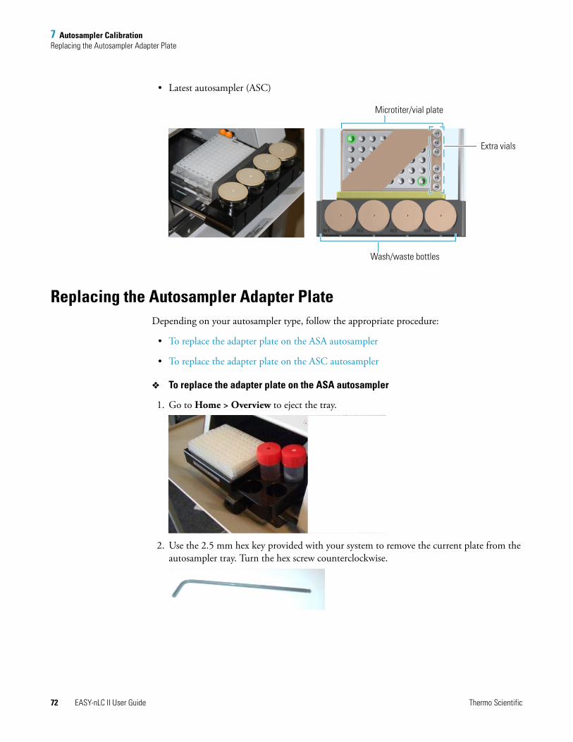
7 Autosampler CalibrationReplacing the Autosampler Adapter Plate
72 EASY-nLC II User Guide Thermo Scientific
• Latest autosampler (ASC)
Replacing the Autosampler Adapter PlateDepending on your autosampler type, follow the appropriate procedure:
• To replace the adapter plate on the ASA autosampler
• To replace the adapter plate on the ASC autosampler
To replace the adapter plate on the ASA autosampler
1. Go to Home > Overview to eject the tray.
2. Use the 2.5 mm hex key provided with your system to remove the current plate from the autosampler tray. Turn the hex screw counterclockwise.
Microtiter/vial plate
Wash/waste bottles
Extra vials
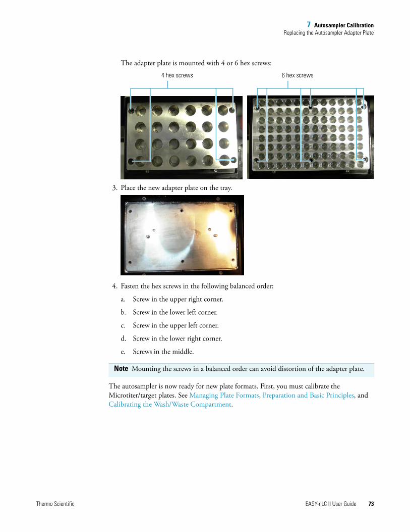
7 Autosampler CalibrationReplacing the Autosampler Adapter Plate
Thermo Scientific EASY-nLC II User Guide 73
The adapter plate is mounted with 4 or 6 hex screws:
3. Place the new adapter plate on the tray.
4. Fasten the hex screws in the following balanced order:
a. Screw in the upper right corner.
b. Screw in the lower left corner.
c. Screw in the upper left corner.
d. Screw in the lower right corner.
e. Screws in the middle.
The autosampler is now ready for new plate formats. First, you must calibrate the Microtiter/target plates. See Managing Plate Formats, Preparation and Basic Principles, and Calibrating the Wash/Waste Compartment.
Note Mounting the screws in a balanced order can avoid distortion of the adapter plate.
4 hex screws 6 hex screws
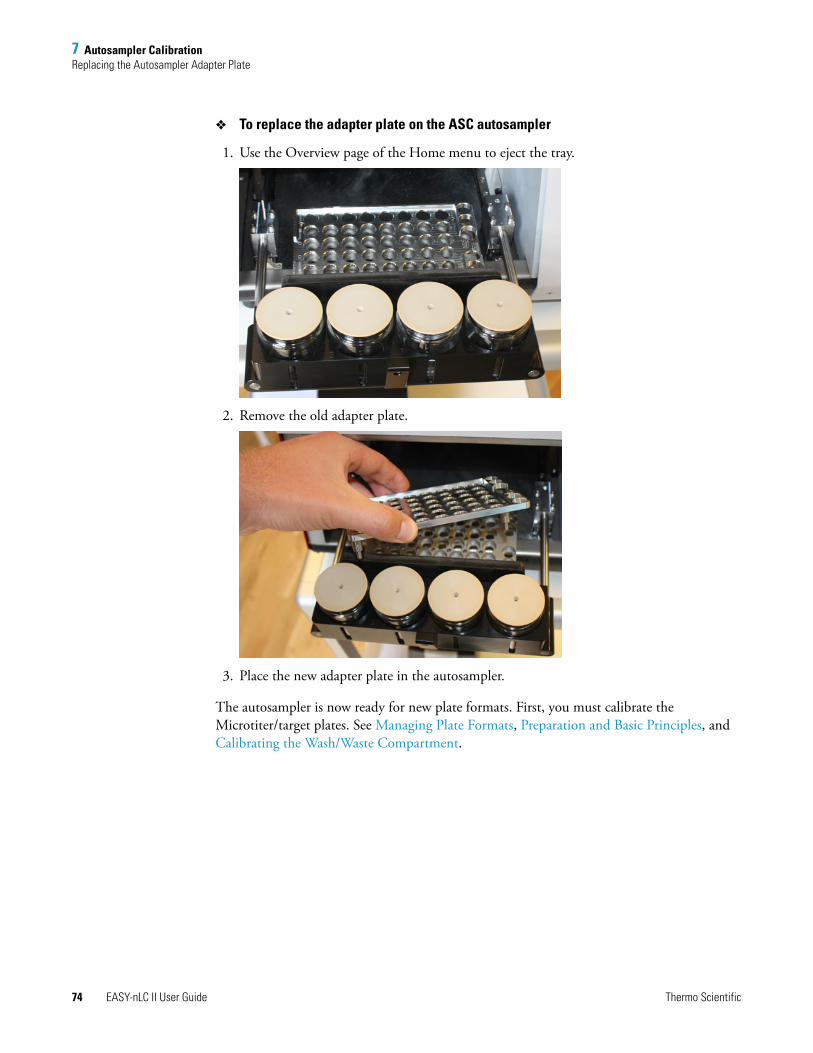
7 Autosampler CalibrationReplacing the Autosampler Adapter Plate
74 EASY-nLC II User Guide Thermo Scientific
To replace the adapter plate on the ASC autosampler
1. Use the Overview page of the Home menu to eject the tray.
2. Remove the old adapter plate.
3. Place the new adapter plate in the autosampler.
The autosampler is now ready for new plate formats. First, you must calibrate the Microtiter/target plates. See Managing Plate Formats, Preparation and Basic Principles, and Calibrating the Wash/Waste Compartment.
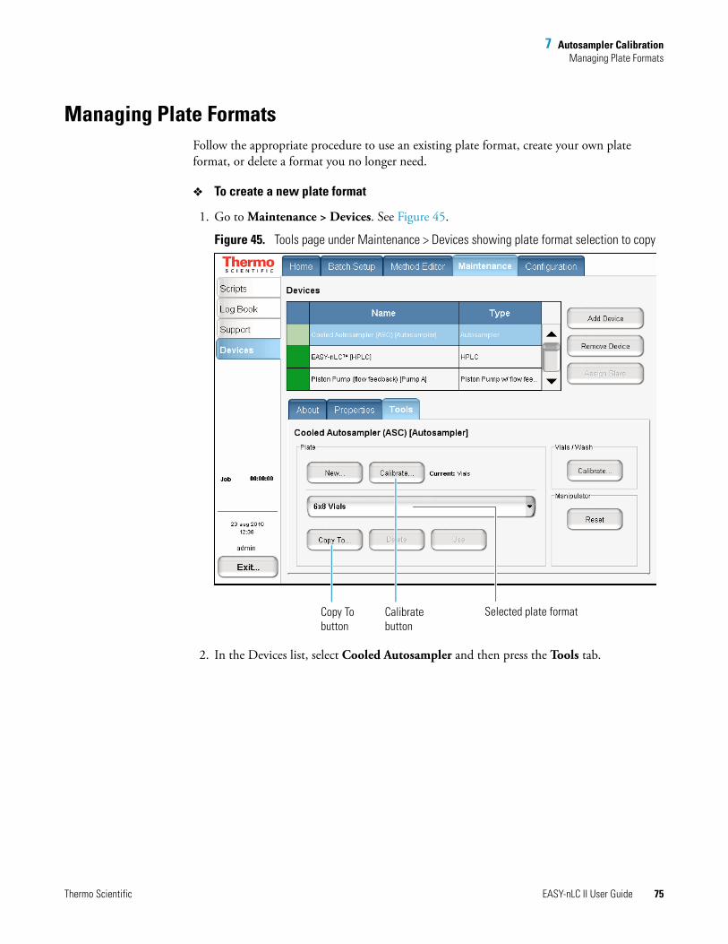
7 Autosampler CalibrationManaging Plate Formats
Thermo Scientific EASY-nLC II User Guide 75
Managing Plate FormatsFollow the appropriate procedure to use an existing plate format, create your own plate format, or delete a format you no longer need.
To create a new plate format
1. Go to Maintenance > Devices. See Figure 45.
Figure 45. Tools page under Maintenance > Devices showing plate format selection to copy
2. In the Devices list, select Cooled Autosampler and then press the Tools tab.
Calibrate button
Copy To button
Selected plate format
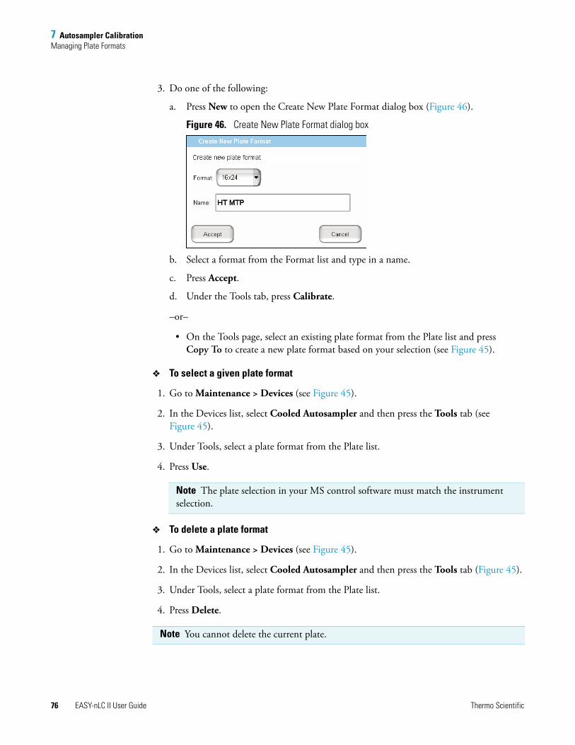
7 Autosampler CalibrationManaging Plate Formats
76 EASY-nLC II User Guide Thermo Scientific
3. Do one of the following:
a. Press New to open the Create New Plate Format dialog box (Figure 46).
Figure 46. Create New Plate Format dialog box
b. Select a format from the Format list and type in a name.
c. Press Accept.
d. Under the Tools tab, press Calibrate.
–or–
• On the Tools page, select an existing plate format from the Plate list and press Copy To to create a new plate format based on your selection (see Figure 45).
To select a given plate format
1. Go to Maintenance > Devices (see Figure 45).
2. In the Devices list, select Cooled Autosampler and then press the Tools tab (see Figure 45).
3. Under Tools, select a plate format from the Plate list.
4. Press Use.
To delete a plate format
1. Go to Maintenance > Devices (see Figure 45).
2. In the Devices list, select Cooled Autosampler and then press the Tools tab (Figure 45).
3. Under Tools, select a plate format from the Plate list.
4. Press Delete.
Note The plate selection in your MS control software must match the instrument selection.
Note You cannot delete the current plate.
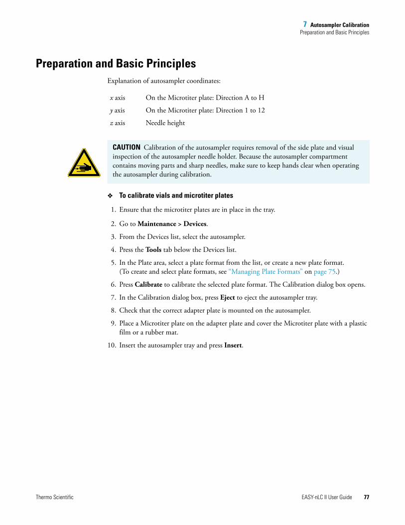
7 Autosampler CalibrationPreparation and Basic Principles
Thermo Scientific EASY-nLC II User Guide 77
Preparation and Basic PrinciplesExplanation of autosampler coordinates:
To calibrate vials and microtiter plates
1. Ensure that the microtiter plates are in place in the tray.
2. Go to Maintenance > Devices.
3. From the Devices list, select the autosampler.
4. Press the Tools tab below the Devices list.
5. In the Plate area, select a plate format from the list, or create a new plate format. (To create and select plate formats, see “Managing Plate Formats” on page 75.)
6. Press Calibrate to calibrate the selected plate format. The Calibration dialog box opens.
7. In the Calibration dialog box, press Eject to eject the autosampler tray.
8. Check that the correct adapter plate is mounted on the autosampler.
9. Place a Microtiter plate on the adapter plate and cover the Microtiter plate with a plastic film or a rubber mat.
10. Insert the autosampler tray and press Insert.
x axis On the Microtiter plate: Direction A to H
y axis On the Microtiter plate: Direction 1 to 12
z axis Needle height
CAUTION Calibration of the autosampler requires removal of the side plate and visual inspection of the autosampler needle holder. Because the autosampler compartment contains moving parts and sharp needles, make sure to keep hands clear when operating the autosampler during calibration.
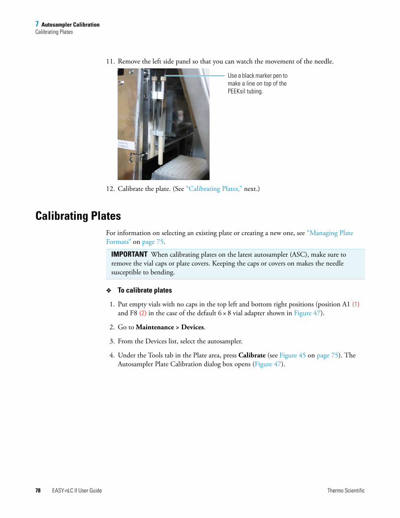
7 Autosampler CalibrationCalibrating Plates
78 EASY-nLC II User Guide Thermo Scientific
11. Remove the left side panel so that you can watch the movement of the needle.
12. Calibrate the plate. (See “Calibrating Plates,” next.)
Calibrating PlatesFor information on selecting an existing plate or creating a new one, see “Managing Plate Formats” on page 75.
To calibrate plates
1. Put empty vials with no caps in the top left and bottom right positions (position A1 (1) and F8 (2) in the case of the default 6 × 8 vial adapter shown in Figure 47).
2. Go to Maintenance > Devices.
3. From the Devices list, select the autosampler.
4. Under the Tools tab in the Plate area, press Calibrate (see Figure 45 on page 75). The Autosampler Plate Calibration dialog box opens (Figure 47).
Use a black marker pen to make a line on top of the PEEKsil tubing.
IMPORTANT When calibrating plates on the latest autosampler (ASC), make sure to remove the vial caps or plate covers. Keeping the caps or covers on makes the needle susceptible to bending.
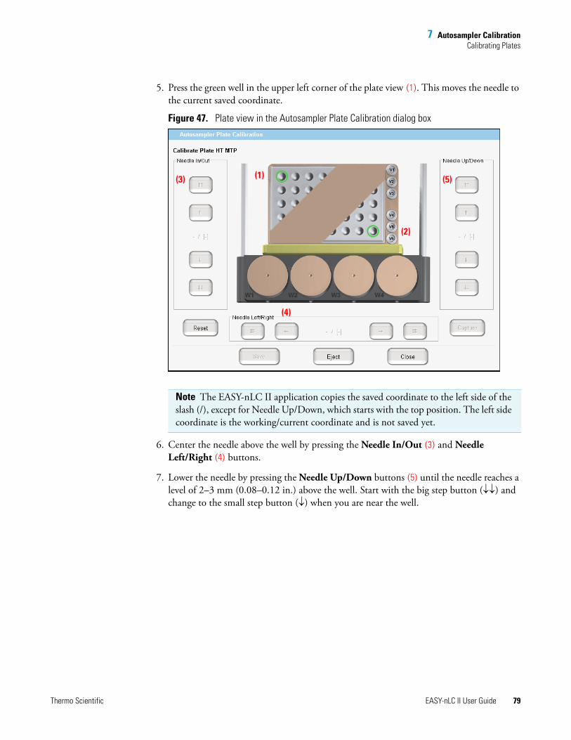
7 Autosampler CalibrationCalibrating Plates
Thermo Scientific EASY-nLC II User Guide 79
5. Press the green well in the upper left corner of the plate view (1). This moves the needle to the current saved coordinate.
Figure 47. Plate view in the Autosampler Plate Calibration dialog box
6. Center the needle above the well by pressing the Needle In/Out (3) and Needle Left/Right (4) buttons.
7. Lower the needle by pressing the Needle Up/Down buttons (5) until the needle reaches a level of 2–3 mm (0.08–0.12 in.) above the well. Start with the big step button (↓↓) and change to the small step button (↓) when you are near the well.
Note The EASY-nLC II application copies the saved coordinate to the left side of the slash (/), except for Needle Up/Down, which starts with the top position. The left side coordinate is the working/current coordinate and is not saved yet.
(1) (5)(3)
(2)
(4)
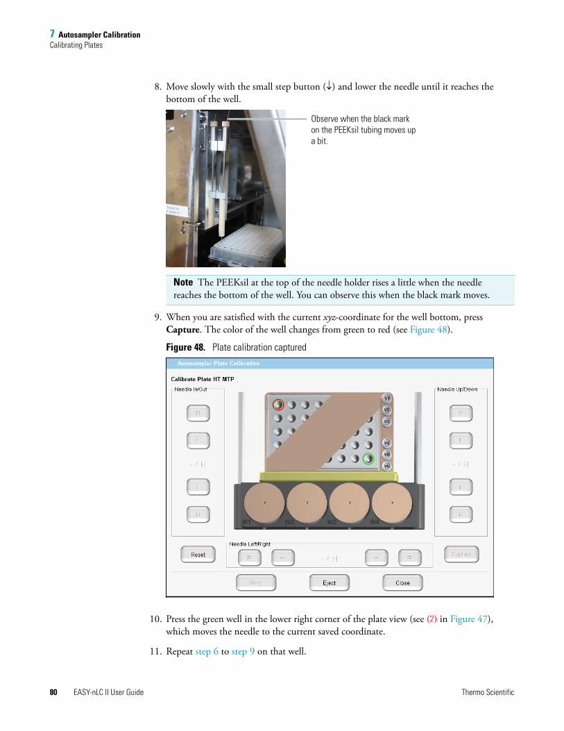
7 Autosampler CalibrationCalibrating Plates
80 EASY-nLC II User Guide Thermo Scientific
8. Move slowly with the small step button (↓) and lower the needle until it reaches the bottom of the well.
9. When you are satisfied with the current xyz-coordinate for the well bottom, press Capture. The color of the well changes from green to red (see Figure 48).
Figure 48. Plate calibration captured
10. Press the green well in the lower right corner of the plate view (see (2) in Figure 47), which moves the needle to the current saved coordinate.
11. Repeat step 6 to step 9 on that well.
Note The PEEKsil at the top of the needle holder rises a little when the needle reaches the bottom of the well. You can observe this when the black mark moves.
Observe when the black mark on the PEEKsil tubing moves up a bit.
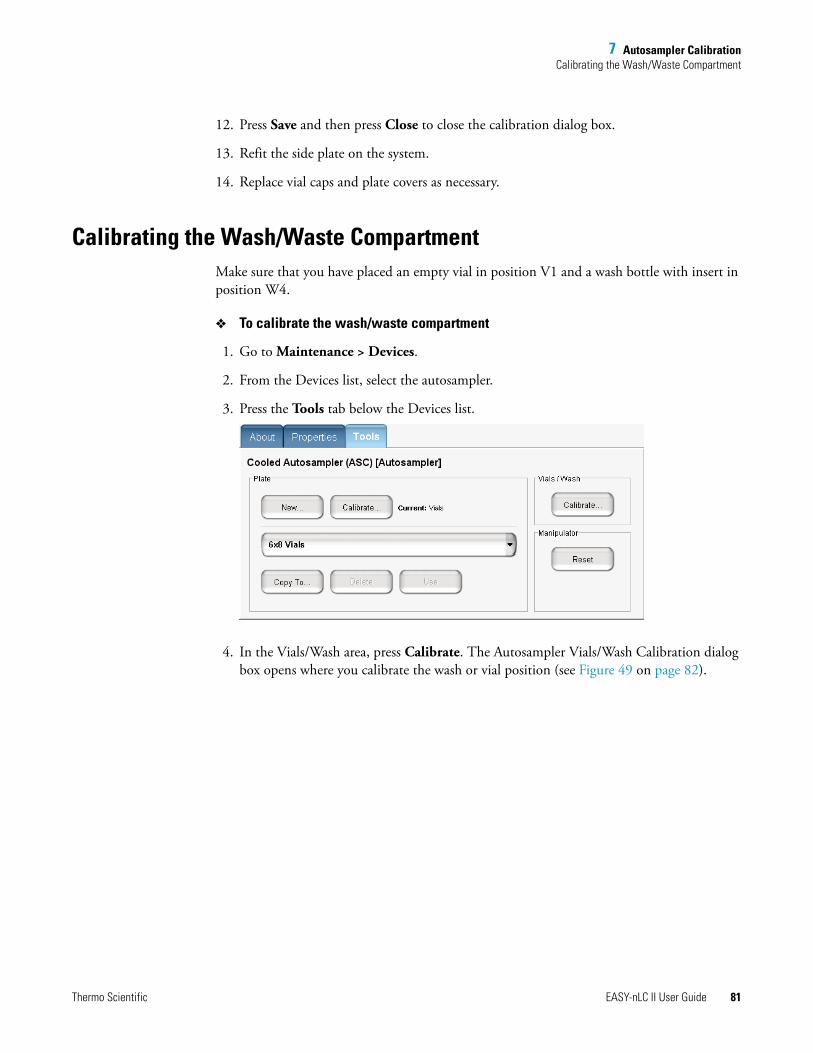
7 Autosampler CalibrationCalibrating the Wash/Waste Compartment
Thermo Scientific EASY-nLC II User Guide 81
12. Press Save and then press Close to close the calibration dialog box.
13. Refit the side plate on the system.
14. Replace vial caps and plate covers as necessary.
Calibrating the Wash/Waste CompartmentMake sure that you have placed an empty vial in position V1 and a wash bottle with insert in position W4.
To calibrate the wash/waste compartment
1. Go to Maintenance > Devices.
2. From the Devices list, select the autosampler.
3. Press the Tools tab below the Devices list.
4. In the Vials/Wash area, press Calibrate. The Autosampler Vials/Wash Calibration dialog box opens where you calibrate the wash or vial position (see Figure 49 on page 82).
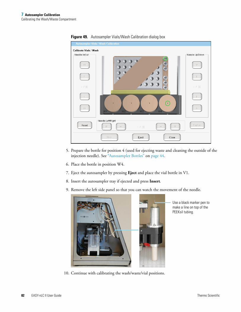
7 Autosampler CalibrationCalibrating the Wash/Waste Compartment
82 EASY-nLC II User Guide Thermo Scientific
Figure 49. Autosampler Vials/Wash Calibration dialog box
5. Prepare the bottle for position 4 (used for ejecting waste and cleaning the outside of the injection needle). See “Autosampler Bottles” on page 44.
6. Place the bottle in position W4.
7. Eject the autosampler by pressing Eject and place the vial bottle in V1.
8. Insert the autosampler tray if ejected and press Insert.
9. Remove the left side panel so that you can watch the movement of the needle.
10. Continue with calibrating the wash/waste/vial positions.
Use a black marker pen to make a line on top of the PEEKsil tubing.
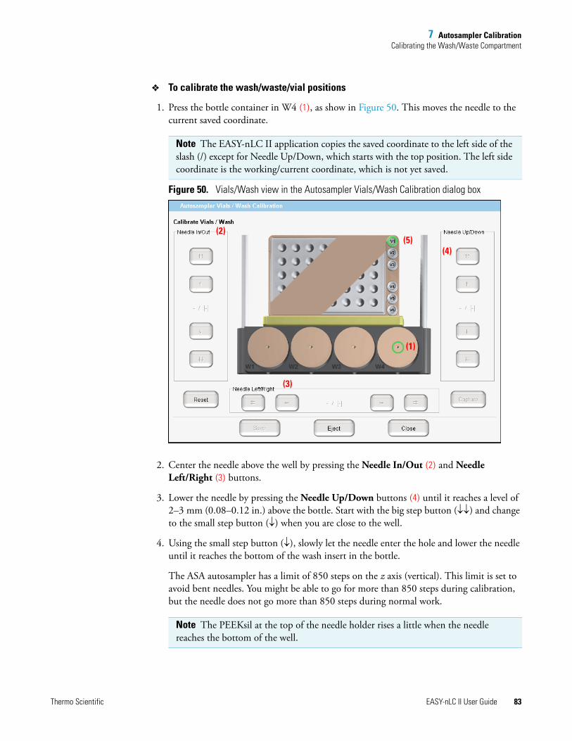
7 Autosampler CalibrationCalibrating the Wash/Waste Compartment
Thermo Scientific EASY-nLC II User Guide 83
To calibrate the wash/waste/vial positions
1. Press the bottle container in W4 (1), as show in Figure 50. This moves the needle to the current saved coordinate.
Figure 50. Vials/Wash view in the Autosampler Vials/Wash Calibration dialog box
2. Center the needle above the well by pressing the Needle In/Out (2) and Needle Left/Right (3) buttons.
3. Lower the needle by pressing the Needle Up/Down buttons (4) until it reaches a level of 2–3 mm (0.08–0.12 in.) above the bottle. Start with the big step button (↓↓) and change to the small step button (↓) when you are close to the well.
4. Using the small step button (↓), slowly let the needle enter the hole and lower the needle until it reaches the bottom of the wash insert in the bottle.
The ASA autosampler has a limit of 850 steps on the z axis (vertical). This limit is set to avoid bent needles. You might be able to go for more than 850 steps during calibration, but the needle does not go more than 850 steps during normal work.
Note The EASY-nLC II application copies the saved coordinate to the left side of the slash (/) except for Needle Up/Down, which starts with the top position. The left side coordinate is the working/current coordinate, which is not yet saved.
Note The PEEKsil at the top of the needle holder rises a little when the needle reaches the bottom of the well.
(1)
(4)(5)
(2)
(3)
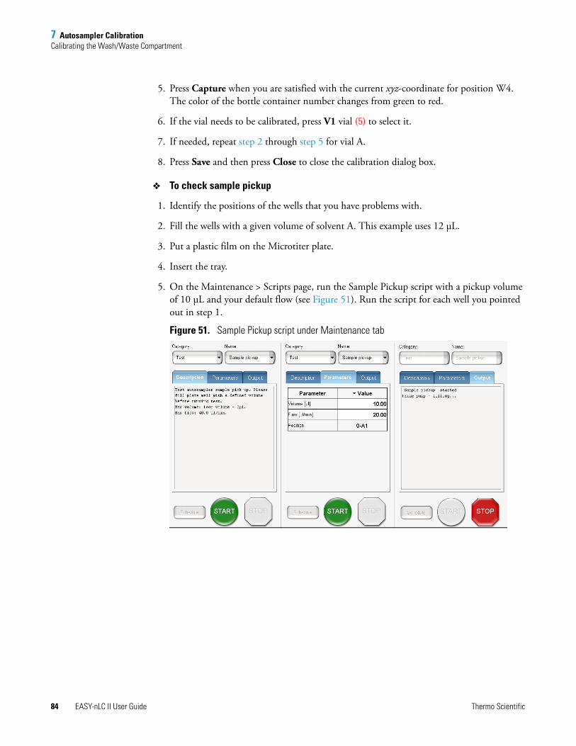
7 Autosampler CalibrationCalibrating the Wash/Waste Compartment
84 EASY-nLC II User Guide Thermo Scientific
5. Press Capture when you are satisfied with the current xyz-coordinate for position W4. The color of the bottle container number changes from green to red.
6. If the vial needs to be calibrated, press V1 vial (5) to select it.
7. If needed, repeat step 2 through step 5 for vial A.
8. Press Save and then press Close to close the calibration dialog box.
To check sample pickup
1. Identify the positions of the wells that you have problems with.
2. Fill the wells with a given volume of solvent A. This example uses 12 μL.
3. Put a plastic film on the Microtiter plate.
4. Insert the tray.
5. On the Maintenance > Scripts page, run the Sample Pickup script with a pickup volume of 10 μL and your default flow (see Figure 51). Run the script for each well you pointed out in step 1.
Figure 51. Sample Pickup script under Maintenance tab
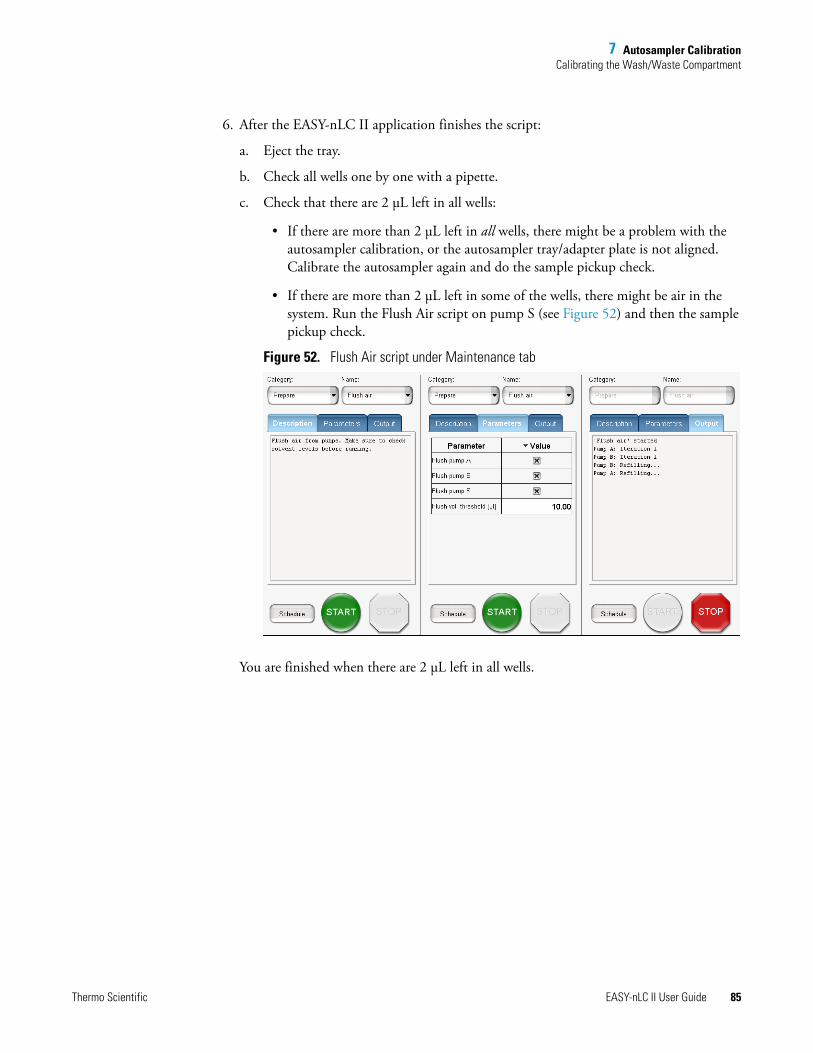
7 Autosampler CalibrationCalibrating the Wash/Waste Compartment
Thermo Scientific EASY-nLC II User Guide 85
6. After the EASY-nLC II application finishes the script:
a. Eject the tray.
b. Check all wells one by one with a pipette.
c. Check that there are 2 μL left in all wells:
• If there are more than 2 μL left in all wells, there might be a problem with the autosampler calibration, or the autosampler tray/adapter plate is not aligned. Calibrate the autosampler again and do the sample pickup check.
• If there are more than 2 μL left in some of the wells, there might be air in the system. Run the Flush Air script on pump S (see Figure 52) and then the sample pickup check.
Figure 52. Flush Air script under Maintenance tab
You are finished when there are 2 μL left in all wells.

Thermo Scientific EASY-nLC II User Guide 87
8
Troubleshooting
This chapter offers help with the EASY-nLC II system in the form of troubleshooting tips. The following tables provide troubleshooting tips in several different areas.
Contents
• Running a Batch
• Autosampler
• Contact Closure
• Network Access
• Starting Up the System
• System Component States (Valves, Pumps, Autosampler, and Plate Cooler)
• Miscellaneous
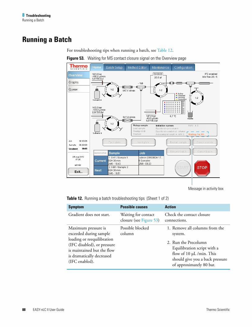
8 TroubleshootingRunning a Batch
88 EASY-nLC II User Guide Thermo Scientific
Running a BatchFor troubleshooting tips when running a batch, see Table 12.
Figure 53. Waiting for MS contact closure signal on the Overview page
Table 12. Running a batch troubleshooting tips (Sheet 1 of 2)
Symptom Possible causes Action
Gradient does not start. Waiting for contact closure (see Figure 53)
Check the contact closure connections.
Maximum pressure is exceeded during sample loading or reequilibration (IFC disabled), or pressure is maintained but the flow is dramatically decreased (IFC enabled).
Possible blocked column
1. Remove all columns from the system.
2. Run the Precolumn Equilibration script with a flow of 10 μL /min. This should give you a back pressure of approximately 80 bar.
Message in activity box
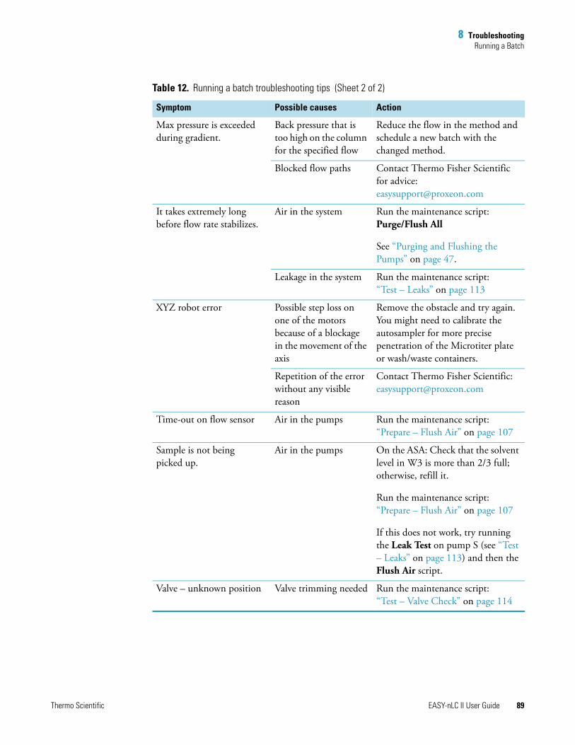
8 TroubleshootingRunning a Batch
Thermo Scientific EASY-nLC II User Guide 89
Max pressure is exceeded during gradient.
Back pressure that is too high on the column for the specified flow
Reduce the flow in the method and schedule a new batch with the changed method.
Blocked flow paths Contact Thermo Fisher Scientific for advice: [email protected]
It takes extremely long before flow rate stabilizes.
Air in the system Run the maintenance script: Purge/Flush All
See “Purging and Flushing the Pumps” on page 47.
Leakage in the system Run the maintenance script: “Test – Leaks” on page 113
XYZ robot error Possible step loss on one of the motors because of a blockage in the movement of the axis
Remove the obstacle and try again. You might need to calibrate the autosampler for more precise penetration of the Microtiter plate or wash/waste containers.
Repetition of the error without any visible reason
Contact Thermo Fisher Scientific: [email protected]
Time-out on flow sensor Air in the pumps Run the maintenance script:“Prepare – Flush Air” on page 107
Sample is not being picked up.
Air in the pumps On the ASA: Check that the solvent level in W3 is more than 2/3 full; otherwise, refill it.
Run the maintenance script: “Prepare – Flush Air” on page 107
If this does not work, try running the Leak Test on pump S (see “Test – Leaks” on page 113) and then the Flush Air script.
Valve – unknown position Valve trimming needed Run the maintenance script:“Test – Valve Check” on page 114
Table 12. Running a batch troubleshooting tips (Sheet 2 of 2)
Symptom Possible causes Action

8 TroubleshootingAutosampler
90 EASY-nLC II User Guide Thermo Scientific
AutosamplerSee Table 13 for tips on handling autosampler issues. To access the Autosampler control window (Figure 54), go to Home > Overview, and press the plate icon.
Figure 54. Autosampler control window
Table 13. Autosampler troubleshooting tips (Sheet 1 of 2)
Symptom Possible causes Action
Sample pickup fails. Bad autosampler calibration or air in the sample (S) pump
1. Fill some of the wells with a given volume of solvent A, for example, 12 μL.
2. Put a plastic film on the Microtiter plate.
3. Run the maintenance script: “Test – Sample Pickup” on page 112, with a pickup volume of 10 μL and your default flow. Run the script for each well.
4. Eject the tray and check the wells one by one with a pipette.
5. Run the “Prepare – Flush Air” on page 107 script, or calibrate the autosampler if the problem still appears.
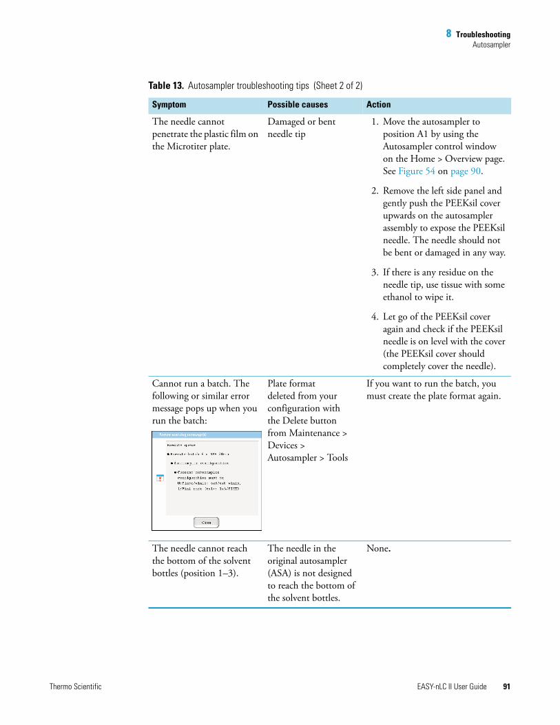
8 TroubleshootingAutosampler
Thermo Scientific EASY-nLC II User Guide 91
The needle cannot penetrate the plastic film on the Microtiter plate.
Damaged or bent needle tip
1. Move the autosampler to position A1 by using the Autosampler control window on the Home > Overview page. See Figure 54 on page 90.
2. Remove the left side panel and gently push the PEEKsil cover upwards on the autosampler assembly to expose the PEEKsil needle. The needle should not be bent or damaged in any way.
3. If there is any residue on the needle tip, use tissue with some ethanol to wipe it.
4. Let go of the PEEKsil cover again and check if the PEEKsil needle is on level with the cover (the PEEKsil cover should completely cover the needle).
Cannot run a batch. The following or similar error message pops up when you run the batch:
Plate format deleted from your configuration with the Delete button from Maintenance > Devices > Autosampler > Tools
If you want to run the batch, you must create the plate format again.
The needle cannot reach the bottom of the solvent bottles (position 1–3).
The needle in the original autosampler (ASA) is not designed to reach the bottom of the solvent bottles.
None.
Table 13. Autosampler troubleshooting tips (Sheet 2 of 2)
Symptom Possible causes Action
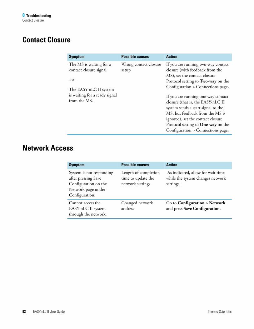
8 TroubleshootingContact Closure
92 EASY-nLC II User Guide Thermo Scientific
Contact Closure
Network Access
Symptom Possible causes Action
The MS is waiting for a contact closure signal.
-or-
The EASY-nLC II system is waiting for a ready signal from the MS.
Wrong contact closure setup
If you are running two-way contact closure (with feedback from the MS), set the contact closure Protocol setting to Two-way on the Configuration > Connections page.
If you are running one-way contact closure (that is, the EASY-nLC II system sends a start signal to the MS, but feedback from the MS is ignored), set the contact closure Protocol setting to One-way on the Configuration > Connections page.
Symptom Possible causes Action
System is not responding after pressing Save Configuration on the Network page under Configuration.
Length of completion time to update the network settings
As indicated, allow for wait time while the system changes network settings.
Cannot access the EASY-nLC II system through the network.
Changed network address
Go to Configuration > Network and press Save Configuration.
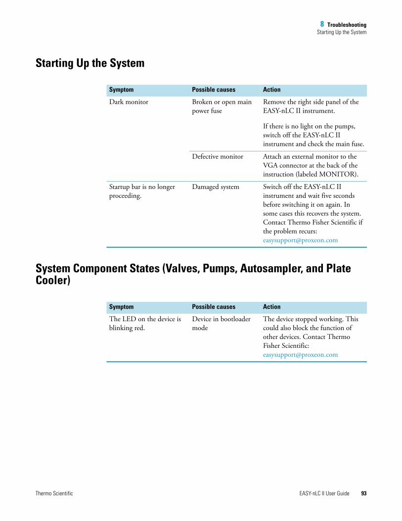
8 TroubleshootingStarting Up the System
Thermo Scientific EASY-nLC II User Guide 93
Starting Up the System
System Component States (Valves, Pumps, Autosampler, and Plate Cooler)
Symptom Possible causes Action
Dark monitor Broken or open main power fuse
Remove the right side panel of the EASY-nLC II instrument.
If there is no light on the pumps, switch off the EASY-nLC II instrument and check the main fuse.
Defective monitor Attach an external monitor to the VGA connector at the back of the instruction (labeled MONITOR).
Startup bar is no longer proceeding.
Damaged system Switch off the EASY-nLC II instrument and wait five seconds before switching it on again. In some cases this recovers the system. Contact Thermo Fisher Scientific if the problem recurs: [email protected]
Symptom Possible causes Action
The LED on the device is blinking red.
Device in bootloader mode
The device stopped working. This could also block the function of other devices. Contact Thermo Fisher Scientific: [email protected]
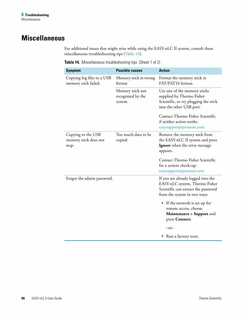
8 TroubleshootingMiscellaneous
94 EASY-nLC II User Guide Thermo Scientific
MiscellaneousFor additional issues that might arise while using the EASY-nLC II system, consult these miscellaneous troubleshooting tips (Table 14).
Table 14. Miscellaneous troubleshooting tips (Sheet 1 of 2)
Symptom Possible causes Action
Copying log files to a USB memory stick failed.
Memory stick in wrong format
Format the memory stick in FAT/FAT16 format.
Memory stick not recognized by the system
Use one of the memory sticks supplied by Thermo Fisher Scientific, or try plugging the stick into the other USB port.
Contact Thermo Fisher Scientific if neither action works: [email protected]
Copying to the USB memory stick does not stop.
Too much data to be copied
Remove the memory stick from the EASY-nLC II system and press Ignore when the error message appears.
Contact Thermo Fisher Scientific for a system check-up: [email protected]
Forgot the admin password. If you are already logged into the EASY-nLC system, Thermo Fisher Scientific can extract the password from the system in two ways:
• If the network is set up for remote access, choose Maintenance > Support and press Connect.
–or–
• Run a factory reset.
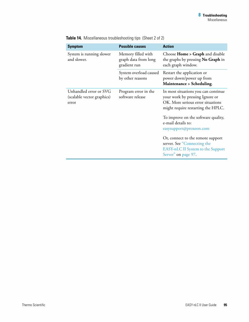
8 TroubleshootingMiscellaneous
Thermo Scientific EASY-nLC II User Guide 95
System is running slower and slower.
Memory filled with graph data from long gradient run
Choose Home > Graph and disable the graphs by pressing No Graph in each graph window.
System overload caused by other reasons
Restart the application or power down/power up from Maintenance > Scheduling.
Unhandled error or SVG (scalable vector graphics) error
Program error in the software release
In most situations you can continue your work by pressing Ignore or OK. More serious error situations might require restarting the HPLC.
To improve on the software quality, e-mail details to:[email protected]
Or, connect to the remote support server. See “Connecting the EASY-nLC II System to the Support Server” on page 97.
Table 14. Miscellaneous troubleshooting tips (Sheet 2 of 2)
Symptom Possible causes Action

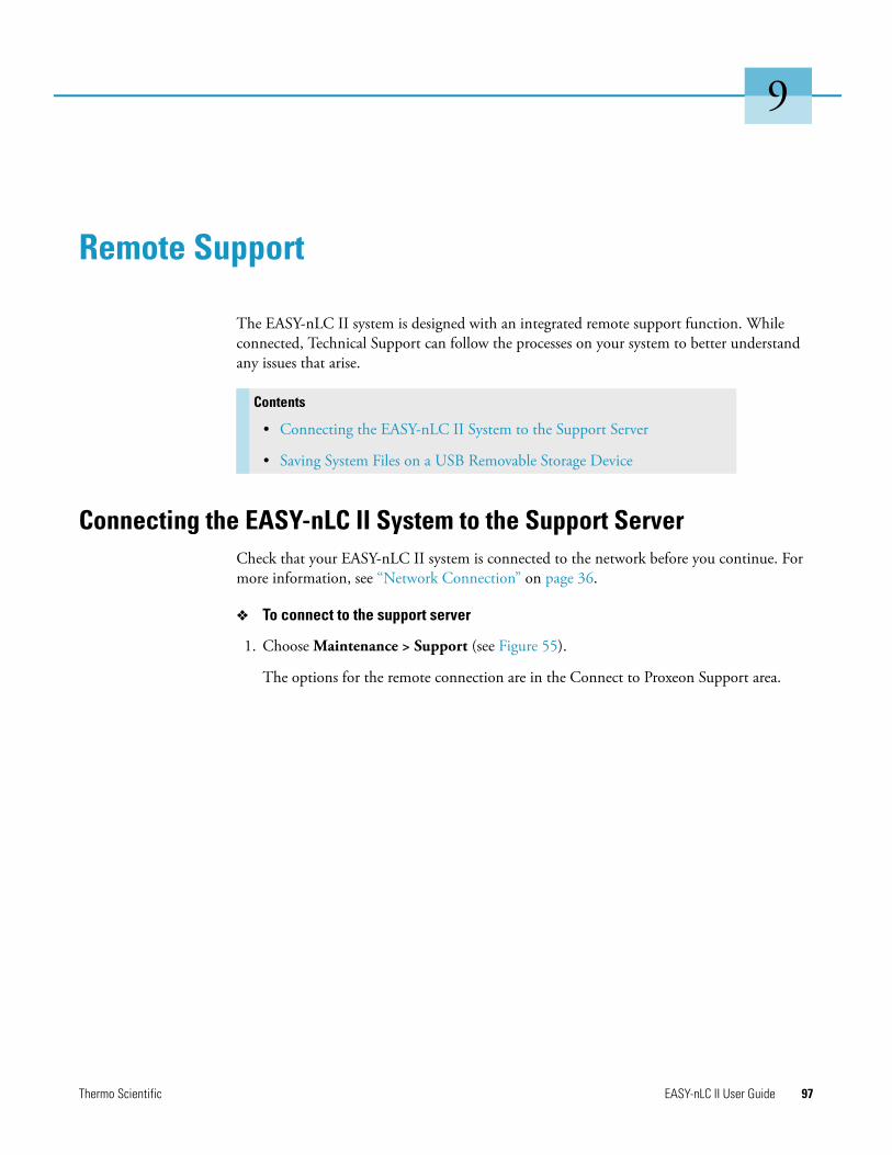
Thermo Scientific EASY-nLC II User Guide 97
9
Remote Support
The EASY-nLC II system is designed with an integrated remote support function. While connected, Technical Support can follow the processes on your system to better understand any issues that arise.
Connecting the EASY-nLC II System to the Support ServerCheck that your EASY-nLC II system is connected to the network before you continue. For more information, see “Network Connection” on page 36.
To connect to the support server
1. Choose Maintenance > Support (see Figure 55).
The options for the remote connection are in the Connect to Proxeon Support area.
Contents
• Connecting the EASY-nLC II System to the Support Server
• Saving System Files on a USB Removable Storage Device
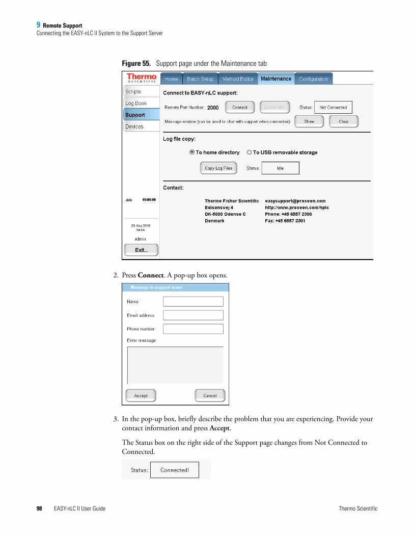
9 Remote SupportConnecting the EASY-nLC II System to the Support Server
98 EASY-nLC II User Guide Thermo Scientific
Figure 55. Support page under the Maintenance tab
2. Press Connect. A pop-up box opens.
3. In the pop-up box, briefly describe the problem that you are experiencing. Provide your contact information and press Accept.
The Status box on the right side of the Support page changes from Not Connected to Connected.
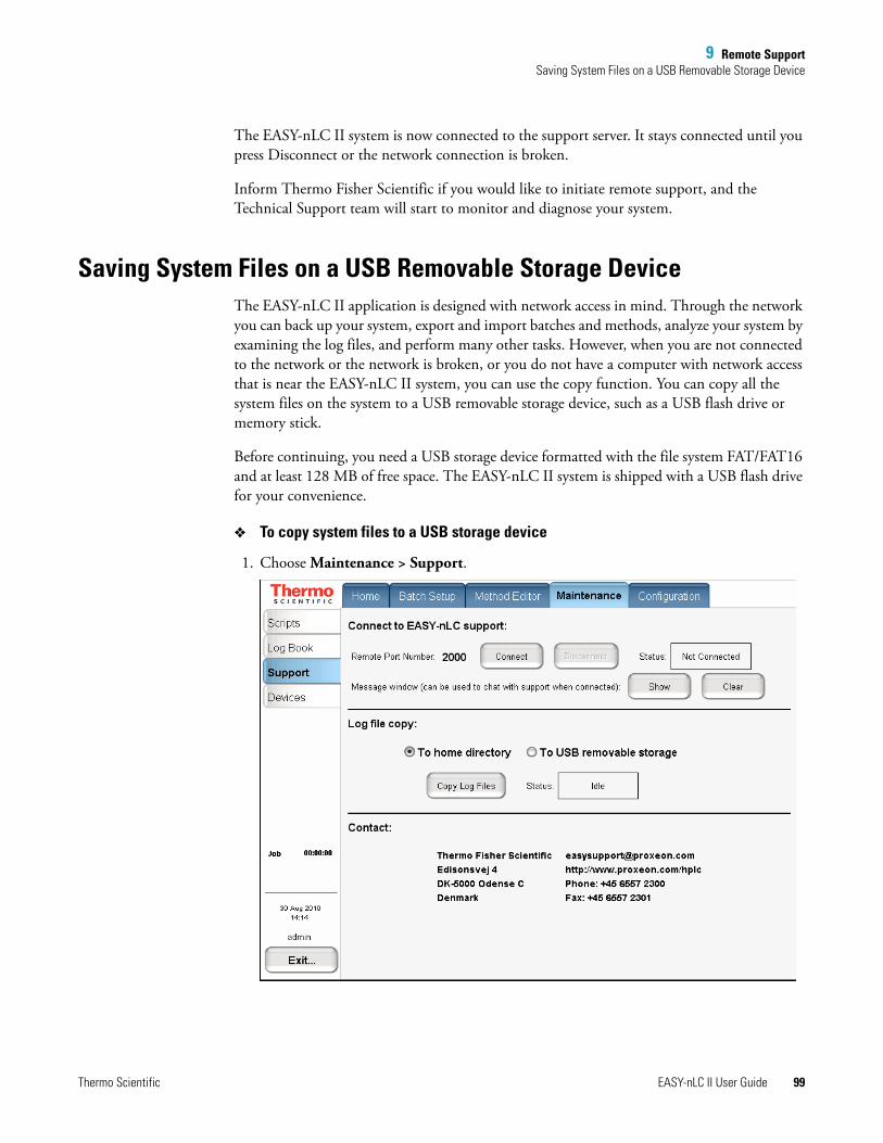
9 Remote SupportSaving System Files on a USB Removable Storage Device
Thermo Scientific EASY-nLC II User Guide 99
The EASY-nLC II system is now connected to the support server. It stays connected until you press Disconnect or the network connection is broken.
Inform Thermo Fisher Scientific if you would like to initiate remote support, and the Technical Support team will start to monitor and diagnose your system.
Saving System Files on a USB Removable Storage DeviceThe EASY-nLC II application is designed with network access in mind. Through the network you can back up your system, export and import batches and methods, analyze your system by examining the log files, and perform many other tasks. However, when you are not connected to the network or the network is broken, or you do not have a computer with network access that is near the EASY-nLC II system, you can use the copy function. You can copy all the system files on the system to a USB removable storage device, such as a USB flash drive or memory stick.
Before continuing, you need a USB storage device formatted with the file system FAT/FAT16 and at least 128 MB of free space. The EASY-nLC II system is shipped with a USB flash drive for your convenience.
To copy system files to a USB storage device
1. Choose Maintenance > Support.
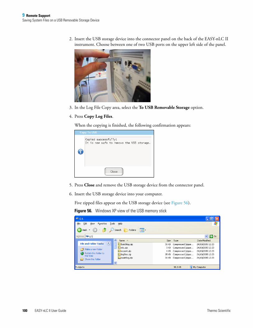
9 Remote SupportSaving System Files on a USB Removable Storage Device
100 EASY-nLC II User Guide Thermo Scientific
2. Insert the USB storage device into the connector panel on the back of the EASY-nLC II instrument. Choose between one of two USB ports on the upper left side of the panel.
3. In the Log File Copy area, select the To USB Removable Storage option.
4. Press Copy Log Files.
When the copying is finished, the following confirmation appears:
5. Press Close and remove the USB storage device from the connector panel.
6. Insert the USB storage device into your computer.
Five zipped files appear on the USB storage device (see Figure 56).
Figure 56. Windows XP view of the USB memory stick

9 Remote SupportSaving System Files on a USB Removable Storage Device
Thermo Scientific EASY-nLC II User Guide 101
The files are as follows:
If you have problems with your system, forward the files to Thermo Fisher Scientific Technical Support for assistance.
batchlog.zip Contains one folder for each batch you have run with information on samples, methods, and EASY-nLC II device performance.
etc.zip Contains system configuration files.
export.zip Contains exported batches and methods per user and system backup.
logfiles.zip Contains system log files with information on overall system performance.
maintlog.zip Contains one folder for each maintenance script you have run with information on EASY-nLC II device performance.

Thermo Scientific EASY-nLC II User Guide 103
10
Maintenance
This chapter provides various maintenance schedules for the EASY-nLC II system, and describes the system’s built-in maintenance scripts and when to use them. Consistent use of these procedures will help ensure the longevity of your instrument.
Daily MaintenanceCheck the solvent levels on a daily basis.
To check solvent levels
1. Visually inspect solvent bottle A, solvent bottle B, and the autosampler bottle in position W3 (and the bottles in position W1 and W2 if used). Refill if necessary.
(ASA autosampler only) Make sure that the solvent level in the W1, W2, and W3 autosampler bottles never falls under 2/3 of the bottle volume.
2. Visually inspect the autosampler wash bottle in position W4 and the waste container in the pump compartment, and empty if necessary.
3. Run the Purge Solvent and Flush Air scripts with two purge iterations or until flush volumes fall below 10 μL.
Contents
• Daily Maintenance
• Quarterly Maintenance
• Yearly Maintenance
• Maintenance Scripts
Tip You can also inspect the purity of the solvent to ensure no visible precipitates have formed that might lead to blockages in the pump line.
10 MaintenanceQuarterly Maintenance
104 EASY-nLC II User Guide Thermo Scientific
Quarterly MaintenancePerform the following procedures quarterly (every three months).
To check instrument back pressure
Run the Back Pressure script for both solvents.
To check the cooler temperature
Check that the plate temperature is at its set point or approximately 18 to 20 °C (64 to 68 °F) below ambient temperature (readout on the Home > Overview page).
To check autosampler pickup
Run the Sample Pickup script to check the autosampler pickup function.
To check the EASY-nLC II system for leaks
Run the Leaks script for “A+B” and for “System,” to check for and pinpoint instrument leaks.
To check the check valves
Run the Purge Solvent script while checking that solvents are exiting the A and B waste tubing and passing into the waste container when the pumps are ejecting. Make sure that no solvents are going into the pump through these tubes during refill.
Yearly MaintenanceSchedule the following procedures once a year.
To exchange low pressure solvent filters and high pressure inline filters
Thoroughly clean new solvent filters before use as these can be a contamination source.
To check flow sensor calibration
Run the Flow Sensor calibration script with the Inspection Only parameter enabled. This checks that the flow sensor calibration is working. Enter 30 minutes for Period.
IMPORTANT Check the valve rotor shifts regularly. When the valve rotor shifts exceed 6000, Thermo Fisher Scientific recommends checking the system for leaks. From this point forward, perform leak tests every 1000 shifts and exchange the rotor when the leak test fails.
10 MaintenanceMaintenance Scripts
Thermo Scientific EASY-nLC II User Guide 105
Maintenance ScriptsTo execute all listed maintenance scripts
1. In the EASY-nLC II application, choose Maintenance > Scripts.
2. Select a category and then a name for the specific operation.
You can also schedule some of the scripts for execution using the job queue.
Each of the following sections combines the category with the actual script name.
• Prepare – Purge Solvent
• Prepare – Flush Air
• Prepare – Precolumn Equilibration
• Prepare – Analytical Col Equilibration
• Prepare – Isocratic Flow
• Test – MS Connection
• Test – Sample Pickup
• Test – Leaks
• Test – Valve Check
• Test – Back Pressure
• Test – Autosampler Torque
• Calibrate – Valve Tune
• Calibrate – Flow Sensors
• Calibrate – Reset Pressure Sensor
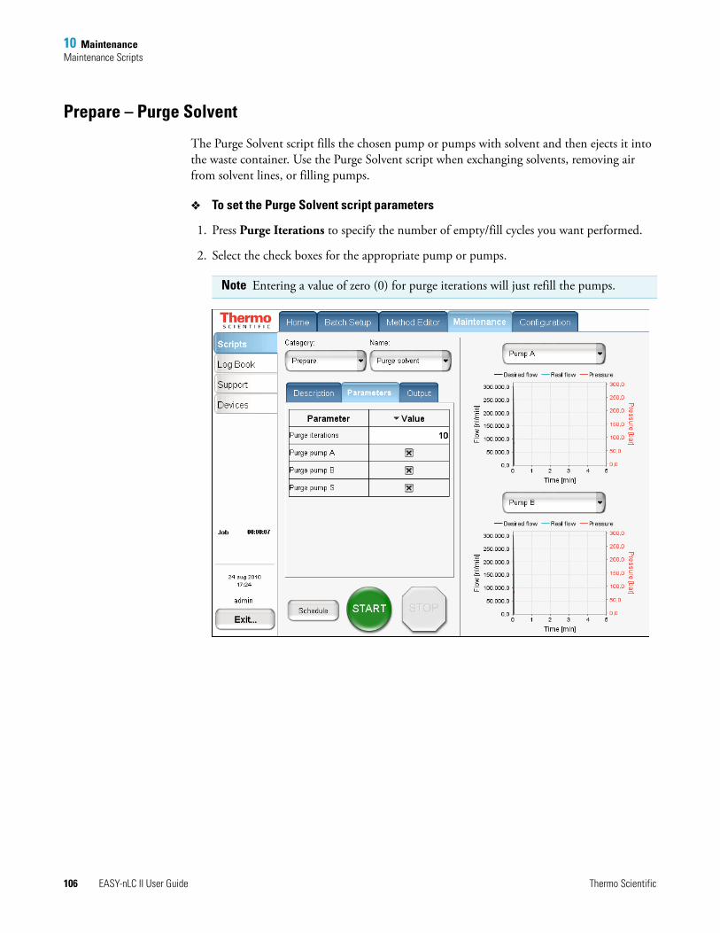
10 MaintenanceMaintenance Scripts
106 EASY-nLC II User Guide Thermo Scientific
Prepare – Purge Solvent
The Purge Solvent script fills the chosen pump or pumps with solvent and then ejects it into the waste container. Use the Purge Solvent script when exchanging solvents, removing air from solvent lines, or filling pumps.
To set the Purge Solvent script parameters
1. Press Purge Iterations to specify the number of empty/fill cycles you want performed.
2. Select the check boxes for the appropriate pump or pumps.
Note Entering a value of zero (0) for purge iterations will just refill the pumps.
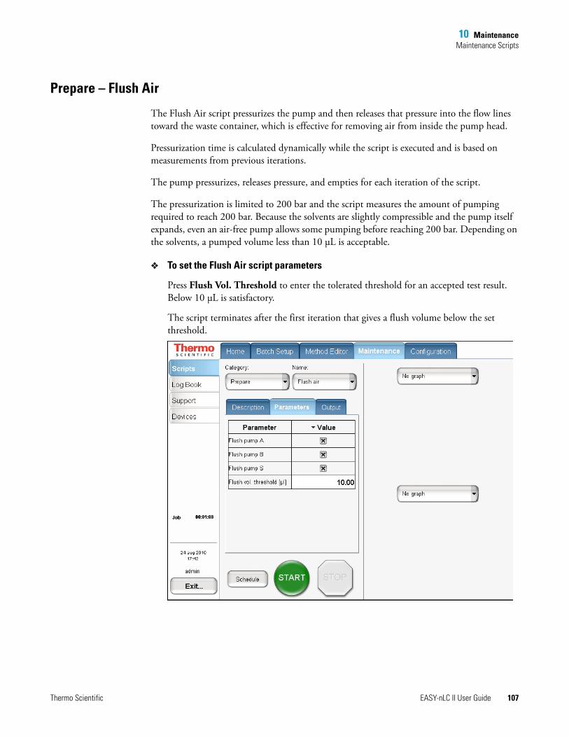
10 MaintenanceMaintenance Scripts
Thermo Scientific EASY-nLC II User Guide 107
Prepare – Flush Air
The Flush Air script pressurizes the pump and then releases that pressure into the flow lines toward the waste container, which is effective for removing air from inside the pump head.
Pressurization time is calculated dynamically while the script is executed and is based on measurements from previous iterations.
The pump pressurizes, releases pressure, and empties for each iteration of the script.
The pressurization is limited to 200 bar and the script measures the amount of pumping required to reach 200 bar. Because the solvents are slightly compressible and the pump itself expands, even an air-free pump allows some pumping before reaching 200 bar. Depending on the solvents, a pumped volume less than 10 μL is acceptable.
To set the Flush Air script parameters
Press Flush Vol. Threshold to enter the tolerated threshold for an accepted test result. Below 10 μL is satisfactory.
The script terminates after the first iteration that gives a flush volume below the set threshold.
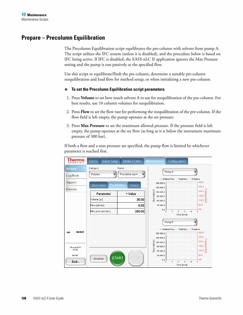
10 MaintenanceMaintenance Scripts
108 EASY-nLC II User Guide Thermo Scientific
Prepare – Precolumn Equilibration
The Precolumn Equilibration script equilibrates the pre-column with solvent from pump A. The script utilizes the IFC system (unless it is disabled), and the procedure below is based on IFC being active. If IFC is disabled, the EASY-nLC II application ignores the Max Pressure setting and the pump is run passively at the specified flow.
Use this script to equilibrate/flush the pre-column, determine a suitable pre-column reequilibration and load flow for method setup, or when initializing a new pre-column.
To set the Precolumn Equilibration script parameters
1. Press Volume to set how much solvent A to use for reequilibration of the pre-column. For best results, use 10 column volumes for reequilibration.
2. Press Flow to set the flow rate for performing the reequilibration of the pre-column. If the flow field is left empty, the pump operates at the set pressure.
3. Press Max Pressure to set the maximum allowed pressure. If the pressure field is left empty, the pump operates at the set flow (as long as it is below the instrument maximum pressure of 300 bar).
If both a flow and a max pressure are specified, the pump flow is limited by whichever parameter is reached first.
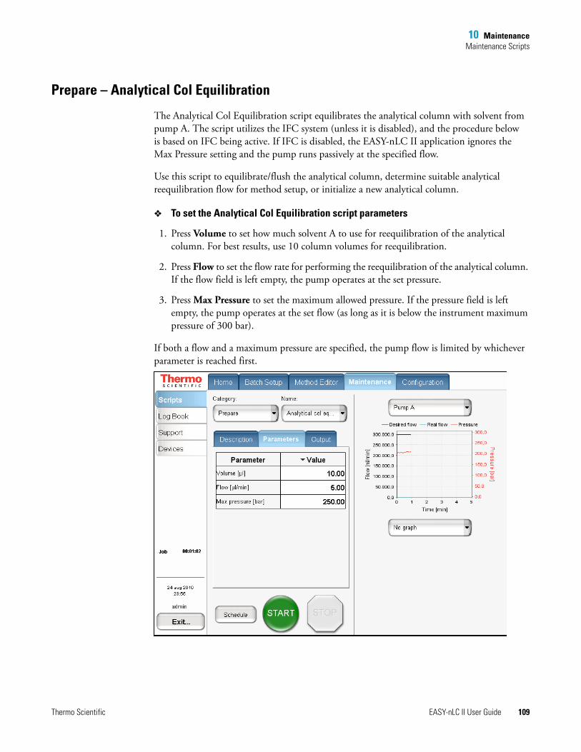
10 MaintenanceMaintenance Scripts
Thermo Scientific EASY-nLC II User Guide 109
Prepare – Analytical Col Equilibration
The Analytical Col Equilibration script equilibrates the analytical column with solvent from pump A. The script utilizes the IFC system (unless it is disabled), and the procedure below is based on IFC being active. If IFC is disabled, the EASY-nLC II application ignores the Max Pressure setting and the pump runs passively at the specified flow.
Use this script to equilibrate/flush the analytical column, determine suitable analytical reequilibration flow for method setup, or initialize a new analytical column.
To set the Analytical Col Equilibration script parameters
1. Press Volume to set how much solvent A to use for reequilibration of the analytical column. For best results, use 10 column volumes for reequilibration.
2. Press Flow to set the flow rate for performing the reequilibration of the analytical column. If the flow field is left empty, the pump operates at the set pressure.
3. Press Max Pressure to set the maximum allowed pressure. If the pressure field is left empty, the pump operates at the set flow (as long as it is below the instrument maximum pressure of 300 bar).
If both a flow and a maximum pressure are specified, the pump flow is limited by whichever parameter is reached first.
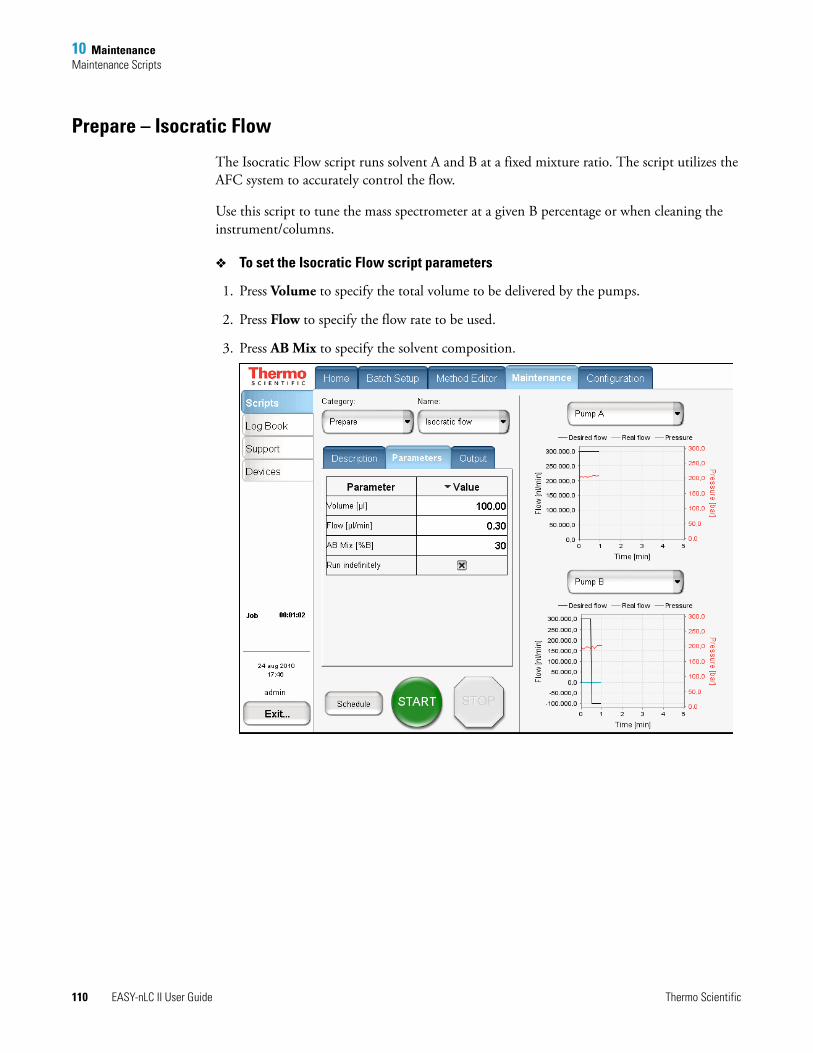
10 MaintenanceMaintenance Scripts
110 EASY-nLC II User Guide Thermo Scientific
Prepare – Isocratic Flow
The Isocratic Flow script runs solvent A and B at a fixed mixture ratio. The script utilizes the AFC system to accurately control the flow.
Use this script to tune the mass spectrometer at a given B percentage or when cleaning the instrument/columns.
To set the Isocratic Flow script parameters
1. Press Volume to specify the total volume to be delivered by the pumps.
2. Press Flow to specify the flow rate to be used.
3. Press AB Mix to specify the solvent composition.
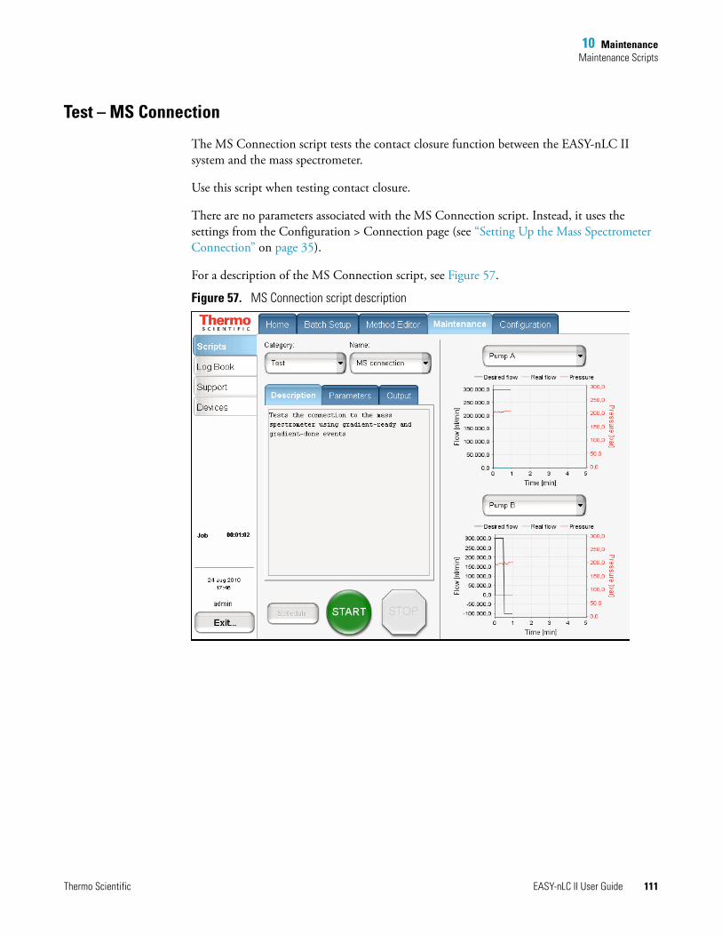
10 MaintenanceMaintenance Scripts
Thermo Scientific EASY-nLC II User Guide 111
Test – MS Connection
The MS Connection script tests the contact closure function between the EASY-nLC II system and the mass spectrometer.
Use this script when testing contact closure.
There are no parameters associated with the MS Connection script. Instead, it uses the settings from the Configuration > Connection page (see “Setting Up the Mass Spectrometer Connection” on page 35).
For a description of the MS Connection script, see Figure 57.
Figure 57. MS Connection script description
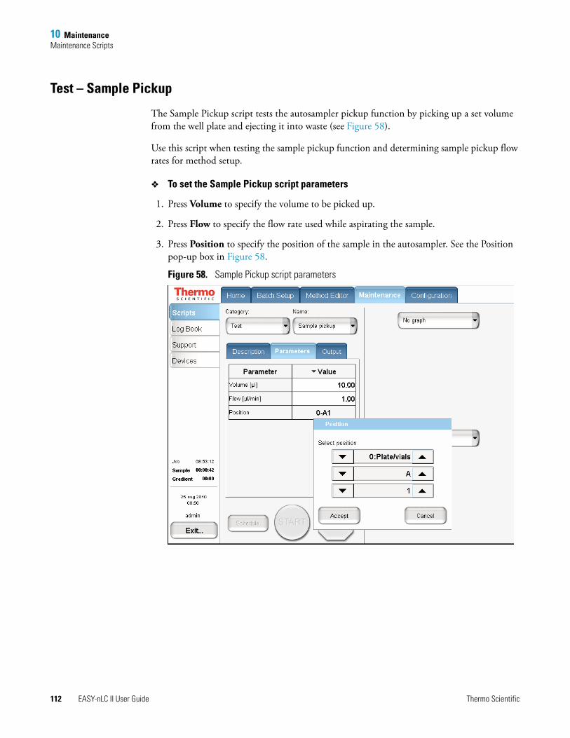
10 MaintenanceMaintenance Scripts
112 EASY-nLC II User Guide Thermo Scientific
Test – Sample Pickup
The Sample Pickup script tests the autosampler pickup function by picking up a set volume from the well plate and ejecting it into waste (see Figure 58).
Use this script when testing the sample pickup function and determining sample pickup flow rates for method setup.
To set the Sample Pickup script parameters
1. Press Volume to specify the volume to be picked up.
2. Press Flow to specify the flow rate used while aspirating the sample.
3. Press Position to specify the position of the sample in the autosampler. See the Position pop-up box in Figure 58.
Figure 58. Sample Pickup script parameters
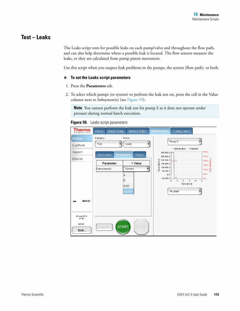
10 MaintenanceMaintenance Scripts
Thermo Scientific EASY-nLC II User Guide 113
Test – Leaks
The Leaks script tests for possible leaks on each pump/valve and throughout the flow path, and can also help determine where a possible leak is located. The flow sensors measure the leaks, or they are calculated from pump piston movement.
Use this script when you suspect leak problems in the pumps, the system (flow path), or both.
To set the Leaks script parameters
1. Press the Parameters tab.
2. To select which pumps (or system) to perform the leak test on, press the cell in the Value column next to Subsystem(s) (see Figure 59).
Figure 59. Leaks script parameters
Note You cannot perform the leak test for pump S as it does not operate under pressure during normal batch execution.
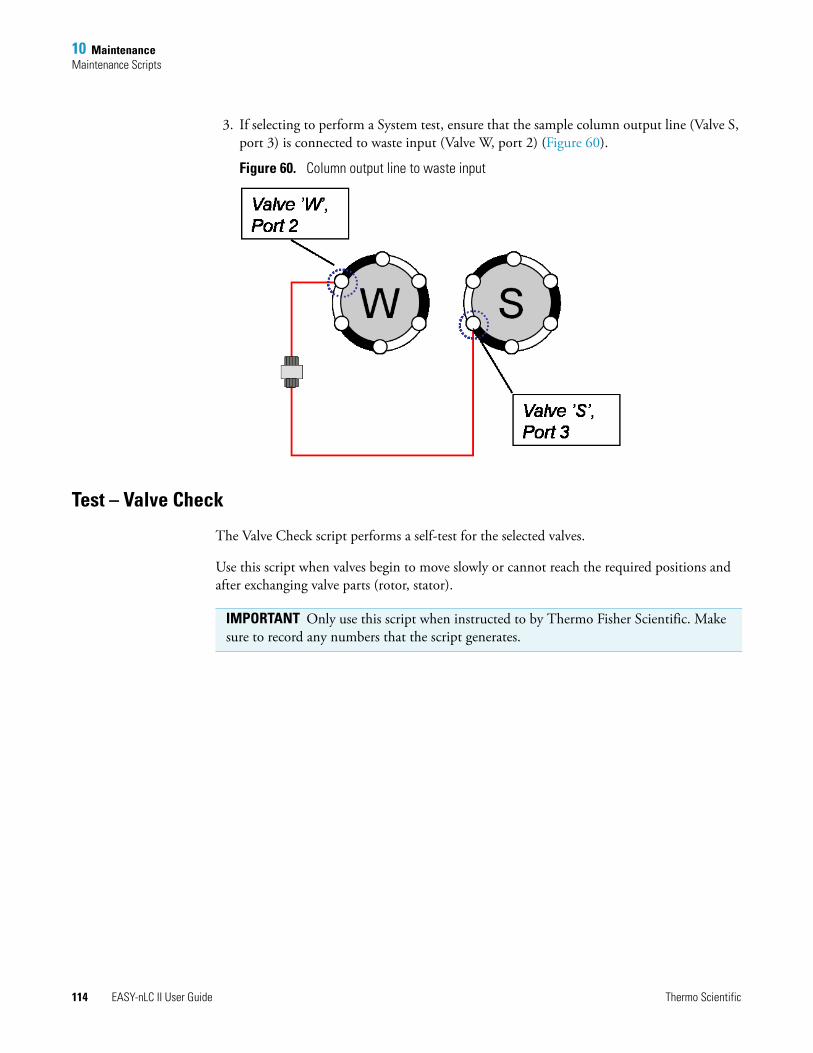
10 MaintenanceMaintenance Scripts
114 EASY-nLC II User Guide Thermo Scientific
3. If selecting to perform a System test, ensure that the sample column output line (Valve S, port 3) is connected to waste input (Valve W, port 2) (Figure 60).
Figure 60. Column output line to waste input
Test – Valve Check
The Valve Check script performs a self-test for the selected valves.
Use this script when valves begin to move slowly or cannot reach the required positions and after exchanging valve parts (rotor, stator).
IMPORTANT Only use this script when instructed to by Thermo Fisher Scientific. Make sure to record any numbers that the script generates.
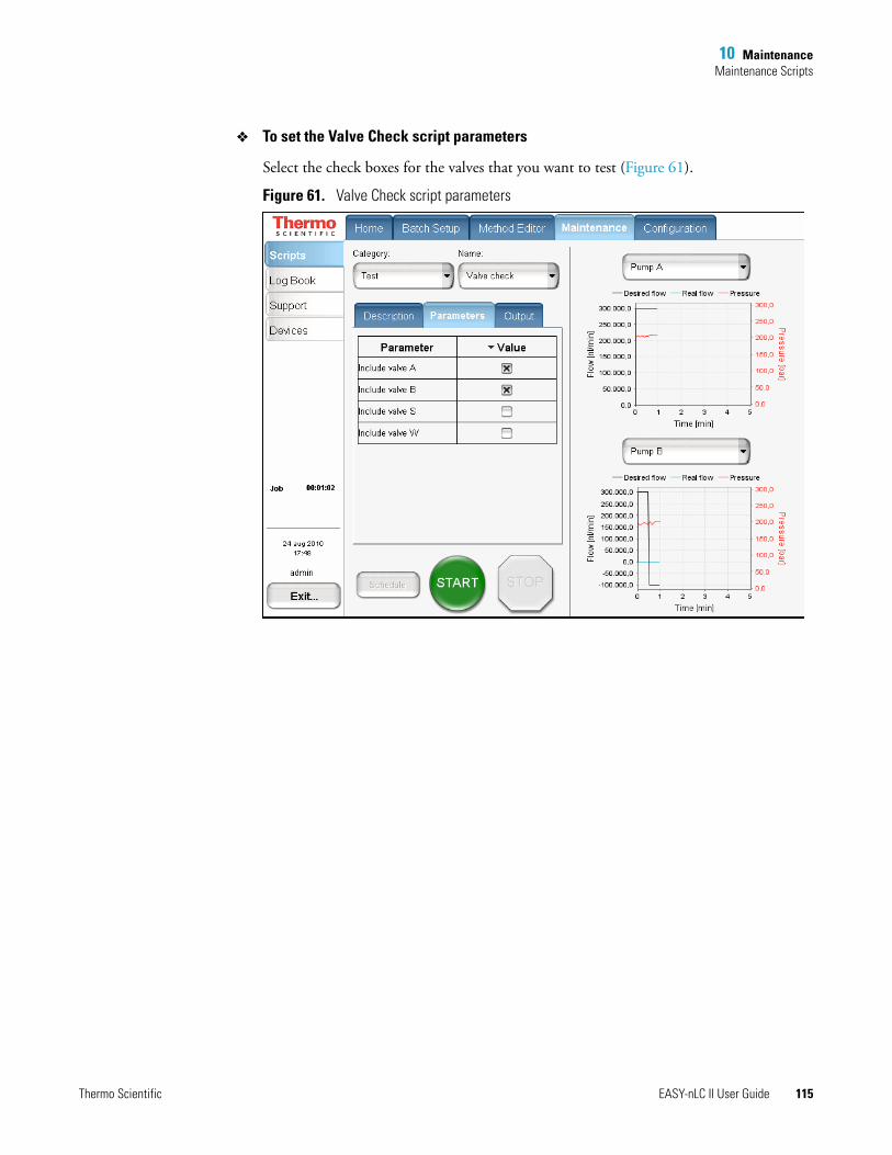
10 MaintenanceMaintenance Scripts
Thermo Scientific EASY-nLC II User Guide 115
To set the Valve Check script parameters
Select the check boxes for the valves that you want to test (Figure 61).
Figure 61. Valve Check script parameters
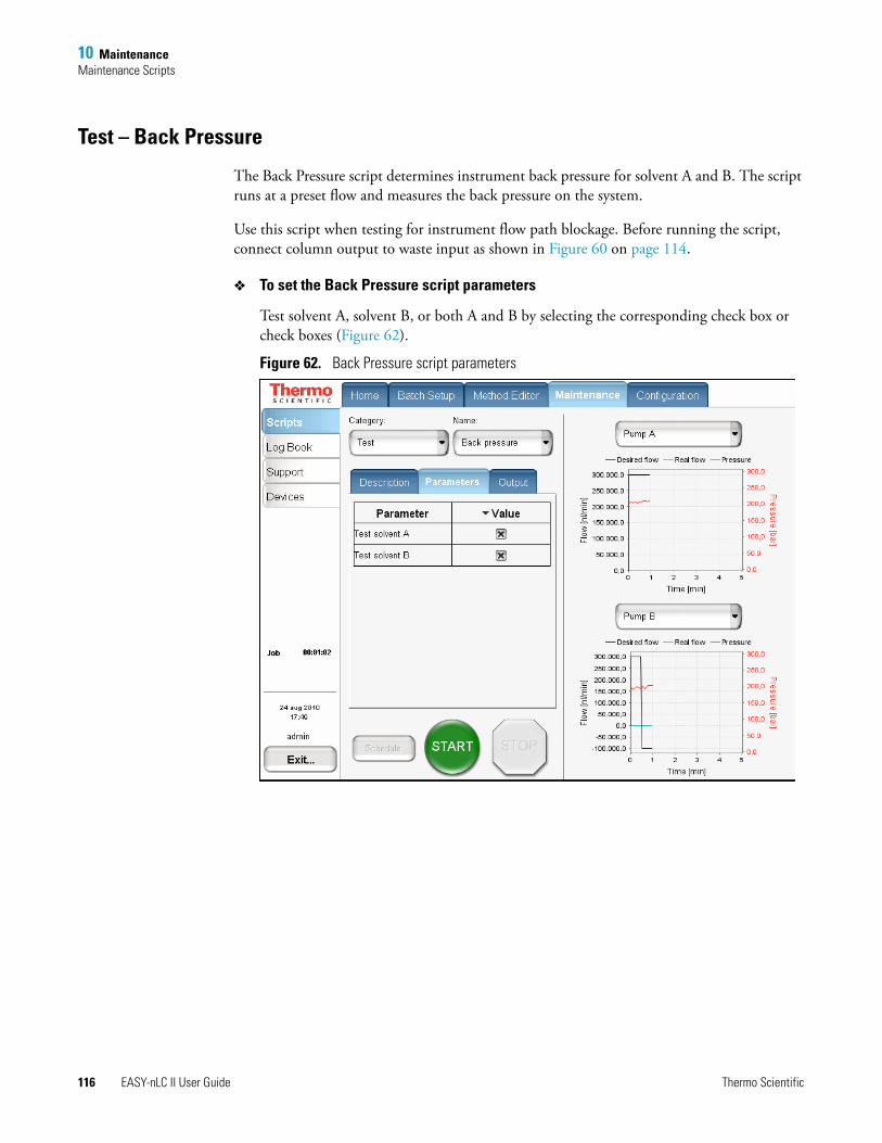
10 MaintenanceMaintenance Scripts
116 EASY-nLC II User Guide Thermo Scientific
Test – Back Pressure
The Back Pressure script determines instrument back pressure for solvent A and B. The script runs at a preset flow and measures the back pressure on the system.
Use this script when testing for instrument flow path blockage. Before running the script, connect column output to waste input as shown in Figure 60 on page 114.
To set the Back Pressure script parameters
Test solvent A, solvent B, or both A and B by selecting the corresponding check box or check boxes (Figure 62).
Figure 62. Back Pressure script parameters
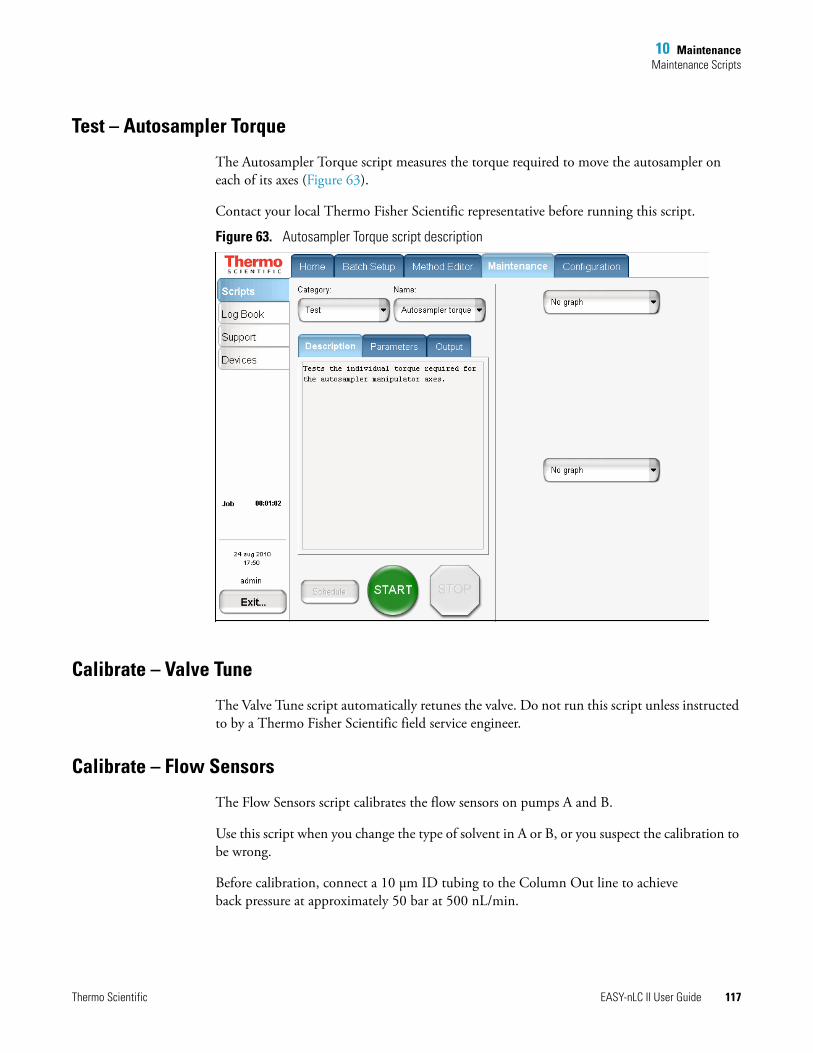
10 MaintenanceMaintenance Scripts
Thermo Scientific EASY-nLC II User Guide 117
Test – Autosampler Torque
The Autosampler Torque script measures the torque required to move the autosampler on each of its axes (Figure 63).
Contact your local Thermo Fisher Scientific representative before running this script.
Figure 63. Autosampler Torque script description
Calibrate – Valve Tune
The Valve Tune script automatically retunes the valve. Do not run this script unless instructed to by a Thermo Fisher Scientific field service engineer.
Calibrate – Flow Sensors
The Flow Sensors script calibrates the flow sensors on pumps A and B.
Use this script when you change the type of solvent in A or B, or you suspect the calibration to be wrong.
Before calibration, connect a 10 μm ID tubing to the Column Out line to achieve back pressure at approximately 50 bar at 500 nL/min.
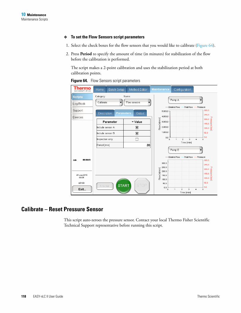
10 MaintenanceMaintenance Scripts
118 EASY-nLC II User Guide Thermo Scientific
To set the Flow Sensors script parameters
1. Select the check boxes for the flow sensors that you would like to calibrate (Figure 64).
2. Press Period to specify the amount of time (in minutes) for stabilization of the flow before the calibration is performed.
The script makes a 2-point calibration and uses the stabilization period at both calibration points.
Figure 64. Flow Sensors script parameters
Calibrate – Reset Pressure Sensor
This script auto-zeroes the pressure sensor. Contact your local Thermo Fisher Scientific Technical Support representative before running this script.

Thermo Scientific EASY-nLC II User Guide 119
A
Specifications
This appendix contains the following specifications for the EASY-nLC II system as well as a flow line schematic.
Performance SpecificationsSee Table 15 for performance specifications.
Contents
• Performance Specifications
• Technical Specifications
• Flow Line Diagram
Table 15. Performance specification (Sheet 1 of 2)
Item Specification
Flow range (gradient) 20–2000 nL/minRecommended: 100–1000 nL/min
Flow while loading and equilibrating
Up to 100 μL/min
Pressure range 0–300 bar
Retention time reproducibility (RT RSD)
Recommended flow range: 0.1 to 0.4% Typically better than 1% outside recommended flow range
Peak widths Typically 3–5 s fwhm, using EASY-column™ nano-bore columns as supplied at delivery
For more information, go to www.proxeon.com/productrange/nano_lc_easy_columns/
Carryover Typically < 0.05%Conditions: Injection of 100 fmol tryptic digests of BSA on EASY-columns as supplied at delivery and by using the Standard Wash procedure for the autosampler
Autosampler pickup volume range
100–18000 nL, with standard loop100–58000 nL, with up to 60 μL loop
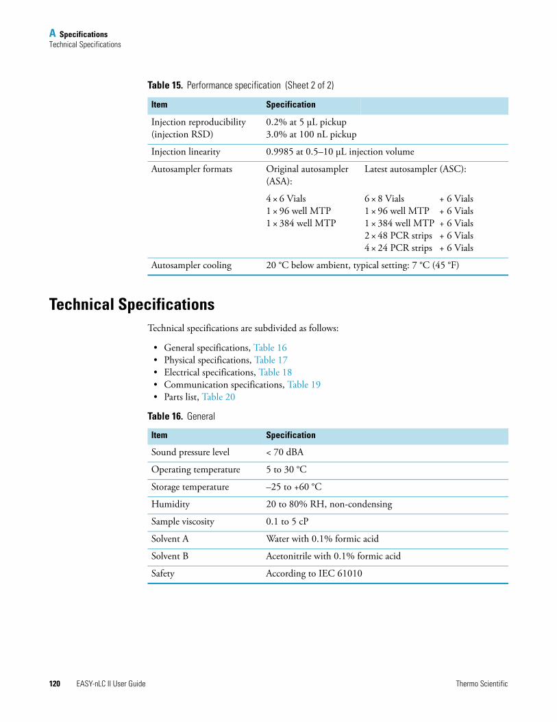
A SpecificationsTechnical Specifications
120 EASY-nLC II User Guide Thermo Scientific
Technical SpecificationsTechnical specifications are subdivided as follows:
• General specifications, Table 16• Physical specifications, Table 17• Electrical specifications, Table 18• Communication specifications, Table 19• Parts list, Table 20
Injection reproducibility (injection RSD)
0.2% at 5 μL pickup3.0% at 100 nL pickup
Injection linearity 0.9985 at 0.5–10 μL injection volume
Autosampler formats Original autosampler (ASA):
Latest autosampler (ASC):
4 × 6 Vials 1 × 96 well MTP1 × 384 well MTP
6 × 8 Vials + 6 Vials1 × 96 well MTP + 6 Vials1 × 384 well MTP + 6 Vials2 × 48 PCR strips + 6 Vials4 × 24 PCR strips + 6 Vials
Autosampler cooling 20 °C below ambient, typical setting: 7 °C (45 °F)
Table 15. Performance specification (Sheet 2 of 2)
Item Specification
Table 16. General
Item Specification
Sound pressure level < 70 dBA
Operating temperature 5 to 30 °C
Storage temperature –25 to +60 °C
Humidity 20 to 80% RH, non-condensing
Sample viscosity 0.1 to 5 cP
Solvent A Water with 0.1% formic acid
Solvent B Acetonitrile with 0.1% formic acid
Safety According to IEC 61010
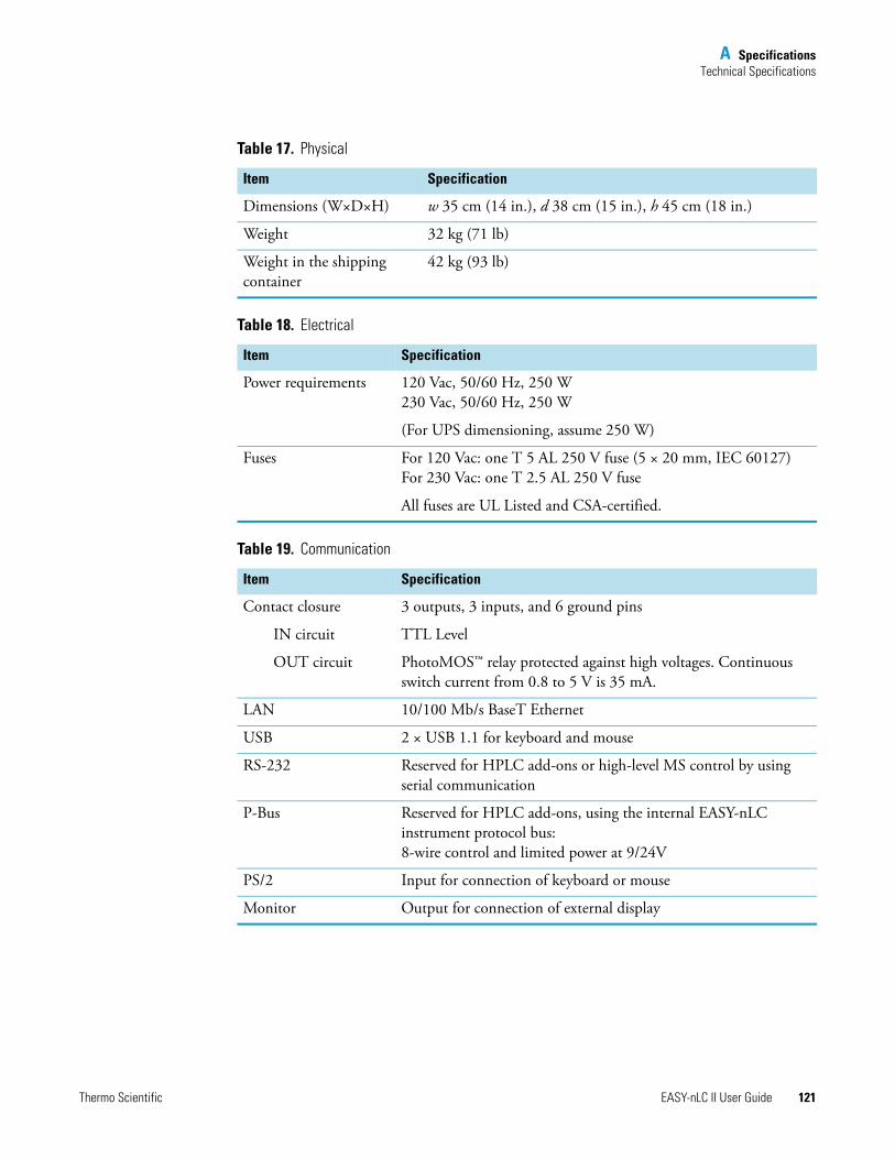
A SpecificationsTechnical Specifications
Thermo Scientific EASY-nLC II User Guide 121
Table 17. Physical
Item Specification
Dimensions (W×D×H) w 35 cm (14 in.), d 38 cm (15 in.), h 45 cm (18 in.)
Weight 32 kg (71 lb)
Weight in the shipping container
42 kg (93 lb)
Table 18. Electrical
Item Specification
Power requirements 120 Vac, 50/60 Hz, 250 W230 Vac, 50/60 Hz, 250 W
(For UPS dimensioning, assume 250 W)
Fuses For 120 Vac: one T 5 AL 250 V fuse (5 × 20 mm, IEC 60127)For 230 Vac: one T 2.5 AL 250 V fuse
All fuses are UL Listed and CSA-certified.
Table 19. Communication
Item Specification
Contact closure 3 outputs, 3 inputs, and 6 ground pins
IN circuit TTL Level
OUT circuit PhotoMOS™ relay protected against high voltages. Continuous switch current from 0.8 to 5 V is 35 mA.
LAN 10/100 Mb/s BaseT Ethernet
USB 2 × USB 1.1 for keyboard and mouse
RS-232 Reserved for HPLC add-ons or high-level MS control by using serial communication
P-Bus Reserved for HPLC add-ons, using the internal EASY-nLC instrument protocol bus:8-wire control and limited power at 9/24V
PS/2 Input for connection of keyboard or mouse
Monitor Output for connection of external display
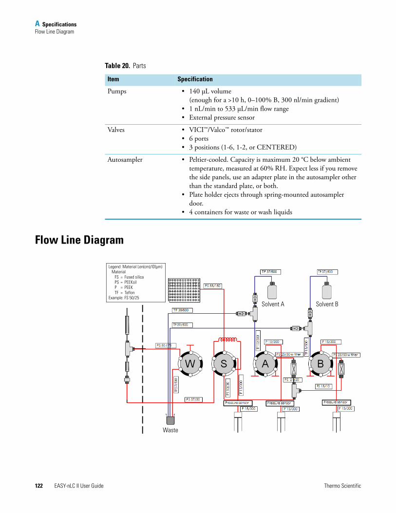
A SpecificationsFlow Line Diagram
122 EASY-nLC II User Guide Thermo Scientific
Flow Line Diagram
Table 20. Parts
Item Specification
Pumps • 140 μL volume (enough for a >10 h, 0–100% B, 300 nl/min gradient)
• 1 nL/min to 533 μL/min flow range• External pressure sensor
Valves • VICI™/Valco™ rotor/stator• 6 ports• 3 positions (1-6, 1-2, or CENTERED)
Autosampler • Peltier-cooled. Capacity is maximum 20 °C below ambient temperature, measured at 60% RH. Expect less if you remove the side panels, use an adapter plate in the autosampler other than the standard plate, or both.
• Plate holder ejects through spring-mounted autosampler door.
• 4 containers for waste or wash liquids
Solvent A Solvent B
Waste
Legend: Material Len(cm)/ID(μm)Material
FS = Fused silicaPS = PEEKsilP = PEEKTF = Teflon
Example: FS 50/25

Thermo Scientific EASY-nLC II User Guide 123
B
Miscellaneous
This appendix contains information you might refer to periodically, including how to replace the main power fuse, how to install an external device such as Advion RePlay™, a consumable parts list, and transport and disposal instructions.
Cleaning MaterialsWhen cleaning the outside of the EASY-nLC II instrument, use a mild detergent and a clean cloth.
EASY-nLC II Consumable Parts ListThese EASY-nLC II parts are consumable parts and not covered by the normal first year Limited Warranty offered by Thermo Fisher Scientific, or any other service contract agreement containing extended warranty coverage.
• All flow lines including Tee-pieces and fittings (nuts, ferrules, sleeves, and valve blank stops)
• Check valves
• Solvent filters, inline filters, and all associated filter holders
• Pump piston seals
• Valve rotors and stators
Contents
• Cleaning Materials
• EASY-nLC II Consumable Parts List
• Replacing the Main Power Fuse
• Installing and Using the RePlay External Device
• Declaration of Contamination
• Transport Instructions
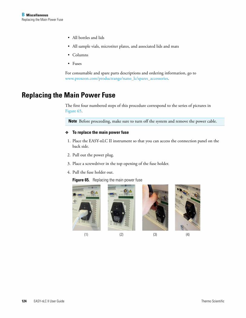
B MiscellaneousReplacing the Main Power Fuse
124 EASY-nLC II User Guide Thermo Scientific
• All bottles and lids
• All sample vials, microtiter plates, and associated lids and mats
• Columns
• Fuses
For consumable and spare parts descriptions and ordering information, go to www.proxeon.com/productrange/nano_lc/spares_accessories.
Replacing the Main Power FuseThe first four numbered steps of this procedure correspond to the series of pictures in Figure 65.
To replace the main power fuse
1. Place the EASY-nLC II instrument so that you can access the connection panel on the back side.
2. Pull out the power plug.
3. Place a screwdriver in the top opening of the fuse holder.
4. Pull the fuse holder out.
Figure 65. Replacing the main power fuse
Note Before proceeding, make sure to turn off the system and remove the power cable.
(1) (2) (3) (4)
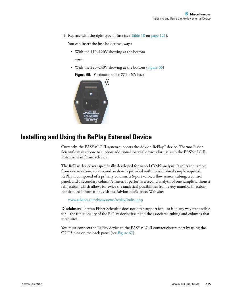
B MiscellaneousInstalling and Using the RePlay External Device
Thermo Scientific EASY-nLC II User Guide 125
5. Replace with the right type of fuse (see Table 18 on page 121).
You can insert the fuse holder two ways:
• With the 110–120V showing at the bottom
–or–
• With the 220–240V showing at the bottom (Figure 66)
Figure 66. Positioning of the 220–240V fuse
Installing and Using the RePlay External DeviceCurrently, the EASY-nLC II system supports the Advion RePlay™ device. Thermo Fisher Scientific may choose to support additional external devices for use with the EASY-nLC II instrument in future releases.
The RePlay device was specifically developed for nano LC/MS analysis. It splits the sample from one injection, so a second analysis is provided with no additional sample required. RePlay is composed of a primary column, a 6-port valve, a flow sensor, tubing, a control panel, and a secondary column/emitter. It performs a second analysis of one sample without a reinjection, which allows for twice the analytical possibilities from every nanoLC injection. For detailed information, visit the Advion BioSciences Web site:
www.advion.com/biosystems/replay/index.php
Disclaimer: Thermo Fisher Scientific does not offer support for—or is in any way responsible for—the functionality of the RePlay device itself and the associated tubing and columns that it requires.
You must connect the RePlay device to the EASY-nLC II contact closure port by using the OUT3 pins on the back panel (see Figure 67).
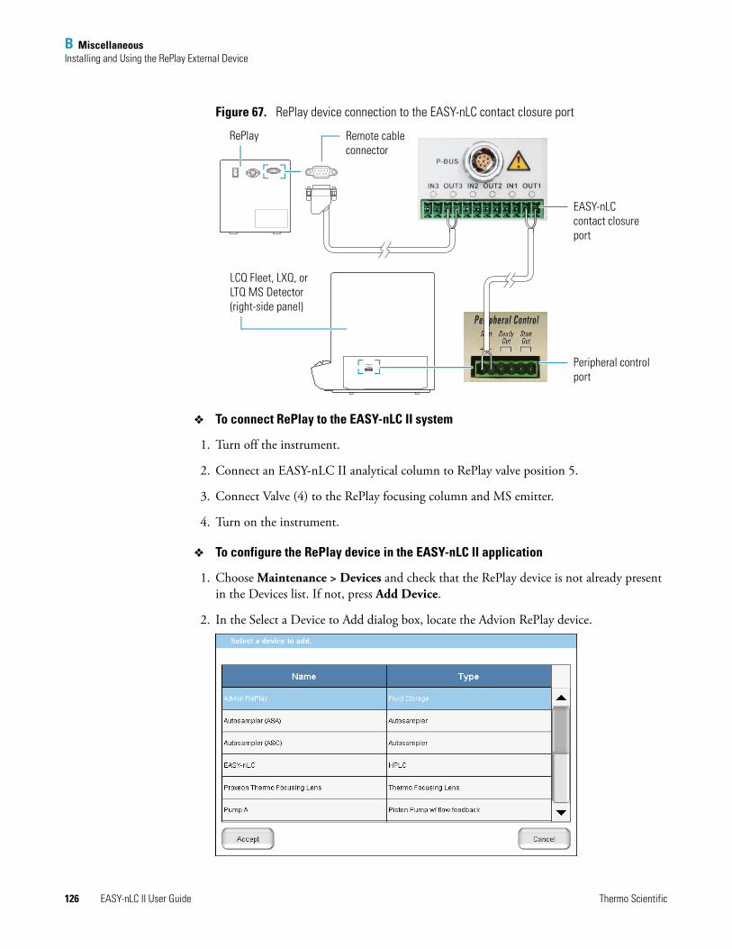
B MiscellaneousInstalling and Using the RePlay External Device
126 EASY-nLC II User Guide Thermo Scientific
Figure 67. RePlay device connection to the EASY-nLC contact closure port
To connect RePlay to the EASY-nLC II system
1. Turn off the instrument.
2. Connect an EASY-nLC II analytical column to RePlay valve position 5.
3. Connect Valve (4) to the RePlay focusing column and MS emitter.
4. Turn on the instrument.
To configure the RePlay device in the EASY-nLC II application
1. Choose Maintenance > Devices and check that the RePlay device is not already present in the Devices list. If not, press Add Device.
2. In the Select a Device to Add dialog box, locate the Advion RePlay device.
Power In
Mech. Pumps/Accessory
Main Power
Peripheral Control
Ethernet
Electronics Normal
Service
Reset
Analog Input
StartIn
100 Base T
ReadyOut
1V MAX 10V MAX
StartOut
On230 V AC
10 A
A 5.5 MAX
A 5.5 MAX
Off
EASY-nLC contact closure port
Peripheral control port
LCQ Fleet, LXQ, or LTQ MS Detector (right-side panel)
Remote cable connector
RePlay
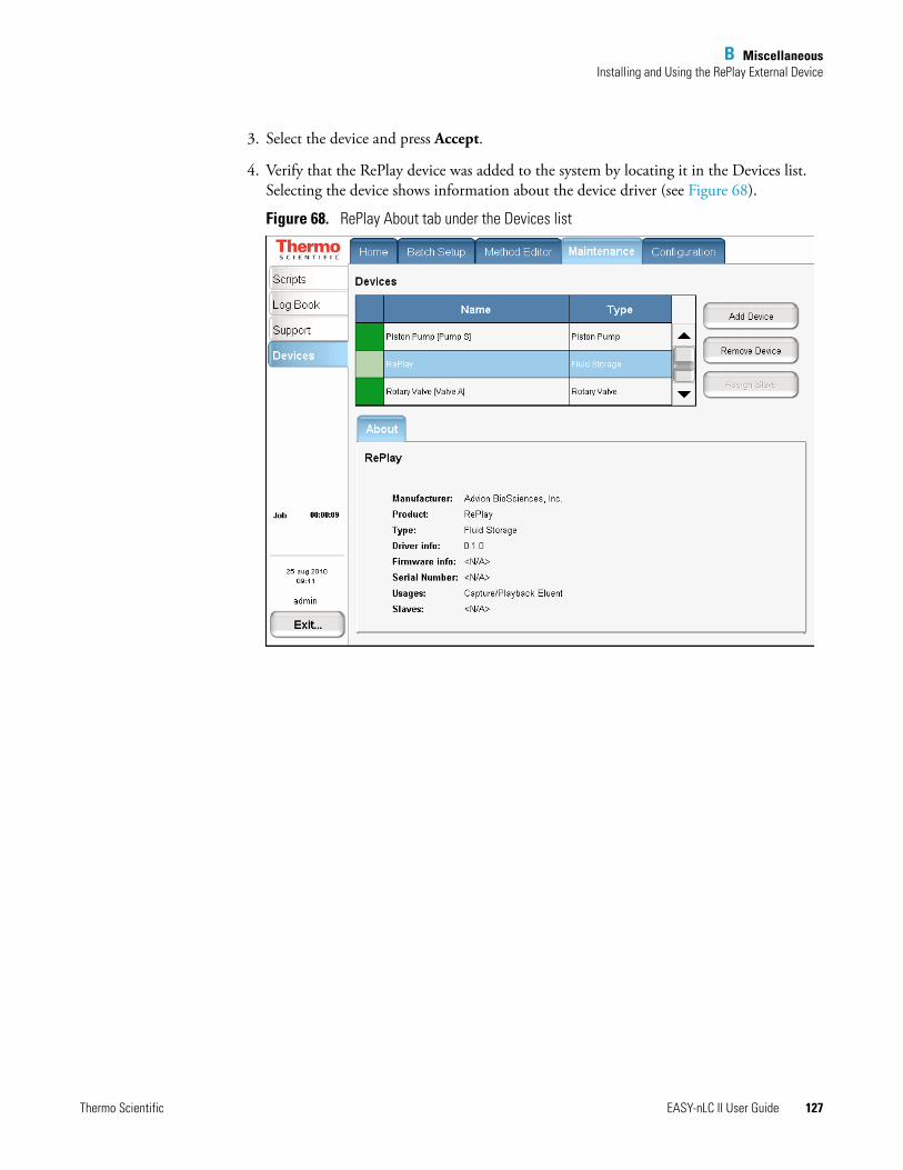
B MiscellaneousInstalling and Using the RePlay External Device
Thermo Scientific EASY-nLC II User Guide 127
3. Select the device and press Accept.
4. Verify that the RePlay device was added to the system by locating it in the Devices list. Selecting the device shows information about the device driver (see Figure 68).
Figure 68. RePlay About tab under the Devices list
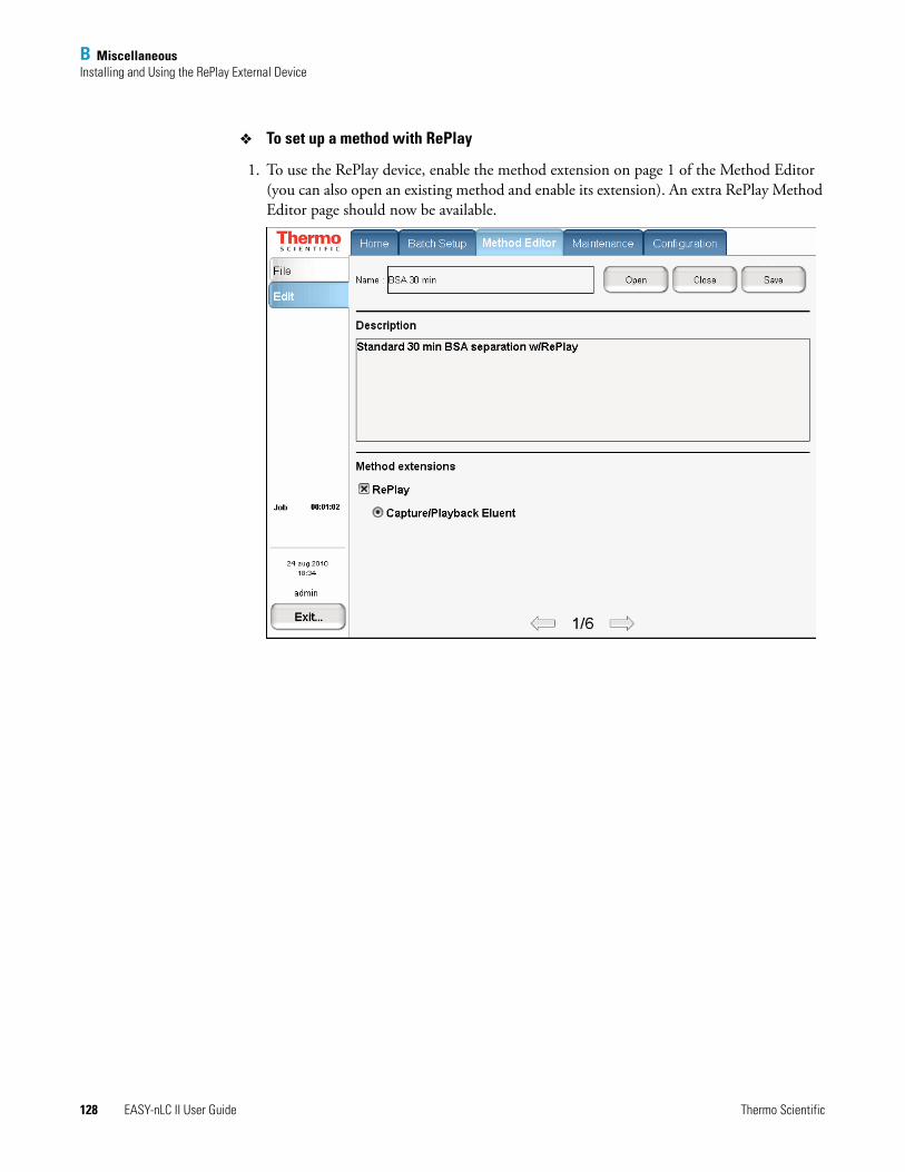
B MiscellaneousInstalling and Using the RePlay External Device
128 EASY-nLC II User Guide Thermo Scientific
To set up a method with RePlay
1. To use the RePlay device, enable the method extension on page 1 of the Method Editor (you can also open an existing method and enable its extension). An extra RePlay Method Editor page should now be available.
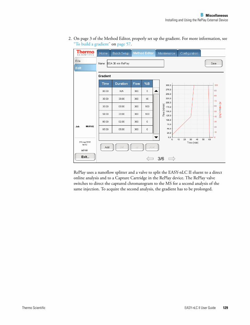
B MiscellaneousInstalling and Using the RePlay External Device
Thermo Scientific EASY-nLC II User Guide 129
2. On page 3 of the Method Editor, properly set up the gradient. For more information, see “To build a gradient” on page 57.
RePlay uses a nanoflow splitter and a valve to split the EASY-nLC II eluent to a direct online analysis and to a Capture Cartridge in the RePlay device. The RePlay valve switches to direct the captured chromatogram to the MS for a second analysis of the same injection. To acquire the second analysis, the gradient has to be prolonged.
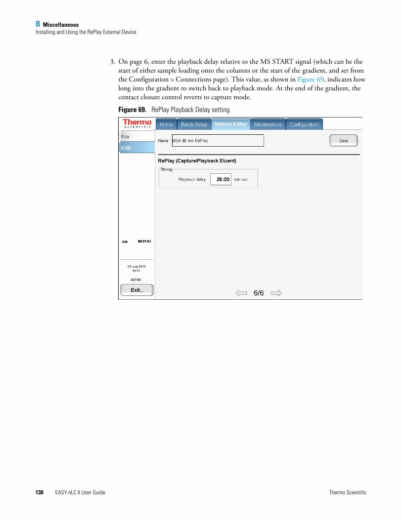
B MiscellaneousInstalling and Using the RePlay External Device
130 EASY-nLC II User Guide Thermo Scientific
3. On page 6, enter the playback delay relative to the MS START signal (which can be the start of either sample loading onto the columns or the start of the gradient, and set from the Configuration > Connections page). This value, as shown in Figure 69, indicates how long into the gradient to switch back to playback mode. At the end of the gradient, the contact closure control reverts to capture mode.
Figure 69. RePlay Playback Delay setting
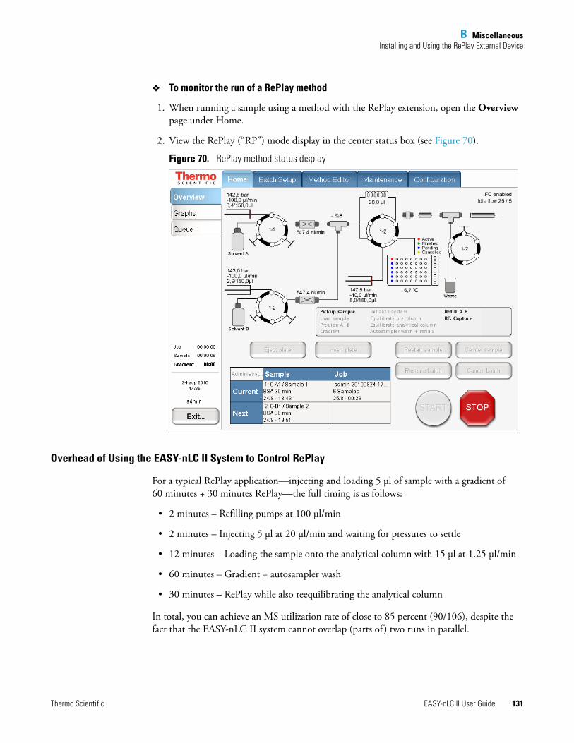
B MiscellaneousInstalling and Using the RePlay External Device
Thermo Scientific EASY-nLC II User Guide 131
To monitor the run of a RePlay method
1. When running a sample using a method with the RePlay extension, open the Overview page under Home.
2. View the RePlay (“RP”) mode display in the center status box (see Figure 70).
Figure 70. RePlay method status display
Overhead of Using the EASY-nLC II System to Control RePlay
For a typical RePlay application—injecting and loading 5 μl of sample with a gradient of 60 minutes + 30 minutes RePlay—the full timing is as follows:
• 2 minutes – Refilling pumps at 100 μl/min
• 2 minutes – Injecting 5 μl at 20 μl/min and waiting for pressures to settle
• 12 minutes – Loading the sample onto the analytical column with 15 μl at 1.25 μl/min
• 60 minutes – Gradient + autosampler wash
• 30 minutes – RePlay while also reequilibrating the analytical column
In total, you can achieve an MS utilization rate of close to 85 percent (90/106), despite the fact that the EASY-nLC II system cannot overlap (parts of ) two runs in parallel.
B MiscellaneousInstalling and Using the RePlay External Device
132 EASY-nLC II User Guide Thermo Scientific
Column switching goes one step further in efficiency, but at the cost of extra pumps, columns, and tubing, which increases the price of the solution and introduces extra dead-volume and delays into the transfer lines.
Working with nano-flow systems, you must minimize dead-volume wherever possible and limit connections and switching as much as possible.
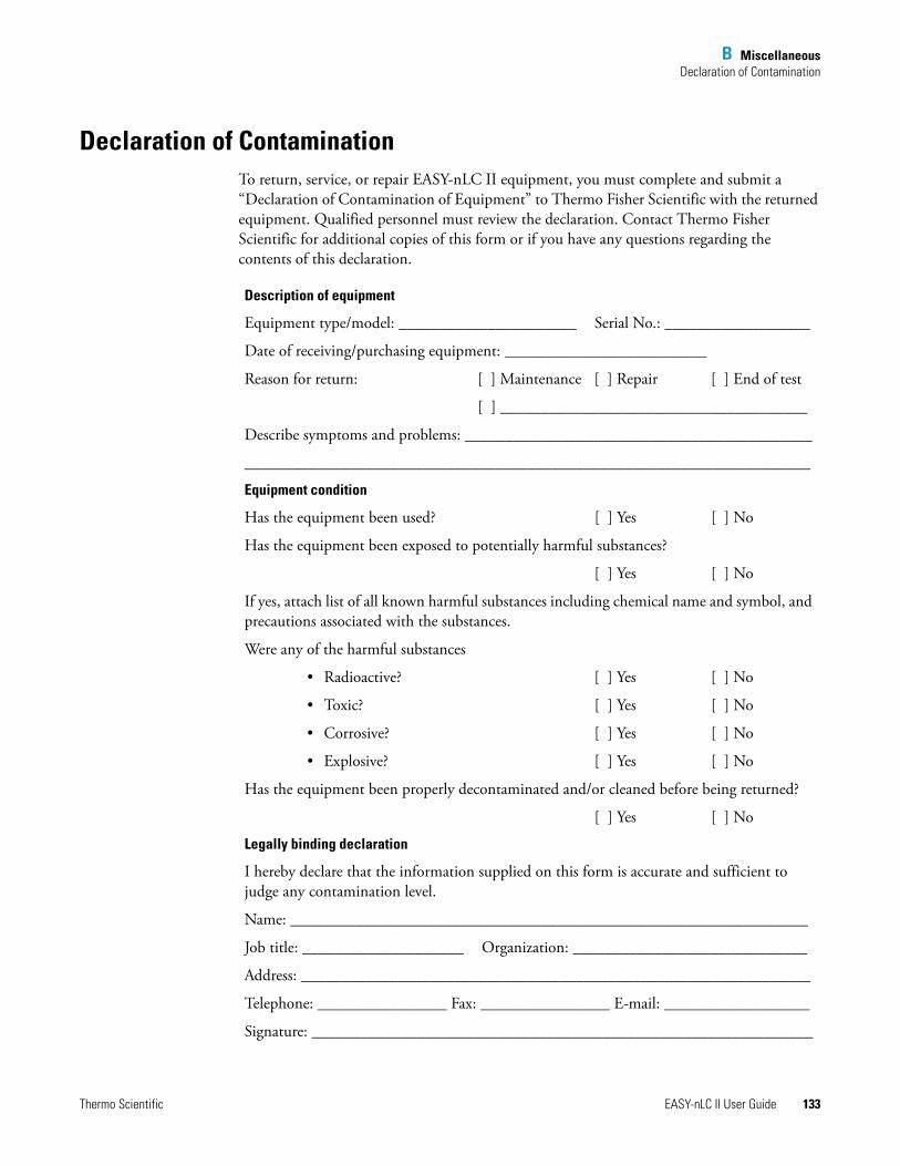
B MiscellaneousDeclaration of Contamination
Thermo Scientific EASY-nLC II User Guide 133
Declaration of ContaminationTo return, service, or repair EASY-nLC II equipment, you must complete and submit a “Declaration of Contamination of Equipment” to Thermo Fisher Scientific with the returned equipment. Qualified personnel must review the declaration. Contact Thermo Fisher Scientific for additional copies of this form or if you have any questions regarding the contents of this declaration.
Description of equipment
Equipment type/model: ______________________ Serial No.: __________________
Date of receiving/purchasing equipment: _________________________
Reason for return: [ ] Maintenance [ ] Repair [ ] End of test
[ ] ______________________________________
Describe symptoms and problems: ___________________________________________
______________________________________________________________________
Equipment condition
Has the equipment been used? [ ] Yes [ ] No
Has the equipment been exposed to potentially harmful substances?
[ ] Yes [ ] No
If yes, attach list of all known harmful substances including chemical name and symbol, and precautions associated with the substances.
Were any of the harmful substances
• Radioactive? [ ] Yes [ ] No
• Toxic? [ ] Yes [ ] No
• Corrosive? [ ] Yes [ ] No
• Explosive? [ ] Yes [ ] No
Has the equipment been properly decontaminated and/or cleaned before being returned?
[ ] Yes [ ] No
Legally binding declaration
I hereby declare that the information supplied on this form is accurate and sufficient to judge any contamination level.
Name: ________________________________________________________________
Job title: ____________________ Organization: _____________________________
Address: _______________________________________________________________
Telephone: ________________ Fax: ________________ E-mail: __________________
Signature: ______________________________________________________________
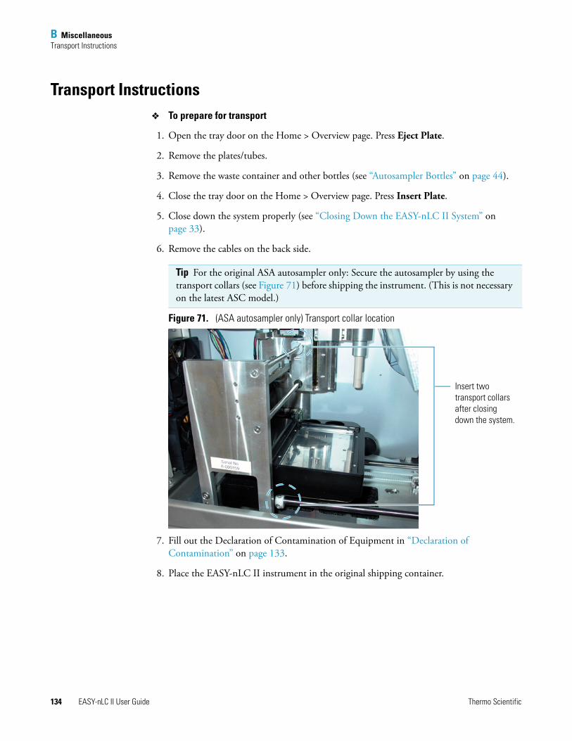
B MiscellaneousTransport Instructions
134 EASY-nLC II User Guide Thermo Scientific
Transport InstructionsTo prepare for transport
1. Open the tray door on the Home > Overview page. Press Eject Plate.
2. Remove the plates/tubes.
3. Remove the waste container and other bottles (see “Autosampler Bottles” on page 44).
4. Close the tray door on the Home > Overview page. Press Insert Plate.
5. Close down the system properly (see “Closing Down the EASY-nLC II System” on page 33).
6. Remove the cables on the back side.
Figure 71. (ASA autosampler only) Transport collar location
7. Fill out the Declaration of Contamination of Equipment in “Declaration of Contamination” on page 133.
8. Place the EASY-nLC II instrument in the original shipping container.
Tip For the original ASA autosampler only: Secure the autosampler by using the transport collars (see Figure 71) before shipping the instrument. (This is not necessary on the latest ASC model.)
Insert two transport collars after closing down the system.

Thermo Scientific EASY-nLC II User Guide 135
I
Aaccounts, adding new 40adapter plate, replacing
ASA autosampler 72ASC autosampler 74
admin, changing password 39advanced flow control system 5AFC See pump flow controlanalytical Col Equilibration script 109analytical column
equilibrating 52installing 50
autosamplerbottles, preparing 44calibration 71checking pickup 104setting to pick up sample 55Torque script 117troubleshooting 90wash 59
BBack Pressure script 116Batch Setup tab 23batch, troubleshooting 88building a gradient 57
Ccalibrating
autosampler 71plates 78wash/waste/vial positions 83
change administrator password 39checking
sample pickup 84solvent levels 103valves 104
column wash 60columns, installing 50
compliance, electromagnetic xivcomponents
system 2troubleshooting 93
Configuration tab 29configuring
devices 40EASY-nLC 32RePlay 126
connectingadd-ons 14mouse and keyboard 14the mass spectrometer 35to the network 36
connection instructions 13consumable parts list 123contact closure, troubleshooting 92control system
advanced 5Intelligent 6
cooler temperature, checking 104creating
a batch with the Microtiter plate 60a method 54new user accounts 40plate formats 75
Ddaily maintenance 103data types graphs 65Declaration of Conformity xivDeclaration of Contamination 133devices, configuring 40
EEASY-nLC II description 2equilibrating the analytical column 52external connections 13
Index

136 EASY-nLC II User Guide Thermo Scientific
Index: F
Fflow control system 5flow line diagram 122flow parts and lines 15flow sensor calibration 104Flow Sensors script 117Flush Air script 107fuse, replacing 124
Ggradient, building 57graphical data types 65
Hhardware overview 7Home tab 22
IIFC See pump flow controlinstalling columns 50instrument
back pressure, checking 104operation 4
Intelligent flow control system 6interface layout 20Isocratic Flow script 110
Kkeyboard connection 14
LLeaks script 113leaks, checking for 104lifting instructions 12low pressure solvent filters 104
Mmaintenance
daily 103quarterly 104scripts 46, 105yearly 104
Maintenance tab 27mass spectrometer connection 35menu structure 21Method Editor tab 25method, creating 54
Microtiter plate 60monitoring the run 63
See also RePlay monitor methodmouse connection 14MS Connection script 111
Nnetwork access, troubleshooting 92network connection 36
Pperformance specifications 119picking up a sample 55plate formats 75plates, calibrating 78power requirements 11pre-column equilibration 58Precolumn Equilibration script 108pre-column preparation 51preparing
autosampler bottles 44pre-column 51solvent bottles and waste containers 43waste container 45well plate 54
product description 2pump flow control
advanced 5description 5Intelligent 6
Purge Solvent script 106purging and flushing pumps 47
Qquarterly maintenance 104
Rreplacing main power fuse 124RePlay
configuring 126connecting to EASY-nLC 125monitor method 131overhead of using 131setup method 128
RePlay (external device), installing and using 125RePlay method 131reset pressure sensor script 118running batch, editing 67

Thermo Scientific EASY-nLC II User Guide 137
Index: S
Ssafety standards (EMC) xivsample
acquisition 63loading, setup 55pick-up check 84Pickup script 112run, troubleshooting 70
saving system files on removable storage 99scripts
Analytical Col Equilibration 109Autosampler Torque 117Back Pressure 116Flow Sensors 117Flush Air 107Isocratic Flow 110Leaks 113Maintenance 105MS Connection 111Precolumn Equilibration 108Purge Solvent 106Reset Pressure Sensor 118Sample Pickup 112Valve Check 114Valve Tune 117
setupmass spectrometer connection 35method with RePlay 128pre-column equilibration 58
solvent bottles, preparing 43solvent levels, checking 103specifications
performance 119technical 120
starting EASY-nLC 19stopping sample acquisition 66system configuration 3system files, saving to removable storage 99system overview, monitoring 64system startup, troubleshooting 93
Ttechnical specifications 120temperature and humidity 12touch screen
interaction principles 21using 18
transport instructions 134troubleshooting
autosampler 90contact closure 92
network access 92running a batch 88sample run 70system components 93system startup 93
turning off EASY-nLC 33
Uuser interface layout 20user permissions 38
VValve Check script 114Valve Tune script 117verifying mass spectrometer connection 63
Wwarranty 123wash column 60waste container, preparing 43, 45well plate, preparing 54
